i UNIVERSITI TEKNIKAL MALAYSIA MELAKA DESIGN DEVELOPMENT OF LOAD CARRIER TYPE AGV This report submitted in accordance with requirement of the Universiti Teknikal Malaysia Melaka (UTeM) for the Bachelor Degree of Manufacturing Engineering (Robotics & Automation) (Hons.) by YAP WAN LOONG B050910283 880712055391 FACULTY OF MANUFACTURING ENGINEERING 2013
Transcript
i
UNIVERSITI TEKNIKAL MALAYSIA MELAKA
DESIGN DEVELOPMENT OF LOAD CARRIER TYPE AGV
This report submitted in accordance with requirement of the Universiti Teknikal
Malaysia Melaka (UTeM) for the Bachelor Degree of Manufacturing Engineering
(Robotics & Automation) (Hons.)
by
YAP WAN LOONG
B050910283
880712055391
FACULTY OF MANUFACTURING ENGINEERING
2013
ii
ABSTRAK
Sistem pengendalian bahan telah diperkenalkan dengan luasnya kepada industri
pembuatan kerana keperluan fleksibiliti dan kualiti. Kenderaan berpandu automatik
akan memainkan peranan penting untuk mencapai keperluan ini kerana ketepatan
yang tinggi dan fungsi kebolehulangannya. Ia boleh menggantikan buruh manusia
bekerja untuk tempoh masa yang lama tanpa mengetahui keletihan. Projek ini akan
mencadangkan tentang bagaimana untuk memperbaiki reka bentuk pada mekanikal
untuk kenderaan berpandu automatik dan menilainya. Jadual kualiti pengaturan
fungsi telah digunakan untuk membuat keputusan kepada pemilihan reka bentuk.
Dengan keperluan dari pelanggan dan ujikaji kejuruteraan, reka bentuk yang sesuai
dan jenis kenderaan akan dipilih. Hasil dari jadual tersebut telah menunjukkan
bahawa kenderaan pembawa beban adalah pilihan yang sesuai untuk diteruskan
kekajian. Kemudian, projek ini akan memberi tumpuan pada kenderaan pembawa
beban sebagai jenis kenderaan baru yang sesuai untuk reka bentuk kenderaan
berpandu automatik kerana kelebihannya. Model trolley akan dibina dengan
menggunakan 3D reka bentuk perisian. Akhirnya, ia akan disimulasi dengan satu
simulasi yang bernama daya statik untuk menguji keadaan kekuatan and cara ubah
bentuk.
iii
ABSTRACT
Material handling system has been widely introduced to manufacturing industries
due to the requirement of flexibility and quality. An automated guided vehicle will
play an important role to achieve the requirement for the material handling system
because of the high accuracy and repeatability function. It can replace the human
labour working for a long time period without getting fatigue. This project is about
how to improve the mechanical design for AGV and evaluate it. Quality function
deployment has been used to decide the design selection. With the customer
requirement and engineering voice in QFD, the suitable design and type of AGV
will be selected. The result from QFD has showed that the unit load carriers are the
suitable choice to be continued develops. Then, this project is focused on using unit
load AGV carriers for the new type of AGV design due to the advantage of this type
of AGV. The model preparation of AGT is designed by using SolidWorks 3D
drawing software and performed simple static force simulation on it.
iv
ACKNOWLEDGEMENT
I would like to acknowledge the following people for their support and
assistance with this project. I would like to extend my thankfulness to the most
precious persons in my life, my father and mother for all their moral support,
financial support and also to my friends for never ending reminding me to always be
honest and trustworthy. As my supervisor from University Technical Melaka
Malaysia (UTeM), Dr. Fairul Azni B. Jafar and CO. Supervisor, En. Mahasan B.
Mat Ali. I thank you for all the reprimand and guidance as it is very helpful for me
in completing my report project.
v
TABLE OF CONTENT
Abstrak i
Abstract ii
Acknowledgement iii
Table of Content iv
List of Tables vii
List of Figures viii
List Abbreviations xi
CHAPTER 1: INTRODUCTION
1.1 Background 1
1.2 Problem Statement 2
1.3 Objectives 2
1.4 Scope of the Project 3
1.5 Project Limitation 3
1.6 Report Structure 3
CHAPTER 2: LITERATURE REVIEW
2.1 Material Handling 5
2.2 Automated Guided Vehicle 6
2.2.1 AGV System 7
2.2.2 AGV Guidance Technique 7
2.2.3 AGV Addressing Mechanism 8
2.2.4 AGV Vehicles Types 8
2.2.4.1 Towing Vehicles 9
2.2.4.2 Pallet Trucks 11
2.2.4.3 Unit-load Carriers 14
2.3 Comparison between Types of AGV 17
2.4 AGV Drive and Steering Option 18
2.5 Existing Unit Load Carrier AGV in Industry 20
2.5.1 AGV-T-2500 Wire Guided Vehicle 21
vi
2.5.2 PLR-T-SB Rider Transport 22
2.6 Chapter Summary 23
CHAPTER 3: METHODOLOGY
3.1 Proposed Idea
3.1.1 Current Existing AGV 24
3.1.2 Company Trolley 26
3.1.3 The Reason for New Design and Improvement 28
3.2 The Theory of Design 29
3.3. Overall Method 30
3.3.1 Method Description 31
3.3.2 Product Planning by Quality Function Deployment 32
3.3.3 Design Process 33
3.3.4 Design Selection 35
3.3.5 Evaluation 35
3.4 Chapter Summary 36
CHAPTER 4: DISCUSSION AND RESULTS
4.1 Design Result
4.1.1 Concept Design Drawing 37
4.1.2 Actual Trolley Design 38
4.1.2.1 Design of 3 Wheels 38
4.1.2.2 Design of 4 Wheels 44
4.2 Weight Calculation and Torque Estimation
4.2.1 Weight and Torque Estimation 50
4.2.2 Rear Wheel Gear Suggestion 52
4.2.3 Front Wheel Gear Suggestion 53
4.3 SolidWorks Static Force Simulation
4.3.1 Step of Static Force Simulation 54
4.3.2 Fixed Geometry 56
4.3.3 Structure of Excess Deformation 58
4.3.4 Result of Stress 59
4.3.5 Result of Strain 61
vii
4.3.6 Result of Displacement 63
4.3.7 Top AGV Box Cover Simulation 65
4.4 Chapter Summary 67
CHAPTER 5: CONCLUSION
5.1 Conclusion 68
5.2 Future Study 69
REFERENCES 70
APPENDICES
A Gantt chart PSM 1
B Gantt chart PSM 2
C Questionnaire Paper Answer
viii
LIST OF TABLES 2.1 Comparison between types of AGV 17
2.2 AGV drive and steering option 18
3.1 Characteristics of good design versus bad design 29
3.2 Relationship matrix between customer requirement and
engineering characteristic 32
4.1 Result of load VS torque 51
ix
LIST OF FIGURES
2.1 (a) Example of towing vehicle 9
2.1 (b) Example of towing vehicle 10
2.2 (a) Example of pallet trucks 11
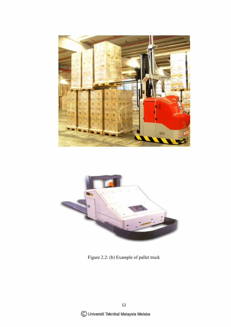
2.2 (b) Example of pallet trucks 12
2.2 (c) Example of pallet trucks 13
2.3 (a) Example of unit-load carriers 14
2.3 (b) Example of Unit-load carriers 15
2.4 AGV-T-2500 wire guided vehicle 21
2.5 PLR-T-SB rider transport 22
3.1 Current existing design picture 1 24
3.2 Current existing design picture 2 25
3.3 Front view of the trolley 26
3.4 3D view of the trolley 26
3.5 Trolley A 27
3.6 Trolley B 27
3.7 Prototype idea design 1 32
3.8 Prototype idea design 2 32
4.1 Concept design of 3 wheel trolley 37
4.2 Concept design of 4 wheel trolley 38
4.3 3D view of AGV trolley from top 39
4.4 3D view of AGV trolley from bottom 39
4.5 Front view of 3 wheel AGV trolley 40
4.6 Bottom view of 3 wheel AGV trolley 40
4.7 Side view of 3 wheel AGV trolley 41
4.8 3D view of AGV box 41
4.9 3D view of circuit board placement 42
4.10 AGV box content 42
4.11 Front view of AGV box 43
x
4.12 Side view of AGV box 43
4.13 3D view of 3 wheel AGV trolley frame 44
4.14 3D view of 4 wheel AGV trolley from top 45
4.15 3D view of 4 wheel AGV trolley from bottom 45
4.16 Front view of 4 wheels AGV 46
4.17 Bottom view of 4 wheels AGV 46
4.18 Side view of 4 wheels AGV 47
4.19 3D view of AGV box 47
4.20 3D view of AGV box content 48
4.21 Front view of AGV box 48
4.22 Side view of AGV box 49
4.23 3D view of 4 wheel AGV trolley frame 49
4.24 Graph of load VS torque 51
4.25 Worm gear 52
4.26 Bevel gear 53
4.27 Stainless steel property menu 55
4.28 Model meshing 55
4.29 Original frame fixed geometry 56
4.30 3 wheel AGV frame fixed geometry 56
4.31 4 wheel AGV frame fixed geometry 57
4.32 Prediction of excess deformation for original AGV trolley frame 58
4.33 Prediction of excess deformation for 3 wheel AGV trolley frame 58
4.34 Prediction of excess deformation for 4 wheel AGV trolley frame 59
4.35 Stress result of original AGV trolley frame 59
4.36 Stress result of 3 wheel AGV trolley frame 60
4.37 Stress result of 4 wheel AGV trolley frame 60
4.38 Strain result of original AGV trolley frame 61
4.39 Strain result of 3 wheel AGV trolley frame 61
4.40 Strain result of 4 wheel AGV trolley frame 62
4.41 Displacement result of original AGV trolley frame 63
4.42 Displacement result of 3 wheel AGV trolley frame 63
4.43 Displacement result of 4 wheel AGV trolley frame 64
4.44 Stress result of AGV top box cover 65
xi
4.45 Displacement result of AGV top box cover 65
4.46 Strain result of AGV top box cover 66
4.47 Prediction result of excess deformation 66
xii
LIST OF ABBREVIATIONS
CAD - Computer Aided Design
UTeM - University Technical Malaysia Melaka
AGV - Automated Guided Vehicle
LGV - Laser guided vehicles
SGV - Self-guided vehicles
P&D - Pick-up and deposit
SCR - Silicon Controlled Rectifier
QFD - Quality Function Deployment
U.S.A - United State of American
JIT - Just In Time
AS/RS - Automated Storage/ Retrieval System
FM - Facility Management
DC - Direct Current
AGT - Automated Guided Trolley
FEA - Finite Element Analysis
1
CHAPTER 1INTRODUCTION
1.1 Background
Nowadays material handling system has become important due to the requirement of
quality and quantity. Because of that, the creation of Automated Guided Vehicle
(AGV) has been introduced to the industries for the purpose of increase the product
handling speed and decrease the human labor cost. Based on the definition from
Wikipedia, it defines the AGV as a mobile robot that follows markers or wires in the
floor, or uses vision or lasers.
The first AGV was created by Berrett Electronics in 1953 (Wikipedia
foundation, 2012). This AGV is able to tow objects behind them in trailers to which
they can autonomously attach. The trailers can be used to transfer the material and
finished product. This is also the idea from the company to the UTeM. The first idea
for the trolley-towing AGV is under towing function. It was uses to tow the trolley
from one point to another point without any human intersection.
In a traditional company system, human labor is very important for the
productivity. But, the AGV can safely achieve this requirement with an intelligent
computer. AGV is easy to be control and able to communicate with other
autonomous vehicles to provide a seamless operation. In case to design an AGV, the
engineer designer requires considering trade-offs between product attributes in the
areas of cost, weight, manufacturability, quality, and performance. Difficult
challenge of determining how to arrive at the best overall design need to be faced,
making the right compromises, and not sacrificing in critical attributes like safety.
2
1.2 Problem Statement
The reason to create an Automated Guided Vehicle is mainly to solve the logistic
problem that often occurred in the workplaces and reduce the risks of personal injury.
It is widely uses in factories, offices, houses, hospitals and some other place that
cannot be noticed.
The AGV can perform many tasks with a higher accuracy and repeatability.
There are some works such as to tow a trolley from one place to another place by
repeatedly, etc. AGV is more efficient when compared to the human labor that will
simply get tired after working for a whole day. By using a suitable power and drive
system, it can carry and lifting a trolley far more than human workers can be. Robots
will not get tired and their movement is easy to be control at all times. Their
movement will be set up by the programming device to move around and do the job
like collecting and feeding materials.
Besides that, there is a lot of worker need to spend their energy and time to
tow the trolley from loading bay to the conveyor for transferring the seat frame. By
using AGV, it can avoid the worker from getting fatigue and the factories system
would be more systematic. AGV also able to repeatedly doing the same job without
any mistake that may be happen on human workers.
Based on the expectation, the environment of the factories need to be analyze
first before do the designing of a suitable AGV towing robot to prevent any unknown
error. This is the main fact to design and improve the robot.
1.3 Objectives
The objectives of this project:
To design the model preparation of the AGT prototype using computer
software
To perform analysis based on the design automated guided trolley
3
1.4 Scope of the Project
The first design model is a four-wheeled mobile robot that has the ability to follow
line on floor. There are four-wheels including two driving wheels controlled by the
motor and two free wheel in front which are for steering purpose. With four wheels,
the wheels are always in contact with the surface because there is a higher driving
force to tow the trolley. In this case, the final decision is to modify the simple trolley
prototype to operate in AGV function. The model of this idea is same type as the unit
load AGV carries. By using SolidWorks CAD software, it can design and show the
AGV model is solid state drawing. The work in this project is focusing more on the
development on the mechanical design of the AGV.
1.5 Project Limitation
The main problem to be considered is how to modify the trolley becomes a
unit load carriers to add in the extra equipment without increase the load. It is also
important to know the actual working environment either the factory have enough
area to let the robot operated or not.
1.6 Report Structure
Chapter one is discussing about the introduction of the report that first start with
background of the AGV, problem statement, objectives, scope of the project, project
limitation.
Chapter two is start with literature review. This chapter have describe the material