University of Konstanz Department of Computer and Information Science Bachelor Thesis for the degree Bachelor of Science (B.Sc.) in Information Engineering Evaluation of the Matlab Simulink Design Verifier versus the model checker SPIN by Florian Leitner (Matr.-Nr. 01 / 612538) 1 st Referee: Prof. Dr. Stefan Leue 2 nd Referee: Prof. Dr. Ulrik Brandes Konstanz, July 21, 2008
Transcript
University of Konstanz
Department of Computer and Information Science
Bachelor Thesis for the degree
Bachelor of Science (B.Sc.) in Information Engineering
An increasing number of industrial strength software design tools come along with veri-fication tools that offer some property checking capabilities. On the other hand, there isa large number of general purpose model checking tools available. The question whetherusers of the industrial strength design tool preferably use the built-in verification tool ora general purpose model checking tool arises quite naturally. In this bachelor thesis, theSimulink Design Verifier and the SPIN model checking tool are compared. The comparisonis based on the case study of an AUTOSAR compliant memory management module. Thecomparison is both functional in that it analyzes the suitability to verify a set of basic sys-tem properties, and quantitative in comparing the computational efficiency of both tools.In this context, it is also described how Simulink / Stateflow models can be manuallytranslated into the input language of the model checker SPIN.
Kurzfassung
Eine steigende Anzahl von industriell eingesetzten Software Design Werkzeugen, bietetMoglichkeiten “Korrektheitseigenschaften“ zu verifizieren. Andererseits, gibt es eine großeAnzahl an allgemeinen Model Checking Werkzeugen. Naturlich stellt sich nun die Frage, obder Benutzer eines industriellen Software Design Werkzeuges nun das eingebaute Verifizierungs-Werkzeug benutzen sollte, oder ob er eines der allgemeinen Model Checking Werkzeugebevorzugen sollte.
In dieser Bachelorarbeit wird der Simulink Design Verifier mit dem model checkingWerkzeug SPIN verglichen. Dem Vergleich liegt die Fallstudie eines AUTOSAR kom-patiblen Speicherverwaltungs-Modul zu Grunde. Der Vergleich ist sowohl funktional, daanalysiert wird, inwieweit sich die Werkzeuge dazu eignen eine ausgewahlte Menge an“Korrektheitseigenschaften“ zu verifizieren, als auch quantitativ da die Effizienz der bei-den Werkzeuge verglichen wird. Im Zusammenhang wird auch beschrieben, wie Simulink/ Stateflow Modelle manuell in die Eingabesprache des Model Checker SPIN ubersetztwerden konnen.
2
Acknowledgments
Leider laßt sicheine wahrhafte Dankbarkeit
mit Worten nicht ausdrucken.- Johann Wolfgang von Goethe -
Firstly, I want to thank my supervisor Stefan Leue for his outstanding guidance and men-toring, but also for giving me the chance to present my work at FMICS 08.I want to thank Ulrik Brandes for agreeing to be the second referee of this thesis.
I thank the whole software engineering group at the University of Konstanz for providinga great and friendly work climate.
I am indebted to my family for the support and encouragement during the last years.My special gratitude goes to Viktoria for her love and understanding and for her continuousmotivation.
It is increasingly common for industrial strength software design tools for embedded real-time systems to provide verification capabilities. This capabilities aid in checking softwaredesign models for important system properties. Examples include the SDL tool TelelogicTAU1, the Statemate ModelChecker2 and the Simulink Design Verifier3 which is an op-tional component of the Matlab/Simulink tool set. These verification tools are tightlyintegrated with the design tool that they belong to. The design tools are typically domainspecific. The Telelogic TAU tool, for instance, enjoys widespread popularity in telecommu-nications while Matlab/Simulink is a de-facto standard for software design in automotivesystem engineering [1].
On the other hand, there is a large number of model checking tools available that arenot tightly integrated with some software design tool, but instead can be used as stand-alone tools and possess a tool-specific input language. Examples of such tools includeSMV [2], NuSMV [3] and SPIN [4]. There is a tendency in the literature to view sym-bolic model checking tools such as SMV and NuSMV to be more suitably applicable inthe hardware domain, since they seem to deal particularly well with regularly structuredsystems. Symbolic model checking also seems to more adequately deal with data orienteddesign models. Explicit state model checking on the other hand, as implemented in SPIN,is generally viewed to cope more easily with irregularly structured concurrent softwaresystems [4].
Designers of safety-critical software applications are faced with the challenge to decidewhether they should rely on the use of the built-in verification engines, or whether theyshould invest effort and resources into either a manual translation of their design mod-els into the input language of a general purpose model checker, or even into building atranslation tool that automatically translates their design into a general purpose modelchecking tool. It is the objective of this bachelor thesis to discuss the basis for this decision
making in the setting of a software system from the automotive domain. For the purposeof this comparison, we consider the Simulink Design Verifier, since it is integrated into adomain-specific design tool, and the model checker SPIN, since it seems an obvious choicefor the analysis of the type of concurrent software that we analyze.
For the assessment of the alternatives we use the design of a Non Volatile RandomAccess Memory Manager (NVRAM) component from the AUTOSAR4 automotive opensystem architecture. AUTOSAR is being defined by many representatives of the automo-tive industry in order to facilitate the collaboration of automotive component suppliersand car manufacturers by specifying component interaction interfaces. The choice of theNVRAM component is justified by the fact that it is relatively generic in the architecture,since every electronic control unit (ECU) will need to provide its own NVRAM component.
The study that we present compares the two verification approaches both qualitativelyand quantitatively. We propose a set of central requirements on the NVRAM componentthat we wish to be verified for our design. We then discuss whether and how they canbe verified using either of the approaches. For those requirements that can be verifiedusing both approaches we compare the performance of both. We also comment on theeffort necessary to convert the Stateflow model to Promela, the input language of theSPIN tool. For the time being this translation is manual. We decided not to translateStateflow directly into Promela, but to use the visual modeling tool VIP [5] as a targetfor the manual translation. VIP is a visual modeling interface that allows for concurrentsystem modeling using hierarchical, communicating state machines. VIP compiles efficientPromela code that encodes states using a state-label and goto mechanism. Notice that ouranalysis does not hinge upon the use of VIP, even though we perceive it as supporting themanual translation well.
1.2 Related Work
The verification engine underlying Simulink Design Verifier is based on SAT solving tech-nology [6]. There is a substantial body of literature available that discusses formal se-mantics and analysis approaches to Matlab/Simulink and the Stateflow language. Anoperational semantics of Stateflow based on Plotkin rules [7] is defined in [1]. The authorsobserve that in spite of the relative complexity of the Stateflow language, the portionthat is generally recommended to be used in practics has a surprisingly easy semantics.In [8] the formal semantics of a fragment of Stateflow is described based on a modularrepresentation called communicating pushdown automata. Various papers describe trans-lations of the Stateflow language into various model checking tools. A translation into thesymbolic model checker SMV is presented in [9] while [10] discusses a translation into theNuSMV symbolic model checker, a successor to SMV. The paper [11] suggests an analysisof Simulink models using the SCADE design verifier in the particular setting of systemsafety analysis. Another translation from Stateflow to Lustre is described in [12]. Bothshare the interpretation of Simulink and Stateflow as a synchronous language, as man-dated by the use of Lustre as the target language for the translations. Invariance checking
4http://www.autosar.org
CHAPTER 1. INTRODUCTION 8
of Simulink/Stateflow automotive system designs using an symbolic model checker is pro-posed in [13]. A first attempt to validate Stateflow designs using SPIN is presented in [14].However, the translation tool used is not publicly available and it is therefore difficult tocompare with this approach. In conclusion, we are not aware of any study that relatesthe Simulink Design Verifier tool to the SPIN model checker, which is the focus of thisbachelor thesis.
1.3 Structure of the Thesis
In Chapter 2 an overview about Simulink, Stateflow and the Simulink Design Verifier onthe one hand and VIP, SPIN and Promela on the other hand is given. The Translation fromSimulink / Stateflow to VIP / Promela is described in Chapter 3. An introduction to theNVRAM case study is given in Chapter 4. The evaluation of the verification capabilitiesof Simulink Design Verifier and SPIN will be presented in Chapter 5. We conclude inChapter 6.
Chapter 2
Simulink and SPIN
2.1 Matlab / Simulink / Stateflow
2.1.1 Overview
Matlab1 is developed and distributed by The MathWorks2 and is a Software for numericalcomputations. The name Matlab is derived from MATrix LABoratory. Simulink3 extendsMatlab with the capabilities to design and simulate dynamic and embedded systems in agraphical environment. Simulink models are block diagrams, that consist of blocks fromthe Simulink block library, which are connected with Simulink signals. Stateflow4 extendsSimulink with the possibility to develop state machines. All together Matlab, Simulinkand Stateflow build an industrial strength software design tool for embedded systems, thatis widely used in the avionics and automotive field.
2.1.2 Simulink
Simulink is an extension of Matlab, that allows for design and simulate embedded systems,which are modeled as block diagrams. In this section an overview of Simulink and itssemantic is given based on [15]. Simulink is capable of model both continuous systems anddiscrete systems. One Simulink block can consist of one and more other Simulink blocksand therefore build a hierarchical block diagram. In Simulink there are two kind of blocks,nonvirtual blocks and virtual blocks. Nonvirtual blocks are used to represent elementarysystems. Whereas virtual blocks have no effect in the definition of the systems of equationsdescribed by the block diagram and are just used to make the modeling more convenient.An example of such a virtual block is the bus creator block, which allows for grouping twoor more signals, thus the user needs only to draw one instead of two (or more) signal linesfrom one block to another.
Simulink block diagrams define time-based relationships between signals and state vari-ables. By evaluating those relationships over time, a solution for the block diagram can
be obtained. The start and stop time for this evaluation is specified by the user. Signalvalues are defined for all points in time between the simulation of the block diagram hasbeen started and the time when the simulation is finished. The relationships betweensignals and state variables are defined by a set of equations represented by blocks. Eachblock consists of a set of equations, which are defining the relationship between the inputsignals, the output signals and the state variables. The state variables are representingthe computational results of the previous time step.
2.1.3 Stateflow
Stateflow supports the creation of Stateflow diagrams, which are a variant of the finitestate machine notation established by Harel [16]. In addition, it is also possible to drawstateless flow chart diagrams. A Stateflow chart can be integrated into Simulink and Datacan be passed from Simulink to Stateflow charts and vice versa. To organize the Stateflowcharts of complex systems, Stateflow allows for hierarchical and parallel Stateflow charts.But even though Stateflow allows to define parallel states, the execution order of this statesis always statically known and sequential. Hierarchy means, that you have the possibilityto define parent and child states. In the following a brief overview of the Stateflow Ele-ments is given based on [17] Each state can be labeled with the following labels:
name
entry: entry actions
during: during actions
exit: exit actions
Where name represents the name of a state, entry actions are all actions that are exe-cuted when the state is entered, during actions are all actions that are executed whilein a state and exit actions are executed when a state is left. To describe these actions,Stateflow uses an own C like language that is defined in [17]. The transitions leading fromone state to another can be labeled in the following way:
If the event occurs, the transition will be taken, if the condition is true. Specifying anevent is optional if no event is specified, the transition can be taken if the condition istrue. In case no condition is specified, this will have the same effect then specifying acondition that is always true. The condition action is executed as soon as the conditionis evaluated to true. If no condition is specified the condition action will always beexecuted. After the transition destination has been determined to be valid the transitionaction will be executed.
The Semantics of Stateflow are described informally in the user guide [17] and a largeportion is defined through its behavior while simulated. In [1] Hamon and Rushby definean operational semantics for Stateflow. Tiwari describes in [8] the formal semantics of afragment of Stateflow based on a modular representation called communicating pushdownautomata.
CHAPTER 2. SIMULINK AND SPIN 11
2.1.4 Simulink Design Verifier
Simulink Design Verifier (SDV) is an extension of the Mathworks Matlab / Simulink toolset. It performs exhaustive formal analysis of Simulink models to confirm the correctnessof Simulink models with respect to given properties. The user can specify these propertiesdirectly in Simulink and Stateflow as assertions. The assertions are specified in the formof prove objectives. To prove these objectives, Simulink Design Verifier searches for allpossible values for a Simulink or Stateflow function in order to find a simulation thatsatisfies an objective. Simulink Design Verifier does not expect a model to be closed. Itwill compute all possible input signals automatically. As written in [18] Simulink DesignVerifier uses the Prover Plug-In [6] in order to prove properties. The Prover Plug-In isdeveloped and maintained by Prover Technology 5. The key idea of the Prover Plug-In isto model problems as propositional logic formulas and to apply proof methods to decidewhether the formulas are tautologies, that is the the formula evaluates to true for allassignments, or not. This problem is solved by the Prover Plug-In using a reductio adabsurdum argument, where a combination of different analyses is used to check whetherthe negation of the formula is unsatisfiable.
As was also observed in [1], Simulink does not support an interpretation of concurrencyin terms of a nondeterministic interleaving of concurrent events. Even if Stateflow chartscould be executed concurrently, Simulink will interpret their execution in an predefined,deterministic order based on the visual layout of the chart. The Simulink Design Verifierdoes not provide any means to check a model for any type of concurrency related properties,such as race conditions. Likewise, deadlocks could only be detected if the one deterministicexecution that Simulink permits happens to end in a deadlocked state.
5http://www.prover.com/
CHAPTER 2. SIMULINK AND SPIN 12
2.2 SPIN / Promela / VIP
2.2.1 SPIN and Promela
SPIN is an explicit state model checking tool. The Promela modeling language, whichis interpreted by SPIN, allows for describing concurrent system models. The concurrentprocesses in Promela synchronize via asynchronous or synchronous message passing, andvia shared variables. SPIN implements a simple Depth-First Search algorithm for safetyproperties, and a nested Depth-First Search for properties specified in Linear TemporalLogic. In order to deal with large state spaces SPIN offers bit state hashing as wellas automated partial order reduction. SPIN has been applied in the analysis of manyconcurrent software systems. A very comprehensive overview of SPIN is given in [4].
2.2.2 VIP
VIP was designed as a visual input language for the SPIN model checker. VIP follows theideas of the modeling language UML-RT [19] for the visual specification of system designs.Concurrent software components are modeled as capsules. The behavior of the system isspecified using hierarchical state machines. Out of the diagrams VIP compiles Promelacode, the input language of the SPIN model checker. In the compiled Promela modelstates are represented using Promela labels, and state transitions using goto statements.Transitions and states can be labeled with Promela code. Currently, VIP does not supportmodel checking result interpretation at the level of the VIP model. However, it is easy totrace counterexamples in the generated Promela code back to the original VIP model. Fordetails on VIP we refer the reader to [5].
Chapter 3
Translating the Model
3.1 Translation Workflow
In order to compare the capabilities of the Simulink Design Verifier and SPIN, the modelhas to be translated from Simulink / Stateflow into VIP / Promela. In [14] a Tool thatperforms such a translation is described, but hence this tool is not public available we hadto come up with our own mapping. Our approach to map Stateflow elements to Promeladiffers in the way that in [14] Promela variables where used to model states whereas we areusing Promela labels and goto statements to model states. The reason for this decision isthat according to measurements documented in [20] the state space size for using Promelavariables to store states is about twice the size as if Promela labels and goto statementsare used. While the state vector size remains the same for both variants.
The translation is based on the semantics of Stateflow described in [1] and [8]. Sincethe Simulink / Stateflow model will be translated in C code in order to run on a embeddedsystem, we allowed deviations of translation from the Simulink / Stateflow semantics incase of being more suitable to model the actual system.
Figure 3.1: Translation Workflow.
Figure 3.1 shows the translation workflow, first the Simulink / Stateflow model ismanually translated into a VIP model. After that the automatic translation from VIP toPromela is used to build a Promela model. VIP was selected for this first step of translation,because it provides a graphical user interface and thus a similar way of modeling systemslike with Simulink / Stateflow. Hence, human errors that are potentially introduced via adirect translation into Promela code are avoided. We describe here the mapping betweenSimulink / Stateflow elements and VIP / Promela elements.
13
CHAPTER 3. TRANSLATING THE MODEL 14
3.2 Translating Simulink Elements
3.2.1 Simulink Subsystems
Simulink Subsystems can be translated to VIP capsules or Promela proctypes.
3.2.2 Simulink Signals
Simulink Signals can be translated into global variables. While in Simulink an outputport of one subsystem is connected via a signal to an input port of an other subsystem, inVIP / Promela we propose the usage of one global variable that can be accessed by bothcapsules / proctypes.
3.2.3 Inports / Outports
Due to the fact, that signals are translated into global variables and in- and out-portsrepresent writing or reading of signal values, in- and out-ports can be translated to variableassignments and the reading of variable values.
3.2.4 Logic and Math Operators
Logic and math operators can be modeled by performing the same logical or mathematicaloperation with Promela.
3.2.5 Data Stores
Data Stores can be represented in VIP / Promela using variables. The read / write datastore element can be represented with reading the value of a variable and respectivelyassigning a new value to a variable.
3.2.6 Mux / Demux
Mux block combines signals into an vector, while a demux block takes an vector as inputand has one output signal for each element of the vector. This behavior can be modeledin VIP / Promela using an array of variables.
3.2.7 Sources
Simulink provides a group of block elements called sources, which are creating output signalsequences with defined algorithms (e.g. Random Numbers, Sine Wave, Pulse Generatoretc.). These blocks can be implemented in VIP / Promela, by implementing the underlyingalgorithm.
3.2.8 Sinks
Sinks (e.g Scopes, Displays etc.) are used in Simulink for simulation purposes and are notneeded to be translated.
CHAPTER 3. TRANSLATING THE MODEL 15
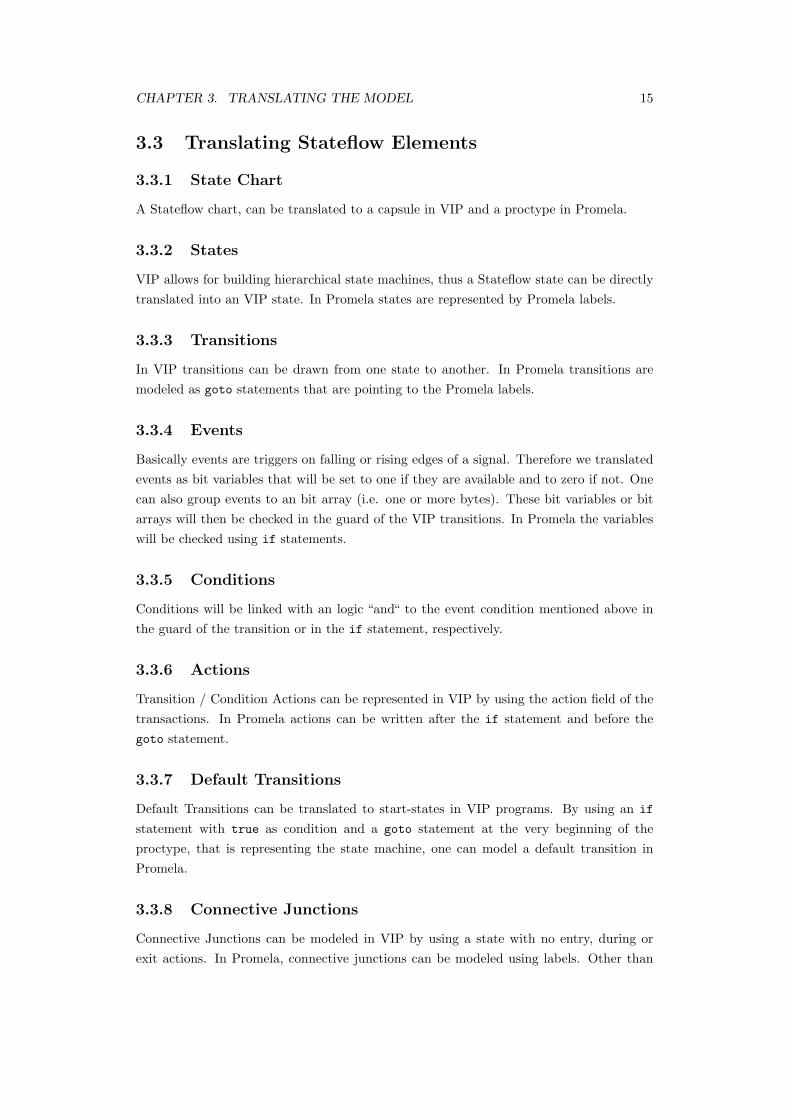
3.3 Translating Stateflow Elements
3.3.1 State Chart
A Stateflow chart, can be translated to a capsule in VIP and a proctype in Promela.
3.3.2 States
VIP allows for building hierarchical state machines, thus a Stateflow state can be directlytranslated into an VIP state. In Promela states are represented by Promela labels.
3.3.3 Transitions
In VIP transitions can be drawn from one state to another. In Promela transitions aremodeled as goto statements that are pointing to the Promela labels.
3.3.4 Events
Basically events are triggers on falling or rising edges of a signal. Therefore we translatedevents as bit variables that will be set to one if they are available and to zero if not. Onecan also group events to an bit array (i.e. one or more bytes). These bit variables or bitarrays will then be checked in the guard of the VIP transitions. In Promela the variableswill be checked using if statements.
3.3.5 Conditions
Conditions will be linked with an logic “and“ to the event condition mentioned above inthe guard of the transition or in the if statement, respectively.
3.3.6 Actions
Transition / Condition Actions can be represented in VIP by using the action field of thetransactions. In Promela actions can be written after the if statement and before thegoto statement.
3.3.7 Default Transitions
Default Transitions can be translated to start-states in VIP programs. By using an if
statement with true as condition and a goto statement at the very beginning of theproctype, that is representing the state machine, one can model a default transition inPromela.
3.3.8 Connective Junctions
Connective Junctions can be modeled in VIP by using a state with no entry, during orexit actions. In Promela, connective junctions can be modeled using labels. Other than
CHAPTER 3. TRANSLATING THE MODEL 16
that, some additional steps are necessary to preserve the semantics of Stateflow, which aredescribed in 3.4.3.
3.3.9 Input / Output Variables
Input and Output variables of Stateflow chart, are representing the values of Simulinksignals and as earlier mentioned, Simulink signals can be translated to global variablesboth in VIP and in Promela.
3.3.10 Local Variables
Local variables can be translated to variables that are declared in the VIP capsule, respec-tively in the Promela proctype.
CHAPTER 3. TRANSLATING THE MODEL 17
3.4 Preservation of the Semantics of Simulink and State-
flow
3.4.1 Concurrency
VIP creates a concurrent proctype for each capsule which results in a concurrent systemmodel. However, as already mentioned in 2.1.4 Simulink and Stateflow models are exe-cuted in a sequential order. To model non-concurrent execution in VIP / Promela, a globalvariable lock is introduced, that controls the execution of the state machines and producesthe same sequential execution order like in the Simulink / Stateflow order. The sameconcept applies to parallel Stateflow states, where the execution order is also sequential.Nevertheless, in some cases it may be desired to have the concurrent version available forverification, because this model may be more close to the real implementation.
3.4.2 Nondeterminism
Stateflow does not allow for having nondeterministic state machines. If two outgoing tran-sitions of a state are valid a the same time (like in Figure 3.2, one of them will be selectedin an deterministic way. This is done using the Stateflow 12 o’clock rule [12]: starting at12 o’clock position of a state and proceeding clockwise around the state, conditions areevaluated and the first transition that is enabled will be taken. If for example in Figure3.2 p and q are true at the same time, always the transition labeled with [p = true] willbe taken. Since this approaches relies on the graphical positions of the transitions, it may
Figure 3.2: Stateflow graph with two enabled transitions.
lead to undesired behavior and small changes (removing a transition or reordering twotransitions) can have a big impact on the systems behavior. Hence we propose to allowSPIN to nondeterministically choose one of the enabled transitions. The correspondingtranslation for this approach to VIP can be seen in Figure 3.3(a). Figure 3.3(b) showshow the deterministic semantic of the 12 o’clock rule can be modeled with VIP.
We translate connective junctions to states. But to preserve the semantics of Stateflow,some additional steps are needed. Stateflow uses the 12 o’clock rule to search for enabledoutgoing transitions (step 1). If an enabled transition is found, it will be taken (step 2). Ifnow a connective junction is reached, the outgoing transitions of the connective junctionswill be checked according to the 12 o’clock rule (step 3). If one of the transitions is enabledand leads to a state it will be taken and the search is completed (step 4). (Step 2 and3 can occur repeatedly.) But if none of the outgoing transitions of a connective junctionis enabled, Stateflow will backtrack to the previous connective junction, without undoingthe actions made while executing the transitions. An example of this behavior is given inFigure 3.4, the gray arrows show the execution order. At first, the transition two the leftconnective junction is taken, then according to the 12 o’clock rule the transition labeledwith 1 is taken. At the next connective junction, there is no enabled transitions andStateflow is backtracking to the first connective junction without undoing the transitionaction (x = x + 2). Then the transition labeled with 2 is taken. When state C is entered,x is 4 and not as one would expect 2.
Figure 3.4: Backtracking in Stateflow
CHAPTER 3. TRANSLATING THE MODEL 19
Figure 3.5: Backtracking in VIP
Figure 3.5 shows how the backtracking behavior can be achieved in VIP. The statesstarting with cj are representing the connective junctions and the states starting with xare needed to represent the 12 o’clock rule. The transition actions are specified in theaction field of the transition properties.
Chapter 4
The NVRAM Case Study
4.1 AUTOSAR and the NVRAM Manager
The complexity of electronic and software components in cars has reached a very high leveland is still increasing. Consequently, the automotive industry is seeking new techniques toensure the quality and most important the safety of automotive products. The AutomotiveOpen System Architecture (AUTOSAR) is a standardized software architecture whosemain goal is to increase the hardware independence of single software modules and strivestowards high reuse. AUTOSAR also promotes the usage of commercial and well tested off-the-shelf software and will also help to reduce the development costs of automotive systems.A further objective of AUTOSAR is to increase interoperability of automotive controlunit software components in order to facilitate integrating components manufactured bydifferent manufacturers. Figure 4.1 shows the different layers of the AUTOSAR softwarearchitecture.
Figure 4.1: AUTOSAR Software Architecture
20
CHAPTER 4. THE NVRAM CASE STUDY 21
For this case study we selected the AUTOSAR Non Volatile Random Access MemoryManager (NVRAM Manager) component as specified in [21]. The NVRAM Managerprovides the central memory management of AUTOSAR control units. The random accessmemory (RAM), the read only memory (ROM) and the non volatile memory (NVM)are managed by the NVRAM Manager. The application has only access to the RAM.Upon request from the application the NVRAM Manager copies data from ROM to RAM,RAM to NVM or vice versa. The NVRAM Manager provides services to ensure the datastorage and maintenance of non volatile data according to the individual requirements inan automotive environment. An example for such a requirement is to handle concurrentaccess to the memory. The main reason why we choose the NVRAM Manager for thiscase study, was its independence from the application. Each automotive application hasto control memory, that is why the NVRAM Manager will be found in almost everyAUTOSAR control unit regardless whether this is an airbag control unit or an enginecontrol unit.
Figure 4.2: The NVRAM Manager and its environment.
The block diagram (Figure 4.2) shows the interface of the NVRAM Manager with otherlayers and modules. The interface is provided through the API and callback functions.Neither the NVRAM Manager nor the layers above the NVRAM Manager have directaccess to the non volatile memory. All access from application to the memory is routedthrough the AUTOSAR Runtime Environment (RTE) to the NVRAM Manager. TheNVRAM Manager calls an API function of the memory hardware abstraction, where thecall is forwarder either to the COM driver (external memory) or to the memory drivers(internal memory). The job processing is controlled by a cyclic operating system task,which can be concurrent to the API calls of the application.
CHAPTER 4. THE NVRAM CASE STUDY 22
4.2 The NVRAM Simulink Model
The NVRAM Manager consists of two parts, one for the job scheduling and one for thedata handling. For the purpose of this case study, these two parts are both modeled asSimulink Subsystems. The central function of the NVRAM Manger is the job scheduling,the data management part is just needed to store information about the configurationof the several memory blocks. Therefore we decided to focus this case study on the jobscheduling part.
Figure 4.3: The Stateflow charts AddJob and JobManager.
The job scheduler is modeled using two Stateflow diagrams (Figure 4.3). One of thesediagrams is responsible for adding new jobs to the queue (AddJob), and the other onerepresents the scheduler functionality (JobManager). These two Stateflow diagrams arecommunicating via Simulink signals. Simulink signals can be compared to the concept ofusing global variables for message passing. The AddJob Stateflow diagram is responsiblefor translating the incoming signal calls to a job type and to forward the request to theJobManager. There are five request types, namely write, erase, invalidate, restore andread a block. The requests write, erase, invalidate and restore are translated into writejobs and the read request is translated into a read job. The JobManager has two queues,one for write jobs and one for read jobs. This construction models the fact that write jobshave a higher priority than read jobs.
The signal NvM Signals represents the calls from the application layer to NvM Read,NvM Write, NvM Invalidate, NvM Restore and NvM Erase and is used to add new jobsto the queue. The signal doWork starts the job processing and is called by the NVRAMfunction NvM MainFunction. The NvM MainFunction is triggered by a cyclic operatingsystem task.
We are basing the comparison of Simulink Design Verifier and SPIN on the Mat-lab/Simulink design model for the NVRAM manager that we sketched above. Some ofthe coding features in this model are adequate at the design level, but would impede statespace exploration since they lead to very large state spaces. We therefore performed thefollowing manual abstractions in order to obtain a verification model:
� Normally, the queues are modeled as multidimensional arrays and each job containsthe memory address of the source location and the memory address of the target
CHAPTER 4. THE NVRAM CASE STUDY 23
location. For verification purpose it is sufficient if this array is a one dimensionalarray containing just the type of the job.
� Since the size of the queues has no impact on the functionality, we limited the sizeof the arrays to two elements. If the queue is full and a request is pending, wewill accept this job without adding it to the queue. This abstraction is not propertypreserving with respect to deadlocks. In our experimental evaluation, we will includea model variant in which we block on a full queue in order to show that we can detectthe resulting deadlock.
� The job scheduler normally calls the function of the data handling part to perform therequested operations, but since this does not affect the behavior of the job schedulerwe omitted these calls from the model.
Figure 4.4 shows the Stateflow graph of the JobManager. It consists of 5 states. TheJobManager waits in the idle state for a new command. If the AddJob Statechart sets thesignal InternalSignal to two or four either a new write (state WriteQueueAdd) or a newread job (state ReadQueueAdd) will be added. If the doWork signal is set to one by theenvironment it will start to process the write jobs that are in the write queue, once this isfinished it will process all read jobs and then return to the idle state.
Figure 4.4: Stateflow graph of the JobManager.
CHAPTER 4. THE NVRAM CASE STUDY 24
4.3 The VIP / SPIN Model
As we argued above, the Simulink model of the NVRAM manager was manually translatedin a visual specification using the VIP tool. The behavior of the system is specified usinghierarchical state machines. Out of the diagrams Inter-process communication in theNVRAM case is modeled by means of access to global variables, which we use to mimicthe Simulink signal-based synchronization of processes.
Figure 4.5: VIP graph of the NVRAM System Structure.
Figure 4.6: VIP graph of the NVRAM Manager.
The top level system structure of the NVRAM component consists of two capsules, theEnvironment, which contains the environment behavior, and the NVRAMManager itself, asdepicted in Figure 4.5. The NVRAMManager is decomposed into two capsules named AddJob
and JobManager, c.f. Figure 4.6. Inside these capsules we used the same state machinemachine structure that is also used in the Stateflow charts of the Simulink NVRAM model.Figure 4.7 gives the top level state machine behavior of the JobManager that can easilybe compared to the structure of the Stateflow JobManager state machine in Figure 4.4.Actions are attached to states and transitions, the Figure shows the guard attached tothe transition labeled AddWriteJob. State machines in VIP are hierarchical, and Fig-ure 4.8 gives the state decomposition of the WriteQueueAdd state in Figure 4.7. Noticethe similarity to the corresponding state decomposition in the Stateflow model as given inFigure 4.9.
The syntax of the Simulink / Stateflow language is very similar to C and thus also easyto translate to Promela. Since VIP does not support definition of signals between twostate charts, we used the concept of global variables for message passing. But as explainedearlier, this represents a good mapping of the Simulink signal concept. In contrast tothe Simulink Design Verifier, SPIN can only verify closed models. Closed means that theenvironment behavior is also a part of the model. Therefore we added a third capsule En-vironment that is non-deterministically sending either write or read requests or is startingthe job processing. The behavior of the Environment capsule is given in Figure 4.10.
CHAPTER 4. THE NVRAM CASE STUDY 25
Figure 4.7: VIP graph of the JobManager behavior.
Figure 4.8: VIP graph of the WriteQueueAdd substate.
Figure 4.9: Stateflow graph of the WriteQueueAdd substate.
CHAPTER 4. THE NVRAM CASE STUDY 26
Figure 4.10: VIP graph of the Environment behavior.
VIP creates a concurrent proctype for each capsule which results in a concurrent systemmodel. However, the two state machines in th Simulink model are executed in a sequentialorder. The concurrent execution of these capsules corresponds to the reality of the imple-mentation, in which the corresponding tasks will be executed concurrently. Simulink doesnot allow for the modeling of concurrent behavior. To model the non-concurrent execu-tion in VIP/Promela, we introduced a global variable lock that controls the execution ofthe state machines. The value of the lock variable indicates whether it is the turn of theAddJob, the JobManager or the Environment.
4.4 Verification Properties
In our case study we focus on 6 central properties required to hold of the NVRAM manager.These properties are derived from the following requirements on the NVRAM manager.We give these requirements using the numbering used in the corresponding AUTOSARspecification [21]:
� BSW013 - Handling of concurrent accesses to NVRAM: The NVRAM manager shallprovide a mechanism to handle multiple, concurrent read / write orders, e.g. queuing.
� BSW08541 - Guaranteed processing of accepted write request: The NVRAM man-ager shall guarantee that an accepted write request will be processed.
� BSW08542- Job order prioritization: The NVRAM manager shall provide a prior-itization for job processing order. The highest priority job shall be processed first;jobs with the same priority level shall be executed in FIFO order.
[21] does not specify how many different priorities there are. We assume that the NVRAMmanager will distinguish between write and read requests. As we will show in 5.1.4 themodel can be easily extended to support more than two different priorities.To capture the above mentioned requirements, we are using the following properties:
CHAPTER 4. THE NVRAM CASE STUDY 27
� P1: All write jobs will be processed, before any read request is processed.This property represents BSW08541 and assures, that the job order prioritization ismet.
� P2: If a request is pending, it will eventually be added to the queue.The requirement BSW08541 is represented by this property. This property assures,that pending request will be added to the queue, that is, no job will be ignored.
� P3: If a request was accepted, it has been added to the queue.This property assures proper behavior of the queues and hence represents require-ment BSW013.
� P4: One single request will only be added once to the queue.Like P3 this property assures proper behavior of the queues and therefore representsrequirement BSW013.
� P5: If a request was added to the queue, it eventually will be processed.This property represents both requirement BSW013 and requirement BSW08541.Because it assures that all requests that have been added to the queue will be pro-cessed at some point in the future (BSW08541) and it assures proper behavior of thequeues (BSW013).
� P6: If a request was processed, it will be removed from the queue.This property assures proper behavior of the queues and hence represents require-ment BSW013.
Notice that some of these properties establish temporal contexts (such as P5) and hencerequire some form of temporal logic capture and corresponding model checking, whileothers are merely assertional.
Chapter 5
Simulink Design Verifier vs.
SPIN
5.1 Property Checking and Quantitative Comparison
In order to perform a quantitative comparison of the performance of Simulink Design Ver-ifier and SPIN we measured the runtime of the verifications runs. The runtime here meansthe time that is needed to analyze the model. One would prefer to have other measure-ments than runtime to make a quantitative comparison, but unfortunately Simulink DesignVerifier does not make any quantitative characteristics of a verification run available. Toreduce the impact of other processes running on the same machine that may slow downthe verification, we performed each run 10 times and produce here the average runtime(see Appendix). All tests have been executed on the same machine with 2GB of mainmemory and a 2 GHz dual core CPU.
5.1.1 Assertion Checking
We have introduced the properties to be verified in Section 4.4. Properties P1, P3 and P4can be modeled as assertions in the following way:
� In order to prove property P1 we added the prove objective ”writeJobCount ==0”, written in Stateflow as dv.prove(writeJobCount,’0’);, to the the state whereprocessing of read jobs is started. The expected result for the verification is thatthe assertion will be satisfied. In the Promela model we added the assertion as-
sert(writeJobCount == 0); at the corresponding position to the Promela model.
� Property P3 requires that if a request was accepted, it has been added to the queue.We abstract the queue to a queue with a queue size of 2. If the queue is full and anew job arrives, it will be accepted but not added to the queue. We represent thisproperty using the following formula:
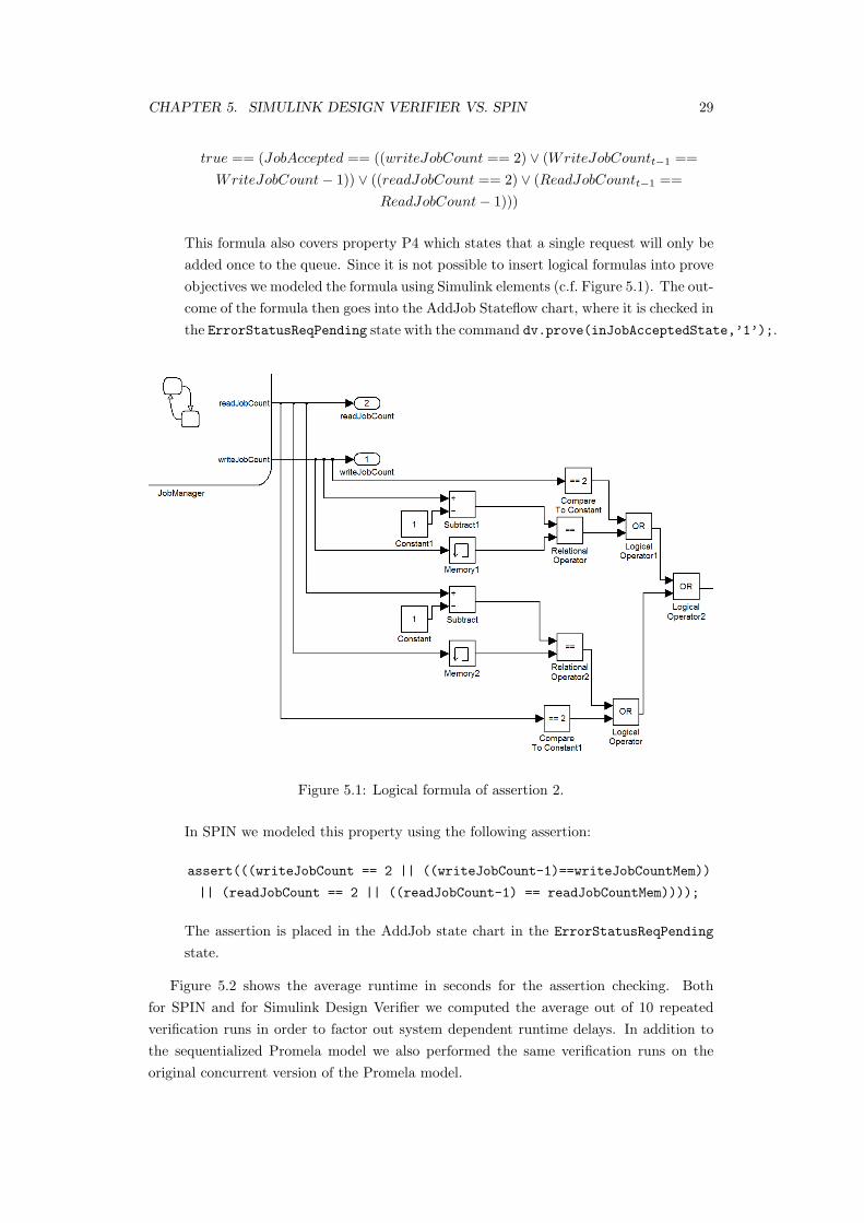
This formula also covers property P4 which states that a single request will only beadded once to the queue. Since it is not possible to insert logical formulas into proveobjectives we modeled the formula using Simulink elements (c.f. Figure 5.1). The out-come of the formula then goes into the AddJob Stateflow chart, where it is checked inthe ErrorStatusReqPending state with the command dv.prove(inJobAcceptedState,’1’);.
Figure 5.1: Logical formula of assertion 2.
In SPIN we modeled this property using the following assertion:
The assertion is placed in the AddJob state chart in the ErrorStatusReqPending
state.
Figure 5.2 shows the average runtime in seconds for the assertion checking. Bothfor SPIN and for Simulink Design Verifier we computed the average out of 10 repeatedverification runs in order to factor out system dependent runtime delays. In addition tothe sequentialized Promela model we also performed the same verification runs on theoriginal concurrent version of the Promela model.
CHAPTER 5. SIMULINK DESIGN VERIFIER VS. SPIN 30
Property Tool and Model Runtime (sec.) Property satisfied
P1.Simulink Design Verifier 2.308 yes
SPIN sequential version 0.0013 yes
SPIN concurrent version 0.0166 yes
P3/4.Simulink Design Verifier 3.19 yes
SPIN sequential version 0.0019 yes
SPIN concurrent version 0.0198 no
P1 & P3/4.Simulink Design Verifier 3.623 yes
SPIN sequential version 0.0022 yes
SPIN concurrent version 0.0385 P1. yes P3/4. no
Figure 5.2: Runtime comparison for assertion checking
5.1.2 Deadlock Checking
A deadlock occurs when concurrent processes are waiting for each other or a shared resourcein a cyclic fashion. As indicated earlier, we have one model variant in which writing anew job to a full queue will result in a blocking of the system. SPIN detects the resultingdeadlock and produces an error trail leading into the deadlock state.
Simulink Design Verifier does not provide for deadlock detection. If one forces theSimulink simulation environment into the corresponding deadlock state it will be stuck inthat state and wait for input.
5.1.3 Temporal Property Checking
The remaining properties P2, P5 and P6 can not be modeled as assertions since they assertproperties of temporal contexts. The verification of temporal properties that cannot beencoded in assertions is beyond the capabilities of Simulink Design Verifier. We are hencerestricted to SPIN in order to verify these properties. The properties are modeled usinglinear temporal logic (LTL) [22] in the following way:
� Property P2 states that if a request is pending, it will eventually be added to thequeue. We capture this with the following LTL formula:
�(reqPending → (♦reqAccepted))
The proposition reqPending holds if the value of the variable NvM_Signals is set to2 or 4, which is the case if a write or read request is pending. reqAccepted holdsif the value of the variable JobAccepted is true and this is the case if a job wasadded to the queue. Translated into natural language the formula expresses that itis always the case that if reqPending holds, it implies that eventually reqAccepted
will hold. As expected the property was proven satisfied by our model using SPIN.
� Property P5 states that if a request was added to the queue, it eventually will beprocessed. We capture P5 using the following formula:
CHAPTER 5. SIMULINK DESIGN VERIFIER VS. SPIN 31
�(reqAccepted→ (♦reqProcess))
reqAccepted is the same proposition as in the previous LTL formula. reqProcess
holds if the job scheduler is in a state in which either a read or a write request is beingprocessed. To represent this proposition in the Promela model we introduced anauxiliary variable called processing, which is set to 1 upon entry into a processingstate, and to 0 upon exit. The result of the SPIN verification was that the LTLformula is not satisfied by the model. An analysis of the SPIN counterexamplerevealed that the cause for this violation is not located inside the model, but inenvironment behavior that potentially violates fairness. As already explained, theenvironment behavior nondeterministically sends a read request, a write requests orstarts the job processing. Because of this nondeterminism it is possible, that thejob processing is never started and therefore the proposition reqProcess will neverhold. For a second run, we changed the environment model to the deterministicsequence send write request, start job processing, send read request and start fromthe beginning. Now the property was satisfied.
� The LTL formula
�(reqProccess→ (♦decrement))
was used to capture property P6 which states that if a request was processed, it willbe removed from the queue. The variable decremented is set to 1 if the job wasremoved from the queue, and it is set to 0 when the state is left. The propositiondecrement holds, if decremented is 1. reqProcess is the same like in the previousLTL formula. This property is also satisfied by our model.
Figure 5.3 shows the average runtime in seconds for the LTL property verification basedon the sequentialized and the concurrent Promela model.
Property Tool and Model Runtime (sec.) Property satisfied
P2.SPIN sequential version 0.004 yes
SPIN concurrent version 0.015 no
P5.SPIN sequential version 0.015 yes
SPIN concurrent version 0.015 no
P6.SPIN sequential version 0.015 yes
SPIN concurrent version 0.015 yes
Figure 5.3: Runtime comparison for LTL verification.
The property violations of P2 and P5 are caused by an unexpected interleaving ofenvironment and system actions. The common cause is that the environment starts a newcommand before the processing of the previous command has been completed.
CHAPTER 5. SIMULINK DESIGN VERIFIER VS. SPIN 32
5.1.4 Scaling of the Model
So far, we only compared Simulink Design Verifier and SPIN with one relatively smallmodel. To see how the runtime relates to the size of the model, we added a third and afourth queue to the model. This change would be necessary if one wants to model morethan two priorities. We verified Property 1. and Property 3/4. with 2 queues, with 3queues and with 4 queues. As can be seen in Figure 5.4 the Verification with SimulinkDesign Verifier takes noticeable longer while in SPIN the runtime for the sequential modelremains the same and the runtime for the concurrent model doubles from 3 queues to 4queues but is still smaller then 0.1 seconds.
Number of queues Tool and Model Runtime (sec.) Property satisfied
2 queuesSimulink Design Verifier 3.623 yes
SPIN sequential version 0.0022 yes
SPIN concurrent version 0.0385 P1. yes P3/4. no
3 queuesSimulink Design Verifier 19.065 yes
SPIN sequential version 0.002 yes
SPIN concurrent version 0.0201 P1. yes P3/4. no
4 queuesSimulink Design Verifier 26.789 yes
SPIN sequential version 0.0016 yes
SPIN concurrent version 0.0836 P1. yes P3/4. no
Figure 5.4: Runtime comparison for different number of queues
5.2 Qualitative Comparison
The following appear to be central aspect to the qualitative comparison of verifying systemproperties using SPIN and Simulink Design Verifier:
� We observed a significant discrepancy between the concurrent software architecturethat we were modeling and the deterministic execution semantics that Simulinkimposes. In applications like the NVRAM manager the capabilities of SPIN to dealwith concurrency and to reveal concurrency related bugs appear to be far superiorto the capabilities of Simulink Design Verifier.
� Simulink Design Verifier and SPIN allows for the checking of assertions. However,Simulink Design Verifier does not allow for expressing properties that go beyondassertion checking and which require a formalization using temporal logic formulae orequivalent mechanisms. Notice that according to [23] temporal properties followingthe response pattern, as we use here to capture P2, P5 and P6, belong to the mostfrequently used properties in practice.
� Simulink Design Verifier automatically closes the system against its environment,while in SPIN it is necessary to incorporate the environment into the model, which
CHAPTER 5. SIMULINK DESIGN VERIFIER VS. SPIN 33
requires extra modeling effort, but hives the user the chance to control the environ-ment behavior.
� The translation from the limited subset of Simulink constructs used in the NVRAMexample to VIP was fairly straightforward.
� Both Simulink Design Verifier and SPIN provide counterexamples, if a property isviolated.
� The author of this thesis was very familiar with AUTOSAR and the NVRAM com-ponent, had a moderate amount of using Matlab/Simulink and SPIN, but was newto LTL model checking and the use of the Simulink Design Verifier. He estimatedthe effort for the different modeling and verification tasks as follows (given in PersonDays (PD)):
– Editing of the original Simulink NVRAM model: 10 PDs.
– Editing of the abstracted Simulink NVRAM model used in the verification: 2PDs.
– Familiarization with VIP and editing of the VIP models: 2 PDs.
– Property formalization and performing Simulink Design Verifier verificationruns for properties P1, P3 and P5: 2 PDs.
– Property formalization and performing SPIN verification for all 6 properties: 3PDs.
It can be concluded that the use of SPIN certainly requires additional effort, which onthe other hand gives access to verification capabilities that Simulink Design Verifierdoes not possess.
An overview of the qualitative comparison is also given in Figure 5.5.
This case study cannot claim any form of empirical validity, since just one problem in-stance has been investigated. We also limited our considerations to the relatively simpleSimulink language constructs that were used in our case study. While other researchersalso consider a limited scope of the Simulink language, our conclusions regarding the goodcorrespondence between the Stateflow and the VIP/Promela model may be invalid in casea different fragment of Simulink / Stateflow is considered. However, we are confident thata large portion of Simulink and Stateflow can easily be interpreted, not at least due tothe results in [14]. Although our results in 5.1.4 indicate that SPIN will remain superiorin terms of verification runtime for assertional checking, if the size of the model grows,we have not investigated how this advantage develops as the model becomes semanticallymore complex.
Chapter 6
Conclusion
6.1 Conclusion
We have presented a case study in which we compared the use of the Simulink DesignVerifier and the SPIN model checker in the verification of important properties of theAUTOSAR NVRAM component. The quantitative comparison of both approaches ishampered by the unavailability of statistics regarding the verification run of SimulinkDesign Verifier. In terms of runtime SPIN appears to be superior for the problem instancesthat we considered. From a qualitative perspective, SPIN appears to be more suitable insupporting the concurrent nature of the NVRAM software than Simulink Design Verifier.SPIN is is also able to verify both assertional and temporal properties, while SimulinkDesign Verifier can only check assertions. Unlike SPIN, Simulink Design Verifier does notrequire a system model to be closed, which saves modeling effort compared to SPIN. Inconclusion we can say, that the effort for translating the NVRAM Manager to VIP haspaid off. Not only because SPIN was superior in terms of runtime, but but also becauseit was the only way to verify all properties we had selected for verification.
Our case study addressed a component that can be classified as belonging to generalsystem infrastructure that the AUTOSAR architecture defines. In further research we willinvestigate whether for other such components an equally straightforward and well scalingtranslation from a limited fragment of the Simulink language into VIP and/or SPIN ispossible. We will then consider an integrated tool environment, in which models andverification results can be exchanged amongst the components Simulink, VIP and SPIN.
35
Chapter 7
Appendix
7.1 CD
All models used for this bachelor thesis are stored on the attached CD. In addition theCD comprises a digital copy of this bachelor thesis.
36
CHAPTER 7. APPENDIX 37
7.2 Measurements
Figure 7.1: Measurements for property 1.
Figure 7.2: Measurements for property 3/4.
Figure 7.3: Measurements for property 1 & property 3/4.
CHAPTER 7. APPENDIX 38
Figure 7.4: Measurements for property 1 & property 3/4 with 3 queues.
Figure 7.5: Measurements for property 1 & property 3/4 with 4 queues.
Bibliography
[1] Hamon, G., Rushby, J.: An operational semantics for stateflow. Int J Softw Tools Technol
Transfer 9 (2007) 447–456
[2] McMillan, K.: Symbolic Model Checking. Kluwer Academic (1993)
[3] Cimatti, A., Clarke, E., Giunchiglia, E., Giunchiglia, F., Pistore, M., Roveri, M., Sebastiani,
R., Tacchella, A.: Nusmv 2: An opensource tool for symbolic model checking. In: Proc.
CAV 2002. (2002)
[4] Holzmann, G.J.: The Spin Model Checker: Primer and Reference Manual. Addision–Wesley
(2003)
[5] Kamel, M., Leue, S.: VIP: A visual editor and compiler for v-promela. In: Proc. TACAS
2000. Number 1785 in Lecture Notes in Computer Science, Springer Verlag (2000) 471–486
[6] Andersson, G., Bjesse, P., Cook, B., Hanna, Z.: A proof engine approach to solving combina-