64
University of Miskolc Faculty of Materials Science and Engineering MSc Thesis Thomas Azane 2019
University of Miskolc
Faculty of Materials Science and Engineering
MSc Thesis
Thomas Azane
2019

University of Miskolc
Faculty of Materials Science and Engineering
Institute of Physical Metallurgy, Metal forming and Nanotechnology
Production and Properties of High Temperature Low Sag conductors
Made by
Thomas Azane
Supervised by
Dr. Péter Barkóczy
2019

i
Table of content
Table of content i
Acknowledgement iv
Abbreviation v
Abstract vi
Introduction 1
1 Electrical transmission system 2
1.1 The nature of electricity 2
1.2 The transmission grid 2
1.3 Purpose of transmission 4
1.4 Transmission line components 4
1.4.1 Towers 4
1.4.2 Rows 5
1.4.3 Electrical discharge or corona effect 6
2 Overhead bare conductors 6
2.1 Conventional types of conductors 6
2.1.1 All aluminum alloy conductor(AAAC) 7
2.1.2 Aluminum conductor, alloy reinforced(ACAR) 8
2.1.3 Aluminum conductor steel reinforced (ACSR) 9
2.2 Limiting loss of tensile strength 10
2.3 Composite conductors 11
2.4 High temperature low sag conductors 12
2.5 High temperature conductors (low loss conductors) 13
2.5.1 TACSR (thermal resistant aluminum alloy steel reinforced) 13
2.6 Low loss conductors 14
2.6.1 GTACSR/ ZGTACR (thermal/ super thermal resistant aluminum alloy
conductor steel reinforced) 14
2.6.2 ACCC (aluminum conductor composite core) 15
2.6.3 ZTACIR (super thermal resistant aluminum alloy invar reinforced) 16
2.6.4 ACSS (aluminum conductor steel supported) 16
2.7 Conductor material 17

ii
3 Conductor behaviors 19
3.1 Current carrying capacity (ccc) 19
3.2 Sag tension calculation 20
3.3 Conductor properties 22
3.3.1 Ultimate tensile strength (UTS) 22
3.3.2 Cross sectional area 23
3.3.3 Modulus of elasticity 23
3.3.4 Linear thermal expansion coefficient 24
3.3.5 Unit resistance 25
3.4 Conductor comparison 26
4 Experimentation and result analysis 28
4.1 Introduction 28
4.2 Mechanical properties testing and analysis of the conductor 28
4.2.1 ACSR stress-strain testing 29
4.2.1.1 Sample testing of ACSR conductor 30
4.2.1.2 Stress – strain test of ACSR conductor type 434-al1/56-st1a and
183-al1/43-st1a 30
4.2.1.3 Description of the test 30
4.2.1.4 Results of the test 32
4.2.1.5 Rated tensile strength of ACSR 34
4.2.2 Sample testing of ACCC conductor and analysis 37
4.2.2.1 Strain –stress test 37
4.2.3 ACSS sample testing and analysis 39
4.2.3.1 Strain-stress test 39
4.2.3.2 Test method and parameters 40
4.2.3.3 Bird caging effect of ACSS conductor 44
4.2.4 Invar core conductors 44
4.2.5 Experiment and analysis on the gap type conductor 45
4.3 High temperature low sag test and analysis 47
4.3.1 Thermal knee point temperature 52
Summary 54

iii
References 56

iv
ACKNOWLEDGEMENT
I thank God for giving me the strength and courage, and the ability to overcome difficulties to
complete this thesis work.
I would also like to express my special thanks to my supervisor Dr. Péter Barkóczy for his
guidance, encouragement and help, he has given me throughout this project and to Fux Zrt
company as a whole for given me such opportunity to do internship in their premises.
My thanks and appreciation also goes to Prof. Dr. Valéria Martinger, the head of the Institute of
Physical Metallurgy, Metal forming and Nanotechnology for her continuous support and care
during my studies at the department.
To Dr. Katalin Voith for her unconditional help and patience with me during my studies at the
Faculty.
My sincere thanks also to all my professors at the department and lab workers who helped me
with the advices and guidance for the period of the studies.
I also thank my parents and friends for their positive support. This accomplishment would not
have been possible without their support.
Thank you.

v
ABBREVIATION
AAAC – All Aluminum Alloy Conductor
ACAR – Aluminum Conductor Alloy Reinforced
ACCC – Aluminum Conductor Composite Core
ACSR – Aluminum Conductor Steel Reinforced
ACSS – Aluminum Conductor Steel Supported
CCC – Current Carrying Capacity
CTC – Composites Technology Cooperation
CTE – Coefficient of Thermal Expansion
EC – Electrical Conductor grade
EHS – Extra High Strength Steel
GTACSR – Gap type TAL Aluminum Alloy Conductor Steel Reinforced
HS Steel - High Strength Steel
HTLS – High Temperature Low Sag Conductors
IACS – International Annealed Copper Standard
IEC – International Electrotechnical Commission
KPT – Knee Point temperature
RBS – Rated Breaking Strength
ROW – Right of Way
TACIR – TAL Aluminum Alloy Conductor Reinforced with an Invar Steel Core
TACSR – TAL Aluminum Alloy Conductor Reinforced by a Conventional Stranded Steel Core
TAL – Thermal Resistant Aluminum
ZTAL – Super Thermal Resistant Aluminum

vi
ABSTRACT
If the electric energy demand suddenly increases the reconductoring is the only one possibility
to supply the necessary electric energy. In this case the application of the HTLS conductors gives
the best result.
The increase of transmission line thermal ratings by reconductoring using High Temperature Low
Sag (HTLS) conductors is a comparatively new technology introduced to transmission expansion.
High Temperature Low Sag (HTLS) conductors are introduced into the electricity transmission
systems by the conductor manufacturers, with the aim of solving some of the disadvantages
shown by conventional overhead conductors such ACSR (All Aluminum Conductor Steel
Reinforced). Compared to conventional conductors, HTLS conductors have some of the improved
electrical and mechanical characteristics, whereby employing these conductors in overhead
transmission lines, some of the complex issues related to power transmission could be resolved.
A special design allows HTLS conductors to operate at high temperatures (200-250oC), thereby
allowing passage of higher current. The higher temperature capability increases the steady state
and emergency thermal ratings of the transmission line.
In this project we introduce the materials used in the HTLS conductors, and compare the
properties of the conductor based on the materials. Additionally, this project introduces the
specialties of the production originated to the special properties of the materials.

1
INTRODUCTION
Nowadays the utilities frequently meet an extra electric power demand in developing industrial
areas or residential areas. When this demand is larger than the capacity of the electrical line, the
operating temperature of the conductors increases more than the standardized limit.
The high voltage and middle voltage overhead lines mostly built by ACSR conductor. ACSR
conductors contains stranded steel core and stranded cold drawn aluminum wires. In this
construction the strength of the aluminum wires plays a significant role in the strength and
mechanical behavior of the whole conductor. Long term operation over the maximal operating
temperature means an annealing on the aluminum wires. During the annealing the aluminum
wires continuously lose their strength, and there is a risk of the breakage, additionally due to the
high temperature the sag of the conductors increasing extremely which causes operational
problems (phase faults, short circuits, accidents).
In that case the utilities can replace the line or can build another. Both of them are long and
expensive process. The lines have to be planed, the utility have to buy the field under the new
towers, the legislation process too long. This process cannot solve the mentioned problem in
short term. The HTLS (high temperature low sag) conductors were developed to solve this
problem. If it’s possible a simple reconductoring without the strengthening of the towers is
enough. This means the replacement of the conductor which faster process than a new line
building or a total reconstruction. The common feature of this conductors, that the maximal
operating temperature is higher than an ACSR conductor, the sag value remains low at higher
temperatures and contains special materials.
Recently more and more line reconductoring used ACCC conductor which is a protected
conductor of CTC Global company. The ACCC conductor contains a carbon fibre reinforced
composite core, and annealed trapezoidal shaped aluminum wires are stranded on it. Due to the
increasing demand CTC Global search for cable manufacturers who can produce this type of
conductor in high quality, FUX company, is the contractual producer partner of CTC Global in
Eastern-Europe, but FUX Company regularly produce other HTLS conductors as ACSS and TACIR.

2
It is important to compare this types of HTLS conductors according to the properties and
production to present clearly the advantages of the conductors from the producer point of view.

3
1 ELECTRICAL TRANSMISSION SYSTEM
1.1 The Nature of Electricity
Electricity must be used as it is generated. Unlike other commodities, there is very little ability to
store electricity. Because of the instantaneous nature of the electric system, constant
adjustments must be made to assure that the generation of power matches the consumption of
power. The electric system we have grown to depend on it very complex and dynamic, constantly
adjusting to meet changing needs.
The amount of power on any electric line at any given moment depends on generation
production and dispatch, customer use, the status of other transmission lines and their
associated equipment, and even the weather. The transmission system must accommodate
changing electricity supply and demand conditions, unexpected outages, planned shutdowns of
generators or transmission equipment for maintenance, weather extremes, fuel shortages, and
other challenges [1].
1.2 The Transmission Grid
The electrical transmission system is more complex and dynamic than other utility systems, such
as water or natural gas. Electricity flows from power plants, through transformers and
transmission lines, to substations, distribution lines, and then finally to the electricity consumer.
Fig. 1 Simplified Diagram of the Electric System [1]

4
1.3 Purpose of Transmission
Transmission lines are essential for three reasons [2]:
• To transmit power from a water power site to a market. These may be very long and
justified because of the subsidy aspect connected with the project,
• For bulk supply of power to load centers from outlying steam stations. These are likely
to be relatively short,
• For interconnection purposes, that is, for transfer of energy from one system to another
in case of emergency or in response to diversity in system peaks.
1.4 Transmission Line Components
1.4.1 Towers
Transmission towers are the most visible component of the bulk power transmission system.
Their function is to keep the high-voltage conductors separated from their surroundings and from
each other. Higher voltage lines require greater separation [3].
Figure 2 shows a lattice-type tower with a single-circuit 765-kV line. A close look at the figure
reveals twelve conductors strung from insulators suspended on the crossbar, but this is a single-
circuit line. In addition, some high-capacity circuits at up to 345 kV use multiple (bundled)
conductors for each phase rather than a single larger conductor. The lattice tower in Figure 2
uses groups of four conductors to carry each of the three phases. Above 345 kV, bundled
conductors are normally used to reduce corona discharge [2].

5
Fig.2 Lattice (left) and Monopole (right) Towers [2]
1.4.2 ROWs
A ROW is a largely passive but critical component of a transmission line. It provides a safety
margin between the high-voltage lines and surrounding structures and vegetation. Failure to
maintain an adequate ROW can result in dangerous situations, including ground faults. The width
of the ROW is determined by voltage, projected maximum safe distance from conductors,
maximum sags and swings [4].
Fig.3 ROW [4]
6
1.4.3 Electrical Discharge or Corona Effect
Corona effect is the electrical breakdown of the air near high voltage conductors into charged
particles. Corona can cause audible noise and radio and television interference, electromagnetic
interference, insulation damage, etc. Corona from transmission lines can create buzzing,
humming, or crackling [4].
2 OVERHEAD BARE CONDUCTORS
A variety of conductor compositions and constructions are currently in use to meet a variety of
specific requirements. In the early years of the industry, copper was used almost exclusively
because of its high electrical conductivity, but cable diameters with copper were determined
more by the need for mechanical strength than by the need for improved conductivity.
The low strength-to-weight ratio of copper limited the acceptable span length (distance between
towers). Aluminum, with its higher strength-to-weight ratio, was introduced as an alternative to
copper, allowing for greater span lengths. Though copper has higher conductivity than aluminum,
the lower density of aluminum gives it a conductivity-to-weight ratio twice that of copper [3].
The choice of conductor material, size and design must be take into consideration such items as:
• Ampacity (current carrying capacity)
• Voltage stress at the conductor
• Voltage regulation
• Conductor losses
• Bending radius and flexibility
• Overall economics Material considerations
• Mechanical properties
2.1 CONVENTIONAL TYPES OF CONDUCTORS
Bare overhead conductors are usually classified as homogeneous or non-homogeneous.
Homogeneous conductors are those in which the individual strands of wire comprising the cable
are of the same material. Homogeneous conductors manufactured with relatively pure aluminum

7
are called all-aluminum conductors (AAC); those manufactured with an aluminum alloy are called
all-aluminum-alloy conductors (AAAC) [5].
Non-homogeneous conductors consist of a mixture of different wire materials. The most
common type of bare overhead phase conductor is a non-homogeneous wire consisting of
aluminum strands covering a steel core. This conductor is called aluminum conductor, steel-
reinforced (ACSR).
Non-homogeneous conductors possess properties that reflect the individual properties and
relative percentages of the different materials forming the composite cable. Due to the
stranding-induced helical form of the individual strands, both types of conductors exhibit lower
composite rated breaking strength (4 to 11%), greater weight and higher electrical resistance per
unit length of conductor (2 to 4%) than would be obtained if all the component strands were
parallel [6].
The most common conventional types of conductors are:
• Aluminum Conductor Steel Reinforced (ACSR)
• All Aluminum Conductor(AAC)
• All Aluminum Alloyed Conductor(AAAC)
2.1.1 All Aluminum Alloy Conductor(AAAC)
For transmission lines strung with ACSR, design for relatively low temperature operation (50 to
65 oC), restringing with AAAC can offer a significant improvement in thermal rating. AAAC
conductors have a higher strength to weight ratio than ACSR and, if strung to a similar percentage
of rated breaking strength (RBS), can be rated for higher temperature operation than ACSR,
without exceeding design sags [7].
It should be noted that however that, stringing to a similar percentage of RBS would result in a
much higher ratio of horizontal tension(H) to unit weight of conductor(w), which can cause
problems for lines sensitive to Aeolian vibration [8].
8
The alloy used in AAAC is most commonly a heat treatable aluminum magnesium silicon alloy
designated by IEC 60104. There are many tempers available, varying in strength and conductivity.
Conductivities range between 52.5% and 57.5% IACS (EC grade aluminum has a conductivity of
61.5% IACS), while the strength vary between 250MPa and 330MPa [7].
As a rule of thumb, the higher the conductivity of the alloy, the lower the strength and vice versa.
Where AAAC can be strung at a similar percentage of RBS to ACSR, thermal rating increases of up
to 40% can be achieved with a conductor of the same diameter and 50% with a conductor of the
same weight. This may be requiring additional mechanical damping since the H/w ratio of the
AAAC will be higher than ACSR that it replaces. There are no ferromagnetic or transformer effect
losses with AAAC [7].
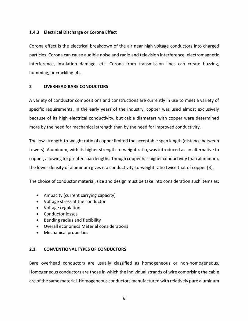
AAAC generally has good corrosion performance. The lack of a steel core removes the possibility
of galvanic corrosion taking place, such as is possible in ACSR. However, corrosion is still possible,
especially in coastal areas and it is often standard practice to use greased AAAC to prevent
corrosion by salt aerosols.
Fig. 4 AAAC Conductor [9]
2.1.2 Aluminum Conductor, Alloy Reinforced(ACAR)
ACAR combines strands made from aluminum alloy, typically the same as that used for AAAC,
and EC grade aluminum. This allows the properties of the conductor to be optimized for a

9
particular application. By increasing the amount of EC grade aluminum used, the conductivity of
the conductor increased, though at the expense of strength.
Likewise, if the number of alloy strands is increased, the mechanical strength of the conductor is
increased at the expense of conductivity again. Again, as with AAAC, the benefits of using ACAR
conductors to replace ACSR conductors will depend on allowable stringing tensions [10].
2.1.3 Aluminum Conductor Steel Reinforced (ACSR)
ACSR conductor, which is widely used for transmission lines, is a concentrically stranded
conductor. It consists of a relatively non-conducting steel core. The steel core is galvanized to
prevent corrosion.
The aluminum wires which covers the steel core is a hard drawn 1350 aluminum wire with H19
temper [11]. The maximum operating temperature of ACSR conductors is 100ᵒC [12]. Above this
temperature, annealing of the aluminum wires takes place which results in rapid degradation of
tensile strength of the conductor. The air between the conductor strands acts as an insulating
material which impedes the conduction of heat to the outer surface of the conductor. This
significant resistance to the radial heat transfer can produce a radial temperature gradient within
the conductor.
Morgan [13] and Harvey [14] have investigated the loss of tensile strength of overhead
transmission conductors due to annealing. Both provide empirical formulas to calculate the loss
of strength for ACSR conductors with temperature and time.
Fig. 5 Typical ACR Conductor [13]

10
2.2 LIMITING LOSS OF TENSILE STRENGTH
For conductor temperatures above 90 oC, hard-drawn aluminum and copper strands will lose
significant tensile strength(anneal) over time. Copper wires may also anneal at lower
temperatures although the rate is very slow.
Temperature below 300 oC do not affect the tensile strength of steel strands. Aluminum
conductors having a steel core(ACSR) also experience loss of composite strength if operated
above 90 C but, since the strength of the steel core is unaffected, the reduction in tensile strength
in the aluminum strands is of less concern than for phase conductors made entirely of aluminum
or copper strands [7].
Aluminum strands made from rod made by the continuous casting process are less susceptible
to annealing than those drawn from rolled rod. Since the rod source for an existing stranded
conductor may be unknown, it is conservative to assume rolled rod as the source of aluminum
wires [7].
Annealing of 1350-H19 Hard Drawn Aluminum Wire
Fig. 6 Typical annealing curves for aluminum wires, drawn from rolled wire of a diameter
typically used in transmission conductors [15]
The conductor temperature must remain above 90oC for an extended period of time for the
reduction of strength to become significant. For example, with reference to figure 15, an all-

11
aluminum conductor at 100oC must remain at that temperature for 400 hours to lose 5% of its
tensile strength. This loss of tensile strength is cumulative over the life of the line so routine
emergency operation at 100oC may be unacceptable over time even though individual events
may persist for no more than a few hours.
As the conductor temperature increases, the rate of annealing increases rapidly. At 125oC, an all-
aluminum conductor will lose 5% of its tensile strength in only 30 hours. For aluminum strands
drawn from continuous cast rod, the loss of strength in these two high temperature- time
combinations is negligible. The loss in tensile strength at temperature above 100oC (above 125oC
for wire from continuous cast rod) may be limited by using limited time ratings where high
current is allowed only for brief periods of time. As noted in many references, the presence of a
steel core, which does not anneal reduces the loss of strength for ACSR conductors.
2.3 COMPOSITE CONDUCTORS
Composite cores have higher mechanical strength and lower coefficients of thermal expansion
when compared with the steel core used in traditional ACSR or ACSS conductors. With line ratings
current carrying capacity at maximum operating temperature, dependent on the line clearance
to ground (sag), these properties allow for a significant rating increase over ACSR or ACSS
conductors.
Metal matrix composite conductor is a non-homogeneous conductor consisting of high
temperature aluminum zirconium strands covering a stranded core of fiber reinforced composite
wires. The ACCR core consists of Al2O3 fibers, about 10 μm in diameter, in metallic matrix
(aluminum) alumina fibers in an aluminum matrix [6]. There is no dielectric barrier in the ACCR
core. Therefore, the ACCR core will carry some current, although a majority of it will flow in the
aluminum conductors owing to the skin effect.
Carbon composite conductor incorporates a lightweight advanced core made of continuous glass
and carbon fibers with polymer resin over which a trapezoidal shaped aluminum wires are
wrapped. The ACCC core evaluated consists of carbon fibers surrounded by a sheath of glass

12
fibers all bonded with an organic epoxy resin. The fiberglass sheath serves as a barrier and
prevents corrosion by separating two dissimilar materials (carbon and aluminum) [6].
The fundamental difference in these conductors is the construction of the core. Both the
composite core and the outer aluminum-zirconium (Al-Zr) strands contribute to the overall
conductor strength. Each core wire contains thousands of high strength micrometer sized fibers.
The fibers are continuous, oriented in the direction of the wire. Both the carbon composite
conductor and the aluminum metal matrix conductor are dramatically superior to the
conventional ACSR conductors of comparable diameter. Both cores employ either circular or
trapezoidal aluminum conductors as shown in the figures below:
Fig. 7 Aluminum Conductor Composite Reinforced Fig. 8 Aluminum Conductor Carbon
(Inspired by Fux Zrt Company) Composite( Inspired by Fux Zrt Company)
2.4 HIGH TEMPERATURE LOW SAG CONDUCTORS
For more than hundred years, ACSR has been the main candidate for overhead transmission lines.
There are occasions where AAAC and ACSR/AS conductors are used in construction of overhead
lines mainly to get additional corrosion protection for conductors.
However, ACSR is still the most preferred choice for transmission line construction by most of the
designers in the world. When it comes to ACSR, thermal sag is considered one the major
disadvantages. With the increase in temperature, the expansion of the conductor gets increased
as a result of the increase in current.

13
In ACSR conductors, the maximum continuous operating temperature that could be achieved is
around 90oC [12], If the conductor is operated at temperatures above this value, it is more
susceptible to lose its tensile strength over time. This phenomenon is known as annealing. This
will result creep elongation in lines and safety clearances will get violated.
Therefore, manufacturers have come up with another technology called Low Loss Conductors
where it can be operated at higher temperatures such as 150oC [16]. TACSR (Thermal Resistant
Aluminum conductor steel reinforced) is a Low Loss conductor, which is especially available in
Japanese conductor market.
2.5 High Temperature Conductors (Low Loss Conductors)
2.5.1 TACSR (Thermal Resistant Aluminum Alloy Steel Reinforced)
Its construction is similar to ACSR but EC grade outer strands are replaced with hard drawn
aluminum of heat treated Al alloy which is denoted as TAL. TACSR can be safely operated at
higher temperatures above 150°C enabling to pump more power through the conductor.
These conductors are useful when there is a need to transfer more power but restrictions on
getting ROW. To maintain its electrical and mechanical power at elevated temperatures, Al wires
are doped with Zirconium. Zr is extremely resistant to heat and corrosion. Though, TACSR is a
high temperature conductor. It is not a low sag conductor. Therefore, the use of TACSR is limited
only for new transmission line constructions [16].

14
2.6 Low Loss Conductors
2.6.1 GTACSR/ ZGTACR (Thermal/ Super Thermal Resistant Aluminum Alloy Conductor Steel Reinforced)
Fig. 9 Gap Conductor Formation [7]
This conductor is commonly known as Gap type Conductor. That is because there is a gap in
between outer and inner layers. Outer layer is made of Zirconium doped hard drawn aluminum
alloy. Outer most layer strands are circular in shape and the strands in one layer below are
trapezoidal in shape. Annular gap is filled with thermal resistant grease. Inner core is made of
High strength steel. Steel core and aluminum core can move independently to each other due to
the presence of grease [17, 18, 19].
Japanese are the pioneers of Gap conductors. Currently there are many other utilities who are
manufacturing these Gap conductors. Main advantage of these Gap conductor is that their ability
to operate at high temperatures without having higher sag values as in the case of conventional
and low loss conductors.
GTACSR conductors can be operated at 150°C (TAL) and ZGTACSR conductors can be operated at
210°C (ZTAL). Stringing requirements of these conductors are different that of conventional
conductors. Two stage stringing is used with Gap conductors where 70% of the conductor is
tensioned together with Al and steel core and the rest is tensioned on the steel core along. By
doing that, conductor sag can only be subjected to the expansion behavior of steel above knee
point temperature [7].

15
Knee Point Temperature (KPT) is the temperature that the complete conductor tension is taken
by the steel core. Gap conductor has comparatively very low KPT.
2.6.2 ACCC (Aluminum Conductor Composite Core)
Fig. 10 ACCC Formation (Source: Fux zrt Company)
Core of the ACCC conductor is made of hybrid carbon and glass fiber composite core which
utilizes a high temperature epoxy resin matrix to bind hundreds of thousands of individual fibers
into a unified load bearing tensile member. The central carbon fiber core is surrounded by high
grade boron free glass fibers to improve flexibility and toughness. Additionally, it prevents
galvanic corrosion between carbon fiber core and aluminum strands. Aluminum strands are
made of Annealed Aluminum (1350-O) which has a higher conductivity compared to Hard Drawn
Aluminum. Aluminum strands are trapezoidal in shape [20].
As in the case of Gap conductors, ACCC also has a very low KPT which helps to have lower sag
values with increasing temperature. Thermal expansion of the core is negligible compared to the
other types of conductors. ACCC conductors can safely be operated up to 180°C. These
conductors require special installation methods and careful handling of the conductor.
16
2.6.3 ZTACIR (Super Thermal Resistant Aluminum Alloy Invar Reinforced)
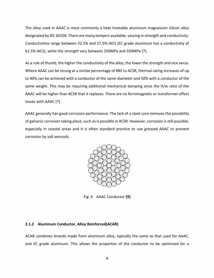
Fig. 11 ZTACIR Formation [7]
This conductor is commonly known as the Invar Conductor. Shape is more similar to ACSR/AW.
Unlike in the case of ACSR, the outer strands of Invar conductor is made of heat treated annealed
aluminum strands which can operate at elevated temperatures. The core of the conductor is
made of Aluminum Clad High strength steel which has a lower thermal expansion value. These
conductors can be operated up to 210°C [21, 22].
One of the advantages of Invar conductors is that their installation and the spares required are
more similar to ACSR. These conductors have considerably a higher KPT value, so that the low
sag performances cannot be expected at lower operating temperatures.
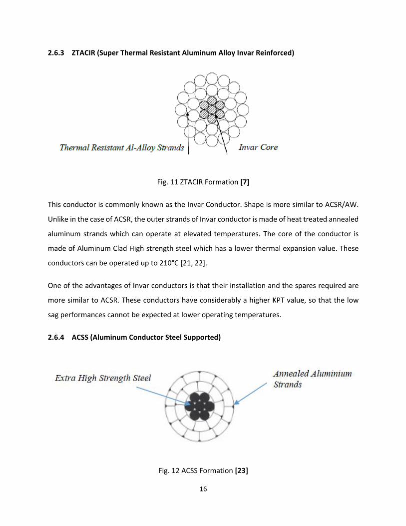
2.6.4 ACSS (Aluminum Conductor Steel Supported)
Fig. 12 ACSS Formation [23]

17
Outer strands of ACSS conductor is made of heat treated fully annealed Aluminum that has a
trapezoidal shape. Core of the conductor is made of extra high strength steel (EHS). This
conductor is very popular in USA as well as some of the European countries. This conductor can
be operated at 250°C without compromising its tensile strength. Stringing requirements of this
conductor is very similar that of conventional conductors [23, 24].
2.7 CONDUCTOR MATERIAL
All the conductors mentioned in the above clause are different to one another base on the
material being used and their formation. Conductor properties that are described such as
conductivity, unit resistance, tensile strength, thermal expansion and elasticity have gotten their
specific values base on how they are formed.
Table 1: Aluminum Conductor Material [25]
Description Type Conductivity
(% IACS)
Tensile Strength
(ksi)
Maximum
Operating
Temperature
( C)
Hard Drawn 1350-H19 61.2 23-25 90
Fully Annealed 1350-O 63 6-14 250
Thermal
Resistant
TAL 60 24-27 150
Ultra Thermal
Resistant
ZTAL 58 24-27 200
It can be seen that when the conductivity of the conductor material is increased, there is a drop
of its tensile strength. Therefore, the operating temperature of the conductor or the current

18
carrying capacity of the conductor can only be increased by compromising the strength of the
conductor material. This is the reason that conductors such as ZTACIR and ACSS, the conductors
which are capable of operating at elevated temperatures use fully annealed aluminum. However,
with the reduction of the tensile strength, material becomes softer which in turn require proper
handling during stringing.
Table 2: Core Material [25]
Description Weight (g/cm3) Modulus of
Elasticity (msi)
Tensile Strength
(ksi)
Coefficient of
Thermal
Expansion (x 10-6
/ C
HS Steel 7.78 29 200-210 11.50
EHS Steel 7.78 29 220 11.50
Aluminum Clad 6.59 23.5 160-195 13.00
Carbon Hybrid
Epoxy
0.07 16-21 330-375 1.60
Invar Alloy 7.78 23.5 150-155 3.00
Core material is responsible for providing mechanical strength for the conductor to be strung
between towers. In HTLS conductors, complete conductor tension is taken by the core material
after KPT. Therefore, it is always useful to have lower thermal expansion value in the core
material so that conductor sag will not increase rapidly with the increasing temperatures.
This is one reason, why ACCC conductors provide superior sag performances compared to other
conductors as it has a very low thermal expansion value. At the same time, it is to be noted that
conductor performances depend on many variables so that looking at a single property of the
conductor could be misleading.

19
3 CONDUCTOR BEHAVIORS
There are two major calculations carried out during the process of selecting conductor material.
• Current carrying capacity
• Sag Tension Performances
During system planning and design conductor current rating is calculated under given
environmental inputs and then Sag Tension Calculations are performed in order to identify the
clearance requirements and forces.
3.1 Current Carrying Capacity (CCC)
In this research the current carrying capacity is calculated based on IEEE 738-2006 and IEC 61597.
Conductor current rating is not something specific for the particular conductor. Current capacity
will be depending mostly on environment inputs of the area being selected.
Heat balance equation is used to calculate the CCC [32]
𝑃𝑗 + 𝑃𝑠𝑜𝑙 = 𝑃𝑟𝑎𝑑 + 𝑃𝑐𝑜𝑛𝑣 …… (1)
Pj - Heat generated by Joule effect
PSol - Solar heat gain by conductor surface
PRad - Heat loss by radiation of the conductor
Pconv - Convention Heat loss
The steady state CCC can be found as
𝐼𝑚𝑎𝑥 = √𝑃𝑅𝑎𝑑+𝑃𝑐𝑜𝑛𝑣−𝑃𝑠𝑜𝑙
𝑅𝑇 ………… (2)
Where RT is the conductor unit resistance at given temperature.

20
3.2 Sag Tension Calculation Although, the primary function of conductors is to transfer electrical load, they shall also be
strong enough to withstand the forces coming from its weight, wind and other loads when they
are strung on towers [26]
Conductor Sag is given by;
𝐷 =𝑊𝑆2
8𝑇 ………. (3)
D - Conductor sag (m)
W - Unit weight of the conductor (N/m)
T - Conductor tension at given temperature (N)
S - Span (m)
To maintain the required ground clearances, the conductor sag shall be maintained at a certain
level. Therefore, it is always preferable to have a smaller sag. One way of achieving higher ground
clearance is the use of taller towers. However, the viability of that option heavily depends on
economic factors such as steel cost, foundation cost etc. Reduction of span is also one option but
that in turn will increase the number of towers in the line.
Use of lower weight conductor is one another option of reducing conductor sag. By the use of
some of the HTLS conductors, this can be achieved and considerable amount of sag can be
reduced as illustrated in the diagram below:

21
Increase of initial tension is also one option of reducing conductor sag. however due to the fact
that higher tension conductors are susceptible for fatigue failure the initial tension is maintained
at less than 40% of the UTS of the conductor. With the increase in temperature, the tension of
the conductor will reduce. This can be found using the state equation given below;
𝐻22 [𝐻2 − 𝐻1 +
𝐸.𝐴(𝑆.𝑀𝐶1.𝑔)2
24𝐻12 + 𝐸. 𝐴. 𝑒(𝑡2 − 𝑡1)] =
𝐸.𝐴(𝐸.𝐴.𝑀𝐶2.𝑔)2
24 ……. 4
H2 - Stress at a given Temperature (N/mm2)
H1 - Initial Stress (N/mm2)
E - Modulus of Elasticity (N/mm2)
A - Conductor Cross Section (mm2)
MC1 - Initial Unit Mass (kg/m)
MC2 - Unit Mass at given Temperature (kg/m)
g - Gravitational Constant (ms-2)
e - Thermal Expansion Coefficient (oC-1)
t1 - Initial temperature (oC)
t2 - Operating Temperature (oC)
ACSR Conductor plan
HTLS Lower Tension = Same
Span but Lower Towers
HTLS Lower Tension =
Longer Spans with same
Towers

22
It can be seen that, the reduction in tension at higher temperatures can be reduced by having
lower thermal expansion coefficient. Conductors such as ACCC and ZTACIR have very lower
thermal expansion values compared to ACSR and hence the conductor sag given by these
conductors at given temperature is lower than that of ACSR.
At the same time, it is to be noted that sag tension calculation for HTLS conductors have to be
done in two stages as they have two different expansion coefficient at below and above KPT.
Normally, the expansion coefficient of the core material is lower compared to the expansion
coefficient of Aluminum material. Complete tension of the conductor is taken only by the core
above the KPT. This is one of the advantages of having lower KPT as the conductor expansion
could be kept at a lower value at higher temperature so is conductor sag.
3.4 CONDUCTOR PROPERTIES
Selection of a conductor is done based on the requirements of the specific transmission line
design. Design requirements can be categorizing as electrical, mechanical and civil. Usually all
these criterions are met after the study of relevant conductor properties.
In this project work, below mentioned properties are discussed and comparison and selection of
conductors will be analyzed based on them [27, 28, 29].
3.4.1 Ultimate Tensile strength (UTS)
UTS is the maximum stress that a conductor can withstand while being stretched or pulled before
failing or breaking. Usually, UTS is given by kilo Newton (kN). It is always preferred to have higher
UTS conductors as they can be used to obtain higher span lengths with minimum sag values.
However, in order to use higher UTS, transmission line towers shall also be capable of handling
the forces exerted by conductors. UTS at times is referred as breaking load of the conductor.
Based on the design specifications of CEB, the maximum tension that could be exerted on
conductors is 40% of the UTS of the conductor (Safety Factor of 2.5) [30].

23
For Example
UTS of a Zebra conductor = 131.9KN
Maximum working Tension = 131.9/2.5 = 52.76KN
3.4.2 Cross Sectional Area
ACSR conductors are made of two layers, named as Inner and Outer. Outer layer is made of
Aluminum strands and the inner layer is made of steel strands or aluminum clad steel strands.
Cross section of aluminum and steel are specified separately and as summation in technical
catalogues. Total cross section of aluminum or steel layers is equal to the summation of the cross
section of each strand.
For example
Zebra Conductor (54/7, 3.18mm,484.5 mm2)
54 - the total number of Aluminum strand
7 - the total number of steel strand
3.18mm – diameter of the strand
Total cross section area = 𝜋 (𝑑2
4) × (54 + 7)
=𝜋 (3.182
4) × (54 + 7) = 484.5 mm2
Cross section of the conductor directly effects the current carrying capacity of the conductor and
mechanical forces getting applied on the conductor. Higher the cross section, higher will be the
current rating and higher will be the wind forces being acted.
3.4.3 Modulus of Elasticity
Modulus of Elasticity, is the conductor tendency to be deformed elastically when a force is
applied to it. The elastic modulus of a conductor is defined as the slope of its stress-strain curve
in the elastic deformation region. Usually conductor manufacturers provide stress strain curves

24
of their products. This is given in GPa or N/mm2. Since ACSR is non homogeneous conductor, Al
layer as well as steel layer has their own modulus of elasticity values. Therefore, elastic modulus
for the complete cable is found as below [25]:
𝐸𝐴𝑆 = 𝐸𝐴𝐿𝐴𝐴𝐿
𝐴𝑇𝑜𝑡𝑎𝑙+ 𝐸𝑆𝑇
𝐴𝑆𝑇
𝐴𝑇𝑜𝑡𝑎𝑙 ……… 5
EAL - Modulus of Elasticity of Aluminum (GPa)
EST - Modulus of Elasticity of Steel (GPa)
EAS - Modulus of Elasticity of Aluminum Steel Composite (GPa)
ATotal - Total cross sectional Area (mm2)
AAL - Area of Aluminum strands (mm2)
AST - Area of Steel Strands (mm2)
3.4.4 Linear Thermal Expansion Coefficient
Linear Thermal expansion is the tendency of the conductors to change in length in response to a
change in temperature. Since ACSR conductors are made of two elements (Al and Steel), they
have two thermal expansion coefficients. However, as they are stranded together, at initial
temperatures, the expansion occurs simultaneously for the entire conductor [25].
Thermal expansion of ACSR conductor is calculated as shown below:
𝛼𝐴𝑆 = 𝛼𝐴𝐿 (𝐴𝐿
𝐴𝑇𝑂𝑇𝐴𝐿) (
𝐸𝐴𝐿
𝐸𝐴𝑆) + 𝛼𝑆𝑇 (
𝐴𝑆𝑇
𝐴𝑇𝑂𝑇𝐴𝐿) (
𝐸𝑆𝑇
𝐸𝐴𝑆) ………….. 6
αAS - Conductor coefficient of thermal expansion
αST - Steel coefficient of thermal expansion
αAL - Aluminum coefficient of thermal expansion

25
3.4.5 Unit Resistance
Unit resistance of the conductor is given by ohm per kilometers in technical catalogues of
conductor manufacturers. With the change in conductor temperature, the unit resistance of the
conductor gets varied and this variation is considered nonlinear. However still for some manual
calculations, resistance is assumed to be varied linearly. Unit resistances at 25oC and 75oC are
usually given in PLSCADD (Power Line Systems and Computer Aided Design and Drafting).
According to IEEE 738- Standard for Calculating the Current-Temperature of Bare Overhead
Conductors below formula is given to find out the resistance at given temperature [31].
𝑅𝑡 = [𝑅𝐻−𝑅𝐿
75−25] (𝑇𝑡 − 25) + 𝑅𝐿 ……….. 7
Rt - Resistance at Temperature t
RH - Resistance at 75oC
RL - Resistance at 25oC

26
3.5 CONDUCTOR COMPARISON
Table 3: Comparison of Conductors
Conductor ACSR GTACSR ZTACIR ACCC
Construction
Outer
Layer
Hard drawn
Al
Hard drawn
Al
Annealed AL Fully Annealed
Al
1350-H19 1350-H19 ZTAL 1350-O
Inner
Layer
Steel Extra High
Strength steel
Aluminum
Clad Invar
Composite
Core (Carbon
Hybrid and
glass fibre)
Core
Withstanding
temperature
170 200 300 > 300
Knee Point
Temperature
oC 75-85 32 130 35-55
Tensile
Strength
Al 23-25 23-25 24-27 6-14
Core 200-210 220 160-195 330-375
Conductivity %IACS 61 60 60 63
Max
Operating
Temperature
75-85 150-210 210-230 180
From Table 3, it can be seen that the maximum operating temperatures of HTLS conductors are
higher compared to the maximum operating temperature of ACSR. KPT of ACCC and Gap
conductors are considerably lower compared to Invar conductor. Therefore, when selecting HTLS
conductors, this has to be studied because of using Invar conductor at lower temperature will be
giving the benefit of lower sag. Therefore, in light loaded transmission lines, it is always better to

27
select a conductor which have lower KPT so that complete tension of the conductor can quickly
be subjected to the core material.
Fig. 13 KPT of Different Conductors
Figure 13 shows the change of conductor sag with its operating temperature. ACSR conductors
cannot be operated beyond its KPT as its tensile strength will start losing at elevated
temperatures. Therefore, the advantage of low sag performances cannot be achieved with ACSR.
However, since HTLS conductors can be operated at higher temperatures, they are capable of
showing low sag performances above KPT. It can be seen that with ACCC conductors, the increase
in sag above KPT is negligible.

28
4 EXPERIMENTATION AND RESULT ANALYSIS
4.1 INTRODUCTION
This project was carried out at Fux zrt company laboratory which is a joint laboratory of the
University of Miskolc and Fux zrt company. The laboratory is located at the company plant. The
company deals with the manufacturing of different types of conductors both the conventional
and the HTLS conductors for the local and abroad distribution and transmission systems. They
also deal with the manufacturing contact wires for the railway companies.
An extensive amount of conductor testing is required to understand not only the physical,
mechanical, and electrical properties a conductor offers, but more importantly, to understand
how it will perform and survive in various conditions over a period of several decades.
The thesis focus on the comparison of the conventional conductors and HTLS conductors. Four
different types of HTLS conductors namely the ACCC, ACSS, Gap and Invar core type conductors
were used for the comparison. Their mechanical properties specifically tensile strength was
measured and analyzed both in room temperature and at higher temperature. The relationship
of temperature and sag was also measured and compared. The resistance of the various
conductors was also determined experimentally. I did the same experiment for the conventional
conductor ACSR, and it properties was also compared.
4.2 MACHANICAL PROPERTIES TESTING AND ANALYSIS OF THE CONDUCTOR
The mechanical characteristics of bare overhead conductors define their sag and tension
response to external wind, ice, point loads, temperature change and time. ACCC conductors are
sufficiently different from all other conductors in their material makeup that their sag and tension
response to loads, temperature and time is equally unique. To understand these differences,
mechanical conductor characteristics are discussed in general.
When tensile load is initially applied to a new bi-material is a non-homogeneous conductor, the
load is shared by both the core and conductive strands. Over time, each material responds

29
differently to tension and temperature. As such, their load sharing will shift as a result. As will be
discussed in greater details in this part of the thesis, it reduced load or stress on the aluminum
strands serves to improve self-damping qualities at higher conductor tensions.
4.2.1 ACSR STRESS-STRAIN TESTING
To understand the stress-strain relationship, standardized stress-strain (load) and creep tests are
performed to provide information used in sag-tension calculations for line engineering. Figure 14
provides a plot of a typical ACSR Stress vs. Strain test.
Fig. 14 Aluminum Association Stress- Strain Plot of ACSR Conductor and Steel Core
Since RTS is a calculated value, it is known before the test begins, although tensile tests are
generally performed to confirm calculated values. Even though the RTS value is a calculated
value, it represents the actual breaking strength of the conductor quite well. A conductor sample
of approximately fifty feet (16 meters) in length is placed in a load frame. A small amount of
tension (~2 to 5% RTS) is applied for a brief period of time to allow for initial loose strand settling.

30
4.2.1.1 SAMPLE TESTING OF ACSR CONDUCTOR
Sample testing of the ACSR conductor were carried out in Fux zrt company laboratory which is
affiliated with the University of Miskolc. Stress– strain test of ACSR conductor type 434-AL1/56-
ST1A and 183-AL1/43-ST1A with dead end and also with wedge clamp were carried out according
to the standard EN 50182.
4.2.1.2 Stress – Strain Test of ACSR Conductor Type 434-AL1/56-ST1A and 183-
AL1/43ST1A
The Stress – Strain test of ACSR conductor type 434-AL1/56-ST1A and 183-AL1/43-ST1A was
carried according to the standard EN 50182 as follows;
• Determination of the Stress – Strain curve
• Determination of the Tensile breaking strength
4.2.1.3 Description of the Test
The test was performed on a conductor of length 10m as shown in the figure below. The loading
conditions of the test was according to the standard as follows;
The loading conditions for the test was in accordance to the standard as follows:
• Initial load of 5% of RTS was applied.
• Load of 30% of RTS was applied and held for 30 min, then released to initial load
• Load of 50% of RTS was applied and held for 1 hour, then released to initial load
• Load of 70% of RTS was applied and held for 1 hour, then released to initial load
Load of 85% of RTS was applied and held for 1 hour, then released to initial load
After then the load was continues increased until breakage occurred.

31
Table 4: Force at 5, 30, 50, 70 and 85 percent of RTS of conductor
ACSR Conductor
Type
183/43 434/56
Initial load (5%
RTS)
4.0 kN 6.7 kN
30% RTS 24.0 kN 40.1kN 0.5 hour release to
initial load
50% RTS 40.0 kN 66.8kN 1 hour release to
initial load
70% RTS 56.0 kN 93.5kN 1 hour release to
initial load
85% RTS 68.0 kN 113.6kN 1 hour release to
initial load
Table 5: List of Tools Used for the Test
Designation Manufacturer Type S/N
Dead ends - - -
Tensile machine (200kN) FUX Zrt. - C812-T0
(250113192699E)
Measuring tape Jobi 10m 13110
Caliper gauge MIB MIB
HARDENED
GX0509A1214

32
The plot of load-strain data in Figure 14 shows the three steps at the 30%, 50% and 70% holds
(IEC and EN standards require an additional hold at 85% RTS for 1 hour). At each hold, the strain
increases while the tension is held constant. Some permanent deformation (elongation) of the
conductor occurs as illustrated by the curving of the plot to the right as the load is increased. The
release of load after each hold reveals the permanent deformation, as the plot does not retrace
along the initial plot, but falls away at a constant slope each time, but further and further to the
right.
Fig.15 Test Arrangements of Stress-Strain Test and the Broken Conductor
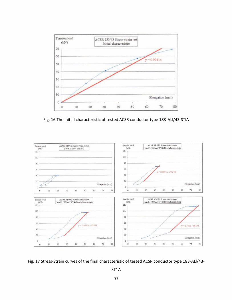
4.2.1.4 Results of the Test
The Stress – strain curves are shown in Figs
The ACSR conductor 183-AL1/43-ST1A was broken at a load of 77.1 kN (96.4 % of 79.9 kN) and
ACSR 434-AL1/56-ST1A was broken at 139.4 kN (104.3 % of 135.59 kN). The breaking loads were
higher than 95% of RTS, which is the acceptance criterion according to the relevant standard. The
conductor can be seen on the figure above after breaking.
33
Fig. 16 The initial characteristic of tested ACSR conductor type 183-ALl/43-STlA
Fig. 17 Stress-Strain curves of the final characteristic of tested ACSR conductor type 183-ALl/43-
ST1A

34
Fig. 18 The Conductors after Breaking
4.2.1.5 RATED TENSILE STRENGTH OF ACSR
The Rated Tensile Strength (RTS), sometimes referred to as Rated Breaking Strength or RBS of
conductors is defined in the USA by ASTM Standards. Other countries have their own standards
and many adopt IEC Standards. The methods for calculating RTS are not consistent in detail or
principle around the world, and thus it is important to understand how the strength of the
conductor is determined depending on the region the wire will be used in.
The RTS of ACSR is calculated as the sum of the stated strength of the aluminum strands and of
the steel strands all at 1% strain. The 1% strain limit is chosen because it safely approximates the
breaking strain of the hard (1350-H19) aluminum strands. The strength of steel core peaks at 3%
to 4% strain. Once aluminum strands begin to break, the load transfer to the steel core strands,
overloading the steel core fairly quickly. It is interesting to note that in most ACSR conductor
designs, the aluminum strands contribute to approximately 50% of the conductor’s rated tensile
strength at room temperature when the tests are conducted and the RTS calculations are made.
Figure 19 illustrates the failure mechanism of Drake ACSR. The combined aluminum/steel strand
strength plotted in blue builds to 1% strain when the aluminum strands begin to break. This
represents 100% of the conductor’s RTS. As the hardened aluminum strands yield and break, the

35
conductor’s strength drops to that of the core only (shown in red). This strength holds to
approximately 3.5% strain, when it subsequently breaks. Note that the strength of the aluminum
strands and the strength of the steel core each contribute approximately 50% to the overall
conductor’s rated strength.
Fig. 19 ACSR Stress-Strain Curve. The lower line represents the ACSR core-only (stress and strain). The upper line shows the core and aluminum stress and strain.
Figure 20 compares the stress-strain nature of a steel core and the ACCC conductor core. The
ACCC conductor core is purely elastic showing no permanent elongation up to its rupture at ~2%
strain. The steel core does not break until above 2.5% strain but begins to yield at approximately
0.6% strain.

36
Fig. 20 Steel Core & ACCC Core Comparison
Conductor testing performed at Fux Zrt and other labs show that the core of ACCC conductors
breaks very consistently at ~2% strain. Thus the ACCC conductors RTS is the sum of the stated
strengths of the aluminum strands and of full ultimate tensile strength of the core, similar to how
ACSS conductors are rated. Table 4.1 illustrates several differences between the three conductor
types. First, each conductor type will be stretched by different amounts to challenge its rated
strength. Second, the load sharing between the two materials aluminum and core is very
different between the conductor types.
Table 6: Conductor Strength and Strain Comparison
Conductor Diameter(m) Km2 Weight (N) RTS (KN) Strain at
RTS (%)
RTS
Contribution
from Core
ACSR 1.108 4028 4.8664 140.12 1 56%
ACSS 1.108 4028 4.8664 115.21 3-4 77%
ACCC 1.108 5199 4.6573 182.82 2 84%

37
The cores of the ACSR and standard ACSS use the same type of steel core sometimes with
different coatings but as defined by ASTM, the rated core strength of the lower strength ACSS
conductor is greater, but at a triple to quadruple the ACSR strain.
The core of the ACCC is twice the strength of the ACSR core but at twice the strain. The 1350-H19
aluminum of the ACSR contributes greatly to the ACSR RTS while the annealed 1350-O aluminum
of the ACSS and ACCC conductors contributes very little.
As the temperature of the conductor drops, the load in the aluminum increases so the ACSR
strength relies on the integrity of the aluminum quite a bit when it matters most. The relaxation
of the soft annealed aluminum means that it will never contribute greatly to the strength of the
ACSS or ACCC conductors so the integrity of these conductor’s strength is highly dependent on
the core.
4.2.2 SAMPLE TESTING OF ACCC CONDUCTOR AND ANALYSIS
4.2.1 STRIAN –STRESS TEST
Figure 21 shows a stress-strain curve for ACCC conductor when subjected to the same stress-
strain test protocol.
It can be seen that the fully annealed aluminum yields at a relatively low load, and then plastically
elongates. Also notice that as the load is increased, and then relaxed, it relaxes along the
conductor final modulus lines (2 and 3, 5 and 6, and 8 for example).
Thus, when the conductor was first subjected to the 30% RTS load of 54.8 kN, the aluminum was
carrying some of the tensile load. After the conductor was held at 50% RTS 91.4 kN, and then
returned to 30% RTS, it can be see that the aluminum is no longer carrying load, and all the load
is carried by the core alone. This unique aluminum load shedding will be explained in more detail
in later sections. For the core, a stress-strain curve is shown in Figure 19. Notice, that while the
core is subjected to the same testing protocol, there are no horizontal lines at each of the % RTS
values. This shows not only that the composite core is perfectly elastic; it also shows that it does
not experience any creep that would cause permanent deformation or elongation to the core.

38
Fig. 21 Typical stress-strain curve for ACCC Conductors
Figure 22 - Stress-strain curve for a composite core used in ACCC

39
If the conductor two constituent materials (conductive strands and core) were purely elastic and
exhibited no permanent elongation under load for any reason, the conductor and the core plots
would be straight lines and the plot, while the load is being applied, would be retraced as the
load is being removed. This is almost the case for the steel core up to about 0.5% strain (or
approximately 60% of the overall conductor’s RTS for ACSR), beyond that it changes due to
deformation/yielding (Figures 19and 20).
Referring to Figure 21, the slope of the unload and reload plots is the same after all three holds.
This slope is defined as the final modulus of elasticity (MOE) of the conductor, and is considered
to be a single value that is always applicable at tensions below the maximum tension that has
ever been imposed on the conductor. A review of test data for ACCC core stress-strain plots for
example shown in Figure 22 shows that it is elastic up to the point of rupture at ~2% strain (100%
RTS).
When calculating the final modulus (MOE) and coefficient of thermal expansion (CTE) of the
whole conductor, be it ACCC, ACSR, or other conductor type, the equation 5 stated in the
referencing section can be used.
4.2.3 ACSS SAMPLE TESTING AND ANALYSIS
4.2.3.1 STRAIN-STRESS TEST
The measurement was performed according to the main parameters specified in the data sheet of the
conductor. Specified and measured values of the conductor sample are listed in Table 4.2

40
Table 7: Conductor Parameters
Parameter Specified value Measured value
Surface condition The surface of the conductor
shall free from all visible imperfections.
Complies
Stability of shape Neutrality Complies
Number and diameter of steel wires (1+6) x 3,17 mm
+0,076 -0,051
(1+6) x 3,17 mm (3,19-3,20 mm)
Number and diameter of aluminium wires
(+12+18+24) x 3,17 mm (+12+18+24) x 3,17 mm
Cross-section of aluminium wires 426,19 mm2 ±2% (417,67–434,71) 423,94 mm2
Lay direction in outer (3rd) aluminium layer (+24)
Right right
Lay direction in 2nd aluminium layer (+18)
Left left
Lay direction in 1st aluminium layer (+12) Right right
Lay direction in steel layer (+6) Left left
Outer diameter 28,5 mm ±1% (28,22-29,07) 28,55 mm
Mass of conductor 1600,0 kg/km ±2%(1568,0-1632,0) 1598,94 kg/km
Lay ratio of the outer (3rd) aluminium layer (+24)
10 – 14 10,39
Lay ratio of the 2nd aluminium layer (+18)
10 – 16 11,83
Lay ratio of the 1st aluminium layer (+12)
10 – 16 15,00
Lay ratio of the steel layer (+6) 16 – 26 16,5
Resistance of the conductor max. 0,0669 Ω/km 0,0659 Ω/km
Resistivity of Al wires max. 27,899 Ω mm2/km 26,758 – 27,812 Ω mm2/km
Mass of Coating min. 259 g/m2 361 – 418 g/m2
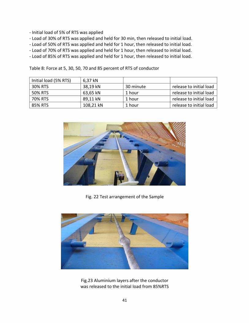
4.2.3.2 TEST METHOD AND PARAMETERS
The test was performed according to the requirements of Clause 6.4.9-6.4.8 and Annex A of the EN 50540 standard. The ends of the specimen were sealed with cold hardening resin and fixed in the end fittings. The conductor was pre-stressed before the stress-strain test. A constant mechanical tension of 53,34 kN was applied to the conductor. First hour strain (ε1 expressed in mm) was compared with second hour strain (ε2 in mm). The ε2/ ε1 was lower than 5% and pre-stress was stopped. Loading conditions for stress-strain test for conductor were applied as follows:
41
- Initial load of 5% of RTS was applied - Load of 30% of RTS was applied and held for 30 min, then released to initial load. - Load of 50% of RTS was applied and held for 1 hour, then released to initial load. - Load of 70% of RTS was applied and held for 1 hour, then released to initial load. - Load of 85% of RTS was applied and held for 1 hour, then released to initial load. Table 8: Force at 5, 30, 50, 70 and 85 percent of RTS of conductor
Initial load (5% RTS) 6,37 kN
30% RTS 38,19 kN 30 minute release to initial load
50% RTS 63,65 kN 1 hour release to initial load
70% RTS 89,11 kN 1 hour release to initial load
85% RTS 108,21 kN 1 hour release to initial load
Fig. 22 Test arrangement of the Sample
Fig.23 Aluminium layers after the conductor was released to the initial load from 85%RTS

42
During the test, the elongation and force was continuously recorded. Figure 24 shows the
measured stress-strain curve of the conductor.
Table 10: The calculated E-modulus values
E (kN/mm2)
E1 E2 E3 E4
425-AL0/55-MUHST conductor 62,08 63,54 65,11 65,57
Fig. 24 Force-elongation curve of the conductor

43
Fig.25 Force Elongation Curve of the Steel Core
Fig. 27 Stress-Strain Curve for whole ACSS Conductor

44
4.2.3.3 BIRD CAGING EFFECT OF ACSS CONDUCTOR
During the stress-strain testing of the conductor, the fully annealed aluminum experience elastic
deformation while the core experience plastic elongation. When the contact force remains
positive, no separation occurs. If, however, the contact force becomes negative somewhere
along the conductor, the outer strands will separate from the core strand. When this separation
strains the conductor material beyond its elastic limit, instability or bird‐caging occurs in the form
of a permanent deformation.
Fig. 28 Bird Caging effect of ACSS Conductor
4.2.4 INVAR CORE CONDUCTORS
These conductors use a special steel alloy Fe-Ni (Invar) which main characteristic is the very low
thermal expansion coefficient. Invar is covered by a thin layer of aluminum extruded on it which
prevent the corrosion and the wire is identified by the acronym ACI (Aluminum Clad Invar). The
conductive external layers are made of a super thermal resistant Al-Zr alloy which operating
temperature can reach the 210°C.
The main advantage of this conductor are :
• Low coefficient of thermal expansion which limit the increasing of temperature with
high temperature,
• Mechanical properties very similar to ACSR,
• High corrosion resistance of core.
45
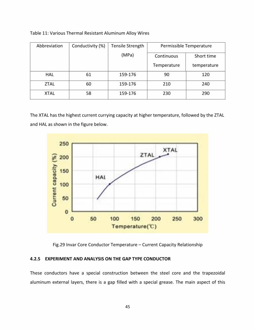
Table 11: Various Thermal Resistant Aluminum Alloy Wires
Abbreviation Conductivity (%)
Tensile Strength
(MPa)
Permissible Temperature
Continuous
Temperature
Short time
temperature
HAL 61 159-176 90 120
ZTAL 60 159-176 210 240
XTAL 58 159-176 230 290
The XTAL has the highest current currying capacity at higher temperature, followed by the ZTAL
and HAL as shown in the figure below.
Fig.29 Invar Core Conductor Temperature – Current Capacity Relationship
4.2.5 EXPERIMENT AND ANALYSIS ON THE GAP TYPE CONDUCTOR
These conductors have a special construction between the steel core and the trapezoidal
aluminum external layers, there is a gap filled with a special grease. The main aspect of this

46
conductor is the possibility to slide between the external layers and the core. Steel and aluminum
are independent, so the external layer may rest on the steel core at high temperatures.
The external conductive layers are made of a super thermal resistant Al- Zr alloy which operating
temperature can reach 210oC.
A similar test protocol was carried out on the gap type conductor (GAPTAl) to calculate both the
tensile strength of the inner steel core and the external aluminum wires. The mass of the grease
was 4.45kg.
The result of the test is shown in the table below:
Table 12: Results of the Gap type conductor
Steel Core Aluminum Layers
Trapezoidal shaped Round shaped
Diameter
(mm)
Force
(N)
Diameter(mm) Force(N) Diameter
(mm)
Force(KN) Specific
Resistivity(Ώmm2/m)
4.47 9900 1.00 1520 4.44 15.570 0.028373
4.47 10000 1.00 1520 4.414 15.613 0.028378
4.48 9900 1.47 1540 4.416 15.457 0.028642
4.47 10000 1.46 1520 4.440 15.480 0.028450
4.47 10100 3.46 1540 4.448 15.537 0.028440
4.48 10000 1.00 1510 4.444 15.513 0.028507
4.48 10000 2.46 1540 4.436 15.454 0.028613

47
The average diameter of the steel core was 4.47mm and the average force was 9985.71N. The
tensile strength = Force/Area was calculated to be 635.02N/mm2. Also the average of the
aluminum layers’ (Trapezoidal shaped) diameter was 1.69mm and the average force was
1527.14N. The calculated tensile strength of the external layers was found to be 628.12N/mm2
and that of the round shaped was 4.43mm, 15.52KN, and 251.21N/mm2.
The average specific resistivity of the conductor was 0.028486Ώmm2/m.
4.3 HIGH TEMPERATURE LOW SAG TEST AND ANALYSIS
The impact of large ice loads, strand settling, or creep, conductor length changes would primarily
be a function of the Coefficient of Thermal Expansion (CTE) of the conductor’s core and aluminum
strands. Conductor temperatures range from the location coldest ambient temperature to the
conductor’s maximum operating temperature.
In non-homogeneous conductor designs, the core material has two purposes for being part of
the conductor. First, it is there to increase overall conductor strength. Second, it is there to lower
the CTE of the overall conductor by offering a CTE much lower than the unavoidable high CTE of
aluminum.
A high temperature test was performed on a 30m by length conductor samples in Fux Zrt indoor
laboratory. The purpose of the measurement was to compare the behavior of HTLS conductors
to conventional ACSR conductors at high temperature to find out the sag-temperature
relationship between them.
Below is the experimental set-up for the test and all the other conductors followed the same set
up protocols.

48
Fig. 30 Set-Up for the HTLS Test
Table 13: Main Characteristics of the Examined conductors
Property 250 AL1/40-ST1A ACCC 290/30
Structure 7x2,8+26x3,45 CC+9x3,9+12xTW(4,5)
Diameter 22.4mm 22.3mm
Weight 1028kg/km 887kg/km
DC Resistivity 0.115 Ω/km 0.0947 Ω/km
Rated Current Carrying
Capacity
760 A 1480A
Each conductor was terminated using epoxy-resin dead ends to ensure that all constituent
components of the conductor would be tensioned. The dead ends comprised a U-bolt and a
housing with a cone shaped cavity. The individual wires of the conductor were splayed out in the
housing and then encapsulated in epoxy. This technique of termination also minimized any slack
Power supply
30m ACSS Conductor
Clamps

49
being introduced into the span. The conductors were reconstituted on the untensioned side of
the epoxy-resin dead ends and fitted with compression terminals at each end.
Fig. 31 Arrangement of ACSR and ACCC for HTLS Test
The conductors were heated using AC current transformer connected in series at the North end
of the span. Approximately 1600 amps was supplied by the current transformers. An electrical
jumper cable was used to connect the ACCC/TW conductor to the ACSR conductor at the South
end of the span. The full available current was cycled on to increase the temperature in the
conductors.
The conductors were tensioned to 25% of their respective rated tensile strengths (RTS). Current
was circulated through both conductors to increase the temperature to the target temperature.
The intent was to increase the temperature of both conductors to approximately 160oC and
measure their respective sags during the heat up.
ACCC
ACSR

50
Table 14: Temperature - sag values of ACSR and ACCC Conductor
250-AL1/40-ST1A ACCC 290/30
Temperature [oC] Sag[m] Temperature[oC] Sag[m]
20 0.09 20 0.09
60 0.34 60 0.25
80 0.42 80 0.26
110 0.52 110 0.26
150 0.64 150 0.27
160 0.67 160 0.28
The temperature plotted against the sag values for the respective conductors in the subsequent
graphs as show below.
Fig. 32 Comparison of the sag value of an ACCC and ACSR conductor.

51
Fig.33 Sag- Temperature Curve of ACSS Conductor
Fig.34 Comparison of Sag –Temperature Relationship of ACSR and Invar Core
0
5
10
15
20
25
0 20 40 60 80 100 120 140 160 180
Sag
[mm
]
Temperature [C°]
Sag - Temperature of ACSS Conductor
Temperature oC
Sag
[mm]

52
4.6.1 THERMAL KNEE POINT TEMPERATURE
As a conductor is subjected to various electrical loads that cause the conductor to heat up, the
dissimilar coefficients of thermal expansion of the core strands and conductive strands cause a
change in tensile load sharing. The aluminum strands expand at a higher rate than the core as
temperature rises which relaxes the aluminum strands and shifts the tensile load to the core. At
some temperature, the tensile stress in the aluminum is overtaken by thermal expansion of the
aluminum, and all tensile load is transferred to the core, leading to no tensile load in the
aluminum strands. The apex of this transition is called the thermal knee point.
Fig. 35 Thermal Knee Point of Invar 240/40 Conductor
In this particular test, which was carried out at Fux company by using a 40m length Invar core
conductor and passing a current of 1600 amps through it, the thermal knee point of the 40m
Invar core conductor was observed at a temperature of 110oC. Knee-point values can vary as a
Sag
(m)
Temperature (oC)

53
function of conductor type, tension, span length and conductor age as ice, cold weather, and
wind loads (high tension conditions) can stretch the aluminum strands, which allows them to
subsequently relax (reduce stress) and shift load to the conductor’s core (reducing the thermal
knee point to at or below the stringing in temperature).
SUMMARY
When the electric energy demand suddenly increases one possibility to replace the conductors
is by the use of HTLS conductors. The common feature of this conductors, is that the maximal
operating temperature is higher than a conventional ACSR conductor, the sag value remains low
at higher temperatures and contains special materials and design which help to achieved that.
ACSR contains stranded steel core and stranded cold drawn aluminum wires. In this type the
strength of the aluminum wires plays a significant role in the strength and mechanical behavior
of the whole conductor. Long term operation over the maximal operating temperature will cause
the conductor to lose their strength. In the case of the HTLS, the core of the conductor plays a
significant role it strength and the stranded aluminum wires play the role of conducting so the
issue of sagging is a not a problem this case.
The construction of the various types of the conductors greatly affect the performance and
purposes for the transmission system. ACSR conductor is a non-homogenous conductor
consisting of a steel core and a stranded cold drawn 1350 aluminum wire with H19 temper
aluminum wires. They have maximum operating temperature of 90oC. ACSS comprises of heat
treated fully annealed aluminum that has a trapezoidal shape. Core of the conductor is made of
extra high strength steel (EHS). This conductor can be operated at 250°C without compromising
its tensile strength. The ZTACIR Shape is more similar to ACSR/AW, the outer strands of Invar
conductor is made of heat treated annealed aluminum strands which can operate at elevated
temperatures. The core of the conductor is made of Aluminum Clad High strength steel which
has a lower thermal expansion value. It has a maximum operation temperature of 210°C. ACCC

54
conductor has a carbon fibre composite core and it outer layer is fully annealed trapezoidal
aluminum wires. ACCC conductors can safely be operated up to 180°C. The Gap type is made up
of Zirconium doped hard drawn aluminum alloy. Outer most layer strands are circular in shape
and the strands in one layer below are trapezoidal in shape. Annular gap is filled with thermal
resistant grease. Inner core is made of High strength steel, Steel core and aluminum core can
move independently to each other due to the presence of grease.
Comparison of the conductors were made based on the various conducted experiments in the
thesis, ACSR conductors have the highest weight ratio as a result of their core (steel), ACCC has
the lowest weight ratio, because it core is made up of carbon fibre which is very light in weight.
There was a clear sag difference between the ACSR and the HTLS conductors. The ACCC
conductors have a small sagging effect as a result of the carbon fibre and it can operate
continuously up to a temperature of 180oC, the resistivity of these conductor was best as result
of the fully annealed cold drawn trapezoidal shaped wires. The ACSS and the invar core were
having an operating tempering temperature of 210 and 250oC respectively as a result of the
annealed or thermal resistant aluminum wires. In the case of ACSS the resistivity was better as
compared to the ACSR because they also have an annealed aluminum wires as their outer layers.
The RTS of the ACSR and ACSS were better because of the steel core but in the case of the ACCC
and the GAP, the strength of the conductors depends on their core.
In the case of reconductoring to increase the current carrying capacity of the transmission lines
immediately, HTLS is the best solution since they can carry large amount of current because of
their low sag effect and higher operating temperature and they can be used without building new
transmission systems. The special materials used in their formation makes these conductors
expensive but if reconductoring is enough to increase the current carrying capacity then the
overall cost involved by using HTLS will be cheaper.

55
References
[1]. Public Service Commission of Wisconsin, “Electric Transmission Lines”, 2012.
[2]. A. F. Cordova, “Electrical Transmission and Distribution Reference Book of Westinghouse”
June 2013.
[3]. B. Edvard, “HV Transmission Line Component”, Technical Articles 2018.
[4]. A. Laurie, “Transmission Basics Facilities, Interconnection and Permitting”, February 2012.
[5]. F.R. Thrash, “Transmission Conductors- A Review of the Design and Selection Criteria”, 2007.
[6]. R. Gorur, B. Mobasher, R. Olsen, “Characterization of Composite Cores for High Temperature Low Sag (HTLS) Conductors”, PSERC Publication, Pages 24-40, July 2009. [7]. T. Varney, “ACSR Graphic Method for Sag-Tension Calculations”, 1927. [8]. “Safe Design Tensions with Respect to Aeolian Vibrations- Part II-Damped Single Conductors with Dampers”, Electra Vol 198, October 2001. [9]. A. E. Livingston, Aluminum Alloy Conductors for Overhead Transmission and Distribution Lines, CEA Paper, Canada, March 1965. [10]. C. R. Bayliss, B. Hardy, Transmission and Distribution Electrical Engineering, 3rd edition, 2010. [11]. Electra Article, “Loss in Strength of Overhead Electrical Conductors Caused by Elevated Temperature Operation”, No. 162, pp. 115-117, 1995. [12]. “Conductors for the Uprating of Overhead Lines”, Working Group B2.12 February 2004. [13]. V.T. Morgan, G.K. Geddy, “Temperature Distribution within ACSR Conductors”, CIGRE 22-101, Paris, 1992. [14]. J.R. Harvey, R.E. Larson, “Creep Equations of Conductors for Sag – tension Calculations”, IEEE CP 72 190-2, New York, 1971. [15]. Aluminum association Handbook, 2nd Edition,1981. [16]. https://www.midalcable.com/ [Accessed August 2018].

56
[17]. A. J. Mazón et al, “Gap - type Conductors: Influence of high temperature in the Compression Clamp Systems," IEEE Bologna Power tech-conference, Bologna, Italy, 2003. [18]. "J Power Systems, “Available: http://www.jpowers.co.jp/english/product/. [Accessed 31 March 2015]. [19]. “Concentric lay stranded overhead electrical conductors containing one or mare gap", 1st edition, IEC, IEC 62420 ,2008. [20]. "CTC Cable Corporation," Available: http://www.ctcglobal.com/. [Accessed 31 March 2015]. [21]. C. Gianfranco, M. Handel and D. Angeli, New types of conductors for overhead lines with high thermal resistance, 2008. [22]. “Thermal Resistance Aluminum Alloy wire for overhead line conductors”, 1st Edition, IEC 62004, 2007. [23]. ASTM B857-95, “Standard specification for Shaped Wire Compact Concentric –Lay-Stranded Aluminum Conductors” Coated Steel Supported, 2012. [24]. H.W. Adam, “Steel Supported Aluminum Conductors for Overhead Transmission Lines,” IEEE Paper T 74054-3, Presented at the IEEE PES Winter Power Meeting, 1974. [25]. CTC-Global, “Engineering Transmission Lines with High Capacity Low Sag ACCC conductors”, 1st Edition, 2012. [26]. C. R. Bayliss, B. Hardy, Transmission and Distribution Electrical Engineering, 3rd Edition, 2011. [27]. IEC, IEC 60104 – “Aluminum-Magnesium-Silicone Alloy Wire for Overhead Line Conductors”, 2nd Edition, 1987-12. [28]. “Zinc Coated Steel Wires for stranded conductors”, 1st Edition, IEC- IEC 60888, 1987. [29]. IEC, “Hard Drawn Aluminum wire for overhead conductors”, 1st Edition, IEC 60889, 1987. [30]. CEB, “CEB Technical Specifications - Employer’s Requirements - Part B of Bidding Document”, Vol. 5 of 8. [31]. IEEE Standard 738, "IEEE Standard for Calculating the Current- Temperature Relationship of Bare Overhead Conductors”, 2006. [32]. IEC, “Overhead Electrical Conductors- Calculation Methods for Stranded Bare Conductors”, 1st Edition, IEC 61597, 1995-05.


