Unplugged: A solar powered audio amplifier with DSP effects Hugo Castellanos, Gretchen Rivera, Sandra Munoz School of Electrical Engineering and Computer Science, University of Central Florida, Orlando, Florida, 32816-2450 Abstract — This paper presents the implementation of a solar powered portable audio amplifier as well as the design approach taken to implement its audio, power management and monitoring subsystems. The ultimate function of this device is to provide individuals with a reliable and easy to use audio amplifier that does not require mains power. The totality of the system runs off a battery with a built-in solar charger. It is capable of taking the input from an MP3 player and a music instrument or microphone and delivering 45 Watts into a 2 ohm load. The system also features a DSP effects unit that enhances its functionality and lets musicians use it to perform music outdoors. Index Terms — Audio systems, Battery management systems, Music, Solar energy, Monitoring I. INTRODUCTION Musicians and music enthusiasts are always looking for new ways of sharing their craft with other people. Sound recording technologies such as magnetic tape and compact discs allowed them to deliver their recorded performances to wider audiences. Still, live music performances are an irreplaceable part of a musician’s life. Musicians that use electrical instruments such as keyboards and electric guitars are at a disadvantage with respect to their acoustic counterparts since they depend in having electronic amplifiers and being attached on the power grid to play. A solar powered amplifier would give them more freedom to play anywhere they wanted too without being tied to the regular power grid. Possible uses of this device could be as personal amplifiers for street performers, music system for outdoor parties or a public address system for small campsites or any other kind of public event where connecting to the power grid is difficult or impossible. This is the main goal of the Unplugged sound system. The motivation to take on this enterprise comes from the personal desire of team members to be able to play musical instruments or just enjoy music from a laptop computer or iPod without the need of running long and cumbersome extension cords. The design for the Unplugged sound system includes one input for either a low impedance microphone, or a musical instrument such as electro-acoustic guitars and an 1/8 inch connector capable of interfacing a laptop computer or MP3 player. The system’s versatility is further enhanced with the inclusion of the BTSE-16FX DSP effects module. This module will let the user implement one of sixteen different audio effects in the audio source of their choice. At the core of this design is the TDA7396 amplifier chip which is capable of delivering a power output of 45 Watts RMS into a 4 Ω speaker. The whole system is powered by a 12 Volt 5 ah SLA battery that is trickle charged by a 20 Watt photovoltaic cell. II. POWER SUBSYSTEM A. Solar Panel For this research solar panels are going to be used to power the whole system. To choose the right solar panel, many things have to be taken in consideration. First, all the current requirements for all the components and parts of the system need to be calculated. For the microcontroller a current of 500uA is required to power it, whereas for the DSP effects 100mA are needed. Also, the LCD display is going to use 300uA. Adding all currents and assuming some leakage occurs gives a total current of around .5A. The type of material of solar cells is a very important characteristic of solar panels. By taking in consideration that a 12V rechargeable battery is going to be used as backup to power the system without the need of plugging it, a 12V, 20 watts solar panel is chosen as the main source of energy as it is shown in fig 1. Fig 1. Monocrystalline Solar Panel.
Transcript
Unplugged: A solar powered audio amplifier with DSP
effects Hugo Castellanos, Gretchen Rivera, Sandra
Munoz
School of Electrical Engineering and Computer Science, University of Central Florida, Orlando,
Florida, 32816-2450
Abstract — This paper presents the implementation of a
solar powered portable audio amplifier as well as the design approach taken to implement its audio, power management and monitoring subsystems. The ultimate function of this device is to provide individuals with a reliable and easy to use audio amplifier that does not require mains power. The totality of the system runs off a battery with a built-in solar charger. It is capable of taking the input from an MP3 player and a music instrument or microphone and delivering 45 Watts into a 2 ohm load. The system also features a DSP effects unit that enhances its functionality and lets musicians use it to perform music outdoors.
Index Terms — Audio systems, Battery management systems, Music, Solar energy, Monitoring
I. INTRODUCTION
Musicians and music enthusiasts are always looking for new ways of sharing their craft with other people. Sound recording technologies such as magnetic tape and compact discs allowed them to deliver their recorded performances to wider audiences. Still, live music performances are an irreplaceable part of a musician’s life. Musicians that use electrical instruments such as keyboards and electric guitars are at a disadvantage with respect to their acoustic counterparts since they depend in having electronic amplifiers and being attached on the power grid to play. A solar powered amplifier would give them more freedom to play anywhere they wanted too without being tied to the regular power grid. Possible uses of this device could be as personal amplifiers for street performers, music system for outdoor parties or a public address system for small campsites or any other kind of public event where
connecting to the power grid is difficult or impossible. This is the main goal of the Unplugged sound system.
The motivation to take on this enterprise comes from
the personal desire of team members to be able to play musical instruments or just enjoy music from a laptop computer or iPod without the need of running long and cumbersome extension cords. The design for the Unplugged sound system includes one input for either a low impedance microphone, or a musical instrument such as electro-acoustic guitars and an 1/8 inch connector capable of interfacing a laptop computer or MP3 player. The system’s versatility is further enhanced with the inclusion of the BTSE-16FX DSP effects module. This module will let the user implement one of sixteen different audio effects in the audio source of their choice. At the core of this design is the TDA7396 amplifier chip which is capable of delivering a power output of 45 Watts RMS into a 4 Ω speaker. The whole system is powered by a 12 Volt 5 ah SLA battery that is trickle charged by a 20 Watt photovoltaic cell.
II. POWER SUBSYSTEM
A. Solar Panel
For this research solar panels are going to be used to power the whole system. To choose the right solar panel, many things have to be taken in consideration. First, all the current requirements for all the components and parts of the system need to be calculated. For the microcontroller a current of 500uA is required to power it, whereas for the DSP effects 100mA are needed. Also, the LCD display is going to use 300uA. Adding all currents and assuming some leakage occurs gives a total current of around .5A.
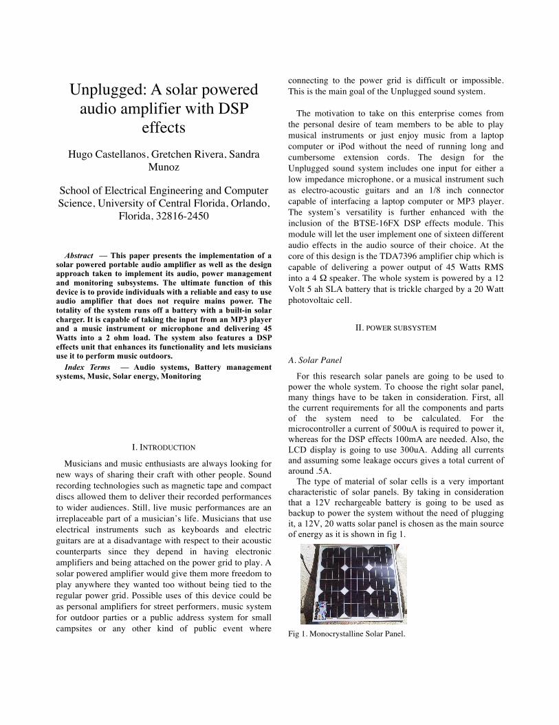
The type of material of solar cells is a very important characteristic of solar panels. By taking in consideration that a 12V rechargeable battery is going to be used as backup to power the system without the need of plugging it, a 12V, 20 watts solar panel is chosen as the main source of energy as it is shown in fig 1. Fig 1. Monocrystalline Solar Panel.
€
Rsense = .1 Ichg(MAX )
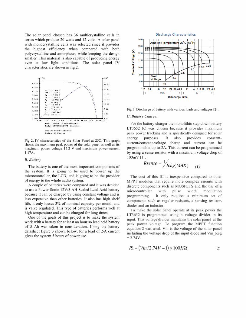
The solar panel chosen has 36 multicrystalline cells in series which produce 20 watts and 12 volts. A solar panel with monocrystalline cells was selected since it provides the highest efficiency when compared with both polycrystalline and amorphous, while keeping the design smaller. This material is also capable of producing energy even at low light conditions. The solar panel IV characteristics are shown in fig 2.
Fig 2. IV characteristics of the Solar Panel at 25C. This graph shows the maximum peak power of the solar panel as well as its maximum power voltage 17.2 V and maximum power current 1.17A.
B. Battery
The battery is one of the most important components of the system. It is going to be used to power up the microcontroller, the LCD, and is going to be the provider of energy to the whole audio system.
A couple of batteries were compared and it was decided to use a Power-Sonic 12V/5 AH Sealed Lead Acid battery because it can be charged by using constant voltage and is less expensive than other batteries. It also has high shelf life, it only losses 3% of nominal capacity per month and is valve regulated. This type of batteries performs well at high temperature and can be charged for long times.
One of the goals of this project is to make the system work with a battery for at least an hour so lead acid battery of 5 Ah was taken in consideration. Using the battery datasheet figure 3 shown below, for a load of .5A current gives the system 5 hours of power use.
Fig 3. Discharge of battery with various loads and voltages [2].
C. Battery Charger
For the battery charger the monolithic step down battery LT3652 IC was chosen because it provides maximum peak power tracking and is specifically designed for solar energy purposes. It also provides constant-current/constant-voltage charge and current can be programmable up to 2A. This current can be programmed by using a sense resistor with a maximum voltage drop of 100mV [1].
(1)
The cost of this IC is inexpensive compared to other MPPT modules that require more complex circuits with discrete components such as MOSFETS and the use of a microcontroller with pulse width modulation programming. It only requires a minimum set of components such as regular resistors, a sensing resistor, diodes and an inductor.
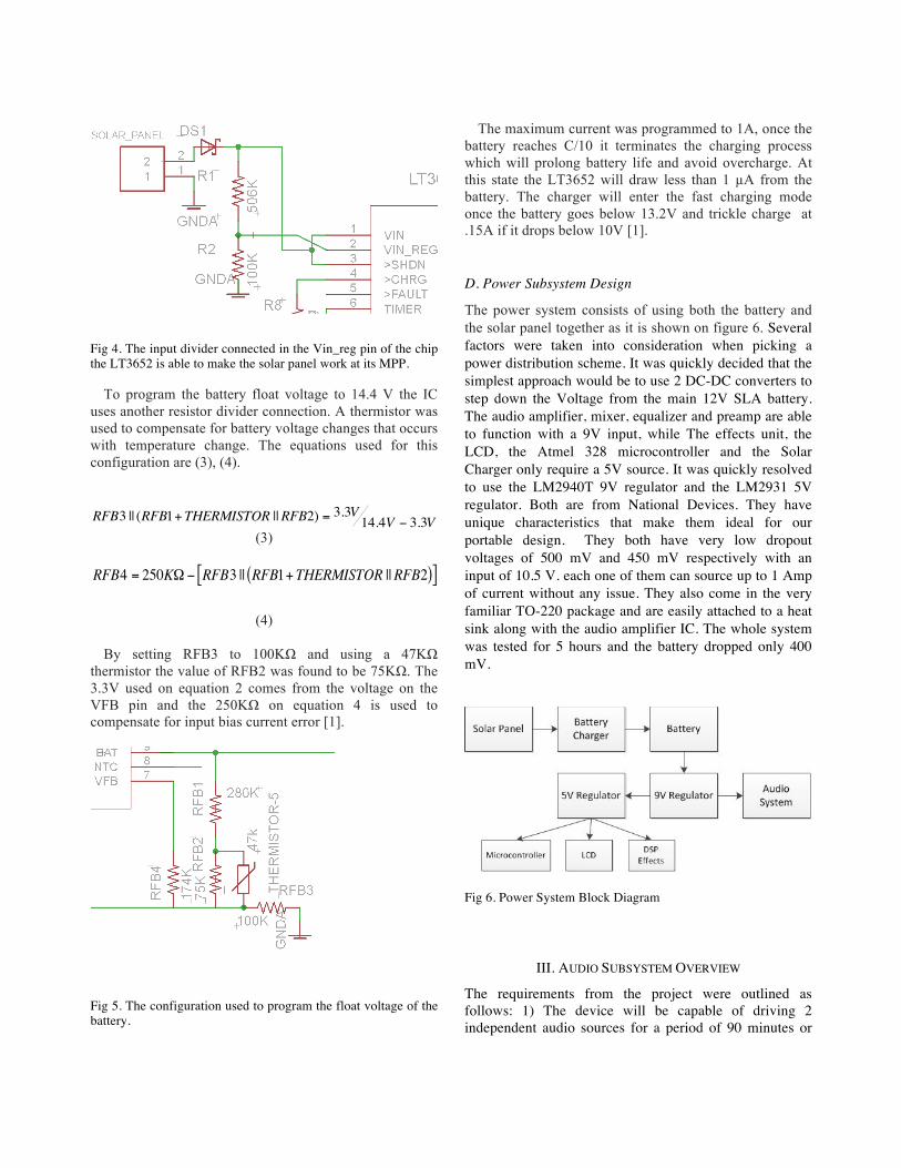
To make the solar panel operate at its peak power the LT3652 is programmed using a voltage divider in its input. This voltage divider maintains the solar panel at the peak power voltage. To program the MPPT function equation 2 was used. Vin is the voltage of the solar panel including the voltage drop of the input diode and Vin_Reg = 2.74V.
€
R1 = Vin /2.74V −1( ) ×100KΩ (2)
Fig 4. The input divider connected in the Vin_reg pin of the chip the LT3652 is able to make the solar panel work at its MPP.
To program the battery float voltage to 14.4 V the IC uses another resistor divider connection. A thermistor was used to compensate for battery voltage changes that occurs with temperature change. The equations used for this configuration are (3), (4).
By setting RFB3 to 100KΩ and using a 47KΩ thermistor the value of RFB2 was found to be 75KΩ. The 3.3V used on equation 2 comes from the voltage on the VFB pin and the 250KΩ on equation 4 is used to compensate for input bias current error [1].
Fig 5. The configuration used to program the float voltage of the battery.
The maximum current was programmed to 1A, once the battery reaches C/10 it terminates the charging process which will prolong battery life and avoid overcharge. At this state the LT3652 will draw less than 1 µA from the battery. The charger will enter the fast charging mode once the battery goes below 13.2V and trickle charge at .15A if it drops below 10V [1].
D. Power Subsystem Design
The power system consists of using both the battery and the solar panel together as it is shown on figure 6. Several factors were taken into consideration when picking a power distribution scheme. It was quickly decided that the simplest approach would be to use 2 DC-DC converters to step down the Voltage from the main 12V SLA battery. The audio amplifier, mixer, equalizer and preamp are able to function with a 9V input, while The effects unit, the LCD, the Atmel 328 microcontroller and the Solar Charger only require a 5V source. It was quickly resolved to use the LM2940T 9V regulator and the LM2931 5V regulator. Both are from National Devices. They have unique characteristics that make them ideal for our portable design. They both have very low dropout voltages of 500 mV and 450 mV respectively with an input of 10.5 V. each one of them can source up to 1 Amp of current without any issue. They also come in the very familiar TO-220 package and are easily attached to a heat sink along with the audio amplifier IC. The whole system was tested for 5 hours and the battery dropped only 400 mV.
Fig 6. Power System Block Diagram
III. AUDIO SUBSYSTEM OVERVIEW
The requirements from the project were outlined as follows: 1) The device will be capable of driving 2 independent audio sources for a period of 90 minutes or
more. 2) The device will be capable of driving signals from a portable MP3 player and a line level input suitable for a guitar or a microphone. 3) The device will be able to interface professional audio connectors such as the 3.5 mm stereo for portable MP3 players and the ¼ inch TRS for music instruments and microphones. 4) The line level audio input will be equipped with a tone control circuit with a dynamic range of +/- 10 dB to compensate for any acoustical inadequacies of the environment where the sound system is used. 5) The instrument input channel will allow the user to blend the instrument input audio with the effects unit from 0dB to 10dB. 6) Each individual analog input must posses a dedicated volume control.
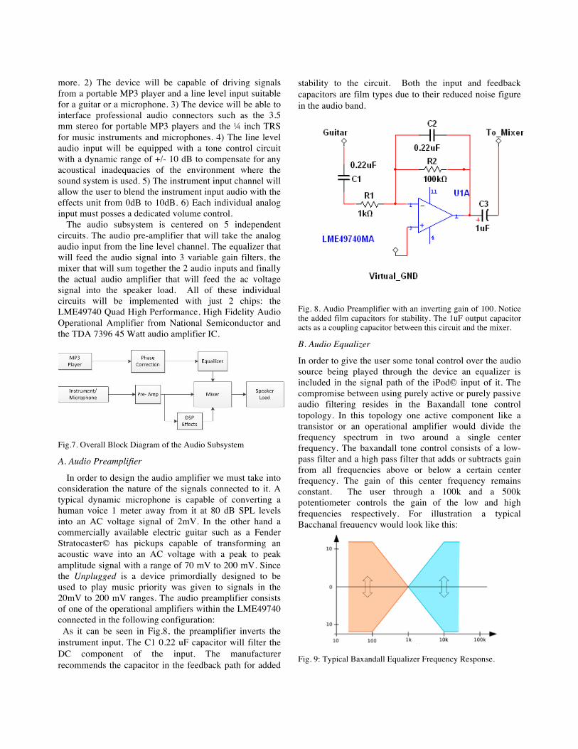
The audio subsystem is centered on 5 independent circuits. The audio pre-amplifier that will take the analog audio input from the line level channel. The equalizer that will feed the audio signal into 3 variable gain filters, the mixer that will sum together the 2 audio inputs and finally the actual audio amplifier that will feed the ac voltage signal into the speaker load. All of these individual circuits will be implemented with just 2 chips: the LME49740 Quad High Performance, High Fidelity Audio Operational Amplifier from National Semiconductor and the TDA 7396 45 Watt audio amplifier IC.
Fig.7. Overall Block Diagram of the Audio Subsystem
stability to the circuit. Both the input and feedback capacitors are film types due to their reduced noise figure in the audio band.
Fig. 8. Audio Preamplifier with an inverting gain of 100. Notice the added film capacitors for stability. The 1uF output capacitor acts as a coupling capacitor between this circuit and the mixer.
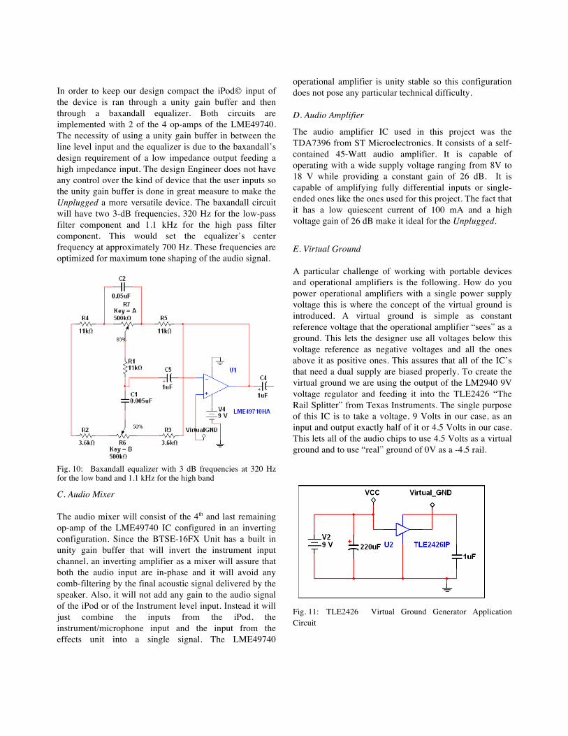
Fig. 10: Baxandall equalizer with 3 dB frequencies at 320 Hz for the low band and 1.1 kHz for the high band
C. Audio Mixer
The audio mixer will consist of the 4th and last remaining op-amp of the LME49740 IC configured in an inverting configuration. Since the BTSE-16FX Unit has a built in unity gain buffer that will invert the instrument input channel, an inverting amplifier as a mixer will assure that both the audio input are in-phase and it will avoid any comb-filtering by the final acoustic signal delivered by the speaker. Also, it will not add any gain to the audio signal of the iPod or of the Instrument level input. Instead it will just combine the inputs from the iPod, the instrument/microphone input and the input from the effects unit into a single signal. The LME49740
operational amplifier is unity stable so this configuration does not pose any particular technical difficulty.
D. Audio Amplifier
The audio amplifier IC used in this project was the TDA7396 from ST Microelectronics. It consists of a self- contained 45-Watt audio amplifier. It is capable of operating with a wide supply voltage ranging from 8V to 18 V while providing a constant gain of 26 dB. It is capable of amplifying fully differential inputs or single-ended ones like the ones used for this project. The fact that it has a low quiescent current of 100 mA and a high voltage gain of 26 dB make it ideal for the Unplugged.
E. Virtual Ground
A particular challenge of working with portable devices and operational amplifiers is the following. How do you power operational amplifiers with a single power supply voltage this is where the concept of the virtual ground is introduced. A virtual ground is simple as constant reference voltage that the operational amplifier “sees” as a ground. This lets the designer use all voltages below this voltage reference as negative voltages and all the ones above it as positive ones. This assures that all of the IC’s that need a dual supply are biased properly. To create the virtual ground we are using the output of the LM2940 9V voltage regulator and feeding it into the TLE2426 “The Rail Splitter” from Texas Instruments. The single purpose of this IC is to take a voltage, 9 Volts in our case, as an input and output exactly half of it or 4.5 Volts in our case. This lets all of the audio chips to use 4.5 Volts as a virtual ground and to use “real” ground of 0V as a -4.5 rail.
The purpose of this subsystem was to create an interface between the user and the internal system by the means of an LCD. With the addition of a microcontroller and an LCD, the user can be constantly informed of the state of the solar panel, the battery and the DSP effects. It was imperative that the project included this subsystem, as it is through it that the user will be able to detect any substantial changes and take action to prevent any damage to the unit.
A. Microcontroller
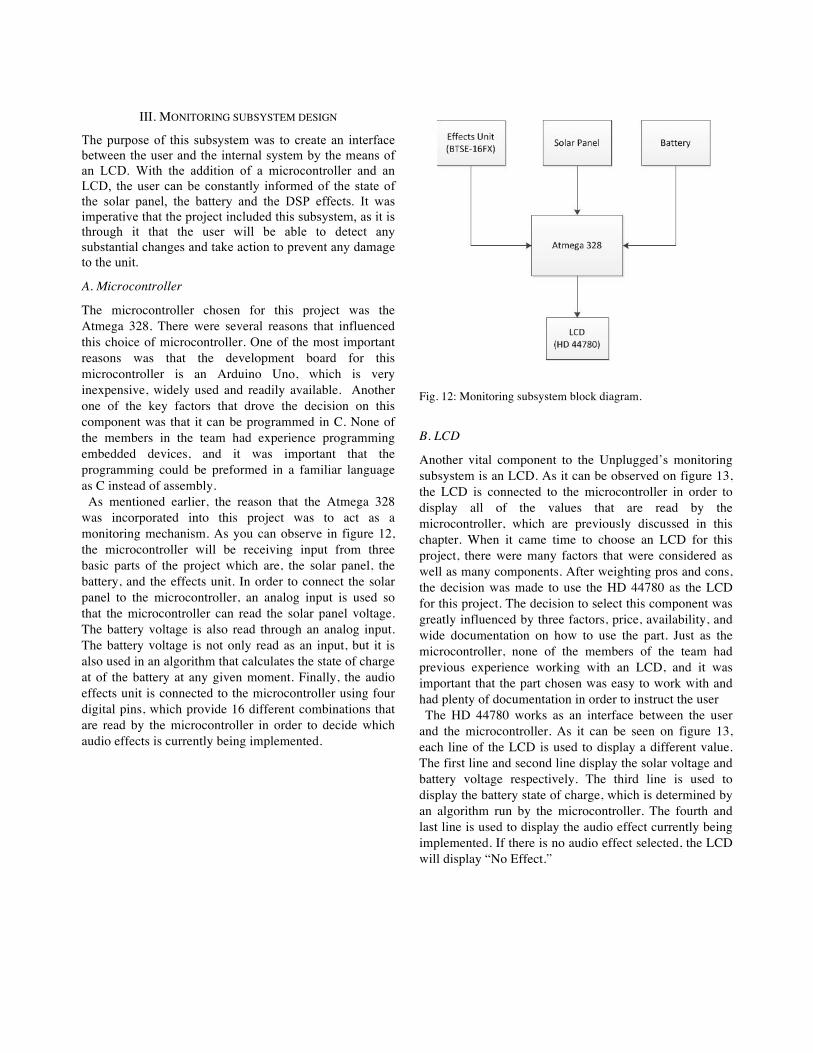
The microcontroller chosen for this project was the Atmega 328. There were several reasons that influenced this choice of microcontroller. One of the most important reasons was that the development board for this microcontroller is an Arduino Uno, which is very inexpensive, widely used and readily available. Another one of the key factors that drove the decision on this component was that it can be programmed in C. None of the members in the team had experience programming embedded devices, and it was important that the programming could be preformed in a familiar language as C instead of assembly. As mentioned earlier, the reason that the Atmega 328 was incorporated into this project was to act as a monitoring mechanism. As you can observe in figure 12, the microcontroller will be receiving input from three basic parts of the project which are, the solar panel, the battery, and the effects unit. In order to connect the solar panel to the microcontroller, an analog input is used so that the microcontroller can read the solar panel voltage. The battery voltage is also read through an analog input. The battery voltage is not only read as an input, but it is also used in an algorithm that calculates the state of charge at of the battery at any given moment. Finally, the audio effects unit is connected to the microcontroller using four digital pins, which provide 16 different combinations that are read by the microcontroller in order to decide which audio effects is currently being implemented.
Fig. 12: Monitoring subsystem block diagram.
B. LCD
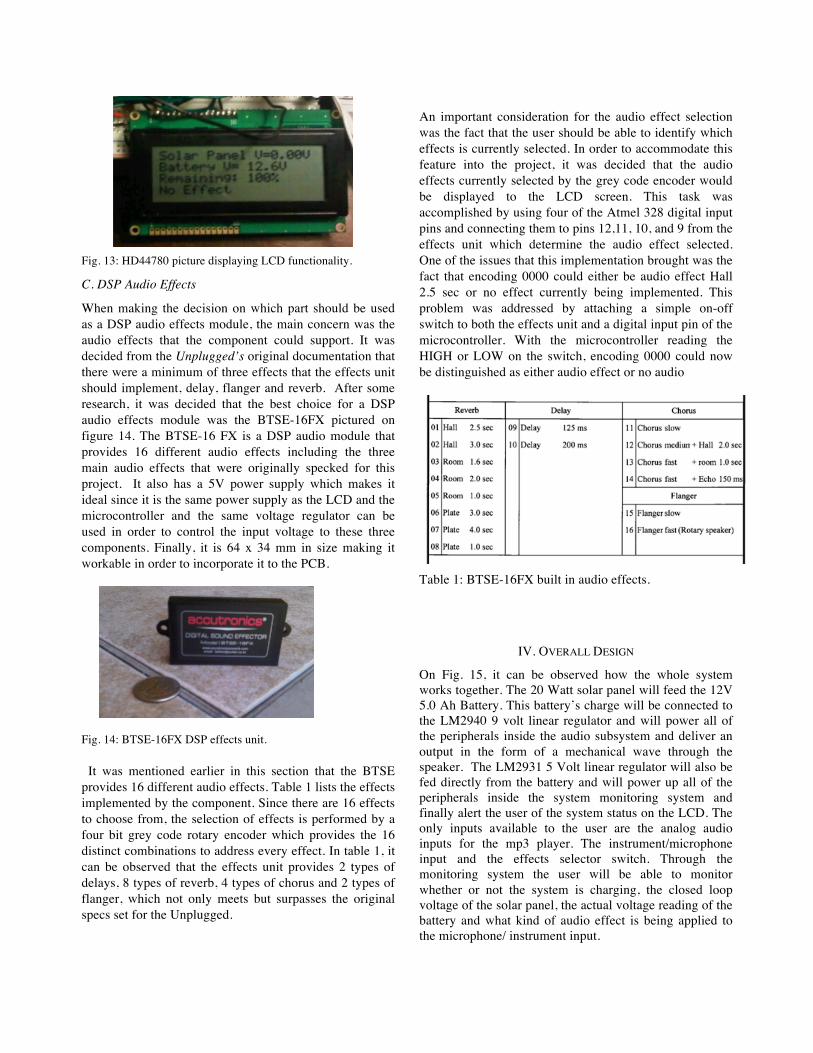
Another vital component to the Unplugged’s monitoring subsystem is an LCD. As it can be observed on figure 13, the LCD is connected to the microcontroller in order to display all of the values that are read by the microcontroller, which are previously discussed in this chapter. When it came time to choose an LCD for this project, there were many factors that were considered as well as many components. After weighting pros and cons, the decision was made to use the HD 44780 as the LCD for this project. The decision to select this component was greatly influenced by three factors, price, availability, and wide documentation on how to use the part. Just as the microcontroller, none of the members of the team had previous experience working with an LCD, and it was important that the part chosen was easy to work with and had plenty of documentation in order to instruct the user The HD 44780 works as an interface between the user and the microcontroller. As it can be seen on figure 13, each line of the LCD is used to display a different value. The first line and second line display the solar voltage and battery voltage respectively. The third line is used to display the battery state of charge, which is determined by an algorithm run by the microcontroller. The fourth and last line is used to display the audio effect currently being implemented. If there is no audio effect selected, the LCD will display “No Effect.”
When making the decision on which part should be used as a DSP audio effects module, the main concern was the audio effects that the component could support. It was decided from the Unplugged’s original documentation that there were a minimum of three effects that the effects unit should implement, delay, flanger and reverb. After some research, it was decided that the best choice for a DSP audio effects module was the BTSE-16FX pictured on figure 14. The BTSE-16 FX is a DSP audio module that provides 16 different audio effects including the three main audio effects that were originally specked for this project. It also has a 5V power supply which makes it ideal since it is the same power supply as the LCD and the microcontroller and the same voltage regulator can be used in order to control the input voltage to these three components. Finally, it is 64 x 34 mm in size making it workable in order to incorporate it to the PCB. Fig. 14: BTSE-16FX DSP effects unit. It was mentioned earlier in this section that the BTSE provides 16 different audio effects. Table 1 lists the effects implemented by the component. Since there are 16 effects to choose from, the selection of effects is performed by a four bit grey code rotary encoder which provides the 16 distinct combinations to address every effect. In table 1, it can be observed that the effects unit provides 2 types of delays, 8 types of reverb, 4 types of chorus and 2 types of flanger, which not only meets but surpasses the original specs set for the Unplugged.
An important consideration for the audio effect selection was the fact that the user should be able to identify which effects is currently selected. In order to accommodate this feature into the project, it was decided that the audio effects currently selected by the grey code encoder would be displayed to the LCD screen. This task was accomplished by using four of the Atmel 328 digital input pins and connecting them to pins 12,11, 10, and 9 from the effects unit which determine the audio effect selected. One of the issues that this implementation brought was the fact that encoding 0000 could either be audio effect Hall 2.5 sec or no effect currently being implemented. This problem was addressed by attaching a simple on-off switch to both the effects unit and a digital input pin of the microcontroller. With the microcontroller reading the HIGH or LOW on the switch, encoding 0000 could now be distinguished as either audio effect or no audio Table 1: BTSE-16FX built in audio effects.
IV. OVERALL DESIGN
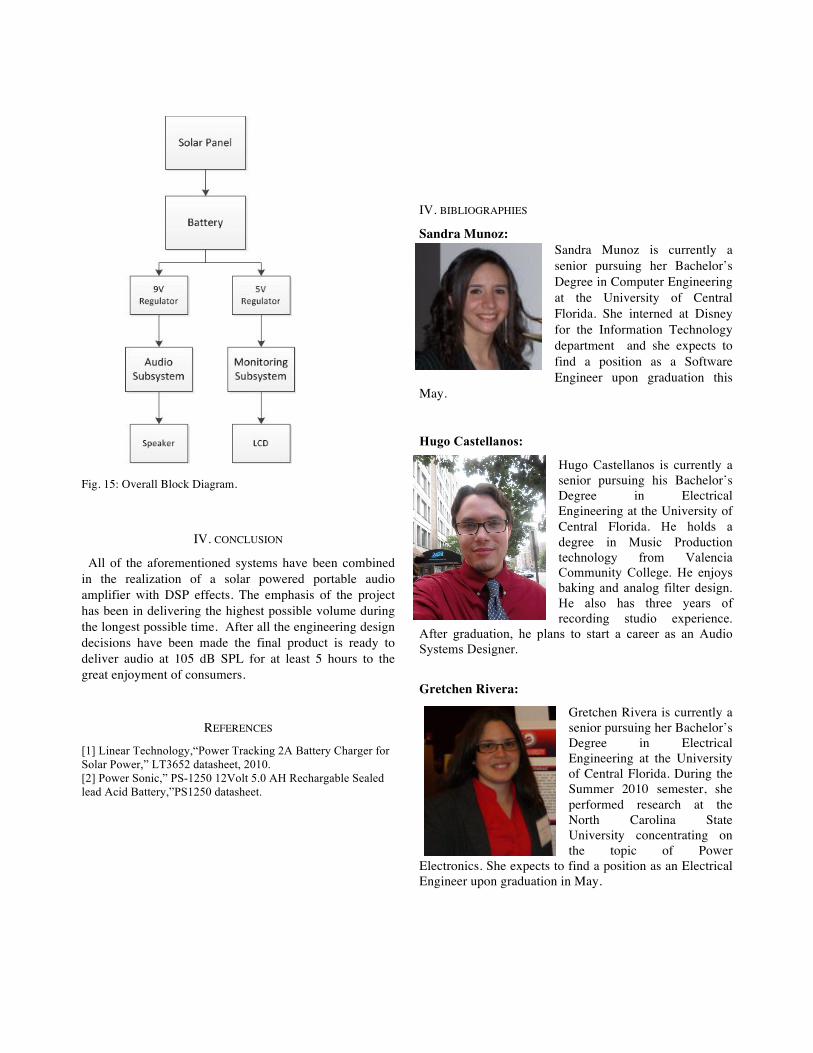
On Fig. 15, it can be observed how the whole system works together. The 20 Watt solar panel will feed the 12V 5.0 Ah Battery. This battery’s charge will be connected to the LM2940 9 volt linear regulator and will power all of the peripherals inside the audio subsystem and deliver an output in the form of a mechanical wave through the speaker. The LM2931 5 Volt linear regulator will also be fed directly from the battery and will power up all of the peripherals inside the system monitoring system and finally alert the user of the system status on the LCD. The only inputs available to the user are the analog audio inputs for the mp3 player. The instrument/microphone input and the effects selector switch. Through the monitoring system the user will be able to monitor whether or not the system is charging, the closed loop voltage of the solar panel, the actual voltage reading of the battery and what kind of audio effect is being applied to the microphone/ instrument input.
Fig. 15: Overall Block Diagram.
IV. CONCLUSION
All of the aforementioned systems have been combined in the realization of a solar powered portable audio amplifier with DSP effects. The emphasis of the project has been in delivering the highest possible volume during the longest possible time. After all the engineering design decisions have been made the final product is ready to deliver audio at 105 dB SPL for at least 5 hours to the great enjoyment of consumers.
REFERENCES
[1] Linear Technology,“Power Tracking 2A Battery Charger for Solar Power,” LT3652 datasheet, 2010. [2] Power Sonic,” PS-1250 12Volt 5.0 AH Rechargable Sealed lead Acid Battery,”PS1250 datasheet.
IV. BIBLIOGRAPHIES
Sandra Munoz: Sandra Munoz is currently a senior pursuing her Bachelor’s Degree in Computer Engineering at the University of Central Florida. She interned at Disney for the Information Technology department and she expects to find a position as a Software Engineer upon graduation this
May. Hugo Castellanos:
Hugo Castellanos is currently a senior pursuing his Bachelor’s Degree in Electrical Engineering at the University of Central Florida. He holds a degree in Music Production technology from Valencia Community College. He enjoys baking and analog filter design. He also has three years of recording studio experience.
After graduation, he plans to start a career as an Audio Systems Designer.
Gretchen Rivera:
Gretchen Rivera is currently a senior pursuing her Bachelor’s Degree in Electrical Engineering at the University of Central Florida. During the Summer 2010 semester, she performed research at the North Carolina State University concentrating on the topic of Power
Electronics. She expects to find a position as an Electrical Engineer upon graduation in May.