116
MOBA-MATIC OPERATOR’S MANUAL Version 4.28-005 (01.2003) MOBA Mobile Automation AG (P/N 499992526007) 23561 (02/05)

MOBA Mobile Automation AG
(P/N 499992526007) 23561 (02/05)
MOBA-MATICOPERATOR’S MANUAL
Version 4.28-005 (01.2003)


MOBA-matic, CAN Operating instructions
-english-
version 4.28-005 and higher

The text and graphics of this manual have been elaborated with the greatest possible care. However, we may not be held liable for possible errors and failure effects. Should you wish to make suggestions regarding the arrangement of this manual or point out possible errors, please contact your local dealer. We will gladly take up any of your ingenious ideas and suggestions.
Some company and label names are subject to label-, patent- or trade-mark protection. All rights reserved. This document must not be duplicated or transferred for any purpose whatsoever without MOBA’s written consent, irrespective of the way or the means which are used.
Order-no.: 10-02-00855 Date: 01.2003
MOBA
Mobile Automation AG Vor den Eichen 4
D-65604 Elz Internet: www.moba.de
3
Table of Contents: 1. General information ....................................................................... 5
1.1 Introduction.............................................................................. 5 1.2 Packaging and storage ................................................................ 6 1.3 Precautionary measures .............................................................. 7 2. Product description .......................................................................10 3. System summary ..........................................................................11
3.1 Mechanical Components .........................................................13 3.2 System Configurations ............................................................15
4. The digital controller .....................................................................18 4.1 Description of the digital controller ..........................................18 4.2 Switch on test .........................................................................22 4.3 Sensor identification ...............................................................22 4.4 Operator menu ........................................................................23 4.4.2 Sensor selection ..................................................................26 4.4.4 Sensitivity setting .................................................................28 4.4.5 Control window setting .........................................................31 4.4.6 Unit of distance setting.........................................................32 4.4.7 Position factor ......................................................................33 4.4.8 Hydraulic record...................................................................36 4.4.9 Graphic representation of the operator menu........................37 4.5 Different user settings .............................................................38
5. The Digi-Slope sensor ..................................................................40 5.1 Description..............................................................................40 5.2 Mounting.................................................................................40 5.3 Operation of the Digi-Slope sensor..........................................41
6.The Sonic-Ski sensor.....................................................................44 6.1 Description..............................................................................44 6.2 Mounting instructions and working range.................................44 6.3 Working with the Sonic-Ski sensor ..........................................46
7. The Rotary sensor ........................................................................50 7.1 Description..............................................................................50 7.2 Mounting instructions and possible applications ......................50 7.3 Working with the Rotary sensor ...............................................53
8. The Wire Rope sensor (YOYO) .....................................................57 8.1 Description..............................................................................57 8.2 Mounting.................................................................................57 8.3 Working with the Wire Rope sensor .........................................59
9. The laser receiver LS 250 .............................................................62 9.1 Description..............................................................................62 9.2 Mounting instructions ..............................................................62 9.3 Working with the laser receiver LS 250 ...................................64
10. The Big-Ski .................................................................................67 10.1 Description............................................................................67 10.4 Set-up ...................................................................................71 10.5 Working with the Big-Ski .......................................................72
11. Maintenance ...............................................................................75 11.1 General information...............................................................75 11.2 How to clean the unit.............................................................75
12. Remedial measures in case of malfunction..................................76

4
12.1 General information .............................................................. 76 12.2 Fault indications and remedial measures .............................. 77
13. Technical data ........................................................................... 78 14. Parameter menu ........................................................................ 88
14.1 General information .............................................................. 88 14.2 Operator menu ..................................................................... 89 14.3 Basic parameter menu.......................................................... 93
15. Controller set up examples....................................................... 106 15.1 Steps to program a controller for a paver ............................ 106 15.2 Steps to progam a controller for a mill ................................ 110
16. Declaration of conformance...................................................... 114

5
1. General information
1.1 Introduction
This manual contains important information concerning the installation, initiation and
operation of the MOBA-matic, as well as tips for maintenance and trouble shooting.
Furthermore, you will find a detailed description of all operating elements and their
functions.
A description of all interfaces and their configuration is enclosed for the purpose of
connection and trouble shooting.
MOBA-matic is available with various sensor combinations. Please always use these
operating instructions when working with your MOBA-matic system.
In case that your MOBA-matic system is not equipped with all sensors, please
disregard the respective descriptions.
Pictograms and symbols: The following pictrograms and symbols are used in this manual:
Residual risks and sources of danger in the event of improper handling
which place the life and limb of operating personnel at risk are marked by
a warning triangle with an exclamation mark. This also applies to potential
damage to equipment..
Notes which need to be observed are indicated by a hand symbol.
Particularly important notes are printed in bold type.
• Lists are marked by a black dot.
Operating steps to be performed by operating personnel are indicated by an
arrow head.
6 Subject to change (without notice): We have taken trouble to keep the information in these operating instructions
correct and up to date. To maintain our technical leadership it may be necessary,
without notice, to make changes to the product or its operation which, in certain
circumstances, do not correspond to these instructions. In this case your MOBA
supplier can supply up to date operating instructions. We accept no liability for
disturbances, breakdowns or damages caused thereby.
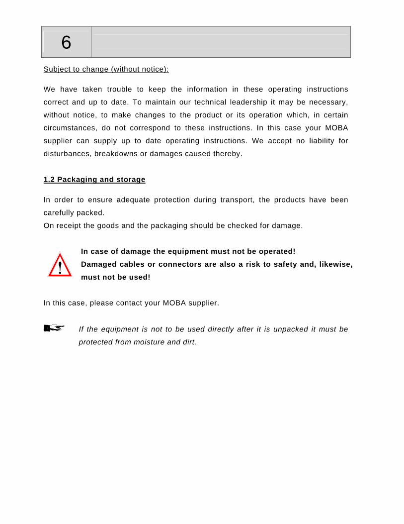
1.2 Packaging and storage
In order to ensure adequate protection during transport, the products have been
carefully packed.
On receipt the goods and the packaging should be checked for damage.
In case of damage the equipment must not be operated! Damaged cables or connectors are also a risk to safety and, likewise, must not be used!
In this case, please contact your MOBA supplier.
If the equipment is not to be used directly after it is unpacked it must be
protected from moisture and dirt.

7
1.3 Precautionary measures
Before mounting, servicing and operating the equipment please read the operating instructions carefully and completely. If questions arise, please contact your MOBA supplier.
Safety measures: The safety measures recommended here correspond basically to the guidelines for
installation and commissioning of electrical systems. They can be used for all
applications in conjunction with MOBA equipment.
Mounting: When mounting the equipment only original MOBA cables may be used. The
connectors may not be removed from the cables because they are protected against
moisture; removing them will damage the protection. Make sure that the all the
screws of the connectors are tight. Additional mounting information for the
equipment and sensors can be obtained from the enclosed data sheets or the
installation instructions.
Wiring: The wiring must be carried out correctly and correspond to the information given in
these instructions. All supply leads and connecting terminals must be sized for the
corresponding current. Further, all connections must be made in accordance with
valid VDE regulations or with valid national regulations.
Safety against disturbances: This equipment has been designed for industrial use and has been tested
accordingly. However, microprocessor technology puts certain demands on the
installation. We would therefore like to point out the following things about an
installation that, if not taken into account, can lead later to disturbances during
operation:

8 • Ensure that the polarity of the connections is correct;
• Supply voltages may not exceed, or fall short of, the specified values;
• Protect the equipment with a suitable supply fuse;
• Use cables suitable for the currents and voltages ;
• Make the cabling paths as short as possible (avoid loops);
• Separate control cables from power cables as far as possible;
• Suppress contactor and relais coils; (diode suppressor connectors)
• The requirement for a disturbance-free operation is a good electrical connection
between the machine and the case/chassis of the separate components;
• Connnect screened cables to earth at one end only (the equipment end);
• Do not supply other equipment directly from the supply terminals of this
equipment;
• Do not use unused terminals as connection points for other equipment;
• Remove all system components, disconnect their power supply before welding;
Maximum Voltages: Do not exceed the maximum allowed voltages. The maximum voltage between any
two isolated circuits, or between one circuit and earth, is, if not otherwise noted,
limited to the highest value of the corresponding input voltage or the corresponding
supply voltage. The connecting terminals or plug must be equipped with a fuse.
Fuses: The equipment is designed with electronic fuses for protection against reversed
connections, voltage spikes and short term over-voltages. The supply voltages given
in the technical data must not be exceeded.
Configuration: The equipment can be configured by the user. When reconfiguring, the user is
obliged to do this only in accordance with the circumstances of the complete
system.

9
Alarm device: In complex systems, in which a malfunction could lead to danger to the operating
personnel or to the system, it is wise to employ an independent alarm device to
supervise the process. An independent device offers protection by announcing an
alarm and switching off the system. In many cases the use of an alarm in the
controller does not, provide adequate protection.
Areas endangered by explosion:
The equipment is not for use in areas endangered by explosion.
Clearance of faults: Before starting to clear faults make sure that every voltage supply to the equipment
has been removed. Faulty equipment should be examined in an area suitably set up
out for test purposes. Every attempt to correct a fault in equipment that is still
installed can be dangerous for personnel and for the system. Before you remove or
exchange sensors in the system, make sure that the supply voltages have been
removed.
Ask for help: For questions about the operation or about mounting please contact your MOBA
supplier.
Failure to observe the above measures can lead to a failure of the equipment, of the machine or even injury to personnel. Damage or injury, which is traceable to non-observance of the precautionary measures described above, is excluded from the manufacturer´s guarantee.

10 2. Product description
The MOBA-matic is a universal control system for building machines of all types.
The extensive range of sensors used for distance- and slope measurement as well
as its ease of operation and reliability make MOBA-matic a flexible and efficient
control system for pavers, concrete road finishers, mastic asphalt finishers, milling
machines, dozers, Kilvar- and built-on graders.
The system is based on modern micro-processor technology and communicates
using the ”CAN-bus“ (Controlled Area Network).
This CAN-bus represents the state of the art in electronic vehicle equipment and
therefore guarantees maximum system safety. Furthermore, it facilitates the
system’s central operation and, due to its modular design, its ability for expansion.
Due to this, you may fit in new sensors anytime and without any problems, so that
the system will always suit the application requirements.
The heart of the system, the digital controller, identifies all connected sensors
automatically as soon as the system is switched on.
In addition to this, MOBA-matic can also be connected to a GPS or total station.

11
3. System summary
COMPONENTS DESCRIPTION PART #
DLS II – V4.28, "Global version"Digital controller with integrated LED indicator, 12pole connector to machine(connecting cables see "equipment")
04-25-10453
Sonic-Ski Sensor, CANMultiple-ultrasonic - Grade sensor 04-21-10020
Dual-Sonic Sensor, CANSingle-ultrasonic sensor with temp. compensation
04-21-10100
Rotary Sensor, CANMechanical Grade Sensor 04-21-40110
Rotary Sensor, CANMechanical Grade Sensor withwand, skate and grid arm
05-21-40110
LS-250 Proportional Laser Receiver 04-60-11010
Wire Rope SensorFor Mill applications 04-21-30020
Slope Sensor, CANSlope sensor with mounting plate 04-21-21010
Electronics

12
COMPONENTS DESCRIPTION PART NUMBERCoil cable, machineto connect CAN-controller or(Power-CAN-Box)/machineBarber Greene/Servo,CAT Servo,Cedarrapids,Champion,Roadtec,Ingersoll Rand,Gilcrest,Neal,ABG,Bitelli,Marini,Voegele,Dynapac,Demag
04-02-02560
Coil cable, machineto connect CAN-controller or(Power-CAN-Box)/machineBarber Greene/CAT Proportional
04-02-02562
Coil cable, machineto connect CAN-controller or(Power-CAN-Box)/machineBlaw Knox Paver
04-02-02563
Coil cable,to connect CAN-controller/sensors/junction box to a hard wired CAN-BUS
04-02-02620
Straight cable, 3 Meter to connect CAN-controller to the slope sensor 04-02-02660
Straight cable, 1 Meterto connect CAN-controller to the slope sensor 04-02-08008
Junctionbox for fixed wiring of CAN-Slope and 3-D
04-03-00420
Junctionbox to connect up to Grade Sensors, CAN 04-03-00415
Cables and Junction Boxes

13
3.1 Mechanical Components

14

15
3.2 System Configurations

16

17

18 4. The digital controller In this section the general operation of the controller is
described. In the operating instructions for the individual
sensors an understanding of the general operation is assumed.
4.1 Description of the digital controller
The controller can be used for most current machine types. The
controller has a digital display, a LED display and four function
lamps as well as push buttons to operate it.
4.1.1 LC display (liquid crystal display)
The 3½-digit liquid crystal display is easy to read because of its
size and integrated nighttime illumination.
The display symbols have the following significance:
RAISE ARROW indicates the active controller output.
LOWER ARROW indicates the active controller output.
Positive indication (no sign)
Negative indication (sign “-“)
Slope to the right (bar dropping to the right).
Slope to the left (bar dropping to the left).

19
4.1.2 LED display
The LED's are only used to make the status of the valve outputs more appearant to
the user. Their representation is an increased and more detailed display of the
function of the arrow symbols on the LC display.
LC display LED-display Deviation Outputs
Moba Symbol constantly on
Arrow constantly on
Large control deviation
Output UP is constantly on
Moba Symbol flashes
Arrows flashes
Medium control deviation
Output UP is pulsing with big pulse width
Moba Symbol flashes
Center on/ Arrow flashes
Small control deviation
Output UP is pulsing with small pulse width
Moba No Symbol activated
Center on
No control deviation No output activated
Moba Symbol flashes
Center on/ Arrow flashes
Small control deviation
Output DOWN is pulsing with small pulse
width
Moba Symbol flashes
Arrow flashes
Medium control deviation
Output DOWN is pulsing with big pulse
width
Moba Symbol constantly on
Arrow constantly on
Large control deviation
Output DOWN is constantly on
If all LED’s flash at the same time there is an alarm condition.

20 4.1.3 Function lamps
The four function lamps have the following
significance:
Automatic lamp Lamp on: automatic operation
Lamp flashing: half automatic operation (only if this otional mode was preset by your MOBA-agent); Lamp off: manual operation
Direction lamp (Special function with Sonic-Ski)
If both lamps flash at the same time there is an alarm condition.
String line lamp with Sonic-Ski with Big-Ski Lamp on: String line mode active Averaging of all 3 sensors
Lamp off: Ground mode active (averaging)
Only the middle sensor is evaluated
4.1.4 Push button unit
For the operation of the MOBA-matic four push buttons
are available. They facilitate simple operation and only
for a few settings do they have an additional function’s.
UP/DOWN push buttons
With these buttons the setpoint can be changed when in automatic mode
(and in half automatic, if preset).
In manual mode the output for the respective valve is active while the
button is depressed.
21
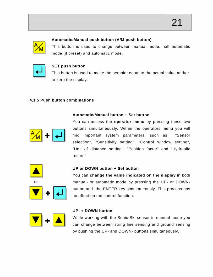
Automatic/Manual push button (A/M push button) This button is used to change between manual mode, half automatic
mode (if preset) and automatic mode.
SET push button
This button is used to make the setpoint equal to the actual value and/or
to zero the display.
4.1.5 Push button combinations
Automatic/Manual button + Set button You can access the operator menu by pressing these two
buttons simultaneously. Within the operators menu you will
find important system parameters, such as “Sensor
selection", “Sensitivity setting", “Control window setting",
“Unit of distance setting", “Position factor“ and “Hydraulic
record".
UP or DOWN button + Set button
You can change the value indicated on the display in both
manual- or automatic mode by pressing the UP- or DOWN-
button and the ENTER-key simultaneously. This process has
no effect on the control function.
UP- + DOWN button
While working with the Sonic-Ski sensor in manual mode you
can change between string line sensing and ground sensing
by pushing the UP- and DOWN- buttons simultaneously.

22 4.2 Switch on test
After switch-on the controller performs a display test. All
segments of the liquid crystal display, all light-emitting diodes of
the LED display and all four function lamps are illuminated for
about two seconds. If a button of the controller is pressed
during the switch-on test, the display shows the software
version for about 4 seconds. If any part of the diplay or one of
the LED's does not illuminate please inform your customer
service.
LOBAT
4.3 Sensor identification
After the switch-on test, the digital controller indicates the identification of the
sensor that was used last in an alternating display mode. The identification of the
various sensors are listed in those paragraphs dealing with their operation.
In addition to this, the two direction lamps will flash. After that, the controller
automatically changes over to the working mode.
Example of the sensor identification for the Sonic-Ski:
Important: If the sensor has been replaced or removed, the controller will clearly
indicate this with the message shown below. The operator should be informed about
this fact and about the need to check all settings for the new sensor when switching
on the system. Please acknowledge this message by pressing any button.

23
4.4 Operator menu
In the controller’s operator menu, you will find all parameters and settings that are
important for the control system in general and for the use of the various sensors.
Due to the fact that individual systems can have several
configurations, (depending on the application and the related selection of sensors),
the operator menu appears in a lot of different ways.
In order to avoid unnecessary confusion, menu points which are irrelevant
for the sensor combination actually used, will not be indicated when calling the
operator menu. Due to this, sometimes the operator menu has only 2 menu items;
other configurations may have up to 8, depending on the application.
The result of this is that in these operating instructions we cannot make a binding
statement regarding which parameter is to be found on which position. However,
identifying the various menu points with individual designations makes their
identification quite easy.
In the following, we will describe all menu points in their order of appearance in a
fully equipped and appropriately configurated system.
Listed in detail, these are:
Indication of cross slope;
Sensor selection;
3D set-point assignment;
Sensitivity setting;
Control window setting;
Unit of distance setting;
Position factor;
Hydraulic record;
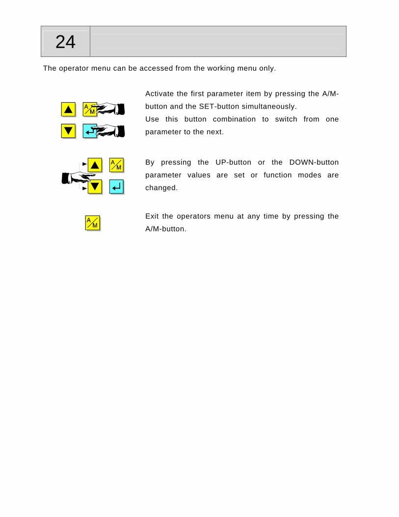
24 The operator menu can be accessed from the working menu only.
Activate the first parameter item by pressing the A/M-
button and the SET-button simultaneously.
Use this button combination to switch from one
parameter to the next.
By pressing the UP-button or the DOWN-button
parameter values are set or function modes are
changed.
Exit the operators menu at any time by pressing the
A/M-button.
25
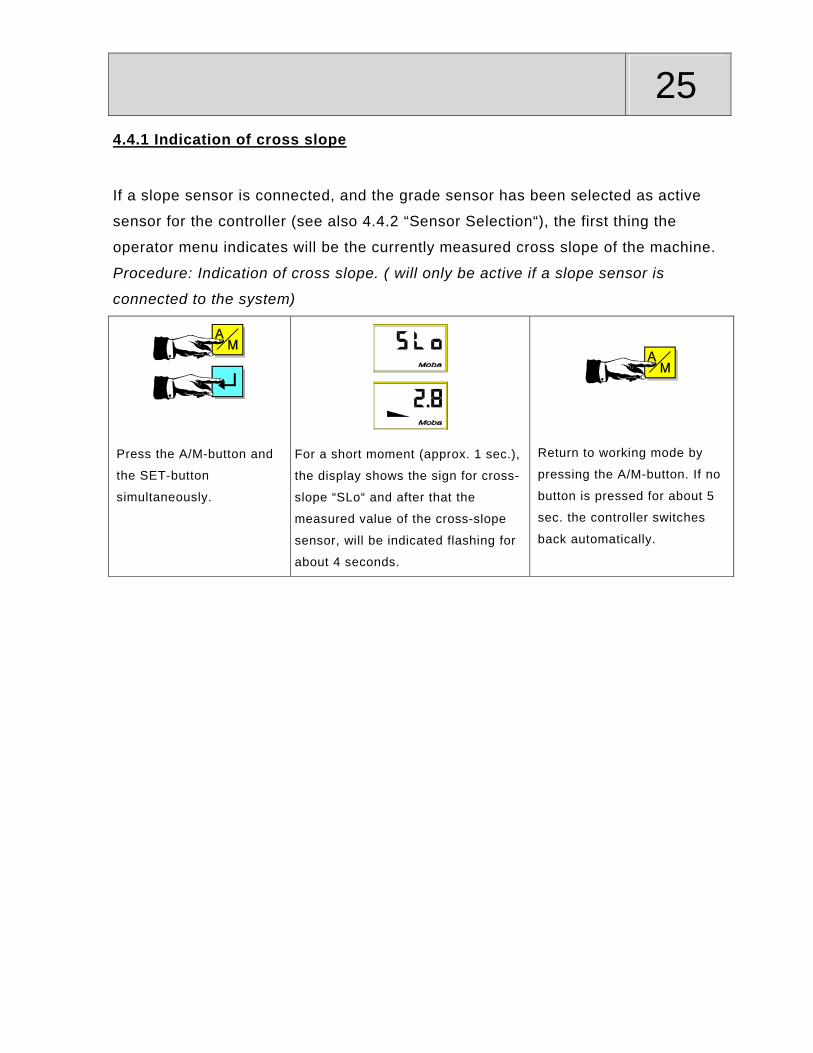
4.4.1 Indication of cross slope
If a slope sensor is connected, and the grade sensor has been selected as active
sensor for the controller (see also 4.4.2 “Sensor Selection“), the first thing the
operator menu indicates will be the currently measured cross slope of the machine.
Procedure: Indication of cross slope. ( will only be active if a slope sensor is
connected to the system)
Press the A/M-button and
the SET-button
simultaneously.
For a short moment (approx. 1 sec.),
the display shows the sign for cross-
slope “SLo“ and after that the
measured value of the cross-slope
sensor, will be indicated flashing for
about 4 seconds.
Return to working mode by
pressing the A/M-button. If no
button is pressed for about 5
sec. the controller switches
back automatically.
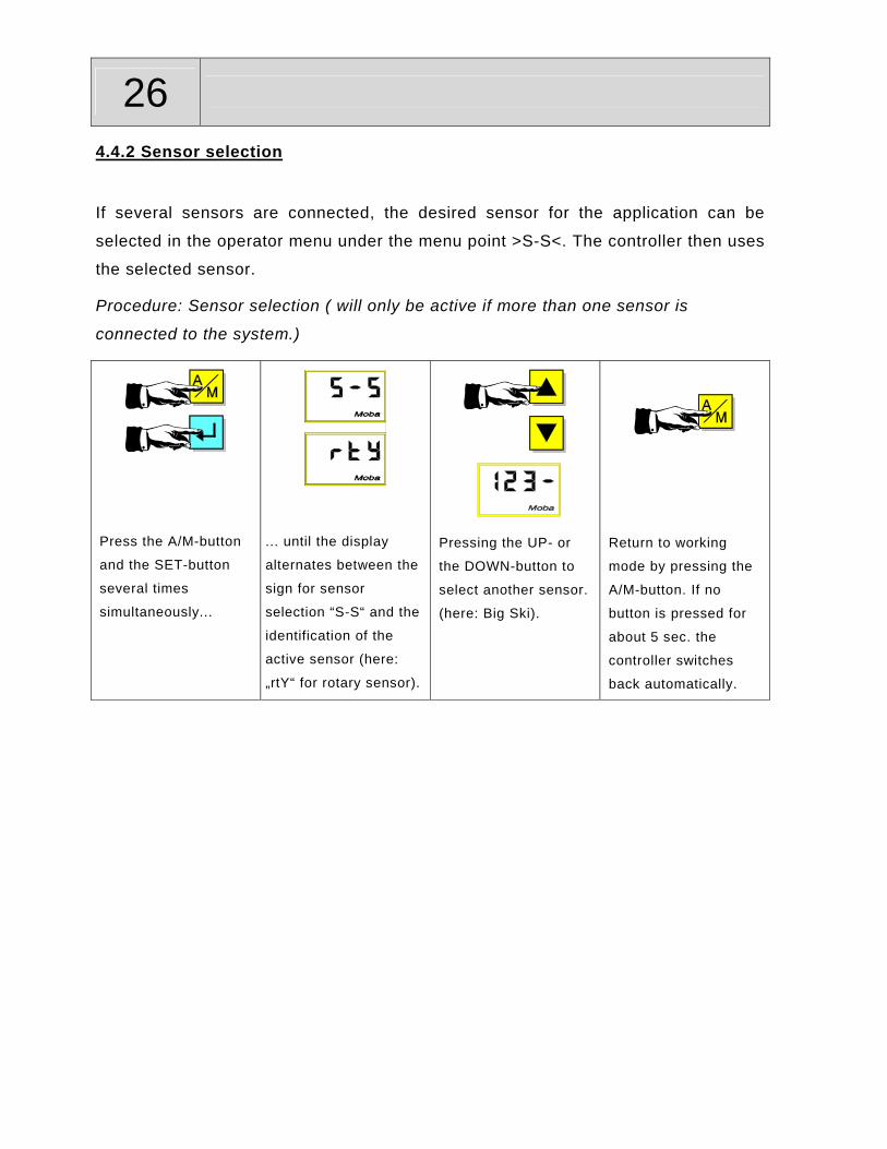
26 4.4.2 Sensor selection
If several sensors are connected, the desired sensor for the application can be
selected in the operator menu under the menu point >S-S<. The controller then uses
the selected sensor.
Procedure: Sensor selection ( will only be active if more than one sensor is
connected to the system.)
Press the A/M-button
and the SET-button
several times
simultaneously...
... until the display
alternates between the
sign for sensor
selection “S-S“ and the
identification of the
active sensor (here:
„rtY“ for rotary sensor).
Pressing the UP- or
the DOWN-button to
select another sensor.
(here: Big Ski).
Return to working
mode by pressing the
A/M-button. If no
button is pressed for
about 5 sec. the
controller switches
back automatically.

27
4.4.3 3D set-point assignment
If the controller receives external 3D set-point commands (e.g. because it is
integrated into a 3D-control system with GPS or a total-station), you can select here
whether these shall be used for control purposes or if changes are to be done the
conventional way – by manual entries from the keyboard.
A = automatic mode = 3D control;
Hd = manual mode = adjustment via keyboard entries;
Procedure: 3D set-point assignment. ( will only be active if a 3-D controller is
connected to the system.)
Press the A/M-button
and SET-button
several times
simultaneously ...
... until the display
alternates between the
sign for 3D set point
assignment “SP“ and
the current control
mode (here: “A“ for 3D
control).
Press the UP- or
DOWN-button for a
change-over to the
other control variant
(here: „Hd“ for manual
entries).
Return to working
mode by pressing the
A/M-button. If no
button is pressed for
about 5 sec. the
controller switches
back automatically.

28 4.4.4 Sensitivity setting
If MOBA-matic is operated with different sensor types (grade and slope sensors) the
sensitivity of the controller should be individually adjusted.
The range of adjustment of this menu point is always from 1 (low sensitivity) to 10
(high sensitivity). These figures are derived from an ingenious combination of the
control parameters “Deadband“ and “Propband“, which was determined by an
extensive test series and many years of expierence.
On the next pages, you will find a comparison of the respective values as well as an
explanation of what they stand for.
The sensitivity has to be adjusted separately for grade and slope sensors. If a
sensor has to be replaced at a later point of time, this value will be automatically
selected.
If MOBA-matic is too active in the automatic mode, the sensitivity needs to be
reduced on the respective digital controller. If MOBA-matic is too sluggish in the
automatic mode, the sensitivity needs to be increased.
Procedure: Sensitivity setting (Always available)
Press the A/M-button
and the SET-button
simultaneously several
times. ...
... until the display
alternates between the
sign „SE“ for sensitivity
setting and the value
that was adjusted last
(standard setting: „6“).
The value can be
increased or
decreased by pressing
the UP- or DOWN-
button (here: setting to
the value „7“).
Return to working
mode by pressing the
A/M-button. If no
button is pressed for
about 5 sec. the
controller switches
back automatically.
29
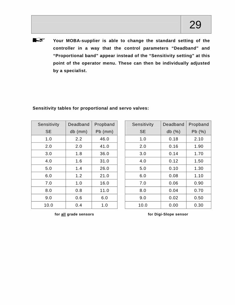
Your MOBA-supplier is able to change the standard setting of the
controller in a way that the control parameters “Deadband” and “Proportional band” appear instead of the “Sensitivity setting” at this point of the operator menu. These can then be individually adjusted by a specialist.
Sensitivity tables for proportional and servo valves:
Sensitivity SE
Deadband db (mm)
Propband Pb (mm)
Sensitivity SE
Deadband db (%)
PropbandPb (%)
1.0 2.2 46.0 1.0 0.18 2.10
2.0 2.0 41.0 2.0 0.16 1.90
3.0 1.8 36.0 3.0 0.14 1.70
4.0 1.6 31.0 4.0 0.12 1.50
5.0 1.4 26.0 5.0 0.10 1.30
6.0 1.2 21.0 6.0 0.08 1.10
7.0 1.0 16.0 7.0 0.06 0.90
8.0 0.8 11.0 8.0 0.04 0.70
9.0 0.6 6.0 9.0 0.02 0.50
10.0 0.4 1.0 10.0 0.00 0.30
for all grade sensors for Digi-Slope sensor
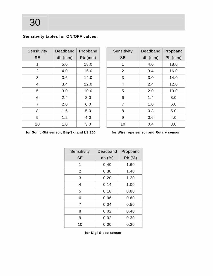
30 Sensitivity tables for ON/OFF valves:
Sensitivity SE
Deadband db (mm)
Propband Pb (mm)
Sensitivity SE
Deadband db (mm)
PropbandPb (mm)
1 5.0 18.0 1 4.0 18.0
2 4.0 16.0 2 3.4 16.0
3 3.6 14.0 3 3.0 14.0
4 3.4 12.0 4 2.4 12.0
5 3.0 10.0 5 2.0 10.0
6 2.4 8.0 6 1.4 8.0
7 2.0 6.0 7 1.0 6.0
8 1.6 5.0 8 0.8 5.0
9 1.2 4.0 9 0.6 4.0
10 1.0 3.0 10 0.4 3.0
for Sonic-Ski sensor, Big-Ski and LS 250 for Wire rope sensor and Rotary sensor
Sensitivity SE
Deadbanddb (%)
Propband Pb (%)
1 0.40 1.60
2 0.30 1.40
3 0.20 1.20
4 0.14 1.00
5 0.10 0.80
6 0.06 0.60
7 0.04 0.50
8 0.02 0.40
9 0.02 0.30
10 0.00 0.20
for Digi-Slope sensor

31
4.4.5 Control window setting
This menu point only appears if a grade sensor has been chosen as active sensor at
the menu point “Sensor selection”, because it only has effect on this type of sensor.
If a control deviation appears that is bigger than the set range this control deviation
will be recognised as a fault.
The display will show the symbol for the control window, both direction arrows of the
LC display and the complete LED arrow flash and the drive of the hyraulic cylinders
will be switched off.
The input is done in 0.1 cm, 0,1 inch or 0,01 feet steps, depending on which
physical unit for the distance measurements was set (see also the next section "Unit
of distance setting" of this operating instructions).
Procedure: Control window setting. (will only be active if a grade sensor is attached
and is selected)
Press the A/M-button
and the SET-button
several times
simultaneously ...
... until the display
alternates between the
symbol for the control
window ” “ and the
value entered last
(standard „OFF“ –
which means
deactivated).
The size of the control
window can be
adjusted by pressing
the UP- or DOWN-
button (here: setting to
the value “8.0“ (3.15”)
[± 4.0cm (1.575”)]).
Return to working
mode by pressing the
A/M-button. If no
button is pressed for
about 5 sec. the
controller switches
back automatically.

32 4.4.6 Unit of distance setting
This menu point only appears if a grade sensor has been chosen as active sensor at
the menu point “Sensor selection”, because it only has effect on this type of sensor.
Here, the operator can preset the desired measuring unit for the displayed distance
values. You can choose between the physical units”centimeter“, ”inch“ and “feet“.
Procedure: Unit of distance setting. (will only be active if a grade sensor is attached
and is selected)
Press the A/M-button
and the SET-button
several times
simultaneously ...
... until the display
alternates between the
sign „CAL“ for unit of
distance setting and
the measuring unit that
was entered last
(standard „CEn“ =
centimeter).
You can change from
one physical
measuring unit to
another by pressing
the UP- or the DOWN-
button (here: setting to
the unit „Inch“).
Return to working
mode by pressing the
A/M-button. If no
button is pressed for
about 5 sec. the
controller switches
back automatically.
33
4.4.7 Position factor
This menu point will only appear if a grade sensor has been chosen as active
sensor under menu point “Sensor selection“, since it only has an effect on this type
of sensor, and if this selection has been activated by your MOBA-supplier during the
setup of the controller. This setting is used primarily for milling machines.
Change in height of sensor x position factor = change in height of tool
How to determine the position factor:
Before we can enter a position factor, it has to be determined. In order to be able to
do so an understanding of the following is required.
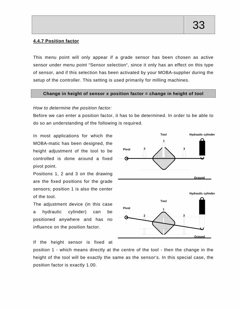
In most applications for which the
MOBA-matic has been designed, the
height adjustment of the tool to be
controlled is done around a fixed
pivot point.
Positions 1, 2 and 3 on the drawing
are the fixed positions for the grade
sensors; position 1 is also the center
of the tool.
The adjustment device (in this case
a hydraulic cylinder) can be
positioned anywhere and has no
influence on the position factor.
If the height sensor is fixed at
position 1 - which means directly at the centre of the tool - then the change in the
height of the tool will be exactly the same as the sensor‘s. In this special case, the
position factor is exactly 1.00.
1
2 3
1
2 3Pivot
Tool Hydraulic cylinder
Ground
Hydraulic cylinder
Tool
Pivot
Ground
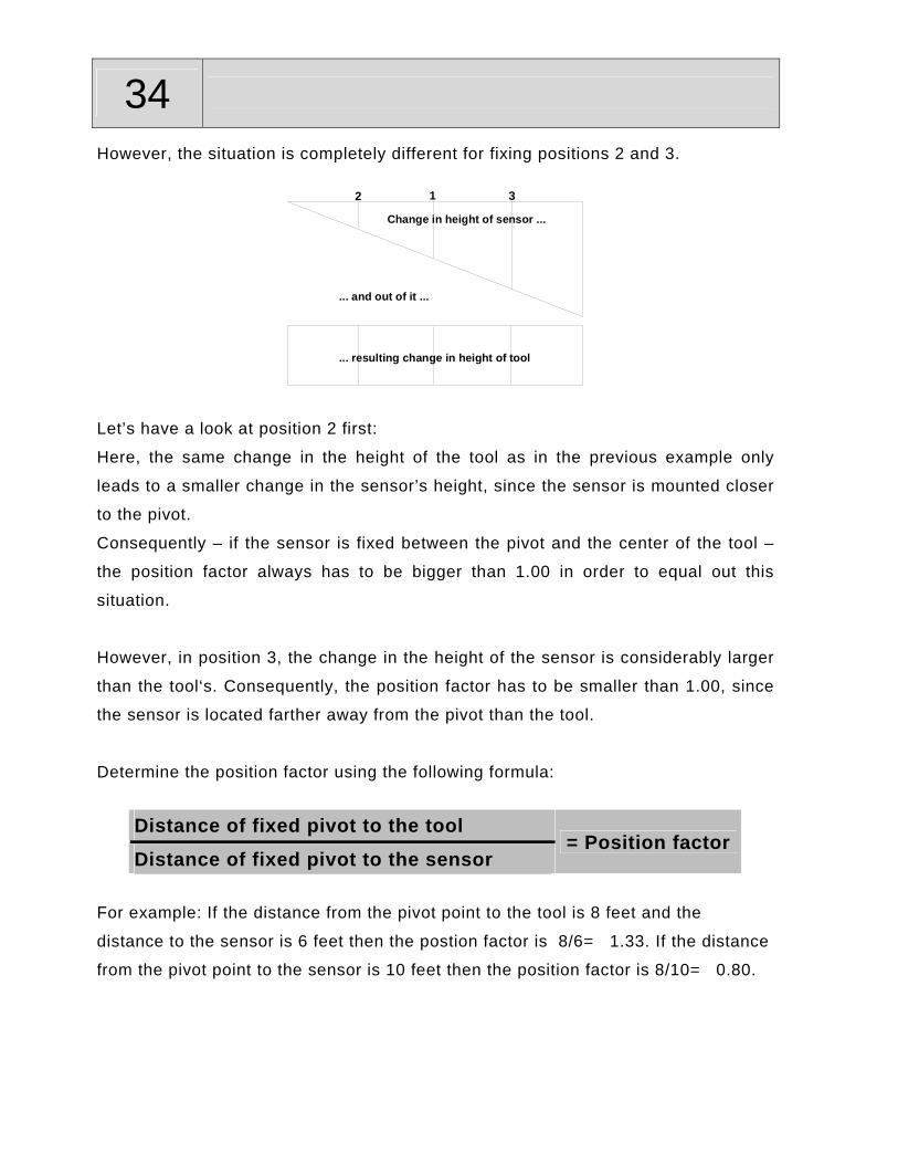
34 However, the situation is completely different for fixing positions 2 and 3.
12 3
Change in height of sensor ...
... resulting change in height of tool
... and out of it ...
Let’s have a look at position 2 first:
Here, the same change in the height of the tool as in the previous example only
leads to a smaller change in the sensor’s height, since the sensor is mounted closer
to the pivot.
Consequently – if the sensor is fixed between the pivot and the center of the tool –
the position factor always has to be bigger than 1.00 in order to equal out this
situation.
However, in position 3, the change in the height of the sensor is considerably larger
than the tool‘s. Consequently, the position factor has to be smaller than 1.00, since
the sensor is located farther away from the pivot than the tool.
Determine the position factor using the following formula:
Distance of fixed pivot to the tool
Distance of fixed pivot to the sensor = Position factor
For example: If the distance from the pivot point to the tool is 8 feet and the
distance to the sensor is 6 feet then the postion factor is 8/6= 1.33. If the distance
from the pivot point to the sensor is 10 feet then the position factor is 8/10= 0.80.
35
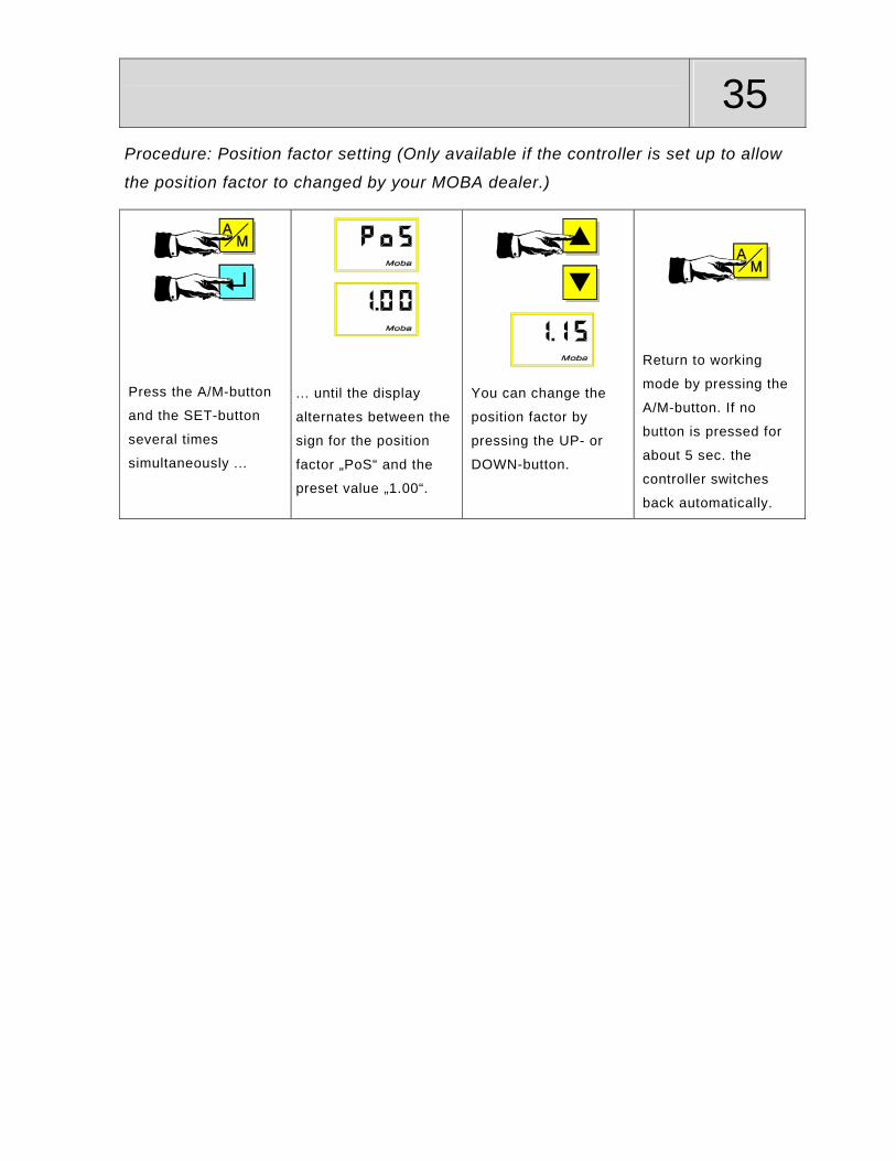
Procedure: Position factor setting (Only available if the controller is set up to allow
the position factor to changed by your MOBA dealer.)
Press the A/M-button
and the SET-button
several times
simultaneously ...
... until the display
alternates between the
sign for the position
factor „PoS“ and the
preset value „1.00“.
You can change the
position factor by
pressing the UP- or
DOWN-button.
Return to working
mode by pressing the
A/M-button. If no
button is pressed for
about 5 sec. the
controller switches
back automatically.
36 4.4.8 Hydraulic record
If the MOBA-matic system is to be used on several machines, it is possible for the
MOBA-agent to store different hydraulic parameter settings for up to 40 different
machine types (the maximum number of hydraulic types can be limited by your
MOBA-supplier during the initial setup of the controller).
Use menu point „Hydraulic record“ to load the stored settings for the corresponding
machine.
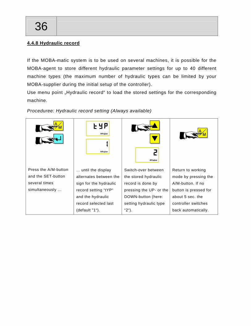
Proceduree: Hydraulic record setting (Always available)
Press the A/M-button
and the SET-button
several times
simultaneously ...
... until the display
alternates between the
sign for the hydraulic
record setting “tYP“
and the hydraulic
record selected last
(default ”1“).
Switch-over between
the stored hydraulic
record is done by
pressing the UP- or the
DOWN-button (here:
setting hydraulic type
“2“).
Return to working
mode by pressing the
A/M-button. If no
button is pressed for
about 5 sec. the
controller switches
back automatically.

37
4.4.9 Graphic representation of the operator menu
Working menu
Operator menu
5 sec.
Ext.3D set-pointassignment?
3D set-point assignment"SP / A "
Sensitivity mode SE = OFF?
Deadband"db / 0.2 or 0.04"
Sensitivity"SE / 6"
Control window" / OFF"
Unit of distance"CAL / CEn"
Hydraulic record"tYP / X"
yes
(1 - 10 or1.0 - 10.0 with Prop and Servo)
(2.0cm - 20.0cm / OFF or 0.8inch - 8.0inch / OFF or 0.06Ft - 0.66Ft / OFF)
(CEn / inch / Ft)
(1 - set limit)
(SLo / LAS / rop / rtY / Son / / 123 / 1-3 / 3d)
yes
Grade sensor selected? yes
Several sensors connected?
Sensor selection"S-S / e.g. rop"
yes
Grade selected & Slope
connected?
Indication of cross slope"SLo / e.g. 1.20"
yes
Propband"Pb / 1.0 or 1.0"
(Hd / A)
(0.0cm - 4.0cm with Grade or 0.00% - 4.00% with Slope )
(0.0cm - 40.0cm with Grade or 0.0% - 40.0% with Slope )
Positionfactor Po.S = on
& no 3D?
Position factor"PoS / 1.00"
yes
(0.60 - 1.50)

38 4.5 Different user settings
Your MOBA-agent can set the operation of the controller, selecting from three
possibilities. The differences are the follows:
STANDARD Set point setting The setpoint can be changed with the UP/DOWN-buttons. In automatic mode the setpoint changes continuously in 1mm, 0.1 inch or 0.01 foot steps. ATTENTION! The tool is driven. The changed setpoint is indicated at the display.
Indicated value
By pressing the SET-button together with the UP- or DOWN-button the displayed value can be altered without affecting the position of the tool.
HALF AUTOMATIC (Changing the setpoint without active control outputs) Set point setting The setpoint can be changed with the UP/DOWN-buttons. In automatic mode and half automatic mode the setpoint changes continuously in 1mm, 0.1 inch or 0.01 foot steps. steps. ATTENTION! In automatic mode the tool is driven. The changed setpoint is indicated at the display.
Indicated value
By pressing the SET-button together with the UP- or DOWN-button the indicated value can be altered without affecting the position of the tool.
The switch over between manuel, half automatic and automatic mode is done continuously by pressing the A/M-button.
manualLED offControl outputs inactiveNo setpoint changing
half automaticLED flashingControl outputs inactiveSetpoint changing possible
automaticLED onControl outputs activeSetpoint changing possible
AUTO ZERO Set point setting The setpoint can be changed with the UP/DOWN-buttons. In automatic mode the setpoint changes in 2mm0.1 inch or 0.01 foot steps with every push on the button. ATTENTION! In automatic mode, the tool is driven. After 5 seconds, the value in the display is stored as zero point.
Indicated value

39
The following operating instructions for the various sensors is based on the
controller’s standard presetting (see previous page).
Specific differences in the user settings (such as the half automatic mode or
different step sizes for the set point adjustment) have no influence on the general
operating procedures.

40 5. The Digi-Slope sensor
5.1 Description
The Digi-Slope sensor works with a very precise, electro-mechanical measuring
instrument and is used to detect the tool’s slope. Sensor identification:
After switch-on or if a sensor has been changed, the display alternates between the
sign for the Digi-Slope sensor and the side identification (right = right or left = left).
=
5.2 Mounting
The Digi-Slope sensor needs to be mounted on a part of the machine that moves
with all slope changes in the same way as the tool does.
With milling machines, the lower the sensor is the better. (e.g. on the milling drum
housing); in case of a paver, we recommend the cross linkage (transverse beam)
between the tow arms.
For mounting purposes, four fixing holes are provided in the fixing plate of the
sensor (for drawing, see paragraph 13 “Technical data“). Shock absorbers should be
installed between the mounting plate and the chassis.
The connectors must be accessible, so that the interconnecting cable can be easily
plugged in. Please observe the direction of mounting (FWD/arrow in direction of
travel).

41
5.3 Operation of the Digi-Slope sensor
It is assumed that the Digi-Slope sensor and the digital controller are mounted, the
cables are connected and the digital controller has its voltage supply. After the
switch-on message, the digital controller indicates the sensor identification. As soon
as the message of the connected sensor disappears, the system will be operable. If
the sensor is being used for the first time or has been changed, the sensor
identification must be acknowledged by pressing any one of the push buttons.
Select a sensor as described in the previous chapter, if necessary.
Procedure: Acknowledgement of the sensor identification
The digital controller
indicates the sensor
identification (here:
right).
The digital controller
indicates the sensor
identification (here:
left).
If the sensor is
connected for the first
time or has been
replaced, the sensor
identification has to be
acknowledged by
pressing any button.
1b 2
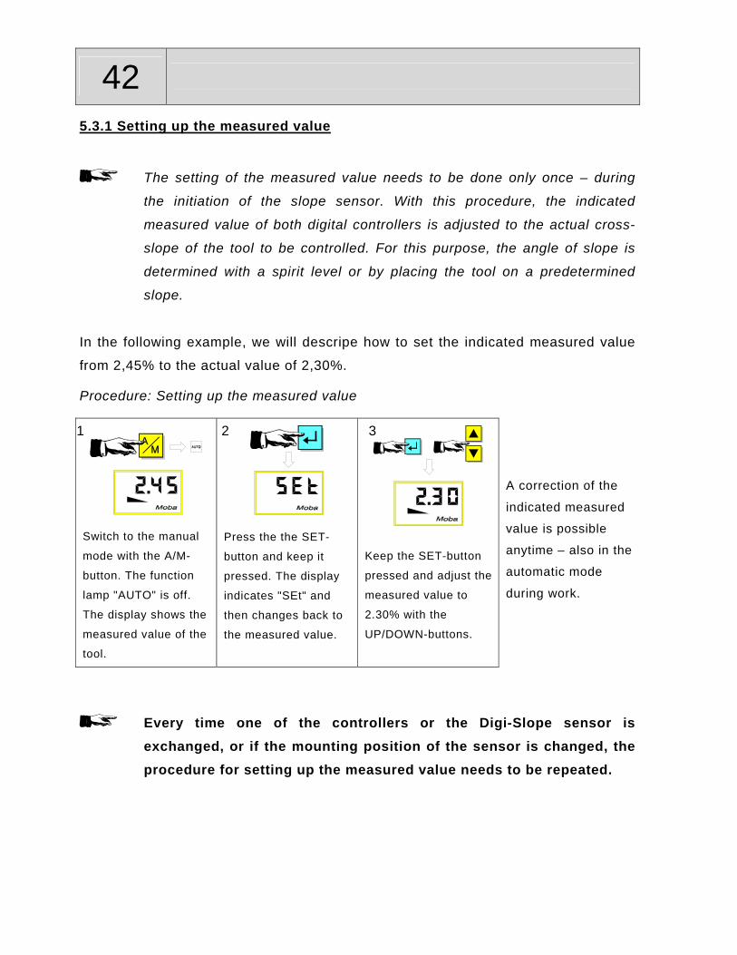
42 5.3.1 Setting up the measured value
The setting of the measured value needs to be done only once – during
the initiation of the slope sensor. With this procedure, the indicated
measured value of both digital controllers is adjusted to the actual cross-
slope of the tool to be controlled. For this purpose, the angle of slope is
determined with a spirit level or by placing the tool on a predetermined
slope.
In the following example, we will descripe how to set the indicated measured value
from 2,45% to the actual value of 2,30%.
Procedure: Setting up the measured value
Switch to the manual
mode with the A/M-
button. The function
lamp "AUTO" is off.
The display shows the
measured value of the
tool.
Press the the SET-
button and keep it
pressed. The display
indicates "SEt" and
then changes back to
the measured value.
Keep the SET-button
pressed and adjust the
measured value to
2.30% with the
UP/DOWN-buttons.
A correction of the
indicated measured
value is possible
anytime – also in the
automatic mode
during work.
Every time one of the controllers or the Digi-Slope sensor is exchanged, or if the mounting position of the sensor is changed, the procedure for setting up the measured value needs to be repeated.
1 2 3

43
5.3.2 Controlling with the Digi-Slope sensor
It is assumed that the Digi-Slope sensor is mounted, the cables are connected and
the setting of the measured value is done.
Procedure: Controlling with the Digi-Slope sensor
Bring the tool into working position with the UP/DOWN-buttons at the controller or with the operating unit at the machine.
Switch over to the manual mode with the A/M-button. The function lamp "AUTO" is off.
(here: 5,35%, slope to the
right)
Now the SET-button must be pressed to set the angle of slope of the tool as set point . The display indicates "SEt".
Attention: It is absolutely essential to carry
out step no. 3. If disregarded, this will
move the tool into an undefined position
when switching over to automatic mode.
The set point can be changed step by step using the UP/DOWN-buttons. The controller will then control to this new value.
The display indicates the measured value again.
Switch to the automatic mode by pressing the A/M-button. The function lamp "AUTO" is on.
The controller now indicates 5.35% as set point. The controller now controls to this value. A control deviation will be indicated with the RAISE/LOWER-arrows.
(here: 6.00%, right slope)
At any time you can switch back to the measured value in order to check the tool’s slope by pressing the A/M-button. However, the automatic drive of the valves will then be switched off.
Sensitivity setting
If the control in automatic mode is too sluggish or too active the
sensitivity setting should be changed accordingly. The procedure
is described in section 4.4.4 of these operating instructions.
1 2 3
4 5 6 7

44 6.The Sonic-Ski sensor
6.1 Description
The Sonic-Ski sensor is used for non-contacting elevation control. It uses 6
ultrasonic elements, 5 for elevation measurements and 1 for temperature
compensation. Sensor identification:
After switch-on or if a sensor has been changed, the display alternates between the
symbol for the Sonic-Ski and the sign for sensor.
=
6.2 Mounting instructions and working range
The Sonic-Ski can be mounted easily and quickly using simple tools. For this
purpose, a fastening tube should be fitted at a suitable position (paver: on the tow
arm; milling machine: on the frame). Procedure:
1. Loosen the locking handles on the mounting
tube.
2. Insert the center pivot of the sensor into the
mounting tube.
3. Turn the sensor housing according to the
required direction of travel.
4. Fix the center pivot with the locking handle.

45
Direction of travel: The direction of travel of the Sonic-Ski is
determined as follows:
When ground sensing, the Sonic-Ski
should work in parallel to the direction of
travel. (averaging is done by the Sonic-
Ski).
Single sensing
resulting road surface
Averaging of the Sonic-Ski
Direction
resulting road surface
When string line sensing, the Sonic-Ski
should operate perpendicular to the
direction of travel, so that the full working
width of 25 cm is available.
Ground sensing String line sensing
The working range:
The working range for ground- and string
line sensing is between 30cm and 40cm
(11.75 in and 15.75in).
In this range, the measured value is
indicated with a constant display,
otherwise the display flashes (positioning
aid).
The Sonic-Ski should be adjusted at a
distance of approx.. 35 cm (13.75in) from
the reference.
Ground String line
ca. 35cm

46 6.3 Working with the Sonic-Ski sensor
It is assumed that the Sonic-Ski and the digital controller are mounted, the cables
are connected and the digital controller has its voltage supply. After the switch-on
message, the digital controller indicates the type of sensor. As soon as this
message disappears automatically, the system is ready for work. If the sensor is
used for the first time or has been changed, the sensor identification must be
acknowledged by pressing any one of the push buttons. If necessary, select this
sensor as described in section 4.
Procedure: Acknowledgement of the sensor identification
The digital controller
indicates the sensor
identification of the
Sonic-Ski.
If the sensor is connected
for the first time or has
been changed, the sensor
identification must be
acknowledged by pressing
any button.
At this point we want to remind you once again of the working directions
for ground- and string line sensing and the optimal work range of the
Sonic-Ski. Both specifications have to be strictly observed in order to
obtain optimal results.
Ground sensing String line sensing

47
6.3.1 String line sensing
Procedure: String line sensing
Switch to the manual mode with the A/M-button. The function lamp "AUTO" is off.
The string line mode is activated by pressing the UP/DOWN-buttons simultaneously. The string line lamp is on.
For zero setting, bring the tool into working position using the UP/DOWN-buttons at the controller or the operating unit at the machine.
String line
ca. 35cm
Position the Sonic-Ski 35 cm above the string line (measured value indication is constantly on).
The Sonic-Ski has to be positioned in the middle above the string line (both direction arrows off). Lamps off = string line in the middle / lamp on = string line in half middle / lamp flashes = string line outside. Readjust the Sonic-Ski, if the string line is out of range.
Now, the SET-button is pressed. If pressed for a short time, the display indicates "SEt" and the actually measured value is stored as set point.
> 1,5 Sek.
If the SET-button is pressed for more than 1,5 seconds, the display changes from "SEt" to "0.0" and the measured value and the set point are both set to zero.
Switch to the automatic mode with the A/M-button. The function lamp "AUTO" is on.
The controller keeps the tool at the adjusted value.
In order to be able to make corrections, the set point can be changed in the automatic mode using the UP/DOWN-buttons.
You can switch back to manual mode anytime with the A/M-button. The automatic control of the valves will then be switched off.
Adjustment and indication of the set point differ according to the selected operation mode (see also section 4.5 „Different user settings“).
3 4 1 2
6b 7 5 6a
8 9

48 6.3.2 Ground sensing
Proceduree: Ground sensing
Switch to the manual mode using the A/M-button. The function lamp "AUTO" is off.
The ground mode is activated by pressing the UP/DOWN-buttons simultaneously. The string line lamp is off.
For zero setting, bring the tool into working position using the UP/DOWN-buttons at the controller or the operating unit at the machine.
Ground
ca. 35cm
Position the Sonic-Ski 35 cm above the ground (measured value indication has to be constantly on).
The two direction arrows are without any meaning when in the ground sense mode.
Now, the SET-button is pressed. If pressed for a short time, the display indicates "SEt" and the actually measured value is stored as set point.
> 1,5 Sek.
If the SET-button is pressed for more than 1,5 seconds, the display changes from "SEt" to "0.0" and the measured value and the set point are both set to zero.
Switch to the automatic mode with the A/M-button. The function lamp "AUTO" is on.
The controller keeps the tool at the adjusted value.
In order to make corrections, the set point can be changed in the automatic mode using the UP/DOWN-buttons.
You can switch back to manual mode anytime with the A/M-button. The automatic control of the valves will then be switched off.
Adjustment and indication of the set point differ according to the selected operation mode (see also section 4.5 „Different user settings“).
3 4 1 2
6b 7 5 6a
8 9

49
Sensitivity If the control is too sluggish or too active in the automatic mode, the sensitivity
setting should be changed accordingly (see section 4.4.4 of these operating
instructions).
Control window The control window is active in both operating modes (string line- and ground
sensing). The setting of the control window is described in section 4.4.5 of these
operating instructions.

50 7. The Rotary sensor
7.1 Description
The rotary sensor is used for elevation control and senses its measured values from
an existing reference by use of mechanical means. This may be a string line or the
surface (e.g. road surface). Sensor identification:
After switch-on or if a sensor has been changed, the display alternates between the
sign for Rotary and the sign for sensor.
=
7.2 Mounting instructions and possible applications
Two aids are available for sensing the different references. The sensing tube is
used when sensing a string line; the sensing ski when sensing a surface.
Mounting the sensing tube to the sensing arm
Loosen the nut at the end of the sensing tube.
Slide the sensing tube into the fastening ring of the sensing arm.
Secure the sensing tube with the nut.

51
Mounting the sensing ski to the sensing arm
1. Loosen the security pin from the sensing ski bolt; remove bolt.
2. Insert the sensing arm with the fastening ring into the ski fastening.
3. Insert the bolt through the ski fastening and the fastening ring.
4. Secure the bolt with the security pin.
Mounting the sensing arm to the Rotary Sensor
1. Turn the flat side of the axle towards the side opposite
of the plug.
2. Loosen the sensing arm locking screw.
3. Fit the sensing arm onto the axle.
4. Tighten the locking screw to the flat part of the axle.
The Rotary Sensor can be mounted quickly and easily
with simple tools. For this purpose, a fastening tube should be fitted at a suitable
position (paver: tow arm at the height of the material auger; milling machine: at the
chassis above the milling drum). Procedure:
1. Loosen the adjustable clamping handle on
the mounting tube.
2. Insert the center pivot of the sensor into the
mounting tube.
3. Turn the sensor housing according to the
direction of travel (connector plug in direction of
travel).
4. Fix the center pivot with the locking screw or
screws.

52 String line sensing (with sensing tube):
Set the counterweight in a way that the sensing tube exerts a slight pressure on the
string line in downward direction. If the string line used as a reference does not
have enough tension, the sensing tube can be set up below the string line. For this
purpose, the counterweight has to be adjusted in a way that the sensing tube exerts
a slight pressure onto the string line in upward direction.
Ground sensing (with sensing ski):
Set the counterweight so that the the sensing ski exerts a slight pressure onto the
reference.
String line
Reference surface

53
7.3 Working with the Rotary sensor
It is assumed that the Rotary Sensor and the digital controller are mounted, all
cables are connected and that the digital controller has its voltage supply. After the
switch-on message, the digital controller indicates the type of sensor. As soon as
the identification disappears, the system is operable. If the sensor is being used for
the first time or has been changed, the sensor identification has to be acknowledged
by pressing any one of the push buttons. If necessary, select a sensor as described
in section 4.
Procedure: Acknowledgement of the sensor identification
The digital controller
indicates the sensor
identification.
If the sensor is connected
for the first time or has
been changed, the sensor
identification has to be
acknowledged by pressing
any button.
ATTENTION!
Please pay attention to the pressure the
sensing tubes exerts onto the string line or the sensing ski exerts
onto the ground.

54 7.3.1 String line sensing
Procedure: String line sensing
Press the A/M-button to switch to the manual mode. The function lamp "AUTO" is off.
For zero setting, bring the tool into working position using the UP/DOWN-buttons at the controller or the operating unit at the machine.
String line
The sensing tube must exert a slight pressure onto the string line. The pressure can be adjusted with the counterweight.
Now, the SET-button is pressed. If pressed for a short time, the display indicates "SEt" and the actually measured value is stored as set point.
> 1,5 Sek.
If the SET-button is pressed for more than 1,5 seconds, the display changes from "SEt" to "0.0" and the measured value and the set point are both set to zero.
Switch to the automatic mode with the A/M-button. The function lamp "AUTO" is on.
The controller keeps the tool at the adjusted value.
In order to make corrections, the set point can be changed in the automatic mode using the UP/DOWN-buttons. ATTENTION! Each adjustment changes the weight force of the sensing tube!
You can switch back to manual mode anytime with the A/M-button. The automatic control of the valves will then be switched off.
Adjustment and indication of the set point differ according to the selected operation mode (see also section 4.5 „Different user settings“).
3 4a 1 2
6 7 4b 5

55
7.3.2 Ground sensing
Procedure: Ground sensing
Press the A/M-button to switch to manual mode. The function lamp "AUTO" is off.
For zero setting, bring the tool into working position using the UP/DOWN-buttons at the controller or the operating unit at the machine.
Ground
The sensing ski has to exert a slight pressure onto the ground. The pressure can be adjusted with the counterweight.
Now, the SET-button is pressed. If pressed for a short time, the display indicates "SEt" and the actually measured value is stored as set point.
> 1,5 Sek.
If the SET-button is pressed for more than 1,5 seconds, the display changes from "SEt" to "0.0" and the measured value and the set point are both set to zero.
Switch to automatic mode with the A/M-button. The function lamp "AUTO" is on.
The controller keeps the tool at the adjusted value.
In order to make corrections, the set point can be changed in the automatic mode using the UP/DOWN-buttons. ATTENTION! Each adjustment changes the weight force of the sensing ski!
You can switch back to manual mode anytime with the A/M-button. The automatic control of the valves will then be switched off.
Adjustment and indication of the set point differ according to the selected operation mode (see also section 4.5 „Different user settings“).
3 4a 1 2
6 7 4b 5

56 Sensitivity If the control system is too sluggish or too active in the automatic mode, the
sensitivity should be changed accordingly. (see section 4.4.4 of these operating
instructions).
Control window When operating the digital controller with the Rotary Sensor, the control window is
active. The setting of the control window is described in section 4.4.5 of these
operating instructions.

57
8. The Wire Rope sensor (YOYO)
8.1 Description
The wire rope sensor is mainly used in connection with the milling machine. It is
used for elevation control and has a measuring range of 50 cm (19.68 inches). Sensor identification:
After switch-on or if a sensor has been changed, the display alternates between the
sign for wire rope and the sign for sensor.
=
8.2 Mounting
There are mounting holes on the side of the machine, above the milling drum (for a
drawing of the sensor housing, see section 13 ”Technical data“). There, the sensor
is installed with the rope outlet downwards (so that no moisture can seep in). The
rope can be pulled out approximately 50 cm (19.5”) and is hung or fixed at the
designated place at the side shield of the milling machine.
When working with the milling machine with completely lowered side
shield, the rope of the wire rope sensor should always be pulled out up to
approx. 3 cm (1.18”), in order to make use of the maximum measuring
range of the sensor.

58 For other applications, the rope should be fixed in a way that a maximum working
range is available for the intended application.
The rope inlet in relation to the outlet must always be done vertically to the sensor.
Right:
Wrong:

59
8.3 Working with the Wire Rope sensor
It is assumed that the wire rope sensor and the digital controller are mounted, the
cables are connected and the digital controller has its voltage supply. After the
switch-on message, the digital controller indicates the sensor identification. As soon
as the message disappears, the system will be operable. If the sensor is being used
for the first time or has been changed, the sensor identification has to be
acknowledged by pressing any one of the push buttons. If necessary, select this
sensor as described in section 4.
Procedure: Acknowledgement of the sensor identification
The digital controller
indicates the sensor
identification.
If the sensor is connected
for the first time or has
been changed, the sensor
identification has to be
acknowledged by pressing
any button.

60 8.3.1 Controlling with the Wire Rope sensor
Procedure: Controlling with the Wire Rope sensor
Press the A/M-button to switch to the manual mode. The function lamp "AUTO" is off.
For zero setting, bring the tool into working position using the UP/DOWN-buttons at the controller or the operating unit at the machine.
Check the fixing of the rope: Is the working range big enough for the intended application?
Now, the SET-button is pressed. If pressed for a short time, the display indicates "SEt" and the actually measured value is stored as set point.
> 1,5 Sek.
If the SET-button is pressed for more than 1,5 seconds, the display changes from "SEt" to "0.0" and the measured value and the set point are both set to zero.
Switch to the automatic mode with the A/M-button. The function lamp "AUTO" is on.
The controller keeps the tool at the adjusted value.
In order to be able to make corrections, the set point can be changed in the automatic mode using the UP/DOWN-buttons.
You can switch back to manual mode anytime with the A/M-button. The automatic control of the valves will then be switched off.
Adjustment and indication of the set point differ according to the selected operation mode (see also section 4.5 „Different user settings“).
3 4a 1 2
6 7 4b 5

61
Sensitivity If the control is too sluggish or too active in the automatic mode, the sensitivity
should be changed accordingly (see section 4.4.4 of these operating instructions).
Control window When operating the digital controller with a wire rope sensor, the control window is
active. The control window setting is described in section 4.4.5 of these operating
instructions.

62 9. The laser receiver LS 250
9.1 Description
The laser receiver is a sensor used for elevation control, which is suitable for all
standard rotation lasers such as red light transmitters (helium, neon) and infra red
transmitters. Among other applications, it is used for the construction of sports fields
and has a range of reception of approx. 25 cm. Sensor identification:
After switch-on or if a sensor has been changed, the controller display alternates
between the sign for the Laser receiver LS 250 and the sign for sensor.
=
9.2 Mounting instructions
In order to mount the laser receiver, a mast should be available on the machine.
The best place of installation at the milling machine is the outside of the machine,
above the milling drum axle. For a paver, it would be the outer edge of the screed,
slightly ahead of the auger.
The mast for the laser receiver should have a diameter of 45mm.

63
Make sure that the Laser Receiver is mounted high enough so that no obstacles can
come between the laser transmitter and the Laser Receiver. Also reflections of the
transmitter due to smooth surfaces near the receiver should be avoided.
The LS 250 is a linear Laser Receiver. The working point can be set and changed
easily with a simple push button action. Nevertheless the LS 250 should be mounted
so that the laser transmitter strikes it in the center. So that there is the possibility to
change the working point over the hole range.
It is realy easy to mount the LS 250:
1. Open the clamp.
2. Slide the LS 250 over the mast tube.
3. Tighten the clamp.
1 2 3
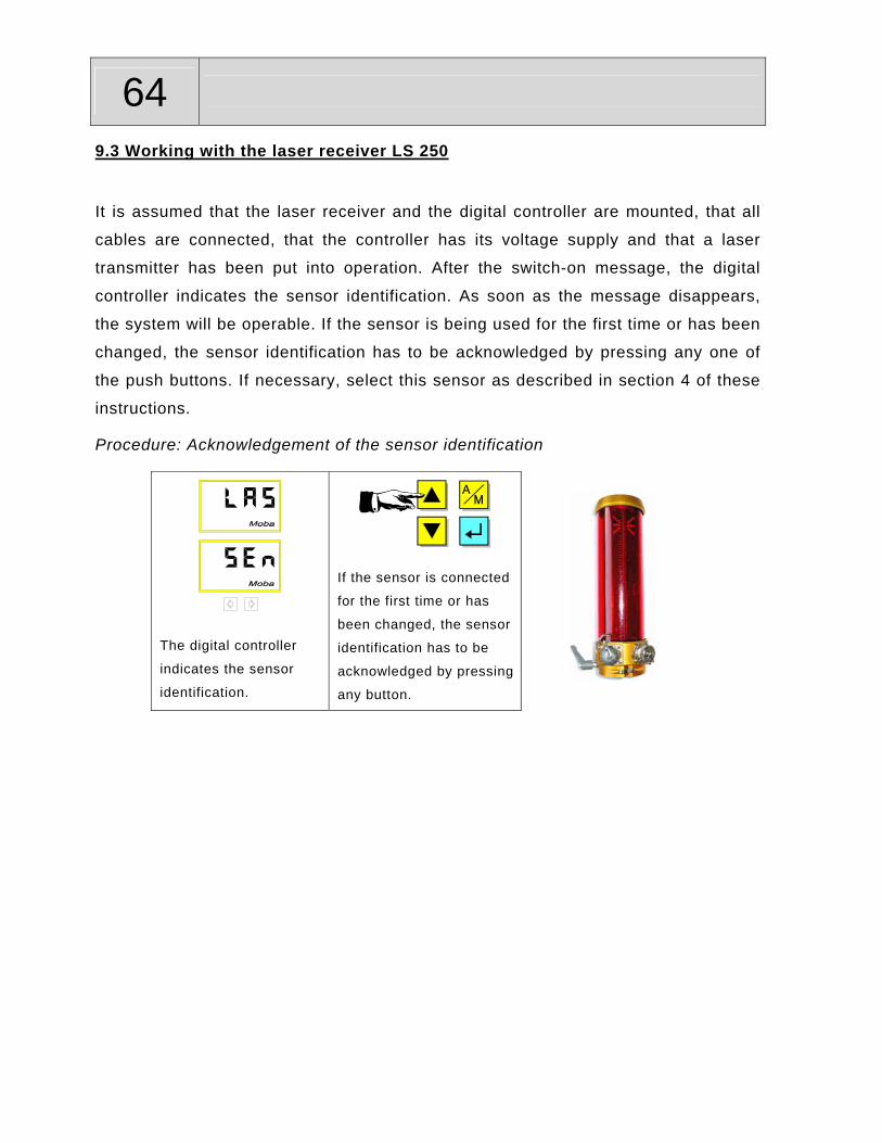
64 9.3 Working with the laser receiver LS 250
It is assumed that the laser receiver and the digital controller are mounted, that all
cables are connected, that the controller has its voltage supply and that a laser
transmitter has been put into operation. After the switch-on message, the digital
controller indicates the sensor identification. As soon as the message disappears,
the system will be operable. If the sensor is being used for the first time or has been
changed, the sensor identification has to be acknowledged by pressing any one of
the push buttons. If necessary, select this sensor as described in section 4 of these
instructions.
Procedure: Acknowledgement of the sensor identification
The digital controller
indicates the sensor
identification.
If the sensor is connected
for the first time or has
been changed, the sensor
identification has to be
acknowledged by pressing
any button.

65
9.3.1 Controlling with the laser receiver LS 250
Procedure: Controlling with the laser receiver LS 250
Press the A/M-button to switch to the manual mode. The function lamp "AUTO" is off.
For zero setting, bring the tool into working position using the UP/DOWN-buttons at the controller or the operating unit at the machine.
Now set the laser receiver so that the laser beam touches in the middle (observe the built in display.)
If the laser beam does not touch the receiver window, the receiver has to be shift in height until one of the LEDs at the LS 250 lights up.
The laser receiver ...
... has to be moved down.
... is set up correctly.
... must be moved up.
Now, the SET-button is pressed. If pressed for a short time, the display indicates "SEt" and the actually measured value is stored as set point.
> 1,5 Sek.
If the SET-button is pressed for more than 1,5 seconds, the display changes from "SEt" to "0.0" and the measured value and the set point are both set to zero.
3a 1 2 3b
4a 3c 4b

66
Switch over to the automatic mode with the A/M-button. The function lamp "AUTO" is on.
The controller keeps the tool at the adjusted value.
In order to be able to make corrections, the set point can be changed in the automatic mode using the UP/DOWN-buttons.
You can switch back to manual mode anytime with the A/M-button. The automatic control of the valves will then be switched off.
Adjustment and indication of the set
point differ according to the
selected operation mode (see also
section 4.5 „Different user
settings“).
Sensitivity If the control works too sluggishly or too unstable in the automatic mode, the
sensitivity should be changed accordingly. (see section 4.4.4 of these operating
instructions).
Control window The control window is active when the laser receiver LS 250 is in operation. The
control window setting is described in section 4.4.5 of these operating instructions.
6 7 5
67
10. The Big-Ski
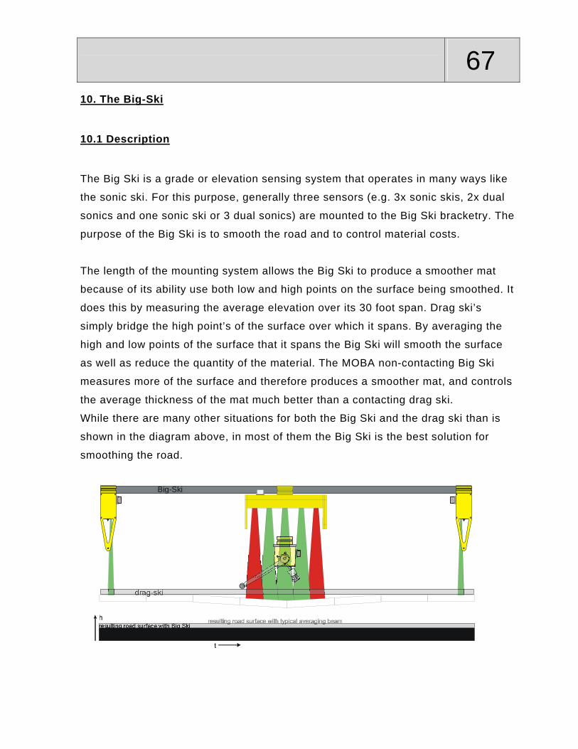
10.1 Description
The Big Ski is a grade or elevation sensing system that operates in many ways like
the sonic ski. For this purpose, generally three sensors (e.g. 3x sonic skis, 2x dual
sonics and one sonic ski or 3 dual sonics) are mounted to the Big Ski bracketry. The
purpose of the Big Ski is to smooth the road and to control material costs.
The length of the mounting system allows the Big Ski to produce a smoother mat
because of its ability use both low and high points on the surface being smoothed. It
does this by measuring the average elevation over its 30 foot span. Drag ski’s
simply bridge the high point’s of the surface over which it spans. By averaging the
high and low points of the surface that it spans the Big Ski will smooth the surface
as well as reduce the quantity of the material. The MOBA non-contacting Big Ski
measures more of the surface and therefore produces a smoother mat, and controls
the average thickness of the mat much better than a contacting drag ski.
While there are many other situations for both the Big Ski and the drag ski than is
shown in the diagram above, in most of them the Big Ski is the best solution for
smoothing the road.
Big-Ski
drag-ski
resulting road surface with Big Ski

68 Sensor identification:
After the system is powered up or if a sensor has been changed, the controller
display alternates between the numerical indication – figures 1 to 3 which stands for
the sensors and “Sen”. If one of the sensors is not connected or if there bad cable to
the sensor or a bad sensor the controller will indicate the bad sensor element as
shown in the table below.
=

69
10.3.2 Electrical system
When working with machines that are prewired, the connection of 3 sensors in order
to build a Big-Ski is no problem since appropriately coded connector plugs are
provided at the front, in the middle and at the back of the machine side. The
consecutive numbering, which the indication on the controller display refers to, is
always done from the front to the back (in direction of travel).
Please only use Sonic-Ski or dual sonicsensors at positions 1 and 3 – i.e. at the front and the back.
z.B.:
1 2 3
Connecting the Big-Ski to a global-version controller is not complicated.
In this case, the 3 sensors are connected to the controller by means of the “Big-Ski
junction box“ with appropriately coded connector plugs.

70 The junction box should be mounted in a way that a simple wiring to the controller
and the sensors is possible. The connectors for the sensors should always point
downwards, so that no water can seep into the junction box. All inputs that are not
used, should be sealed with dust protection caps.
Connect the digital controller with the input of the junction box. After that, connect
the desired sensor combination to the outputs of the junction box as described
below. The front sensor (as seen from direction of travel) is connected to output 1,
the middle one to output 2 and the one at the back to ouput 3.
This order is the basis for the numerical indication on the controller display during
sensor identification.
Please only use Sonic-Ski or dual sonic sensors at positions 1 and 3 – i.e. at the front and the back.
12
3
1 2 3
z.B.:

71
10.4 Set-up
With the Big-Ski, only ground sensing is possible.
Therefore, all Sonic-Skis have to work parallel to the direction
of travel in order to obtain optimal results.
When working with the Big-Ski, the optimal working range of
the Sonic-Ski has to be considered as well.
Each of the Sonic-Ski sensors used has to be positioned in a
distance of 30 cm (11.75” ) to 40 cm (15.75”) to the reference.
Ground
ca. 35cm

72 10.5 Working with the Big-Ski
It is assumed that the Big-Ski and the digital controller are mounted, that all cables
are connected and the digital controller has its voltage supply. After the switch-on
message, the digital controller indicates the sensor identification. As soon as the
message disappears, the system will be operable. If the Big-Ski is being used for
the first time or the sensor combination has been changed, the sensor identification
has to be acknowledged by pressing any one of the push buttons. If necessary,
select a sensor as described in section 4.
Procedure: Acknowledgement of the sensor identification
The digital controller
indicates the sensor
identification (here:
averaging of Sonic-Ski
at the front and at the
back).
The digital controller
indicates the sensor
identification (here:
averaging of 3
sensors).
If the Big-Ski is
connected for the first
time or the sensor
combination has been
changed, the sensor
identification has to be
acknowledged by
pressing any button.
1a 1b 2

73
10.5.1 Controlling with the Big-Ski
Procedure: Controlling with the Big-Ski
Press the A/M-button to switch to the manual mode. The function lamp "AUTO" is off.
For zero setting, bring the tool into working position using the UP/DOWN-buttons at the controller or the operating unit at the machine.
Ground
ca. 35cm
Position all Sonic-Skis at a distance of 35cm (13.75”)above the ground.
Now, the SET-button is pressed. If pressed for a short time, the display indicates "SEt" and the actually measured value is stored as set point.
> 1,5 Sek.
If the SET-button is pressed for more than 1,5 seconds, the display changes from "SEt" to "0.0" and the measured value and the set point are both set to zero.
Switch to the automatic mode with the A/M-button. The function lamp "AUTO" is on.
The controller keeps the tool at the adjusted value.
In order to be able to make corrections, the set point can be changed in the automatic mode using the UP/DOWN-buttons.
You can switch back to manual mode anytime with the A/M-button. The automatic control of the valves will then be switched off.
Adjustment and indication of the set point differ according to the selected operation mode (see also section 4.5 “Different user settings”).
1 2 4a 3
6 4b 5
74 Sensitivity If the control is too sluggish or too active in the automatic mode, the sensitivity
should be changed accordingly (see section 4.4.4 of these operating instructions).
Control window The control window is active when the digital controller is operated with the Big-Ski.
The setting of the control window is described in section 4.4.5 of these operating
instructions.

75
11. Maintenance
11.1 General information
The MOBA-matic system has been developed for maximum operating safety.
Maintenance is not time-consuming.
All electronic parts are mounted in durable housings in order to avoid mechanical
damage.
However, the devices as well as all power supply- and connecting
cables should be checked regularly with regard to possible damages or
contamination from moisture or corrosion.
Please keep the threads of all plug-in connections and cable sleeves
free of grease, dirt, asphalt and other debris in order to avoid bad
connections.
11.2 How to clean the unit
Switch off the digital controller
apply a normal washing-up detergent to a soft, lint free piece of cloth
clean appliance surfaces and display(s) of the built-in indicator(s) without
pressure
remove the detergent from the appliances with a clean piece of cloth
Do not use detergents with abrasive substances to clean the displays. The surface will get scratches and will become hard to view.
76 12. Remedial measures in case of malfunction
12.1 General information
This chapter provides information on the measures you can take if an error occurs in
the system.
In most cases, causes of trouble can be avoided by careful and timely maintenance.
This helps to save money and inconvenience caused by unnecessary downtime.
Safety instructions:
• Units as well as all accompanying components should only be opened in case of a reconfiguration and if particulary requested by the operating instructions!
• Defects should only be corrected by an authorized specialist!
• Don’t rush when eliminating troubles!
• Please observe the rules for the prevention of accidents as well as all safety instructions!
77
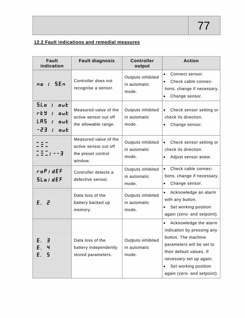
12.2 Fault indications and remedial measures
Fault indication
Fault diagnosis Controller output
Action
/Controller does not
recognise a sensor.
Outputs inhibited
in automatic
mode.
• Connect sensor.
• Check cable connec-
tions, change if necessary.
• Change sensor.
/
/
/
/
Measured value of the
active sensor out off
the allowable range.
Outputs inhibited
in automatic
mode.
• Check sensor setting or
check its direction.
• Change sensor.
/
Measured value of the
active sensor out off
the preset control
window.
Outputs inhibited
in automatic
mode.
• Check sensor setting or
check its direction.
• Adjust sensor anew.
/
/
Controller detects a
defective sensor.
Outputs inhibited
in automatic
mode.
• Check cable connec-
tions, change if necessary.
• Change sensor.
Data loss of the
battery backed up
memory.
Outputs inhibited
in automatic
mode.
• Acknowledge an alarm
with any button.
• Set working position
again (zero- and setpoint).
Data loss of the
battery independently
stored parameters.
Outputs inhibited
in automatic
mode.
• Acknowledge the alarm
indication by pressing any
button. The machine
parameters will be set to
their default values. If
necessary set up again.
• Set working position
again (zero- and setpoint).

78 13. Technical data
On the following pages, you will find several data sheets for the most important
components of this system.
Apart from a dimensional drawing, these data sheets also contain a description of
the interfaces as well as some basic technical data.
The digital controller is availabe in 2 different versions.
The global version (2 appliance plugs in the housing) can be adapted to almost any
machine with an electric tool control. The “pure“ CAN-version (with connector cable
and only one connector plug) has been especially designed for machines which
already have CAN-bus wiring.
The operation of the two controller types is absolutely identical.
As already mentioned in the beginning of these instructions, you can compose your
own individual system which suits the requirements of the respective application.
This means that you may not have acquired one or the other component described
on the following pages.

79
Dimensions:
Technical data: Voltage range: 11V ... 30V (DC) Current consumption: without valves Allowable residual ripple: +/- 10% Power outputs: ON/OFF, PNP/NPN, max. 3A PROP, PNP, max. 2,5A CAN-interface: ISO 11898 - 24 V 125 kBit/sec Ambient temperature range: -10°C ... +70°C Atorage temperature range: -25°C ... +85°C Enclosure protection: IP 67 Weight: ca. 2,2kg
Pin connection:
Power interface 12-pin plug, bayonet type jack A = Input “remote auto/manual B = CAN- C = CAN+ D = Input “machine side recognition“ E = Input “Grade/Slope select“ F = Output “alarm“ G = n.c. H = n.c. J = Output “down“ K = Output “up“ L = +Supply voltage M = -Supply voltage
Sensor interface 7-socket receptacle; bayonet jack
A = + Supply voltage B = CAN+ C = - Supply voltage E = digital I/O “Address1” F = n.c. G = Shield
B
A
C D
E
F
G
Remark: Global-Version
170
1080 66
Art.Nr.:Typ:Ser. Nr.:
(Artikelnummer)(Bezeichnung)(Seriennummer/Datum)
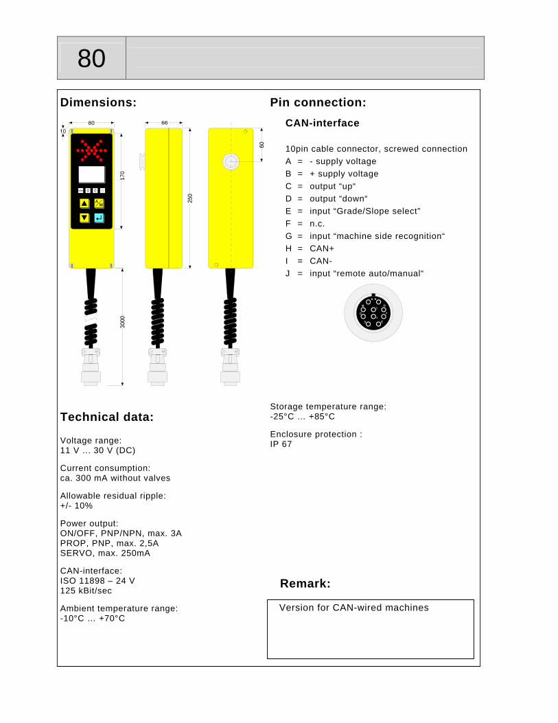
80
Dimensions:
170
Technical data: Voltage range: 11 V ... 30 V (DC) Current consumption: ca. 300 mA without valves Allowable residual ripple: +/- 10% Power output: ON/OFF, PNP/NPN, max. 3A PROP, PNP, max. 2,5A SERVO, max. 250mA CAN-interface: ISO 11898 – 24 V 125 kBit/sec Ambient temperature range: -10°C … +70°C
Pin connection:
CAN-interface 10pin cable connector, screwed connection A = - supply voltage B = + supply voltage C = output “up“ D = output “down“ E = input “Grade/Slope select” F = n.c. G = input “machine side recognition“ H = CAN+ I = CAN- J = input “remote auto/manual“
Storage temperature range: -25°C … +85°C Enclosure protection : IP 67
Remark: Version for CAN-wired machines

81
Switching logic of the 3 inputs of the MOBA-matic:
Input “Grade/Slope change-over”:
Pin E to Ground = Slope sensor
Pin E to +Bat. = Grade sensor
Pin E open (n.c.) = Grade sensor
Input “valve interruption”: *
Pin J to Ground = Stop of automatic
Pin J to +Bat. = Stop of automatic
Pin J open (n.c.) = Automatic free
Input “machine side recognition”:
Pin G to Ground = right
Pin G to +Bat. = left
Pin G open (n.c.) = left
* The logic of the input “valve interruption” can be changed via CAN configuration
message or at the extended parameter menu of the controller.

82
Abmessungen (Dimensions):
126
225250
Technische Daten (Technical data): Betriebsspannung (voltage range): 11V ... 30V (DC) Stromaufnahme (current consumption): max. 50 mA Messbereich (measuring range): +/- 10° Interne Auflösung (internal resolution): 0,01% Nullpunktstabilität (zero point stability): 0,1% Arbeitstemperaturbereich (ambient temperature range): -10°C ... +70°C Lagertemperaturbereich (storage temperature range): -25°C ... +80°C Schutzart (enclosure protection): IP 67 Gewicht (weight): ca. 1,75 kg
100
Pinbelegung (Pin connection): CAN-Schnittstelle (CAN-interface) ISO 11898 - 24V - 125kBit/sec
7pol. Gerätestecker; Bajonettverbindung (7pin connectors; bayonet type connection)
A = + Betriebsspannung (supply voltage) B = CAN+ C = - Betriebsspannung (supply voltage) D = CAN- E = Adr.1 F = Adr.2 G = Schirm (shield) Links (left): E = n.c. F = n.c. Rechts (right): E = - Betriebsspannung (supply voltage) F = n.c.
Bemerkung (Remark):
= neg. Neigung (neg. slope)
= pos. Neigung (pos. slope)

83
Abmessungen (Dimensions):
63,5
280306
152
140
120
Technische Daten (Technical data): Betriebsspannung (voltage range): 11 V ... 30 V (DC) Stromaufnahme (current consumption): Max. 300 mA Zulässige Restwelligkeit (allowable residual ripple): +/- 10% Erfassungsbereich (measuring range) 20cm - 100cm Reproduzierbakeit (reproduceability): +/- 1mm Arbeitstemperaturbereich (ambient temperature range): -10°C ... +70°C Lagertemperaturbereich (storage temperature range): -25°C ... +80°C Schutzart (enclosure protection): IP 67 Gewicht (weight): ca. 2,3 kg
80
Pinbelegung (Pin connection): CAN-Schnittstelle (CAN-interface) ISO 11898 - 24V - 125kBit/sec
7pol. Gerätestecker; Bajonettverbindung (7pin connector; bayonet type connection)
A = + Betriebsspannung (supply voltage) B = CAN+ C = - Betriebsspannung (supply voltage) D = CAN- E = Adr.1 F = Adr.2 G = Schirm (shield)
Bemerkung (Remark):

84
Abmessungen (Dimensions):
B
A C
E
F G
D
262
3210
013
0
76
6584
63
Technische Daten (Technical data): Betriebsspannung (voltage range): 10V ... 30V (DC) Stromaufnahme (current consumption): < 100mA @ 24V < 200mA @ 12V Meßbereich (measuring range): 20cm … 100cm Linearitätsabweichung (linearity deviation): 0,2% vom Endwert (full scale) Offset (offset): ± 1mm Temperaturabweichung im Bereich -25°C ... +85°C (temperature deviation at the range -25°C ... +85°C) max. ± 1% vom Messwert (of reading) Arbeitstemperaturbereich (ambient temperature range): -25°C ... +85°C Lagertemperaturbereich (storage temperature range): -25°C ... +85°C Schutzart (enclosure protection): IP 67
Pinbelegung (Pin connection): CAN-Schnittstelle (CAN-interface) ISO 11898 - 24 V 125 kBit/sec 7pol. Gerätestecker; Bajonettverbindung (7pin connector; bayonet type connection)
A = + Betriebsspannung (supply voltage) B = CAN+ C = - Betriebsspannung (supply voltage) D = CAN- E = Adr. 1 F = Adr. 2 G = Schirm (shield)
B
A
C
E
F
G
D
Bemerkung (Remark):

85
Abmessungen (Dimensions):
15011263,5
Technische Daten (Technical data): Betriebsspannung (voltage range): 11V ... 30V (DC) Stromaufnahme (current consumption): Max. 50mA Zulässige Restwelligkeit (allowable residual ripple): +/- 10% Erfassungsbereich (measuring range): +/- 30° Interne Auflösung (internal resolution): 0,1° Reproduzierbakeit (reproduceability): +/- 0,1° Arbeitstemperaturbereich (ambient temperature range): -10°C ... +70°C Lagertemperaturbereich (storage temperature range): -25°C ... +80°C Schutzart (enclosure protection): IP 67 Gewicht (weight): Ca. 1,1Kg
106,592
63,5
9
91 784
Pinbelegung (Pin connection):
CAN-Schnittstelle (CAN interface) ISO 11898 - 24V; 125 kBits/sec
7pol. Verbinder; Bajonettverbindung (7pin connector; bayonet type connection)
A = + Betriebsspannung (supply voltage) B = CAN+ C = - Betriebsspannung (supply voltage) D = CAN- E = Adr.1 F = Adr.2 G = Schirm (shield)
Bemerkung (Remark):

86
Abmessungen (Dimensions):
125 mm
150 mm
100
mm
125
mm
d = 8,5 mm
Technische Daten (Technical data): Betriebsspannung (voltage range): 10 V ... 30 V (DC) Stromaufnahme (current consumption): < 200 mA Messbereich (measuring range): 50 cm CAN-Schnittstelle (CAN-interface): ISO 11898 - 24 V; 125 kBit/sec.; Arbeitstemperaturbereich (ambient temperature range): -10°C ... +60°C Lagertemperaturbereich (storage temperature range): -25°C ... +75°C Schutzart (enclosure protection): IP 54 Gewicht (weight): ca. 1,75 kg
100 mm
5 m
m
62 m
m
152 mm
Pinbelegung (Pin connection):
7pol. Gerätestecker; Bajonettverbindung (7pin plug; bayonet type connection) A = + Betriebsspannung (supply voltage) B = CAN + C = - Betriebsspannung (supply voltage) D = CAN - E = Adresse1 (address1) F = Adresse2 (address2) G = Schirm (shield)
Bemerkung (Remark):
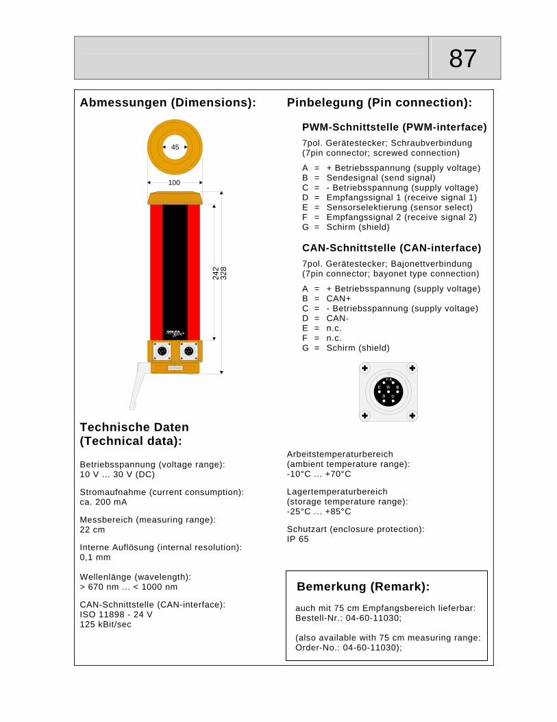
87
Abmessungen (Dimensions):
45
100
242
328
Technische Daten (Technical data): Betriebsspannung (voltage range): 10 V ... 30 V (DC) Stromaufnahme (current consumption): ca. 200 mA Messbereich (measuring range): 22 cm Interne Auflösung (internal resolution): 0,1 mm Wellenlänge (wavelength): > 670 nm ... < 1000 nm CAN-Schnittstelle (CAN-interface): ISO 11898 - 24 V 125 kBit/sec
Pinbelegung (Pin connection): PWM-Schnittstelle (PWM-interface) 7pol. Gerätestecker; Schraubverbindung (7pin connector; screwed connection)
A = + Betriebsspannung (supply voltage) B = Sendesignal (send signal) C = - Betriebsspannung (supply voltage) D = Empfangssignal 1 (receive signal 1) E = Sensorselektierung (sensor select) F = Empfangssignal 2 (receive signal 2) G = Schirm (shield) CAN-Schnittstelle (CAN-interface) 7pol. Gerätestecker; Bajonettverbindung (7pin connector; bayonet type connection)
A = + Betriebsspannung (supply voltage) B = CAN+ C = - Betriebsspannung (supply voltage) D = CAN- E = n.c. F = n.c. G = Schirm (shield)
Arbeitstemperaturbereich (ambient temperature range): -10°C ... +70°C Lagertemperaturbereich (storage temperature range): -25°C ... +85°C Schutzart (enclosure protection): IP 65
Bemerkung (Remark): auch mit 75 cm Empfangsbereich lieferbar: Bestell-Nr.: 04-60-11030; (also available with 75 cm measuring range: Order-No.: 04-60-11030);

88 14. Parameter menu
14.1 General information
All parameters have been factory preset to default values at the house of MOBA.
With these defaults a sufficient operation of the most usual types of machines is
ensured. Nevertheless it is recommended to optimize each system by adjusting its
parameters depending on the specific conditions of the machine.
The parameter settings can be done in manual mode as well as in automatic mode.
So the user has got the possibility to optimize his system while working.
If any button is pressed while the starting message is indicated, the software version
appears on the display for about 4 seconds.
In this manual we will not separately deal with the working menu of the MOBA-
matic. For informations and instructions concerning the working menu please see
the operating instruction.
Switch on voltage supply
Data recordfaulty?
Error message e.g. "E.2"
Startingmessage
"1888"
Version / Identifier"4.28 / 00X"
yes
no
Sensor messagez.B. “rop / SEn"
Working menu
1 sec. 4 sec.
2 sec.

89
14.2 Operator menu
14.2.1 Operator menu access
The operator menu can be accessed from the working menu only.
To access the first parameter press the A/M button
and the ENTER buttons at the same time.
Use this button combination to switch from one
parameter to the next.
By pressing the UP button or the DOWN button
parameter values are set or function modes are
changed.
The operator menu can be exited any time by
pressing the A/M button.
T5 sec.
If no button is pressed for about 5 seconds the
controller automatically switches back to the working
menu.

90 14.2.2 Operator menu diagram
Working menu
Operator menu
5 sec.
Ext.3D set-pointassignment?
3D set-point assignment"SP / A "
Sensitivity mode SE = OFF?
Deadband"db / 0.2 or 0.04"
Sensitivity"SE / 6"
Control window" / OFF"
Unit of distance"CAL / CEn"
Hydraulic record"tYP / X"
yes
(1 - 10 or1.0 - 10.0 with Prop and Servo)
(2.0cm - 20.0cm / OFF or 0.8inch - 8.0inch / OFF or 0.06Ft - 0.66Ft / OFF)
(CEn / inch / Ft)
(1 - set limit)
(SLo / LAS / rop / rtY / Son / / 123 / 1-3 / 3d)
yes
Grade sensor selected? yes
Several sensors connected?
Sensor selection"S-S / e.g. rop"
yes
Grade selected & Slope
connected?
Indication of cross slope"SLo / e.g. 1.20"
yes
Propband"Pb / 1.0 or 1.0"
(Hd / A)
(0.0cm - 4.0cm with Grade or 0.00% - 4.00% with Slope )
(0.0cm - 40.0cm with Grade or 0.0% - 40.0% with Slope )
Positionfactor Po.S = on
& no 3D?
Position factor"PoS / 1.00"
yes
(0.60 - 1.50)

91
14.2.3 Operator menu description of parameters
Parameter Sign Default Range Description
Indication of cross slope
Measuring range of the cross slope sensor
If a slope sensor is connected to the CAN bus and a grade sensor is selected as active sensor for the controller, the actual measured slope of the tool is indicated here.
Sensor selection
, , , , , ,
, etc.
Parameter appears only if more than one MOBA-matic sensor is connected to the CAN bus. In this case the selection of the active sensor is done here. For the meaning of the abbreviations please see the MOBA-matic operating instructions.
3D set-point assignment
or ; If the controller receives external 3D set-point assignments you can choose whether this shall be used for the controlling or whether the controlling is to be made via manual inputs at the push buttons of the controller.
= automatic = controlling; = manual mode = Controlling is made
via push button inputs;
Sensitivity or
with Prop and Servo valves;
Sensor sensitivity adjustment. An increase of this value means that the controlling happens faster and it is tried to get a closer result to the adjusted setpoint.
Deadband or
cm for grade sensors;
% for slope sensors;
Range around the operating point in which no valve drive is done. Comparable with an accuracy tolerance.
Propband or
cm for grade sensors;
% for slope sensors;
Range above and underneath the Deadband where a defined valve drive, depending on the deviation to the operating point, is done. The shortest pulse is set as Min. pulse or Min. current, the longest one is made up of Min. pulse + Delta max. pulse or is set as Max. current. The pulse-times between Min. and Max. are interpolated over the range of the Propband.
Control window
OFF cm;
inch;
Ft; or ;
The automatic control of the valves is switched off and the sign of the control window is indicated, if a deviation appears that is bigger than the value set here.
This parameter can be deactivated by increasing the value until „OFF“ is indicated.

92
Parameter Signl Default Range Description
Unit of distance or
Physical unit for all distance measurements: = Centimeter;
= Inch; = Feet;
Position factor If the change of height at a sensor is unequal to the change of height of the tool of the machine which is to be controlled then the position factor can make the changes equal.
Hydraulic record
– set limit (see also „Limit hydraulic type“ at the extended para-meter menu);
Settings for different machines can be stored under the positions 1 to X, in case that the controller is used on several machines with hydraulic actions that differ from each other.
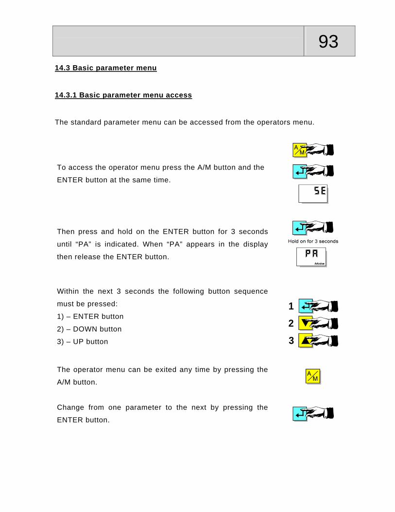
93
14.3 Basic parameter menu
14.3.1 Basic parameter menu access
The standard parameter menu can be accessed from the operators menu.
To access the operator menu press the A/M button and the
ENTER button at the same time.
Then press and hold on the ENTER button for 3 seconds
until “PA” is indicated. When “PA” appears in the display
then release the ENTER button.
Within the next 3 seconds the following button sequence
must be pressed:
1) – ENTER button
2) – DOWN button
3) – UP button
123
The operator menu can be exited any time by pressing the
A/M button.
Change from one parameter to the next by pressing the
ENTER button.
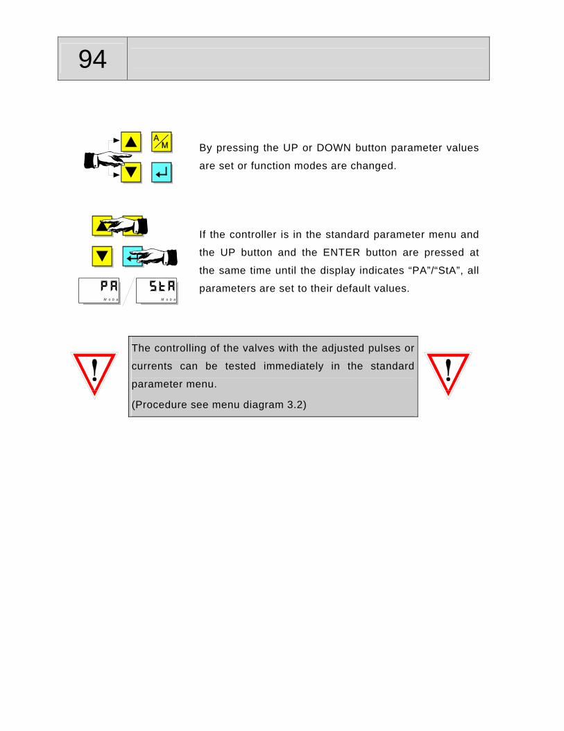
94
By pressing the UP or DOWN button parameter values
are set or function modes are changed.
M o b a M o b a
If the controller is in the standard parameter menu and
the UP button and the ENTER button are pressed at
the same time until the display indicates “PA”/“StA”, all
parameters are set to their default values.
The controlling of the valves with the adjusted pulses or
currents can be tested immediately in the standard
parameter menu.
(Procedure see menu diagram 3.2)
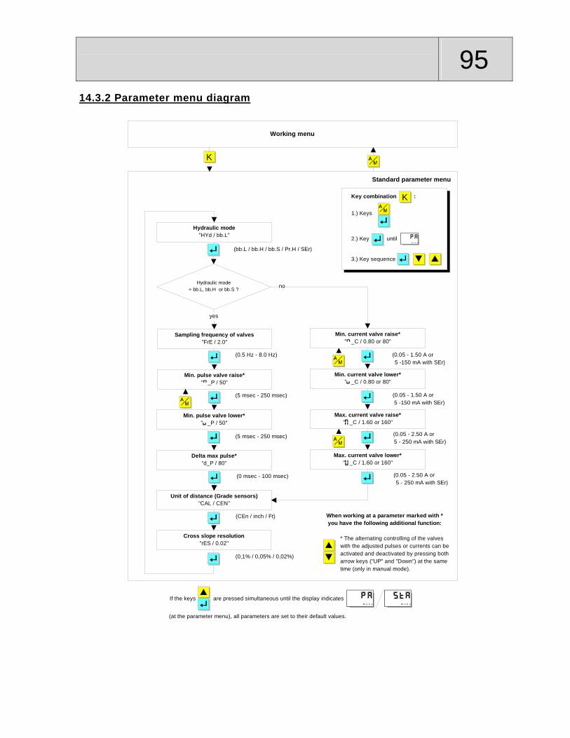
95
14.3.2 Parameter menu diagram
Working menu
Hydraulic mode"HYd / bb.L"
Sampling frequency of valves"FrE / 2.0"
Min. pulse valve raise*" _P / 50"
Min. pulse valve lower*" _P / 50"
Min. current valve raise*" _C / 0.80 or 80"
Min. current valve lower*" _C / 0.80 or 80"
Max. current valve raise*" _C / 1.60 or 160"
Max. current valve lower*" _C / 1.60 or 160"
Hydraulic mode= bb.L, bb.H or bb.S ? no
yes
(bb.L / bb.H / bb.S / Pr.H / SEr)
(0.5 Hz - 8.0 Hz)
(5 msec - 250 msec) (0.05 - 1.50 A or 5 -150 mA with SEr)
(0.05 - 1.50 A or 5 -150 mA with SEr)
(0.05 - 2.50 A or 5 - 250 mA with SEr)
(0.05 - 2.50 A or 5 - 250 mA with SEr)
K
Standard parameter menu
Key combination : K
1.) Keys
2.) Key until M o b a
3.) Key sequence
If the keys are pressed simultaneous until the display indicatesM o b a M o b a
(at the parameter menu), all parameters are set to their default values.
* The alternating controlling of the valveswith the adjusted pulses or currents can beactivated and deactivated by pressing botharrow keys ("UP" and "Down") at the sametime (only in manual mode).
When working at a parameter marked with *you have the following additional function:
(5 msec - 250 msec)
(0,1% / 0,05% / 0,02%)
(CEn / inch / Ft)
Unit of distance (Grade sensors)"CAL / CEN"
Cross slope resolution"rES / 0.02"
Delta max pulse*"d_P / 80"
(0 msec - 100 msec)

96 14.3.3 Basic menu description of parameters
Parameter Sign Default Range Description
Hydraulic Mode ,,,
or
Type and drive technique of the valves:
= On/Off valve, minus switching = On/Off valve, plus switching = Servo valve in switching mode = Prop. valves, plus switching
= Servo valves
Sampling frequency of valves
Parameter for On/Off valves and servo valves in switching mode only Frequency for the valve drive within Propband.
Min. pulse of valve raise
Parameter for On/Off valves and servo valves in switching mode only Shortest time that is to be used for the drive of the valve raise, when the deviation is within Propband = defines the lowest possiblecylinder speed.
Min. pulse of valve lower
Parameter for On/Off valves and servo valves in switching mode only Shortest time that is to be used for the drive of the valve lower, when the deviation is within Propband = defines the lowest possible cylinder speed.
Delta max pulse
Parameter for On/Off valves and servo valves in switching mode only The sum of Min. pulse raise or lower and the time that is set here results in the Max. pulse (highest allowed cylinder speed) for the valve drive within Propband. The pulse-times between Min. and Max. are interpolated over the range of the Propband.
Min. current of valve raise
or with
Servo
to or to with Servo;
Parameter for proportional valves and servo valves only. Lowest current that is to be used for the drive of the valve raise = defines the lowest possible cylinder speed.
Min. current of valve lower
or with
Servo
to or to with Servo;
Parameter for proportional valves and servo valves only. Lowest current that is to be used for the drive of the valve lower = defines the lowest possible cylinder speed.
Max. current of valve raise
or with
Servo
or
with Servo;
Parameter for proportional valves and servo valves only. Highest current that is to be used for the drive of the valve raise = defines the highest allowed cylinder speed.

97
Parameter Sign Default Range Description
Max. current of valve lower
or with
Servo
or
with Servo;
Parameter for proportional valves and servo valves only. Highest current that is to be used for the drive of the valve lower = defines the highest allowed cylinder speed.
Unit of distance , or
Physical unit for all distance measurements: = Centimeter;
= Inch; = Feet;
Cross slope resolution
, or Displayed resolution of the cross slope:
= 1/10%;
= 5/100%;
= 2/100%;

98 14.4 Extended parameter menu
14.4.1 Extended parameter menu access
The extended parameter menu can be accessed from the working menu only.
Access the operator menu by pressing the A/M button
and the ENTER button at the same time.
Hold on the ENTER button for 3 seconds until “PA” is
indicated.
123
Within the next 3 seconds the button sequence:
1) - ENTER button
2) - DOWN button
3) - UP button
has to be pressed.
Now hold the ENTER button pressed for about 5 seconds
until “SES” appears in the display.

99
The operator menu can be left any time by pressing the
A/M button.
To change from one parameter to the next press the
ENTER button.
By pressing the UP button or the DOWN button parameter
values are set or function modes are changed.
If the controller is in the extended parameter menu and
the UP button and the ENTER button are pressed at the
same time until the display indicates “PA”/“StA”, all
parameters are set to their default values. M o b a M o b a
The controlling of the valves with the adjusted pulses
or currents can be tested immediately in the
extended parameter menu.
(Procedure see menu diagram 4.2)
If the sensitivity mode is deactivated in the extended
parameter menu, the operator menu changes.
(See sections 2.2 and 2.3 of these instructions)

100 14.4.2 Extended paramater menu diagram
Working menu
Sensitivity mode SE "SE.S / on"
Limit hydraulic type "tY.L / 6"
Sampling frequency of valves"FrE / 2.0"
Min. pulse valve raise*" _P / 50"
Min. pulse valve lower*" _P / 50"
Min. current valve raise*" _C / 0.80 or 80"
Min. current valve lower*" _C / 0.80 or 80"
Max. current valve raise*" _C / 1.60 or 160"
Max. current valve lower*" _C / 1.60 or 160"
Hydraulic mode= bb.L, bb.H or bb.S ?
yes
(on / OFF)
(1.0 Hz - 8.0 Hz)
(5 msec - 250 msec) (0.05 - 1.50 A or 5 -150 mA with SEr)
(0.05 - 1.50 A or 5 -150 mA with SEr)
(0.05 - 2.50 A or 5 - 250 mA with SEr)
(0.05 - 2.50 A or 5 - 250 mA with SEr)
Extended parameter menu
(5 msec - 250 msec)
Delta max pulse*"d_P / 80"
(0 msec - 100 msec)
no
User mode "USE / StA"
(StA / H_A / A_0)
Hydraulic mode "HYd / bb.L"
(bb.L / bb.H / bb.S / Pr.H / SEr)
(1 - 40)
Activation position factor "Po.S / OFF"
(on / OFF)
K
BAC
ExternStopAuto "ESA / H_L"
(H_L / n.c.)
Key combination : K
1.) Keys
2.) Key until M o b a
3.) Key sequence
4.) Key for at least 5 sec.

101
Max. pulse valve raise or lower =Min. pulse valve raise or lower + Delta max pulse
Low-pass filter limit frequency"FGF / 1.0"
Cycle time CAN-Message"CYC / 0,50"
(0,1% / 0,05% / 0,02%)
Cross slope resolution"rES / 0.02"
CAN-Ski Adressmode"S.Ad / 8"
(8 / 4)
(OFF / 0,4 Hz - 15,0 Hz)
Stored with every CAN-sensor, but editable.
Sensor identifier**"Son / "
(0,01 sec - 10,0 sec / OFF)
(CEn / inch / Ft)
Unit of distance (Grade sensors)"CAL / CEn"
Max. permissible current valve raise" .HC / 2.50 or 250"
Max. permissible current valve lower" .HC / 2.50 or 250"
Hydraulikmode= bb.H or bb.S ?
yes
(0.05 - 2.50 A or 5 - 250 mA with SEr)
(0.05 - 2.50 A or 5 - 250 mA with SEr)
BAC
no

102 If you are working at a parameter marked with * or ** you have the following addi-
tional functions:
* = By pressing both arrow buttons (“Up” and “Down”) at the same time the
alternating controlling of the valves with the adjusted pulses or currents can be
activated and deactivated (only in manual mode).
** = By pressing the Up-button and the Down-button the measured value of each
sensorhead of the Sonic-Ski sensor will be indicated separately. These values are
without compensation of running time and correspond to 1 mm.

103
14.4.3 Extended menu description of parameters
Parameter Sign Default Range Description
Sensitivity SE SES on on or OFF; Select “SE” (Sensitivity) or “DB” (Deadband); “PB” (Proportional Band) for adjustment from the operators menu
on = Sensitivity setting from prestored values;
OFF = Deadband and Propband can be set directly - operator menu has changed.
User mode USE StA StA, H_A or A_O;
The operator has the opportunity to choose from 3 different variants of operation (see also the operation instructions): StA = Operating modes Manual & Automatic; set-point adjustment takes place in 1mm steps (with quick adjustment); when changing the set-point the new numerical value is indi-cated at the display; H_A = Divergent to StA there is additional the operating mode half automatic (set-point ad-justment takes place with deactivated con-troller outputs);
A_0 = Divergent to StA the set-point adjust-ment takes place in 2mm steps (every time the button is pressed anew); when changing the set-point the new adjusted numerical value is automatically taken over as zero point, and indicated „0.0“ at the display, after about 5 seconds;
Activation position factor
Po.S OFF on or OFF; Enables the “position factor” to be accessed from the operators menu.
on = Position factor can be set;
OFF = Position factor can not be set
ExternStopAuto ESA H_L H_L or n.c. Sets the voltage level that has to be fed to pin J of the connection plug to stop the “Auto”-function of the controller (emergency switch).
H_L = StopAuto with high or low level;
n.c. = StopAuto with pin J open (high-resis-tance input);
Limit Hydraulic type
tY.L 6 1 - 40 Sets the maximum number of programmable and selectable hydraulic records (see operator menu).

104
Parameter Sign Default Range Description
Hydraulic mode
HYd bb.L bb.L, bb.H, bb.S, Pr.H or SEr;
Type and drive technique of the connected valves:
bb.L = On/Off valve, minus switching bb.H = On/Off valve, plus switching bb.S = Servo valve in switching mode Pr.H = Prop. valves, plus switching SEr = Servo valves
Sampling frequency of valves
FrE 2.0 0.5 - 8.0Hz; Parameter for On/Off valves and servo valves in switching mode only Frequency for the valve drive within Propband.
Min. pulse of valve raise
_P 50 5 - 250msec; Parameter for On/Off valves and servo valves in switching mode only Shortest time that is to be used for the drive of the valve raise, when the deviation is within Propband = defines the lowest possible cylinder speed.
Min. pulse of valve lower
_P 50 5 - 250msec; Parameter for On/Off valves and servo valves in switching mode only Shortest time that is to be used for the drive of the valve lower, when the deviation is within Propband = defines the lowest possible cylinder speed.
Delta max pulse
d_P 80 0 - 100msec Parameter for On/Off valves and servo valves in switching mode only The sum of Min. pulse raise or lower and the time that is set here results in the Max. pulse (highest allowed cylinder speed) for the valve drive within Propband. The pulse-times between Min. and Max. are interpolated over the range of the Propband.
Min. current of valve raise
_C 0.80 or 80 with Servo
0.05 - 1.50A; or 5 - 150mA with Servo;
Parameter for proportional valves and servo valves only. Lowest current that is to be used for the drive of the valve raise = defines the lowest possible cylinder speed.
Min. current of valve lower
_C 0.80 or 80 with Servo
0.05 - 1.50A; or 5 - 150mA with Servo;
Parameter for proportional valves and servo valves only. Lowest current that is to be used for the drive of the valve lower = defines the lowest possible cylinder speed.
Max. current of valve raise
_C 1.60 or 160 with Servo
0.05 - 2.50A; or 5 - 250mA with Servo;
Parameter for proportional valves and servo valves only. Highest current that is to be used for the drive of the valve raise = defines the highest allowed cylinder speed.
Max. current of valve lower
_C 1.60 or 160 with Servo
0.05 - 2.50A; or 5 - 250mA with Servo;
Parameter for proportional valves and servo valves only. Highest current that is to be used for the drive of the valve lower = defines the highest allowed cylinder speed.

105
Parameter Sign Default Range Description
Parameter Sign Default Range Description
Max. permissible current of valve raise
.HC 2.50 or 250 with Servo
0.05 - 2.50A; or
5 - 250mA with
Servo;
Parameter for On/Off valves (plus switching) and Servo valves in switching mode only. Highest permissible current that may flow during the drive of the valve raise.
Max. permissible current of valve lower
.HC 2.50 or 250 with Servo
0.05 - 2.50A; or
5 - 250mA with
Servo;
Parameter for On/Off valves (plus switching) and Servo valves in switching mode only. Highest permissible current that may flow during the drive of the valve lower.
Unit of distance
CAL CEn CEn, inch or Ft; Physical unit for all distance mea-surements: CEn = Centimeter;
inch = Inch;
Ft = Feet; Slope resolution
rES 0.02 0.1, 0.05 or
0.02; Displayed resolution of the cross slope: 0.1 = 1/10%
0.05 = 5/100%
0.02 = 2/100% Low-pass filter limit frequency
FGF 1.0 0.4 - 15.0Hz or
OFF Low-pass filter of 2nd order; Value is stored in each CAN sensor. Can be edited.
CAN-Ski Adressmode
S.Ad 8 8 or 4; 8 (new adressing) = 2 MOBA-matic controllers with 4 sensors each can operate in one CAN-network; 4 (old adressing) = only in order to ensure the downward compatibility to old Ski models and old Big-Ski junctionboxes.
Cycle time CAN-Message
CYC 0,10 0.01 – 10.0sec
or OFF
Time interval that is used by the MOBA-matic
to send the control-relevant parameters
(Actual value, setpoint etc.) onto the CAN-
bus.
Sensor identifier
The current connected type of sensor is detected. If the Sonic-Ski sensor is connected the distance of each sensorhead can be checked separately.

106 15. Controller set up examples 15.1 Steps to program a controller for a paver
Program the correct hydraulic type for your machine and make sure that depressing
the up arrow on the controller will move the cylinder up and depressing the down
arrow will move the cylinder down.
Note. If the Tow Point Cylinder will not move then take the following steps:
The default value of the controller for the valve current may need to be increased for
the tow-point to move.
Make sure that there is not a cylinder shut off that is closed.
Double-check the Hydraulic setting of the controller to match the machine.
Note. If your machines raise and lower are backward then take the following step:
By swapping the connectors at the valve you will change the raise and lower.
With the above steps complete and you can raise and lower the Tow-Point Cylinder
you can now start to program the valve speeds of the machine.

107
Steps to setting Valve Speeds:
1.Enter the Technicians menu of the controller and go to the Min Up value. Refer to
page two for this proceedure.
The standard parameter menu can be called up from the working menu only.
Therefore:
First switch over to the operator menu by pressing the A/M
key and the ENTER key at the same time.
Hold on the ENTER key for 3 seconds until „PA“ is
indicated.
Within the next 3 seconds the key sequence: 1) – ENTER key 2) – DOWN key 3) – UP key has to be pressed.
123
Note. After step 3 is complete you will see HYD in the Display. By depressing the blue button you will go to the Min Up symbol. ( ) Min UP Current ( ) Min DOWN Current ( ) Max UP Current ( ) Max DOWN Current
108 2. With the Min Up value in the display, lower this down to its lowest number. Then depress the blue button once and it will go to the Min Down value and lower this number as well. After this is complete depress the A/M button until you are at the working display. 3. Lower the Screed and set it on a pipe that is going perpindicular with the machine.this pipe should be no smaller than 1.5“. By doing this step you have now made the screed so that it will pivot on the pipe and not be bound up at any point on the ground. 4. Connect a grade sensor to the end-gate or tow-arm, center the towpoint and set your sensor hieght to 14“. 5. Zero your sensor by depressing the Blue button on the controller and the display should read 0.0 6. Put the controller in automatic by depressing the A/M button. At this time you should have 0.0 in the display and the Automatic light should be illuminated. 7. Depress the up arrow two times until the display reads 0.2. At this time you should have a flashing up arrow with the tow-point cylinder Not Moving Up. 8. While the controller is in Automatic, enter the Technicians menu and go to the Min up value and raise the number slowly until the machine goes to grade.
a. At this time you should still have Min Up in the display and you can now depress the Blue button and go to the Min Down value.
9. By using the manual switch for the tow-point cylinder, just bump the switch to make the cylinder go up and the Controller will flash a down arrow. 10. Increase the Min Down value slowly until the machine moves to grade and stops. 11. Jog the manual switch up and it should come to grade. Jog the manual switch down and the machine should come to grade. If it still flashes a little then just increase the current value one or two until it goes to grade and repeat this step. Adjusting the Max Up and Max Down. Note. For Machines with On / Off Valves you will not have Max Up or Max Down you will however find in the bottom menu a setting for Delta Pulse or ( dp ).
a. Delta pulse is a combined number for max up and max down. b. The number that is displayed can be lowered to slow the large correction or raised
to speed up a large responce. c. The default value of 80 is generaly fine for most applications. d. At this point your machine should be set-up and you can check the responce by
dialing the controller up 1.5“ and then down 1.5“ . Your tow-point should go to grade and stop without any Over Shooting.
e. After checking the responce set–up is complete and you should proceed to step 14.

109
Note. For machines with Proportional valves a good starting point for Max Current is to add 20 - 30 to the Min current for example, if you have a Min Up value of 20 then you would set your Max UP to 40 - 50. After confirming steps 3,4,5 and 6 proceed to the next step. 12. With the down arrow on the controller depressed, take the value down to –1.5“ and the tow-point should go down and stop.
a. If it is too slow, go to the Technicians Menu, refer to the Max Down value and add another 5 to 10 and repeat until its the speed you want.
b. If it is too fast then drop your numbers another 5 to 10 and repeat the step. c. Once the Down side is good, proceed to 13.
13. With the Up arrow on the controller depressed, take the value down to 1.5“ and the tow-point should go UP and stop.
a. If it is too slow, go to the Technicians Menu, refer to the Max Up value and add another 5 to 10 and repeat until its the speed you want.
b. If it is too fast then drop your numbers another 5 to 10 and repeat the step. c. Once the Up side is good, proceed to the next step.
14. With the above steps complete you are ready to get the machine on the road. A great help in knowing that you have tuned this machine correctly is watching the lights on the controller while your paving.
a. You should see the On Grade Symbol most of the time with a flashing up or down arrow from time to time.
b. If you see a lot of flashing in one direction or both then leave it in Automatic, go to the Technicians menu and adjust your Min up or Min down 1 – 2 and see if this helps.
c. After your changes depress the A/M button and return to the working display keeping in mind that the Automatic light should still be illuminated.

110 15.2 Steps to progam a controller for a mill Program the correct hydraulic type for your machine and make sure that depressing
the up arrow on the controller will move the machine up and depressing the down
arrow will move the machine down.
Note. If the tow point cylinder will not move or the raise and lower are backward
then take the following steps:
The default value of the controller for the valve current may need to be increased for
the machine to move.
Make sure that there is not a cylinder shut off that is closed.
Double-check the Hydraulic setting of the controller to match the machine.
Note. If your machines raise and lower are backward then take the following step:
By swapping the connectors at the valve you will change the raise and lower.
With the above steps complete and you can raise and lower the machine you can
now start to program the valve speeds of the machine.

111
Steps to setting Valve Speeds:
1.Enter the Technicians menu of the controller and go to the Min Up value. Refer to
page two for this proceedure.
The standard parameter menu can be called up from the working menu only.
Therefore:
First switch over to the operator menu by pressing the A/M
key and the ENTER key at the same time.
Hold on the ENTER key for 3 seconds until „PA“ is
indicated.
Within the next 3 seconds the key sequence: 1) – ENTER key 2) – DOWN key 3) – UP key has to be pressed.
123
Note. After step 3 is complete you will see HYD in the Display. By depressing the blue button you will go to the Min Up symbol. ( ) Min UP Current ( ) Min DOWN Current ( ) Max UP Current
( ) Max DOWN Current

112 2. With the Min Up value in the display, lower this down to its lowest number. Then depress the blue button once and it will go to the Min Down value and lower this number as well. After this is complete depress the A/M button until you are at the working display. 3. Lower the machine so that the Drum is about 3” off the ground, even across and your end gate is flat on the ground. Note. In some cases your End Gate may not touch the ground with the machine 3“ off the ground. By blocking the End Gate this will give you the offset that you need. 4. Connect a grade sensor and for this exercise we will pick the wire rope. 5. Zero your sensor by depressing the Blue button on the controller and the display should read 0.0 6. Put the controller in automatic by depressing the A/M button. At this time you should have 0.0 in the display and the Automatic light should be illuminated. 7. Depress the up arrow two times until the display reads 0.2. At this time you should have a flashing up arrow with the machine Not Moving Up. 8. While the controller is in automatic, enter the Technicians menu and go to the Min up value and raise the number slowly until the machine goes to grade.
b. At this time you should still have Min Up in the display and you can now depress the Blue button and go to the Min Down value.
9. By using the manual switch for the front leg, just bump the switch to make the machine go up and the Controller will flash a down arrow. 10. Increase the Min Down value slowly until the machine moves to grade and stops. 11. Jog the manual switch up and it should come to grade. Jog the manual switch down and the machine should come to grade. If it still flashes a little then just increase the value one or two until it goes to grade and repeat this step. Adjusting the Max Up and Max Down. For a good starting point for Max Current Speed add 10-15 to the Min current for example, if you have a Min Up value of 20 then you would set your Max UP to 30 - 35. After confirming steps 3,4,5 and 6 proceed to the next step. 12. With the Manual switch drop the machine down about 1.5” to 2” and watch the speed of the machine.
d. If it is too slow then leave the controller in automatic and go to the Technicians Menu, refer to the Max Up value and add another 5 to 10. Stay in the Max Up and repeat step 12.

113
Note. If it is too fast then drop your numbers another 5 to 10.
e. Once you are getting close to the speed that you want drop down to steps of 5 until you like what you see and there is No Over Shooting.
f. Your Machine should start moving as soon as the manual switch is released. The machine should Accelerate up, then start Decelerating to grade and stop at the On Grade Symbol.
g. Once the up side is good, go to the Max Down by depressing the Blue button and proceed to 13.
13. With the Manual switch raise the machine Up about 1.5” to 2” and watch the speed of the machine.
d. If it is too slow then leave the controller in automatic and go to the Technicians Menu, refer to the Max Down value and add another 5 to 10. Stay in the Max Down and repeat step 13.
e. Once you are getting close to the speed that you want, drop down to steps of 5 until you like what you see and there is No Over Shooting.
f. Your Machine should start moving as soon as the manual switch is released.
The machine should Accelerate Down, then start Decelerating to grade and stop at the On Grade Symbol.
g. Once the Down side is good, depress the A/M button until you return to the working display.
14. With the above steps complete you are ready to get the machine in the cut. A great help in knowing that you have tuned this machine correctly is watching the lights on the controller while the machine is cutting.
d. You should see the On Grade Symbol most of the time with a flashing up or down arrow.
h. If you see a lot of flashing in one direction or both then leave it in Automatic, go
to the Technicians menu and adjust your Min up or Min down 1 – 2 and see if this helps.
i. After your changes depress the A/M button and return to the working display keeping in mind that the Automatic light should still be illuminated.

114
KONFORMITÄTSERKLÄRUNG Entsprechend ISO/EC Guide 22 und EN 45014
Name des Herstellers: MOBA Mobile Automation
Anschrift des Herstellers: MOBA Mobile Automation Vor den Eichen 4 D-65604 Elz
Der Hersteller erklärt, dass die Produkte:
Produktname: MOBA-matic System Modell-Nr. der im System getesteten Geräte: Digitaler Regler 04-25-10443 und 453 Digi Slope Sensor 04-21-21010 Sonic-Ski 04-21-10020 Rotary Sensor 04-21-40110 Seilzugsensor 04-21-30020 Laserempfänger LS-250 04-60-11010
den folgenden Produktspezifikationen entspricht:
Sicherheit: DIN VDE 411, Teil 1, 0001/10.73
EMV (EMC): EN 55011 - DIN VDE 0875 T11 (1992), Grenzwertklasse B ENV 50140 - DIN VDE 847 T3 (1993) Kriterium A ENV 50140 - DIN VDE 847 (1993), IEC 65A/77B (Sec) 145/110 Kriterium A EN61000-4-2 (1995), IEC 1000-4-2 (1995), VDE0847 Teil 4-2 Kriterium B ENV50141 (1993), E IEC 1000-4-6, E DIN VDE 0843 T6:12/93 EN61000-4-4:1995, IEC 1000-4-4:1995, VDE 0847 Teil 4-4 Kriterium B
Kriterien nach EN 50082 T/2
Zusätzliche Informationen:
Das Produkt entspricht den Anforderungen der EMV-Verordnung 89/336/EWG. Es wurde ineiner typischen Konfiguration getestet. Die Inbetriebnahme der Komponenten ist solangeuntersagt, bis festgestellt wurde, dass die Maschine, in die dieses Produkt eingebaut werdensoll, den Bestimmungen der EG-Richtlinie entspricht.
Elz, den 04 Juli 2002 Dipl.-Ing. Markus Wendel Qualitäts-Management-Beauftragter
16. Declaration of conformance


