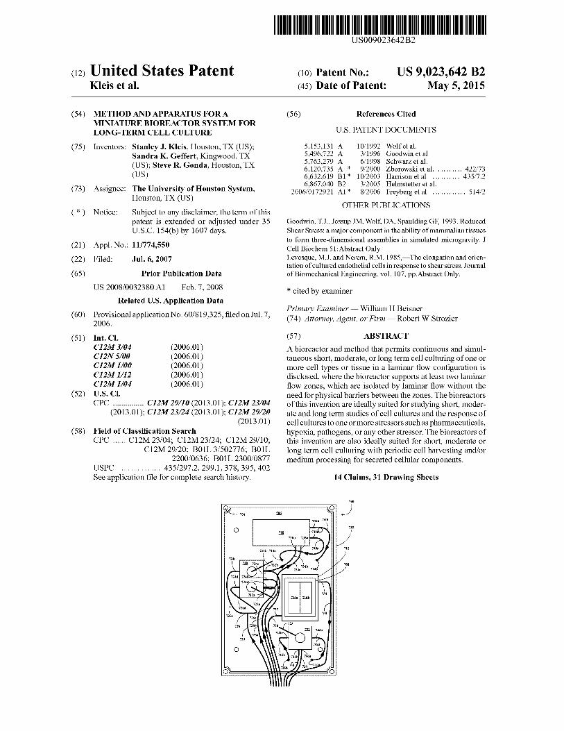
1111111111111111111111111111111111111111111111111111111111111111111111111111 (12) United States Patent Kleis et al. (54) METHOD AND APPARATUS FOR A MINIATURE BIOREACTOR SYSTEM FOR LONG-TERM CELL CULTURE (75) Inventors: Stanley J. Kleis, Houston, TX (US); Sandra K. Geffert, Kingwood, TX (US); Steve R. Gonda, Houston, TX (US) (73) Assignee: The University of Houston System, Houston, TX (US) (*) Notice: Subject to any disclaimer, the term of this patent is extended or adjusted under 35 U.S.C. 154(b) by 1607 days. (21) Appl. No.: 11/774,550 (22) Filed: Jul. 6, 2007 (65) Prior Publication Data US 2008/0032380 Al Feb. 7, 2008 Related U.S. Application Data (60) Provisional application No. 60/819,325, filed on Jul. 7, 2006. (51) Int. Cl. C12M 3104 (2006.01) C12N 5100 (2006.01) C12M 1/00 (2006.01) C12M 1112 (2006.01) C12M 1104 (2006.01) (52) U.S. Cl. CPC ............... C12M 29/10 (2013.01); C12M 23/04 (2013.01); C12M 23124 (2013.01); C12M 29120 (2013.01) (58) Field of Classification Search CPC ...... C12M 23/04; C12M 23/24; C12M 29/10; C12M 29/20; BOIL 3/502776; BOIL 2200/0636; BOIL 2300/0877 USPC .................... 435/297.2, 299.1, 378, 395, 402 See application file for complete search history. (1o) Patent No.: US 9,023,642 B2 (45) Date of Patent: May 5, 2015 (56) References Cited U.S. PATENT DOCUMENTS 5,153,131 A 10/1992 Wolf et al. 5,496,722 A 3/1996 Goodwin et al. 5,763,279 A 6/1998 Schwarz et al. 6,120,735 A * 9/2000 Zborowski et al . ............. 422/73 6,632,619 131 * 10/2003 Harrison et al . ............... 435/7.2 6,867,040 132 3/2005 Helmstetter et al. 2006/0172921 Al* 8/2006 Freyberg et al . .................. 514/2 OTHER PUBLICATIONS Goodwin, T.J., Jessup JM, Wolf, DA, Spaulding GF, 1993. Reduced Shear Stress: a major component in the ability ofmammalian tissues to form three-dimensional assemblies in simulated microgravity. J Cell Biochem 51:Abstract Only Levesque, M.J. and Nerem, R.M. 1985, The elongation and orien- tation of cultured endothelial cells in response to shear stress. Journal of Biomechanical Engineering. vol. 107, pp.Abstract Only. * cited by examiner Primary Examiner William H Beisner (74) Attorney, Agent, or Firm Robert W Strozier (57) ABSTRACT A bioreactor and method that permits continuous and simul- taneous short, moderate, or long term cell culturing of one or more cell types or tissue in a laminar flow configuration is disclosed, where the bioreactor supports at least two laminar flow zones, which are isolated by laminar flow without the need for physical barriers between the zones. The bioreactors of this invention are ideally suited for studying short, moder- ate and long term studies of cell cultures and the response of cell cultures to one or more stressors such as pharmaceuticals, hypoxia, pathogens, or any other stressor. The bioreactors of this invention are also ideally suited for short, moderate or long term cell culturing with periodic cell harvesting and/or medium processing for secreted cellular components. 14 Claims, 31 Drawing Sheets
USPC .................... 435/297.2, 299.1, 378, 395, 402 See application file for complete search history.
(1o) Patent No.: US 9,023,642 B2 (45) Date of Patent: May 5, 2015
(56) References Cited
U.S. PATENT DOCUMENTS
5,153,131 A 10/1992 Wolf et al. 5,496,722 A 3/1996 Goodwin et al. 5,763,279 A 6/1998 Schwarz et al. 6,120,735 A * 9/2000 Zborowski et al . ............. 422/73 6,632,619 131 * 10/2003 Harrison et al . ............... 435/7.2 6,867,040 132 3/2005 Helmstetter et al.
2006/0172921 Al* 8/2006 Freyberg et al . .................. 514/2
OTHER PUBLICATIONS
Goodwin, T.J., Jessup JM, Wolf, DA, Spaulding GF, 1993. Reduced Shear Stress: a major component in the ability ofmammalian tissues to form three-dimensional assemblies in simulated microgravity. J Cell Biochem 51:Abstract Only Levesque, M.J. and Nerem, R.M. 1985, The elongation and orien-tation of cultured endothelial cells in response to shear stress. Journal of Biomechanical Engineering. vol. 107, pp.Abstract Only.
* cited by examiner
Primary Examiner William H Beisner (74) Attorney, Agent, or Firm Robert W Strozier
(57) ABSTRACT
A bioreactor and method that permits continuous and simul-taneous short, moderate, or long term cell culturing of one or more cell types or tissue in a laminar flow configuration is disclosed, where the bioreactor supports at least two laminar flow zones, which are isolated by laminar flow without the need for physical barriers between the zones. The bioreactors of this invention are ideally suited for studying short, moder-ate and long term studies of cell cultures and the response of cell cultures to one or more stressors such as pharmaceuticals, hypoxia, pathogens, or any other stressor. The bioreactors of this invention are also ideally suited for short, moderate or long term cell culturing with periodic cell harvesting and/or medium processing for secreted cellular components.
14 Claims, 31 Drawing Sheets
U.S. Patent May 5, 2015 Sheet I of 31 US 9,023,642 B2
12-La 12 L2 6 g L20c Reservoir I I Rew r 2 I Reservoir 3
(Medium) --------------------- —
(Enzyme, ----------- ---
1-28a 128b
L30b 1
13
128c
130a 1.1 0b
130C
120a IF Me
120d d 11
------------------------- Inlet Valve 100
122a 122b 124b
112a 112b11
124a Peristaltic
114a pump 114b 116b 152 116a
106a 106b 102
ILA Im Zone a Zone 1)
108a --I08b
1-38a 134a 134b 138b
136b Outlet Valve 136a
148
136c I ----------------------------------- 146 142
150
3'a to Sample
G. I A
U.S. Patent May 5, 2015 Sheet 2 of 31 US 9,023,642 B2
12fie 1 126e' Reservoir 3 I reservoir 3
1...2..E 1.,,., Reservoir 2 Reservoir 2
128Ds3 12 RaP Reservoir 1 1leservoir 1
l.'a 1 lralet 'al e 1 Inlettialve 2
Peristaltic Peristaltic PUMP 1 Pump 2
1S2a l_52b
s s
Zone a s Zone b Zone e s Zone b
Lub Outlet Valve 1 Outlet N'alve 2
s ^a t.vcc, t
4waste Sample 1 Sample2
FUG'.
D
Q
200
",Z)
U.S. Patent May 5, 2015 Sheet 3 of 31 US 9,023,642 B2
-11~ 0
226
FIG . - 204 226 225 ~° 210
20 r~ 220 °~ ~ 202
-------------------------------------
208 214 '
FIG. 2B 212
U.S. Patent May 5, 2015 Sheet 4 of 31 US 9,023,642 B2
224
2-
226
)2
)0
200
Flu. 2D
2;0 t f
29
29
29
98
98
98
,2
-11 -L , X a Ai I.Ld
240
J
268
2'8
12
U.S. Patent May 5, 2015 Sheet 5 of 31 US 9,023,642 B2
318
314
U.S. Patent May 5, 2015 Sheet 6 of 31 US 9,023,642 B2
300
FIG. . 3
304 1~, R
FIG. 3B
206
300
31.4
400
U.S. Patent May 5, 2015 Sheet 7 of 31 US 9,023,642 B2
FIG, 4A 400
4"".11)
300
200
FIG, 4B
U.S. Patent May 5, 2015 Sheet 8 of 31 US 9,023,642 B2
U.S. Patent May 5, 2015 Sheet 15 of 31 US 9,023,642 B2
n a. 1004 I n I h Il
11 *1
1118a
1120a
1100 1110 11.201
I I 18a 1120a
1104
U.S. Patent May 5, 2015
Sheet 16 of 31
US 9,023,642 B2
1100 I.Ole+00
9.50e/0o
9.090+00
8.58e-ol
6.080-01
7,57e-01
7,07e-01
6z6e-01
6.06c-01
5.550-01
5.04e-O9
4.54e-01
4.03e-Ol
3.53e-01
3.02c!-Ol
2,52e-01
2.01 a-01
1.510-01
I.Doe-01
4.96e-02
-1,00c-03
FIGI I I A
1,01L-00
M90100
9.09e+00
8.580-01
8.088-01
7.57e-01
TM-01
6.56e-Ol 6.06e-01
&55e-o9
5,04-01
4.54e-Ol
4.03e-01
M3e-Ol
3,02e-01
2.52e-01
2.01 e-01
IZIP-01
1.00e-01
4,96e-02 -1.00e-03
Its
VIA4
!Ob
11182 1120a,
U.S. Patent May 5,2015 Sheet 17 of 31 US 9,023,642 B2
I me-+00
9.5ge-ol
9.0ge-01
8,58e-01
8.0se-01
Sew l 207e-Ol
6.560-01
6,06e-ol
sMe-01
5.04e-01
*549-01
4.03e-01
3.530-01
3,02e-01
2Me-Ol
2.0le-01
tee l 1,00e-01
4,96c-02
-1,00e-03
-F, I G-1 . 11 C-4
1200 ---,\ ~ ~
12
12'
'.Ob
1220a
U.S. Patent May 5, 2015 Sheet 18 of 31 US 9,023,642 B2
1.01 e-01 9.50e-02
J.00e-02
8.50e-02
9.00e-02
7.50e-02
7.00e-02
6.50e-02
6.00e-02
5.50e-02
5.00e-02
4.50e-02
4.00e-02
3.50e-02
3.00e-02
2.50e-02
2.00e-02
1,50e-02
1.00e-02
5.00e-03
0.00e+00
Flu". 12A
1200--,,, I InA
12
12'
!Ob
12200
U.S. Patent May 5, 2015 Sheet 19 of 31 US 9,023,642 B2
1.50e+00 1.43e+00
1.35e+00
1.27e+00
1.20e+00
1.13e+00
1.05e+00
9.75e-01
9.00e-01
8.25e-Ol
7.509-01
6.75e-01
6.00e-01
5,25e-Ol
4.50e-01
175e-Ol
3.00e-01
Z25e-Ol
1.50e-01
7.50e-02
0,00e+00
-FIG". 12B
U.S. Patent May 5, 2015 Sheet 20 of 31 US 9,023,642 B2
FIG. 13
FIG. 14A
FIG. 14B
U.S. Patent May 5, 2015 Sheet 21 of 31 US 9,023,642 B2
U.S. Patent May 5, 2015 Sheet 22 of 31 US 9,023,642 B2
FIG. 15
U.S. Patent May 5, 2015 Sheet 23 of 31 US 9,023,642 B2
FIG. 16
11€30 ling
11
11'
?Qb
110a
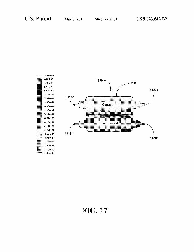
U.S. Patent May 5, 2015 Sheet 24 of 31 US 9,023,642 B2
1.01 e+p00
9.59e-01
9.09e-01
0.58e-01
9.09e°01
7.57e-01
7.07e-01
S.65e-01
5.06e-01
5.55e-01
5.04e-01
4.54e-01
4.03 a=01
3,53e-01
3.02e-01
2.52e-01
2.00 a-01
1.51 a-01
1.00e-01
4.95e-02
-1.00e-03
U.S. Patent May 5, 2015 Sheet 25 of 31 US 9,023,642 B2
24 hours
FIG-.'18A 48 lamurs
. .
72 lim-urs
_ ..
FIG. 19A
FIG. 19B
U.S. Patent May 5, 2015 Sheet 26 of 31 US 9,023,642 B2
FIG. 20A
FIG. 20B
U.S. Patent May 5, 2015 Sheet 27 of 31 US 9,023,642 B2
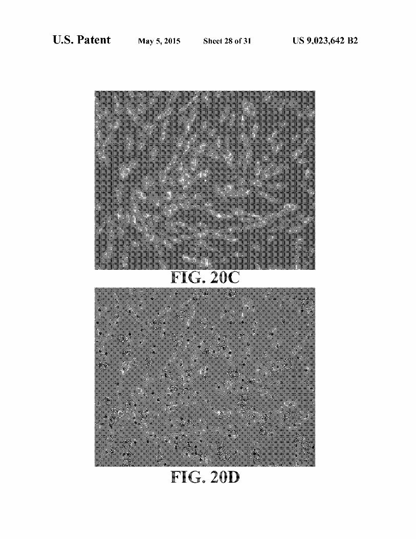
FIG. 20D
U.S. Patent May 5, 2015 Sheet 28 of 31 US 9,023,642 B2
U.S. Patent May 5, 2015 Sheet 29 of 31 US 9,023,642 B2
100
s0
60
40
20
100
80
60
40
20
0
-
100
SO
4€1
20
R 10-N
U G
100
80
60
411
20
U.S. Patent May 5, 2015 Sheet 30 of 31 US 9,023,642 B2
141 6
10
10 4
0 20 40 60 € o IN
U.S. Patent May 5, 2015 Sheet 31 of 31 US 9,023,642 B2
Hour
U.
US 9,023,642 B2 2
METHOD AND APPARATUS FOR A MINIATURE BIOREACTOR SYSTEM FOR
LONG-TERM CELL CULTURE
RELATED APPLICATIONS
This application claims priority to U.S. Provisional Patent Application Ser. No. 60/819,325, filed 7 Jul. 2006 (Jul. 7, 2006), incorporated herein by reference.
GOVERNMENT INTEREST
Some of the subject matter disclosed in this application was funded to some degree by funds supplied by the United States Government under NASA contract no. 9930-288-01 NCC 9-142.
BACKGROUND OF THE INVENTION
1. Field of the Invention The present invention relates to a bioreactor apparatus for
producing cells, selectively harvesting cells and/or tissues, and/or studying cells and/or tissues in vitro under different conditions over short or long time periods, and methods for making and using same.
More specifically, the invention relates to a bioreactor apparatus for producing cells, selectively harvesting cells and/or tissues, and/or studying cells and/or tissues in vitro under different conditions over short or long time periods, where the apparatus includes a laminar flow chamber having a plurality of cell proliferation zones, each zone having an associated inlet and outlet. The apparatus also includes a fluid handling system and a gas handling system, where the two systems are adapted to seed or inoculate, feed, gasify, harvest, stress, and/or study cells over short or long time periods. The apparatus can also include a housing containing the chamber and systems, where the housing includes pressure, tempera-ture, humidity, etc., control systems. The apparatus can include components for automated and unmanned cell seed-ing, cell proliferating, cell stressing, cell harvesting and cell monitoring operations under antiseptic conditions and for post harvesting analysis, the apparatus can be associated with a cell fluid dynamic/analysis system, especially a micro-flu-idic cell handling and analyzing system. The invention also relates to methods for making and using same.
2. Description of the Related Art Reliable and efficient cell production is now the central
focus in the growing demand for drug development and test-ing, the creation of artificial organs, the creation of engi-neered tissue, the production of active proteins made by genetically engineered cells, the production of hormones, antibodies, or enzymes, the preparation of viral vaccines, and the advanced understanding of biological processes. Addi-tionally, efforts have been directed to the understanding of cell growth and behavior upon exposure to stressors, cell-to-cell biocompatibility, tissue healing processes, cell and tissue toxicity, cell apoptosis, cell and tissue chemotaxis, and cell and tissue mechanotaxis. Some of these studies require the simultaneous production of cell cultures within the same bioreactor and in a parallel fashion.
One of the crucial problems associated with cell produc-tion is that it is time consuming, expensive, and requires skilled operators. To overcome these barriers, some attempts have been made to manufacture bioreactors and develop methods for optimizing cell production and for studying cell chemotaxis and mechanotaxis.
U.S. Pat. No. 5,153,131 (Wolf et al.) discloses a suspension cell culture system where a culture chamber is rotatable about a horizontal axis and has a vertical large area oxygen trans-missible membrane spaced a distance about 0.25 inches less
5 than 1.0 inches from a facing vertical wall surface for effec-tive transmission of oxygen to cells in suspension in the culture chamber. The facing vertical wall surface can be a dialysis membrane for exchange of fresh nutrient from a dialysis chamber with cell waste product in the culture cham-
10 ber. U.S. Pat. No. 5,496,722 (Goodwin et al.) disclosed a nor-
mal mammalian tissue and the culturing process has been developed for the three groups of organ, structural and blood tissue. The cells are grown in vitro under microgravity culture
15 conditions and form three dimensional cells aggregates with normal cell function. The microgravity culture conditions may be microgravity or simulated microgravity created in a horizontal rotating wall culture vessel.
U.S. Pat. No. 5,763,279 (Schwarz et al.) disclosed an appa- 20 ratus and method of use for a new simply constructed biore-
actor made at least partially of gas permeable materials. The bioreactor is useful for culturing cells and tissues in suspen-sion in a liquid nutrient medium with minimum turbulence. The bioreactormay include ports for easy access to the vessel
25 culture, allowing the growth substrate to be varied for opti-mum performance. A method for culturing cells using the disclosed bioreactor is also described.
U.S. Pat. No. 6,867,040 B2 (Helmstetter et al.) disclosed an apparatus and methods directed to a perfusion culture system
30 in which a rotating bioreactor is used to grow cells in a liquid culture medium, while these cells are attached to an adhesive-treated porous surface. As a result of this arrangement and its rotation, the attached cells divide, with one cell remaining attached to the substrate, while the other cell, a newborn cell
35 is released. These newborn cells are of approximately the same age, that are collected upon leaving the bioreactor. The populations of newborn cells collected are of synchronous and are minimally, if at all, disturbed metabolically.
Thus, there is a need in the art for an improved bioreactor 40 apparatus for perfusing cells with a medium; controlling an
amount of fresh and/or recirculated medium through inlet valves supplying medium to each laminar zone in the biore-actor apparatus; controlling waste collection through an out-let valve; controlling temperature, gas transport, gas
45 exchange, and humidity; inoculating cells through an inocu-lation port; sampling/assaying cells, supernatant, and cell products; selectively harvesting cells; and selectively harvest-ing cell products.
50 SUMMARY OF THE INVENTION
Apparatuses The apparatus of the present invention provides a laminar
flow bioreactor apparatus including a laminar flow cell cul- 55 ture assembly including a laminar flow chamber having a
plurality of cell proliferation zones. Each zone is adapted to support cell proliferation. In embodiments involving the use of anchorage cells, each zone includes at least one surface comprising a substrate conducive to cell growth and where
60 each zone includes an inlet and an outlet. However, the sub-strate can also be a test substrate to determine anchorage propensity, anchorage antagonism, or other substrate effects on cell inoculation, proliferation, harvesting, etc. Each inlet includes a fluid diffuser and each outlet includes a fluid col-
65 lector. The apparatus also includes a fluid handling system, where
the system supplies medium and/or gas to the zones at a
US 9,023,642 B2 3
medium flow rate and at a gas concentration sufficient to maintain laminar flow throughout the zones and sufficient to support cell proliferation throughout the zones. In certain embodiments, the chamber has a volume of about 1 mL. In other embodiments, the chamber has a volume less than 1 mL. However, the volume of the chamber can be adjusted to any desired volume, provided that laminar flow is maintained in each of the zones and sufficient gas transport and exchange can occur throughout the zones to maintain all the cells in each zone under substantially the same conditions. It should be recognized that each zone can be supplied with different media and different gases. The zones are adapted to support single cell layers growing on the conducive substrate or to support multiple cells layer, where a first layer is seeded and proliferated onto the conducive substrate and each additional layer deposited onto the previously proliferated layer or to support the preparation of a layer made of a plurality of different cell types, where a first cell type is seeded and proliferated on the conducive substrate and one or more addi-tional cell types are deposited so that the layer comprises a mixture of the cell types. Single cell layers having multiple cell types are ideally suited for studying the effects of stem cells on different cell lines or the effects of cancer cells on different cell lines.
The apparatus can also include a plurality of laminar flow cell chambers and a more sophisticated fluid and gas handling system so that the medium flowing into each zone of each chamber can be the same or different and the cells from each zone of each chamber can be independently or collectively harvested and/or cell products from each zone of each cham-ber can be independently or collectively collected. The appa-ratus can also include a sealed and antiseptic housing with the bio-reactor apparatus disposed therein, where the housing includes temperature, pressure, gas, humidify, etc. controller.
The fluid/gas handling system includes inlet valves, outlet valves, an inoculation port, and a cell sampling/assaying port, where the fluid handling system is adapted to perfuse cells in the each zone of each chamber with a medium, control an amount of the medium entering the each zone of each cham-ber via the inlet valves, and control waste collection via the outlet valves. The fluid/gas handling system and the housing are adapted to control a temperature of the bioreactor appa-ratus, a pressure in the housing, a humidity in the housing, a gas transport rate into each zone of each chamber, and a gas exchange rate in each zone of each chamber. The fluid/gas handling system is also adapted to inoculate the chamber with cells through the inoculation port, and to sample and assay cells, supernatants, and cell products through the sampling/ assaying port, to selectively harvest cells, and to selectively collect cell products. Each chamber is adapted to support a plurality of cell growth regions, where the regions separated one from the other without the need of a physical barrier such as a filters or wall. Bio-Sensors or Bio-Sentinels
The present invention also provides a monitoring system including a bioreactor apparatus of this invention, where cells in the apparatus are used as bio-sensor or bio-sentinels to evidence hazardous conditions and to alter personnel in potentially hazardous environments of a hazardous condition such as a chemical, biological, physical, radiation, or other hazardous condition. Systems
The present invention also provides a monitoring system including a bioreactor apparatus ofthis invention, where cells in the apparatus are exposed to oxygen deprivation, nutrient deprivation, toxins, pathogens and/or mutagenes while moni-
4 toring the response of the cells, such as mutations, death, retarded growth, uncontrolled growth, etc. Methods
The present invention also provides a method including the 5 steps of seeding, producing, and harvesting cells from a biore-
actor apparatus of this invention. The method can also include the step of studying cells in the bioreactor apparatus during seeding, producing or proliferating, harvesting and/or study-ing cell seeding, producing or proliferating, and harvesting.
10 The method can also include the step of monitoring cell seeding, producing or proliferating and harvesting, when exposing cells in the bioreactor apparatus to experimental conditions, where the experimental conditions can include changes in temperature, changes in pressure, changes in
15 humidity, changes in buffers, changes in nutrients, changes in gases and gas mixtures, exposure to pharmaceuticals, expo-sure to toxins, exposures to mutagenes, exposure to patho-gens, or exposure to other harmful or stimulating conditions or additives.
20 The present invention also provides a method including the steps of seeding, producing, studying and/or harvesting cells using a bioreactor apparatus of this invention. The bioreactor apparatus of this invention is ideally suited for studying: (1) cell chemotaxis, mechanotaxis, apoptosis, artificial organ,
25 skin and other tissue growth, (2) cell production of active proteins, hormones, antibodies, or enzymes, (3) preparing viral vaccines, and (4) drug testing. The method can also include analyzing harvested or collected cells from the appa-ratus using advanced analytical techniques, tools and equip-
30 ments.
BRIEF DESCRIPTION OF THE DRAWINGS
The invention can be better understood with reference to 35 the following detailed description together with the appended
illustrative drawings in which like elements are numbered the same.
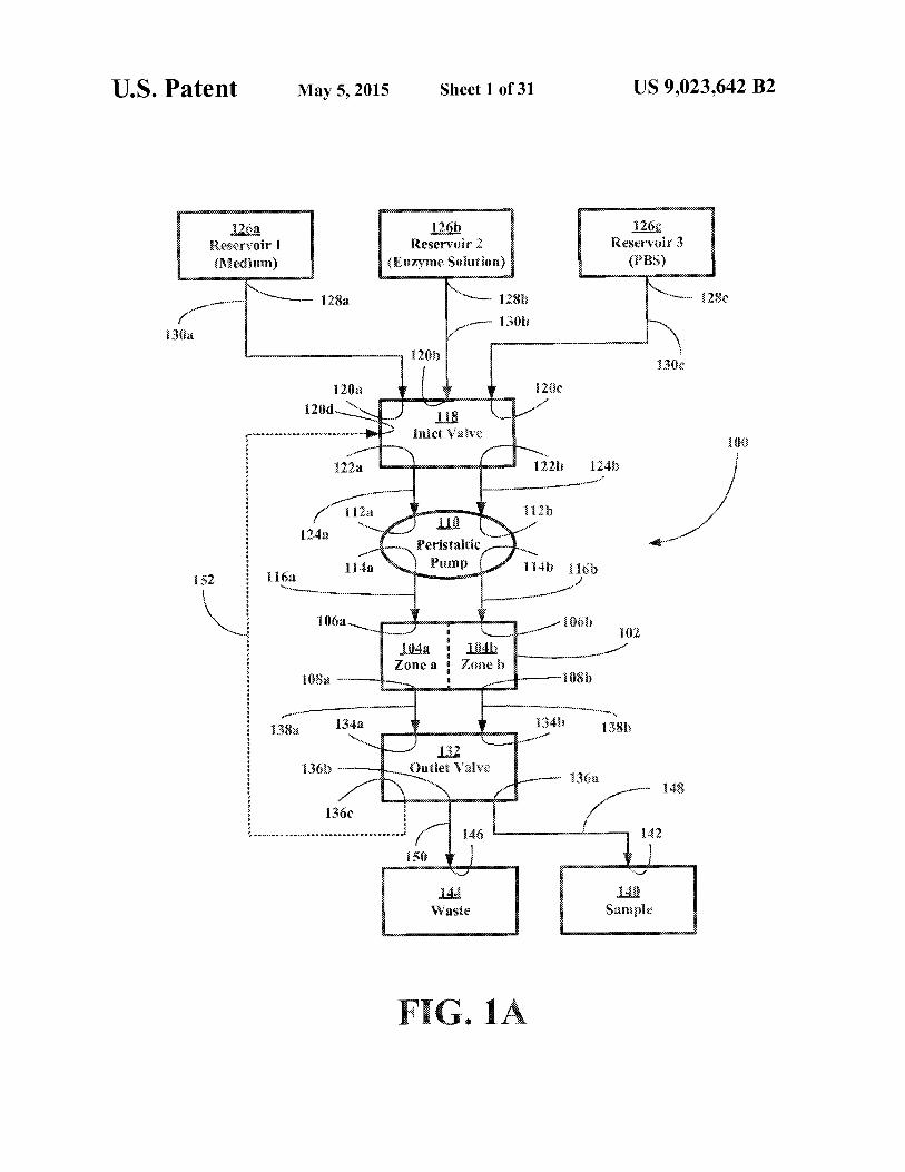
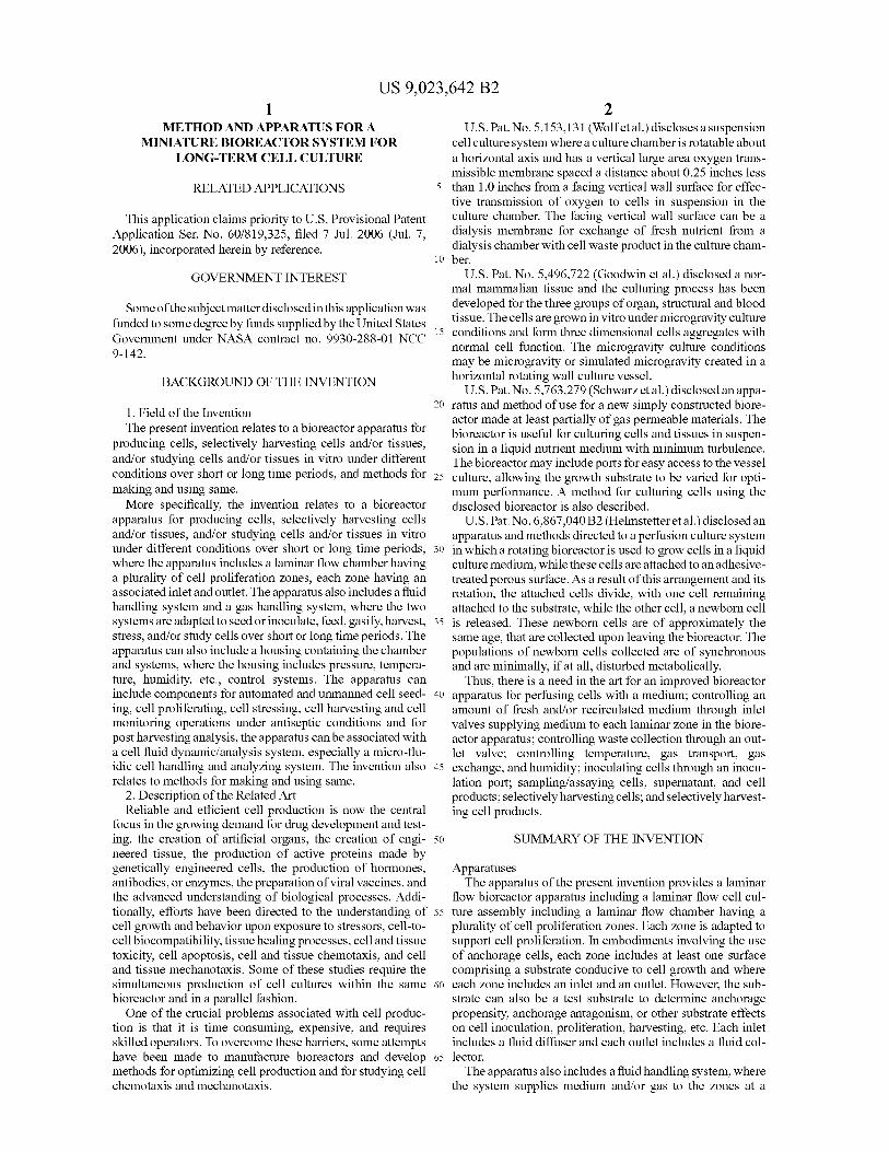
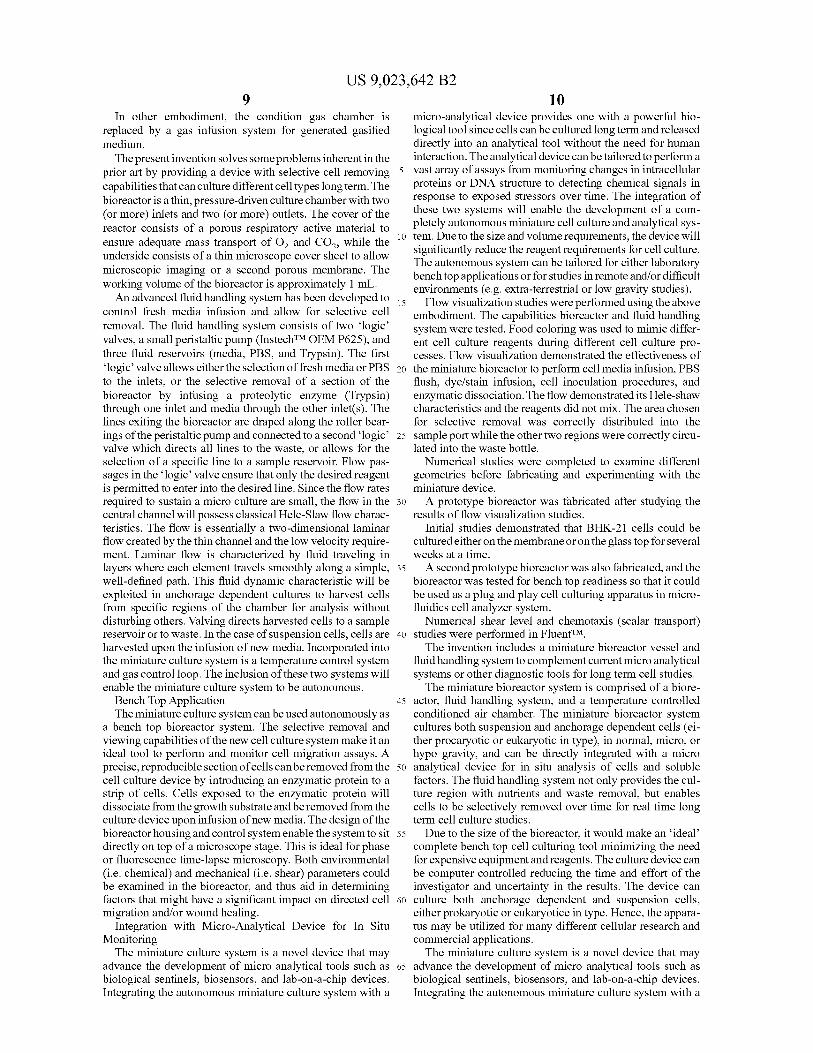
FIG. 1A depicts a block and flow diagram of an embodi-ment of a bioreactor apparatus of the invention.
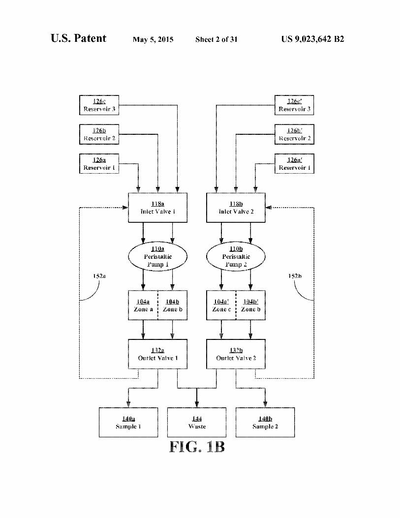
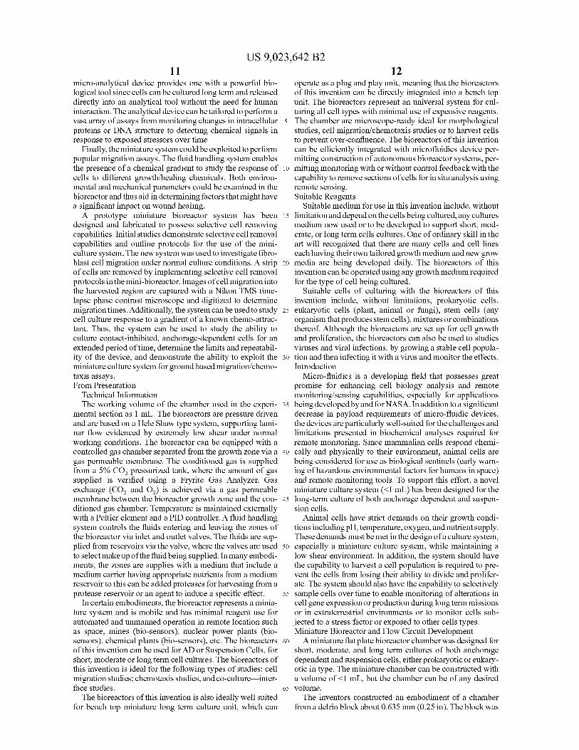
40 FIG. 1B depicts a block and flow diagram of another embodiment of a bioreactor apparatus of the invention.
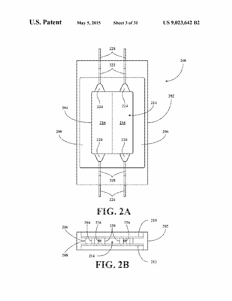
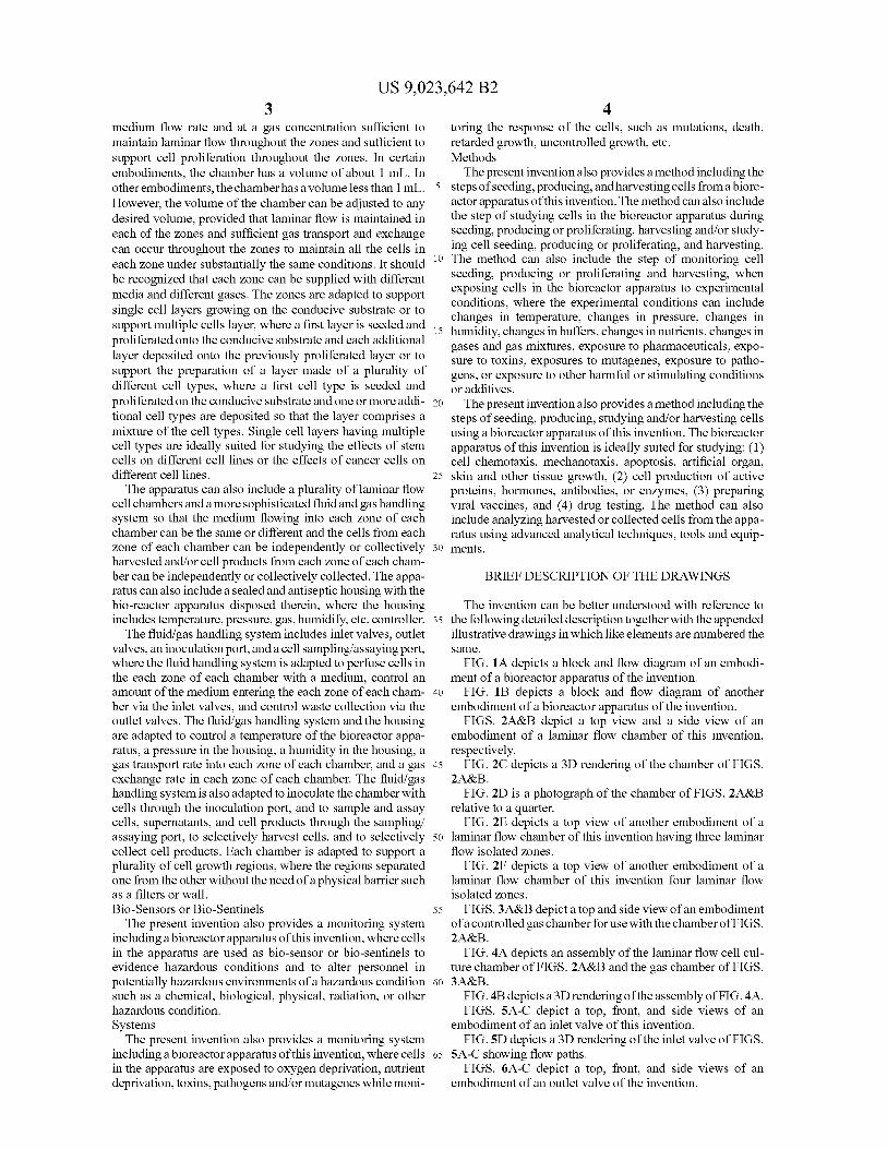
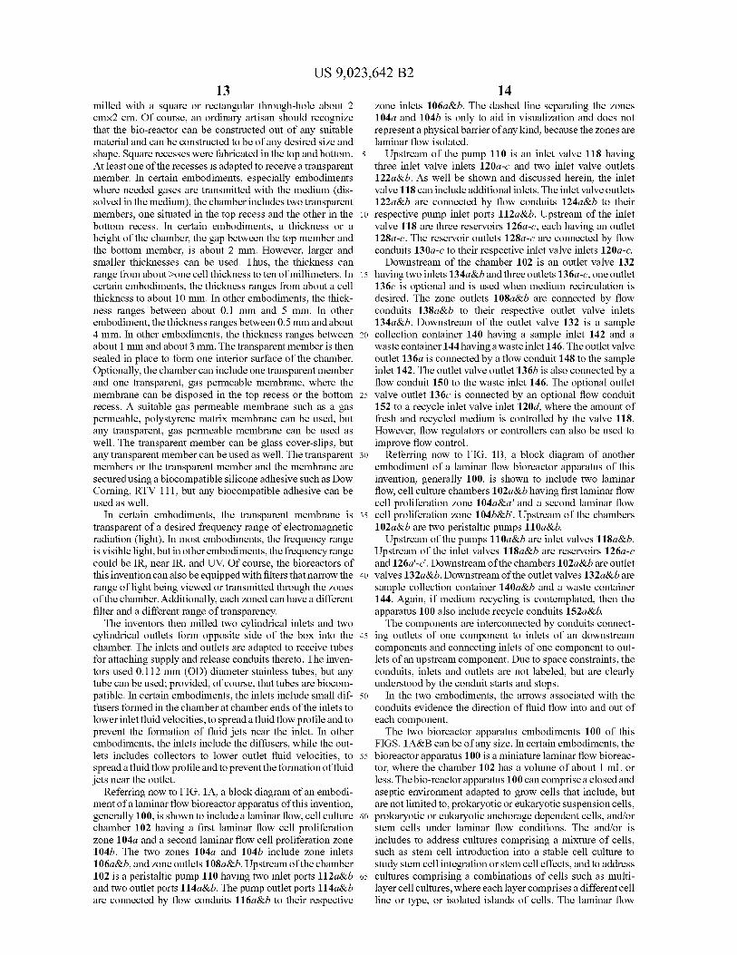
FIGS. 2A&B depict a top view and a side view of an embodiment of a laminar flow chamber of this invention, respectively.
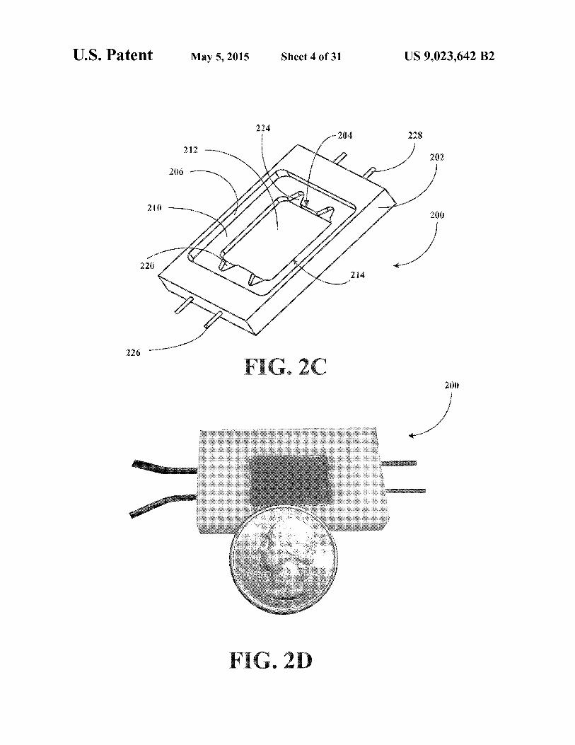
45 FIG. 2C depicts a 3D rendering of the chamber of FIGS. 2A&B.
FIG. 2D is a photograph of the chamber of FIGS. 2A&B relative to a quarter.
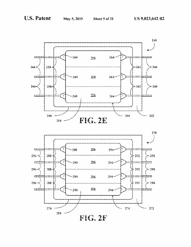
FIG. 2E depicts a top view of another embodiment of a 50 laminar flow chamber of this invention having three laminar
flow isolated zones. FIG. 2F depicts a top view of another embodiment of a
laminar flow chamber of this invention four laminar flow isolated zones.
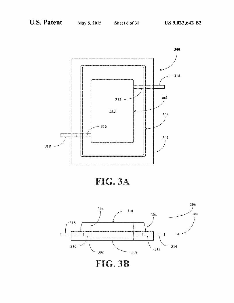
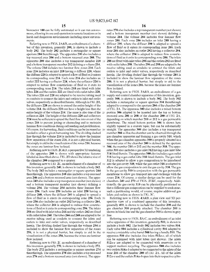
55 FIGS. 3A&B depict a top and side view of an embodiment of a controlled gas chamber for use with the chamber of FIGS. 2A&B.
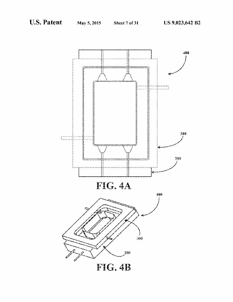
FIG. 4A depicts an assembly of the laminar flow cell cul-ture chamber of FIGS. 2A&B and the gas chamber of FIGS.
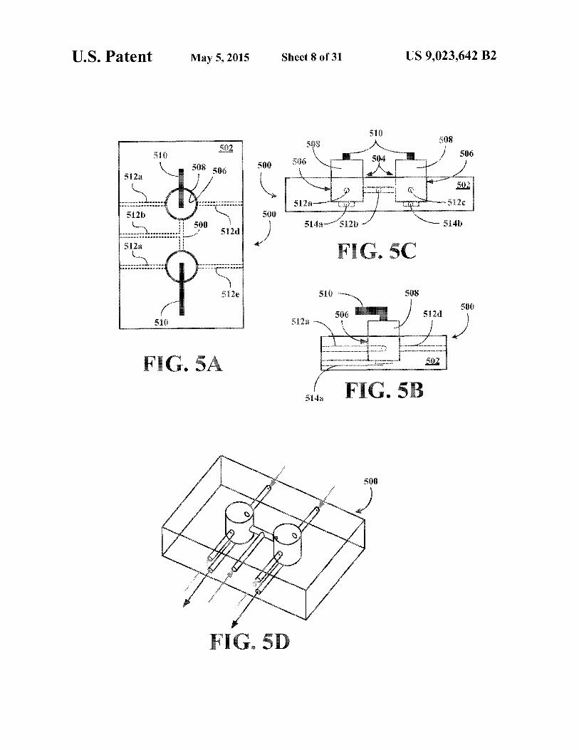
60 3A&B. FIG. 4B depicts a 3D rendering of the assembly of FIG. 4A. FIGS. 5A-C depict a top, front, and side views of an
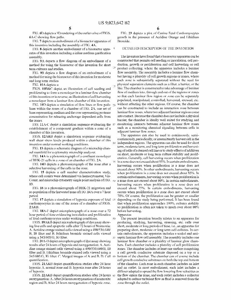
embodiment of an inlet valve of this invention. FIG. 5D depicts a 3D rendering of the inlet valve of FIGS.
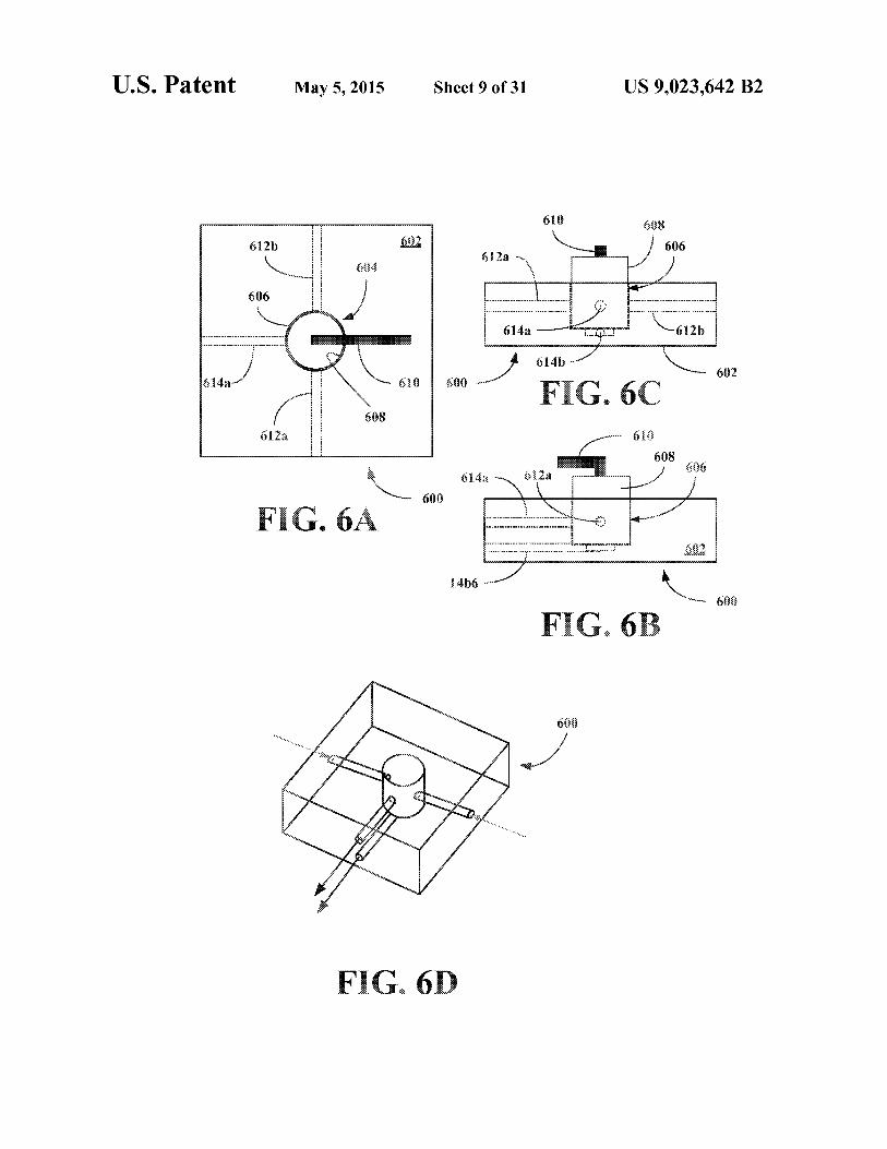
65 5A-C showing flow paths. FIGS. 6A-C depict a top, front, and side views of an
embodiment of an outlet valve of the invention.
US 9,023,642 B2 5
FIG. 6D depicts a 3D rendering of the outlet valve of FIGS. 6A-C showing flow paths.
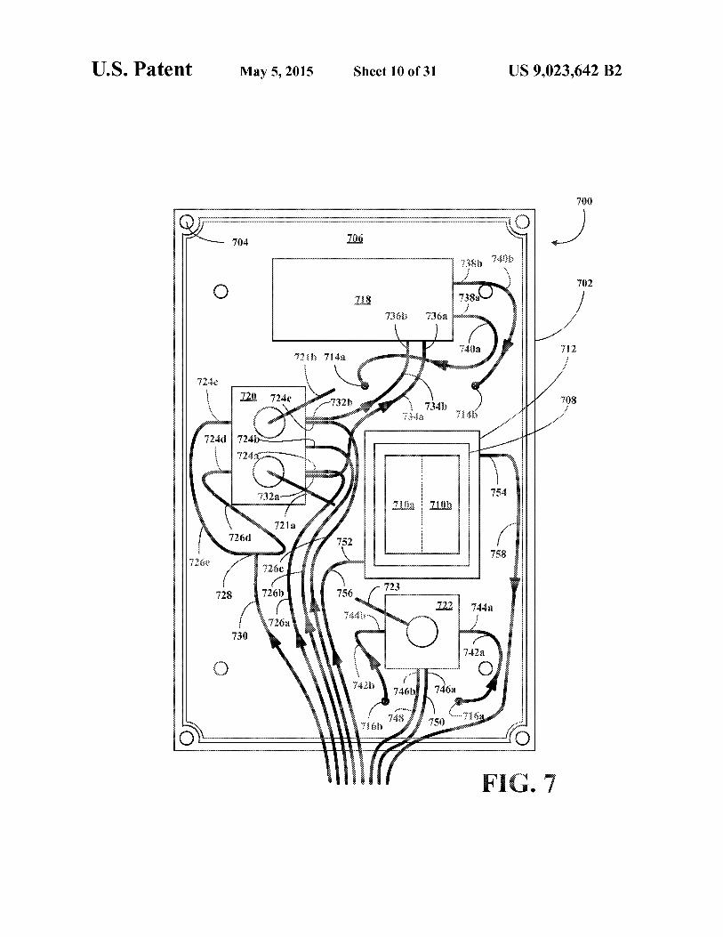
FIG. 7 depicts an embodiment of a bioreactor apparatus of this invention including the assembly of FIG. 4A.
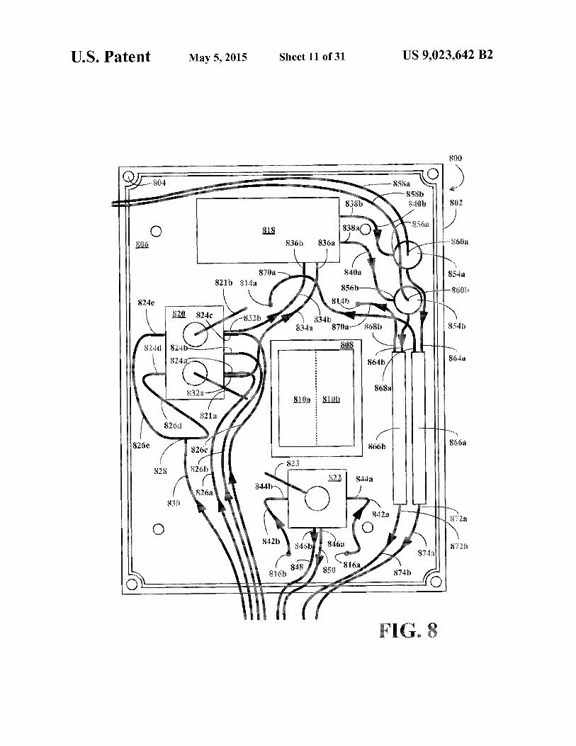
FIG. 8 depicts another embodiment of a bioreactor appa-ratus of this invention including a inline medium gasification assembly.
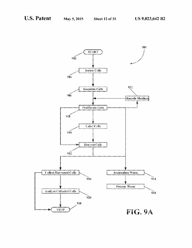
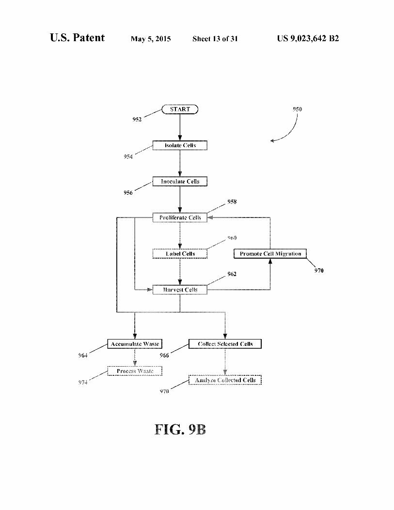
FIG. 9A depicts a flow diagram of an embodiment of a method for using the bioreactor of this invention for short term cultures and studies.
FIG. 9B depicts a flow diagram of an embodiment of a method for using the bioreactor of this invention for moderate and long term studies.
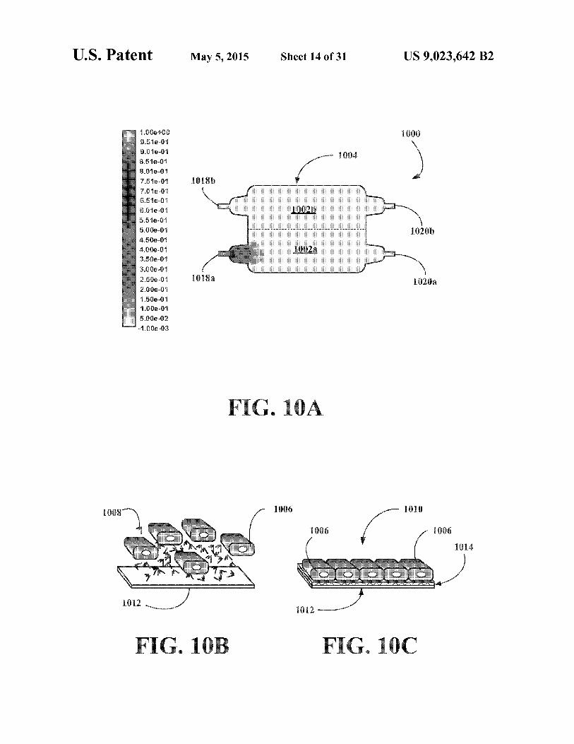
FIG. 10A depicts a FIGS. 1OB&C depict an illustration of cell seeding and
proliferating to form a monolayer in a laminar flow chamber of thi s invention or in reverse, an illustration of cell harvesting a monolayer from a laminar flow chamber of this invention.
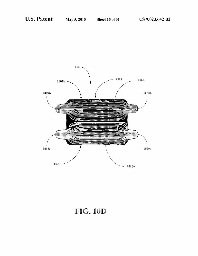
FIG. 10D depicts a simulation of flow lines or flow path-lines within the zones of a chamber of FIG. 2A, one set of lines representing medium and the over representing protease concentration for releasing anchorage dependent cells from the zones.
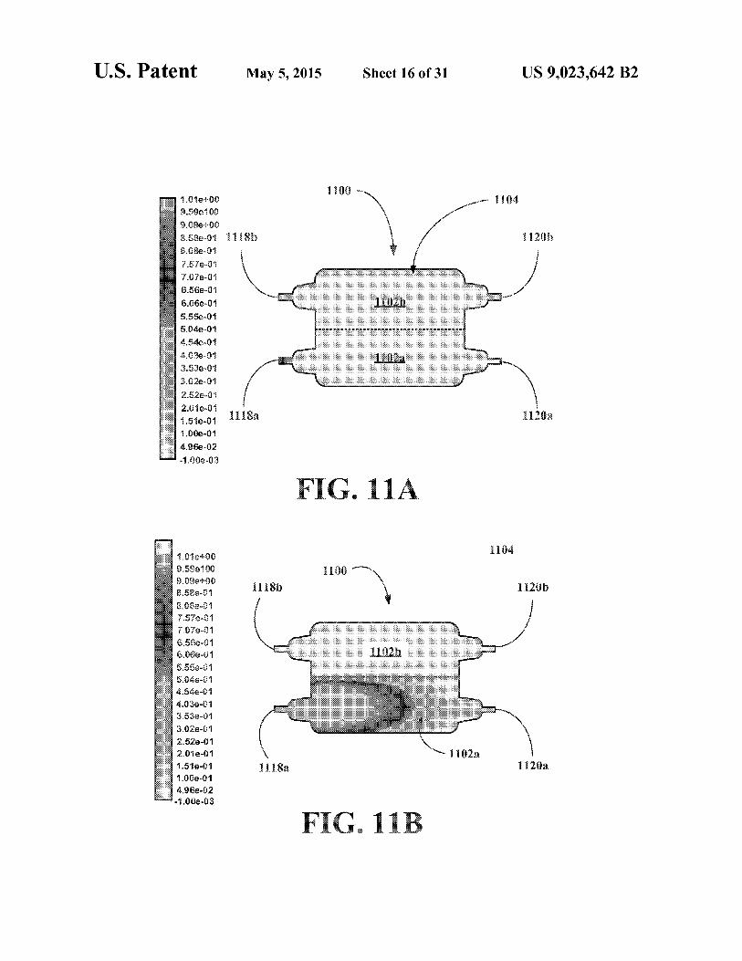
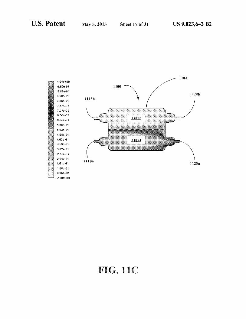
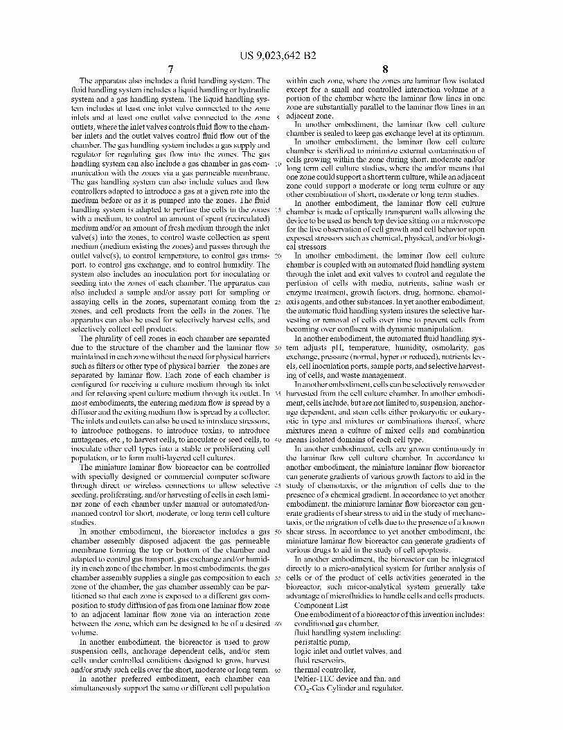
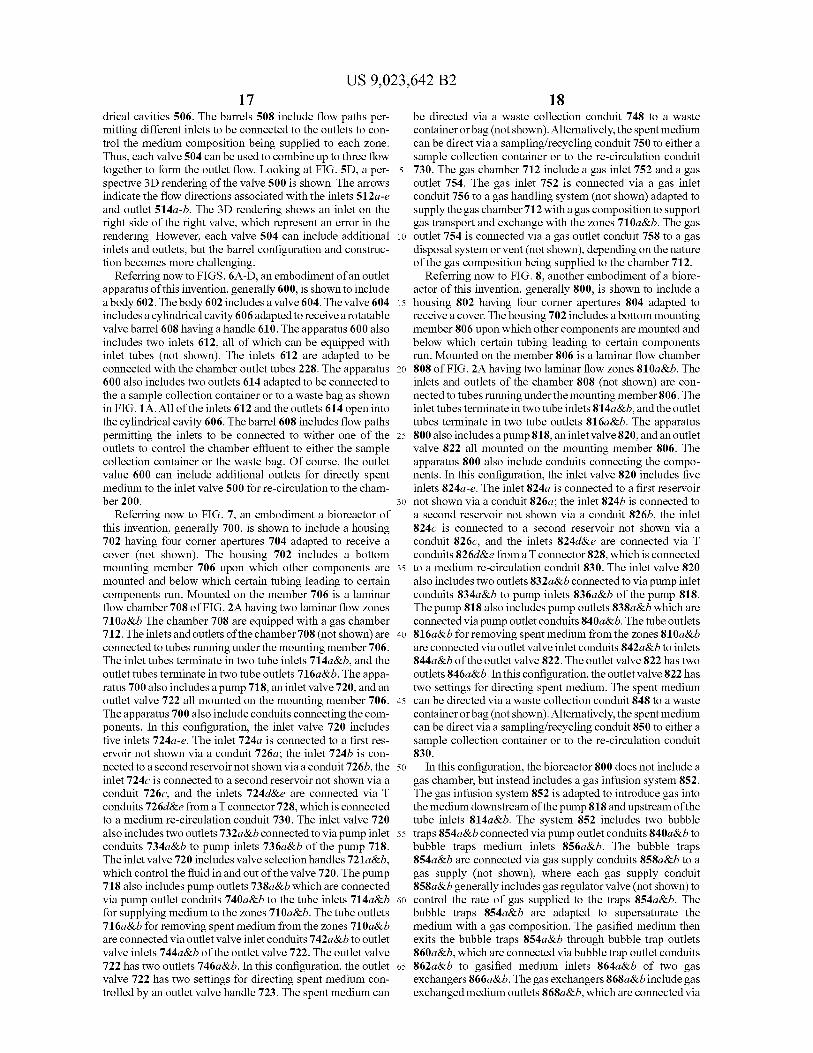
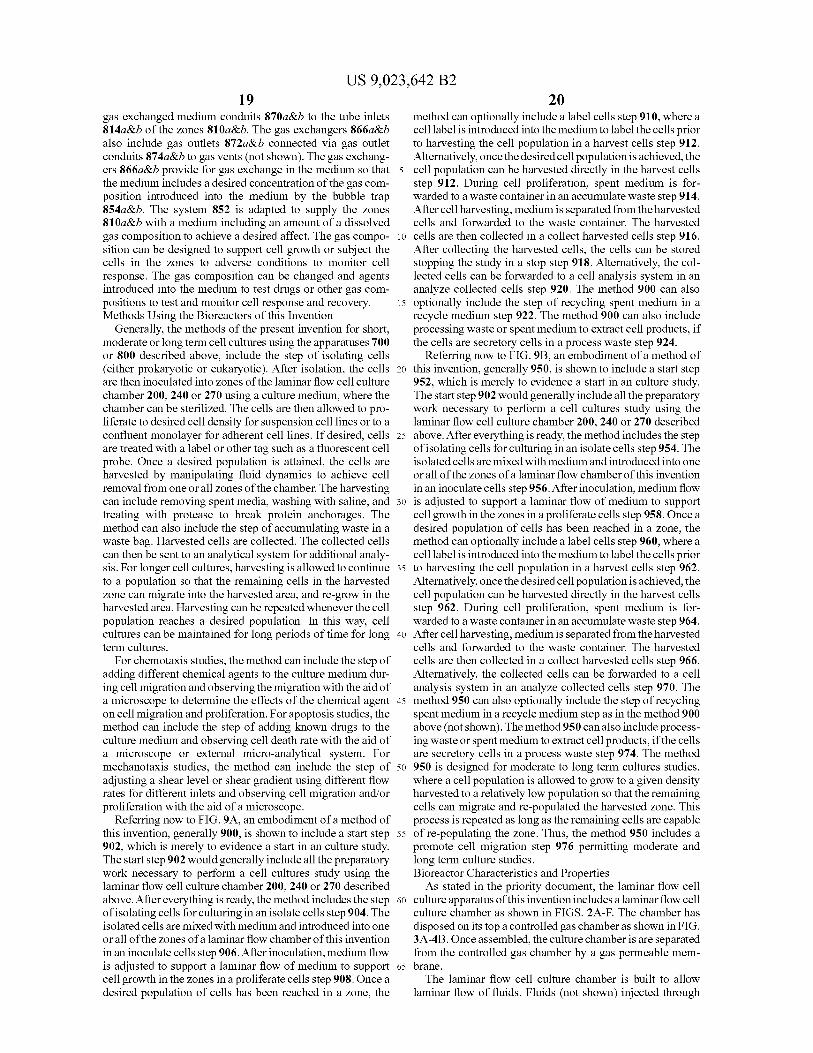
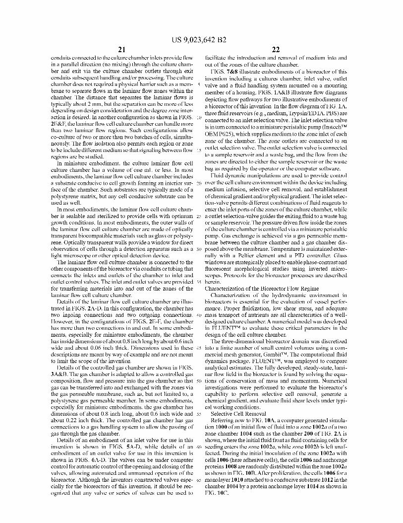
FIG. 11A-C depict a simulation sequence evidencing the establishment of a component gradient within a zone of a chamber of this invention.
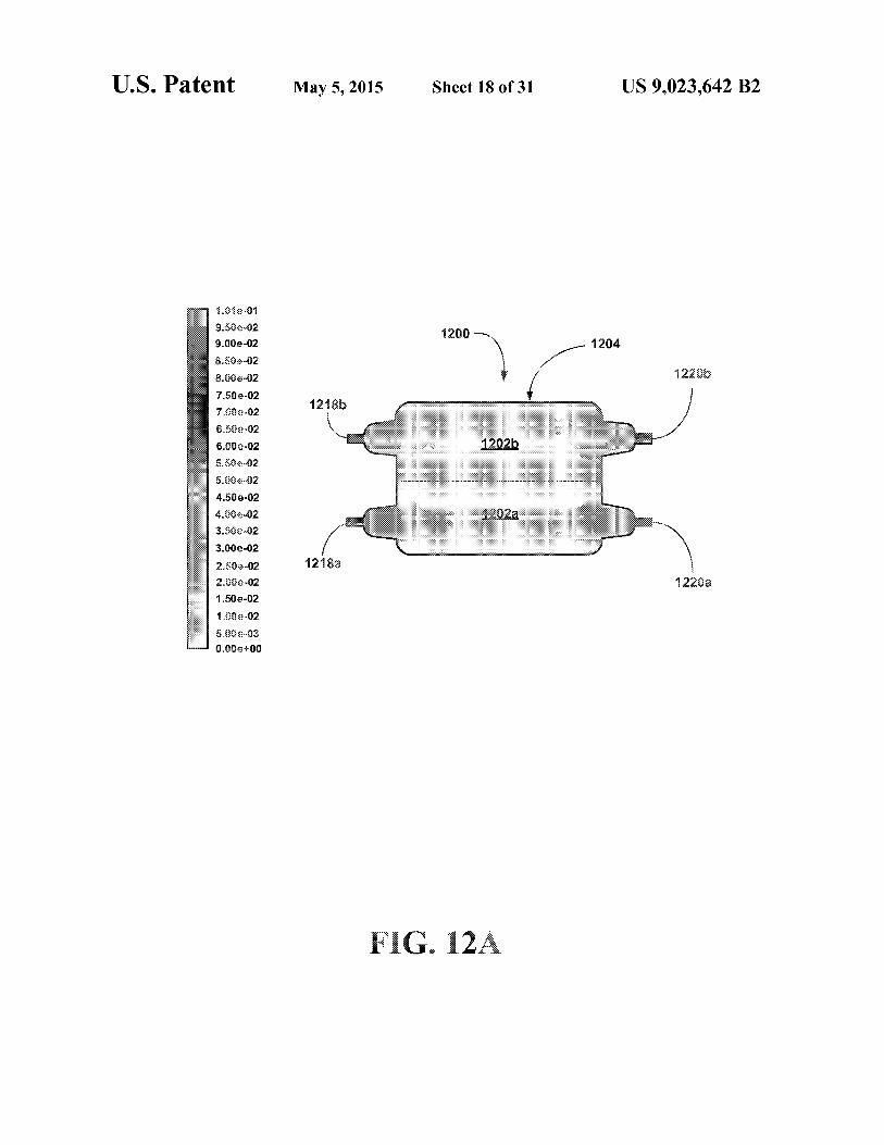
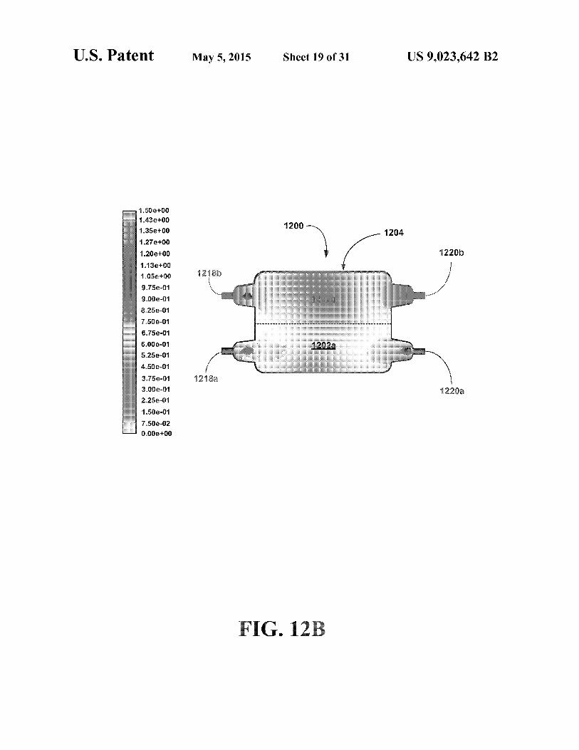
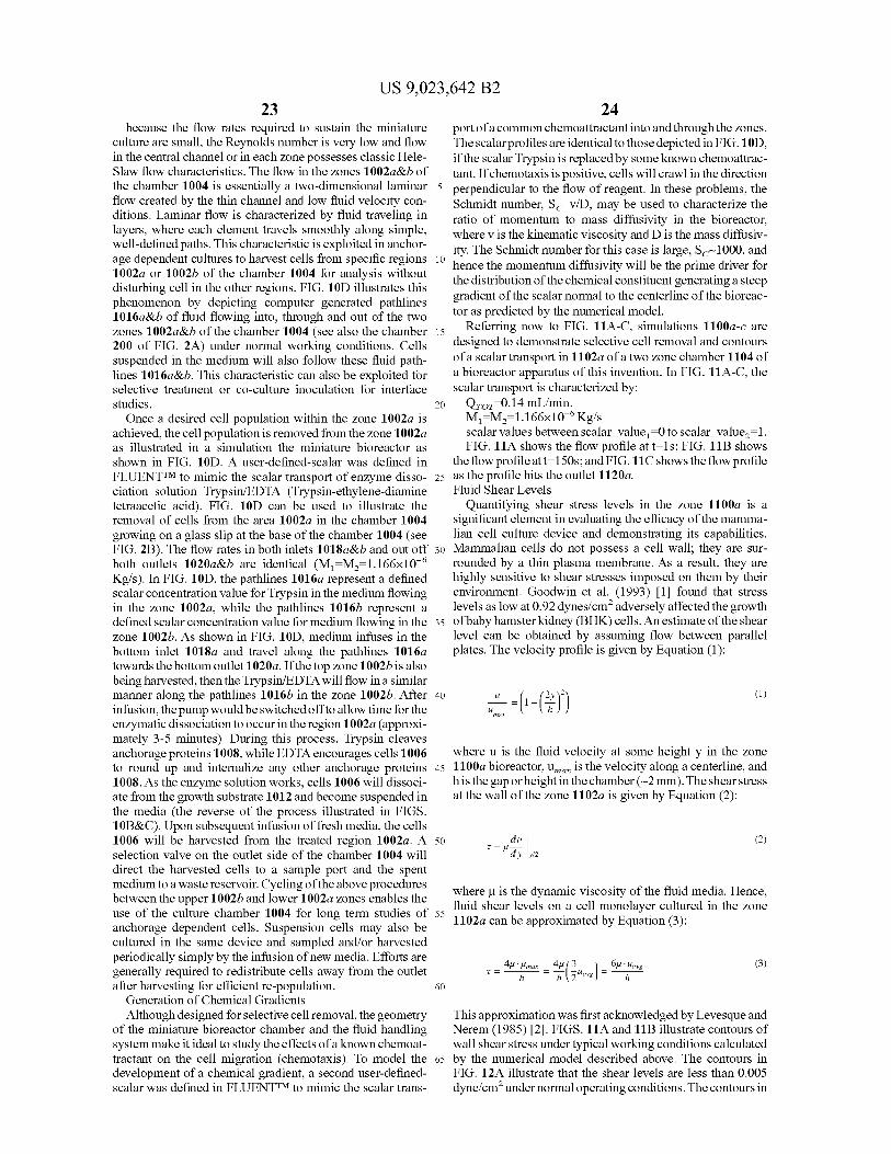
FIGS. 12A&B depict a simulation sequence evidencing wall shear stress levels produced within a chamber of this invention under normal working conditions.
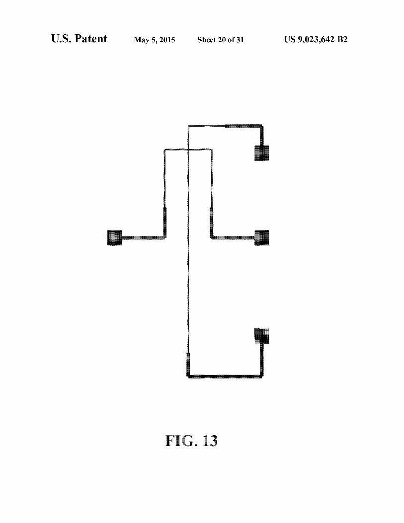
FIG. 13 depicts a schematic diagram of a microchip chan-nel manifold for a cytometry microchip analyzer.
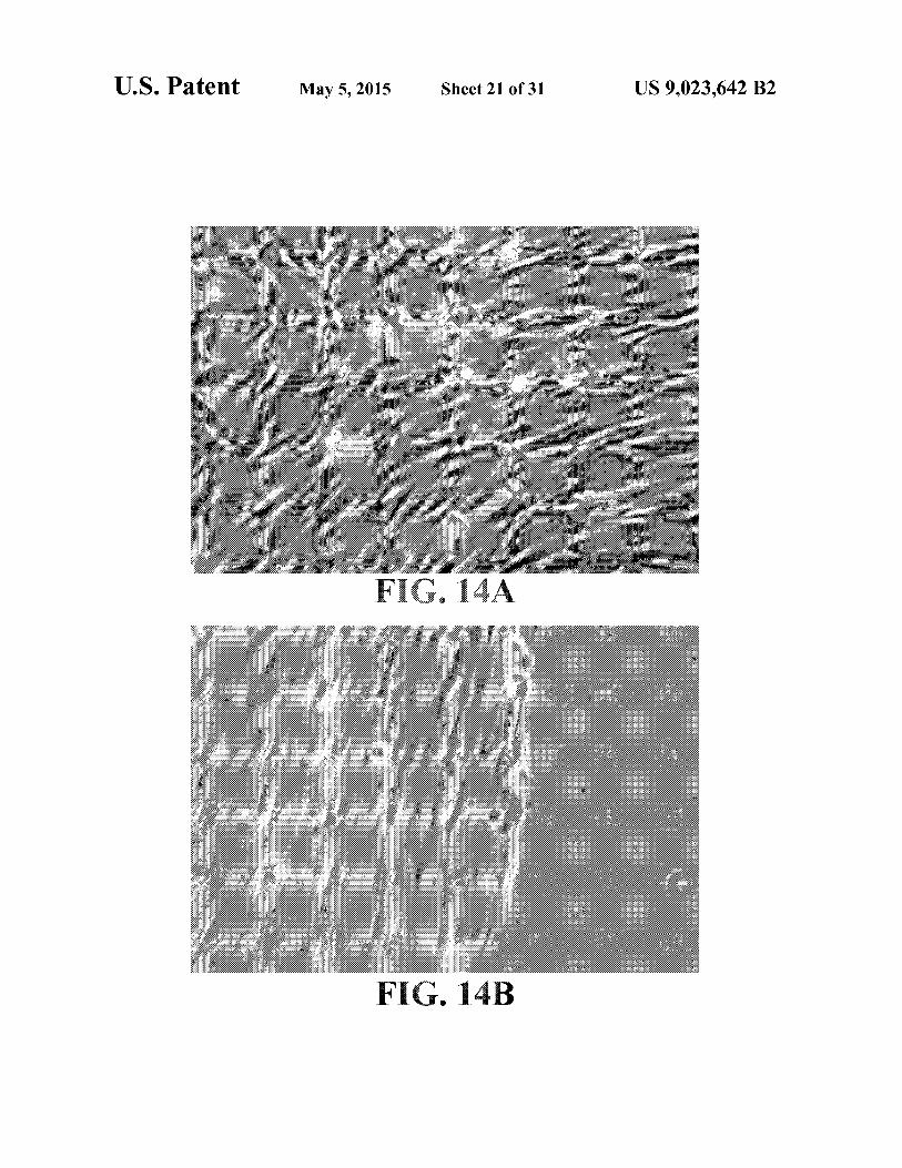
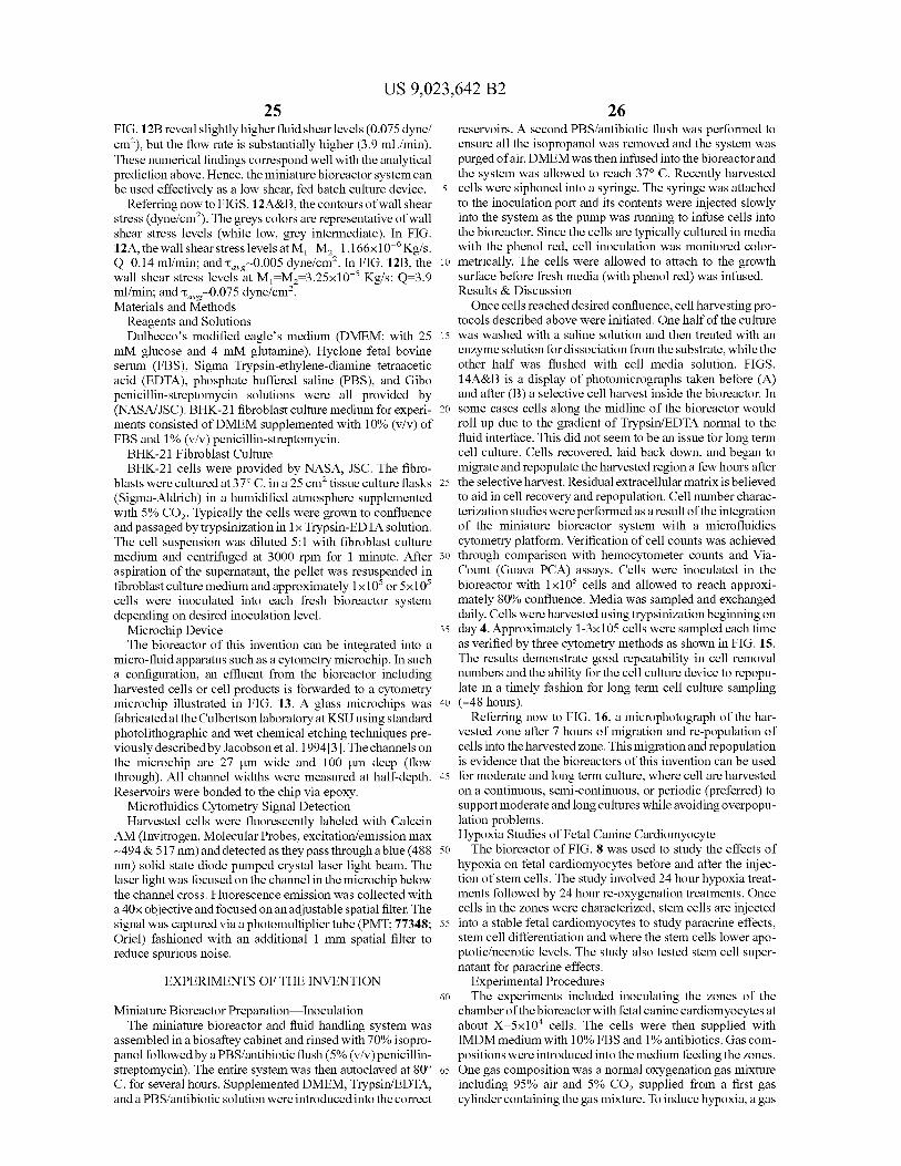
FIG. 14A is a photomicrograph of a confluent monolayer of BHK-21 cells in a zone of an chamber of FIG. 2A.
FIG. 14B depicts a photomicrograph of the zone after a selective harvesting of the cells in the zone.
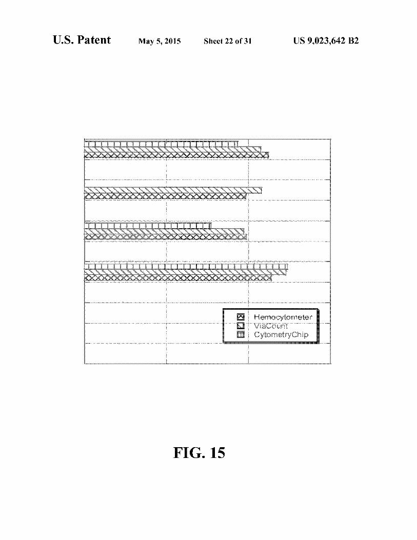
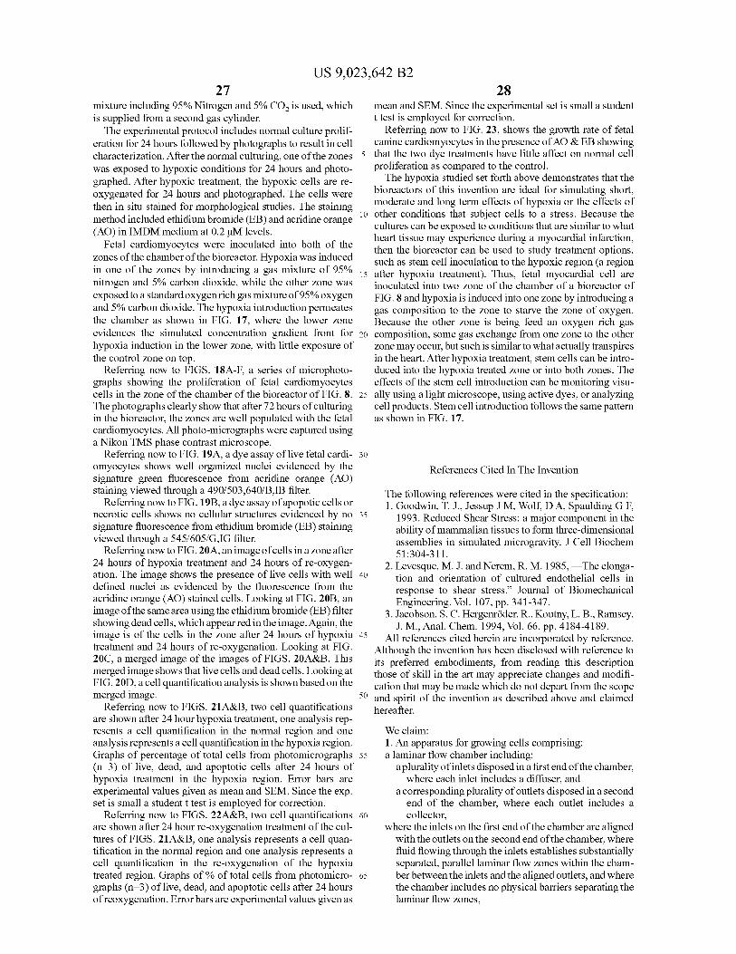
FIG. 15 depicts a cell number characterization study, where cell counts were determined via hemocytometer, Via-Count, and microchip cytometry single point analysis of FIG. 13.
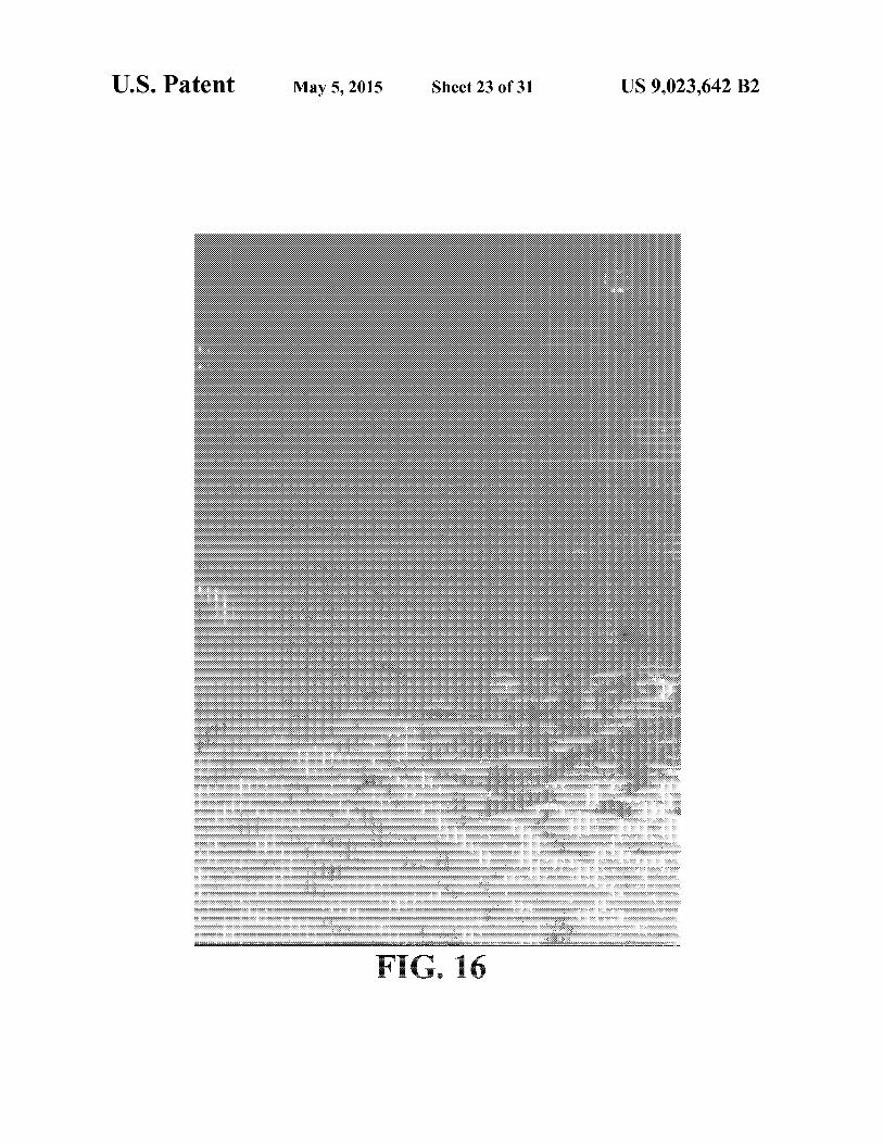
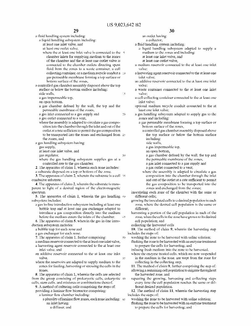
FIG. 16 is a photomicrograph of BHK-21 migration and re-population of the harvested zone of FIG. 14A over a 7 hour period
FIG. 17 depicts a simulation of hypoxia exposure of fetal cardiomyocytes in one of the zones of a chamber of FIGS. 2A&B.
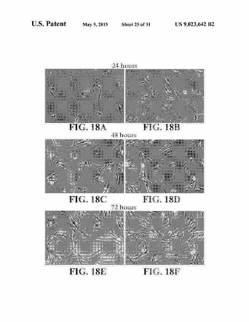
FIG. 18A-F depict microphotograph of a zone over a 72 hour period of time evidencing inoculation and proliferation of fetal cardiomyocytes under working conditions.
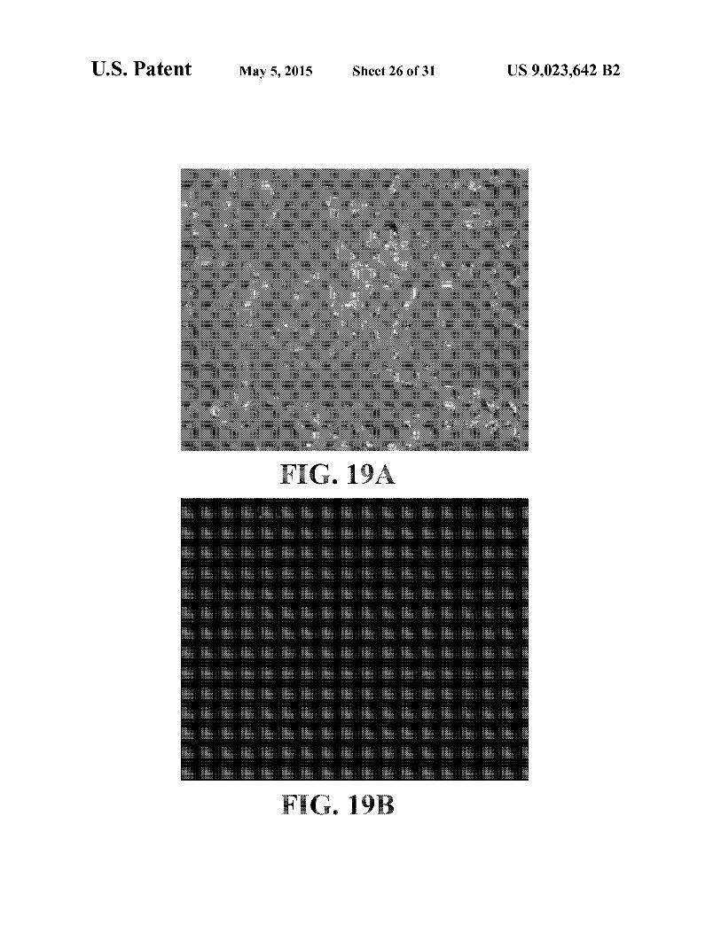
FIGS.I9A&B depict microphotograph of dye assay show-ing live cells and apoptotic cells after 72 hours of Normoxia: A. Acridine orange stained cells viewed using a 490/530,640/ B, IB filter and B. Ethidium bromide stained cells viewed using a 545/605/G, IG filter.
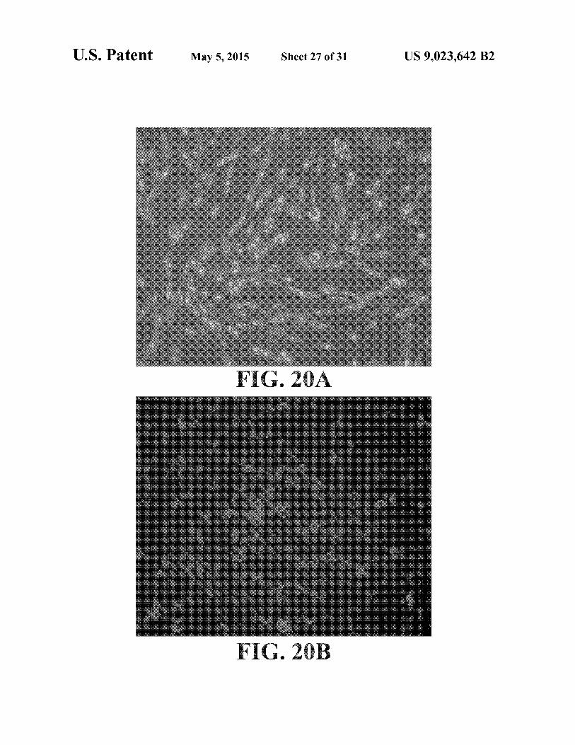
FIG. 20A-D depict microphotograph of dye assay showing results after 24 hours of hypoxia and reoxygenation: A. Acri-dine orange stained cells viewed using a 490/530,640/B, IB filter and B. Ethidium bromide stained cells viewed using a 545/605/G, IG filter. C. Merged images of A and B. D. Cell quantification.
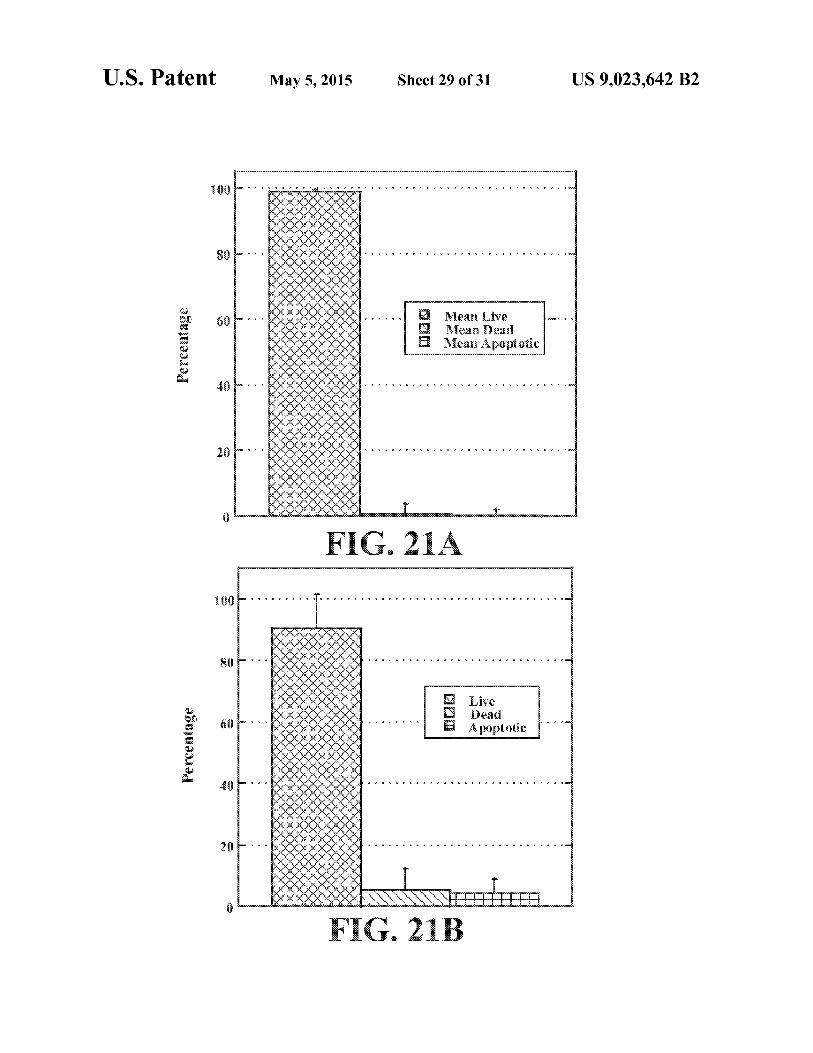
FIGS. 21A&B depict quantification studies after 24 hour hypoxia: A. normal zone and B. hypoxia zone after 24 hours of hypoxia.
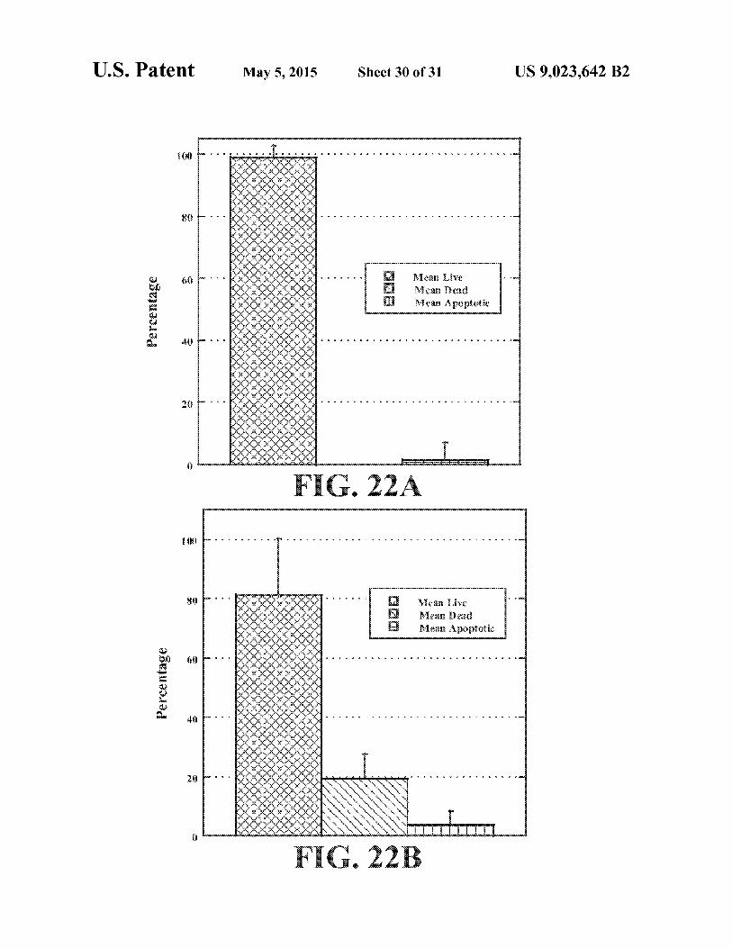
FIGS. 22A&B depict quantification studies after 24 hours reoxygenation: A. After 24 hours reoxygenation of normoxitc region and B. After 24 hours reoxygenation of hypoxic zone.
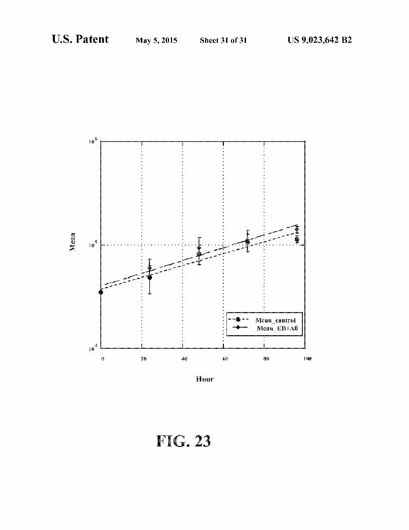
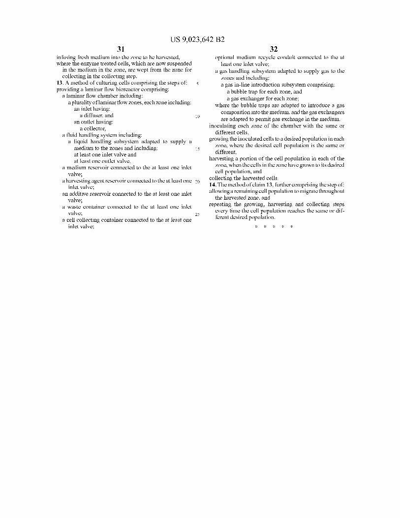
6 FIG. 23 depicts a plot of Canine Fetal Cardiomyocytes
growth in the presence of Acridine Orange and Ethidium Bromide.
5 DETAILED DESCRIPTION OF THE INVENTION
The inventors have found that a bioreactor apparatus can be constructed that permits cell seeding or inoculation, cell pro-duction, growth or proliferation and cell harvesting or cell
to product collecting, where the apparatus includes a laminar flow assembly. The assembly includes a laminar flow cham-ber having a plurality of cell growth regions or zones, where each zone is substantially separated without the need for
15 physical separation elements such as a filter, a barrier, or the like. The chamber is constructed to take advantage of laminar flow of medium into, through and out of the regions or zones so that each laminar flow region or zone can be separately populated, manipulated, controlled, harvested, stressed, etc.
20 without affecting the other regions. Of course, the chamber can be constructed to include an interaction zone between laminar flow zones, where two adjacent laminar regions come into contact. Because the chamber does not include a physical barrier, the chamber is ideally well suited for studying and
25 monitoring interacts between adjacent laminar flow zones such as a monitoring chemical signaling between cells in adjacent laminar flow zones.
The apparatus can also be used to continuously, semi-continuously, periodically, or intermittently harvest cell in the
30 independent regions. The apparatus can also be used for short term, moderate term, and long term proliferation and harvest-ing of cells of a desired cell line or to study effects of additives on short, moderate or long term culture stability and prolif-eration. Generally, cell harvesting occurs when proliferation
35 in a zone does not exceed about 95%. In certain embodiments, harvesting occurs when proliferation is a zone does not exceed about 90%. In other embodiments, harvesting occurs when proliferation is a zone does not exceed about 85%. In certain embodiments, harvesting occurs when proliferation is
4o a zone does not exceed about 80%. In certain embodiments, harvesting occurs when proliferation is a zone does not exceed about 75%. In certain embodiments, harvesting occurs when proliferation is a zone does not exceed about 70%. Of course, the proliferation can be greater or smaller
45 depending on the study being performed. It has been found that when proliferation approaches 100%, cultures stability so proliferation is often not taken to much over about 80% before harvesting. Apparatus
50 The present invention broadly relates to an apparatus for producing, studying, harvesting, stressing, etc. cells over short, moderate or long periods of time, i.e., an apparatus for preparing short, moderate or long term cell cultures. In cer-tain embodiments, the apparatus includes a sealed and anti-
55 septic laminar flow cell assembly. The assembly includes one laminar flow chamber or a plurality of laminar glow cham-bers. Each chamber includes a plurality of cell proliferation zones. The chamber includes at least one surface comprising a cell growth conducive substrate disposed on a top or a
6o bottom of the chamber. The chamber can of course include cell growth conducive substrates on both the top and bottom of the chamber. Each zone in each chamber includes an inlet and an outlet. In most embodiment, each inlet includes a diffuser adapted to spread the flow lowering flow velocities as
65 the flow enters the zone, and each outlet includes a collector adapted to reduce turbulent flow as fluid is removed from the zone through the outlet.
US 9,023,642 B2 7
The apparatus also includes a fluid handling system. The fluid handling system includes a liquid handling or hydraulic system and a gas handling system. The liquid handling sys-tem includes at least one inlet valve connected to the zone inlets and at least one outlet valve connected to the zone outlets, where the inlet valves controls fluid flow to the cham-ber inlets and the outlet valves control fluid flow out of the chamber. The gas handling system includes a gas supply and regulator for regulating gas flow into the zones. The gas handling system can also include a gas chamber in gas com-munication with the zones via a gas permeable membrane. The gas handling system can also include values and flow controllers adapted to introduce a gas at a given rate into the medium before or as it is pumped into the zones. The fluid handling system is adapted to perfuse the cells in the zones with a medium, to control an amount of spent (recirculated) medium and/or an amount of fresh medium through the inlet valve(s) into the zones, to control waste collection as spent medium (medium existing the zones) and passes through the outlet valve(s), to control temperature, to control gas trans-port, to control gas exchange, and to control humidity. The system also includes an inoculation port for inoculating or seeding into the zones of each chamber. The apparatus can also included a sample and/or assay port for sampling or assaying cells in the zones, supernatant coming from the zones, and cell products from the cells in the zones. The apparatus can also be used for selectively harvest cells, and selectively collect cell products.
The plurality of cell zones in each chamber are separated due to the structure of the chamber and the laminar flow maintained in each zone without the need for physical barriers such as filters or other type of physical barrier the zones are separated by laminar flow. Each zone of each chamber is configured for receiving a culture medium through its inlet and for releasing spent culture medium through its outlet. In most embodiments, the entering medium flow is spread by a diffuser and the exiting medium flow is spread by a collector. The inlets and outlets can also be used to introduce stressors, to introduce pathogens, to introduce toxins, to introduce mutagenes, etc., to harvest cells, to inoculate or seed cells, to inoculate other cell types into a stable or proliferating cell population, or to form multi-layered cell cultures.
The miniature laminar flow bioreactor can be controlled with specially designed or commercial computer software through direct or wireless connections to allow selective seeding, proliferating, and/or harvesting of cells in each lami-nar zone of each chamber under manual or automated/un-manned control for short, moderate, or long term cell culture studies.
In another embodiment, the bioreactor includes a gas chamber assembly disposed adjacent the gas permeable membrane forming the top or bottom of the chamber and adapted to control gas transport, gas exchange and/or humid-ity in each zone of the chamber. In most embodiments, the gas chamber assembly supplies a single gas composition to each zone of the chamber, the gas chamber assembly can be par-titioned so that each zone is exposed to a different gas com-position to study diffusion of gas from one laminar flow zone to an adjacent laminar flow zone via an interaction zone between the zone, which can be designed to be of a desired volume.
In another embodiment, the bioreactor is used to grow suspension cells, anchorage dependent cells, and/or stem cells under controlled conditions designed to grow, harvest and/or study such cells over the short, moderate or long term.
In another preferred embodiment, each chamber can simultaneously support the same or different cell population
8 within each zone, where the zones are laminar flow isolated except for a small and controlled interaction volume at a portion of the chamber where the laminar flow lines in one zone are substantially parallel to the laminar flow lines in an
5 adjacent zone. In another embodiment, the laminar flow cell culture
chamber is sealed to keep gas exchange level at its optimum. In another embodiment, the laminar flow cell culture
chamber is sterilized to minimize external contamination of cells growing within the zone during short, moderate and/or
10 long term cell culture studies, where the and/or means that one zone could support a short term culture, while an adjacent zone could support a moderate or long term culture or any other combination of short, moderate or long term studies.
In another embodiment, the laminar flow cell culture 15 chamber is made of optically transparent walls allowing the
device to be used as bench top device sitting on a microscope for the live observation of cell growth and cell behavior upon exposed stressors such as chemical, physical, and/or biologi-cal stressors.
20 In another embodiment, the laminar flow cell culture chamber is coupled with an automated fluid handling system through the inlet and exit valves to control and regulate the perfusion of cells with media, nutrients, saline wash or enzyme treatment, growth factors, drug, hormone, chemot-
25 axis agents, and other substances. In yet another embodiment, the automatic fluid handling system insures the selective har-vesting or removal of cells over time to prevent cells from becoming over confluent with dynamic manipulation.
In another embodiment, the automated fluid handling sys- 30 tem adjusts pH, temperature, humidity, osmolarity, gas
exchange, pressure (normal, hyper or reduced), nutrients lev-els, cell inoculation ports, sample ports, and selective harvest-ing of cells, and waste management.
In another embodiment, cells canbe selectively removed or 35 harvested from the cell culture chamber. In another embodi-
ment, cells include, but are not limited to, suspension, anchor-age dependent, and stem cells either prokaryotic or eukary-otic in type and mixtures or combinations thereof, where mixtures mean a culture of mixed cells and combination
40 means isolated domains of each cell type. In another embodiment, cells are grown continuously in
the laminar flow cell culture chamber. In accordance to another embodiment, the miniature laminar flow bioreactor can generate gradients of various growth factors to aid in the
45 study of chemotaxis, or the migration of cells due to the presence of a chemical gradient. In accordance to yet another embodiment, the miniature laminar flow bioreactor can gen-erate gradients of shear stress to aid in the study of mechano-taxis, or the migration of cells due to the presence of a known
50 shear stress. In accordance to yet another embodiment, the miniature laminar flow bioreactor can generate gradients of various drugs to aid in the study of cell apoptosis.
In another embodiment, the bioreactor can be integrated directly to a micro-analytical system for further analysis of
55 cells or of the product of cells activities generated in the bioreactor, such micor-analytical system generally take advantage of microfluidics to handle cells and cells products.
Component List One embodiment of a bioreactor of this invention includes:
60 conditioned gas chamber, fluid handling system including: peristaltic pump, logic inlet and outlet valves, and fluid reservoirs,
65 thermal controller, Peltier-TEC device and fan, and
CO2 -Gas Cylinder and regulator.
US 9,023,642 B2 9
In other embodiment, the condition gas chamber is replaced by a gas infusion system for generated gasified medium.
The present invention solves some problems inherent in the prior art by providing a device with selective cell removing capabilities that can culture different cell types long term. The bioreactor is a thin, pressure-driven culture chamber with two (or more) inlets and two (or more) outlets. The cover of the reactor consists of a porous respiratory active material to ensure adequate mass transport of O z and COz, while the underside consists of a thin microscope cover sheet to allow microscopic imaging or a second porous membrane. The working volume of the bioreactor is approximately 1 mL.
An advanced fluid handling system has been developed to control fresh media infusion and allow for selective cell removal. The fluid handling system consists of two `logic' valves, a small peristaltic pump (InstechTM OEM P625), and three fluid reservoirs (media, PBS, and Trypsin). The first `logic' valve allows either the selection of fresh media or PBS to the inlets, or the selective removal of a section of the bioreactor by infusing a proteolytic enzyme (Trypsin) through one inlet and media through the other inlet(s). The lines exiting the bioreactor are draped along the roller bear-ings of the peristaltic pump and connected to a second `logic' valve which directs all lines to the waste, or allows for the selection of a specific line to a sample reservoir. Flow pas-sages in the `logic' valve ensure that only the desired reagent is permitted to enter into the desired line. Since the flow rates required to sustain a micro culture are small, the flow in the central channel will possess classical Hele-Slaw flow charac-teristics. The flow is essentially a two-dimensional laminar flow created by the thin channel and the low velocity require-ment. Laminar flow is characterized by fluid traveling in layers where each element travels smoothly along a simple, well-defined path. This fluid dynamic characteristic will be exploited in anchorage dependent cultures to harvest cells from specific regions of the chamber for analysis without disturbing others. Valving directs harvested cells to a sample reservoir or to waste. In the case of suspension cells, cells are harvested upon the infusion of new media. Incorporated into the miniature culture system is a temperature control system and gas control loop. The inclusion of these two systems will enable the miniature culture system to be autonomous.
Bench Top Application The miniature culture system can be used autonomously as
a bench top bioreactor system. The selective removal and viewing capabilities of the new cell culture system make it an ideal tool to perform and monitor cell migration assays. A precise, reproducible section of cells can be removed from the cell culture device by introducing an enzymatic protein to a strip of cells. Cells exposed to the enzymatic protein will dissociate from the growth substrate and be removed from the culture device upon infusion of new media. The design of the bioreactor housing and control system enable the system to sit directly on top of a microscope stage. This is ideal for phase or fluorescence time-lapse microscopy. Both environmental (i.e. chemical) and mechanical (i.e. shear) parameters could be examined in the bioreactor, and thus aid in determining factors that might have a significant impact on directed cell migration and/or wound healing.
Integration with Micro-Analytical Device for In Situ Monitoring
The miniature culture system is a novel device that may advance the development of micro analytical tools such as biological sentinels, biosensors, and lab-on-a-chip devices. Integrating the autonomous miniature culture system with a
10 micro-analytical device provides one with a powerful bio-logical tool since cells can be cultured long term and released directly into an analytical tool without the need for human interaction. The analytical device can be tailored to perform a
5 vast array of assays from monitoring changes in intracellular proteins or DNA structure to detecting chemical signals in response to exposed stressors over time. The integration of these two systems will enable the development of a com-pletely autonomous miniature cell culture and analytical sys-
io tem. Due to the size and volume requirements, the device will significantly reduce the reagent requirements for cell culture. The autonomous system can be tailored for either laboratory benchtop applications or for studies in remote and/or difficult environments (e.g. extra-terrestrial or low gravity studies).
15 Flow visualization studies were performed using the above embodiment. The capabilities bioreactor and fluid handling system were tested. Food coloring was used to mimic differ-ent cell culture reagents during different cell culture pro-cesses. Flow visualization demonstrated the effectiveness of
20 the miniature bioreactor to perform cell media infusion, PBS flush, dye/stain infusion, cell inoculation procedures, and enzymatic dissociation. The flow demonstrated its Hele-shaw characteristics and the reagents did not mix. The area chosen for selective removal was correctly distributed into the
25 sample port while the other two regions were correctly circu-lated into the waste bottle.
Numerical studies were completed to examine different geometries before fabricating and experimenting with the miniature device.
30 A prototype bioreactor was fabricated after studying the results of flow visualization studies.
Initial studies demonstrated that BHK-21 cells could be cultured either on the membrane or on the glass top for several weeks at a time.
35 A second prototype bioreactor was also fabricated, and the bioreactor was tested for bench top readiness so that it could be used as a plug and play cell culturing apparatus in micro-fluidics cell analyzer system.
Numerical shear level and chemotaxis (scalar transport) 40 studies were performed in FluentTM
The invention includes a miniature bioreactor vessel and fluid handling system to complement current micro analytical systems or other diagnostic tools for long term cell studies.
The miniature bioreactor system is comprised of a biore- 45 actor, fluid handling system, and a temperature controlled
conditioned air chamber. The miniature bioreactor system cultures both suspension and anchorage dependent cells (ei-ther procaryotic or eukaryotic in type), in normal, micro, or hypo gravity, and can be directly integrated with a micro
5o analytical device for in situ analysis of cells and soluble factors. The fluid handling system not only provides the cul-ture region with nutrients and waste removal, but enables cells to be selectively removed over time for real time long term cell culture studies.
55 Due to the size of the bioreactor, it would make an `ideal' complete bench top cell culturing tool minimizing the need for expensive equipment and reagents. The culture device can be computer controlled reducing the time and effort of the investigator and uncertainty in the results. The device can
60 culture both anchorage dependent and suspension cells, either prokaryotic or eukaryotice in type. Hence, the appara-tus may be utilized for many different cellular research and commercial applications.
The miniature culture system is a novel device that may 65 advance the development of micro analytical tools such as
biological sentinels, biosensors, and lab-on-a-chip devices. Integrating the autonomous miniature culture system with a
US 9,023,642 B2 11
12 micro-analytical device provides one with a powerful bio- operate as a plug and play unit, meaning that the bioreactors logical tool since cells can be cultured long term and released
of this invention can be directly integrated into a bench top
directly into an analytical tool without the need for human unit. The bioreactors represent an universal system for cul- interaction. The analytical device can be tailored to perform a turing all cell types with minimal use of expensive reagents. vast array of assays from monitoring changes in intracellular 5 The chamber are microscope-ready ideal for morphological proteins or DNA structure to detecting chemical signals in studies, cell migration/chemotaxis studies or to harvest cells response to exposed stressors over time to prevent over-confluence. The bioreactors of this invention
Finally, the miniature system could be exploited to perform can be efficiently integrated with microfluidics device per- popular migration assays. The fluid handling system enables mitting construction of autonomous bioreactor systems, per- the presence of a chemical gradient to study the response of io miffing monitoring with or without control feedback with the cells to different growth/healing chemicals. Both environ- capability to remove sections of cells for in situ analysis using mental and mechanical parameters could be examined in the remote sensing. bioreactor and thus aid in determining factors that might have
Suitable Reagents
a significant impact on wound healing. Suitable medium for use in this invention include, without A prototype miniature bioreactor system has been 15 limitation and depend on the cells being cultured, any cultures
designed and fabricated to possess selective cell removing medium now used or to be developed to support short, mod- capabilities. Initial studies demonstrate selective cell removal
erate, or long term cells cultures. One of ordinary skill in the
capabilities and outline protocols for the use of the mini- art will recognized that there are many cells and cell lines culture system. The new system was used to investigate fibro- each having their own tailored growth medium and new grow blast cell migration under normal culture conditions. A strip 20 media are being developed daily. The bioreactors of this of cells are removed by implementing selective cell removal
invention can be operated using any growth medium required
protocols in the mini-bioreactor. Images of cell migration into
for the type of cell being cultured. the harvested region are captured with a Nikon TMS time- Suitable cells of culturing with the bioreactors of this lapse phase contrast microscope and digitized to determine
invention include, without limitations, prokaryotic cells,
migration times. Additionally, the system can be used to study 25 eukaryotic cells (plant, animal or fungi), stem cells (any cell culture response to a gradient of a known chemo-attrac- organism that produces stem cells), mixtures or combinations tant. Thus, the system can be used to study the ability to thereof. Although the bioreactors are set up for cell growth culture contact-inhibited, anchorage-dependent cells for an and proliferation, the bioreactors can also be used to studies extended period of time, determine the limits and repeatabil- viruses and viral infections, by growing a stable cell popula- ity of the device, and demonstrate the ability to exploit the 30 tion and then infecting it with a virus and monitor the effects. miniature culture system for ground based migration/chemo- Introduction taxis assays. Micro-fluidics is a developing field that possesses great From Presentation promise for enhancing cell biology analysis and remote
Technical Information monitoring/sensing capabilities, especially for applications The working volume of the chamber used in the experi- 35 being developed by and for NASA. In addition to a significant
mental section as 1 mL. The bioreactors are pressure driven
decrease in payload requirements of micro-fluidic devices, and are based on a Hele Shaw type system, supporting lami- the devices are particularly well-suited for the challenges and nar flow evidenced by extremely low shear under normal
limitations presented in biochemical analyses required for
working conditions. The bioreactor can be equipped with a remote monitoring. Since mammalian cells respond chemi- controlled gas chamber separated from the growth zone via a 40 cally and physically to their environment, animal cells are gas permeable membrane. The conditioned gas is supplied
being considered for use as biological sentinels (early warn-
from a 5% CO2 pressurized tank, where the amount of gas
ing of hazardous environmental factors for humans in space) supplied is verified using a Fryrite Gas Analyzer. Gas and remote monitoring tools. To support this effort, a novel exchange (CO2 and 02) is achieved via a gas permeable miniature culture system (<1 mL) has been designed for the membrane between the bioreactor growth zone and the con- 45 long-term culture of both anchorage dependent and suspen-ditioned gas chamber. Temperature is maintained externally sion cells. with a Peltier element and a PID controller. A fluid handling
Animal cells have strict demands on their growth condi-
system controls the fluids entering and leaving the zones of
tions including pH, temperature, oxygen, and nutrient supply. the bioreactor via inlet and outlet valves. The fluids are sup- These demands must be met in the design of a culture system, plied from reservoirs via the valve, where the valves are used 50 especially a miniature culture system, while maintaining a to select make up of the fluid being supplied. In many embodi- low shear environment. In addition, the system should have ments, the zones are supplies with a medium that include a the capability to harvest a cell population is required to pre- medium carrier having appropriate nutrients from a medium vent the cells from losing their ability to divide and prolifer- reservoir to this can be added proteases for harvesting from a ate. The system should also have the capability to selectively protease reservoir or an agent to induce a specific effect. 55 sample cells over time to enable monitoring of alterations in
In certain embodiments, the bioreactor represents a minia- cell gene expression or production during long term missions ture system and is mobile and has minimal reagent use for or in extraterrestrial environments or to monitor cells sub- automated and unmanned operation in remote location such
jected to a stress factor or exposed to other cells types.
as space, mines (bio-sensors), nuclear power plants (bio- Miniature Bioreactor and Flow Circuit Development sensors), chemical plants (bio-sensors), etc. The bioreactors 60 A miniature flat plate bioreactor chamber was designed for of this invention can be used for AD or Suspension Cells, for short, moderate, and long term cultures of both anchorage short, moderate or long term cell cultures. The bioreactors of
dependent and suspension cells, either prokaryotic or eukary-
this invention is ideal for the following types of studies: cell
otic in type. The miniature chamber can be constructed with migration studies; chemotaxis studies, and co-culture inter- a volume of <1 mL, but the chamber can be of any desired face studies. 65 volume.
The bioreactors of this invention is also ideally well suited
The inventors constructed an embodiment of a chamber for bench top miniature long term culture unit, which can
from a delrin block about 0.635 mm (0.25 in). The block was
US 9,023,642 B2 13
14 milled with a square or rectangular through-hole about 2
zone inlets 106a&b. The dashed line separating the zones
cmx2 cm. Of course, an ordinary artisan should recognize
104a and 104b is only to aid in visualization and does not that the bio-reactor can be constructed out of any suitable represent a physical barrier of any kind, because the zones are material and can be constructed to be of any desired size and
laminar flow isolated.
shape. Square recesses were fabricated in the top and bottom. 5 Upstream of the pump 110 is an inlet valve 118 having At least one of the recesses is adapted to receive a transparent
three inlet valve inlets 120a-c and two inlet valve outlets
member. In certain embodiments, especially embodiments
122a&b. As well be shown and discussed herein, the inlet where needed gases are transmitted with the medium (dis- valve 118 can include additional inlets. The inlet valve outlets solved in the medium), the chamber includes two transparent
122a&b are connected by flow conduits 124a&b to their
members, one situated in the top recess and the other in the io respective pump inlet ports 112a&b. Upstream of the inlet bottom recess. In certain embodiments, a thickness or a valve 118 are three reservoirs 126a-c, each having an outlet height of the chamber, the gap between the top member and
128a-c. The reservoir outlets 128a-c are connected by flow
the bottom member, is about 2 mm. However, larger and
conduits 130a-c to their respective inlet valve inlets 120a-c. smaller thicknesses can be used. Thus, the thickness can
Downstream of the chamber 102 is an outlet valve 132
range from about >one cell thickness to ten of millimeters. In 15 having two inlets 134a&b and three outlets 136a-c, one outlet certain embodiments, the thickness ranges from about a cell
136c is optional and is used when medium recirculation is
thickness to about 10 mm. In other embodiments, the thick- desired. The zone outlets 108a&b are connected by flow ness ranges between about 0.1 mm and 5 mm. In other conduits 138a&b to their respective outlet valve inlets embodiment, the thickness ranges between 0.5 mm and about
134a&b. Downstream of the outlet valve 132 is a sample
4 mm. In other embodiments, the thickness ranges between 20 collection container 140 having a sample inlet 142 and a about 1 mm and about 3 mm. The transparent member is then waste container 144 having a waste inlet 146. The outlet valve sealed in place to form one interior surface of the chamber. outlet 136a is connected by a flow conduit 148 to the sample Optionally, the chamber can include one transparent member
inlet 142. The outlet valve outlet 136b is also connected by a
and one transparent, gas permeable membrane, where the
flow conduit 150 to the waste inlet 146. The optional outlet membrane can be disposed in the top recess or the bottom 25 valve outlet 136c is connected by an optional flow conduit recess. A suitable gas permeable membrane such as a gas
152 to a recycle inlet valve inlet 120d, where the amount of
permeable, polystyrene matrix membrane can be used, but
fresh and recycled medium is controlled by the valve 118. any transparent, gas permeable membrane can be used as
However, flow regulators or controllers can also be used to
well. The transparent member can be glass cover-slips, but
improve flow control. any transparent member can be used as well. The transparent 30 Referring now to FIG. 113, a block diagram of another members or the transparent member and the membrane are embodiment of a laminar flow bioreactor apparatus of this secured using a biocompatible silicone adhesive such as Dow
invention, generally 100, is shown to include two laminar
Corning, RTV 111, but any biocompatible adhesive can be
flow, cell culture chambers 102a&b having first laminar flow used as well. cell proliferation zone 104a&a' and a second laminar flow
In certain embodiments, the transparent membrane is 35 cell proliferation zone 104b&b'. Upstream of the chambers transparent of a desired frequency range of electromagnetic
102a&b are two peristaltic pumps 110a&b.
radiation (light). In most embodiments, the frequency range
Upstream of the pumps 110a&b are inlet valves 118a&b. is visible light, but in other embodiments, the frequency range
Upstream of the inlet valves 118a&b are reservoirs 126a-c
could be IR, near IR, and UV. Of course, the bioreactors of
and 126a'-c'. Downstream of the chambers 102a&b are outlet this invention can also be equipped with filters that narrow the 40 valves 132a&b. Downstream of the outlet valves 132a&b are range of light being viewed or transmitted through the zones sample collection container 140a&b and a waste container of the chamber. Additionally, each zoned can have a different
144. Again, if medium recycling is contemplated, then the
filter and a different range of transparency. apparatus 100 also include recycle conduits 152a&b. The inventors then milled two cylindrical inlets and two
The components are interconnected by conduits connect-
cylindrical outlets form opposite side of the box into the 45 ing outlets of one component to inlets of an downstream chamber. The inlets and outlets are adapted to receive tubes components and connecting inlets of one component to out- for attaching supply and release conduits thereto. The inven- lets of an upstream component. Due to space constraints, the tors used 0.112 mm (OD) diameter stainless tubes, but any conduits, inlets and outlets are not labeled, but are clearly tube can be used; provided, of course, that tubes are biocom- understood by the conduit starts and stops. patible. In certain embodiments, the inlets include small dif- 50 In the two embodiments, the arrows associated with the fusers formed in the chamber at chamber ends of the inlets to conduits evidence the direction of fluid flow into and out of lower inlet fluid velocities, to spread a fluid flow profile and to each component. prevent the formation of fluid jets near the inlet. In other
The two bioreactor apparatus embodiments 100 of this
embodiments, the inlets include the diffusers, while the out- FIGS. 1A&B can be of any size. In certain embodiments, the lets includes collectors to lower outlet fluid velocities, to 55 bioreactor apparatus 100 is a miniature laminar flow bioreac- spread a fluid flow profile and to prevent the formation of fluid
tor, where the chamber 102 has a volume of about 1 mL or
jets near the outlet. less. Thebio-reactor apparatus 100 can comprise a closed and Referring now to FIG. 1A, a block diagram of an embodi- aseptic environment adapted to grow cells that include, but
ment of a laminar flow bioreactor apparatus of this invention, are not limited to, prokaryotic or eukaryotic suspension cells, generally 100, is shown to include a laminar flow, cell culture 60 prokaryotic or eukaryotic anchorage dependent cells, and/or chamber 102 having a first laminar flow cell proliferation stem cells under laminar flow conditions. The and/or is zone 104a and a second laminar flow cell proliferation zone
includes to address cultures comprising a mixture of cells,
104b. The two zones 104a and 104b include zone inlets such as stem cell introduction into a stable cell culture to 106a&b, and zone outlets 108a&b. Upstream of the chamber study stem cell integration or stem cell effects, and to address 102 is a peristaltic pump 110 having two inlet ports 112a&b 65 cultures comprising a combinations of cells such as multi- and two outlet ports 114a&b. The pump outlet ports 114a&b
layer cell cultures, where each layer comprises a different cell
are connected by flow conduits 116a&b to their respective
line or type, or isolated islands of cells. The laminar flow
US 9,023,642 B2 15
16 bioreactor 100 can be fully automated so it can run autono- ratus 270 also includes a top transparent member (not shown) mous, allowing its use and operation in remote locations or in and a bottom transparent member (not shown) defining a harsh and dangerous environments including space environ- volume 284. The volume 284 includes four laminar flow ments. zones 286. Each zone 286 includes an inlet 288 having a
Referring now to FIGS. 2A&B, an embodiment of a cham- 5 diffuser 290, where the diffuser 290 is adapted to spread a ber of this invention, generally 200, is shown to include a
flow of fluid as it enters its corresponding zone 286. Each
body 202. The body 202 includes a rectangular or square zone 286 also includes an outlet 292 having a collector 294, aperture 204 therethrough. The apparatus 200 also includes a where the collector 294 is adapted to reduce flow constric- top recessed area 206 and a bottom recessed area 208. The tions of fluid as it exits its corresponding zone 286. The inlets apparatus 200 also includes a top transparent member 210 i o 288 are fitted with inlet tubes 296 and the outlets 292 are fitted and a bottom transparent member 212 defining a volume 214. with outlet tubes 298. The tubes 296 and 298 are adapted to be The volume 214 includes two laminar flow zones 216. Each
receive tubing used as conduits to connect the inlets and
zone 216 includes an inlet 218 having a diffuser 220, where outlets to inlet and outlet valves, respectively as described the diffuser 220 is adapted to spread a flow of fluid as it enters
herein. The dividing dashed line through the volume 284 is
its corresponding zone 216. Each zone 216 also includes an 15 included to show the laminar flow separation of the zones outlet 222 having a collector 224, where the collector 224 is
286, it is not a physical barrier, but simply to aid in the
adapted to reduce flow constrictions of fluid as it exits its visualization of the zones 286, because the zones are laminar corresponding zone 216. The inlets 218 are fitted with inlet
flow isolated.
tubes 226 and the outlets 222 are fitted with outlet tubes 228. Referring now to FIGS. 3A&B, an embodiment of a gas The tubes 226 and 228 are adapted to be receive tubing used 20 supply and control chamber apparatus of this invention, gen- as conduits to connect the inlets and outlets to inlet and outlet erally 300, is shown to include a body 302. The body 302 valves, respectively as described herein. Although in FIG. 213, includes a rectangular or square aperture 304 therethrough the diffusers 220 are shown to extend the entire height of the adapted to correspond to the aperture 204 of the chamber 200 volume 214, the diffusers 220 can have a height less than the of FIG. 2A. The apparatus 300 also includes a raised bottom entire height of the volume 214. The same is also true of the 25 portion 306 adapted to be inserted into the top or bottom collectors 224. The height of the diffusers 220 and collectors recessed area 206 or 208 of the chamber 200 of FIG. 2A, 224 must be sufficient to spread the fluid flow into or out of the
depending on which member 210 or 212 is a gas permeable
zones 216 to prevent jetting or channeling and to maintain membrane. The raised bottom portion 306 is shown here laminar flow conditions during cell seeding and proliferation. slightly tapered in a convex taper, but can be substantially Of course, for harvesting, fluid conditions can be increased as 30 straight. The apparatus 300 also includes a top transparent needed to affect a given harvesting rate. The dividing dashed
member 308 so that the chamber can be observed through the
line through the volume 214 is included to show the laminar gas chamber apparatus and forming a gas cavity 310, which flow separation of the zones 216, it is not a physical barrier, when the gas chamber apparatus 300 is properly situated in a but simply to aid in the visualization of the zones 216, because recessed area of the chamber 200 is defined by the aperture the zones are laminar flow isolated. 35 304, the member 210 or 212 and the member 308. The appa-
Referring now to FIGS. 2C&D, a perspective 3D rendering ratus 300 also includes a gas inlet 312 having a gas inlet tube of the apparatus 200 is shown with appropriate features
314 fitted therein. The apparatus 300 also includes a gas outlet
labeled as described above. FIG. 2D shows the relative size of
316 having a gas outlet tube 318 fitted therein. The gas inlet the chamber 200 compared to a quarter. 312 is adapted to allow a gas composition to be introduced
Referring now to FIG. 2E, an embodiment of a chamber of 40 into the gas cavity 310, while the gas outlet 316 is adapted to this invention, generally 240, is shown to include a body 242. allow the gas composition to exit the gas cavity 310. The gas The body 242 includes a rectangular or square aperture 244
in the gas cavity 310 in conjunction with the gas permeable
therethrough. The apparatus 240 also includes a top recessed
membrane to allow gas transport into and exchange with the area 246 and a bottom recessed area (not shown). The appa- zones 216. Of course, a similar design can be used for the ratus 240 also includes a top transparent member (not shown) 45 chambers 240 and 270 of FIGS. 2E&F, respectively. Addi- and a bottom transparent member (not shown) defining a tionally, the gas cavity 310 can be physically partitioned so volume 254. The volume 254 includes three laminar flow that a different gas composition can be supplied to each zone, zones 256. Each zone 256 includes an inlet 258 having a such a partitioning would, of course, require additional gas diffuser 260, where the diffuser 260 is adapted to spread a
inlets and outlets as shown in FIG. 3C.
flow of fluid as it enters its corresponding zone 256. Each 50 Referring now to FIGS. 4A&B, a plan view and 3D per- zone 256 also includes an outlet 262 having a collector 264, spective view of a combined apparatus of this invention, where the collector 264 is adapted to reduce flow constric- generally 400, is shown to include the chamber 200 and the tions of fluid as it exits its corresponding zone 256. The inlets gas chamber 300 properly attached. The chamber 200 is 258 are fitted with inlet tubes 266 and the outlets 262 are fitted
shown in black line and the gas chamber 300 is shown in grey
with outlet tubes 268. The tubes 266 and 268 are adapted to be 55 line. receive tubing used as conduits to connect the inlets and
Referring now to FIGS. 5A-C, an embodiment of an inlet
outlets to inlet and outlet valves, respectively as described
valve apparatus of this invention, generally 500, is shown to herein. The dividing dashed line through the volume 254 is
include a body 502. The body 502 includes two valves 504.
included to show the laminar flow separation of the zones
Each valve 504 includes a cylindrical cavity 506 adapted to 256, it is not a physical barrier, but simply to aid in the 6o receive a rotatable valve barrel 508 having a handle 510. The visualization of the zones 256, because the zones are laminar apparatus 500 also includes five inlets 512a-e, all of which flow isolated. can be equipped with inlet tubes (not shown). The inlets
Referring now to FIG. 2F, an embodiment of a chamber of
512a-e are adapted to be connected with reservoirs or to this invention, generally 270, is shown to include a body 272. support medium recycling. The apparatus 500 also includes The body 272 includes a rectangular or square aperture 274 65 two outlets 514a -b adapted to be connected to the inlets of the therethrough. The apparatus 270 also includes a top recessed
zone 216 of the chamber 200 of FIG. 2A. All of the inlets
area 276 and a bottom recessed area (not shown). The appa- 512a-e and the outlets 514a -b open into their respective cylin-
US 9,023,642 B2 17
18 drical cavities 506. The barrels 508 include flow paths per- be directed via a waste collection conduit 748 to a waste mitting different inlets to be connected to the outlets to con- container orbag (not shown). Alternatively, the spent medium trol the medium composition being supplied to each zone. can be direct via a sampling/recycling conduit 750 to either a Thus, each valve 504 can be used to combine up to three flow sample collection container or to the re-circulation conduit together to form the outlet flow. Looking at FIG. 5D, a per- 5 730. The gas chamber 712 include a gas inlet 752 and a gas spective 3D rendering of the valve 500 is shown. The arrows outlet 754. The gas inlet 752 is connected via a gas inlet indicate the flow directions associated with the inlets 512a-e conduit 756 to a gas handling system (not shown) adapted to and outlet 514a-b. The 3D rendering shows an inlet on the supply the gas chamber 712 with a gas composition to support right side of the right valve, which represent an error in the gas transport and exchange with the zones 710a&b. The gas rendering. However, each valve 504 can include additional io outlet 754 is connected via a gas outlet conduit 758 to a gas inlets and outlets, but the barrel configuration and construc- disposal system or vent (not shown), depending on the nature tion becomes more challenging. of the gas composition being supplied to the chamber 712.
Referring now to FIGS. 6A-D, an embodiment of an outlet
Referring now to FIG. 8, another embodiment of a biore- apparatus of this invention, generally 600, is shown to include actor of this invention, generally 800, is shown to include a a body 602. The body 602 includes a valve 604. The valve 604 15 housing 802 having four corner apertures 804 adapted to includes a cylindrical cavity 606 adapted to receive a rotatable receive a cover. The housing 702 includes a bottom mounting valve barrel 608 having a handle 610. The apparatus 600 also member 806 upon which other components are mounted and includes two inlets 612, all of which can be equipped with
below which certain tubing leading to certain components
inlet tubes (not shown). The inlets 612 are adapted to be run. Mounted on the member 806 is a laminar flow chamber connected with the chamber outlet tubes 228. The apparatus 20 808 of FIG. 2A having two laminar flow zones 810a&b. The 600 also includes two outlets 614 adapted to be connected to
inlets and outlets of the chamber 808 (not shown) are con-
the a sample collection container or to a waste bag as shown nected to tubes running under the mounting member 806. The in FIG. 1A. All of the inlets 612 and the outlets 614 open into
inlet tubes terminate in two tube inlets 814a&b, and the outlet
the cylindrical cavity 606. The barrel 608 includes flow paths tubes terminate in two tube outlets 816a&b. The apparatus permitting the inlets to be connected to wither one of the 25 800 also includes a pump 818, an inlet valve 820, and an outlet outlets to control the chamber effluent to either the sample valve 822 all mounted on the mounting member 806. The collection container or the waste bag. Of course, the outlet apparatus 800 also include conduits connecting the compo- value 600 can include additional outlets for directly spent nents. In this configuration, the inlet valve 820 includes five medium to the inlet valve 500 for re-circulation to the cham- inlets 824a-e. The inlet 824a is connected to a first reservoir ber 200. 3o not shown via a conduit 826a; the inlet 824b is connected to
Referring now to FIG. 7, an embodiment a bioreactor of
a second reservoir not shown via a conduit 826b, the inlet this invention, generally 700, is shown to include a housing
824c is connected to a second reservoir not shown via a
702 having four corner apertures 704 adapted to receive a conduit 826c, and the inlets 824d&e are connected via T cover (not shown). The housing 702 includes a bottom conduits 826d&e from a T connector 828, which is connected mounting member 706 upon which other components are 35 to a medium re-circulation conduit 830. The inlet valve 820 mounted and below which certain tubing leading to certain also includes two outlets 832a&b connected to via pump inlet components run. Mounted on the member 706 is a laminar conduits 834a&b to pump inlets 836a&b of the pump 818. flow chamber 708 of FIG. 2A having two laminar flow zones
The pump 818 also includes pump outlets 838a&b which are
710a&b The chamber 708 are equipped with a gas chamber connected via pump outlet conduits 840a&b. The tube outlets 712. The inlets and outlets of the chamber 708 (not shown) are 4o 816a&b for removing spent medium from the zones 810a&b connected to tubes running under the mounting member 706. are connected via outlet valve inlet conduits 842a&b to inlets The inlet tubes terminate in two tube inlets 714a&b, and the
844a&b of the outlet valve 822. The outlet valve 822 has two
outlet tubes terminate in two tube outlets 716a&b. The appa- outlets 846a&b. Inthis configuration, the outlet valve 822 has ratus 700 also includes a pump 718, an inlet valve 720, and an two settings for directing spent medium. The spent medium outlet valve 722 all mounted on the mounting member 706. 45 can be directed via a waste collection conduit 848 to a waste The apparatus 700 also include conduits connecting the com- container orbag (not shown). Alternatively, the spent medium ponents. In this configuration, the inlet valve 720 includes can be direct via a sampling/recycling conduit 850 to either a five inlets 724a-e. The inlet 724a is connected to a first res- sample collection container or to the re-circulation conduit ervoir not shown via a conduit 726a; the inlet 724b is con- 830. nected to a second reservoir not shown via a conduit 726b, the 50 In this configuration, the bioreactor 800 does not include a inlet 724c is connected to a second reservoir not shown via a gas chamber, but instead includes a gas infusion system 852. conduit 726c, and the inlets 724d&e are connected via T
The gas infusion system 852 is adapted to introduce gas into
conduits 726d&e from a T connector 728, which is connected
the medium downstream of the pump 818 and upstream of the to a medium re-circulation conduit 730. The inlet valve 720
tube inlets 814a&b. The system 852 includes two bubble
also includes two outlets 732a&b connected to via pump inlet 55 traps 854a&b connected via pump outlet conduits 840a&b to conduits 734a&b to pump inlets 736a&b of the pump 718. bubble traps medium inlets 856a&b. The bubble traps The inlet valve 720 includes valve selection handles 721a&b, 854a&b are connected via gas supply conduits 858a&b to a which control the fluid in and out of the valve 720. The pump gas supply (not shown), where each gas supply conduit 718 also includes pump outlets 738a&b which are connected
858a&b generally includes gas regulator valve (not shown) to
via pump outlet conduits 740a&b to the tube inlets 714a&b 60 control the rate of gas supplied to the traps 854a&b. The for supplying medium to the zones 710a&b. The tube outlets
bubble traps 854a&b are adapted to supersaturate the
716a&b for removing spent medium from the zones 710a&b
medium with a gas composition. The gasified medium then are connected via outlet valve inlet conduits 742a&b to outlet exits the bubble traps 854a&b through bubble trap outlets valve inlets 744a&b of the outlet valve 722. The outlet valve
860a&b, which are connected via bubble trap outlet conduits
722 has two outlets 746a&b. In this configuration, the outlet 65 862a&b to gasified medium inlets 864a&b of two gas valve 722 has two settings for directing spent medium con- exchangers 866a&b. The gas exchangers 868a&b include gas trolled by an outlet valve handle 723. The spent medium can exchanged medium outlets 868a&b, which are connected via
US 9,023,642 B2 19
20 gas exchanged medium conduits 870a&b to the tube inlets method can optionally include a label cells step 910, where a 814a&b of the zones 810a&b. The gas exchangers 866a&b
cell label is introduced into the medium to label the cells prior
also include gas outlets 872a&b connected via gas outlet
to harvesting the cell population in a harvest cells step 912. conduits 874a&b to gas vents (not shown). The gas exchang- Alternatively, once the desired cell population is achieved, the ers 866a&b provide for gas exchange in the medium so that 5 cell population can be harvested directly in the harvest cells the medium includes a desired concentration of the gas com- step 912. During cell proliferation, spent medium is for- position introduced into the medium by the bubble trap warded to a waste container in an accumulate waste step 914. 854a&b. The system 852 is adapted to supply the zones
After cell harvesting, medium is separated from the harvested
810a&b with a medium including an amount of a dissolved
cells and forwarded to the waste container. The harvested gas composition to achieve a desired affect. The gas compo- io cells are then collected in a collect harvested cells step 916. sition can be designed to support cell growth or subject the
After collecting the harvested cells, the cells can be stored
cells in the zones to adverse conditions to monitor cell
stopping the study in a stop step 918. Alternatively, the col- response. The gas composition can be changed and agents
lected cells can be forwarded to a cell analysis system in an
introduced into the medium to test drugs or other gas com- analyze collected cells step 920. The method 900 can also positions to test and monitor cell response and recovery. 15 optionally include the step of recycling spent medium in a Methods Using the Bioreactors of this Invention recycle medium step 922. The method 900 can also include
Generally, the methods of the present invention for short, processing waste or spent medium to extract cell products, if moderate or long term cell cultures using the apparatuses 700
the cells are secretory cells in a process waste step 924.
or 800 described above, include the step of isolating cells
Referring now to FIG. 913, an embodiment of a method of (either prokaryotic or eukaryotic). After isolation, the cells 20 this invention, generally 950, is shown to include a start step are then inoculated into zones of the laminar flow cell culture
952, which is merely to evidence a start in an culture study.
chamber 200, 240 or 270 using a culture medium, where the
The start step 902 would generally include all the preparatory chamber can be sterilized. The cells are then allowed to pro- work necessary to perform a cell cultures study using the liferate to desired cell density for suspension cell lines or to a
laminar flow cell culture chamber 200, 240 or 270 described
confluent monolayer for adherent cell lines. If desired, cells 25 above. After everything is ready, the method includes the step are treated with a label or other tag such as a fluorescent cell
of isolating cells for culturing in an isolate cells step 954. The
probe. Once a desired population is attained, the cells are
isolated cells are mixed with medium and introduced into one harvested by manipulating fluid dynamics to achieve cell
or all of the zones of a laminar flow chamber of this invention
removal from one or all zones of the chamber. The harvesting
in an inoculate cells step 956. After inoculation, medium flow can include removing spent media, washing with saline, and 30 is adjusted to support a laminar flow of medium to support treating with protease to break protein anchorages. The cell growth in the zones in a proliferate cells step 958. Once a method can also include the step of accumulating waste in a
desired population of cells has been reached in a zone, the
waste bag. Harvested cells are collected. The collected cells method can optionally include a label cells step 960, where a can then be sent to an analytical system for additional analy- cell label is introduced into the medium to label the cells prior sis. For longer cell cultures, harvesting is allowed to continue 35 to harvesting the cell population in a harvest cells step 962. to a population so that the remaining cells in the harvested
Alternatively, once the desired cell population is achieved, the
zone can migrate into the harvested area, and re-grow in the cell population can be harvested directly in the harvest cells harvested area. Harvesting can be repeated whenever the cell
step 962. During cell proliferation, spent medium is for-
population reaches a desired population. In this way, cell
warded to a waste container in an accumulate waste step 964. cultures can be maintained for long periods of time for long 4o After cell harvesting, medium is separated from the harvested term cultures. cells and forwarded to the waste container. The harvested
For chemotaxis studies, the method can include the step of
cells are then collected in a collect harvested cells step 966. adding different chemical agents to the culture medium dur- Alternatively, the collected cells can be forwarded to a cell ing cell migration and observing the migration with the aid of
analysis system in an analyze collected cells step 970. The
a microscope to determine the effects of the chemical agent 45 method 950 can also optionally include the step of recycling on cell migration and proliferation. For apoptosis studies, the spent medium in a recycle medium step as in the method 900 method can include the step of adding known drugs to the above (not shown). The method 950 can also include process- culture medium and observing cell death rate with the aid of
ing waste or spent medium to extract cell products, if the cells
a microscope or external micro-analytical system. For are secretory cells in a process waste step 974. The method mechanotaxis studies, the method can include the step of 50 950 is designed for moderate to long term cultures studies, adjusting a shear level or shear gradient using different flow where a cell population is allowed to grow to a given density rates for different inlets and observing cell migration and/or
harvested to a relatively low population so that the remaining
proliferation with the aid of a microscope. cells can migrate and re-populated the harvested zone. This Referring now to FIG. 9A, an embodiment of a method of
process is repeated as long as the remaining cells are capable
this invention, generally 900, is shown to include a start step 55 of re-populating the zone. Thus, the method 950 includes a 902, which is merely to evidence a start in an culture study. promote cell migration step 976 permitting moderate and The start step 902 would generally include all the preparatory
long term culture studies.
work necessary to perform a cell cultures study using the
Bioreactor Characteristics and Properties laminar flow cell culture chamber 200, 240 or 270 described
As stated in the priority document, the laminar flow cell
above. After everything is ready, the method includes the step 60 culture apparatus of this invention includes a laminar flow cell of isolating cells for culturing in an isolate cells step 904. The culture chamber as shown in FIGS. 2A-F. The chamber has isolated cells are mixed with medium and introduced into one
disposed on its top a controlled gas chamber as shown in FIG.
or all of the zones of a laminar flow chamber of this invention
3A-413. Once assembled, the culture chamber is are separated in an inoculate cells step 906. After inoculation, medium flow
from the controlled gas chamber by a gas permeable mem-
is adjusted to support a laminar flow of medium to support 65 bran. cell growth in the zones in a proliferate cells step 908. Once a
The laminar flow cell culture chamber is built to allow
desired population of cells has been reached in a zone, the
laminar flow of fluids. Fluids (not shown) injected through
US 9,023,642 B2 21
conduits connected to the culture chamber inlets provide flow in a parallel direction (no mixing) through the culture cham-ber and exit via the culture chamber outlets through exit conduits subsequent handling and/or processing. The culture chamber does not required a physical barrier such as a mem-brane to separate flows in the laminar flow zones within the chamber. The distance that separates the laminar flows is typically about 2 mm, but the separation can be more of less depending on design consideration and the degree zone inter-action is desired. In another configuration as shown in FIGS. 2E&F, the laminar flow cell culture chamber can handle more than two laminar flow regions. Such configurations allow co-culture of two or more than two batches of cells, simulta-neously. The flow isolation also permits each region or zone to be include different medium so that signaling between flow regions are be studied.
In miniature embodiment, the culture laminar flow cell culture chamber has a volume of one mL or less. In most embodiments, the laminar flow cell culture chamber includes a substrate conducive to cell growth forming an interior sur-face of the chamber. Such substrates are typically made of a polystyrene matrix, but any cell conducive substrate can be used as well.
In most embodiments, the laminar flow cell culture cham-ber is sealable and sterilized to provide cells with optimum growth conditions. In most embodiments, the outer walls of the laminar flow cell culture chamber are made of optically transparent biocompatible materials such as glass orpolysty-rene. Optically transparent walls provide a window for direct observation of cells through a detection apparatus such as a light microscope or other optical detection device.
The laminar flow cell culture chamber is connected to the other components of the bioreactor via conduits or tubing that connects the inlets and outlets of the chamber to inlet and outlet control valves. The inlet and outlet valves are provided for transferring materials into and out of the zones of the laminar flow cell culture chamber.
Details of the laminar flow cell culture chamber are illus-trated in FIGS. 2A-D. In this configuration, the chamber has two ingoing connections and two outgoing connections. However, in the configurations of FIGS. 2E-F, the chamber has more than two connections in and out. In some embodi-ments, especially for miniature embodiments, the chamber has inside dimensions of about 0.8 inch long by about 0.6 inch wide and about 0.06 inch thick. Dimensions used in these descriptions are meant by way of example and are not meant to limit the scope of the invention.
Details of the controlled gas chamber are shown in FIGS. 3A&B. The gas chamber is adapted to allow a controlled gas composition, flow and pressure into the gas chamber so that gas can be transferred into and exchanged with the zones via the gas permeable membrane, such as, but not limited to, a polystyrene gas permeable member. In some embodiments, especially for miniature embodiments, the gas chamber has dimensions of about 0.8 inch long, about 0.6 inch wide and about 0.22 inch thick. The controlled gas chamber has gas connections to a gas handling system to allow the passing of gas through the gas chamber.
Details of an embodiment of an inlet valve for use in this invention is shown in FIGS. 5A-D, while details of an embodiment of an outlet valve for use in this invention is shown in FIGS. 6A-D. The valves can be under computer control for automatic control of the opening and closing of the valves, allowing automated and unmanned operation of the bioreactor. Although the inventors constructed valves espe-cially for the bioreactors of this invention, it should be rec-ognized that any valve or series of valves can be used to
22 facilitate the introduction and removal of medium into and out of the zones of the culture chamber.
FIGS. 7&8 illustrate embodiments of a bioreactor of this invention including a cultures chamber, inlet valve, outlet
5 valve and a fluid handling system mounted on a mounting member of a housing. FIGS. 1A&B illustrate flow diagrams depicting flow pathways for two illustrative embodiments of a bioreactor of this invention. In the flow diagram of FIG. 1A, three fluid reservoirs (e.g., medium, Trypsin/EDTA, PBS) are
10 connected to an inlet selection valve. The inlet selection valve is in turn connected to a miniature peristaltic pump (InstechTM OEM P625), which supplies medium to the zone inlet of each zone of the chamber. The zone outlets are connected to an
15 outlet selection valve. The outlet selection valve is connected to a sample reservoir and a waste bag, and the flow from the zones are directed to either the sample reservoir or the waste bag as required by the operator or the computer software.
Fluid dynamic manipulations are used to provide control 20 over the cell culture environment within the device including
medium infusion, selective cell removal, and establishment of chemical gradient and/or physical gradient. The inlet selec-tion-valve permits different combinations of fluid reagents to enter the inlet ports of the zones of the culture chamber, while
25 a outlet selection-valve guides the exiting fluid to a waste bag or sample reservoir. The pressure driven flow inside the zones of the culture chamber is controlled via a miniature peristaltic pump. Gas exchange is achieved via a gas permeable mem-brane between the culture chamber and a gas chamber dis-
30 posed above the membrane. Temperature is maintained exter-nally with a Peltier element and a PID controller. Glass windows are strategically placed to enable phase-contrast and fluorescent morphological studies using inverted micro-scopes. Protocols for the bioreactor processes are described
35 herein. Characterization of the Bioreactor Flow Regime
Characterization of the hydrodynamic environment in bioreactors is essential for the evaluation of vessel perfor-mance. Proper fluidization, low shear stress, and adequate
40 mass transport of nutrients are all characteristics of a well-designed culture chamber. A numerical model was developed in FLUENTTM to evaluate these critical parameters in the design of the cell culture chamber.
The three-dimensional bioreactor domain was discretized 45 into a finite number of small control volumes using a com-
mercial mesh generator, GambitTM. The computational fluid dynamics package, FLUENTTM, was employed to compare analytical estimates. The fully developed, steady-state, lami-nar flow field in the bioreactor is found by solving the equa-
50 tions of conservation of mass and momentum. Numerical investigations were performed to evaluate the bioreactor's capability to perform selective cell removal, generate a chemical gradient, and evaluate fluid shear levels under typi-cal working conditions.
55 Selective Cell Removal Referring now to FIG. 10A, a computer generated simula-
tion 1000 of an initial flow of fluid into a zone 1002a of a two zone chamber 1004 such as the chamber 200 of FIG. 2A is shown, where the initial fluid front as fluid containing cells for
60 seeding enters the zone 1002a, while zone 1002b is left unaf-fected. During the initial inoculation of the zone 1002a with cells 1006 (here adhesive cells), the cells 1006 and anchorage proteins 1008 are randomly distributed within the zone 1002a as shown in FIG. 10B. After proliferation, the cells 1006 for a
65 monolayer 1010 attached to a conducive substrate 1012 in the chamber 1004 by a protein anchorage layer 1014 as shown in FIG. 10C.
US 9,023,642 B2 23
because the flow rates required to sustain the miniature culture are small, the Reynolds number is very low and flow in the central channel or in each zone possesses classic Hele-Slaw flow characteristics. The flow in the zones 1002a&b of the chamber 1004 is essentially a two-dimensional laminar flow created by the thin channel and low fluid velocity con-ditions. Laminar flow is characterized by fluid traveling in layers, where each element travels smoothly along simple, well-defined paths. This characteristic is exploited in anchor-age dependent cultures to harvest cells from specific regions 1002a or 1002b of the chamber 1004 for analysis without disturbing cell in the other regions. FIG. 10D illustrates this phenomenon by depicting computer generated pathlines 1016a&b of fluid flowing into, through and out of the two zones 1002a&b of the chamber 1004 (see also the chamber 200 of FIG. 2A) under normal working conditions. Cells suspended in the medium will also follow these fluid path-lines 1016a&b. This characteristic can also be exploited for selective treatment or co-culture inoculation for interface studies.
Once a desired cell population within the zone 1002a is achieved, the cell population is removed from the zone 1002a as illustrated in a simulation the miniature bioreactor as shown in FIG. 10D. A user-defined-scalar was defined in FLUENTTM to mimic the scalar transport of enzyme disso-ciation solution Trypsin/EDTA (Trypsin-ethylene-diamine tetraacetic acid). FIG. 10D can be used to illustrate the removal of cells from the area 1002a in the chamber 1004 growing on a glass slip at the base of the chamber 1004 (see FIG. 213). The flow rates in both inlets 1018a&b and out off both outlets 1020a&b are identical (M 1 _M2_ 1.166x10⁻⁶ Kg/s). In FIG. 10D, the pathlines 1016a represent a defined scalar concentration value for Trypsin in the medium flowing in the zone 1002a, while the pathlines 1016b represent a defined scalar concentration value for medium flowing in the zone 1002b. As shown in FIG. 10D, medium infuses in the bottom inlet 1018a and travel along the pathlines 1016a towards the bottom outlet 1020a. If the top zone 1002b is also being harvested, then the Trypsin/EDTA will flow in a similar manner along the pathlines 1016b in the zone 1002b. After infusion, the pump wouldbe switched off to allow time for the enzymatic dissociation to occur in the region 1002a (approxi-mately 3-5 minutes). During this process, Trypsin cleaves anchorage proteins 1008 , while EDTA encourages cells 1006 to round up and internalize any other anchorage proteins 1008. As the enzyme solution works, cells 1006 will dissoci-ate from the growth substrate 1012 and become suspended in the media (the reverse of the process illustrated in FIGS. 1OB&C). Upon subsequent infusion of fresh media, the cells 1006 will be harvested from the treated region 1002a. A selection valve on the outlet side of the chamber 1004 will direct the harvested cells to a sample port and the spent medium to a waste reservoir. Cycling of the above procedures between the upper 1002b and lower 1002a zones enables the use of the culture chamber 1004 for long term studies of anchorage dependent cells. Suspension cells may also be cultured in the same device and sampled and/or harvested periodically simply by the infusion of new media. Efforts are generally required to redistribute cells away from the outlet after harvesting for efficient re-population.
Generation of Chemical Gradients Although designed for selective cell removal, the geometry
of the miniature bioreactor chamber and the fluid handling system make it ideal to study the effects of a known chemoat-tractant on the cell migration (chemotaxis). To model the development of a chemical gradient, a second user-defined-scalar was defined in FLUENTTM to mimic the scalar trans-
24 port of a common chemoattractant into and through the zones. The scalarprofiles are identical to those depicted in FIG. 10D, if the scalar Trypsin is replacedby some known chemoattrac-tant. If chemotaxis is positive, cells will crawl in the direction
5 perpendicular to the flow of reagent. In these problems, the Schmidt number, S c—v/D, may be used to characterize the ratio of momentum to mass diffusivity in the bioreactor, where v is the kinematic viscosity and D is the mass diffusiv-ity. The Schmidt number for this case is large, S ~-1000, and
10 hence the momentum diffusivity will be the prime driver for the distribution of the chemical constituent generating a steep gradient of the scalar normal to the centerline of the bioreac-tor as predicted by the numerical model.
15 Referring now to FIG. 11A-C, simulations 1100a-c are designed to demonstrate selective cell removal and contours of a scalar transport in 1102a of a two zone chamber 1104 of a bioreactor apparatus of this invention. In FIG. 11A-C, the scalar transport is characterized by:
20 QTOT-0.14 mL/min. Ml—M2-1.166x 10⁻⁶ Kg/s scalar values between scalar _value, —0 to scalar_value2_1 FIG. 11A shows the flow profile at t=1 s; FIG. 11B shows
the flow profile at t=1 50s; and FIG. 11C shows the flow profile 25 as the profile hits the outlet 1120a.
Fluid Shear Levels Quantifying shear stress levels in the zone 1100a is a
significant element in evaluating the efficacy of the mamma-lian cell culture device and demonstrating its capabilities.
30 Mammalian cells do not possess a cell wall; they are sur-rounded by a thin plasma membrane. As a result, they are highly sensitive to shear stresses imposed on them by their environment. Goodwin et al. (1993) [1] found that stress levels as low at 0.92 dynes/cm 2 adversely affected the growth
35 of baby hamster kidney (BHK) cells. An estimate of the shear level can be obtained by assuming flow between parallel plates. The velocity profile is given by Equation (1):
40 umx =(,_(h)2)
(1)
where a is the fluid velocity at some height y in the zone 45 1100a bioreactor, u m_ is the velocity along a centerline, and
his the gap or height in the chamber (-2 mm). The shear stress at the wall of the zone 1102a is given by Equation (2):
50 du (2) T — _ 11TY
➢12
where µ is the dynamic viscosity of the fluid media. Hence, fluid shear levels on a cell monolayer cultured in the zone
55 1102a can be approximated by Equation (3):
_ 4u'uma= _ 4u 3 6u'uavg (3) h h (2 ""g ~ — h
60
This approximation was first acknowledged by Levesque and Nerem (1985) [2]. FIGS. 11A and 11B illustrate contours of wall shear stress under typical working conditions calculated
65 by the numerical model described above. The contours in FIG. 12A illustrate that the shear levels are less than 0.005 dyne/cm2 under normal operating conditions. The contours in
US 9,023,642 B2 25
26 FIG. 12B reveal slightly higher fluid shear levels (0.075 dyne/ cm2), but the flow rate is substantially higher (3.9 mL/min). These numerical findings correspond well with the analytical prediction above. Hence, the miniature bioreactor system can be used effectively as a low shear, fed batch culture device.
Referring now to FIGS.I2A&B, the contours of wall shear stress (dyne/cm2). The greys colors are representative of wall shear stress levels (white low, grey intermediate). In FIG. 12A, the wall shear stress levels at M 1=M2 1.166x10⁻⁶ Kg/s. Q-0.14 ml/min; and ti_g-0.005 dyne/cm2 . In FIG. 1213, the wall shear stress levels at M 1=M2- 3.25x10-s Kg/s; Q=3.9 ml/min; and ti_g-0.075 dyne/cm2 .
Materials and Methods Reagents and Solutions Dulbecco's modified eagle's medium (DMEM; with 25
mM glucose and 4 mM glutamine), Hyclone fetal bovine serum (FBS), Sigma Trypsin-ethylene-diamine tetraacetic acid (EDTA), phosphate buffered saline (PBS), and Gibo penicillin-streptomycin solutions were all provided by (NASA/JSC). BHK-21 fibroblast culture medium for experi-ments consisted of DMEM supplemented with 10% (v/v) of FBS and 1% (v/v) penicillin-streptomycin.
BHK-21 Fibroblast Culture BHK-21 cells were provided by NASA, JSC. The fibro-
blasts were cultured at 37° C. in a 25 cm 2 tissue culture flasks (Sigma-Aldrich) in a humidified atmosphere supplemented with 5% CO 2 . Typically the cells were grown to confluence and passaged by trypsinization in 1 x Trypsin-EDTA solution. The cell suspension was diluted 5:1 with fibroblast culture medium and centrifuged at 3000 rpm for 1 minute. After aspiration of the supernatant, the pellet was resuspended in fibroblast culture medium and approximately 1 x10 5 or 5x10⁵ cells were inoculated into each fresh bioreactor system depending on desired inoculation level.
Microchip Device The bioreactor of this invention can be integrated into a
micro-fluid apparatus such as a cytometry microchip. In such a configuration, an effluent from the bioreactor including harvested cells or cell products is forwarded to a cytometry microchip illustrated in FIG. 13. A glass microchips was fabricated at the Culbertson laboratory at KSU using standard photolithographic and wet chemical etching techniques pre-viously described by Jacobson et al. 1994[3]. The channels on the microchip are 27 µm wide and 100 M deep (flow through). All channel widths were measured at half-depth. Reservoirs were bonded to the chip via epoxy.
Microfluidics Cytometry Signal Detection Harvested cells were fluorescently labeled with Calcein
AM (Invitrogen, Molecular Probes, excitation/emission max -494 & 517 mu) and detected as they pass through a blue (488 mu) solid state diode pumped crystal laser light beam. The laser light was focused on the channel in the microchip below the channel cross. Fluorescence emission was collected with a 40x objective and focused on an adjustable spatial filter. The signal was captured via a photomultiplier tube (PMT; 77348; Oriel) fashioned with an additional 1 mm spatial filter to reduce spurious noise.
EXPERIMENTS OF THE INVENTION
Miniature Bioreactor Preparation Inoculation The miniature bioreactor and fluid handling system was
assembled in a biosaftey cabinet and rinsed with 70% isopro-panol followed by a PBS/antibiotic flush (5% (v/v) penicillin-streptomycin). The entire system was then autoclaved at 80° C. for several hours. Supplemented DMEM, Trypsin/EDTA, and a PBS/antibiotic solution were introduced into the correct
reservoirs. A second PBS/antibiotic flush was performed to ensure all the isopropanol was removed and the system was purged of air. DMEM was then infused into the bioreactor and the system was allowed to reach 37° C. Recently harvested
5 cells were siphoned into a syringe. The syringe was attached to the inoculation port and its contents were injected slowly into the system as the pump was running to infuse cells into the bioreactor. Since the cells are typically cultured in media with the phenol red, cell inoculation was monitored color-
io metrically. The cells were allowed to attach to the growth surface before fresh media (with phenol red) was infused. Results & Discussion
Once cells reached desired confluence, cell harvesting pro-tocols described above were initiated. One half of the culture
15 was washed with a saline solution and then treated with an enzyme solution for dissociation from the substrate, while the other half was flushed with cell media solution. FIGS. 14A&B is a display of photomicrographs taken before (A) and after (B) a selective cell harvest inside the bioreactor. In
20 some cases cells along the midline of the bioreactor would roll up due to the gradient of Trypsin/EDTA normal to the fluid interface. This did not seem to be an issue for long term cell culture. Cells recovered, laid back down, and began to migrate and repopulate the harvested region a few hours after
25 the selective harvest. Residual extracellular matrix is believed to aid in cell recovery and repopulation. Cell number charac-terization studies were performed as aresult of the integration of the miniature bioreactor system with a microfluidics cytometry platform. Verification of cell counts was achieved
30 through comparison with hemocytometer counts and Via-Count (Guava PCA) assays. Cells were inoculated in the bioreactor with 1x10⁵ cells and allowed to reach approxi-mately 80% confluence. Media was sampled and exchanged daily. Cells were harvested using trypsinization beginning on
35 day 4. Approximately 1-3x10⁵ cells were sampled each time as verified by three cytometry methods as shown in FIG. 15. The results demonstrate good repeatability in cell removal numbers and the ability for the cell culture device to repopu-late in a timely fashion for long term cell culture sampling
40 (-48 hours). Referring now to FIG. 16, a microphotograph of the har-
vested zone after 7 hours of migration and re-population of cells into the harvested zone. This migration and repopulation is evidence that the bioreactors of this invention can be used
45 for moderate and long term culture, where cell are harvested on a continuous, semi-continuous, or periodic (preferred) to support moderate and long cultures while avoiding overpopu-lation problems. Hypoxia Studies of Fetal Canine Cardiomyocyte
50 The bioreactor of FIG. 8 was used to study the effects of hypoxia on fetal cardiomyocytes before and after the injec-tion of stem cells. The study involved 24 hour hypoxia treat-ments followed by 24 hour re-oxygenation treatments. Once cells in the zones were characterized, stem cells are injected
55 into a stable fetal cardiomyocytes to study paracrine effects, stem cell differentiation and where the stem cells lower apo-ptotic/necrotic levels. The study also tested stem cell super-natant for paracrine effects.
Experimental Procedures 60 The experiments included inoculating the zones of the
chamber of the bioreactor with fetal canine cardiomyocytes at about X=5x10⁴ cells. The cells were then supplied with IMDM medium with 10% FBS and 1% antibiotics. Gas com-positions were introduced into the medium feeding the zones.
65 One gas composition was a normal oxygenation gas mixture including 95% air and 5% CO2 supplied from a first gas cylinder containing the gas mixture. To induce hypoxia, a gas
US 9,023,642 B2 27
mixture including 95% Nitrogen and 5% CO 2 is used, which is supplied from a second gas cylinder.
The experimental protocol includes normal culture prolif-eration for 24 hours followed by photographs to result in cell characterization. After the normal culturing, one of the zones was exposed to hypoxic conditions for 24 hours and photo-graphed. After hypoxic treatment, the hypoxic cells are re-oxygenated for 24 hours and photographed. The cells were then in situ stained for morphological studies. The staining method included ethidium bromide (EB) and acridine orange (AO) in IMDM medium at 0.2 µM levels.
Fetal cardiomyocytes were inoculated into both of the zones of the chamber of the bioreactor. Hypoxia was induced in one of the zones by introducing a gas mixture of 95% nitrogen and 5% carbon dioxide, while the other zone was exposed to a standard oxygen rich gas mixture of 95% oxygen and 5% carbon dioxide. The hypoxia introduction permeates the chamber as shown in FIG. 17, where the lower zone evidences the simulated concentration gradient front for hypoxia induction in the lower zone, with little exposure of the control zone on top.
Referring now to FIGS. 18A-F, a series of microphoto-graphs showing the proliferation of fetal cardiomyocytes cells in the zone of the chamber of the bioreactor of FIG. 8. The photographs clearly show that after 72 hours of culturing in the bioreactor, the zones are well populated with the fetal cardiomyocytes. All photo-micrographs were captured using a Nikon TMS phase contrast microscope.
Referring now to FIG. 19A, a dye assay of live fetal cardi-omyocytes shows well organized nuclei evidenced by the signature green fluorescence from acridine orange (AO) staining viewed through a 490/503,640/13,I13 filter.
Referring now to FIG. 19B, a dye assay of apopotic cells or necrotic cells shows no cellular structures evidenced by no signature fluorescence from ethidium bromide (EB) staining viewed through a 545/605/G,IG filter.
Referring now to FIG. 20A, an image of cells in a zone after 24 hours of hypoxia treatment and 24 hours of re-oxygen-ation. The image shows the presence of live cells with well defined nuclei as evidenced by the fluorescence from the acridine orange (AO) stained cells. Looking at FIG. 20B, an image of the same area using the ethidium bromide (EB) filter showing dead cells, which appear red in the image. Again, the image is of the cells in the zone after 24 hours of hypoxia treatment and 24 hours of re-oxygenation. Looking at FIG. 20C, a merged image of the images of FIGS. 20A&B. This merged image shows that live cells and dead cells. Looking at FIG. 20D, a cell quantification analysis is shown based on the merged image.
Referring now to FIGS. 21A&B, two cell quantifications are shown after 24 hour hypoxia treatment, one analysis rep-resents a cell quantification in the normal region and one analysis represents a cell quantification in the hypoxia region. Graphs of percentage of total cells from photomicrographs (n3) of live, dead, and apoptotic cells after 24 hours of hypoxia treatment in the hypoxia region. Error bars are experimental values given as mean and SEM. Since the exp. set is small a student t test is employed for correction.
Referring now to FIGS. 22A&B, two cell quantifications are shown after 24 hour re-oxygenation treatment of the cul-tures of FIGS. 21A&B, one analysis represents a cell quan-tification in the normal region and one analysis represents a cell quantification in the re-oxygenation of the hypoxia treated region. Graphs of % of total cells from photomicro-graphs (n=3) of live, dead, and apoptotic cells after 24 hours ofreoxygenation. Error bars are experimental values given as
28 mean and SEM. Since the experimental set is small a student t test is employed for correction.
Referring now to FIG. 23, shows the growth rate of fetal canine cardiomyocytes in the presence ofAO & EB showing
5 that the two dye treatments have little affect on normal cell proliferation as compared to the control.
The hypoxia studied set forth above demonstrates that the bioreactors of this invention are ideal for simulating short, moderate and long term effects of hypoxia or the effects of
io other conditions that subject cells to a stress. Because the cultures can be exposed to conditions that are similar to what heart tissue may experience during a myocardial infarction, then the bioreactor can be used to study treatment options, such as stem cell inoculation to the hypoxic region (a region
15 after hypoxia treatment). Thus, fetal myocardial cell are inoculated into two zone of the chamber of a bioreactor of FIG. 8 and hypoxia is induced into one zone by introducing a gas composition to the zone to starve the zone of oxygen. Because the other zone is being feed an oxygen rich gas
20 composition, some gas exchange from one zone to the other zone may occur, but such is similar to what actually transpires in the heart. After hypoxia treatment, stem cells can be intro-duced into the hypoxia treated zone or into both zones. The effects of the stem cell introduction can be monitoring visu-
25 ally using a light microscope, using active dyes, or analyzing cell products. Stem cell introduction follows the same pattern as shown in FIG. 17.
30
References Cited In The Invention
The following references were cited in the specification: 1. Goodwin, T. J., Jessup J M, Wolf, D A, Spaulding G F,
35 1993. Reduced Shear Stress: a major component in the ability of mammalian tissues to form three-dimensional assemblies in simulated microgravity. J Cell Biochem 51:304-311.
2. Levesque, M. J. and Nerem, R. M. 1985, The elonga- 40 tion and orientation of cultured endothelial cells in
response to shear stress." Journal of Biomechanical Engineering. Vol. 107, pp. 341-347.
3. Jacobson, S. C. Hergenr6der, R., Koutny, L. B., Ramsey, J. M., Anal. Chem. 1994, Vol. 66. pp. 4184-4189.
45 All references cited herein are incorporated by reference. Although the invention has been disclosed with reference to its preferred embodiments, from reading this description those of skill in the art may appreciate changes and modifi-cation that may be made which do not depart from the scope
50 and spirit of the invention as described above and claimed hereafter.
We claim: 1. An apparatus for growing cells comprising:
55 a laminar flow chamber including: a plurality of inlets disposed in a first end of the chamber,
where each inlet includes a diffuser, and a corresponding plurality of outlets disposed in a second
end of the chamber, where each outlet includes a 60 collector,
where the inlets on the first end of the chamber are aligned with the outlets on the second end of the chamber, where fluid flowing through the inlets establishes substantially separated, parallel laminar flow zones within the cham-
65 ber between the inlets and the aligned outlets, and where the chamber includes no physical barriers separating the laminar flow zones,
US 9,023,642 B2 29
30 a fluid handling system including: an outlet having:
a liquid handling subsystem including: a collector; at least one inlet valve, and
a fluid handling system including:
at least one outlet valve, a liquid handling subsystem adapted to supply a
where the at least one inlet valve is connected to the 5 medium to the zones and including:
chamber inlets for supplying medium to the zones at least one inlet valve, and
of the chamber and the at least one outlet valve is at least one outlet valve;
connected to the chamber outlets directing spent a medium reservoir connected to the at least one inlet
fluid from the zones to a waste container, a cell
valve;
collecting container, or a medium recycle conduit a 10 a harvesting agent reservoir connected to the at least one
gas permeable membrane forming a top surface or
inlet valve; bottom surface of the zones, an additive reservoir connected to the at least one inlet
a controlled gas chamber assembly disposed above the top valve; surface or below the bottom surface including: a waste container connected to the at least one inlet side walls, 15 valve; a gas impermeable top, a cell collecting container connected to the at least one an open bottom, inlet valve;
a gas chamber defined by the wall, the top and the optional medium recycle conduit connected to the at permeable membrane of the zones, least one inlet valve;
a gas inlet connected to a gas supply and
20 a gas handling subsystem adapted to supply gas to the a gas outlet connected to a vent, zones and including:
where the assembly is adapted to circulate a gas compo- a gas permeable membrane forming a top surface or
sition into the chamber through the inlet and out of the
bottom surface of the zones,
outlet at a rate sufficient to permit the gas composition a controlled gas chamber assembly disposed above
to be transported into the zones and exchanged from 25 the top surface or below the bottom surface the zones, and
including: a gas handling subsystem having: side walls,
gas supply, a gas impermeable top, at least one inlet valve, and
an open bottom,
gas regulator, 30 a gas chamber defined by the wall, the top and
where the gas handling subsystem supplies gas at a the permeable membrane of the zones, controlled rate to the gas chamber. a gas inlet connected to a gas supply and
2. The apparatus of claim 1, wherein each zone includes: a gas outlet connected to a vent, a substrate disposed on a top or bottom of the zone. where the assembly is adapted to circulate a gas 3. The apparatus of claim 2, wherein the substrate is a cell 35 composition into the chamber through the inlet
conducive substrate. and out of the outlet at a rate sufficient to permit 4. The apparatus of claim 2, wherein the substrate is trans- the gas composition to be transported into the
parent to light of a desired region of the electromagnetic zones and exchanged from the zones; spectrum. inoculating each zone of the chamber with the same or
5. The apparatus of claim 1, wherein the gas handling 40 different cells; subsystem includes: growing the inoculated cells to a desired population in each
a gas in-line introduction subsystem including at least one zone, where the desired cell population is the same or
bubble trap and at least one gas exchanger adapted to
different;
introduce a gas composition directly into the medium
harvesting a portion of the cell population in each of the before the medium enters the inlets of the chamber. 45 zone, when the cells in the zone have grown to its desired
6. The apparatus of claim 5, wherein the gas in-line intro- cell population; and duction subsystem includes: collecting the harvested cells.
a bubble trap for each zone and
10. The method of claim 9, wherein the harvesting step a gas exchanger for each zone. includes the steps of: 7. The apparatus of claim 1, further comprising: 50 washing the zone to be harvested with saline solution;
a medium reservoir connected to the at least one inlet valve, flushing the zone to be harvested with an enzyme treatment
a harvesting agent reservoir connected to the at least one to prepare the cells for harvesting; and inlet valve, and
infusing fresh medium into the zone to be harvested,
an additive reservoir connected to the at least one inlet where the enzyme treated cells, which are now suspended valve, 55 in the medium in the zone, are wept from the zone for
where the reservoirs are adapted to supply medium to the collecting in the collecting step.
zones for feeding, harvesting or stressing the cells in the
11. The method of claim 9, further comprising the step of: zones. allowing a remaining cell population to migrate throughout
8. The apparatus of claim 1, wherein the cells are selected
the harvested zone, and
from the group consisting of prokaryotic cells, eukaryotic 60 repeating the growing, harvesting and collecting steps cells, stem cells, and mixtures or combinations thereof. every time the cell population reaches the same or dif-
9. A method of culturing cells comprising the steps of:
ferent desired population. providing a laminar flow bioreactor comprising:
12. The method of claim 11, wherein the harvesting step
a laminar flow chamber including:
includes the steps of:
a plurality of laminar flow zones, each zone including: 65 washing the zone to be harvested with saline solution; an inlet having:
flushing the zone to be harvested with an enzyme treatment a diffuser, and
to prepare the cells for harvesting; and
US 9,023,642 B2 31
infusing fresh medium into the zone to be harvested, where the enzyme treated cells, which are now suspended
in the medium in the zone, are wept from the zone for collecting in the collecting step.
13. A method of culturing cells comprising the steps of: providing a laminar flow bioreactor comprising:
a laminar flow chamber including: a plurality of laminar flow zones, each zone including:
an inlet having: a diffuser, and
an outlet having: a collector,
a fluid handling system including: a liquid handling subsystem adapted to supply a
medium to the zones and including: at least one inlet valve and at least one outlet valve,
a medium reservoir connected to the at least one inlet valve;
a harvesting agent reservoir connected to the at least one inlet valve;
an additive reservoir connected to the at least one inlet valve;
a waste container connected to the at least one inlet valve;
a cell collecting container connected to the at least one inlet valve;
32 optional medium recycle conduit connected to the at
least one inlet valve; a gas handling subsystem adapted to supply gas to the
zones and including: 5 a gas in-line introduction subsystem comprising:
a bubble trap for each zone, and a gas exchanger for each zone;
where the bubble traps are adapted to introduce a gas composition into the medium, and the gas exchangers
io are adapted to permit gas exchange in the medium. inoculating each zone of the chamber with the same or
different cells, growing the inoculated cells to a desired population in each
zone, where the desired cell population is the same or is
different, harvesting a portion of the cell population in each of the
zone, when the cells in the zone have grown to its desired cell population, and
collecting the harvested cells. ~~ 14. The method of claim 13, further comprising the step of:
allowing a remaining cell population to migrate throughout the harvested zone, and
repeating the growing, harvesting and collecting steps every time the cell population reaches the same or dif-ferent desired population.