183
Digital Video Recorder(Without HDD) User Guide Version 1.0.2

Digital Video Recorder(Without HDD)
User Guide
Version 1.0.2

Thanks for purchasing our products, if you have any questions or need, please feel free to contact us. The manual is the DVR (WITHOUT HDD) product manuals, support functions due to the different models differ, please prevail in kind.
This manual is intended for you as an operating system and programming reference tool. You can find information about the features and commands in this manual, as well as a detailed menu tree and Quick Start Guide. Installation section provides the setup and installation of network dome camera information needed. Before installing and using the system to fully understand the information in this manual.
This manual may contain technical inaccuracies, or does not match the product features and operations, or typographical errors. We will update the contents of this manual is based on product enhancements and will regularly update the product or process improvements or described in this manual. Updated content will be added in the new version, without notice.
Safety Precautions
The purpose of this content is to ensure that users use the product correctly to avoid danger or damage to
property. Before using this product, please read this instruction manual carefully and retain it for future reference.
As shown below, precautions are divided into "WARNING" and "CAUTION" in two parts: WARNING: ignoring
warnings could result in death or serious injury.
Note: ignore the precautions could result in injury or property damage.
WARNING: - Precaution to prevent the
potential danger of death or serious injury.
CAUTION: Precautions to prevent the potential
danger of injury or property damage.
WARNING:
In the product installation, you must strictly follow all electrical safety procedures and the use of regional
countries.

2
• In the product installation, you must strictly follow all electrical safety procedures and the use of
regional countries.
• Please use regular factory supplied power adapter.
• Do not place more than one DVR (WITHOUT HDD) connected to the same power (adapter overload may
produce excessive heat or cause a fire).
• When wiring, dismantling and other operations, please be sure do not connect the power.
• The smoke phenomenon recorder, or produce odor, or noise, turn off the power immediately and unplug
the power cord and contact dealer or service center.
• If the device is not working properly, contact dealer or the nearest service center, do not disassemble
or modify the device in any way. (On the issue of unauthorized modification or repair resulting from the
Company is not liable).
CAUTION:
• Do not make objects fall to vigorously shake the device or equipment, and to place the device away from
the presence of magnetic interference. Avoid installing the surface vibration or vulnerable areas (ignore
this may damage the device).
• Installed may not be exposed to rain or very humid areas.
• Avoid placing the device in direct sunlight place, or poorly ventilated location, or near a heat source such
as a heater or heating, etc. (ignore this may cause a fire hazard).
• In order to avoid damage to the camera, do not have the camera set up in smoke or Steam, the
temperature is too high or there is a lot of dust in the workplace.
• When cleaning, use a soft cloth to wipe off the dirt on the housing. When cleaning up dirt, dry cloth
should be cleaned when the dirt is hard to remove, use neutral detergent gently wipe clean, do not use
alkaline detergents. If there is sticky dust on the lens, use a special lens paper wipe.

3
Table of Contents
1. Introduction ............................................................................................................................................................... 6 1.1. Product Brief ...................................................................................................................................................... 6 1.2. Main Functions .................................................................................................................................................. 6
2. Unpacking and Cable Connection ........................................................................................................................... 8 2.1. Unpacking .......................................................................................................................................................... 8 2.2. Hard Disk Installation ........................................................................................................................................ 9 2.3. Shelf installation .............................................................................................................................................. 10 2.4. Front Panel ....................................................................................................................................................... 11 2.5. Rear Panel ........................................................................................................................................................ 12 2.6. Audio/Video Input and Out Connections ........................................................................................................ 13
2.6.1. Video Input ............................................................................................................................................ 13 2.6.2. Select and Connect the Video Output Device ........................................................................................ 13 2.6.3. Audio input............................................................................................................................................. 13 2.6.4. Audio output........................................................................................................................................... 14
2.7. Alarm input and output connections ................................................................................................................. 14 2.7.1. Alarm Input ............................................................................................................................................ 14 2.7.2. Alarm Output ......................................................................................................................................... 14 2.7.3. PTZ Decoder connected ......................................................................................................................... 14 2.7.4. Front-end device requires grounding ...................................................................................................... 14 2.7.5. Any type of alarm input .......................................................................................................................... 15 2.7.6. Alarm Input Port Description ................................................................................................................. 16 2.7.7. Alarm Output Port Description ............................................................................................................... 16 2.7.8. Alarm output Relay terminal parameters ................................................................................................ 16 2.7.9. Connect Line 485 ................................................................................................................................... 18
2.8. Other Interface ................................................................................................................................................. 19
3. Basic Operations ...................................................................................................................................................... 20 3.1. Turn On ........................................................................................................................................................... 20 3.2. Turn Off ........................................................................................................................................................... 20 3.3. System Login ................................................................................................................................................... 20 3.4. Device Initialization / Forget Password ........................................................................................................... 22
3.4.1. Device Initialization ............................................................................................................................... 22 3.4.2. Forget Password ..................................................................................................................................... 25
3.5. Start-up Wizard ................................................................................................................................................ 30 3.6. Preview ............................................................................................................................................................ 32 3.7. Right Click Menu ............................................................................................................................................ 34
3.7.1. Main Menu ............................................................................................................................................. 35 3.7.2. Window Switch ...................................................................................................................................... 35 3.7.3. PTZ Control ........................................................................................................................................... 36 3.7.4. Smart Add .............................................................................................................................................. 42 3.7.5. Signal Type ............................................................................................................................................ 42 3.7.6. Color Setting .......................................................................................................................................... 43 3.7.7. Output Adjustment ................................................................................................................................. 43 3.7.8. Playback ................................................................................................................................................. 44 3.7.9. Record Mode .......................................................................................................................................... 44 3.7.10. Exit .................................................................................................................................................... 45
4. Main Menu ............................................................................................................................................................... 46 4.1. Settings ............................................................................................................................................................ 46
4.1.1. Camera ................................................................................................................................................... 46 Encode ............................................................................................................................................. 46 Snap Encode .................................................................................................................................... 48 Channel Mode ................................................................................................................................. 48 Add IP Device ................................................................................................................................. 50 IP Camera Status ............................................................................................................................. 52 Channel Name ................................................................................................................................. 52

4
Channel Overlay .............................................................................................................................. 53 IPC Parameter.................................................................................................................................. 53
4.1.2. Event ...................................................................................................................................................... 55 Motion Detect .................................................................................................................................. 55 Video Mask ..................................................................................................................................... 58 Video Loss ....................................................................................................................................... 59 IVS .................................................................................................................................................. 59 Abnormality .................................................................................................................................... 67
4.1.3. Network .................................................................................................................................................. 68 TCP/IP ............................................................................................................................................. 68 DDNS .............................................................................................................................................. 69 InstaOn Cloud.................................................................................................................................. 70 Advance Settings ............................................................................................................................. 71
4.1.4. Storage ................................................................................................................................................... 79 Main Stream Schedule ..................................................................................................................... 79 Sub Stream Schedule ....................................................................................................................... 80 Snapshot .......................................................................................................................................... 80 HDD Manage .................................................................................................................................. 81
4.1.5. System .................................................................................................................................................... 82 General ............................................................................................................................................ 82 PTZ Config ...................................................................................................................................... 84 Auto Maintenance ........................................................................................................................... 85 Default ............................................................................................................................................. 85 Import/Export .................................................................................................................................. 86
4.2. Information ...................................................................................................................................................... 88 4.2.1. Info ......................................................................................................................................................... 88
HDD info ......................................................................................................................................... 88 Device info ...................................................................................................................................... 88
4.2.2. Online User ............................................................................................................................................ 89 4.2.3. Log ......................................................................................................................................................... 90 4.2.4. Version ................................................................................................................................................... 90 4.2.5. BPS ........................................................................................................................................................ 91
4.3. Operation ......................................................................................................................................................... 92 4.3.1. Playback ................................................................................................................................................. 92 4.3.2. Backup ................................................................................................................................................... 94 4.3.3. Display ................................................................................................................................................... 96 4.3.4. Account .................................................................................................................................................. 98 4.3.5. Upgrade ................................................................................................................................................ 103
5. Web Operation ...................................................................................................................................................... 105 5.1. Network Connection ...................................................................................................................................... 105 5.2. Login .............................................................................................................................................................. 105 5.3. LAN Mode ..................................................................................................................................................... 107 5.4. Real-Time Monitor ........................................................................................................................................ 108 5.5. PTZ ................................................................................................................................................................ 108 5.6. WAN Login ................................................................................................................................................... 109 5.7. Playback......................................................................................................................................................... 110
To Play local recorded files. For Details about Local Play, please see Chapter “Local Play” ........................... 111 5.7.1. Local Play ............................................................................................................................................ 112 5.7.2. File List ................................................................................................................................................ 113 5.7.3. Playback Control Button ...................................................................................................................... 113 5.7.4. Clipping recorded Video ...................................................................................................................... 114
5.8. Alarm ............................................................................................................................................................. 115 5.9. Setup .............................................................................................................................................................. 116
5.9.1. Camera ................................................................................................................................................. 116 Add IP devices............................................................................................................................... 116 Image ............................................................................................................................................. 118 Encode ........................................................................................................................................... 120 Channel Name ............................................................................................................................... 122 Channel Type ................................................................................................................................ 122

5
5.9.2. Network ................................................................................................................................................ 123 TCP/IP ........................................................................................................................................... 123 Connection .................................................................................................................................... 125 Wi-Fi ............................................................................................................................................. 126 3G .................................................................................................................................................. 126 PPPoE ............................................................................................................................................ 127 DDNS ............................................................................................................................................ 128 IP Filter .......................................................................................................................................... 129 Email ............................................................................................................................................. 129 FTP ................................................................................................................................................ 131
UPnP............................................................................................................................................ 131 Alarm Centre ............................................................................................................................... 132 Alarm Push .................................................................................................................................. 133 HMS ............................................................................................................................................ 133
5.9.3. Event .................................................................................................................................................... 134 Detect ............................................................................................................................................ 134 Abnormality .................................................................................................................................. 151
5.9.4. Storage ................................................................................................................................................. 153 Schedule ........................................................................................................................................ 153 HDD Manager ............................................................................................................................... 156 Record Mode ................................................................................................................................. 157
5.9.5. System .................................................................................................................................................. 158 General .......................................................................................................................................... 158 Display .......................................................................................................................................... 160 PTZ/Coaxial .................................................................................................................................. 161 Account ......................................................................................................................................... 162 Auto Maintain................................................................................................................................ 167
5.9.6. Config Backup ..................................................................................................................................... 168 5.9.7. Default .................................................................................................................................................. 168 5.9.8. Upgrade ................................................................................................................................................ 168
5.10. Info ................................................................................................................................................................ 170 5.10.1. Version ............................................................................................................................................ 170 5.10.2. Log .................................................................................................................................................. 170
5.11. Logout ............................................................................................................................................................ 171
APPENDIX A HDD CAPACITY CALCULATION ............................................................................................. 172
APPENDIX B EARTHING .......................................................................................................................... 174

6
1. Introduction 1.1. Product Brief
The series DVR (WITHOUT HDD) is designed especially for security and defense field which is an outstanding digital
surveillance product. It introduces embedded LINUX operating system which is more stable. It introduces standard
H.264 video compressed format which insures the high-quality image, low coding ratio and single frame playing. It
introduces TCP/IP network technology which achieves the strong network communication ability and
telecommunication ability.
This device can be used individually, but also form a powerful security monitoring network, with professional
network video surveillance platform software, which fully reflects its strong networking and remote monitoring
capabilities.
The series DVR (WITHOUT HDD) are widely used in power systems, telecommunications sector, banking Security,
industrial enterprises, intelligent buildings, intelligent community, urban roads, airports, railway stations and other
surveillance applications.
1.2. Main Functions
➢ Real-time surveillance
Spot interface, Analog interface, VGA interface and HDMI interface, surveillance function through monitor or
display.
➢ Storage
Non-working hard disk dormancy processing which is convenient to radiate heat, reduce power and extend the life-
span Special storage format which insures the data safety.
➢ Compression
Real-time compression by individual hard disk which insures the audio and video signal stable synchronization.
➢ Backup
Through SATA interface and USB interface such as USB equipment, removable hard disk and so on Through net
download the files in the hard disk.
➢ Playback
Individual real-time video recording as well as searching, playback, network surveillance, recording check,
downloading and so on Multi-playback mode Zoom at arbitrary region.
➢ Net operating
Real-time monitoring can be carried out remotely via the network (including mobile phone) Remote PTZ control
Remote video search and real-time playback.
➢ Alarm linkage
Alarm recording, round robin, the screen prompts, beep, mail, FTP.

7
➢ Communication interface
With RS485 interface, alarm input and PTZ control With RS232 interface, scalable keyboard connection to the
master, and connected to the computer serial port for system maintenance and upgrades, and matrix control with
standard Ethernet interfaces, network remote access feature.
➢ Intelligent operating
Mouse action function Fast copy and paste operating for the same setting.

8
2. Unpacking and Cable Connection 2.1. Unpacking
When user receive the product:
First, check whether the packaging equipment has obvious damage. Selection of protective packaging materials
during transport can cope with most of the unexpected hit. Then, remove the device; remove the plastic protective
film DVR (WITHOUT HDD), check whether there is any visible damage to the outside.
Finally, open the case, check the front panel data cable, power cable, power supply and motherboard fan
connector are loose.
➢ Front panel and rear panel
Various interfaces on the front panel and the rear panel of the various key functions are described in detail in the
specification. Please check carefully whether the product model on the front panel with foil products user ordered
the same model.
Label affixed to the rear panel, has a very important significance for our service work, please protect. In the
company's after-sales service when user contact us, user will need to provide the model and serial number to order
the label.
➢ Check
In addition to checking for any obvious signs of damage, but please pay attention to check the front panel data
cable, power cable and the motherboard connection is loose.

9
2.2. Hard Disk Installation For the first use, please install the hard disk.
1. Disassemble the screw 2. Disassemble the cover 3. fix the screw of hard disk
4. Fix the screw of hard disk 5. Connect the data wire 6. Connect the power wire
7. Cover the machine 8. Fix the cover

10
2.3. Shelf installation This product chassis specification is standard 1u, so it can be installed in the standard shelf. Installation steps and
attention items:
• Make sure the temperature in the room lower than 35℃ (95°f).
• Keep the equipment has 15cm (6 inches) space around in order to air's circulation.
• From bottom to shelf installation.
• When multiple components install in the frame, please take preventive measures to avoid power socket
overload.

11
2.4. Front Panel Front Panel interface as shown in Figure 2.1.
Figure 2.1
No. Port Name Function
1 POWER Glows Red when the power is connected properly.
2 REC Glows green when HDD status is abnormal.
3 Alarm Glows Pink when device generate alarm.
4 USB port Connects to peripheral devices such as USB storage device, keyboard and mouse.
12
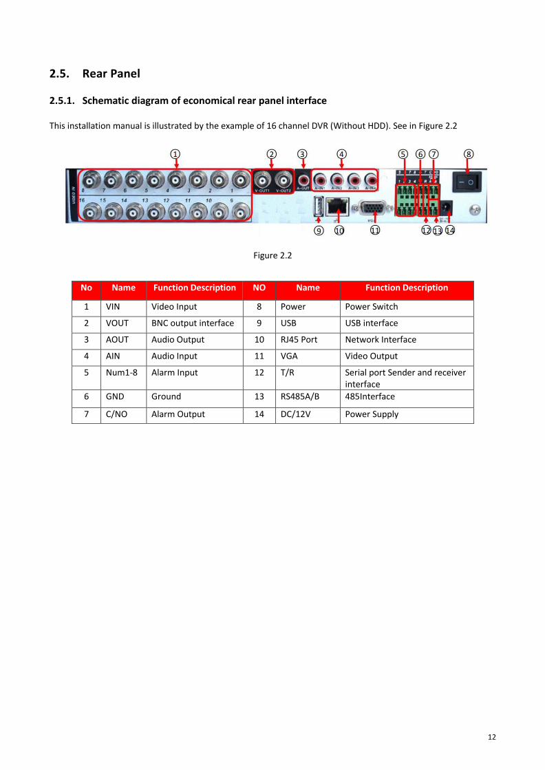
2.5. Rear Panel 2.5.1. Schematic diagram of economical rear panel interface This installation manual is illustrated by the example of 16 channel DVR (Without HDD). See in Figure 2.2
Figure 2.2
No Name Function Description NO Name Function Description
1 VIN Video Input 8 Power Power Switch
2 VOUT BNC output interface 9 USB USB interface
3 AOUT Audio Output 10 RJ45 Port Network Interface
4 AIN Audio Input 11 VGA Video Output
5 Num1-8 Alarm Input 12 T/R Serial port Sender and receiver interface
6 GND Ground 13 RS485A/B 485Interface
7 C/NO Alarm Output 14 DC/12V Power Supply

13
2.6. Audio/Video Input and Out Connections 2.6.1. Video Input DVR (WITHOUT HDD) video input port to the BNC input signal requirements: PAL / NTSC BNC (1.0VP-P, 75Ω).
Video signal should comply with national standards, a higher signal to noise ratio, low distortion, low interference,
image must be clear, invisible change, real and natural color, brightness is appropriate.
Ensure stable and reliable camera signal:
Cameras should be installed in a suitable location, to avoid backlighting, low light conditions, or the use of good
results backlight compensation cameras, low-light cameras. Camera and DVR (WITHOUT HDD) power supply should
be common ground, and reliable, in order to ensure the normal operation of the camera.
Ensure stable and reliable transmission line:
Using high-quality, shielded coaxial good video, and based on the transmission distance to choose the right
model. If the distance is too far, should be based on the specific circumstances, the use of twisted pair, add
video compensation equipment, fiber optic transmission and other ways to ensure signal quality.
Video signal line should avoid strong electromagnetic interference to other equipment and lines, especially should
avoid high-voltage current string into.
Lugs ensure good contact:
Signal and shield lines should be firm, well-connected, avoid Weld, lap welding, to avoid oxidation.
2.6.2. Select and Connect the Video Output Device Video output is divided into PAL / NTSC BNC (1.0VP-P, 75Ω) output and VGA output (VGA is optional) Choose
to use computer to replace the monitor should pay attention to the following questions:
• Do not keep long boot state to extend the life of the equipment;
• Regular degaussing, which will help maintain the normal operation of the display?
• Away from strong electromagnetic interference devices.
Use TV as a video output device is an unreliable alternative. It also requires minimizing the use of time and
strictly controls the interference power caused by neighboring devices. Inferior TV leakage risks may cause
damage to other equipment.
2.6.3. Audio input BNC connector (only one to support intercom function) Audio input impedance is high, and therefore must be used
active pickups. Similar to the video input audio transmission requires line to avoid interference, avoid Weld, poor
contact, and special attention to prevent a string of high-voltage current into.

14
2.6.4. Audio output Audio output signal parameters is generally greater than 200mv 1KΩ (BNC), user can directly connect the low
impedance headphones, powered speakers or other sound through power amplifier output devices. In the case of
external speakers and microphone cannot be achieved spatial isolation, it is easy to produce output howling
phenomenon. At this point the measures to be taken are:
• The use of directional better pickups.
• Adjust speaker volume, making it lower than the threshold to produce the whistle.
• Multi-use environment using sound-absorbing materials decoration, reduce the reflection of the
sound, improve the acoustic environment.
• Adjust the layout of pickups and speakers, but also can reduce the occurrence of howling situations.
2.7. Alarm input and output connections Before connecting the device, please note the following:
* Note: Some Series devices doesn’t support alarm input and output functions.
2.7.1. Alarm Input Alarm input is grounding alarm input. Alarm input requirements for ground voltage signal. When the alarms are
connected to two DVR (WITHOUT HDD) or simultaneously access the DVR (WITHOUT HDD) or DVR (WITHOUT HDD)
and other devices, need to be isolated by relay.
2.7.2. Alarm Output DVR (WITHOUT HDD) alarm output cannot be connected power load (no more than 1A), should constitute the
output loop current is too large to prevent damage to the relay. Require the use of high-power load contactors
isolation.
2.7.3. PTZ Decoder connected • Must do PTZ decoder and DVR (WITHOUT HDD) common ground, otherwise there may be Common-mode
voltage will lead to control PTZ. Recommended to use shielded twisted pair with shielding for common
ground connection.
• Prevent high voltage in series, rational layout, and good lightning protection measures.
• To be incorporated into the 120-ohm resistor in the remote reduced reflection, to ensure signal quality.
• DVR (WITHOUT HDD) 485 AB line cannot be connected with other 485 output.
• AB line voltage between the decoder requires less than 5V.
2.7.4. Front-end device requires grounding Poor grounding may cause the chip to burn.

15
2.7.5. Any type of alarm input The alarm output unit interface is a normally open type.
8 external alarm interface schematics:
1) Alarm input 1,2,3,4
2) Ground
3) RS232 serial interface to send and receive
4) RS485 interface
5) Alarm inputs 5,6,7,8
6) Ground
7) Alarm output
16 External alarm interface schematics:
① ⑥⑧ alarm input ②⑦ ground ③ alarm output RS485④RS232

16
Parameters Meaning
G GND
R, T Send and receive serial interface
A, B 485 communication interface
2.7.6. Alarm Input Port Description Please refer to the following sheer for more information.
• Grounding alarm inputs. (Normal open or Normal close type)
• Please parallel connect COM end and GND end of the alarm detector (Provide external power to the
alarm detector).
• Please parallel connect the ground of the DVR (WITHOUT HDD) and the ground of the alarm detector.
• Please connect the NC port of the alarm sensor to the DVR (WITHOUT HDD) alarm input (ALARM).
• Use the same ground with that of DVR (WITHOUT HDD) if user use external power to the alarm device.
2.7.7. Alarm Output Port Description • Provide external power to external alarm device.
• To avoid overloading, please read the following relay parameters sheet carefully.
• RS485 A/B cable is for A/B of the PTZ decoder.
• T+, T-, R+, R- are four-wire double duplex RS485 port.
T+ T-: Output wire
R+ R-: Input Wire
2.7.8. Alarm output Relay terminal parameters
Model: JRC-27F
Shock material Silver
Ratings
(Resistive load)
Rated switching capacity 30VDC 2A, 125VAC 1A
Maximum switching power 125VA 160W
Maximum switching voltage 250VAC, 220VDC

17
Maximum switching current 1A
Insulation
between the same polarity Contacts 1000VAC 1 minute
between different polarity Contacts 1000VAC 1 minute
Between coil and contacts 1000VAC 1 minute
Surge voltage between the same polarity Contacts 1500VAC (10×160us)
Opening time 3ms max
Turn-off time 3ms max
Lifetime Machinery 50×106 MIN(3Hz)
Electrical 200×103 MIN (0.5Hz)
Work environment -40~+70℃

18
2.7.9. Connect Line 485 When the DVR (WITHOUT HDD) receives a camera control command, it transmits that command up the coaxial
cable to the PTZ device. RS485 is a single-direction protocol; the PTZ device can’t return any data to the unit. To
enable the operation, connect the PTZ device to the RS485 (A, B) input on the DVR (WITHOUT HDD). Since RS485
is disabled by default for each camera, user must enable the PTZ settings first. This series DVR (WITHOUT HDD)
support multiple protocols such as Pelco-D, Pelco-P.
To connect PTZ devices to the DVR (WITHOUT HDD):
• Connect RS485 A, B on the DVR (WITHOUT HDD) rear panel.
• Connect the other end of the cable to the proper pins in the connector on the camera.
• Please follow the instructions to configure a camera to enable each PTZ device on the DVR (WITHOUT
HDD)
8 external alarm 485 Schematic
16 external alarm 485 Schematic

19
2.8. Other Interface There are other interfaces on the DVR (WITHOUT HDD), such as USB Ports.

20
3. Basic Operations 3.1. Turn On Plug the power supply and turn on the power supply switch. Power supply indicator light shining indicates turning
on the video recorder. After the start-up user will hear a beep sound. The default setting of video output is
multiple-window output mode. If the start-up time is within the video setting time, the timing video recording
functions will start-up automatically. Then the video indicator light of corresponding channel is shining and the DVR
(WITHOUT HDD) is working normally.
Note:
• Make sure that the input voltage corresponds with the switch of the DVR (WITHOUT HDD) power supply.
• Power supply demands: 220V±10% /50Hz.
• Suggest using the UPS to protect the power supply under allowable conditions.
3.2. Turn Off There are two methods to turn off the DVR (WITHOUT HDD). Entering [Main Menu] and choosing [Shutdown] in
the [Turn off the system] option is called soft switch. Pressing the power supply switch is called hard switch.
Illumination:
• Auto resume after power failure
If the DVR (WITHOUT HDD) is shut down abnormally, it can automatically backup video and resume previous
working status after power failure.
• Replace the hard disk
Before replacing the hard disk, the power supply switch in the real panel must be turned off.
• Replace the battery
Before replacing the battery, the setting information must be saved and the power supply switch in the real panel
must be turned off. The DVR (WITHOUT HDD) uses button battery. The system time must be checked regularly. If the
time is not correct user must replace the battery, we recommend replacing the battery every year and using the
same battery type.
Note: The setting information must be saved before replacing the battery otherwise information will lose.
3.3. System Login
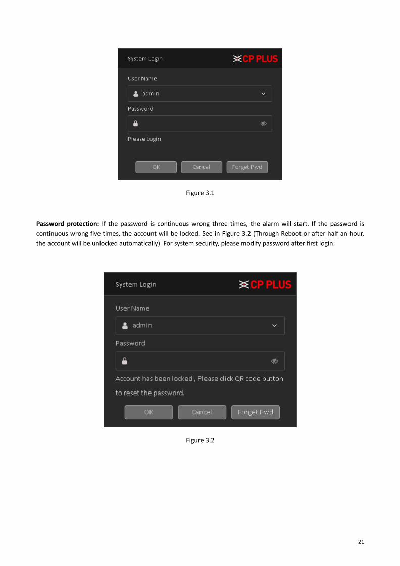
When the DVR (WITHOUT HDD) boots up, the user must login and the system provides the corresponding functions with the user preview. There are two user settings - The names are admin, and default. Admin is the super user preview; default’s Permissions are preview and video playback. User password can be revised, while their permissions can’t be revised; user default is the default login user whose permission can be revised but not its password. See in Figure 3.1.
21
Figure 3.1
Password protection: If the password is continuous wrong three times, the alarm will start. If the password is
continuous wrong five times, the account will be locked. See in Figure 3.2 (Through Reboot or after half an hour,
the account will be unlocked automatically). For system security, please modify password after first login.
Figure 3.2

22
3.4. Device Initialization / Forget Password 3.4.1. Device Initialization When booting up for the first time, user need to configure the password information for admin (by default).
To secure the Device, it is strongly recommended for user to properly keep the password for admin and modify it
regularly.
✓ Turn on the Device. The Device Initialization interface is displayed. See Figure 3.3
Figure 3.3
✓ Configure the password information for admin.
Parameter Description
User By default, the user is admin.
Password
In the Password box, enter the password for admin. The new password can be set from 8 characters through 32 characters and contain at least two types from number, letter and special characters (excluding"'", """, ";", ":" and "&").
Confirm Password

23
✓ Click Next. ✓ Draw a unlock pattern.
The unlock pattern setting interface is displayed. See Figure 3.4.
Figure 3.4
✓ Confirm the pattern, as display in Figure 3.5
Figure 3.5

24
After pattern configuration is completed, it will show the prompt. See Figure 3.6.
Figure 3.6
• The pattern that user wants to set must cross at least four points.
• If user do not want to configure the unlock pattern, click Skip.
• Once user have configured the unlock pattern, the system will require the unlock pattern as the default
login method. If user skip this setting, enter the password for login.
✓ Setup Email and Security Question to reset password.
Configure Email and Security Question to reset password. After configuration, if user forgot the password for
admin user, user can reset the password through the reserved email address or security questions. For details
about resetting the password, see "Forget Password" If user do not want to configure the settings, disable the
email address and security questions functions on the interface.
Figure 3.7

25
Password Protection
Mode Description
Email Address
Enter the reserved email address.
In the Email Address box, enter an email address for password reset.
In case user forgot password, enter the security code that user will
get from this reserved email address to reset the password of admin.
Security Questions
Configure the security questions and answers.
In case user forgot password, enter the answers to the questions can
make user reset the password.
If user want to configure the email or security questions fucntion later or user want to change
the configurations, select Main Menu → Account → Select User → Forget Pwd
✓ Click Save to complete the settings.
After setup Device initialization, Startup Wizard is displayed for details about quick settings during startup, see "

26
Start-up Wizard"
3.4.2. Forget Password User can reset the password through the QR code or the security questions.
• To reset through the QR code.
• To reset through the security questions, make sure the security quesitons is configured.
✓ Enter the login interface.
If user have configured unlock pattern, the unlock pattern login interface is displayed. See Figure 3.8. Click Forgot
Pattern, the password login interface is displayed. See Figure 3.9.
If user did not configure unlock pattern, the password login interface is displayed. See Figure 3.9.
On the unlock pattern login interface, click Switch User to login, or on the password login interface, in the User
Name list, select other users to login.
Figure 3.8

27
Figure 3.9
✓ Click , at login page.
If user did not set the reserved email address, then user will get a QR code without email ID. See Figure 3.10. Need to scan QR code from QR code scanner app, user will get a string and please send complete string or proper picture of QR code on [email protected] user will get the password within 24 hr. of working days.
Figure 3.10
If user have set the reserved email address, the Reset the password interface is displayed. See Figure 3.11.

28
Figure 3.11
✓ Rest the password. ➢ QR Code
Follow the onscreen instructions to get the security code in reserved email address. In the Security code box,
enter the security code.
User are given the limited times to get the security code by scanning the QR code within 24 hours. Please operate
carefully.
Please use the security code received in email box to reset the password within 24 hours, otherwise the security
code becomes invalid.
➢ Security Questions
On the Reset the password interface as shown in Figure 3.11, in the Reset Type list, select Security Questions, the
Security Questions interface is displayed, see Figure 3.12.
If user did not configure the security questions before, in the Reset Type list, there will be no Security Questions.
In the Answer box, enter the correct answers.

29
Figure 3.12
✓ Click Next
The new password resetting interface is displayed. See Figure 3.13
Figure 3.13
✓ In the Modify Password box, enter the new password and enter it again in the Confirm Password box. ✓ Click OK. The password resetting is started. After resetting is completed, a pop-up message is displayed.
See in Figure 3.14.

30
Figure 3.14

31
3.5. Start-up Wizard After device successfully booted up, it goes to startup wizard. See Figure 3.15, Click Cancel/Next button, user can
see system goes to login interface.
Tips
Check the box Startup button here, system goes to startup wizard again when it boots up the next time. Cancel
the Startup button, system goes to the login interface directly when it boots up the next time.
Figure 3.15
Click Cancel button or Next Step button, system goes to login through pattern interface or user can login through
User and Password interface by clicking on Switch User. See Figure 3.16.
Figure 3.16

32
Caution
⚫ Continuous five times login failure will result in account lock!
⚫ Please reboot the device or wait for 30 minutes to try again if account has been locked.
After input corresponding user name and password, user can click OK button. System goes to the startup wizard.
• When there are all analog channels, the startup wizard includes Date n Time and language, Network Test and
Install Mobile App.
➢ Click OK button, user can go to General interface. See Figure 3.17.
For detailed information, please refer to chapter 4.1.5.1.
Figure 3.17
➢ Click on Next button, user will go to Network test page. See Figure 3.18
Figure 3.18

33
➢ Click on Next button, now user will go to install mobile app. See Figure 3.19. Here user will get QR code
link to redirect mobile application for android and IOS base. And also, user will get QR code to get serial
No. of device for InstaOn.
Figure 3.19
➢ Click Next button, system pops up a dialogue box. Click the OK button, the startup wizard is complete. See
Figure 3.20
Figure 3.20
3.6. Preview User can right click mouse to choose the switch between the windows. The system date, time and channel name
are shown in each viewing window. The surveillance video and the alarm status are shown in each window.

34
1
Recording status 3
Video loss
2
Motion detection 4
Camera lock
➢ Use mouse middle scroll wheel to change channel No: User can use mouse middle scroll wheel to switch
channel to another channel.
➢ Digital Zoom - It is to zoom in specified zone of current channel. Please drag mouse with left click to
select a zone and then click in selected zone. user can view an interface show as Figure 3.21
Figure 3.21
➢ MIC Sound - If user have connected a MIC with device and want to get the sound of audio input than
please click on the same channel to get audio and to disable audio please click on .
➢ Signal Mode – To change camera signal mode please click on of particular channel window, by
clicking this icon it will change channel signal mode like TVI, AHD, CVI and AUTO.

35
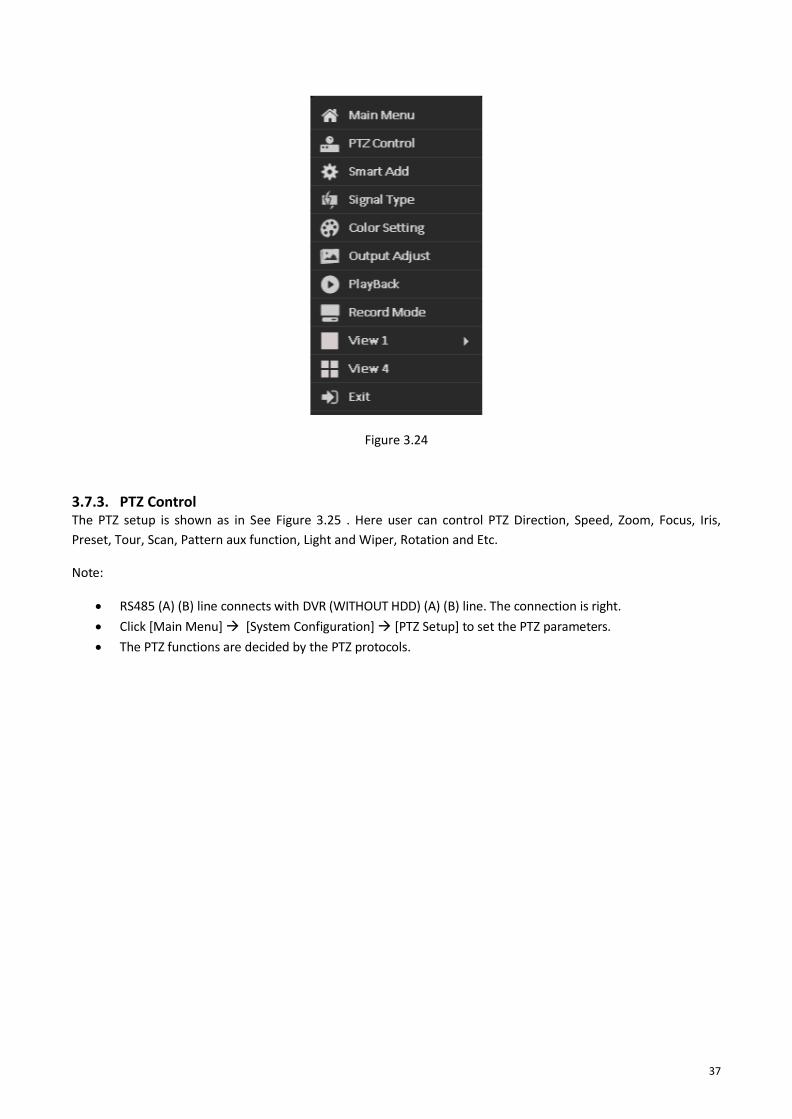
3.7. Right Click Menu In preview mode user can right click mouse to get a drop-down menu, as in Figure 3.22. The menu includes:
Main Menu, PTZ Control, Smart Add, Signal Type, Color Setting, Output Adjust, Playback, Record Mode,
Window Split Mode and Exit.
Figure 3.22
36
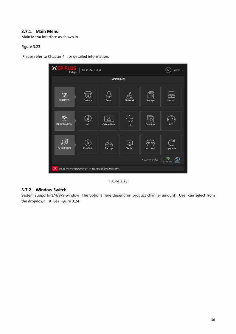
3.7.1. Main Menu Main Menu interface as shown in
Figure 3.23
Please refer to Chapter 4 for detailed information.
Figure 3.23
3.7.2. Window Switch System supports 1/4/8/9-window (The options here depend on product channel amount). User can select from
the dropdown list. See Figure 3.24
37
Figure 3.24
3.7.3. PTZ Control The PTZ setup is shown as in See Figure 3.25 . Here user can control PTZ Direction, Speed, Zoom, Focus, Iris,
Preset, Tour, Scan, Pattern aux function, Light and Wiper, Rotation and Etc.
Note:
• RS485 (A) (B) line connects with DVR (WITHOUT HDD) (A) (B) line. The connection is right.
• Click [Main Menu] → [System Configuration] → [PTZ Setup] to set the PTZ parameters.
• The PTZ functions are decided by the PTZ protocols.

38
Figure 3.25
➢ [Speed] Speed is to control PTZ movement speed. The value ranges from 1 to 8. The speed 8 is faster than
speed 1, default value will be 5.
➢ [Hide] Current interface will be temporarily hidden after clicking it.
➢ [Control] Control the PTZ rotation, 8 directions are supportive. If user is using direction buttons on the
front panel, there are only four directions: up/down/left/right.
➢ [Zoom] Click / to adjust the zoom IN or OUT.
➢ [Iris] Click / to adjust Iris Value.
➢ [Focus] Click / to adjust camera Focus.
➢ [Smart PTZ] Full-Screen show channel image. Left press mouse and control PTZ to rotate orientation. Left
press mouse and then rotate the mouse to adjust the zoom Multiple of the camera.

39
Special Functions: -
• [Set Preset] Preset is a specific spot user can focus PTZ's view on and assign it a number. By activating the
preset number camera will go to the exact spot user specified. It can also be used with the other options
such as Tour.
To set a Preset, procedure is as follows:
a. Move PTZ through direction keys to a selective location.
b. Enter preset no. in and then click on .
c. By above procedure user can create No. of preset.
To Delete a Preset Procedure is as follows:
a. Enter a preset No. in which user want to delete.
b. Then click on to delete particular Preset.
c. User can only delete one preset at a time.
To call a Preset, procedure is as follows:
a. Enter a preset No. in which user want to call.
b. Then Click on , PTZ will turn to preset position.
c. User can call only one preset at a time.
• [Advanced] To enter a new operation page as shown in Figure 3.26
Figure 3.26

40
• [Set Tour] Tour is the collection of preset, which call automatically one by one according to their prefix
order.
To set tour, procedure as follow-
a. Enter a tour No. in and then click on .
b. Now in tour window, select predefine preset which user want to add in tour.
c. Input Tour interval, in . It is time duration gap to call next preset.
d. Click on button to add selected preset in tour. It will show in Exist Preset, See Figure
3.27
Figure 3.27
e. To delete added preset from tour, please select particular tour in Exist Preset and click on .
To delete a tour Procedure is as follows:
a. Enter a Tour No. in which user want to delete.
b. Then click on to delete particular tour. See Figure 3.26
c. User can only delete one tour at a time.
To call a Tour, procedure is as follows:
a. Select tour No. in which user want to call.
b. Then Click on , PTZ will turn to preset position. See Figure 3.26
c. User can call only one preset at a time.

41
• [Pattern] A pattern is similar to a preset but instead of one fixed view assigned to a number user are able
to move/zoom the camera for an allotted percentage that lowers the more user adjust it. User can also
assign each pattern user create a number.
To set pattern, procedure as follow-
a. Enter a patter No. in and then click on .
b. Now in pattern window, rotate PTZ to desirable location and path.
c. Click on button to save followed path as pattern. See Figure 3.28
Figure 3.28
To delete a pattern Procedure is as follows:
a. Enter a pattern No. in which user want to delete.
b. Then click on to delete particular pattern. See Figure 3.26.
c. User can only delete one pattern at a time.
To call a Tour, procedure is as follows:
a. Select Pattern No. in which user want to call.
b. Then Click on , PTZ will start follow pattern path. See Figure 3.26.
c. User can call only one preset at a time.

42
• [Auto Pan] This feature consistently rotates the camera in 360° movement.
To start and stop Auto Pan Procedure is as follow:
a. Click on ; PTZ will start rotating in 360°.
b. To stop Auto Pan, click on button. See Figure 3.29
Figure 3.29
• [Auto Scan] Auto scan consistently pans between a left border and a right border that user set until
turned off. Keep in mind that the left border is the starting position and this feature only goes left to right
and continually scans between them, it will not go from the left point to a right point that is positioned
lower or higher than the initial point user set the left border at.
To set Auto Scan, procedure as follow-
a. Use direction key to rotate PTZ camera to set left limit and then click on .
b. Use again direction key to set PTZ camera Right limit and then click on .
To start and stop Auto Scan Procedure is as follow:
a. Click on ; PTZ will start rotating in 360°.

43
b. To stop Auto Pan, click on button. See Figure 3.30
Figure 3.30
• [Flip] Rotates the camera 180°.
• [Reset] Resets the camera to its default point.
➢ [Page Switch] To enter and configure PTZ camera OSD menu options. See Error! Reference source not
found.
Figure 3.31

44
3.7.4. Smart Add Shortcut to add IP camera in DVR (WITHOUT HDD), it automatically searches all IP camera in network and auto
add in device as per DVR (WITHOUT HDD) DAC mode. See Figure 3.32
Figure 3.32
3.7.5. Signal Type Select signal type to get camera video according to camera signal. Like (HDCVI, HDTVI, AHD and CVBS) or can
select auto option to get type signal automatically. See Figure 3.33

45
Figure 3.33
3.7.6. Color Setting Set selected channel color setting (single-screen preview of the current channel or select channel window of
particular camera color setting include: Brightness, Contrast, Saturation, Hue, Gain, Horizontal sharpness, Vertical
sharpness. And according to the needs of different image parameters set in two different time periods. See Figure
3.34
Figure 3.34
3.7.7. Output Adjustment Adjust output area parameters and output display interface color setting for VGA and HDMI. Output Adjust include:
Top Deflate, Bottom Deflate, Left Deflate, Right Deflate, Black Vertical and Black Horizontal including Brightness,
Contrast, Saturation and Hue of VGA/HDMI display settings adjustment. See Figure 3.35
Figure 3.35

46
3.7.8. Playback Check Recorded video backup of cameras. See Figure 3.36. Please refer to chapter 4.3.1 for detailed information.
Figure 3.36
3.7.9. Record Mode
Please check current channel status: means it is not in recording status, and means it is in recording
status. See Figure 3.37.

47
Figure 3.37
✓ Main Stream
o [Schedule] Channel records main Stream as user have set schedule time. Please refer to chapter
4.1.4.1 for detailed information.
o [Manual] The highest priority, after manual setup, all selected channels will begin ordinary
recording for main stream.
o [Stop] Current channel stops recording.
✓ Extra Stream
o [Schedule] Channel records extra Stream as user have set schedule time.
o [Manual] The highest priority, after manual setup, all selected channels will begin ordinary
recording for extra Stream.
o [Stop] Current channel stops recording.
✓ Snapshot
o [Enable] Channel captures snapshot as user have set schedule time.
o [Disable] Stop capturing channels Snapshot.
✓ [All] Check all buttons after the corresponding status to enable/disable all-channel schedule/manual
record or enable/disable all channels to stop record.
3.7.10. Exit Logout or Reboot the system. User can use the desktop shortcut menu or enter [Main Menu]. See Figure 3.38
Figure 3.38

48
4. Main Menu The Main Menu interface is shown as below. See Figure 4.1.
Figure 4.1
4.1. Settings 4.1.1. Camera
Encode When the product is set to DAC mode / full analog channel mode, the system will be set up in the encoding setting
function, encoding settings can only function in an analog channel encoding settings.
Set the video / audio encoding parameters including video files, remote monitoring and other image parameters.
The left part of each individual channel set encoding parameters, the parameters set on the right part of the
secondary stream, dual-stream uses 1080P / 1080N / 720P / 960H / D1 / HD1 / CIF / QCIF encoding rate of the
stream all the way to high definition for local storage, support all the way to low bit rate stream (QCIF coding) for
network transmission, taking into account local storage and remote network transmission. Dual-stream network
bottlenecks in the existing balance between image quality and transmission quality, can break through the
bottleneck of the network, the flexibility to select the format according to the network bandwidth stream, to local
HD storage, while the rear end of the transmission of low stream networks.

49
Note: Basic purpose of the sub stream is for multi-channel real-time monitoring, mobile monitoring under
poor network.
• [Channel] Select the channel user want.
• [Compression] System supports H.264 ➢ H.265: High Efficiency Video Coding (HEVC), also known as H.265 and MPEG-H Part 2, is a video
compression standard, designed as a successor to the widely used AVC (H.264 or MPEG-4 Part 10) ➢ H.264: It is the High-Profile compression algorithm. It has the high encode compression rate. It can
achieve high quality encode at low bit stream.
• [Resolution] For analog channel, system supports various resolutions, user can select from the dropdown list. Please note the option may vary due to different series. For digital channel, the resolution here refers to the capability of the network camera.
• [Frame Rate] It ranges from 1f/s to 25f/s. It depends on channel resolution.
• [Bit Rate Type] System supports two types: CBR and VBR. In VBR mode, user can set video quality.
• [Quality] There are six levels ranging from Lowest to Highest. The sixth level has the highest image quality.
• [I Frame Interval] Here user can set the P frame amount between two I frames. The value ranges from 1 to 12. Recommended value is 2.
• [Smart Codec] Enable the smart codec function. This function can reduce the video bit stream for non-important recorded video to maximize the storage space.
• [Video/audio] User can enable or disable the video/audio.
Figure 4.2

50
Snap Encode Snap Encode interface as shown in Figure 4.3.
Figure 4.3
Please refer below table to configure Snap encode parameter.
Parameter Description
Channel In the Channel list, select the channel that user want to configure the settings for.
Compression To set image compression, by default it set on MPEG
Image Size In the Image Size list, select a value for the image.
Channel Mode It is to set channel mode. Each mode support HD Analog/IP camera or only HD analog camera or Only IP Camera
(Slight function difference may be found). Please note DVR (WITHOUT HDD) needs to restart to activate new
mode. The interface is shown as in Figure 4.4

51
Figure 4.4
While selecting channel mode, in some mode custom option is available through which user can customize HD
analog or IP mode as per the channel.
✓ [Custom] enable custom option to choose particular channels for HD or IP.
✓ [No. of Channel] Select the total no. of channel as per custom channel mode.
✓ [Selection] Here to select particular channel for IP, by default all channels are selected on HD Analog
mode. So, user need to change channel type from last channel to first channel.

52
o Please click on to select as IP channel.
Note – Custom option is depending on Device Specification and channel mode. So slight differences, user may
find in their device.
Remark: Compatible four types of front-end camera: AHD, HD-TVI, HD-CVI and IPC. Among all analog channel,
every channel attribute mutual independence, inexistence the binding relationship of any channel.
Add IP Device Here user can add/delete IP device and view its corresponding information. Figure 4.5
Figure 4.5
✓ [IPC Filter] Select IP address or MAC Address and input particular IPC details and click on Search button.
✓ [Search] Click it to search IP address. It includes device Protocol, Device Info (MAC Address), IP address and
Port. Use mouse to click , user can refresh display order. Click IP address, system displays IP
address in ascending order. Click IP address again, user can see icon, system displays IP address in
Descending order. User can click other items to view information conveniently.
✓ [Add] Click it to connect to the selected device and add it to the Added device list.
✓ [Modify IP] Click it to modify IP address of Searched IP devices. Note – it only works with private protocol
devices.
✓ [Manual Add] Click it to add the IPC manually at custom level. See Figure 4.6

53
Figure 4.6
➢ [Channel] Select channel no.
➢ [Device Type] 3 types: IPC, DVR (WITHOUT HDD), And NVR. User can choose as what user like, default
is IPC.
➢ [IP Channel] User can input remote channel title from the device that user want to connect remotely.
➢ [Device Address] To enter Device IP Address. It supports only IPv4.
➢ [Protocol] There are two protocols Private and ONVIF, the default is Private.
➢ [Stream] Optional Main stream and Extra stream, the main stream by default.
➢ [Port] TCP port of remote device, by default is 25001.
➢ [User name] To input user name of remote device, by default is admin
➢ [Password] To input remote device password for selected user, by default is admin.
➢ [Connect] To establish the connection between DVR (WITHOUT HDD) and remote device.
➢ [Connection Mode] Can be singe connect or multi-ink, multi-link modes can connect to several
devices, device will be tour displayed one by one, tour interval can be set, no less then 10s.
➢ [Time Sync] To disable or select time synchronization mode with device and UTC.
➢ [Decode Order] To select mode of network video stream transmission. It includes: Real Time, Middle
and Fluency.
➢ [Synchronization Resolution] To enable resolution modification of network camera through DVR
(WITHOUT HDD) end.
✓ [Delete] Click it to delete existing device, if the user wants to change device. Select the existing device and
click on Delete.
✓ [Encode] To set encode setting of IPC. Please refer to Chapter 4.1.1.1 for detailed information.
• [ / ] To swift up or swift down added remote devices.

54
Double-click the discovered devices, click the button; user can just add the device to the network settings.
IP Camera Status Channel status is to show the status of the entire IPC channel when there is what existing, status including Max
Resolution, Current Resolution, and Connection Status. See Figure 4.7.
Figure 4.7
Channel Name It is to modify channel name. See Figure 4.8. Please note for digital channel, user can only modify the channel
name of the connected network camera.
Figure 4.8

55
Channel Overlay Channel Overlay interface is shown as in Figure 4.9.
Figure 4.9
• [Channel] To select the channel on which user want overlay.
• [Channel Overlay] To enable or disable overlay setup.
• [Setup] Here is for user to set cover area. User can drag user mouse to set proper section size. In one channel
video, system max supports 4 zones in one channel.
• [Zone] To select No. of zone for overlay on channel video.
Note – By default overlay will effect on both preview and monitor state, means after setup the channel overlay it
will be affected on live preview as well as in playback of same channel.
IPC Parameter IPC Parameter interface as shown in Figure 4.10.
Note – IPC parameter will work with only for that IPC which is connected with Private protocol.

56
Figure 4.10
• [Channel] Select a channel from the dropdown list. (Only those channels will show in dropdown list which
was added through private protocol).
• [Exposure Mode] To choose camera exposure as auto (0.1 millisecond – 80 millisecond) or manual (1/50,
1/120, 1/250, 1/500, 1/1000, 1/2000, 1/4000, 1/10000) default is auto.
• [AE Reference] To choose auto exposure integer data between 0 ~ 100, default value is 50.
• [Day/Night Mode] To choose Automatic, Color or Black and White mode.
• [IR Cut] To choose automatically to switch or IR synchronous switch, default is automatically.
• [Image Style] To set image style as per profile.
• [Profiles] To choose camera profile as per camera location, user can choose auto, indoor or outdoor. By
default, is auto.
• [ICR Threshold] To set IR-Cut filter threshold level, value range 10 to 50. By default, value is 30.
• [BLC] To enable or disable auto exposures according to the environment’s situation so that the darkest area
of the video is cleared.
• [AE Sensitivity] To set auto exposure sensitivity level, value range 1 to 10. By default, value is 5.
• [Auto Iris] To enable or disable auto Iris feature.
• [Automatic Gain] To enable or disable auto gain control of camera, user can also set the upper limit of AGC
from 0 to 100. Default value is 50.
• [WDR] For the WDR scene, this function can lower the high bright section and enhance the brightness of the
low bright section. So that user can view these two sections clearly at the same time. User can set upper limit
of WDR, value ranges from 0 to 100. Default value is 50.
• [Defogging] To enable or disable defogging mode of camera. User can also set the grade for defogging; value
ranges from 0 to 100. Default value is 50.
• [Corridor Mode] To enable or disable corridor mode of camera. This feature is depending of camera feature.
• [Slow Shutter] To choose No, weak, in or strong.

57
• [Day noise Level] To set noise level in day time, value range from 0 to 5. Default is 3.
• [Night noise Level] To set noise level in day time, value range from 0 to 5. Default is 3.
• [Mirroring] It is to switch video up and bottom limit. This function is disabled by default.
• [Anti-Flicker] To enable or disable anti-flicker in the fluorescent light.
• [Overturn] To enable or disable overturn.
• [IR Swap] To enable or disable IR in day or night.
Important Note – In Camera page add IP device, IP Camera status and IPC parameter option will show or hide
according channel mode.
4.1.2. Event Motion Detect
By analyzing the video image, when the system detects a mobile signal, motion detection alarm is initiated, and
the linkage functions. See Figure 4.11
Note: The front-end equipment and this equipment need to enable this feature. Advanced button same to the
right mouse button.
Motion detection function of mixed mode / full analog and digital channels are different: motion detection alarm
digital channels only to turn its function at the local end, the corresponding remote device connected to the end
of the channel will have motion detection feature is turned on, when the remote device side corresponding
channel has motion detection scene occurs, the local side will be able to achieve its alarm function, otherwise the
motion detection function cannot be achieved, while the analog channels open as long as the local end
manufacturing mobile phenomenon on the line.
Figure 4.11

58
• [Channel] Select the number of channels to be set, the default one channel to the network camera.
• [Enabled] To enable or disable Motion Detect on particular channel.
• [Sensitivity] according to the sensitivity level of the lowest, low, medium, high, very high, the highest six-
speed optional. By default, is Middle.
Note: where only in motion detection settings and only analog channels can set its sensitivity of mixed mode / full
analog mode.
✓ [Region] Click setup; enter the settings area is divided into 16X12 blocks, red area for motion detection
fortified area. The white area is undefended, Settings area. Hold down the left mouse button, draw
settings area. See Figure 4.12 (By default the entire area selected for monitoring area).
Note: Mixed mode / full motion detection in analog mode only regional settings, and only analog channels to set
their area.
Figure 4.12
✓ [Period] User can also set the alarm time from Monday to Sunday every day 4 time periods, other time
will not trigger motion detection alarm information. See Figure 4.13

59
Figure 4.13
✓ [Interval] between two alarms generate alarm information shortest time interval can be set between 0
and 600Sec.
✓ [Record channel] When an alarm is triggered, the camera starts recording, user need to open detection
recording.
✓ [Tour] Here user can enable tour function when alarm occurs. System one-window tour.
✓ [PTZ Activation] Here user can set PTZ movement when an alarm occurs. Such as go to preset, tour
&pattern when there is an alarm. Click “Setup” button, user can see an interface is shown as in Figure
4.14.
Note: PTZ Activation, user need [shortcut menu] → [PTZ Control], set the preset point, tour between points,
intervals and other parameters
Figure 4.14
• [Post Rec] After the alarm ends, the length of time to continue the local recording can be set between 10
and 300S.
• [Show Message] on the local host screen, pop-up dialog box prompts warning information.
60
• [Send Email] When an alarm is triggered, sends an alarm message to the specified mailbox, through SMTP
settings.
• [Buzzer] When an alarm occurs, the device sends a "Beep" sound long ring.
• [Write Log] Check the box here, system can record motion detect log.
• [FTP Upload] Expressed alarm occurs if the selected channel or video capture channel, the video file up to
an FTP server.
Note: Upload FTP, need to be set accordingly in the [Network Services].
• [Buzzer] When an alarm occurs, the device sends a "Beep" sound long ring.
• [Alarm Push]: when an alarm occurs, the device sends a push notification on mobile client.
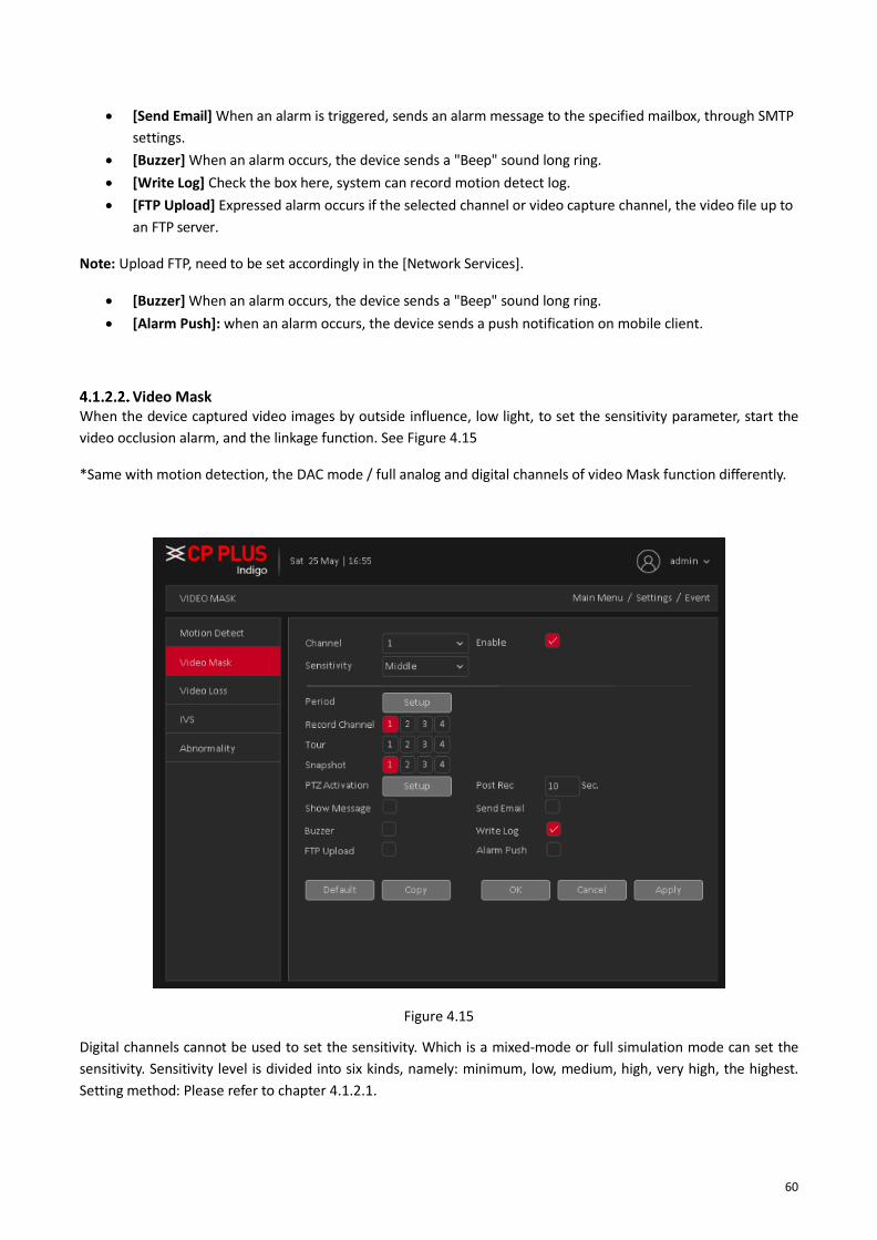
Video Mask When the device captured video images by outside influence, low light, to set the sensitivity parameter, start the
video occlusion alarm, and the linkage function. See Figure 4.15
*Same with motion detection, the DAC mode / full analog and digital channels of video Mask function differently.
Figure 4.15
Digital channels cannot be used to set the sensitivity. Which is a mixed-mode or full simulation mode can set the
sensitivity. Sensitivity level is divided into six kinds, namely: minimum, low, medium, high, very high, the highest.
Setting method: Please refer to chapter 4.1.2.1.
61
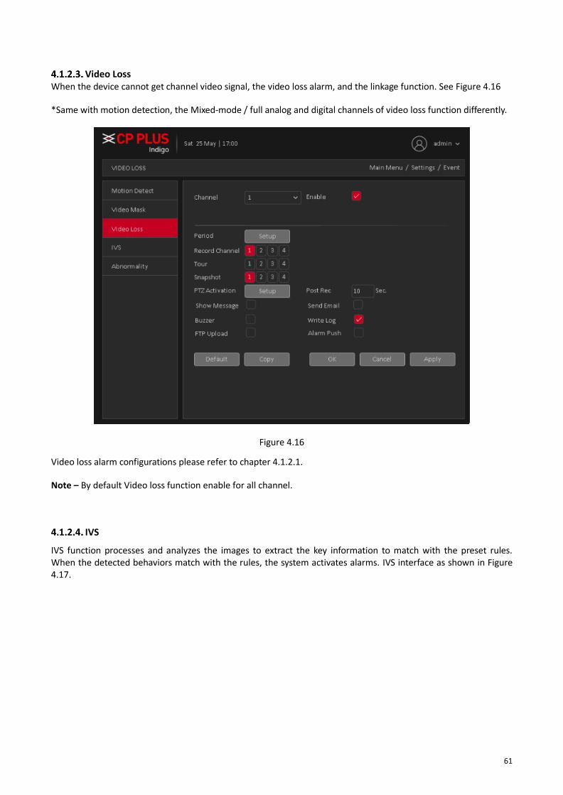
Video Loss When the device cannot get channel video signal, the video loss alarm, and the linkage function. See Figure 4.16
*Same with motion detection, the Mixed-mode / full analog and digital channels of video loss function differently.
Figure 4.16
Video loss alarm configurations please refer to chapter 4.1.2.1.
Note – By default Video loss function enable for all channel.
IVS
IVS function processes and analyzes the images to extract the key information to match with the preset rules. When the detected behaviors match with the rules, the system activates alarms. IVS interface as shown in Figure 4.17.

62
Figure 4.17
✓ Enable IVS and Select the channel for which user want to create IVS rule.
✓ [Show Traces] It will trace and mark the object with green color lines in real-time video, while object
passing through IVS rule.
✓ [Show rules] It will display IVS rule parameters in real-time video.
✓ [Algorithm] To select IVS rule, there are three in drop-down menu
✓ [Alarm Linkage] Interface as shown in Figure 4.18. When system detect any alarm by IVS rule, then user
can perform various activity through like Display tour, record Snapshot, Activate PTZ, Show message and
So on.

63
Figure 4.18
o [Period] User can also set the alarm time from Monday to Sunday every day 4 time periods,
other time will not trigger IVS alarm information. See Figure 4.19.
Figure 4.19

64
o [Interval] between two alarms generate alarm information shortest time interval can be set
between 0 and 600Sec.
o [Record channel] When an alarm is triggered, the camera starts recording, user need to open IVS
recording.
o [Tour] Here user can enable tour function when alarm occurs. System one-window tour.
o [PTZ Activation] Here user can set PTZ movement when an alarm occurs. Such as go to preset,
tour &pattern when there is an alarm. Click “Setup” button, user can see an interface is shown as
in Figure 4.20.
Note: PTZ Activation, user need [shortcut menu] → [PTZ Control], set the preset point, tour between points,
intervals and other parameters
Figure 4.20
o [Post Rec] After the alarm ends, the length of time to continue the local recording can be set
between 10 and 300S.
o [Show Message] on the local host screen, pop-up dialog box prompts warning information.
o [Send Email] When an alarm is triggered, sends an alarm message to the specified mailbox,
through SMTP settings.
o [Buzzer] When an alarm occurs, the device sends a "Beep" sound long ring.
o [Write Log] Check the box here, system can record motion detect log.
o [FTP Upload] Expressed alarm occurs if the selected channel or video capture channel, the video
file up to an FTP server.
Note: Upload FTP, need to be set accordingly in the [Network Services].
o [Buzzer] When an alarm occurs, the device sends a "Beep" sound long ring.
o [Alarm Push]: when an alarm occurs, the device sends a push notification on mobile client.
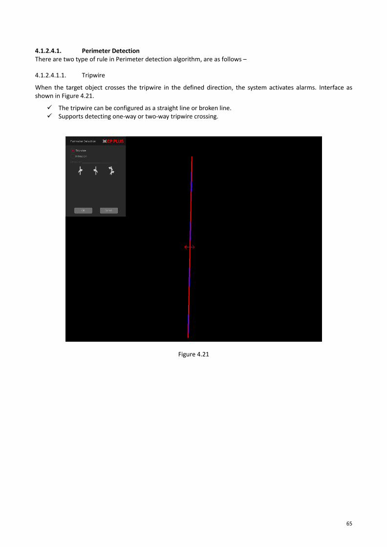
65
4.1.2.4.1. Perimeter Detection There are two type of rule in Perimeter detection algorithm, are as follows –
4.1.2.4.1.1. Tripwire
When the target object crosses the tripwire in the defined direction, the system activates alarms. Interface as shown in Figure 4.21.
✓ The tripwire can be configured as a straight line or broken line. ✓ Supports detecting one-way or two-way tripwire crossing.
Figure 4.21
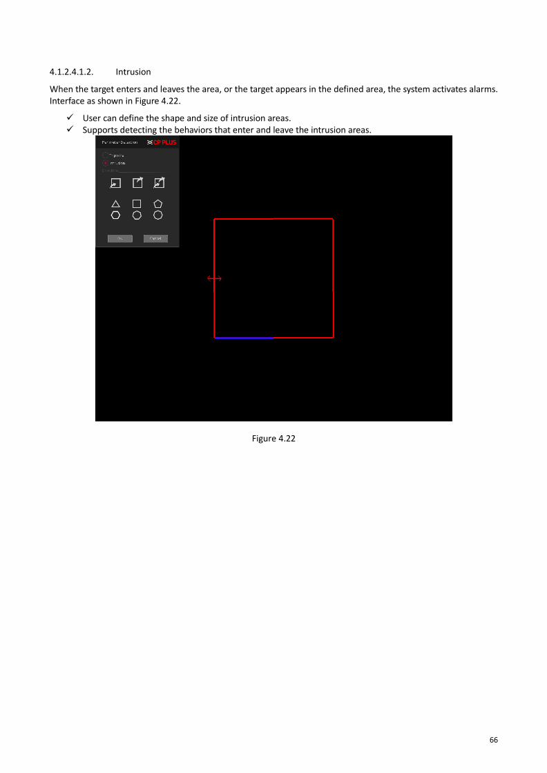
66
4.1.2.4.1.2. Intrusion
When the target enters and leaves the area, or the target appears in the defined area, the system activates alarms. Interface as shown in Figure 4.22.
✓ User can define the shape and size of intrusion areas. ✓ Supports detecting the behaviors that enter and leave the intrusion areas.
Figure 4.22

67
4.1.2.4.2. Missing/Abandoned Object There are two type of rule in Missing/Abandoned algorithm, are as follows –
4.1.2.4.2.1. Abandoned Object When the object is placed in the defined detection area for more than the set time, the system activates alarms.
Interface as shown in Figure 4.23
✓ User can define the shape and size of intrusion areas.
Figure 4.23

68
4.1.2.4.2.2. Missing Object When the target is taken away from the defined area exceeds the set time, the system activates alarms. Interface
as shown in Figure 4.24.
✓ User can define the shape and size of intrusion areas.
Figure 4.24
4.1.2.4.3. Scene Change When someone tramper camera mounting or change camera face, then system activates alarm. Interface as
shown in Figure 4.25.
Figure 4.25
✓ [Sensitivity] To set sensitivity level for scene change detection, user can select Higher, Middle or Lower.
✓ [Scene Change Detection] To enable Scene change detection.

69
Abnormality Some current hardware and software analysis and detection equipment, and when there is an abnormal event is
detected, the device responds accordingly, for example, the screen tips, buzzer, Alarm Push, Send Email, etc. See
Figure 4.26
Figure 4.26
• [Event Type] in the drop-down box to select the detection of abnormal like – No Disk, Disk Error, Disk No
Space, Net Disconnection, IP Conflict.
• [Enable] Means open the exception handling feature.
• [Show Message] On the local host screen, pop-up dialog box prompts warning information.
• [Buzzer] when an alarm occurs, the device sends a "Beep" sound long ring.
• [Alarm Push]: when an alarm occurs, the device sends a push notification on mobile client.
• [Send Email]: When an alarm is triggered, sends an alarm message to the specified mailbox, through SMTP
setting.
• [Auto Reboot] Device will reboot automatically.

70
4.1.3. Network TCP/IP
The single network adapter interface is shown as in Figure 4.27
Figure 4.27
• [Net Card] To select Network connection mode Wired or wireless. By default, is Wired NIC.
• [DHCP Enable] The Device is connected to the router which DHCP is open, then device will automatically
obtain an IP address. By default, DHCP enable.
• [IP Address] The IP address of the device is used to login network, the default is: 192.168.1.240.
• [Subnet Mask] Set the device's subnet mask, to be consistent with the login computer, default is
255.255.255.0.
• [Gateway]: Set the default gateway of the device, to be consistent with the login computer, the default is
192.168.1.1.
• [DNS Server]: Set the device's DNS server, to be consistent with the login computer.
• [TCP port]: Set the camera's TCP port, the default port is: 25001.
• [HTTP port]: Set the device's HTTP port, the default port is: 80.
• [LAN Download] System can process the downloaded data first if user enable this function. The
download speed is 1.5X or 2.0X of the normal speed.
• [Transfer Mode] Set the network transmission strategies, Adaptive / Quality Preferred/ Fluency
Preferred.
• [Network Encryption] An encrypted platform to access DVR (WITHOUT HDD) through remote login.
• [RTSP] Set the device's RTSP port, the default port is: 554.
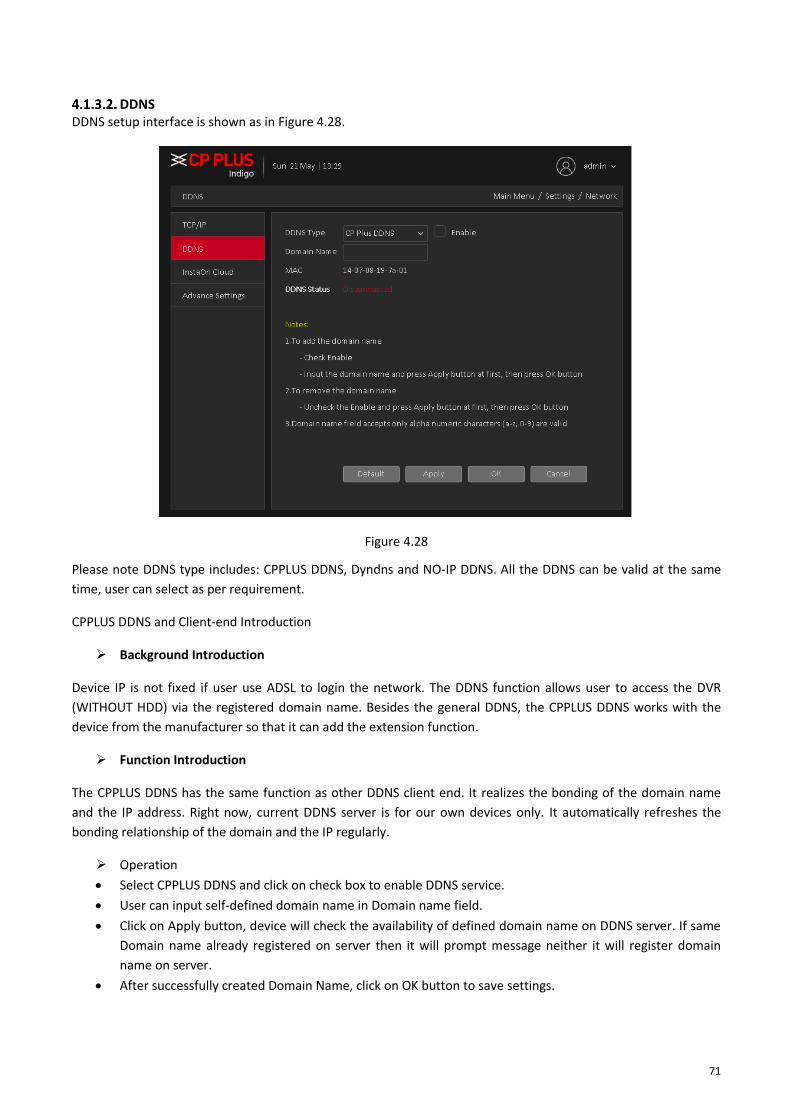
71
DDNS DDNS setup interface is shown as in Figure 4.28.
Figure 4.28
Please note DDNS type includes: CPPLUS DDNS, Dyndns and NO-IP DDNS. All the DDNS can be valid at the same
time, user can select as per requirement.
CPPLUS DDNS and Client-end Introduction
➢ Background Introduction
Device IP is not fixed if user use ADSL to login the network. The DDNS function allows user to access the DVR
(WITHOUT HDD) via the registered domain name. Besides the general DDNS, the CPPLUS DDNS works with the
device from the manufacturer so that it can add the extension function.
➢ Function Introduction
The CPPLUS DDNS has the same function as other DDNS client end. It realizes the bonding of the domain name
and the IP address. Right now, current DDNS server is for our own devices only. It automatically refreshes the
bonding relationship of the domain and the IP regularly.
➢ Operation
• Select CPPLUS DDNS and click on check box to enable DDNS service.
• User can input self-defined domain name in Domain name field.
• Click on Apply button, device will check the availability of defined domain name on DDNS server. If same
Domain name already registered on server then it will prompt message neither it will register domain
name on server.
• After successfully created Domain Name, click on OK button to save settings.

72
Important - Do not register frequently. The interval between two registrations shall be more than 60 seconds. Too
many registration requests may result in server attack.
InstaOn Cloud User can use cell phone to scan the QR code to get download link of cMOB application for iPhone & Android, and
also to get serial no. to add on mobile phone. See Figure 4.29
Via the SN from scanning the QR code, user can access the device in the WAN. Please refer to the InstaOn
operation manual included in the resources CD.
Figure 4.29

73
Advance Settings To Configure PPPoE, NTP, Email, IP Filter, FTP, Alarm Center, 3G, UPnP, WIFI, Alarm Push and HMS. See Figure
4.30
Figure 4.30
4.1.3.4.1. PPPoE PPPoE interface is shown as in Figure 4.31.
Figure 4.31
➢ To Enable disable PPPoE.
➢ Input “User Name” and “Password” user get from ISP (Internet service provider).
➢ Click save button, user need to restart to activate configuration.

74
➢ After rebooting, DVR (WITHOUT HDD) will connect to internet automatically. The IP in the PPPoE is the
DVR (WITHOUT HDD) dynamic value. User can access this IP to access DVR (WITHOUT HDD) from WAN
network.
4.1.3.4.2. NTP PPPoE interface is shown as in Figure 4.32
Figure 4.32
➢ [Enable] To enable or disable NTP Service.
➢ [Server IP] Input NTP Server IP address.
➢ [Port] The default NTP port 123, the port settings can be based on actual NTP server.
➢ [Update Period] NTP server check interval, the default is 60 minutes.
4.1.3.4.3. Email Set the e-mail addresses for DVR (WITHOUT HDD) sent and received alarm alert information. Email interface is
shown as in Figure 4.33.
Figure 4.33

75
➢ [Enable] To enable or disable email service.
➢ [SMTP Server] Input Email SMTP Server address.
➢ [Port] Input SMTP server service port number.
➢ [Encryption] To select connection encryption mode like SSL or TLS. By default, it none.
➢ [User Name] Input the user name of sender Email Box.
➢ [Password] Input the Password for the user name of sender Email Box.
➢ [Sender] Input the sender EMAIL address.
➢ [Receiver] User can set up to three e-mail address, separated by a semicolon, can outbox the same e-mail
address.
➢ [Title] Subject of the message, user can set own.
➢ [Test Mail] Click here to verify above setting.
4.1.3.4.4. IP Filter IP filter interface is shown as in Figure 4.34. User can add IP in the following list. System supports valid address of
IPv4 only. After user enabled Whitelist function, only the IP listed below can access current DVR (WITHOUT HDD).
If user enable Blacklist function, the following listed IP addresses cannot access current DVR (WITHOUT HDD).
Figure 4.34
• [Enable] Highlight the box here, user can check the trusted site function and blocked sites function. User cannot see these two modes if the Enable button is grey.
• [Type] User can select Whitelist or Blacklist from the dropdown list. User can view the IP address on the following column.

76
• [Add] Input a valid IP address (IPv4 only) and click on add button to add selected IP address for Blacklist or Whitelist.
• [Delete] Click it to remove specified item.
Note:
• If user enabled trusted sites, only the IP in the trusted sites list can access the device.
• If user enabled blocked sites, the IP in the blocked sites cannot access the device.
• System supports add MAC address.
4.1.3.4.5. FTP FTP is used when there is an alarm generated, or the alarm linkage video, then user can upload to a specified FTP
server specific video. FTP interface is shown as in Figure 4.35
Figure 4.35
➢ [Enable] To Enable or Disable FTP service.
➢ [Server IP] To set IP address of the FTP server.
➢ [Port] To set FTP server service port number, the default port 21.
➢ [User name] Input the user name of FTP Server authentication.
➢ [Password] Input password of FTP server User authentication.
➢ [Anonymous] If choose to be anonymous, then user do not need to set the user name and password.
➢ [Max File Length] Each package upload files maximum length, default is 1024MB.
➢ [DirName] To set directory name to upload files.

77
4.1.3.4.6. Alarm Center After an alarm, it reports alarm information to alarm center. Alarm center interface is shown as in
Figure 4.36
➢ [Protocol type] To select Protocol, it includes only GENERAL protocol.
➢ [Enable] To enable or disable Alarm server service.
➢ [Server Name] Input IP address of alarm server.
➢ [Port] Input port number of the Alarm server service.
➢ [Alarm Report] Enable to report to the police information to the server.
➢ [Log reporting] Enable to report to the server log information.

78
4.1.3.4.7. 3G Dial-up Internet access through 3G card, implement client access device, and configure the device. 3G interfaces is
shown as in Figure 4.37
Figure 4.37
➢ [Enable] To Enable or disable 3G service.
➢ [Type] To select current wireless network signal intensity such as Auto, TD-SCDMA, WCDMA, CDMA1.x,
GPRS, EVDO and 4G.
➢ [ISP] To Select ISP predefine Setting for APN, Dial No. User and Password. It includes TATA, AIRCEL,
AIRTEL, MTS, BSNL, RELIANCE CDMA, RELIANCE GSM, TATA DOCOMO, MTNL and customized.
➢ [Wireless AP] To input 3G access point.
➢ [Dial Number] Input 3G dialup number.
➢ [User name] Input Dial 3G username
➢ [Password] Input dial user's password.
➢ [IP address]: The IP address of the dial-up number to get.
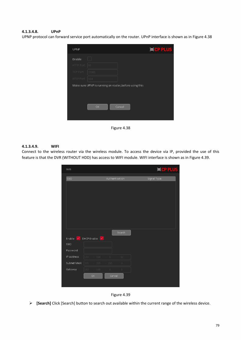
79
4.1.3.4.8. UPnP UPNP protocol can forward service port automatically on the router. UPnP interface is shown as in Figure 4.38
Figure 4.38
4.1.3.4.9. WIFI Connect to the wireless router via the wireless module. To access the device via IP, provided the use of this
feature is that the DVR (WITHOUT HDD) has access to WIFI module. WIFI interface is shown as in Figure 4.39.
Figure 4.39
➢ [Search] Click [Search] button to search out available within the current range of the wireless device.

80
➢ [Enable] To Enable or disable WIFI Service.
➢ [DHCP] To Enable or Disable DHCP.
➢ [SSID] Wireless LAN name; automatically match connected wireless devices.
➢ [Password] Wi-Fi router's password.
➢ [IP address] Set the device's IP address, default: 192.168.1.12.
➢ [Subnet Mask] Set the device subnet mask, default: 255.255.255.0
➢ [Default Gateway]: Set the device's default gateway, default: 192.168.1.1.
4.1.3.4.10. Alarm Push To get Push notification on mobile application, interface is shown as in Figure 4.40
Figure 4.40
➢ [Enable] To Enable or disable Mobile reported service.
4.1.3.4.11. HMS HMS is a heath monitoring system, interface as shown in Figure 4.41. To configure HMS or for more details please
contact to CPPLUS Support team.
Figure 4.41

81
4.1.4. Storage Main Stream Schedule
To Schedule Main Stream recording in connected HDD. User need to have proper rights to implement the
following operations. Please make sure the HDDs have been properly installed.
After the system booted up, it is in default 24-hour regular mode. User can set record type and time in schedule
interface as shown in Figure 4.42.
Figure 4.42
➢ [Channel] Please select the channel number first. User can select “all” if user want to set for the whole
channels.
➢ [Redundancy] System supports redundancy backup function. User can highlight Redundancy button to
activate this function. Please note, before enabling this function, please set at least one HDD as redundant.
(Main Menu →Storage → HDD Manager). Please note this function is null if there is only one HDD.
➢ [Rec Duration] Here we can define maximum length of recorded file in HDD. It could be 1 ~ 120 Min.
➢ [Pre-Rec] Here we can define the pre-record time before the event occurs into the file. It could be 0 ~ 30Sec.
➢ [Mode] Here we can select recording mode like Schedule and Manual or we can stop recording in HDD.
➢ [Week] There are eight options: ranges from Saturday to Sunday and all.
➢ [Record Type] Please check the box to select corresponding record type. There are two types:
Regular/Detect (Motion Detect).
➢ Period: Create time period according to record schedule and record type.

82
Sub Stream Schedule To schedule Extra Stream/Sub Stream recording in connected HDD. Interface as shown in Figure 4.43. For
configuration details please check chapter “4.1.4.1”.
Figure 4.43
Snapshot To Schedule Snapshot recording in Connected HDD. Interface as shown in Figure 4.44. User need to have proper
rights to implement the following operations. Please make sure the HDDs have been properly installed. After the
system booted up, it is in default 24-hour regular mode. User can set record type and time in schedule.
Figure 4.44

83
➢ [Channel] Please select the channel number first. User can select “all” if user want to set for the whole
channels.
➢ [Pre-Snap] Here we can define delay between Snapshot recording. We can set the value from 5 ~ 3600 sec.
➢ [Mode] Here we can select recording mode like Schedule or we can stop recording in HDD.
➢ [Week] There are eight options: ranges from Saturday to Sunday and all.
➢ Period: Create time period according to record schedule and record type.
Note – To record Snapshot in HDD, user need to allocate image partition from HDD manage page Main Menu →
Storage → HDD Manage → Partition.
HDD Manage Configure and manage the hard disk. The menu displays current hard disk information: hard disk number, input
port, type, status and overall capability. The operation includes: setup the Read/Write Disk, Read Only Disk,
Redundant Disk, Hard Disk Format, Recover Disk and Disk Partition. Choose the hard disk and click the right
function button to execute. See Figure 4.45
Figure 4.45
➢ [Read/Write] The equipment can read and write data on HDD.
➢ [Read Only Disk] The equipment can read data but cannot write data on HDD.
➢ [Redundant Disk] Double backup the video files in the Read/Write disk.
➢ [Format Storage] To format Selected HDD.
Note: If click on format storage then all data from HDD will be erased. Before format HDD please make sure
Device, time and time should be correct.
➢ [Recover] To recover lost data from HDD.
➢ [Partition] To create Partition in selected HDD. User need to create partition to record video and
snapshot separately.

84
➢ [Snapshot] To dedicate connected HDD only for snapshot recording.
4.1.5. System General
General interface is shown as in Figure 4.46.
Figure 4.46
➢ [Time Zone] To set time zone for DVR (WITHOUT HDD) according to device location. The default is GMT
+1:00.
➢ [System time] Set the system date and time manually.
➢ [Date Format] Provide Year/Month/Day, Month/Day/Year, Day/Month/Year three formats.
➢ [Daylight Saving Time]: Daylight Saving Time feature set start time and end of daylight saving time, as
shown in Figure 4.47 and Figure 4.48.
Figure 4.47

85
Figure 4.48
➢ [Date separator] Set the preview screen displays the date when the delimited format, provide a "-", ".",
"/" three formats.
➢ [Time Format] Select the time format of 12 or 24-hour two kinds, default is 24.
➢ [Language] Set the system language, Simplified Chinese, Traditional Chinese, English and other 20
languages.
➢ [HDD Full] Here is for user to select working mode when hard disk is full. There are two options: Stop
Recording or Overwrite. If current working HDD is overwritten or the current HDD is full while the next
HDD is no empty, then system stops recording, If the current HDD is full and then next HDD is not empty,
then system overwrites the previous files.
➢ [DVR NO.] Here user can set device number.
➢ [Video Standard] Select the video format supports both PAL and NTSC formats.
➢ [Auto Logout] Here is for user to set auto logout interval once login user remains inactive for a specified
time. Value ranges from 0 to 60 minutes.
➢ [Device Name] can be set to the name of the device.

86
PTZ Config The pan/tilt/zoom setup includes the following items. Please select channel first. See in Figure 4.49.
Figure 4.49
➢ [Channel] Select the channel on which PTZ connected.
➢ [Control Method] User can select control method from the dropdown list. There are three options:
Coaxial, RS485 and All. For CVI series product, please select Coaxial. The control signal is sent to the PTZ
via the coaxial cable. For the RS485 mode, the control signal is sent to the PTZ via the RS485 port.
➢ [Protocol] To select the protocols (e.g.: CP-SD, PelcoD).
➢ [Address] Input corresponding PTZ address.
➢ [Baud rate] Select baud rate.
➢ [Data bit] Select data bit.
➢ [Stop bit] Select stop bit.
➢ [Parity] There are five choices: none/odd/even/mark/space.

87
Auto Maintenance The user can set the time to auto reboot and auto delete file. Auto Maintenance interface is shown as in Figure
4.50
Figure 4.50
Default To Default Device settings, Default interface is shown as Figure 4.51
• General
• Encode
• Schedule
• Alarm Set
• Network
• Advance Settings
• Display
• Account
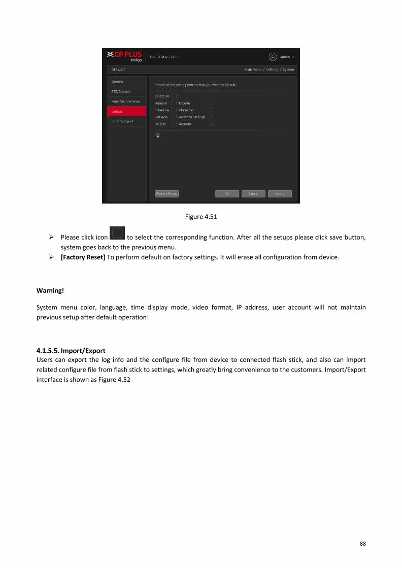
88
Figure 4.51
➢ Please click icon to select the corresponding function. After all the setups please click save button,
system goes back to the previous menu.
➢ [Factory Reset] To perform default on factory settings. It will erase all configuration from device.
Warning!
System menu color, language, time display mode, video format, IP address, user account will not maintain
previous setup after default operation!
Import/Export Users can export the log info and the configure file from device to connected flash stick, and also can import
related configure file from flash stick to settings, which greatly bring convenience to the customers. Import/Export
interface is shown as Figure 4.52

89
Figure 4.52
Note:
⚫ System cannot open config backup interface again if there is backup operation in the process.
⚫ System refreshes device when user go to the config backup every time and set current directory as the root
directory of the peripheral device.
⚫ If user go to the configuration backup interface first and then insert the peripheral device.

90
4.2. Information 4.2.1. Info
HDD info Display the hard disk information, including HDD info. HDD info interface is shown as in Figure 4.53
Figure 4.53
Tips: ○ means that the hard disk is normal. “-” means that there is no hard disk. If the user needs to change the
damaged hard disk, user must shut down the DVR (WITHOUT HDD) and take up all the damaged hard disks, then
install a new one.
* Behind serial number means the current working disk such as 1*. If the corresponding disk is damaged, the
information will show “?”
Device info Provide device interface info like audio in, alarm in/out to be conveniently used for user. Device info interface is
shown as in Figure 4.54

91
Figure 4.54
4.2.2. Online User To check the information of network user that connected with local device, also can tick the selected user to
break up connection and will not log in until device reboot or disconnect time over. Online user interface is shown
as in Figure 4.55
Figure 4.55

92
4.2.3. Log To search log information base on the set search mode. Log information include: system operation, configuration
operation, data management, alarm affair, recording operation, user management, and file management and so
on. Set the time section to look up and click the look up button. The log information will display as a list. (One
page is 128 items) Press Page up or Page down button to look up and press delete button to clear all the log
information. Log interface is shown as in
Figure 4.56
4.2.4. Version Display the basic information such as hardware information, software version, issue date, serial number and so
on. Version interface is shown as in Figure 4.57
Figure 4.57

93
4.2.5. BPS Display the code stream( Kb/S) and hard disk capability (MB/H) in real time. It displays as the wave sketch
map. BPS interface is shown as in Figure 4.58
Figure 4.58

94
4.3. Operation 4.3.1. Playback There are two methods for user to play the video files in the hard disk. Through shortcut menu or form [Main
Menu] → [Playback]. Playback interface is shown as in Figure 4.59
Note: The hard disk that saves the video files must be set as read-write or read-only state.
Figure 4.59
Please refer table for Playback page reference
1. Playback control 2. Recorded files 3. Synchronous 4. Video type
5. Time Split 6. File List 7. File Search 8. Channel Selection
9. Extra Stream 10. Record Calendar 11. Device Selection 12. Preview Window

95
For Playback control please refer below table
Button Function Button Function
/
Play/Pause
Play Backward
Stop
Slow Playback
Reverse Fast
Fast Playback
Previous Frame
Next Frame
Previous File
Next File
Repeat Playback
Full Screen
Start Video Clipping
End Video Clipping
Download Enable/Disable Audio
Note: Play under frame by frame, the playback status should be paused firstly. [Operation tips] show function of
the key that cursor placed.

96
Special functions:
Local zoom: When the system is in single-window full-screen playback mode, user can drag mouse in the screen
to select a section and then left click mouse to realize local zoom. User can right click mouse to exit.
4.3.2. Backup By setting the backup device video file to an external storage device. Backup interface is shown as in Figure 4.60
Note: Before backup files, user need to install the files stored to accommodate storage devices. Backup is
terminated; it has been copied to a storage device files can be played back independently.
Backup middle is terminated, has been copied to a storage device files can be played back independently.
Figure 4.60
➢ [Detection] Detecting storage devices connected to the device, which can be U disk, hard disk and other
equipment.
➢ [Backup] Click Backup, Backup dialog box pops up, user can select the backup video files based on type,
channel, time and other attributes.
Select backup device and then set channel, file start time and end time. Click add button, system begins search. All
matched files are listed below. System automatically calculates the capacity needed and remained. See Figure
4.61.

97
Figure 4.61
Systems only take backup of selected files. Click Start button, system begins copy. At the same time, the backup
button becomes stop button. User can view the remaining time and process bar at the left bottom. See Figure
4.62.
Figure 4.62
When the system completes backup, user can see a dialogue box prompting Backup Finished. See Figure 4.63

98
Figure 4.63
Note: When user back up, user can exit the page perform other functions. Burn: Click Burn, burn video will sync
selected channel.
➢ [Instant Rec] User can instantly record live stream in backup drives, insert Backup drives like flash drive or
external drive in DVR (WITHOUT HDD) when the device detected by system then click on instant Rec. In
new window here to select channel No. and click on start button. DVR (WITHOUT HDD) will start
recording in backup drive until user click on stop button. See Figure 4.64
Figure 4.64
➢ [Format] Click here to format detected Backup drive.
4.3.3. Display Configure the video output parameters including Time Display, Channel Title, Record Status, Transparency,
Resolution, Tour, etc. Display interface is shown as in Figure 4.65

99
Figure 4.65
➢ [Time Display] Means the selective state. Display the system data and time in the live window.
➢ [Channel Title] Means the selective state. Display the system channel number in the live window.
➢ [Record Status] Means the selective state. Display the recording status in live window.
➢ [Alarm Status] Means the selective state. Display the system alarm status in the live window.
➢ [Transparency] Choose the background image transparency. The range is 10~100.
➢ [Resolution] Set display resolution. It includes: 1024x768, 1280x720, 1280x1024, 1440x900, and
1920x1080.
➢ [Tour] Set the patrol display. Click the tour button in new window, click to enable display tour option.
Mean that the tour mode is enabled. User can choose the single-view, four-view, eight-view of single
mode tour or hybrid mode tour. Tour interface is shown as in Figure 4.66.
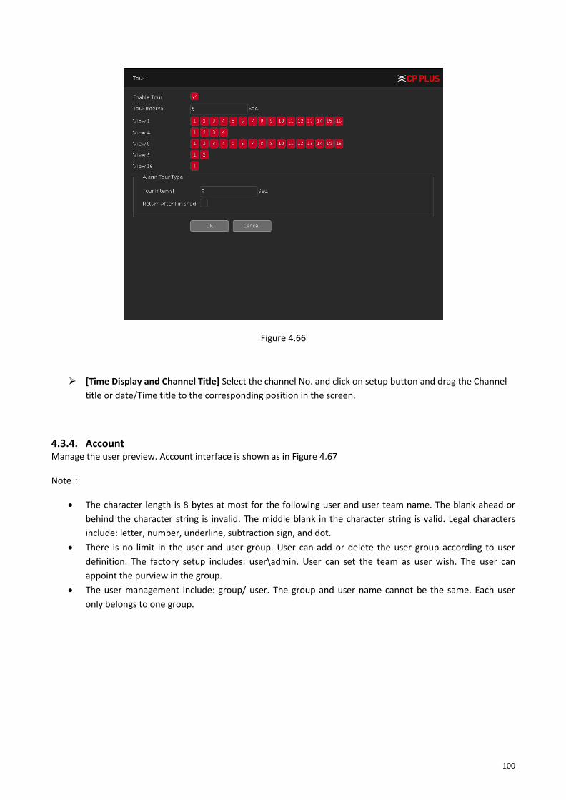
100
Figure 4.66
➢ [Time Display and Channel Title] Select the channel No. and click on setup button and drag the Channel
title or date/Time title to the corresponding position in the screen.
4.3.4. Account Manage the user preview. Account interface is shown as in Figure 4.67
Note:
• The character length is 8 bytes at most for the following user and user team name. The blank ahead or
behind the character string is invalid. The middle blank in the character string is valid. Legal characters
include: letter, number, underline, subtraction sign, and dot.
• There is no limit in the user and user group. User can add or delete the user group according to user
definition. The factory setup includes: user\admin. User can set the team as user wish. The user can
appoint the purview in the group.
• The user management include: group/ user. The group and user name cannot be the same. Each user
only belongs to one group.

101
Figure 4.67
➢ [Modify User] Modify the user name has been added, whether reuse, notes, group, class, and
permissions. See Figure 4.68
Figure 4.68
➢ [Modify Group] Group name has been added to modify the user group, notes and permissions. See
Figure 4.69
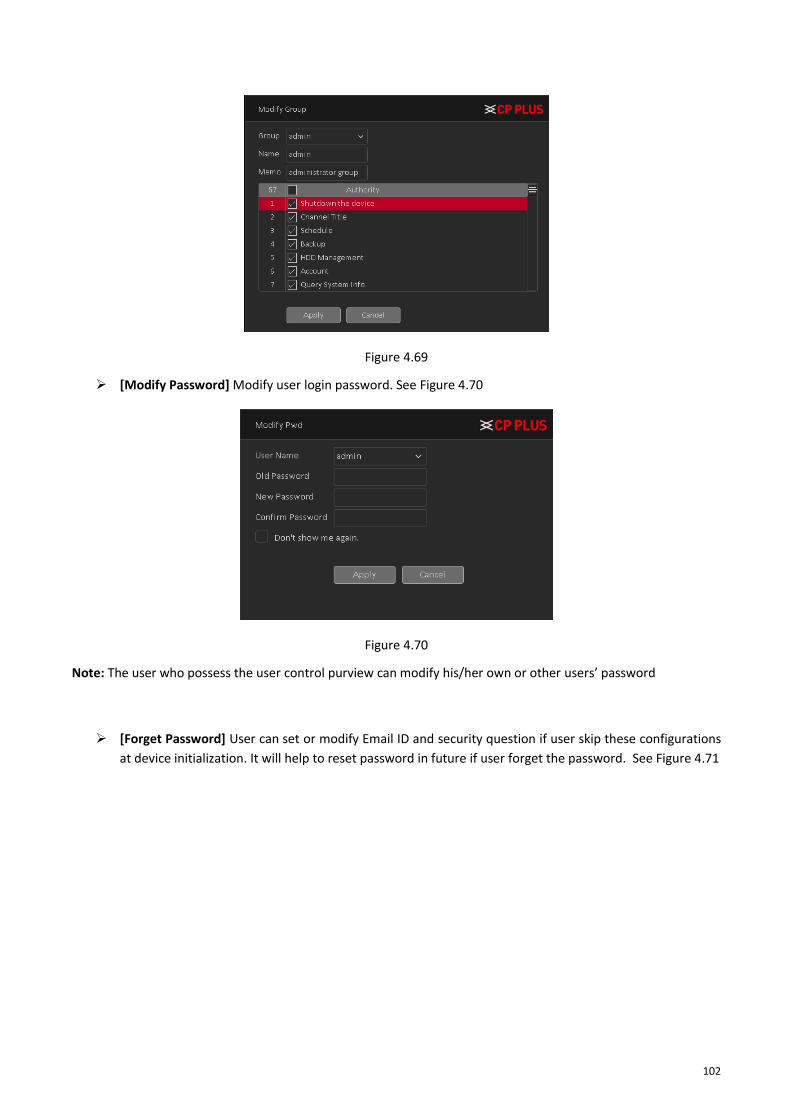
102
Figure 4.69
➢ [Modify Password] Modify user login password. See Figure 4.70
Figure 4.70
Note: The user who possess the user control purview can modify his/her own or other users’ password
➢ [Forget Password] User can set or modify Email ID and security question if user skip these configurations
at device initialization. It will help to reset password in future if user forget the password. See Figure 4.71

103
Figure 4.71
➢ [Modify Pattern] user can set or modify pattern to login device, if user skip this configuration at device
initialization. See Figure 4.72.
Figure 4.72

104
➢ [Add user] Set new user name, password, notes, owning group, permissions and other information, can
add up to 64 user names. See Figure 4.73
Figure 4.73
➢ [Add Group] Set the group name new user group, notes, permissions and other information. See Figure
4.74
Figure 4.74
➢ [Delete User] Delete the selected user, the user cannot delete the admin user.
➢ [Delete Group] Delete the selected user group, when the group contains a user group cannot be deleted.
See Figure 4.75
Figure 4.75

105
4.3.5. Upgrade To upgrade device firmware, Upgrade interface is shown as in Figure 4.76
Figure 4.76
➢ [Upgrade from USB] choose USB drive and firmware upgrade file and then click on Upgrade button to
start upgrade process.
➢ [Online Upgrade] When the Device is connected to Internet, user can use online upgrade function to
upgrade the device.
Before using this function, user need to check if there is any new version by auto check or manual check.
• Auto check: The Device checks if there is any new version available at intervals.
• Manual check: Perform real-time check if there is any new version available.
Ensure the correct power supply and network connection during upgrading; otherwise the upgrading might be
failed.

106
➢ [Camera Upgrade] Select the channel no. of which user want to upgrade firmware and after selecting
drive, firmware file then clicks on upgrade. This feature will only work with particular IPC device which
added through private protocol.
Note: Please make sure power should not be interrupt during firmware upgrade process; neither Device will be
malfunctioned (dead condition).

107
5. Web Operation Slightly difference may be found in the interface due to different models.
5.1. Network Connection Before web client operation, please check the following items:
⚫ Network connection should be proper.
⚫ DVR (WITHOUT HDD) and PC network setup is proper. Please refer to network setup (Main Menu → Setting
→ Network)
⚫ Use order ping ***.***.***.*** (* DVR IP address) to check connection is OK or not. Usually the return TTL
value should be less than 255.
⚫ Current series product supports various browsers such as Safari, fire fox browser, Internet Explorer. Device
supports multiple-channel monitor, PTZ control, DVR parameter setup on the Apple PC.
5.2. Login Open IE and input DVR address in the address bar. For example, if DVR IP is 192.168.1.240, then please input
http://192.168.1.240 in IE address bar.
System pops up warning information to ask user whether Install control or block. Please click Install button. See
Figure 5.1.
Figure 5.1
After installation, the interface is shown as below. See Figure 5.2. Please input user name and password. Default
factory name is admin and password are admin.
Note: For security reasons, please modify password after user first login.

108
Figure 5.2
System pops up the following dialogue box for user to change default administrator password. See Figure 5.3
Figure 5.3
For user own safety, please change the default password after user first login.

109
5.3. LAN Mode For the LAN mode, after user logged in, user can see the main window. See Figure 5.4
Figure 5.4
This main window can be divided into the following sections.
⚫ Section 1: There are five function buttons: Preview, Playback, Alarm, Setup, Info, and Logout.
⚫ Section 2: There are channel numbers to open
⚫ Section 3: There are two function buttons: Open All to access all cameras and Close all to close all cameras.
⚫ Section 4: User can click this button to enable audio talk. After user enable the bidirectional talk, the Start
talk button becomes Stop Talk button and it becomes Red.
Note - if audio input port from the device to the client-end is using the first channel audio input port. During the
bidirectional talk process, system will not encode the audio data from the 1-channel.
⚫ Section 5: User can click this to enable manual record for all channels.
⚫ Section 6: PTZ operation panel.
⚫ Section 7: Image setup, see in Figure 5.5.

110
Figure 5.5
⚫ Section 8: From left to right, it is to set Full Screen and Grid View icon.
⚫ Section 9: Digital Zoom, Local Recording, Local snapshot and Enable/Disable sound.
5.4. Real-Time Monitor In section 2, left click the channel name user want to view, user can see the corresponding video in current
window.
In Real-Time Monitor window, user will get some icons which are marked as section 9 –
➢ Digital Zoom – For digital zoom please click on icon and drag mouse while pressing left click on selected
area of real-time video. To disable digital zoom please click on same icon.
➢ Local Record – Please click on To start and stop local recording of real-time video.
➢ Local Snapshot – Please click on to capture local snapshot of real-time video.
➢ Audio – Please click on to enable/disable audio.
5.5. PTZ Before PTZ operation, please make sure user have properly set PTZ protocol. There are eight direction keys. In the
middle of the eight direction keys, there is a 3D intelligent positioning key.
Please refer to the following sheet for PTZ setup information.
Parameter Function
Preset ⚫ Select Preset from the dropdown list.
⚫ Turn the camera to the corresponding position and Input the preset
value. Click Add button to add a preset.

111
Parameter Function
Tour ⚫ Select Tour from the dropdown list.
⚫ Input preset value in the column. Click Add preset button, user have
added one preset in the tour.
⚫ Repeat the above procedures user can add more presets in one tour.
⚫ Or user can click delete preset button to remove one preset from the
tour.
5.6. WAN Login In WAN mode, after user logged in, the interface is shown as below. See Figure 5.6
Figure 5.6
Please refer to the following contents for LAN and WAN login difference.
• In the WAN mode, system opens the sub stream of all channels to monitor by default.
• User can select different channels and different monitor modes at the bottom of the interface.
Important
The window display mode and the channel number are by default. For example, for the 16-channel, the max
window split mode is 16.

112
• Multiple-channel monitor, system adopts extra stream to monitor by default. Double click one channel,
system switches to single channel and system uses main stream to monitor. User can view there are two
icons at the left top corner of the channel number for user reference. M stands for main stream. S stands
for sub stream (extra stream).
• If user login via the WAN mode, system does not support alarm activation to open the video function in
the Alarm setup interface.
Important
⚫ For multiple-channel monitor mode, system adopts extra stream to monitor by default. User cannot modify
manually. All channels are trying to synchronize. Please note the synchronization effect still depends on
network environments.
For bandwidth consideration, system cannot support monitor and playback at the same time. System auto closes
monitor or playback interface when user is searching setup in the configuration interface. It is to enhance search
speed.
5.7. Playback Click Playback button, user can see an interface is shown as in Figure 5.7.
Figure 5.7
Please refer to the following sheet for Playback Page information.
Section Parameter Function
1 Playback Window
Display the searched recorded video or picture. It supports playing in single-channel, 4-channel, 9-channel, and 16-channel simultaneously. User can customize grid view of playback window through Section 3.

113
Section Parameter Function
2 Calendar
Click the date that user want to search, the time bar displays the
corresponding record.
The dates with record or snapshot have a small solid circle under
the date
3 Grid and Full
Screen
User can select grid view for Playback window as per the choice.
Here user can select single window, 4-window grid, 9-window
grid and so on. User can also select full screen window.
Note – Grid Window selection option is depending on Device
Specification.
4 Channel Selection To Select the channel for which user want to check playback.
5 Extra Stream Enable it to check extra stream recording playback.
6 Local Play
To Play local recorded files. For Details about Local Play, please
see Chapter “Local Play”
7 File List To Select Channel, user want to get playback. For Details about
File List, please see Chapter “File List”
8
Playback Control
Button
To Play, Pause, Stop, Fast forwarding and Control Playback Audio
level. For Details about playback control, please see Chapter
“Playback Control Button”
9 Time Bar
Display the type and time period of the current recorded video –
◼ In the 4-channel layout, there are four time bars are displayed; in the other view layouts, only one time bar is displayed.
◼ Click on the colored area to start playback from a certain time.
◼ In the situation when user are configuring the settings, rotate the wheel button on the time bar, the time bar is zooming in from 0. In the situation when playback is ongoing, rotate the wheel button on the time bar, the time bar is zooming from the time point where the playback is located.
◼ Time bar colors: Green indicates Regular type, Red indicates external alarm and Yellow indicates motion detection

114
Section Parameter Function
10 Video Splice
Splice a section of recorded video and save it. For details about
splicing a recorded video. For Details about Video splice, please
see Chapter “Clipping recorded Video”
11 Record type Select the check box to define the recording type to search for.
12 Time Bar Unit
User can select 24hr, 2hr, 1hr, or 30min as user drag time bar. The time bar display changes with the setting.
5.7.1. Local Play In Section 6, user can play local recorded files through this option, please check on Local play button as interface
shown as Figure 5.8.
Figure 5.8
✓ Click on , to browse local recorded file. Interface as shown in Figure 5.9.

115
Figure 5.9
5.7.2. File List In Section 7, user can get the all recorded files for select channel of selected date in playback calendar. Interface
shown as in
Figure 5.10
User can search record files as per time, also can download recorded file in local by selecting files and click on
download button.
5.7.3. Playback Control Button In Section 8, here user can perform playback controls like Play, pause, Stop, Playback fast forward speed and
audio control.
Please refer to the following sheet for Playback control information.

116
Icon Function Icon Function
Play
Next Frame
Pause
Fast and Slow
Forward
Stop
Audio Control
5.7.4. Clipping recorded Video In Section 10, user can clip recorded video and save it in Local drives. Interface in shown as in Figure 5.11
Figure 5.11
✓ Select a recorded video that user wants to play.
o Click , to start playing for beginning.
o Double-click anywhere in the time bar colored area to start playback.
✓ Click on the time bar to select the start time, and then click to start clipping.
✓ Again, click on time bar to select end time and then click again .
✓ Now click on .
✓ Download List- Select the file(s) user want to download and then click download button, user can see an
interface shown as in Figure 5.12. Click on browse button to Select file Destination and Select Record type
like H264 or AVI and click on OK button to start Download.
Figure 5.12

117
5.8. Alarm Click alarm function, user can see an interface is shown as Figure 5.13. Here user can set device alarm type and
alarm sound setup (Please make sure user have enabled audio function of corresponding alarm events).
Figure 5.13
Please refer to the following sheet for detailed information.
Type Parameter Function
Alarm Type
Motion Detection System alarms when motion detection alarm occurs.
Tampering System alarms when camera is viciously masking.
Disk Error System alarms when disk error occurs.
Video Loss System alarms when video loss occurs.
Disk Full System alarms when disk is full.
IVS System Alarms when IVS Detect
Operation
Prompt
Check the box here, system can automatically pop-up an
alarm icon on the Alarm button in the main interface
when there is an alarm.
Alarm Sound Play alarm sound
System sends out alarm sound when an alarm occurs.
User can specify as user wish.
Sound path Here user can specify alarm sound file.

118
5.9. Setup 5.9.1. Camera
Add IP devices Add IP device interface is shown as in Figure 5.14
Figure 5.14
✓ [Search] Select IP address or MAC Address and input particular IPC details and click on Search button.
✓ [Device Search] Click it to search IP address. It includes device Protocol, Device Info (MAC Address), IP
address and Port. Use mouse to click , user can refresh display order. Click IP
address, system displays IP address in ascending order. Click IP address again, user can see icon, system
displays IP address in Descending order. User can click other items to view information conveniently.
✓ [Add] Click it to connect to the selected device and add it to the Added device list.
✓ [Manual Add] Click it to add the IPC manually at custom level. See Figure 5.15

119
Figure 5.15
➢ [Channel Number] Select channel no.
➢ [Device Type] 3 types: IPC, DVR (WITHOUT HDD), And NVR. User can choose as what user like, default
is IPC.
➢ [Protocol] There are two protocols Private and ONVIF, the default is Private.
➢ [IP Channel] User can input remote channel title from the device that user want to connect remotely.
➢ [IP Address] To enter Device IP Address. It supports only IPv4.
➢ [Port] TCP port of remote device, by default is 25001.
➢ [User name] To input user name of remote device, by default is admin
➢ [Password] To input remote device password for selected user, by default is admin.
➢ [Connection Mode] Can be singe connect or multi-ink, multi-link modes can connect to several
devices, device will be tour displayed one by one, tour interval can be set, no less then 10s.
➢ [Time Sync] To disable or select time synchronization mode with device and UTC.
➢ [Decode Order] To select mode of network video stream transmission. It includes: Real Time, Middle
and Fluency.
➢ [Synchronization Resolution] To enable resolution modification of network camera through DVR
(WITHOUT HDD) end.
✓ [Delete] Click it to delete existing device, if the user wants to change device. Select the existing device and
click on Delete.
✓ [Save] To Save Add IP device configuration.
✓ [Refresh] To refresh added IPC connection status.
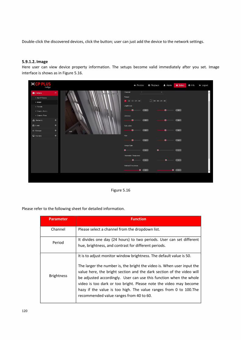
120
Double-click the discovered devices, click the button; user can just add the device to the network settings.
Image Here user can view device property information. The setups become valid immediately after you set. Image
interface is shows as in Figure 5.16.
Figure 5.16
Please refer to the following sheet for detailed information.
Parameter Function
Channel Please select a channel from the dropdown list.
Period It divides one day (24 hours) to two periods. User can set different
hue, brightness, and contrast for different periods.
Brightness
It is to adjust monitor window brightness. The default value is 50.
The larger the number is, the bright the video is. When user input the
value here, the bright section and the dark section of the video will
be adjusted accordingly. User can use this function when the whole
video is too dark or too bright. Please note the video may become
hazy if the value is too high. The value ranges from 0 to 100.The
recommended value ranges from 40 to 60.

121
Contrast
It is to adjust monitor window contrast. The value ranges from 0 to
100. The default value is 50.
The larger the number is, the higher the contrast is. User can use this
function when the whole video bright is OK, but the contrast is not
proper. Please note the video may become hazy if the value is too
low. If this value is too high, the dark section may lack brightness
while the bright section may over exposure. The recommended value
ranges from 40 to 60.
Saturation
It is to adjust monitor window saturation. The value ranges from 0 to
100. The default value is 50.
The larger the number is, the strong the color is. This value has no
effect on the general brightness of the whole video. The video color
may become too strong if the value is too high. For the grey part of
the video, the distortion may occur if the white balance is not
accurate. Please note the video may not be attractive if the value is
too low. The recommended value ranges from 40 to 60.
Hue
It is to adjust monitor video brightness and darkness level. The
default value is 50.
The bigger the value is, the large the contrast between the bright and
dark section is and vice versa.

122
Encode 5.9.1.3.1. Encode The encode interface is shown as below. See Figure 5.17.
Figure 5.17
Please refer to the following sheet for detailed information.
Parameter Function
Channel Please select a channel from the dropdown list.
Video enable Check the box here to enable extra stream video. This item is
enabled by default.
Compression Compression: System supports H.264 or H.265.
H.264: It is the High-Profile compression algorithm. It has the
high encode compression rate. It can achieve high quality
encode at low bit stream. Usually we recommend this type.
H.265: High Efficiency Video Coding (HEVC), also known as H.265 and MPEG-H Part 2, is a video compression standard, designed as a successor to the widely used AVC (H.264 or MPEG-4 Part 10).
Resolution For analog channel, system supports various resolutions, user can
select from the dropdown list. Please note the option may vary due

123
to different series. For digital channel, the resolution here refers to
the capability of the network camera.
Frame Rate PAL:1~25f/s;NTSC:1~30f/s.
Bit Rate Type System supports two types: CBR and VBR. In VBR mode, user can set
video quality.
Image Quality There are six levels ranging from Lowest to Highest. The sixth level
has the highest image quality
Bit Rate Recommended bit rate value according to the resolution and frame
rate user have set.
I Frame Here user can set the P frame amount between two I frame. The
value ranges from 1 to 150. Default value is 50.
Recommended value is frame rate *2.
Smart Codec Enable the smart codec function. This function can reduce the video bit stream for non-important recorded video to maximize the storage space.
Audio/Video
Enable
User can enable or disable the video/audio.
5.9.1.3.2. Path
The storage path interface is shown as in Figure 5.18. Here user can set snap image saved path ( in the
preview interface) and the record storage path ( in the preview interface). Please click the Save button to
save current setup.

124
Figure 5.18
Channel Name Here user can set channel name. See Figure 5.19. Please note this function is for analog channel only. The digital
channel name here is read-only.
Figure 5.19
Channel Type It is to set channel type. Each channel supports analog camera HD Analog / Network camera connection. Please
note DVR (WITHOUT HDD) needs to restart to activate new setup. The network camera connection shall begin
with the last channel. For the 16-channel (or higher) series product, please go to the next page to set. See Figure
5.20.

125
Figure 5.20
5.9.2. Network TCP/IP
5.9.2.1.1. TCP/IP TCP/IP interface is shown as in Figure 5.21.
Figure 5.21
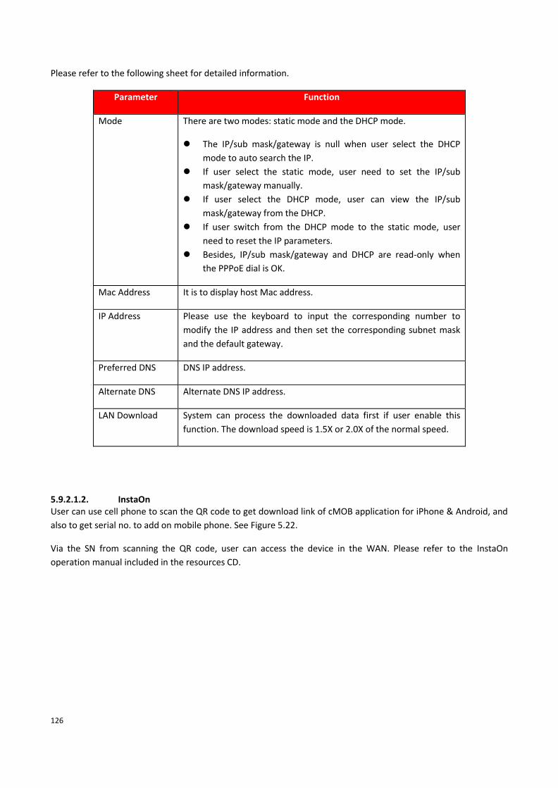
126
Please refer to the following sheet for detailed information.
Parameter Function
Mode There are two modes: static mode and the DHCP mode.
⚫ The IP/sub mask/gateway is null when user select the DHCP
mode to auto search the IP.
⚫ If user select the static mode, user need to set the IP/sub
mask/gateway manually.
⚫ If user select the DHCP mode, user can view the IP/sub
mask/gateway from the DHCP.
⚫ If user switch from the DHCP mode to the static mode, user
need to reset the IP parameters.
⚫ Besides, IP/sub mask/gateway and DHCP are read-only when
the PPPoE dial is OK.
Mac Address It is to display host Mac address.
IP Address Please use the keyboard to input the corresponding number to
modify the IP address and then set the corresponding subnet mask
and the default gateway.
Preferred DNS DNS IP address.
Alternate DNS Alternate DNS IP address.
LAN Download System can process the downloaded data first if user enable this
function. The download speed is 1.5X or 2.0X of the normal speed.
5.9.2.1.2. InstaOn User can use cell phone to scan the QR code to get download link of cMOB application for iPhone & Android, and
also to get serial no. to add on mobile phone. See Figure 5.22.
Via the SN from scanning the QR code, user can access the device in the WAN. Please refer to the InstaOn
operation manual included in the resources CD.

127
Figure 5.22
Connection The connection interface is shown as in Figure 5.23.
Figure 5.23
Please refer to the following sheet for detailed information.
Parameter Function
TCP port The default value is 37777. User can input the actual port number if necessary.
HTTP port The default value is 80. User can input the actual port number if necessary.
RTSP port The default value is 554.

128
Wi-Fi Please note this function is for the device of WIFI module. The WIFI interface is shown as in Figure 5.24
Figure 5.24
Please check the box to enable WIFI function and then click the Search SSID button. Now user can view all the
wireless network information in the following list. Double click a name to connect to it. Click Refresh button, user
can view latest connection status.
3G The CDMA/GPRS interface is shown as in Figure 5.25
Figure 5.25

129
Please refer to the following sheet for detailed information.
Parameter Function
Network type Here user can select 3G network type to distinguish the 3G module
from different ISP. The types include WCDMA,CDMA1x and etc.
ISP To Select ISP predefine Setting for APN, Dial No. User and Password.
It includes TATA, AIRCEL, AIRTEL, MTS, BSNL, RELIANCE CDMA,
RELIANCE GSM, TATA DOCOMO, MTNL and customized.
Wireless AP To input 3G access point.
Dial No. Input 3G dialup number.
User Name Input Dial 3G username
Password Input dial user's password
WLAN Status The IP address, Subnet mask and gateway of the dial-up number to
get.
PPPoE The PPPoE interface is shown as in Figure 5.26.
Input the PPPoE user name and password user get from the IPS (internet service provider) and enable PPPoE
function. Please save current setup and then reboot the device to get the setup activated.
Device connects to the internet via PPPoE after reboot. User can get the IP address in the WAN from the IP
address column.
Please note, user need to use previous IP address in the LAN to login the device. Please go to the IP address item
to via the device current device information. User can access the client-end via this new address.
Figure 5.26

130
DDNS DDNS setup interface is shown as in Figure 5.27.
Figure 5.27
Please note DDNS type includes: CPPLUS DDNS, Dyndns and NO-IP DDNS. All the DDNS can be valid at the same
time, user can select as per requirement.
CPPLUS DDNS and Client-end Introduction
➢ Background Introduction
Device IP is not fixed if user use ADSL to login the network. The DDNS function allows user to access the DVR
(WITHOUT HDD) via the registered domain name. Besides the general DDNS, the CPPLUS DDNS works with the
device from the manufacturer so that it can add the extension function.
➢ Function Introduction
The CPPLUS DDNS has the same function as other DDNS client end. It realizes the bonding of the domain name
and the IP address. Right now, current DDNS server is for our own devices only. It automatically refreshes the
bonding relationship of the domain and the IP regularly.
➢ Operation
• Select CPPLUS DDNS and click on check box to enable DDNS service.
• User can input self-defined domain name in Domain name field.
• Click on Apply button, device will check the availability of defined domain name on DDNS server. If same
Domain name already registered on server then it will prompt message neither it will register domain
name on server.
• After successfully created Domain Name, click on OK button to save settings.

131
Important - Do not register frequently. The interval between two registrations shall be more than 60 seconds. Too
many registration requests may result in server attack.
IP Filter IP filter interface is shown as in Figure 5.28. User can add IP in the following list. System supports valid address of
IPv4 only. After user enabled Whitelist function, only the IP listed below can access current DVR (WITHOUT HDD).
If user enable Blacklist function, the following listed IP addresses cannot access current DVR (WITHOUT HDD).
Figure 5.28
• [Enable] Highlight the box here, user can check the trusted site function and blocked sites function.
• [Type] User can select Trusted Sites or Blocked Sites from the interface. User can view the IP address on the following column.
• [Add] Input a valid IP address (IPv4 only) and click on add button to add selected IP address for Blacklist or Whitelist.
• [Edit] To edit mentioned IP details.
• [Delete] Click it to remove specified item.
Note:
• If user enabled trusted sites, only the IP in the trusted sites list can access the device.
• If user enabled blocked sites, the IP in the blocked sites cannot access the device.
• System supports add MAC address.
Email The email interface is shown as in Figure 5.29.

132
Figure 5.29
Please refer to the following sheet for detailed information.
Parameter Function
Enable Please check the box here to enable email function.
SMTP Server Input server address and then enable this function.
Port Default value is 25. User can modify it if necessary.
Encrypt Type To select encryption mode, like SSL, TLS or None.
User Name The user name of the sender email account.
Password The password of sender email account.
Sender Sender email address.
Subject Input email subject here.
Receiver Input receiver email address here. Max three addresses.

133
FTP The FTP interface is shown as in Figure 5.30. It is to set FTP IP, port and etc. for remote storage.
Figure 5.30
Please refer to the following sheet for detailed information.
Parameter Function
Enable Please check the box here to enable email function.
Server IP To set IP address of the FTP server.
Port To set FTP server service port number, the default port 21.
User Name Input the user name of FTP Server authentication.
Password Input password of FTP server User authentication.
Anonymous If choose to be anonymous, then user do not need to set the user
name and password.
Remote Directory To set directory name to upload files.
File Length Each package upload files maximum length, default is 1024MB.
UPnP It allows user to establish the mapping relationship between the LAN and the public network. Here user can also
add, modify or remove UPnP item. See Figure 5.31.
In the Windows OS, From Start → Control Panel → Add or remove programs. Click the “Add/Remove Windows
Components” and then select the “Network Services” from the Windows Components Wizard.

134
• Enable UPnP from the Web. If UPnP is enabled in the Windows OS, the DVR (WITHOUT HDD) can auto detect
it via the “My Network Places”
Figure 5.31
Alarm Centre The alarm Centre interface is shown as below. See Figure 5.32. This interface is reserved for user to develop.
System can upload alarm signal to the alarm server when local alarm occurs.
Before user use alarm server, please set server IP, port and etc. When an alarm occurs, system can send out data
as the protocol defined, so the client-end can get the data.
Figure 5.32

135
Alarm Push To get Push notification on mobile application, interface is shown as in Figure 5.33.
Figure 5.33
➢ [Enable] To Enable or disable Mobile reported service.
HMS HMS is a heath monitoring system, interface as shown in Figure 5.34. To configure HMS or for more details please
contact to CPPLUS Support team.
Figure 5.34

136
5.9.3. Event Detect
5.9.3.1.1. Motion Detect The motion detect interface is shown as in Figure 5.35.
Figure 5.35
Figure 5.36
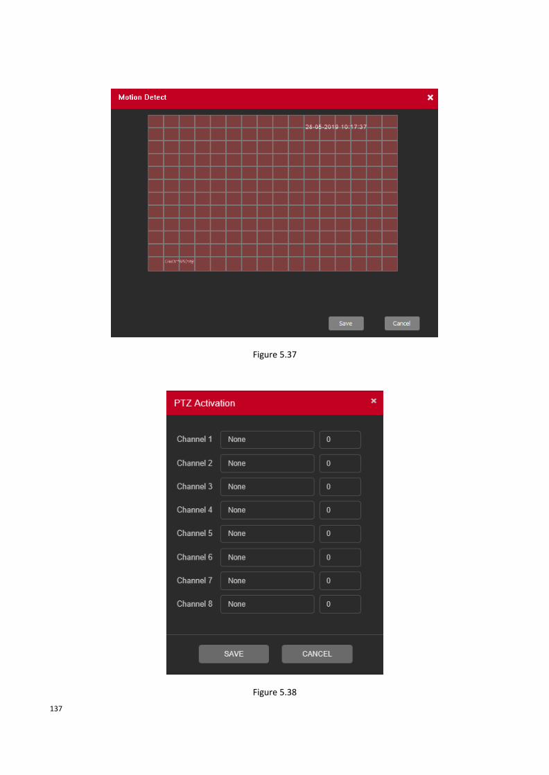
137
Figure 5.37
Figure 5.38

138
Please refer to the following sheet for detailed information.
Parameter Function
Enable User need to check the box to enable motion detection function.
Please select a channel from the dropdown list.
Period Motion detection function becomes activated in the specified periods.
See Figure 5.36.
There are six periods in one day. Please draw a circle to enable
corresponding period.
Click OK button, system goes back to motion detection interface; please
click save button to exit.
Interval System only memorizes one event during the anti-dither period. The
value ranges from 5s to 600s.
Region Click setup, enter the settings area is divided into 16X12 blocks, red
area for motion detection fortified area. The white area is undefended,
Settings area. Hold down the left mouse button, draw settings area. See
Figure 5.37 (By default the entire area selected for monitoring area).
Sensitivity There are six levels. The sixth level has the highest sensitivity.
Record channel System auto activates motion detection channel(s) to record once an
alarm occurs. Please note user need to set motion detects record
period and go to Storage → Schedule to set current channel as schedule
record.
Delay System can delay the record for specified time after alarm ended. The
value ranges from 10s to 300s.
PTZ Activation Here user can set PTZ movement when alarm occurs. Such as go to
preset X. See Figure 5.38.
Tour User need to check the box here to enable this function. System begins
1-wiindow or multiple-window tour display among the channel(s) user
set to record when an alarm occurs.
Show message System can pop up a message to alarm user in the local host screen if
user enabled this function.
Send Email If user enabled this function, System can send out an email to alert user
when an alarm occurs.

139
Parameter Function
Alarm upload System can upload the alarm signal to the server (Including alarm
server.
Buzzer Check the box here to enable this function. The buzzer beeps when an
alarm occurs.
FTP Expressed alarm occurs if the selected channel or video capture channel,
the video file up to FTP server.
Log Check the box here, system can record motion detect event log.
5.9.3.1.2. Video Loss The video loss interface is shown as in Figure 5.39.
After analysis video, system can generate a video loss alarm when the detected moving signal reached the
sensitivity user set here.
Figure 5.39

140
Figure 5.40
Figure 5.41

141
Please refer to the following sheet for detailed information.
Parameter Function
Enable User need to check the box to enable/disable Video Loss function. By
default, Video loss function enable for all channel. Please select a
channel from the dropdown list.
Period Video Loss function becomes activated in the specified periods. See
Figure 5.40.
There are six periods in one day. Please draw a circle to enable
corresponding period.
Click OK button, system goes back to Video Loss interface; please click
save button to exit.
Interval System only memorizes one event during the anti-dither period. The
value ranges from 5s to 600s.
Sensitivity There are six levels. The sixth level has the highest sensitivity.
Record channel System auto activates selected channels to record once an alarm occurs
Delay System can delay the record for specified time after alarm ended. The
value ranges from 10s to 300s.
PTZ Activation Here user can set PTZ movement when alarm occurs. Such as go to
preset X. See Figure 5.41.
Tour User need to check the box here to enable this function. System begins
1-wiindow or multiple-window tour display among the channel(s) user
set to record when an alarm occurs.
Show message System can pop up a message to alarm user in the local host screen if
user enabled this function.
Send Email If user enabled this function, System can send out an email to alert user
when an alarm occurs.
Alarm upload System can upload the alarm signal to the server (Including alarm
server.
Buzzer Check the box here to enable this function. The buzzer beeps when an
alarm occurs.
FTP Expressed alarm occurs if the selected channel or video capture channel,
the video file up to an FTP server.
Log Check the box here, system can record Video Loss event log.

142
5.9.3.1.3. Tampering The tampering interface is shown as in Figure 5.42.
After analysis video, system can generate a tampering alarm when the tampering signal reached the sensitivity
user set here.
Figure 5.42
Figure 5.43

143
Figure 5.44
Please refer to the following sheet for detailed information.
Parameter Function
Enable User need to check the box to enable/disable tampering function.
Please select a channel from the dropdown list.
Period Tampering function becomes activated in the specified periods. See
Figure 5.43.
There are six periods in one day. Please draw a circle to enable
corresponding period.
Click OK button, system goes back to Tampering interface; please click
save button to exit.
Interval System only memorizes one event during the anti-dither period. The
value ranges from 5s to 600s.
Sensitivity There are six levels. The sixth level has the highest sensitivity.
Record channel System auto activates selected channels to record once an alarm occurs
Delay System can delay the record for specified time after alarm ended. The
value ranges from 10s to 300s.

144
Parameter Function
PTZ Activation Here user can set PTZ movement when alarm occurs. Such as go to
preset X. See Figure 5.44.
Tour User need to check the box here to enable this function. System begins
1-wiindow or multiple-window tour display among the channel(s) user
set to record when an alarm occurs.
Show message System can pop up a message to alarm user in the local host screen if
user enabled this function.
Send Email If user enabled this function, System can send out an email to alert user
when an alarm occurs.
Alarm upload System can upload the alarm signal to the server (Including alarm
server.
Buzzer Check the box here to enable this function. The buzzer beeps when an
alarm occurs.
FTP Expressed alarm occurs if the selected channel or video capture channel,
the video file up to an FTP server.
Log Check the box here, system can record tampering event log.
5.9.3.1.4. IVS
IVS function processes and analyzes the images to extract the key information to match with the preset rules. When the detected behaviors match with the rules, the system activates alarms. IVS interface as shown in Figure 5.45.
Figure 5.45

145
✓ Enable IVS and Select the channel for which user want to create IVS rule.
✓ [Show Traces] It will trace and mark the object with green color lines in real-time video, while object
passing through IVS rule.
✓ [Show rules] It will display IVS rule parameters in real-time video.
✓ [Algorithm] To select IVS rule, there are three in drop-down menu
✓ [Alarm Linkage] Interface as shown in Figure 5.46. When system detect any alarm by IVS rule, then user
can perform various activity through like Display tour, record Snapshot, Activate PTZ, Show message and
So on.
Figure 5.46
o [Period] User can also set the alarm time from Monday to Sunday every day 4 time periods,
other time will not trigger IVS alarm information. See Figure 5.47.

146
Figure 5.47
o [Interval] between two alarms generate alarm information shortest time interval can be set
between 0 and 600Sec.
o [Record channel] When an alarm is triggered, the camera starts recording, user need to open IVS
recording.
o [Tour] Here user can enable tour function when alarm occurs. System one-window tour.
o [PTZ Activation] Here user can set PTZ movement when an alarm occurs. Such as go to preset,
tour &pattern when there is an alarm. Click “Setup” button, user can see an interface is shown as
in Figure 5.48.
Note: PTZ Activation, user need [shortcut menu] → [PTZ Control], set the preset point, tour between points,
intervals and other parameters

147
Figure 5.48
o [Post Rec] After the alarm ends, the length of time to continue the local recording can be set
between 10 and 300S.
o [Show Message] on the local host screen, pop-up dialog box prompts warning information.
o [Send Email] When an alarm is triggered, sends an alarm message to the specified mailbox,
through SMTP settings.
o [Buzzer] When an alarm occurs, the device sends a "Beep" sound long ring.
o [Log] Check the box here, system can record motion detect log.
o [FTP Upload] Expressed alarm occurs if the selected channel or video capture channel, the video
file up to an FTP server.
Note: Upload FTP, need to be set accordingly in the [Network Services].
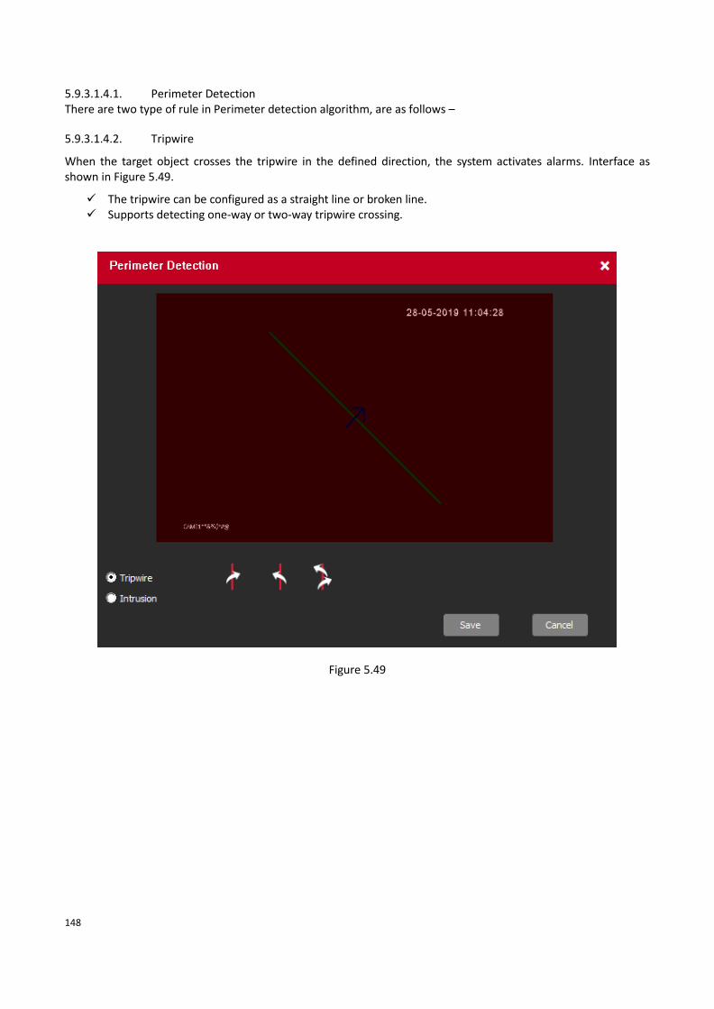
148
5.9.3.1.4.1. Perimeter Detection There are two type of rule in Perimeter detection algorithm, are as follows –
5.9.3.1.4.2. Tripwire
When the target object crosses the tripwire in the defined direction, the system activates alarms. Interface as shown in Figure 5.49.
✓ The tripwire can be configured as a straight line or broken line. ✓ Supports detecting one-way or two-way tripwire crossing.
Figure 5.49

149
5.9.3.1.4.3. Intrusion
When the target enters and leaves the area, or the target appears in the defined area, the system activates alarms. Interface as shown in Figure 5.50.
✓ User can define the shape and size of intrusion areas. ✓ Supports detecting the behaviors that enter and leave the intrusion areas.
Figure 5.50

150
5.9.3.1.4.4. Missing/Abandoned Object There are two type of rule in Missing/Abandoned algorithm, are as follows –
5.9.3.1.4.5. Abandoned Object When the object is placed in the defined detection area for more than the set time, the system activates alarms.
Interface as shown in Figure 5.51.
✓ User can define the shape and size of intrusion areas.
Figure 5.51

151
5.9.3.1.4.6. Missing Object When the target is taken away from the defined area exceeds the set time, the system activates alarms. Interface
as shown in Figure 5.52.
✓ User can define the shape and size of intrusion areas.
Figure 5.52
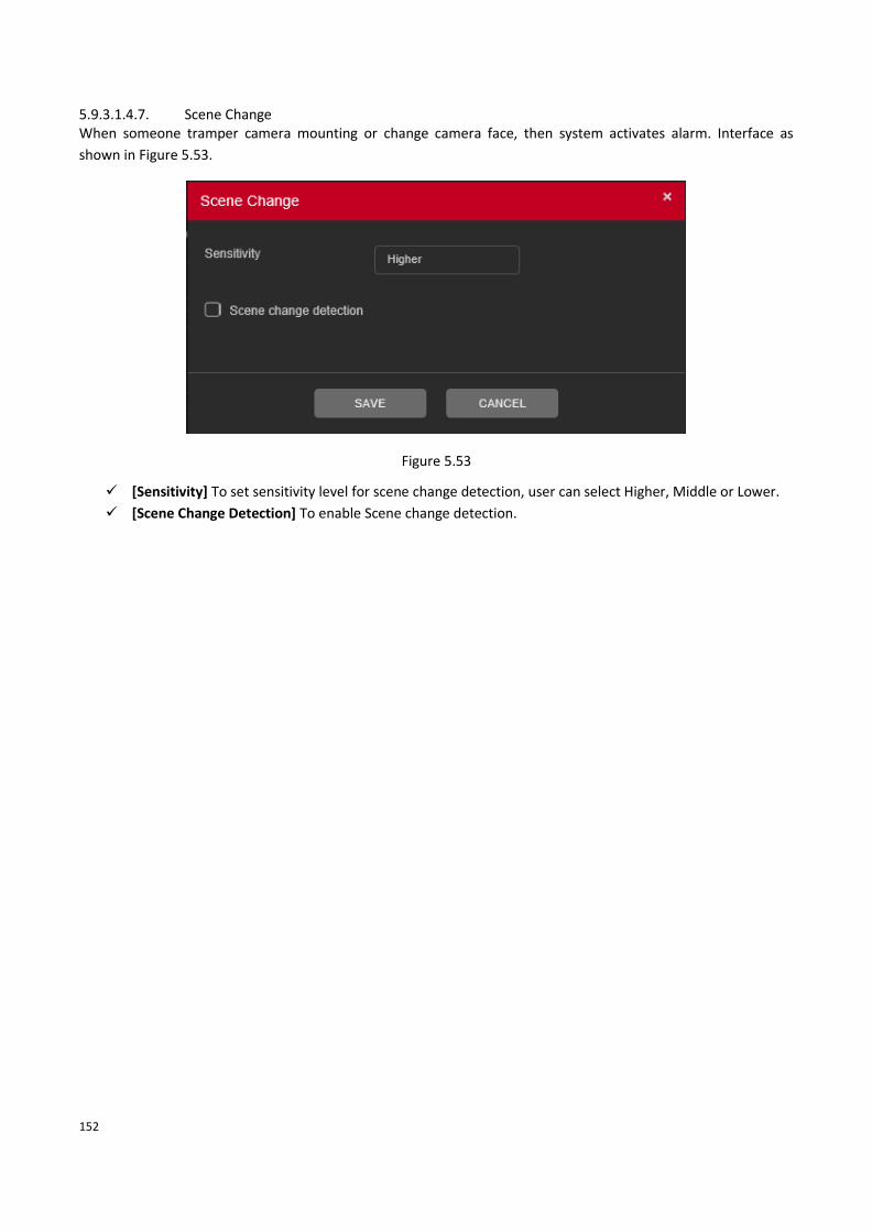
152
5.9.3.1.4.7. Scene Change When someone tramper camera mounting or change camera face, then system activates alarm. Interface as
shown in Figure 5.53.
Figure 5.53
✓ [Sensitivity] To set sensitivity level for scene change detection, user can select Higher, Middle or Lower.
✓ [Scene Change Detection] To enable Scene change detection.

153
Abnormality It includes two types: HDD and Network Error.
• HDD include: No disk, disk error, disk no space.
• Network includes: Net Disconnection, IP conflict, and MAC conflict.
5.9.3.2.1. HDD Error The HDD Error interface is shown as in Figure 5.54.
Figure 5.54
Please refer to the following sheet for detailed information.
Parameter Function
Event Type The abnormal events include: No Disk, Disk error, Disk No Space. User
can set one or more items here.
Less than: User can set the minimum percentage value here (For disk no
space only). The device can alarm when capacity is not sufficient.
Enable Check the box here to enable selected function.
Show message System can pop up a message to alarm user in the local host screen if
user enabled this function.
Alarm upload System can upload the alarm signal to the Server (Including alarm
Server).
Send Email If user enabled this function, System can send out an email to alert user
when an alarm occurs.
Buzzer Check the box here to enable this function. The buzzer beeps when an
alarm occurs.

154
Parameter Function
Auto Reboot If user enable this function, then system will reboot automatically when
event occurred. This function is only for Disk error event.
5.9.3.2.2. Network Error The Network Error interface is shown as in Figure 5.55.
Figure 5.55
Please refer to the following sheet for detailed information.
Parameter Function
Event Type The abnormal events include: Net Disconnection and IP Conflict. User can
set one or more items here. By default, IP Conflict enable.
Enable Check the box here to enable selected function.
Show message System can pop up a message to alarm user in the local host screen if
user enabled this function.
Buzzer Check the box here to enable this function. The buzzer beeps when an
alarm occurs.

155
5.9.4. Storage Schedule
5.9.4.1.1. Main Stream To Schedule Main Stream recording in connected HDD. User need to have proper rights to implement the
following operations. Please make sure the HDDs have been properly installed.
After the system booted up, it is in default 24-hour regular mode. User can set record type and time in schedule
interface as shown in Figure 5.56.
Figure 5.56
➢ [Channel] Please select the channel number first. User can select “all” if user want to set for the whole
channels.
➢ [Redundancy] System supports redundancy backup function. User can highlight Redundancy button to
activate this function. Please note, before enabling this function, please set at least one HDD as redundant.
(Main Menu →Storage → HDD Manager). Please note this function is null if there is only one HDD.
➢ [Length] Here we can define maximum length of recorded file in HDD. It could be 1 ~ 120 Min.
➢ [Pre-Record] Here we can define the pre-record time before the event occurs into the file. It could be 0 ~
30Sec.
➢ [Mode] Here we can select recording mode like Schedule and Manual or we can stop recording in HDD.
➢ [Setup] Here user can define record period, Recording type and Week days for Schedule recording. Interface
as shown in Figure 5.57.

156
Figure 5.57
➢ [Period] Create time period according to record schedule and record type.
➢ [Record Type] Please check the box to select corresponding record type. There are two types:
Regular/Detect (Motion Detect).
➢ [Week] There are eight options: ranges from Saturday to Sunday and all.
5.9.4.1.2. Sub Stream Schedule To schedule Extra Stream/Sub Stream recording in connected HDD. Interface as shown in Figure 5.58.
Figure 5.58
➢ [Channel] Please select the channel number first. User can select “all” if user want to set for the whole
channels.
➢ [Redundancy] System supports redundancy backup function. User can highlight Redundancy button to
activate this function. Please note, before enabling this function, please set at least one HDD as redundant.
(Main Menu →Storage → HDD Manager). Please note this function is null if there is only one HDD.
➢ [Length] Here we can define maximum length of recorded file in HDD. It could be 1 ~ 120 Min.
➢ [Pre-Record] Here we can define the pre-record time before the event occurs into the file. It could be 0 ~
30Sec.

157
➢ [Mode] Here we can select recording mode like Schedule and Manual or we can stop recording in HDD.
➢ [Setup] Here user can define record period, Recording type and Week days for Schedule recording. Interface
as shown in Figure 5.59.
Figure 5.59
➢ [Period] Create time period according to record schedule and record type.
➢ [Record Type] Please check the box to select corresponding record type. There are two types:
Regular/Detect (Motion Detect).
➢ [Week] There are eight options: ranges from Saturday to Sunday and all.
5.9.4.1.3. Snapshot To Schedule Snapshot recording in Connected HDD. Interface as shown in Figure 5.60. User need to have proper
rights to implement the following operations. Please make sure the HDDs have been properly installed. After the
system booted up, it is in default 24-hour regular mode. User can set record type and time in schedule.
Figure 5.60
➢ [Channel] Please select the channel number first. User can select “all” if user want to set for the whole
channels.
➢ [Pre-Snap] Here we can define delay between Snapshot recording. We can set the value from 5 ~ 3600 sec.

158
➢ [Mode] Here we can select recording mode like Schedule or we can stop recording in HDD.
➢ [Week] There are eight options: ranges from Saturday to Sunday and all.
➢ Period: Create time period according to record schedule and record type.
Note – To record Snapshot in HDD, user need to allocate image partition from HDD manage page Main Menu →
Storage → HDD Manage → Partition.
HDD Manager The interface is shown as in Figure 5.61. Here user can see HDD information. User can also select the read-only,
read-write, redundancy (if there are more than on HDD) format operation and so on.
Figure 5.61
Please refer to the following sheet for detailed information.
Parameter Function
Read/Write The equipment can read and write data on HDD.
Read Only The equipment can read data but cannot write data on HDD.
Redundant Double backup the video files in the Read/Write disk.
Format To format Selected HDD.
Note: If click on format storage then all data from HDD will be erased. Before
format HDD please make sure Device, time and time should be correct.
Recover To recover lost data from HDD.
Partition To create Partition in selected HDD.

159
Record Mode
Please check current channel status: means it is not in recording status, and means it is in recording
status. Interface as shown Figure 5.62.
Figure 5.62
✓ Main Stream
o [Schedule] Channel records main Stream as user have set schedule time. Please refer to chapter
4.1.4.1 for detailed information.
o [Manual] The highest priority, after manual setup, all selected channels will begin ordinary
recording for main stream.
o [Stop] Current channel stops recording.
✓ Extra Stream
o [Schedule] Channel records extra Stream as user have set schedule time.
o [Manual] The highest priority, after manual setup, all selected channels will begin ordinary
recording for extra Stream.
o [Stop] Current channel stops recording.
✓ Snapshot
o [Enable] Channel captures snapshot as user have set schedule time.
o [Disable] Stop capturing channels Snapshot.
✓ [All] Check all buttons after the corresponding status to enable/disable all-channel schedule/manual
record or enable/disable all channels to stop record.

160
5.9.5. System General
The general interface includes General, Date & Time.
5.9.5.1.1. General The general interface is shown as in Figure 5.63.
Figure 5.63
Please refer to the following sheet for detailed information.
Parameter Function
Device ID It is to set device name.
Device No. It is to set device No.
Language User can select the language from the dropdown list.
Please note the device needs to reboot to get the modification
activated.
Video Standard This is to display video standard such as PAL and NTSC
HDD full Here is for user to select working mode when hard disk is full. There
are two options: Stop Recording or Overwrite.
• Stop Recording: If the current HDD is full then system stops
recording.
• Overwrite: If the current HDD is full then system overwrites
the previous files.

161
Auto Logout Here is for user to set auto logout interval once login user remains
inactive for a specified time. Value ranges from 0 to 60 minutes.
5.9.5.1.2. Date & Time The date and time interface are shown as in Figure 5.64.
Figure 5.64
Please refer to the following sheet for detailed information.
Parameter Function
Date format Here user can select date format from the dropdown list. It includes:
YYYY MM DD, MM DD YYYY and DD MM YYYY
Time Format There are two options: 24 Hour and 12 hours.
Date Separator Set the preview screen displays the date when the delimited format,
provide a "-", ".", "/" three formats.
Time zone The time zone of the device. By default, it is +1:00
System time It is to set system time. It becomes valid after user set.
DST Here user can set day night save time begin time and end time. User
can set according to the date format or according to the week format.
NTP User can check the box to enable NTP function.

162
NTP Server IP User can set the time server address.
Port It is to set the time server port.
Interval It is to set the sync periods between the device and the time server.
Display Display Interface is shown as in Figure 5.65.
Figure 5.65
Please refer to the following sheet for detailed information.
Parameter Function
Resolution There are four options: 1920×1080, 1280×1024, 1280×720, and 1024×768
(Default). Please note the system needs to reboot to activate current setup.
Transparency Here is for user to adjust transparency. The value ranges from 10 to 100.
Time Display /
Channel Display
Check the box here, user can view system time and channel number on the
monitor video.
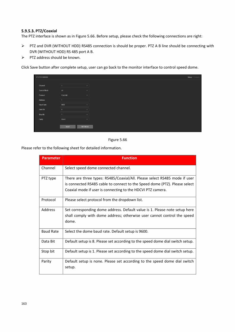
163
PTZ/Coaxial The PTZ interface is shown as in Figure 5.66. Before setup, please check the following connections are right:
➢ PTZ and DVR (WITHOUT HDD) RS485 connection is should be proper. PTZ A B line should be connecting with
DVR (WITHOUT HDD) RS 485 port A B.
➢ PTZ address should be known.
Click Save button after complete setup, user can go back to the monitor interface to control speed dome.
Figure 5.66
Please refer to the following sheet for detailed information.
Parameter Function
Channel Select speed dome connected channel.
PTZ type There are three types: RS485/Coaxial/All. Please select RS485 mode if user
is connected RS485 cable to connect to the Speed dome (PTZ). Please select
Coaxial mode if user is connecting to the HDCVI PTZ camera.
Protocol Please select protocol from the dropdown list.
Address Set corresponding dome address. Default value is 1. Please note setup here
shall comply with dome address; otherwise user cannot control the speed
dome.
Baud Rate Select the dome baud rate. Default setup is 9600.
Data Bit Default setup is 8. Please set according to the speed dome dial switch setup.
Stop bit Default setup is 1. Please set according to the speed dome dial switch setup.
Parity Default setup is none. Please set according to the speed dome dial switch
setup.

164
Account Note:
• For the character in the following user name or the user group name, system max supports 6-digits. The
space in the front or at the end of the string is null. The valid string includes: character, number, and
underline.
• The user amount default setup is 64 and the group amount default setup is 20. The factory default setup
includes two levels: user and admin. User can set the corresponding group and then set the rights for the
respective user in the specified groups.
• User management adopts group/user modes. The user name and the group name shall be unique. One user
shall be included in only one group.
5.9.5.4.1. User In this interface user can add/remove user and modify user name. Interface as shown in Figure 5.67.
Figure 5.67
Add user: It is to add a name to group and set the user rights. See Figure 5.68. There are two default users: admin
(password: admin) and hidden user “default”. Hidden user “default” is for system interior use only and cannot be
deleted. When there is no login user, hidden user “default” automatically login. User can set some rights such as
monitor for this user so that user can view some channel view without login. Here user can input the user name
and password and then select one group for current user.
Please note the user rights shall not exceed the group right setup. For convenient setup, please make sure the
general user has the lower rights setup than the admin.

165
Figure 5.68
✓ Modify user
It is to modify the user property, belonging group, password and rights. See Figure 5.69.
✓ Modify password
It is to modify the user password. User need to input the old password and then input the new password twice to
confirm the new setup. Please click the OK button to save.

166
Please note, the password ranges from 1-digit to 8-digit. It shall include the alpha-numeric and special characters.
For the user of the account rights, he can modify the password of other users.
Figure 5.69
✓ Forget Password
User can set or modify Email ID and security question if user skip these configurations at device initialization.
It will help to reset password in future if user forget the password. Interface as shown in Figure 5.70.

167
Figure 5.70
5.9.5.4.2. Group The group management interface can add/remove group, modify group password and etc. The interface is shown
as in Figure 5.71.
Figure 5.71
Add group: It is to add group and set its corresponding rights. See Figure 5.72. Please input the group name and
then check the box to select the corresponding rights. It includes: shutdown/reboot device, live view, record
control, PTZ control and etc.

168
Figure 5.72
✓ Modify group
Click the modify group button, user can see an interface is shown as in Figure 5.73. Here user can modify group
information such as remarks and rights.

169
Figure 5.73
Auto Maintain The Auto Maintain interface is shown as in Figure 5.74. Here user can select auto reboot and auto delete old files
interval from the dropdown list. If user want to use the auto delete old files function, user need to set the file
period. Click Manual reboot button, user can restart device manually.
Figure 5.74

170
Config Backup The interface is shown as in Figure 5.75
Figure 5.75
Please refer to the following sheet for detailed information.
Parameter Function
Config Import It is to import the local setup files to the system.
Config Export It is to export the corresponding WEB setup to local PC.
Default The default setup interface is shown as in Figure 5.76. Here user can select General / Encode / Record / Alarm Set
/ Network / Net Setting / GUI Display / Account / RS232. Or user can check the all box to select all items.
Figure 5.76
Upgrade The upgrade interface is shown as in Figure 5.77. Please select the upgrade file and then click the update button
to begin update. Please note the file name shall be as *.bin. During the upgrade process, do not unplug the power
cable, network cable, or shutdown the device.
➢ [Local Update] Browse firmware upgrade file and then click on Upgrade button to start upgrade process.
➢ [Online Upgrade] When the Device is connected to Internet, user can use online upgrade function to
upgrade the device.
Before using this function, user need to check if there is any new version by auto check or manual check.
• Auto check: The Device checks if there is any new version available at intervals.
• Manual check: Perform real-time check if there is any new version available.

171
Figure 5.77
Note: Please make sure power and network should not be interrupt during firmware upgrade process, neither
Device will be malfunctioned (dead condition). Improper upgrade program may also result in device malfunction!
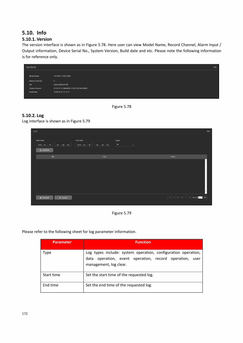
172
5.10. Info 5.10.1. Version The version interface is shown as in Figure 5.78. Here user can view Model Name, Record Channel, Alarm Input /
Output information, Device Serial No., System Version, Build date and etc. Please note the following information
is for reference only.
Figure 5.78
5.10.2. Log Log interface is shown as in Figure 5.79
Figure 5.79
Please refer to the following sheet for log parameter information.
Parameter Function
Type Log types include: system operation, configuration operation,
data operation, event operation, record operation, user
management, log clear.
Start time Set the start time of the requested log.
End time Set the end time of the requested log.

173
Parameter Function
Search
User can select log type from the drop-down list and then click
search button to view the list.
User can click the stop button to terminate current search
operation.
Detailed information User can select one item to view the detailed information.
Clear User can click this button to delete all displayed log files. Please
note system does not support clear by type.
Backup User can click this button to backup log files to current PC.
Note
• If there is no HDD, system max supports 1024 logs.
• If user have connected to the unformatted HDD, system max supports 5000 logs.
• If user have connected to the formatted HDD, system max supports 500,000 logs.
• System operation logs are saved in system memory. Other types of logs are saved in the HDD. If there is no
HDD, other types of logs are saved in the system memory too.
• The logs are safe when user format the HDD. But the logs may become loss once user removed the HDD.
5.11. Logout Click log out button, system goes back to log in interface. See Figure 5.80. User need to input user name and
password to login again.
Figure 5.80

174
Appendix A HDD Capacity Calculation Calculate total capacity needed by each DVR (WITHOUT HDD) according to video recording (video recording type
and video file storage time).
Step 1: According to Formula (1) to calculate storage capacity iq that is the capacity of each channel needed for
each hour, unit Mbyte.
102436008 = ii dq (1)
In the formula: id means the bit rate, unit Kbit/s
Step 2: After video time requirement is confirmed, according to Formula (2) to calculate the storage capacity im,
which is storage of each channel needed unit Mbyte.
= × ih× iD
(2)
In the formula:
Means the recording time for each day (hour)
Means number of days for which the video shall be kept
Step 3: According to Formula (3) to calculate total capacity (accumulation) Tq that is needed for all channels in
the DVR (WITHOUT HDD) during scheduled video recording.
=
=c
i
iT mq1 (3)
In the formula: c means total number of channels in one DVR (WITHOUT HDD)
Step 4: According to Formula (4) to calculate total capacity (accumulation) that is needed for all channels in
DVR (WITHOUT HDD) during alarm video recording (including motion detection).
=
=c
i
iT mq1 ×a% (4)
In the formula % means alarm occurrence rate
im iq
ih
iD
Tq
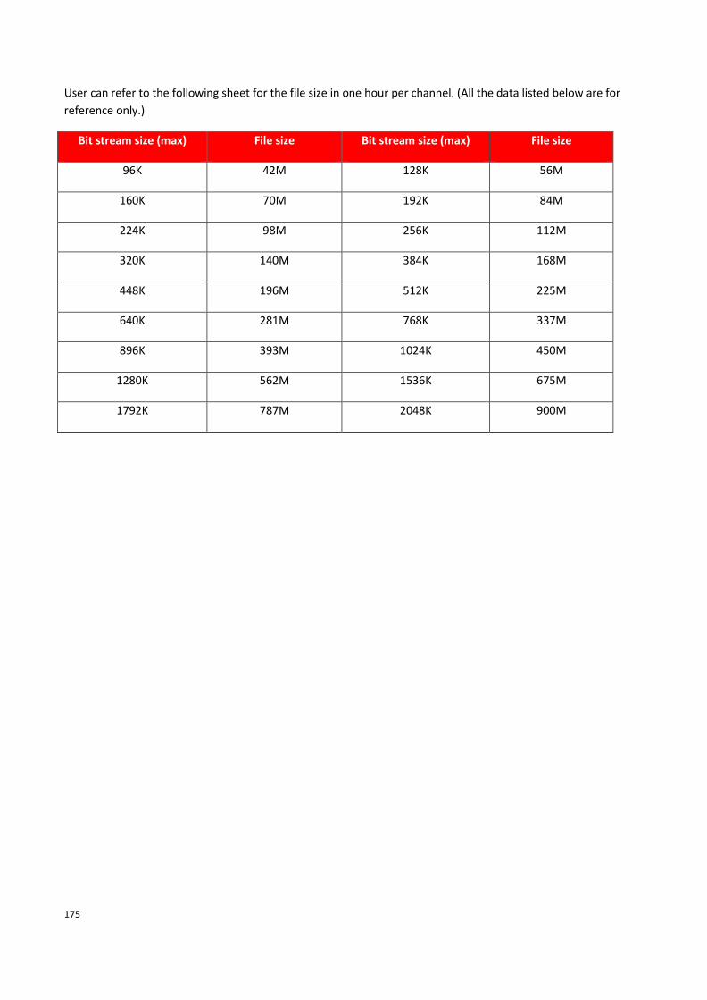
175
User can refer to the following sheet for the file size in one hour per channel. (All the data listed below are for
reference only.)
Bit stream size (max) File size Bit stream size (max) File size
96K 42M 128K 56M
160K 70M 192K 84M
224K 98M 256K 112M
320K 140M 384K 168M
448K 196M 512K 225M
640K 281M 768K 337M
896K 393M 1024K 450M
1280K 562M 1536K 675M
1792K 787M 2048K 900M

176
Appendix B Earthing
➢ What is the surge?
Surge is a short current or voltage change during a very short time. In the circuit, it lasts for microsecond. In a
220V circuit, the 5KV or 10KV voltage change during a very short time (about microseconds) can be called a surge.
The surge comes from two ways: external surge and internal surge.
⚫ The external surge: The external surge mainly comes from the thunder lightning. Or it comes from the
voltage change during the on/off operation in the electric power cable.
⚫ The internal surge: The research finds 88% of the surge from the low voltage comes from the internal of the
building such as the air conditioning, elevator, electric welding, air compressor, water pump, power button,
duplicating machine and other device of inductive load.
The lightning surge is far above the load level the PC or the micro devices can support. In most cases, the surge
can result in electric device chip damage, PC error code, accelerating the part aging, data loss and etc. Even when
a small 20 horsepower inductive engine boots up or stops, the surge can reach 3000V to 50000V, which can
adversely affect the electronic devices that use the same distribution box.
To protect the device, user need to evaluate its environment, the lighting affection degree objectively. Because
surge has close relationship with the voltage amplitude, frequency, network structure, device voltage-resistance,
protection level, ground and etc. The thunder proof work shall be a systematic project, emphasizing the all-round
protection (including building, transmission cable, device, ground and etc.). There shall be comprehensive
management and the measures shall be scientific, reliable, practical and economic. Considering the high voltage
during the inductive thundering, the International Electrotechnical Committee (IEC) standard on the energy
absorbing step by step theory and magnitude classification in the protection zone, user need to prepare multiple
precaution levels.
User can use the lightning rod, lightning strap or the lightning net to reduce the damage to the building, personal
injury or the property,
⚫ The lightning protection device can be divided into three types: Power lightning arrester: There are 220V
single-phrase lightning arrester and 380V three-phrase lightening arrester (mainly in parallel connection,
sometimes use series connection) User can parallel connect the power lightning arrester in the electric cable
to reduce the short-time voltage change and release the surge current. From the BUS to the device, there are
usually three levels so that system can reduce the voltage and release the current step by step to remove the
thunderstorm energy and guarantee the device safety. User can select the replaceable module type, the
terminal connection type and portable socket according to requirement.
⚫ Signal lightning arrester: This device is mainly used in the PC network, communication system. The
connection type is serial connection. Once user connected the signal lightning arrestor with the signal port, it
can cut the channel of the thunderstorm to the device, and on the other hand, it can discharge the current to
the ground to guarantee the device proper work. The signal lightning arrester has many specifications, and
widely used in many devices such as telephone, network, analog communication, digital communication,
cable TV and satellite antenna. For all the input port, especially those from the outdoor, user need to install
the signal lightning arrester.

177
⚫ Antenna feed cable lightning arrester: It is suitable for antenna system of the transmitter or the device
system to receive the wireless signal. It uses the serial connection too.
Please note, when you select the lighting arrester, please pay attention to the port type and the earthing
reliability. In some important environment, user need to use special shielded cable. Do not parallel connect the
thunder proof ground cable with the ground cable of the lightning rod. Please make sure they are far enough and
grounded respectively.
➢ The earthing modes
We all know the earthing is the most complicated technology in the electromagnetism compatibility design since
there is no systematic theory or module. The earthing has many modes, but the selection depends on the system
structure and performance. The following are some successfully experience from our past work.
One-point ground: In the following figure user can see there is a one-point ground. This connection provides
common port to allow signal to be transmitted in many circuits. If there is no common port, the error signal
transmission occurred. In the one-point ground mode, each circuit is just grounded only, and they are connected
at the same port. Since there is only one common port, there is no circuit and so, there is no interference.
Multiple-point ground: In the following figure, user can see the internal circuit uses the chassis as the common
point. While at the same time, all devices chassis use the earthing as the common port. In this connection, the
ground structure can provide the lower ground resistance because when there are multiple-point grounds; each
ground cable is as short as possible. And the parallel cable connection can reduce the total conductance of the
ground conductor. In the high-frequency circuit, user need to use the multiple-point ground mode and each cable
needs to connect to the ground. The length shall be less than the 1/20 of the signal wavelength.

178
Mixed ground: The mix ground consists of the feature of the one-point ground and multiple-point ground. For
example, the power in the system needs to use the one-point ground mode while the radio frequency signal
requires the multiple-point ground. So, user can use the following figure to earth. For the direct current (DC), the
capacitance is open circuit and the circuit is one-point ground. For the radio frequency signal, the capacitance is
conducive, and the circuit adopts multiple-point ground.
When connecting devices of huge size (the device physical dimension and connection cable is big comparing with
the wave path of existed interference), then there is possibility of interference when the current goes through the
chassis and cable. In this situation, the interference circuit path usually lies in the system ground circuit.
When considering the earthing, user need to think about two aspects: The first is the system compatibility, and
the other is the external interference coupling into the earth circuit, which results in system error. For the
external interference is not regular, it is not easy to resolve.
➢ Thunder proof ground method in the monitor system
⚫ The monitor system shall have sound thunder proof earthing to guarantee personnel safety and device
safety.
⚫ The monitor system working ground resistance shall be less than 1Ω.
⚫ The thunder proof ground shall adopt the special ground cable from the monitor control room to the ground
object. The ground cable adopts copper insulation cable or wire and its ground section shall be more than
20mm2.
⚫ The ground cable of the monitor system cannot short circuit or mixed connected with the strong alternative
current cable.
⚫ For all the ground cables from the control room to the monitor system or ground cable of other monitor
devices, please use the copper resistance soft cable and its section shall be more than 4mm2.
⚫ The monitor system usually can adopt the one-point ground.
⚫ Please connect the ground end of 3-pin socket in the monitor system to the ground port of the system
(protection ground cable)

179
➢ The shortcut way to check the electric system using the digital multimeter
For 220V AC socket, from the top to the bottom, E (ground cable), N (neutral cable), L (live cable). Please refer to
the following figure.
There is a shortcut way to check these thee cables connection are standard or not (not the accurate check).
Importance
In the following operations, the multimeter range shall be at 750V!
For E (earth cable)
Turn the digital multimeter to 750V AC, use one hand to hold the metal end, and then the other hand inserts the
pen to the E port of the socket. See the following figure. If the multimeter shows 0, then user can see current
earth cable connection is standard. If the value is more than 10, then user can see there is inductive current, and
the earth cable connection is not proper.

180
For L (live cables)
Turn the digital multimeter to 750V AC, use one hand to hold the metal end, and then the other hand inserts the
pen to the L port of the socket. See the following figure. If the multimeter shows 120, then user can see current
live cable connection is standard. If the value is less than 60, then user can see current live cable connection is
not proper or it is not the live cable at all.
For N (Neutral cable)
Turn the digital multimeter to 750V AC, use one hand to hold the metal end, and then the other hand inserts the
pen to the N port of the socket. See the following figure. If the multimeter shows 0, then user can see current N
cable connection is standard. If the value is more than 10, then user can see there is inductive current, and the
neutral cable connection is not proper. If the value is 120, then user can know misconnected the neutral cable to
the live cable.

181
Note:
⚫ This manual is for reference only. Slight difference may be found in the user interface.
⚫ All the designs and software here are subject to change without prior written notice.
⚫ All trademarks and registered trademarks mentioned are the properties of their respective owners.
⚫ If there is any uncertainty or controversy, please refer to the final explanation of us.
⚫ Please visit our website or contact local retailer for more information.

182
Thank You for Choosing CP Plus!
Website: - www.cpplusworld.com
Email id: - [email protected] [email protected]


