25
SMT 6065 User Manual Version 4.0 SMT 6065 User Manual Version 4.0 26/5/07. Sundance Asia Ltd. Inc. ©

SMT 6065 User Manual
Version 4.0
SMT 6065 User Manual Version 4.0 26/5/07.
Sundance Asia Ltd. Inc. ©

Revision History Date Comments Engineer Version
15-1-06 Original Document WD 1.0
15-4-06 Sample Program PD 1.1
09-05-07 Remove DriverBuilder PD 2.1
26-05-07 Add Revision History PD 2.2
26-05-07 Setup for VxWorks5.5 PD 3.0
26-05-07 Setup for VxWorks6.3 PD 4.0

Table of content
Table of content.................................................................................................................................3 List of figures....................................................................................................................................5 List of Abbreviations and Conventions.............................................................................................6 Abbreviations...................................................................................................................................6 Conventions .....................................................................................................................................6
1 Introduction...............................................................................................................................7 1.1 SMT6065 Features ........................................................................................................7 1.2 Supported Carrier Boards..............................................................................................8
2 Getting Started ..........................................................................................................................9 2.1 Prerequisites ..................................................................................................................9 2.2 Software Installation .....................................................................................................9
3 Hardware Overview ..................................................................................................................9 3.1 Comport ......................................................................................................................10 3.2 CPLD ..........................................................................................................................10 3.3 State of IIOF Lines......................................................................................................11 3.4 The PCI Bridge Chip...................................................................................................11
4 Software Design......................................................................................................................11 4.1 Interface Mechanism...................................................................................................11
5 Functions exported by SmtDrv.out .........................................................................................12 5.1 SmtOpen......................................................................................................................12 5.2 SmtClose .....................................................................................................................13 5.3 SmtGetBoardCount .....................................................................................................13 5.4 SmtOpenBoard............................................................................................................13 5.5 SmtCloseBoard ...........................................................................................................13 5.6 SmtGetBoardIndex......................................................................................................14 5.7 SmtGetBoardInfo ........................................................................................................14 5.8 SmtGetError ................................................................................................................15
6 Functional Description............................................................................................................16 6.1 Host Comport ..............................................................................................................16 6.1.1 CpRead............................................................................................................17 6.1.2 CpWrite...........................................................................................................17 6.1.3 CpCancel .........................................................................................................17
6.2 Downloading Files ......................................................................................................18 6.2.1 BinaryLoad......................................................................................................18
6.3 Mailboxes....................................................................................................................18 6.3.1 MbWrite ..........................................................................................................19 6.3.2 MbRead...........................................................................................................20 6.3.3 MbCancel ........................................................................................................20
6.4 Board State ..................................................................................................................20 6.4.1 ResetTIMs.......................................................................................................20 6.4.2 ResetBoard ......................................................................................................21

6.5 Carrier Board Registers Access...................................................................................21 6.5.1 Read32 ............................................................................................................21 6.5.2 Read16 ............................................................................................................21 6.5.3 Read8 ..............................................................................................................21 6.5.4 Write32............................................................................................................22 6.5.5 Write16............................................................................................................22 6.5.6 Write8..............................................................................................................22
6.6 PCI Bridge Register Access ........................................................................................22 6.6.1 PciRead32 .......................................................................................................23 6.6.2 PciWrite32 ......................................................................................................23 6.6.3 PciWrite16 ......................................................................................................23 6.6.4 PciWrite8 ........................................................................................................23
6.7 DSP Interrupt ..............................................................................................................23 6.7.1 DspAttatchInt ..................................................................................................24
7 Error handling .........................................................................................................................24 7.1 Exported Functions .....................................................................................................24 7.2 Exception Mechanism.................................................................................................25

List of figures
Figure 1 - The SMT6065 interfaces to Sundance hardware ............................................................7 Figure 2 - Overview of the hardware. ............................................................................................10 Figure 3 - Mailboxes with the SMT6065 ......................................................................................19

List of Abbreviations and Conventions
Abbreviations
BAR Base Address Region
COFF Common Object File Format
CPLD Complex PLDs
DMA Direct Memory Access
DSP Digital Signal Processor
HSC High Speed Channel
JTAG Joint Test Action Group
MDL Memory Descriptor List
PCI Peripheral Component Interconnect
PLD Programmable Logic Device
SMT Sundance Multiprocessor Technology Ltd.
TIM Texas Instruments Module
Conventions
UINT A 32 bit unsigned value (unsigned int).
DWORD 32 bit unsigned value (unsigned long).
Root TIM The TIM on site 1 of your carrier board.
Root DSP The DSP on TIM site 1.

1 Introduction
1.1 SMT6065 Features
The SMT6065 SDK provides you with an easy and efficient way to access Sundance Carrier Boards, under OS VxWorks 6.3. It allows you to control these boards from the host as well as to exchange data between the carrier board and the host. The SMT6065 is ideal for customers that wish to develop their own code to interface with Sundance hardware, under OS VxWorks 6.3.
Sundance Carrier board
SMT6065 SDK
Your application
Comport PCIStatus Status Control
Figure 1 - The SMT6065 interfaces to Sundance hardware
Figure 1 - shows the SMT6065 forming the link between your application and the Sundance carrier boards in your system. Having a standard interface such as the SMT6065 ensures that you do not need to recompile and link your software when the hardware in the system changes. The SMT6065 hides the details of the device driver, allowing you to concentrate on the development process. The SMT6065:
Shorten development time by providing you with a ready-to-use interface to the hardware.
Transfers data between the carrier board and the host. Downloads applications to the carrier board. Obtains information about the carrier board.

Controls the state of the carrier board. Gives you a basic building block for more complex systems. Provides you with direct access to the hardware registers of the carrier board. Provides you with a C++ type interface to the carrier board. For OS VxWorks 6.3.
1.2 Supported Carrier Boards
The SMT6065 currently supports the following carrier boards. Carrier board Description Functionality SMT300 1 TIM site Compact PCI carrier board Full support SMT300Q 4 TIM site Compact PCI carrier board Full support SMT310 1 TIM site PCI carrier board Full support SMT310Q 4 TIM site PCI carrier board Full support

2 Getting Started
2.1 Prerequisites
The language C++ is used for the software interfaces. Even if you are not familiar with C++, you should be able to find your way by referring to the samples. The samples have been compiled and tested with Wind Rriver Bench 2.5 © and VxWorks 6.3 ©.
2.2 Software Installation
In order to install the SMT6065 SDK, you need to take the following three steps. 1) Build VxWorks system
i. Before build VxWorks system, please add cSmtPciInit.c into the VxWorks system project.
ii. Modify the file prjConfig.c with the function usrRoot(……), call cSmtPciInit() before calling usrMmuInit(……), such as the following:
In the file prjConfig.c: void usrRoot(……) { …… cSmtPciInit(); usrMmuInit(……); …… }
2) Load SMT6065 driver
Load the file SmtDrv.out from the WindShell ld < SmtDrv.out
3) Run the sample program to check if the SDK environment is installed correctly. Load the file CpTest.out from the WindShell ld < CpTest.out => main()
3 Hardware Overview
You need to be aware of the assumptions the SMT6065 makes about hardware resources. This section provides a basic overview of the main hardware features

and shows how the SMT6065 interacts with them. The carrier board’s User Manual contains a more detailed description of the hardware.
Figure 2 - Overview of the hardware.
The figure above illustrates the main hardware concepts of a typical Sundance carrier board.
3.1 Comport
A comport is a general mechanism for transferring data between components of your system. Most TIM modules have several comports that can connect to other TIMs or the host. These connections are usually made with FMS cables, but some boards have built-in connections that can be controlled by carrier board registers; the User Manual for your board will describe these registers in detail. The standard board configuration will connect comport 3 on TIM site 1 to the host.
3.2 CPLD
The CPLD is used to configure the carrier board. It allows you to select the direction of signals on the carrier board, select interrupt sources and set the routing of the IIOF lines. The CPLD registers are mapped in BAR1 of the PCI bridge chip. The carrier board’s User Manual gives more information about the CPLD.

3.3 State of IIOF Lines
The LINT (local interrupt) line on the global bus side of the PCI bridge chip can be switched to any of the IIOF lines that go to the DSP. The initial configurations of the IIOF lines are as follows:
Line Use or direction
IIOF0 Host to DSP
IIOF1 DSP to Host
IIOF2 Used internally by the SMT6065 to signal mailbox interrupts to the DSP.
3.4 The PCI Bridge Chip
The bridge chip forms the link between the host and the carrier board. It connects the local bus on the carrier board with the PCI bus of the host and provides apertures that allow the local bus access to the PCI bus. These apertures act like windows through which the local bus can access data on the PCI bus. The internal PCI bridge registers are mapped in BAR0, allowing access by both the local bus (DSP side) and the PCI bus (host side). Contained in the bridge chip are the 16 x 8-bit mailbox registers (Section 13). The bridge chip provides a local bus interrupt line (LINT) as well as a PCI bus interrupt line (IntA). These interrupt lines allow both the host and the DSP to interrupt each other. More information about the bridge chip can be found at http://www.quicklogic.com.
4 Software Design
The design of the SMT6065 allows developers to: Obtain a simple interface for controlling the host comport, Mailboxes, and DSP
interrupts. Access the low-level functionality of the hardware.
4.1 Interface Mechanism
The design makes use of a C++ style interface pointer to the hardware. SmtDrv.out exports functions that gather information about the installed boards

and provide an interface pointer for later use. To use the SMT6065, you need to:
Build a VxWorks system, and modify the function usrRoot(……) perfectly, calling cSmtPciInit(……) before calling usrMmuInit(……).
Load the object file SmtDrv.out. Obtain an interface pointer to the hardware by calling SmtOpenBoard(). Use the interface pointer to call functions related to the hardware.
Example:
IFHw *pBoard = SmtOpenBoard(0); // open the first board found
pBoard->ResetTIMs(); pBoard->BinaryLoad("MyFile.app");
5 Functions exported by SmtDrv.out
This section describes each of the functions exported by SmtDrv.out. These functions are described in the header file SmtDrv.h:
SmtOpen SmtClose SmtGetBoadrCount SmtOpenBoard SmtCloseBoard SmtGetBoardIndex SmtGetBoardInfo SmtGetError
5.1 SmtOpen
Initialize the SMT6065 library. Applications must call this function before using any other features of the library.
Prototype SMTRet SmtOpen( void );
Return value
The function returns SMT_OK on successful completion; other return values indicate failure. SmtGetError() can be used to translate error values into descriptive strings.

5.2 SmtClose
Close the SMT6065 library.
Prototype void SmtClose(void);
5.3 SmtGetBoardCount
Return the number of Sundance carrier boards found in the system.
Prototype DWORD SmtGetBoardCount(void);
Return value
The number of Sundance carrier boards found in the system.
5.4 SmtOpenBoard
Obtain an interface to a Sundance carrier board.
Prototype IFHw * SmtOpenBoard( UINT nIndex );
Parameters
nIndex The zero based index of the carrier board. nIndex should be in the range 0 <= nIndex < GetBoardCount().
Return value
The return value is an interface of type IFHw that can be used to access the carrier board. Refer to section 10 for a description of the functions provided by this interface. NULL (0) is returned on error.
5.5 SmtCloseBoard
Close an interface to a board. You should not use the interface pointer any more after calling SmtCloseBoard().

Prototype void SmtCloseBoard( UINT nBoard );
Parameters
nBoard The index of the board that should be closed. nIndex should be in the range 0 <= nIndex < GetBoardCount().
5.6 SmtGetBoardIndex
Find the zero based index for the board at the specified base address.
Prototype INT SmtGetBoardIndex( UINT nBaseAddress );
Parameters
nBaseAddress The board base address. The base address is the PCI address that the host operating system has assigned to the carrier board.
Return value
The zero based index of the board at base address nBaseAddress.
The function returns –1 when no board is found.
5.7 SmtGetBoardInfo
Return information about a carrier board. For a description of the information returned see the remarks.
Prototype SMTRet SmtGetBoardInfo( UINT nIndex, SMTBI& info );
Parameters
nIndex The zero based index of the board.
info The structure that is to be filled in with the board information.
Return value
The function returns SMT_OK on successful completion; other return values indicate failure. SmtGetError() can be used to translate error values into descriptive strings.

Remarks
The information is returned in the SMTBI structure described below: struct SMTBI {
SMTBoardType Type;
char cszType[32];
UINT nBase;
UINT nRange;
SMTHWStatus HwStatus;
SMTLock LockStatus;
SMTOpen OpenRes;
};
The information returned is summarized in the table below:
Field Description
Type Specify the type of carrier board.
cszType String description of the type of carrier board. For example “SMT310Q”
nBase The PCI base address that the host operating system has assigned to this carrier board.
nRange The number of bytes from the base address that has been assigned to this carrier board.
HwStatus The hardware status of the carrier board. Valid values are SMT_On and SMT_Off.
LockStatus If the carrier board could be opened successfully, this value will be SMT_LOCK_OK.
OpenRes If the software was initialized correctly, this value will be SMT_OPEN_OK.
5.8 SmtGetError
Return a string description the error value.
Prototype: const char * SmtGetError( SMTRet Error );
Parameters:
Error The error value.
Return value:

A textual translation of the error value.
6 Functional Description
Once an interface to the hardware has been obtained by calling SmtOpenBoard(), the interface allows you to access the following features available on various Sundance carrier boards.
Functionality SMT300-300Q-310-310Q
Comport access Supported
Downloading files Supported
Mailboxes Supported
High speed channel NOT Supported
Board state Supported
Read and write carrier board registers Supported
PCI bridge chip register access Supported
DSP Interrupt Supported
6.1 Host Comport
The simplest and most general I/O mechanism that can be used to communicate between the host and the Root DSP is the host comport. It is a sequential, bi-directional link that gives typical transfer speeds of up to 2MB/s. It is also used for loading programs into the DSP. Refer to the user
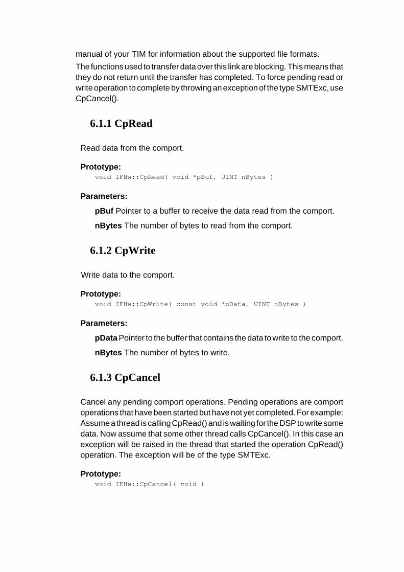
manual of your TIM for information about the supported file formats. The functions used to transfer data over this link are blocking. This means that they do not return until the transfer has completed. To force pending read or write operation to complete by throwing an exception of the type SMTExc, use CpCancel().
6.1.1 CpRead
Read data from the comport.
Prototype: void IFHw::CpRead( void *pBuf, UINT nBytes )
Parameters:
pBuf Pointer to a buffer to receive the data read from the comport.
nBytes The number of bytes to read from the comport.
6.1.2 CpWrite
Write data to the comport.
Prototype: void IFHw::CpWrite( const void *pData, UINT nBytes )
Parameters:
pData Pointer to the buffer that contains the data to write to the comport.
nBytes The number of bytes to write.
6.1.3 CpCancel
Cancel any pending comport operations. Pending operations are comport operations that have been started but have not yet completed. For example: Assume a thread is calling CpRead() and is waiting for the DSP to write some data. Now assume that some other thread calls CpCancel(). In this case an exception will be raised in the thread that started the operation CpRead() operation. The exception will be of the type SMTExc.
Prototype: void IFHw::CpCancel( void )

6.2 Downloading Files
The host comport is the standard route for loading programs into your DSP network. Each TIM in your system will load a “bootloader” from its flash ROM when it comes out of reset. This “bootloader” performs various housekeeping operations to initialize the TIM and then waits until data arrives on any of its comports. The first comport to become active is selected and the data it provides are loaded into the DSP and executed. The host comport only gives you access to the Root TIM of your DSP board. You must load any other TIMs in your system indirectly via the root with explicit code. This is done automatically if you are loading a 3L Diamond application.
6.2.1 BinaryLoad
The contents of the specified file will be sent down the host link unchanged, one 32-bit word at a time. Each 32-bit word is constructed from four bytes in the file, the least significant byte coming first. This function is most commonly used to load Diamond .app files that contain information allowing all processors in a network to be loaded. It is important that the file you specify be a multiple of 4 bytes in size. If this is not the case, the function will round the size down to the nearest four bytes, and remaining bytes will not be sent to the DSP.
Prototype: void IFHw::BinaryLoad( const char *pcszFilename, PrgssInd
*pProgress = 0 )
Parameters:
pcszFilename The filename of the binary file to download to the Root DSP.
pProgress Pointer to a structure that will obtain progress reports during the download. If this value is zero, no progress is reported.
6.3 Mailboxes
The mailboxes provided by the PCI bridge chip allow the host and the Root DSP to signal each other with information. Note that mailboxes are intended as a signaling mechanism and not as a way

of passing large amounts of data. The V3 bridge chip provides 16 x 8-bit mailboxes. These mailboxes are combined to form two independent 32-bit, bi-directional mailboxes. These mailboxes are numbered 0 and 1.
Figure 3 - Mailboxes with the SMT6065
IMPORTANT: Mailbox 1 is used internally by the HSC, leaving only Mailbox 0 available to user applications. The V3 bridge chip uses interrupts to notify both the PCI and the local bus side of mailbox activity. The SMT6065 configures these interrupts to provide blocking mailbox read and write functions on the host. These functions will block until the DSP performs the required action. When the host side writes to a mailbox, the write function will block (wait) until the DSP side had read the mailbox value. Similarly when the host reads a mailbox, the function will block until the DSP writes a mailbox value. The host CPU usage is virtually zero during function blocking, as the blocking behaviour of the mailbox functions is achieved by the use of interrupts. Although you are free to develop your own mailbox code on the DSP side, we recommend you use 3L Diamond © on the DSP side, as it provides built-in support for the mailboxes.
6.3.1 MbWrite
Write a value to a mailbox.

Prototype void IFHw::MbWrite( UINT nBox, DWORD dwValue )
Parameters
nBox The target mailbox. Must be zero.
dwValue The value to write to the mailbox.
6.3.2 MbRead
Read a value from a mailbox.
Prototype DWORD IFHw::MbRead( UINT nBox )
Parameters
nBox The target mailbox. Must be zero.
6.3.3 MbCancel
Cancel a pending mailbox operation. The thread waiting on a pending mailbox operation will throw an exception of the type SMTExc when MbCancel() is called.
Prototype void IFHw::MbCancel( UINT nBox )
Parameters
nBox The target mailbox. Must be zero.
6.4 Board State
You usually need to reset the TIMs on the carrier board before downloading your application.
6.4.1 ResetTIMs
Reset the TIMs on the carrier board.
Prototype void IFHw::ResetTIMs(void)

6.4.2 ResetBoard
Reset the carrier board. This function resets the TIMs and the JTAG controller.
Prototype void IFHw::ResetBoard(void)
6.5 Carrier Board Registers Access
The SMT6065 gives you an access to the carrier board’s registers to enable you to perform any low level accesses that you might require. Refer to the carrier board’s user manual for a description of the carrier board registers and BAR address mapping. The register access is specified by a BAR address and offset values. For the following functions, the number at the end of the function name indicates the number of bits that are to be read or written. For each function: nBar BAR to use. nOffset Offset into the BAR to access.
6.5.1 Read32
Read 32 bits from the address specified.
Prototype DWORD IFHw::Read32( UINT nBar, UINT nOffset )
6.5.2 Read16
Read 16 bits from the address specified.
Prototype DWORD IFHw::Read16( UINT nBar, UINT nOffset )
6.5.3 Read8
Read 8 bits from the address specified.
Prototype DWORD IFHw::Read8( UINT nBar, UINT nOffset )

6.5.4 Write32
Write 32 bits to the address specified.
Prototype void IFHw::Write32( UINT nBar, UINT nOffset, DWORD dword
6.5.5 Write16
Write 16 bits to the address specified.
Prototype void IFHw::Write16( UINT nBar, UINT nOffset, WORD word )
6.5.6 Write8
Write 8 bits to the address specified.
Prototype void IFHw::Write8( UINT nBar, UINT nOffset, BYTE byte )
6.6 PCI Bridge Register Access
The Sundance carrier boards use a V3 bridge chip to interface to the PCI bus. Certain resources are assigned to the carrier board when the host boots. These resources include I/O address range, memory range and interrupt resources. Information about these resources is kept in the PCI bridge chip registers. The PCI bridge chip registers hold setup and control values and implement the mailbox registers. Although direct access to the mailbox registers (offset 0XC0 – 0xCF) is possible, it is strongly recommended that you use the SMT6065’s built-in support (see section 13). This is a consequence of the design of the interrupt service routine used by the SMT6065. A special bus cycle on the PCI bus is used to access the PCI registers of the carrier board. This special bus cycle does not make use of the BAR mapping, and is therefore safe to use even if the BAR addresses have not been set up. You should not need direct access to the PCI registers for most systems. Please make sure that you know what you are doing before accessing the PCI bridge chip registers. Writing incorrect values to these registers will almost certainly crash the host.

For a detailed description of the PCI bridge chip registers, refer to the user manual for the bridge chip. http://www.quicklogic.com. The number at the end of the following function names indicates the number of bits being read or written.
6.6.1 PciRead32
Read 32 bits from the PCI register specified.
Prototype DWORD IFHw::PciRead32( DWORD dwReg)
6.6.2 PciWrite32
Write 32 bits to the PCI register specified.
Prototype void IFHw::PciWrite32(DWORD dwReg, DWORD dwValue )
6.6.3 PciWrite16
Write 16 bits to the PCI register specified.
Prototype void IFHw::PciWrite16( DWORD dwReg, WORD wValue )
6.6.4 PciWrite8
Write 8 bits to the PCI register specified.
Prototype void IFHw::PciWrite8( DWORD dwReg, BYTE cValue )
6.7 DSP Interrupt
The DSP (C40) interrupt is a mechanism that was inherited from a previous generation of carrier boards and is still supported in the current generation. The DSP interrupt allows the DSP to interrupt the host. The DSP can generate a DSP interrupt to the host by toggling the IIOF1 line. The SMT6065 allows you to attach an interrupt function to this event. Unlike mailboxes, no data is transferred with this type of interrupt.
Refer to the samples for the DSPInt interrupt sample.
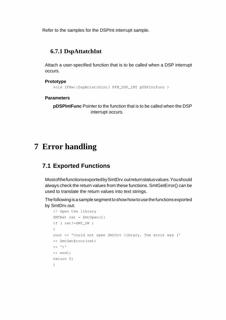
6.7.1 DspAttatchInt
Attach a user-specified function that is to be called when a DSP interrupt occurs.
Prototype void IFHw::DspAttatchInt( PFN_DSP_INT pDSPIntFunc )
Parameters
pDSPIntFunc Pointer to the function that is to be called when the DSP interrupt occurs.
7 Error handling
7.1 Exported Functions
Most of the functions exported by SmtDrv.out return status values. You should always check the return values from these functions. SmtGetError() can be used to translate the return values into text strings.
The following is a sample segment to show how to use the functions exported by SmtDrv.out.
// Open the library
SMTRet ret = SmtOpen();
if ( ret!=SMT_OK )
{
cout << "Could not open SmtDrv library. The error was ("
<< SmtGetError(ret)
<< ")"
<< endl;
return 0;
}
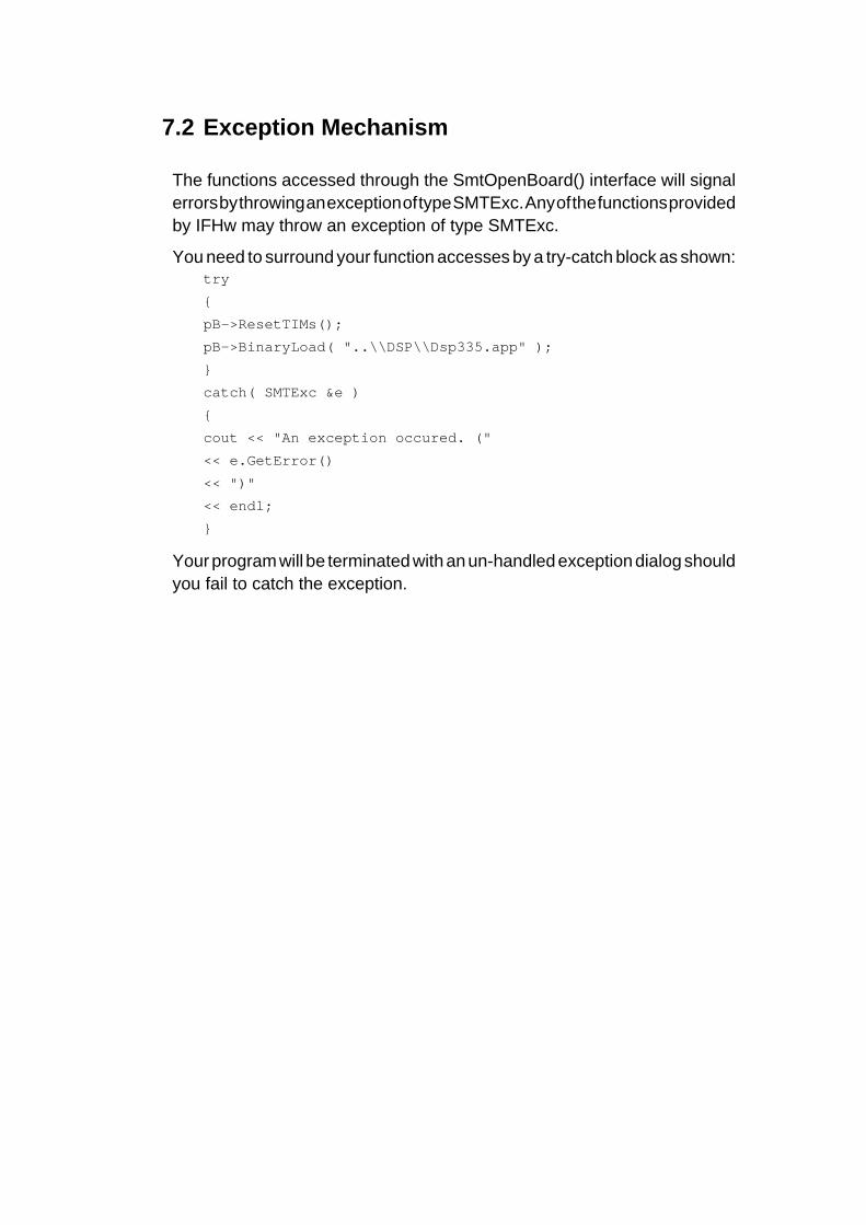
7.2 Exception Mechanism
The functions accessed through the SmtOpenBoard() interface will signal errors by throwing an exception of type SMTExc. Any of the functions provided by IFHw may throw an exception of type SMTExc.
You need to surround your function accesses by a try-catch block as shown: try
{
pB->ResetTIMs();
pB->BinaryLoad( "..\\DSP\\Dsp335.app" );
}
catch( SMTExc &e )
{
cout << "An exception occured. ("
<< e.GetError()
<< ")"
<< endl;
}
Your program will be terminated with an un-handled exception dialog should you fail to catch the exception.


