User manual Version 3.0 (04/2013) en Translation of the original instructions Interroll RollerDrive BT100 Chapter-ID: User manual Chapter-ID: Version Chapter-ID: Translation of the original instructions
Transcript
User manual
Interroll RollerDriveBT100Chapter-ID: User manualChapter-ID: VersionChapter-ID: Translation of the original instructions
CopyrightThe copyright of this manual remains with Interroll Engineering GmbH. The operating instructions contain technical regulations and drawings which may not be reproduced partially or in full, transmitted by any means, utilized without permission for competitive purposes or disclosed to third parties.
Contents This manual contains important advice, notes and information about the RollerDrive BT100 in all phases of its lifecycle:• Transport, assembly and start-up• Safe operation, maintenance and troubleshooting, disposal• Accessories
Validity of the manual The manual describes the RollerDrive BT100 as it is delivered by Interroll.
In addition to this manual, special contractual agreements and technical documents apply to special versions.
The manual is part of theproduct
For trouble-free, safe operation and warranty claims, read the manual and follow the instructions before handling the RollerDrive BT100.
Keep the manual near to the RollerDrive BT100. Pass the manual on to any subsequent operator or occupant of the
RollerDrive BT100. Interroll does not accept any liability for malfunctions or defects due to non-
observance of this manual. If you have any questions after reading the operation manual, feel free to
contact our customer service. See the last page for your local contact.
Warnings in this manual
The warnings in this document refer to risks which may arise while using the RollerDrive BT100. For relevant warnings, see "Safety", page 4 and the warnings at the beginning of each chapter.
There are three categories of danger. The following signal words are used in the document as required:• Danger • Warning• Caution
Signal word Meaning
Danger Indicates a hazardous situation which, if not avoided, will result in death or serious injury.
Warning Indicates a hazardous situation which, if not avoided, could result in death or serious injury.
Caution Indicates a hazardous situation which, if not avoided, may result in minor or moderate injury.
2 Version 3.0 (04/2013) en
Translation of the original instructions
RollerDrive BT100
Introduction
Structure of warnings
Further symbols
This symbol marks the steps that have to be carried out.
Nature and source of the hazardPossible consequence of non-observance
Information about how to avoid the hazard.
DANGER
This symbol identifies possible material damage. Information about how to avoid damage.
Important
This symbol displays safety instructions.Hint
This symbol marks useful and important information.
3Version 3.0 (04/2013) en
Translation of the original instructions
RollerDrive BT100
Safety
General safety instructions
The RollerDrive BT100 is designed according to the technical state of the art and is reliable in operation, once distributed. However, risks may still arise.• Risks of physical injury to the user or bystanders.• Adverse effects of the RollerDrive and other material.
Always read the entire operating and safety instructions before starting to work with the RollerDrive and follow the information contained herein in full.
Only instructed and qualified persons may work with the RollerDrive. Always keep this user manual at hand when working on the RollerDrive so
that you can consult it quickly if required. Always comply with relevant national safety regulations. If you have any questions after reading this user manual, feel free to contact
our customer service. See the last page for contact information.
Intended use
The RollerDrive BT100 may only be used for industrial applications and in an industrial environment to convey goods such as parts, cartons, totes or boxes. It must be integrated in a conveyor module or a conveying system. Any other use is not permitted.
Any changes that affect the safety of the product are not allowed.
The RollerDrive BT100 may only be used within the given operation limits.
Unintended use
The RollerDrive BT100 may not be used to transport persons, bulk cargo or small parts.
The RollerDrive is not intended for use under impact or shock loads.
Applications not according to the intended use of the RollerDrive BT100 require approval from Interroll.
Important
Disregarding the warnings in this manual may lead to serious injury.
4 Version 3.0 (04/2013) en
Translation of the original instructions
RollerDrive BT100
Safety
Qualified persons
Qualified persons are persons who read and understand the manual and, taking national regulations into account, can competently execute incidental work.
Only instructed and qualified persons may work with the RollerDrive, taking the following into account:• the relevant manuals and diagrams,• the warning and safety instructions in this manual,• the system specific regulations and requirements,• national or local regulations and requirements for safety and accident
prevention.
Dangers
Persons Maintenance or repair work must only be executed by authorized and qualified persons in accordance with the applicable regulations.
Before turning on the RollerDrive, ensure that no unauthorized persons are near the conveyor.
Electricity Only perform installation and maintenance work after you have switched off the power. Ensure that the RollerDrive cannot be turned on accidentally.
Rotating parts Keep your fingers and hair away from moving parts. If you have long hair, always wear a hair net. Never wear loose clothing. Never wear jewellery, such as necklaces or bracelets. Wear safety shoes.
Working environment Do not use the RollerDrive in explosive atmospheres. Always remove materials and objects which are not required from the work
area. Wear safety shoes. Regulate and monitor careful placement of the goods on the conveyor.
Malfunctioning duringoperation
Regularly check the RollerDrive for visible damage. In case of fumes, unusual noise or blocked or damaged goods, stop the
RollerDrive at once and ensure that the RollerDrive cannot be started accidentally.
Contact qualified personnel immediately to find the source the malfunction. Do not step on the RollerDrive during operation.
Maintenance As the product is maintenance free, you only need to check regularly for visible damages, unusual noise and that the screws and nuts are still tightened.
Do not open the RollerDrive.
Accidental start-up Make sure that the RollerDrive cannot start up accidentally, particularly during assembly, maintenance work and in the event of a fault.
Important
The following list informs you about the various types of danger or damage that may occur while working with the RollerDrive BT100.
5Version 3.0 (04/2013) en
Translation of the original instructions
RollerDrive BT100
Safety
Interfaces
By assembling the RollerDrive in a conveyor module, potential hazards may occur. These are not described in this manual and have to be analyzed during the design, installation, and startup of the conveyor module.
After assembling the RollerDrive in a conveyor module, check the whole system for any new potential dangerous condition prior to turning on the conveyor.
Operating modes
Normal mode Operation of the installed device at the end customer's as a component in a conveyor in a complete system.
Special mode All operating modes which are required to guarantee and maintain safe and normal operation.
Special operating mode Explanation Comment
Transport/Storage Loading and unloading, transport and storage
-
Assembly/Initial start-up Installation at the end customer's and performing the test run
When de-energized
Cleaning External cleaning When de-energized
Maintenance/Repairs Maintenance and inspection tasks When de-energized
Troubleshooting Troubleshooting in the event of a fault When de-energized
Fault elimination Eliminating the fault When de-energized
Shut-down Dismantling from the conveyor When de-energized
Disposal Disposal of RollerDrive and packaging -
6 Version 3.0 (04/2013) en
Translation of the original instructions
RollerDrive BT100
Product information
Components
Product description
The RollerDrive BT100 is an electrically driven roller. It replaces external components such as motors and gears, which require frequent maintenance.
The RollerDrive BT100 can be used in dusty and/or moist environments due to its protection class IP54.
The RollerDrive BT100 is powered by a brushed, mechanically commutated 24 VDC motor.
Overload protection device Thermal protection against permanent overload with temperature switch: A temperature switch (bimetal switch) is installed on the brush bridge. This switches off the RollerDrive when the temperature of the motor winding exceeds 110 °C (230 °F). When the motor winding has cooled down again to approx. 90 °C (194 °F), the RollerDrive is switched back on again. Since the switch is not located directly in the winding, it takes a certain time until a temperature increase reaches the switch. If the roller is blocked immediately after the first switching on [at a temperature of 20 °C (68 °F)], there is a risk of the motor winding being burned through. A slow-blow 2A fuse can therefore also be used as an additional, faster fuse safeguard.
If the RollerDrive is over-stressed by increased friction, excessive load, too many cycles etc., it is automatically switched off by the overload protection. After cooling down, the RollerDrive starts up again automatically without a reset. If the overload persists, the motor switches itself off again. If there in no overload, it continues to run normally.
1 Motor cable2 Motor cartridge shaft3 Fixed bearing housing assembly4 Motor5 Idler cartridge shaft
Mechanical performance, performance data and performance charts are on basis of 20 °C (68 °F).
9Version 3.0 (04/2013) en
Translation of the original instructions
RollerDrive BT100
Product information
Performance data
Motor cable and plug
The RollerDrive BT100 is available in two versions:• Motor cable• Motor plug with grommet
Motor cable
Motor plug with grommet The motor plug for the RollerDrive BT100 is "CST-100-2 + Contact", manufactured by AMP.
This version is dedicated to easy Z-Card connection.
DriveControl for the RollerDrive BT100
Interroll recommends using the RollerDrive BT100 in conjunction with the Interroll Z-Card BT Easy.
Gear ratio 9:1 9:1reduced
21:1 30:1 37:1 37:1reduced
Rated torque 0.45 Nm (4.0 in-lbf)
0.7 Nm (6.2 in-lbf)
0.84 Nm (7.4 in-lbf)
1.28 Nm (11.3 in-lbf)
1.64 Nm (14.5 in-lbf)
2.5 Nm (22.1 in-lbf)
Start-up torque 1.9 Nm (17.2 in-lbf)
2.6 Nm (23.0 in-lbf)
3.0 Nm (26.6 in-lbf)
4.4 Nm (38.4 in-lbf)
6.6 Nm (58.4 in-lbf)
6.4 Nm (56.6 in-lbf)
Rated speed 0.90 m/s (177 fpm)
0.70 m/s (138 fpm)
0.40 m/s (79 fpm)
0.30 m/s (59 fpm)
0.20 m/s (39 fpm)
0.10 m/s (20 fpm)
Pin Color Lead
1 White 24 VDC
2 Brown Ground
12
Pin Color Lead
1 Red 24 VDC
2 Black Ground
1
2
10 Version 3.0 (04/2013) en
Translation of the original instructions
RollerDrive BT100
Product information
Dimensions of the motor shaft
Standard configuration
Standard configuration for Z-Card connection
FTM8 configuration
19.5 mm (0.77 in)
13.5 mm (0.53 in)
5000 mm (197 in)
6 mm (0.24 in)
Hex shaft AF 11 mm (0.44 in)
M12 x 1.5 mm
1000 mm / 2000 mm(39.4 in / 78.8 in)
19.5 mm (0.77 in)
13.5 mm (0.53 in)
6 mm (0.24 in)
Hex shaft AF 11 mm (0.44 in)
M12 x 1.5 mm
M8x12 mm (0.47 in)
M8x20 mm (0.79 in)
4 mm (0.16 in)9 mm (0.35 in)
25.5
mm
(1 in
)
AF 13 mm (0.51 in)
AF
11 m
m (0
.44
in)
5000 mm (197 in)
Hint
An anti-spin bracket has to be ordered separately.
11Version 3.0 (04/2013) en
Translation of the original instructions
RollerDrive BT100
Product information
Dimensions of bearing seats on the non-driven side
BF/EL = Between Frames / Installation Length
11 mm (0.44 in) hex, Spring-loaded shaft
Female threaded M8 (FTM8),
Straight
Round belt head
PolyVee head
Sprocket head 11 mm (0.44 in) hex shaft; 3/8 in pitch; 20 teeth
5 mm (0.2 in)
15.5 mm (0.61 in)5 mm (0.2 in)
AF 13 mm (0.51 in)
31 mm (1.22 in)
ø37.8 mm (1.49 in)
4 mm (0.16 in)
11 mm (0.44 in)
←
13.5 mm (0.53 in) 13 mm (0.51 in)
31 mm (1.22 in)
4 mm (0.16 in)
13.5 mm (0.53 in) 13 mm (0.51 in)
AF 19 mm (0.75 in)
ø37.8 mm (1.49 in)
4 mm (0.16 in)
31 mm (1.22 in)
11 mm (0.44 in)
ø43 mm (1.7 in)
4 mm (0.16 in)
31 mm (1.22 in)
ø43 mm (1.7 in)
AF 19 mm (0.75 in)
9.5 mm (0.37 in)
16.8 mm (0.66 in)
35 mm (1.38 in)
ø60.9 mm (2.4 in)
12 Version 3.0 (04/2013) en
Translation of the original instructions
RollerDrive BT100
Product information
Round belt groove locations
Female thread IGM8, singlebearing
Spring-loaded hex,double bearing
Conical RollerDrives
For conical RollerDrives there must be an 1.8° angle compensation on the motor end to avoid bending forces on the RollerDrive.
min. 30 mm (1.2 in)min. 30 mm (1.2 in)
for tube diameter 50 mm
for tube diameter 1.9 in
min. 31.75 mm (1.25 in) min. 31.75 mm (1.25 in)
ø38.5 mm (1.52 in)
ø38.1 mm (1.5 in)
min. 30 mm (1.2 in)
for tube diameter 50 mm
for tube diameter 1.9 in
min. 31.75 mm (1.25 in)
min. 50 mm (1.9 in)
min. 54.6 mm (2.15 in)
←
ø38.5 mm (1.52 in)
ø38.1 mm (1.5 in)
Hint
Other tube groove locations are possible.
13Version 3.0 (04/2013) en
Translation of the original instructions
RollerDrive BT100
Transport and storage
Transport
• Each RollerDrive is covered at its ends with end-protectors.
Do not stack pallets. Check the fixation of the RollerDrives before transport. Avoid hard shocks during transport. Check each RollerDrive visually for damage after transport. In case of damage, take photos of the damaged parts. To maintain the warranty, instantly report any damage caused during
transport to the transport company and to Interroll. Do not transfer the RollerDrives between warm and cold environments as this
may cause condensing water.
Storage
Check each RollerDrive for damage after storage.
Risk of injury due to improper transport Transport may only be carried out by qualified and
authorized persons. Observe the following notices.
CAUTION
Risk of injury due to improper storage Do not stack pallets. Do not stack more than four carton boxes.
CAUTION
14 Version 3.0 (04/2013) en
Translation of the original instructions
RollerDrive BT100
Assembly
Warning information for assembly
Do not drop or mishandle the RollerDrive to avoid internal damage. Check each RollerDrive visually for damage before assembly. In order to prevent damage to the internal connections, do not hold, carry or
secure the RollerDrive by the motor cable. Do not force the RollerDrive when inserting it into the conveyor frame. It
should fit easily into the holes in the frame. Ensure that the proper tightening torque is applied to the RollerDrive hex nut
to prevent the shaft spinning in the frame and the wires twisting (see "Securing the RollerDrive in the conveyor frame", page 19).
Do not twist the motor cable.
Rotating partsRisk of pinched fingers
Do not insert fingers between the RollerDrive and the round belt, PolyVee belt or roller chain.
Install a protection device (such as a guard plate) to prevent fingers from getting trapped in the round belt, PolyVee belt or roller chain.
Install an appropriate warning on the conveyor.
Risk of damage leading to failure or shortened life expectancy of the RollerDrive Follow the instructions below.
CAUTION
15Version 3.0 (04/2013) en
Translation of the original instructions
RollerDrive BT100
Assembly
Warning notices for the electrical installation
The electrical installation may only be executed by qualified and authorized persons.
Disconnect the power before installing, removing or rewiring the RollerDrive. Do not apply AC current to the RollerDrive or DriveControl device at any time,
as this will cause irreparable damage. Do not apply too much tension and pressure stress to the motor connector.
Bending the cable and forcing the star washer over the cable can cause damage to the insulation of the cable, which could result in failure of the RollerDrive.
Ensure that the RollerDrive, the DriveControl and the 24 VDC power source are properly earthed through the frame or supporting structure in which the RollerDrive and the DriveControl are installed. Incorrect earthing can result in the buildup of static charge, which can cause the motor or DriveControl to malfunction or fail prematurely.
Do not bend the motor cable at the motor shaft. Leave a minimum of 12 mm (0.5 in) of excess cable for stress relief. (Maintain a bending radius of at least five times the cable diameter.)
Do not rotate the RollerDrive manually, as this generates a voltage which could damage the DriveControl.
Risk of damage to the motor and/or the wires of the RollerDrive Observe the following notices.
16 Version 3.0 (04/2013) en
Translation of the original instructions
RollerDrive BT100
Assembly
RollerDrive Installation
Inserting the motor shaft Remove the shipping tube from the RollerDrive.
Place the first star washer on the motor shaft.
Pass the motor cable through the 11 mm (0.44 in) hex hole in the conveyor frame and insert the motor shaft into the hex hole.
Fit one or two round belts, size 4 mm, max. 5 mm (3/16 in) or RollerDrive belts (if used) on the non-driven end of the RollerDrive.
Hint
Use caution when cutting the tie-wrap from the harness. Do not cut the sleeves or cables on the unit.
Internal damage to the RollerDrive due to improper handling Do not yet fit the retaining nut. Do not bend the motor cable at the motor shaft. Leave a
minimum of 12 mm (0.5 in) of excess cable for stress relief.
17Version 3.0 (04/2013) en
Translation of the original instructions
RollerDrive BT100
Assembly
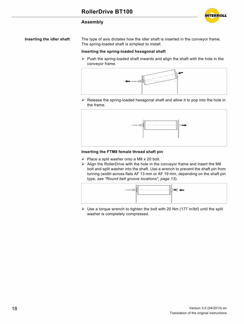
Inserting the idler shaft The type of axis dictates how the idler shaft is inserted in the conveyor frame. The spring-loaded shaft is simplest to install.
Inserting the spring-loaded hexagonal shaft
Push the spring-loaded shaft inwards and align the shaft with the hole in the conveyor frame.
Release the spring-loaded hexagonal shaft and allow it to pop into the hole in the frame.
Inserting the FTM8 female thread shaft pin
Place a split washer onto a M8 x 20 bolt. Align the RollerDrive with the hole in the conveyor frame and insert the M8
bolt and split washer into the shaft. Use a wrench to prevent the shaft pin from turning (width across flats AF 13 mm or AF 19 mm, depending on the shaft pin type, see "Round belt groove locations", page 13).
Use a torque wrench to tighten the bolt with 20 Nm (177 in/lbf) until the split washer is completely compressed.
18 Version 3.0 (04/2013) en
Translation of the original instructions
RollerDrive BT100
Assembly
Securing the RollerDrive inthe conveyor frame
There is a nut and a retaining washer on the shaft next to the tube. This inner nut has been preassembled and secured in the correct position.
Use a flat wrench AF 19 mm to prevent the inner nut from turning. Slip a second washer and a hex nut over the motor cable and screw it onto the
threaded motor shaft. Ensure that washers are fitted on both sides of theprofile.
Use a torque wrench to tighten this outer nut with 35 Nm (308 in/lbf) while ensuring that the inner nut is not rotating.
In the version with female thread and hollow screw, the tightening torque is reduced to 15Nm (132 in/lbf).
Mounting tool
For mounting the PolyVee belt, you may want to build a mounting tool as shown in the figure below.
Place the mounting tool between two rollers to reduce the gap between theadjacent rollers.
Hint
Do not adjust the inner nut and retaining washer.
Hint
An angular compensation on the motor end is needed to prevent bending forces on conical RollerDrives.
Hint
Dimensions of the mounting tool depend on the roller pitch and the roller tube diameter.
19Version 3.0 (04/2013) en
Translation of the original instructions
RollerDrive BT100
Assembly
Electrical installation
The electrical installation depends on the version of the RollerDrive BT100:• With plug• With cable
Connecting with plug Connect the motor plug to the DriveControl.
Connecting with cable Connect the pins of the motor cable to your control (for the pin definition, see "Motor cable and plug", page 10).
Hint
For the recommended DriveControls, see "DriveControl for the RollerDrive BT100", page 10.
20 Version 3.0 (04/2013) en
Translation of the original instructions
RollerDrive BT100
Initial startup and operation
Initial startup
Inspections before initialstartup
Ensure that no objects are in contact with rotating or moving parts. Ensure that all bolts are tightened according to the specifications. Ensure that no additional dangerous areas arise due to interfaces with other
components. Ensure that the wiring is in accordance with specifications and legal
guidelines. Check all protection devices. Ensure that no bystanders are in dangerous areas around the conveyor.
Operation
Inspections before everystartup
Check the RollerDrive for visible damage. Check all protection devices. Ensure that no bystanders are in dangerous areas around the conveyor. Clearly specify and monitor the way goods are placed on the conveyor. Make sure that the RollerDrive is not blocked.
Procedure in case of accident or malfunction
Stop the conveyor at once and ensure that it cannot be started accidentally. In case of an accident: Provide first aid and call for emergency assistance. Inform responsible persons. Have the malfunction repaired by qualified persons. Start the conveyor only after this has been approved by qualified persons.
Hint
For information about startup, see the manual for the DriveControl or your control.
Rotating parts and accidental start-upRisk of pinched fingers
Do not insert fingers between the RollerDrive and the round belt, PolyVee belt or roller chain.
Do not remove the protection device. Keep fingers, hair and loose clothing away from the
RollerDrive.
Damage to the motor or the control due to induction Do not push items along the roller conveyor by hand. Do not spin the RollerDrive manually.
CAUTION
Hint
Ambient conditions during operation see "Technical specifications", page 9
21Version 3.0 (04/2013) en
Translation of the original instructions
RollerDrive BT100
Maintenance and cleaning
Warnings concerning maintenance and cleaning
Maintenance
Checking the RollerDrive If the RollerDrive is not secured as specified in the installation instructions (see "Assembly", page 15), it may rotate in the hole in the conveyor frame. This causes the RollerDrive to also rotate, and it can be damaged.
Monthly check the RollerDrive for visible damage. Annually ensure that the roller shaft is secured properly in the conveyor
frame.
Replacing a RollerDrive If a RollerDrive is damaged or broken down, must be replaced.
Install a new RollerDrive (see "Abandonment", page 24 and see "RollerDrive Installation", page 17).
Cleaning
Increased surface friction reduces the roller speed since more power is used to overcome the resistance. Therefore, in a dirty environment, periodic cleaning will ensure good contact with the goods and reduce friction.
Remove foreign materials and dirt with a simple cleaning brush (not a wire brush) by brushing gently.
Remove smaller amounts of dirt with a damp cloth. When doing this, make sure that wetting of the RollerDrive is no more than slightly damp.
Do not use sharp-edged tools to clean the roller.
Risk of injury due to improper handling or accidental motor starts Maintenance work and cleaning may only be executed
by qualified and authorized persons. Only perform maintenance work after switching off the
power. Ensure that the RollerDrive cannot be turned on accidentally.
Set up signs indicating maintenance work.
CAUTION
22 Version 3.0 (04/2013) en
Translation of the original instructions
RollerDrive BT100
Troubleshooting
Troubleshooting
Risk of injuries due to incorrect handling Troubleshooting may only be done by qualified and
authorized persons. Only perform troubleshooting after switching off the
power. Ensure that the RollerDrive cannot be turned on
accidentally.
CAUTION
Symptom Possible cause Help
RollerDrive is not operating No power supply Check 24 VDC power supply.
Plugs not connected properly Check cable connection.
RollerDrive is rotating in the wrong direction.
Incorrect polarity Swap over the polarity of the connection.
Abnormal noise coming out of the RollerDrive
Motor or gearbox is damaged Replace the RollerDrive.
Interrupted RollerDrive operation Damaged motor cable Check motor cable for damage.If the motor cable is damaged, replace the RollerDrive.
23Version 3.0 (04/2013) en
Translation of the original instructions
RollerDrive BT100
Abandonment and disposal
Abandonment
Disconnect the motor cable from the control. Unscrew the outer nut at the threaded motor shaft. If the RollerDrive has a spring-loaded idler shaft, push the idler shaft inwards. If the RollerDrive has a FTM8 idler shaft, unscrew the bolt at the idler shaft. Extract the RollerDrive from the conveyor frame.
Disposal
The operator is responsible for the proper disposal of the RollerDrive. In doing so, industry-specific and local provisions must be observed for the disposal of the RollerDrive and its packaging.
Risk of injury due to improper handling Abandonment may only be executed by qualified and
authorized persons. Only abandon the RollerDrive after switching off the
power. Ensure that the RollerDrive cannot be turned on accidentally.
CAUTION
24 Version 3.0 (04/2013) en
Translation of the original instructions
RollerDrive BT100
Appendix
Accessories
Belt
DriveControl
Torque arm
Part Properties
Round belt • Belts of 4 mm (0.16 in) and max. 5 mm (0.20 in) diameter
PolyVee belt • Drive head with 9 grooves for flexible V-ribbed belts • PJ form, ISO 9981, DIN 7867 • pitch 2.34 mm (2.29 mm) • Belts with a max. of 4 ribs
Part Part #
Z-Card BT Easy 89Z1
Part Part #
Torque arm 8862
25Version 3.0 (04/2013) en
Translation of the original instructions
RollerDrive BT100
Appendix
Installation Declaration
in accordance with the EC Machinery Directive 2006/42/EC, Appendix II B
The manufacturer:
hereby declares with sole responsibility that the product range
• RollerDrive BT100
is not a ready-to-use machine as defined by the EC Machinery Directive and, therefore, does not fully comply with the requirements of this directive. Initial start-up of these conveyor modules is not permitted until conformity of the entire machine/system in which they are installed has been declared via the EC Machinery Directive.
The health and safety requirements as stated in Appendix I have been applied. The special technical documents as stated in Appendix VII B have been compiled and will be sent to the responsible authority if necessary.
Person authorized to compile the technical documents: Georg Malina, Interroll Engineering GmbH, Hoeferhof 16, D - 42929 Wermelskirchen
Applied EC directives:• Machinery Directive 98/37/EC with the amendment 98/79/EC • EMC Directive 2004/108/EC • RoHS Directive 2002/95/EC
Applied harmonized standards:• EN ISO 12100 Parts 1 and 2 "Safety of machinery - Basic concepts, general
principles for design" - Part 1: "Basic terminology, methodology" - Part 2: "Technical principles"
Wermelskirchen, 31st March 2010
Armin Lindholm
(Managing Director)
(This declaration can be obtained at www.interroll.com, if needed.)
Interroll Engineering GmbH Hoeferhof 16 D - 42929 WermelskirchenGermany
SpainInterroll España S.A. Parc Tecnològic del VallèsC/Dels Argenters, 5 Edificio 1 Bp y Cp08290 Cerdanyola del VallèsBarcelonaSpainTel + 34 90 211 [email protected]