75
USER MANUAL SecureHead™ Encrypted Magnetic Read Head USB and UART Interface 80101505-001-L 28 December 2020

USER MANUAL
SecureHead™ Encrypted Magnetic Read Head
USB and UART Interface
80101505-001-L 28 December 2020
Copyright © 2010-2020, International Technologies & Systems Corporation. All rights reserved.
Page 2 of 75
User Manual, SecureHead USB and UART Interface
Agency Approved Specifications for subpart B of part 15 of FCC rule for a Class A computing device. Limited Warranty ID TECH warrants to the original purchaser for a period of 12 months from the date of invoice that this product is in good working order and free from defects in material and workmanship under normal use and service. ID TECH’s obligation under this warranty is limited to, at its option, replacing, repairing, or giving credit for any product which has, within the warranty period, been returned to the factory of origin, transportation charges and insurance prepaid, and which is, after examination, disclosed to ID TECH’s satisfaction to be thus defective. The expense of removal and reinstallation of any item or items of equipment is not included in this warranty. No person, firm, or corporation is authorized to assume for ID TECH any other liabilities in connection with the sales of any product. In no event shall ID TECH be liable for any special, incidental or consequential damages to Purchaser or any third party caused by any defective item of equipment, whether that defect is warranted against or not. Purchaser’s sole and exclusive remedy for defective equipment, which does not conform to the requirements of sales, is to have such equipment replaced or repaired by ID TECH. For limited warranty service during the warranty period, please contact ID TECH to obtain a Return Material Authorization (RMA) number & instructions for returning the product. THIS WARRANTY IS IN LIEU OF ALL OTHER WARRANTIES OF MERCHANTABILITY OR FITNESS FOR PARTICULAR PURPOSE. THERE ARE NO OTHER WARRANTIES OR GUARANTEES, EXPRESS OR IMPLIED, OTHER THAN THOSE HEREIN STATED. THIS PRODUCT IS SOLD AS IS. IN NO EVENT SHALL ID TECH BE LIABLE FOR CLAIMS BASED UPON BREACH OF EXPRESS OR IMPLIED WARRANTY OF NEGLIGENCE OF ANY OTHER DAMAGES WHETHER DIRECT, IMMEDIATE, FORESEEABLE, CONSEQUENTIAL OR SPECIAL OR FOR ANY EXPENSE INCURRED BY REASON OF THE USE OR MISUSE, SALE OR FABRICATIONS OF PRODUCTS WHICH DO NOT CONFORM TO THE TERMS AND CONDITIONS OF THE CONTRACT.
©2010-2020 International Technologies & Systems Corporation. The information contained herein is provided to the user as a convenience. While every effort has been made to ensure accuracy, ID TECH is not responsible for damages that might occur because of errors or omissions, including any loss of profit or other commercial damage. The specifications described herein were current at the time of publication, but are subject to change at any time without prior notice.
ID TECH is a registered trademark of International Technologies & Systems Corporation. SecureHead and Value through Innovation are trademarks of International Technologies & Systems Corporation.

Copyright © 2010-2020, International Technologies & Systems Corporation. All rights reserved.
Page 3 of 75
User Manual, SecureHead USB and UART Interface
Revision History
Revision Date Description of Changes By 50 10/20/2010 Initial Draft Jenny W 51 10/25/2010 Revised read status command
Added decryption examples Jenny W
52 11/12/2010 Added UART interface cable pinout Jenny W A 05/09/2011 -Added SecureHead mounting option with drawing
to indicate track 1 location -Edited original and enhanced encryption output format -Changed device serial number length from 8 byte to 10 byte
Jenny W
B 06/21/2011 Added design guidelines for head installation Jenny W C 09/20/2011 - Updated USB interface Cable Pin Out
- Updated power information Yvonne Y
D 03/23/2012 -Added design guidelines on preloading the spring -Added cable length tolerance
Jenny W
E 02/04/2013 Added the new mask feature in SecureHead firmware v5.00 for UART interface and v 5.03 for USB interface
Candy H
F 06/05/2013 Update appendix I magnetic heads mechanical design guidelines Remove key loading command
Candy H
G 7/13/2015 Included bit to indicate status flag of service code if ICC is present. Section 4.5.4 Note 3 Example data: Appendix J
Jason H
H 8/31/2015 Remove former section 3.12 Encrypt External Data Command
Jason H
I 10/11/2016 Section 2: Update USB voltage to 7ma Jason H K 11/19/2020 Revised Appendix K CB L 12/28/2020 Removed commands related to Fixed Keys. CB

Copyright © 2010-2020, International Technologies & Systems Corporation. All rights reserved.
Page 4 of 75
User Manual, SecureHead USB and UART Interface
Table of Contents
1. INTRODUCTION........................................................................................................................ 5 2. SPECIFICATIONS ..................................................................................................................... 6 3. CONFIGURATION ................................................................................................................... 10
3.1. Setup Commands Structure ............................................................................................ 10 3.2. Communication Timing .................................................................................................. 11 3.3. Default Settings .............................................................................................................. 11 3.4. General Selections .......................................................................................................... 11 3.5. Review Settings .............................................................................................................. 12 3.6. Review Serial Number.................................................................................................... 13 3.7. Message Formatting Selections(Only for Security Level 1 & 2) ................................... 13 3.8. Magnetic Track Selections ............................................................................................. 14 3.9. Security Settings ............................................................................................................. 15 3.10. Review KSN (DUKPT Key management only) ............................................................. 16 3.11. Review Security Level.................................................................................................... 16 3.12. Encrypted Output for Decoded Data .............................................................................. 16
4. Data Format .............................................................................................................................. 21 4.1. Level 1 and level 2 Standard Mode Data Output Format ............................................... 21 4.2. Level 1 and level 2 POS Mode Data Output Format ...................................................... 27 4.3. DUKPT Key Management Level 3 Data Output Format ............................................... 30 4.4. Fixed Key Management Encrypted Output Format........................................................ 31 4.5. DUKPT Enhanced Level 3 Data Output Format ............................................................ 31 4.6. Fix Key Management Enhanced Output Data Format ................................................... 34 4.7. DUKPT Level 4 Data Output Format............................................................................. 34 4.8. Level 4 Activate Authentication Sequence..................................................................... 36 4.9. Other Command Protocol Settings ................................................................................. 40
Appendix A Setting Parameters and Values ............................................................................... 42 Appendix B Key Code Table in USB Keyboard Interface ......................................................... 47 Appendix C Default Setting Table ................................................................................................. 54 Appendix D Magnetic Stripe Standard Formats.......................................................................... 55 Appendix E Other Mode Card Data Output ................................................................................ 58 Appendix F Guide to Encrypting and Decrypting Data ............................................................. 59 Appendix G Key Management Flow Chart ............................................................................... 60 Appendix H Example of Decoded Data Decryption................................................................... 62 Appendix I Example of IDTECH Raw Data Decryption ......................................................... 69 Appendix J Example of Data with ICC Status Flag .................................................................. 71 Appendix K Installation and Use Guide for Magnetic Heads ........................................................ 72

Copyright © 2010-2020, International Technologies & Systems Corporation. All rights reserved.
Page 5 of 75
User Manual, SecureHead USB and UART Interface
1. INTRODUCTION ID TECH SecureHead reader delivers superior reading performance with the ability to encrypt sensitive card data. The data encryption process prevents card holder information from being accessed when the data is stored or in transit, so the data remains secure from end to end. The reader fully supports TDES and AES data encryption using DUKPT key management method. The SecureHead supports SPI, UART and USB interface. The information about SPI SecureHead can be found in a separate document, 80101502-001 SecureHead SPI user manual. .
Copyright © 2010-2020, International Technologies & Systems Corporation. All rights reserved.
Page 6 of 75
User Manual, SecureHead USB and UART Interface
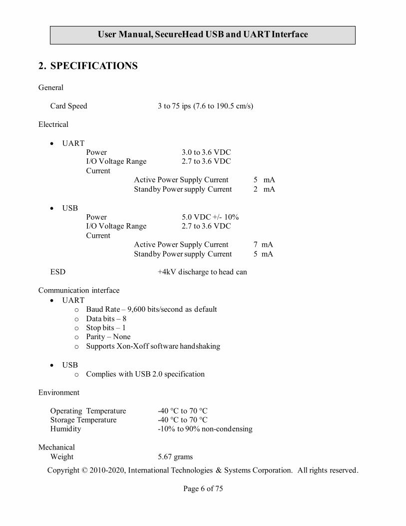
2. SPECIFICATIONS General
Card Speed 3 to 75 ips (7.6 to 190.5 cm/s)
Electrical
• UART Power 3.0 to 3.6 VDC I/O Voltage Range 2.7 to 3.6 VDC Current
Active Power Supply Current 5 mA Standby Power supply Current 2 mA
• USB
Power 5.0 VDC +/- 10% I/O Voltage Range 2.7 to 3.6 VDC Current
Active Power Supply Current 7 mA Standby Power supply Current 5 mA
ESD +4kV discharge to head can Communication interface
• UART o Baud Rate – 9,600 bits/second as default o Data bits – 8 o Stop bits – 1 o Parity – None o Supports Xon-Xoff software handshaking
• USB o Complies with USB 2.0 specification
Environment
Operating Temperature -40 °C to 70 °C Storage Temperature -40 °C to 70 °C Humidity -10% to 90% non-condensing
Mechanical
Weight 5.67 grams
Copyright © 2010-2020, International Technologies & Systems Corporation. All rights reserved.
Page 7 of 75
User Manual, SecureHead USB and UART Interface
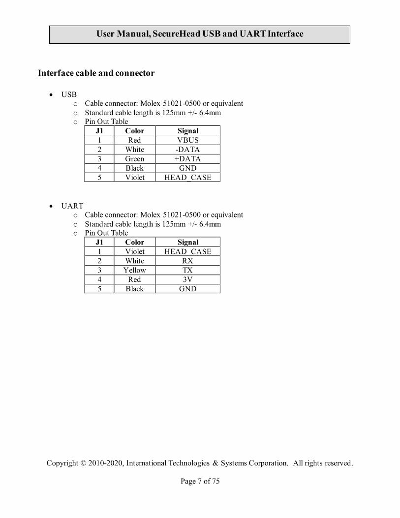
Interface cable and connector
• USB o Cable connector: Molex 51021-0500 or equivalent o Standard cable length is 125mm +/- 6.4mm o Pin Out Table
J1 Color Signal 1 Red VBUS 2 White -DATA 3 Green +DATA 4 Black GND 5 Violet HEAD_CASE
• UART o Cable connector: Molex 51021-0500 or equivalent o Standard cable length is 125mm +/- 6.4mm o Pin Out Table
J1 Color Signal 1 Violet HEAD_CASE 2 White RX 3 Yellow TX 4 Red 3V 5 Black GND
Copyright © 2010-2020, International Technologies & Systems Corporation. All rights reserved.
Page 8 of 75
User Manual, SecureHead USB and UART Interface
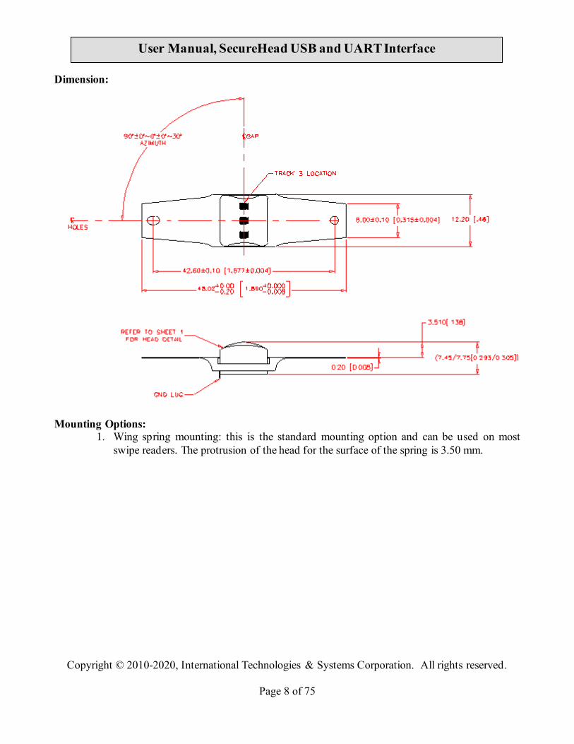
Dimension:
Mounting Options:
1. Wing spring mounting: this is the standard mounting option and can be used on most swipe readers. The protrusion of the head for the surface of the spring is 3.50 mm.

Copyright © 2010-2020, International Technologies & Systems Corporation. All rights reserved.
Page 9 of 75
User Manual, SecureHead USB and UART Interface
2. Head assembly only: This option is provided for special applications.
The mechanical interface is an eight pin male Molex Connector 51021-0800 for option 1 and 2.

Copyright © 2010-2020, International Technologies & Systems Corporation. All rights reserved.
Page 10 of 75
User Manual, SecureHead USB and UART Interface
3. CONFIGURATION The SecureHead reader must be appropriately configured to your application. Configuration settings enable the reader to work with the host system. Once programmed, these configuration settings are stored in the reader’s non-volatile memory (so they are not affected by the cycling of power).
3.1. Setup Commands Structure Commands sent to SecureHead a. Setting Command: <STX><S>[<FuncID><Len><FuncData>…]<ETX><CheckSum> b. Read Status Command: <STX><R><FuncID><ETX><CheckSum> c. Function Command: <STX>[<FuncID><Len><FuncData>…]<ETX><CheckSum> Response from SecureHead a. Setting Command Host SecureHead Setting Command <ACK> if OK or <NAK> if Error b. Read Status Command Host SecureHead Read Status Command <ACK> and <Response> if
OK
or <NAK> if Error c. Other Command Host SecureHead Other Command <ACK> and <Response> if
OK
or <NAK> if Error

Copyright © 2010-2020, International Technologies & Systems Corporation. All rights reserved.
Page 11 of 75
User Manual, SecureHead USB and UART Interface
Where: <STX> 02h <S> Indicates setting commands. 53h
<R> Indicates read status commands. 52h
<FuncID> One byte Function ID identifies the particular function or settings affected.
<Len> One byte length count for the following data block<FuncData>
<FuncData> data block for the function <ETX> 03h <CheckSum> Check Sum: The overall Modulo 2
(Exclusive OR) sum (from <STX> to <CheckSum>) should be zero.
<ACK> 06h <NAK> 15h
3.2. Communication Timing The SecureHead takes time to process a command. During that processing time, it will not respond to a new command.
The typical delay for the reader to respond to a command is 20ms, the maximum delay for the reader to respond can be as much as 40ms. Caution must therefore be taken to maintain a minimum delay between two commands.
3.3. Default Settings The SecureHead reader is shipped from the factory with the default settings already programmed. In the following sections, the default settings are shown in boldface. For a table of default settings, see Appendix A.
3.4. General Selections This group of configuration settings defines the basic operating parameters of SecureHead.
3.4.1. Change to Default Settings <STX><S><18h><ETX><CheckSum> This command does not have any <FuncData>. It returns all settings for all groups to their default values.
3.4.2. MSR Reading Settings Enable or Disable the SecureHead. If the reader is disabled, no data will be sent out to the host.
Copyright © 2010-2020, International Technologies & Systems Corporation. All rights reserved.
Page 12 of 75
User Manual, SecureHead USB and UART Interface
<STX><S><1Ah><01h><MSR Reading Settings><ETX><CheckSum> MSR Reading Settings: “0” MSR Reading Disabled “1” MSR Reading Enabled
3.4.3. Decoding Method Settings The SecureHead can support four kinds of decoded directions. <STX><S><1Dh><01h><Decoding Method Settings><ETX><CheckSum> Decoding Method Settings: “0” Raw Data Decoding in Both Directions, send out in ID TECH mode “1” Decoding in Both Directions. If the encryption feature is enabled, the key management method used is DUKPT. “2” Moving stripe along head in direction of encoding. If the encryption feature is enabled, the key management method used is DUKPT. “3” Moving stripe along head against direction of encoding. If the encryption feature is enabled, the key management method used is DUKPT. “4” Raw Data Decoding in Both Directions, send out in other mode. If the encryption feature is enabled, the key management method used is fixed key. With the bi-directional method, the user can swipe the card in either direction and still read the data encoded on the magnetic stripe. Otherwise, the card can only be swiped in one specified direction to read the card. Raw Decoding just sends the card’s magnetic data in groups of 4 bits per character. The head reads from the first byte of each track, starting from the most significant bit. The data starts to being collected when the first 1 bit is detected. No checking is done except to verify track has or does not have magnetic data.
3.5. Review Settings <STX><R><1Fh><ETX><CheckSum>
This command does not have any <FuncData>. It activates the review settings command. SecureHead sends back an <ACK> and <Response>. <Response> format: The current setting data block is a collection of many function-setting blocks <FuncSETBLOCK> as follows: <STX><FuncSETBLOCK1>…<FuncSETBLOCKn><ETX><CheckSum> Each function-setting block <FuncSETBLOCK> has the following format: <FuncID><Len><FuncData> Where: <FuncID> is one byte identifying the setting(s) for the function. <Len> is a one byte length count for the following function-setting block <FuncData>

Copyright © 2010-2020, International Technologies & Systems Corporation. All rights reserved.
Page 13 of 75
User Manual, SecureHead USB and UART Interface
<FuncData> is the current setting for this function. It has the same format as in the sending command for this function. <FuncSETBLOCK> are in the order of their Function ID<FuncID>
3.6. Review Serial Number <STX><R><4Eh><ETX><CheckSum>
This command is to get device serial number.
3.7. Message Formatting Selections(Only for Security Level 1 & 2)
3.7.1. Terminator Setting Terminator characters are used to end a string of data in some applications.
<STX><S><21h><01h><Terminator Settings><ETX><CheckSum> <Terminator Settings>: Any one character, 00h is none; default is CR (0Dh).
3.7.2. Preamble Setting Characters can be added to the beginning of a string of data. These can be special characters for identifying a specific reading station, to format a message header expected by the receiving host, or any other character string. Up to fifteen ASCII characters can be defined.
<STX><S><D2h><Len><Preamble><ETX><CheckSum> Where: <Len>= the number of bytes of preamble string <Preamble> = {string length}{string} NOTE: String length is one byte, maximum fifteen <0Fh>.
3.7.3. Postamble Setting The postamble serves the same purpose as the preamble, except it is added to the end of the data string, after any terminator characters. <STX><S><D3h><Len><Postamble><ETX><CheckSum> Where: <Len> = the number of bytes of postamble string <Postamble> = {string length}{string} NOTE: String length is one byte, maximum fifteen <0Fh>.

Copyright © 2010-2020, International Technologies & Systems Corporation. All rights reserved.
Page 14 of 75
User Manual, SecureHead USB and UART Interface
3.7.4. Track n Prefix Setting Characters can be added to the beginning of a track data. These can be special characters to identify the specific track to the receiving host, or any other character string. Up to six ASCII characters can be defined. <STX><S><n><Len><Prefix><ETX><CheckSum> Where: <n> = 34h for track 1; 35h for track 2 and 36h for track 3 <Len> = the number of bytes of prefix string <Prefix> = {string length}{string} NOTE: String length is one byte, maximum six.
3.7.5. Track n Suffix Setting Characters can be added to the end of track data. These can be special characters to identify the specific track to the receiving host, or any other character string. Up to six ASCII characters can be defined.
<STX><S><n><Len><Suffix><ETX><CheckSum> Where: <n> = 37h for track 1; 38h for track 2 and 39h for track 3 <Len> = the number of bytes of suffix string <Suffix> = {string length}{string} NOTE: String length is one byte, maximum six.
3.8. Magnetic Track Selections
3.8.1. Track Selection There are up to three tracks of encoded data on a magnetic stripe. This option selects the tracks that will be read and decoded. <STX><S><13h><01h><Track_Selection Settings><ETX><CheckSum> Track_Selection Settings: “0” Any Track “1” Require Track 1 Only “2” Require Track 2 Only “3” Require Track 1 & Track 2 “4” Require Track 3 Only “5” Require Track 1 & Track 3
Copyright © 2010-2020, International Technologies & Systems Corporation. All rights reserved.
Page 15 of 75
User Manual, SecureHead USB and UART Interface
“6” Require Track 2 & Track 3 “7” Require All Three Tracks “8” Any Track 1 & 2 “9” Any Track 2 & 3
Note: If any of the required multiple tracks fail to read for any reason, no data for any track will be sent.
3.8.2. Track Separator Selection This option allows the user to select the character to be used to separate data decoded by a multiple-track reader. <STX><S><17h><01h><Track_Separator><ETX><CheckSum> <Track_Separator> is one ASCII Character. The default value is CR, 0h means no track separator.
3.8.3. Start/End Sentinel and Track 2 Account Number Only The SecureHead can be set to either send, or not send, the Start/End sentinel, and to send either the Track 2 account number only, or all the encoded data on Track 2. (The Track 2 account number setting doesn’t affect the output of Track 1 and Track 3.) <STX><S><19h><01h><SendOption><ETX><CheckSum> SendOption: “0” Don’t send start/end sentinel and send all data on Track 2 “1” Send start/end sentinel and send all data on Track 2 “2” Don’t send start/end sentinel and send account # on Track 2 “3” Send start/end sentinel and send account number on Track 2
3.9. Security Settings
3.9.1. Encryption Settings Enable or disable the SecureHead Encryption output in ID TECH protocol. If encryption is disabled, original data will be sent out to the host. If it enabled, encrypted data will be send out to the host. <STX><S><4Ch><01h><Encryption Settings><ETX><CheckSum> Encryption Settings: “0” Encryption Disabled “1” Enable TDES Encryption
“2” Enable AES Encryption (Not for Raw Data Decoding in Both Directions, send out in other mode.)
Copyright © 2010-2020, International Technologies & Systems Corporation. All rights reserved.
Page 16 of 75
User Manual, SecureHead USB and UART Interface
3.10. Review KSN (DUKPT Key management only) <STX><R><51h><ETX><CheckSum> This command is to get DUKPT key serial number and counter.
3.11. Review Security Level <STX><R><7Eh><ETX><CheckSum>
This command is to get the current security level.
3.12. Encrypted Output for Decoded Data
3.12.1.Encrypt Functions
When a card is swiped through the Reader, the track data will be TDEA (Triple Data Encryption Algorithm, aka, Triple DES) or AES (Advanced Encryption Standard) encrypted using Fixed key management or DUKPT (Derived Unique Key Per Transaction) key management. DUKPT key management uses a base derivation key to encrypt a key serial number that produces an initial encryption key which is injected into the Reader prior to deployment. After each transaction, the encryption key is modified per the DUKPT algorithm so that each transaction uses a unique key. Thus, the data will be encrypted with a different encryption key for each transaction.
3.12.2.Security Related Function ID Security Related Function IDs are listed below. Their functions are described in other sections. Characters Hex Value Description PrePANID 49 First N Digits in PAN which can be
clear data PostPANID 4A Last M Digits in PAN which can be
clear data MaskCharID 4B Character used to mask PAN EncryptionID 4C Security Algorithm SecurityLevelID 7E Security Level (Read Only) Device Serial Number ID 4E Device Serial Number (Can be write
once. After that, can only be read) DisplayExpirationDataID 50 Display expiration data as mask
data or clear data KSN and Counter ID 51 Review the Key Serial Number and

Copyright © 2010-2020, International Technologies & Systems Corporation. All rights reserved.
Page 17 of 75
User Manual, SecureHead USB and UART Interface
Encryption Counter Session ID 54 Set current Session ID Key Management Type ID
58 Select Key Management Type
Feasible settings of these new functions are listed below. Characters Default Setting Description PrePANID 04h 00h ~ 06h
Allowed clear text from start of PAN Command format: 02 53 49 01 04 03 LRC
PostPANID 04h 00h ~ 04h Allowed clear text from end of PAN Command format: 02 53 4A 01 04 03 LRC
MaskCharID ‘*’ 20h ~ 7Eh Command format: 02 53 4B 01 3A 03 LRC
DisplayExpirationDataID ‘0’ ‘0’ Display expiration data as mask data ‘1’ Display expiration data as clear data
EncryptionID ‘0’ ‘0’ Clear Text ‘1’ Triple DES ‘2’ AES Command format: 02 53 4C 01 31 03 LRC
SecurityLevelID ‘1’ ‘0’ ~ ‘3’ Command format: 02 52 7E 03 LRC
Device Serial Number ID 00, 00, 00, 00, 00, 00, 00, 00, 00, 00
10 bytes number: Command format: Set Serial Number: 02 53 01 4E 09 08 37 36 35 34 33 32 31 30 03 LRC Get Serial Number: 02 52 4E 03 LRC
KSN and Counter ID 00, 00, 00, 00, 00, 00, 00, 00, 00, 00
This field includes the Initial Key Serial Number in the leftmost 59 bits and a value for the Encryption Counter in the right most 21 bits. Get DUKPT KSN and Counter: 02 52 51 03 LRC

Copyright © 2010-2020, International Technologies & Systems Corporation. All rights reserved.
Page 18 of 75
User Manual, SecureHead USB and UART Interface
Session ID 00, 00, 00, 00, 00, 00, 00, 00
This Session ID is an eight bytes string which contains any hex data. This filed is used by the host to uniquely identify the present transaction. Its primary purpose is to prevent replays. It is only be used at Security Level 4. After a card is read, the Session ID will be encrypted, along with the card data, a supplied as part of the transaction message. The clear text version of this will never be transmitted. New Session ID stays in effect until one of the following ocurrs: 1. Another Set Session ID command is received. 2. The reader is powered down. 3. The reader is put into Suspend mode.
Key Management Type ID
‘1’ Fixed key management by default. ‘0’: Fixed Key ‘1’: DUKPT Key
3.12.3.Security Management
This reader is intended to be a secure reader. Security features include: • Can include Device Serial Number • Can encrypt track 1 and track 2 data for all bank cards • Provides clear text confirmation data including card holder’s name and a portion of
the PAN as part of the Masked Track Data • Optional display expiration data • Security Level is settable
The reader features configurable security settings. Before encryption can be enabled, Key Serial Number (KSN) and Base Derivation Key (BDK) must be loaded before encrypted transactions can take place. The keys are to be injected by certified key injection facility.
There are five security levels available when using the DUKPT key management:
• Level 0
Security Level 0 is a special case where all DUKPT keys have been used and is set automatically when it runs out of DUKPT keys. The lifetime of DUKPT keys is 1 million. Once the key’s end of life time is reached, user should inject DUKPT keys again before doing any more transactions.
Copyright © 2010-2020, International Technologies & Systems Corporation. All rights reserved.
Page 19 of 75
User Manual, SecureHead USB and UART Interface
• Level 1
By default, readers from the factory are configured to have this security level. There is no encryption process, no key serial number transmitted with decoded data. The reader functions as a non-encrypting reader and the decoded track data is sent out in default mode.
• Level 2
Key Serial Number and Base Derivation Key have been injected but the encryption process is not yet activated. The reader will send out decoded track data in default format. Setting the encryption type to TDES and AES will change the reader to security level 3.
• Level 3 Both Key Serial Number and Base Derivation Keys are injected and encryption mode is turned on. For payment cards, both encrypted data and masked clear text data are sent out. Users can select the data masking of the PAN area; the encrypted data format cannot be modified. Users can choose whether to send hashed data and whether to reveal the card expiration date. When the encryption is turned on, level 3 is the default security level.
• Level 4 When the reader is at Security Level 4, a correctly executed Authentication Sequence is required before the reader sends out data for each card swipe.
3.12.4.Encryption Management
The Encrypted swipe read supports TDES and AES encryption standards for data encryption. Encryption can be turned on via a command. TDES is the default. If the reader is in security level 3, for the encrypted fields, the original data is encrypted using the TDES/AES CBC mode with an Initialization Vector starting at all binary zeroes and the Encryption Key associated with the current DUKPT KSN.
3.12.5.Check Card Format
• ISO/ABA (American Banking Association) Card Encoding method Track1 is 7 bits encoding.
Track1 is 7 bits encoding. Track2 is 5 bits encoding. Track3 is 5 bits encoding. Track1 is 7 bits encoding. Track2 is 5 bits encoding. Track2 is 5 bits encoding.
Additional check
Copyright © 2010-2020, International Technologies & Systems Corporation. All rights reserved.
Page 20 of 75
User Manual, SecureHead USB and UART Interface
Track1 2nd byte is ‘B’. There is only one ‘=’ in track 2 and the position of ‘=’ is between 12th ~ 20th character. Total length of track 2 should above 21 characters.
• AAMVA (American Association of Motor Vehicle Administration) Card
Encoding method Track1 is 7 bits encoding. Track2 is 5 bits encoding. Track3 is 7 bits encoding.
• Others (Customer card)
3.12.6.MSR Data Masking
For cards need to be encrypted, both encrypted data and clear text data are sent. Masked Area
The data format of each masked track is ASCII. The clear data include start and end sentinels, separators, first N, last M digits of the PAN, card holder name (for Track1). The rest of the characters should be masked using mask character.
Set PrePANClrData (N), PostPANClrData (M), MaskChar (Mask Character)
N and M are configurable and default to 4 first and 4 last digits. They follow the current PCI constraints requirements (N 6, M 4 maximum). Mask character default value is ‘*’.
• Set PrePANClrDataID (N), parameter range 00h ~ 06h, default value 04h
• Set PostPANClrDataID (M), parameter range 00h ~ 04h, default value 04h
• MaskCharID (Mask Character), parameter range 20h ~ 7Eh, default value 2Ah
• DisplayExpirationDataID, parameter range ‘0’~’1’, default value ‘0’
Copyright © 2010-2020, International Technologies & Systems Corporation. All rights reserved.
Page 21 of 75
User Manual, SecureHead USB and UART Interface
4. Data Format The USB version of the reader can be operated in two different modes: - HID ID TECH mode (herein referred to as “HID mode”) - HID with Keyboard Emulation (herein referred to as “KB mode”).
When the reader is operated in the HID mode, it behaves like a vendor defined HID device. A direct communication path can be established between the host application and the reader without interference from other HID devices.
4.1. Level 1 and level 2 Standard Mode Data Output Format
Magnetic Track Basic Decoded Data Format Track 1: <SS1><T1 Data><ES><Track Separator> Track 2: <SS2><T2 Data><ES><Track Separator> Track 3: <SS3><T3 Data><ES><Terminator> Where: SS1 (start sentinel track 1) = % SS2 (start sentinel track 2) = ; SS3 (start sentinel track 3) = ; for ISO, % for AAMVA ES (end sentinel all tracks) = ? Track Separator = Carriage Return
Terminator = Carriage Return Language: US English
Magnetic Track Basic Raw Data Format Track 1: <01><T1 Raw Data><CR> Track 2: <01><T2 Raw Data><CR> Track 3: <T3 Raw Data><CR> Where: The length of T1 Raw Data, T2 Raw Data, T3 Raw Data is 0x60 for each field. Pad with 0 if the original data length doesn’t reach 0x60.
Language: US English Definitions

Copyright © 2010-2020, International Technologies & Systems Corporation. All rights reserved.
Page 22 of 75
User Manual, SecureHead USB and UART Interface
Start or End Sentinel: Characters in encoding format which come before the first data character (start) and after the last data character (end), indicating the beginning and end, respectively, of data. Track Separator: A designated character which separates data tracks. Terminator: A designated character which comes at the end of the last track of data, to separate card reads.
Card data is only sent to the host on the Interrupt In pipe using an Input Report. The reader will send only one Input Report per card swipe. If the host requests data from the reader when no data is available, the reader will send a NAK to the host to indicate that it has nothing to send.
Data Format Setting: – USB HID Data Format (default setting), Product ID: 2010 - USB Keyboard Format, Product ID: 2030 When the reader is plugged in, the firmware will read the "Data Format Setting" from non-volatile memory and send current Product ID in enumeration. After the setting is changed, the firmware will save the setting then do enumeration process.

Copyright © 2010-2020, International Technologies & Systems Corporation. All rights reserved.
Page 23 of 75
User Manual, SecureHead USB and UART Interface
4.1.1. USB HID Data Format ID TECH HID Reader Data Structure Offset Usage Name . 0 T1 decode status 1 T2 decode status 2 T3 decode status 3 T1 data length 4 T2 data length 5 T3 data length 6 Card encode type 7, 8 Total Output Length 9-512 Output Data In this approach, the reader will keep all of the ID TECH data editing and other features like preamble, postamble, etc. The output data is always 512 bytes; the "Total Output Length" field indicates the valid data length in the output data
4.1.2. Descriptor Tables
Device Descriptor:
Field Value Description Length 12 Des type 01 bcd USB 00 02 USB 2.0 Device Class 00 Unused Sub Class 00 Unused Device Protocol 00 Unused Max Packet Size 08 VID 0A CD PID 20 10
20 20 20 30
HID ID TECH Structure HID Other Structure HID Keyboard
BCD Device Release 00 01 i-Manufacture 01 i-Product 02 i-Serial-Number 00 # Configuration 01

Copyright © 2010-2020, International Technologies & Systems Corporation. All rights reserved.
Page 24 of 75
User Manual, SecureHead USB and UART Interface
Configuration Descriptor:
Field Value Description Length 09 Des type 02 Total Length 22 00 No. Interface 01 Configuration Value 01 iConfiguration 00 Attributes 80 Bus power, no remove wakeup Power 32 100 mA
Interface Descriptor:
Field Value Description Length 09 Des type 04 Interface No. 00 Alternator Setting 00 # EP 01 Interface Class 03 HID Sub Class 01 Interface Protocol 01 iInterface 00
HID Descriptor:
Field Value Description Length 09 Des type 21 HID bcdHID 11 01 Control Code 00 numDescriptors 01 Number of Class Descriptors to follow DescriptorType 22 Report Descriptor Descriptor Length 37 00
3D 00 52 00
HID ID TECH format HID Other format HID Keyboard format
End Pointer Descriptor: Field Value Description
Copyright © 2010-2020, International Technologies & Systems Corporation. All rights reserved.
Page 25 of 75
User Manual, SecureHead USB and UART Interface
Length 07 Des Type 05 End Point EP Addr 83 EP3 – In Attributes 03 Interrupt MaxPacketSize 40 00 bInterval 01
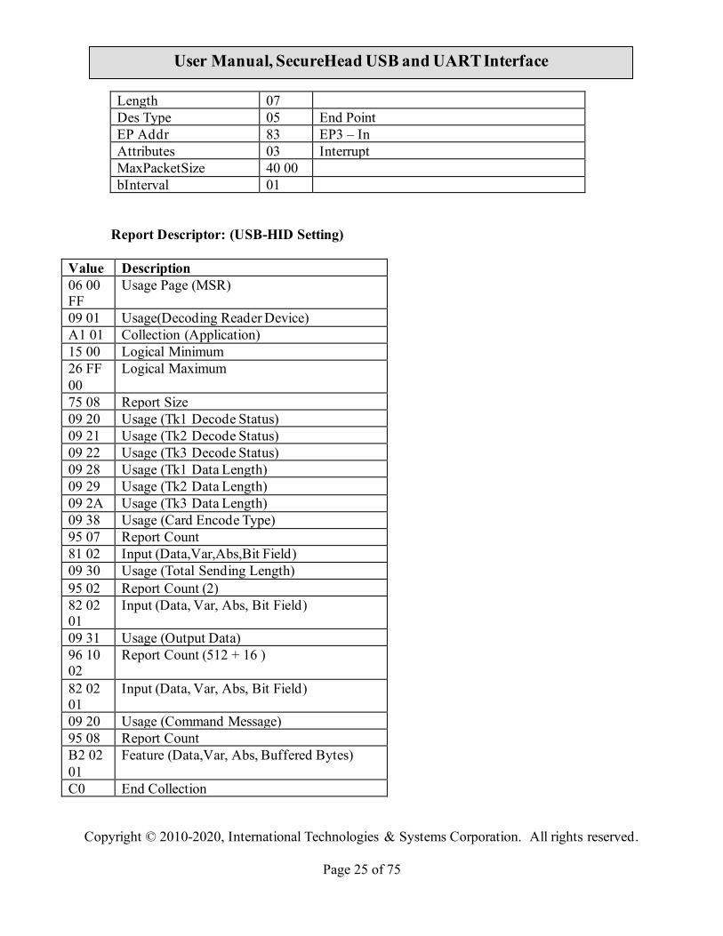
Report Descriptor: (USB-HID Setting)
Value Description 06 00 FF
Usage Page (MSR)
09 01 Usage(Decoding Reader Device) A1 01 Collection (Application) 15 00 Logical Minimum 26 FF 00
Logical Maximum
75 08 Report Size 09 20 Usage (Tk1 Decode Status) 09 21 Usage (Tk2 Decode Status) 09 22 Usage (Tk3 Decode Status) 09 28 Usage (Tk1 Data Length) 09 29 Usage (Tk2 Data Length) 09 2A Usage (Tk3 Data Length) 09 38 Usage (Card Encode Type) 95 07 Report Count 81 02 Input (Data,Var,Abs,Bit Field) 09 30 Usage (Total Sending Length) 95 02 Report Count (2) 82 02 01
Input (Data, Var, Abs, Bit Field)
09 31 Usage (Output Data) 96 10 02
Report Count (512 + 16 )
82 02 01
Input (Data, Var, Abs, Bit Field)
09 20 Usage (Command Message) 95 08 Report Count B2 02 01
Feature (Data,Var, Abs, Buffered Bytes)
C0 End Collection

Copyright © 2010-2020, International Technologies & Systems Corporation. All rights reserved.
Page 26 of 75
User Manual, SecureHead USB and UART Interface
Report Descriptor: (USB KB Interface) Value Description 05 01 Usage Page (Generic Desktop) 09 06 Usage(Keyboard) A1 01 Collection (Application) 05 07 Usage Page (Key Codes) 19 E0 Usage Minimum 29 E7 Usage Maximum 15 00 Logical Minimum 25 01 Logical Maximum 75 01 Report Size 95 08 Report Count 81 02 Input (Data,Variable,Absolute) 95 01 Report Count (1) 75 08 Report Size 81 01 Input Constant 95 05 Report Count 75 01 Report Size 05 08 Usage Page (LED) 19 01 Usage Minimum 29 05 Usage maximum 91 02 Output(Data Variable Absolute) 95 01 Report Count 75 03 Report Size 91 01 Output (Constant) 95 06 Report Count 75 08 Report Size 15 00 Logical Minimum 25 66 Logical Maximum (102) 05 07 Usage Page (key Code) 19 00 Usage Minimum 29 66 Usage Maximum (102) 81 00 Input(Data, Array) 06 2D FF
Usage Page (ID TECH)
95 01 Report Count 26 FF 00
Logical maximum (255)
15 01 Logical Minimum 75 08 Report Size (8) 09 20 Usage (Setup data byte) 95 08 Report Count (8)

Copyright © 2010-2020, International Technologies & Systems Corporation. All rights reserved.
Page 27 of 75
User Manual, SecureHead USB and UART Interface
B2 02 01
Feature (Data Var, Abs)
C0 End Collection
4.2. Level 1 and level 2 POS Mode Data Output Format
In POS mode use the special envelope to send out card data, envelope is in the following format:
[Right Shift, Left Shift, Right Ctrl, Left Ctrl,] Read Error, Track x ID; Track x Error; Track x Data Length; Track x Data; Card Track x LEC code; Track x data LRC.
Reader will send out card data in Alt mode if its ASCII code less than H’20’.
Byte NO. Name 0 Right Shift 1 Left Shift 2 Right Ctrl 3 Left Ctrl 4 Read Error 1 5 Read Error 2 6 Track x ID 7 Track x Error 8 Track x Length 1 9 Track x Length 2 10 Track Data (no extra
Track ID for raw data) … 10 + Track len -1 Card Track x LRC 10 + Track len Track x LRC 10 + Track len +1 0x0D 10 + Track len + 2 Track x ID …. Repeat Track
The data format is independent with MSR setting. No Track x data if track x sampling data
does not exist.
OPOS header: Only HID KB interface has [Right Shift, Left Shift, Right Ctrl, Left Ctrl] under POS mode.
Read Error: Read Error 1 byte bits: MB LB

Copyright © 2010-2020, International Technologies & Systems Corporation. All rights reserved.
Page 28 of 75
User Manual, SecureHead USB and UART Interface
0 B6 B5 B4 B3 B2 B1 B0 B0 1: Track 1 sampling data exists (0: Track 1 sampling data does not exist) B1 1: Track 2 sampling data exists (0: Track 2 sampling data does not exist) B2 1: Track 3 sampling data exists (0: Track 3 sampling data does not exist) B3 1: Track 1 decode success (0: Track 1 decode fail) B4 1: Track 2 decode success (0: Track 2 decode fail) B5 1: Track 3 decode success (0: Track 3 decode fail) B6 0: if b0 to b5 are all 1, otherwise 1 (make it printable)
Read Error byte 2:
MB LB 0 1 B12 B11 B10 B9 B8 B7
B7 1: Track 4 sampling data exists (0: Track 4 sampling data does not exist) B8 1: Track 4 JIS II decode success (0: Track4 JIS II decode fail) B9, B10, B11
000: ISO Card (7, 5) or (7, 5, 5) encoding 001: Old CADL Card (6, 5, 6) encoding (no longer included) 010: AAMVA Card (7, 5, 7) encoding 011: JIS I Card (8, 5, 8) encoding 100: JIS II card (8) or ISO+JIS II 110: OPOS Raw Data Output 111: JIS I + JIS II B12 Reserved for future use
Decode flag will set to 1 (B3, B4 and B5 all set to 1) in OPOS raw data mode.
Track ID Track ID is a byte of ID, it will be '1', '2' and '3' for track 1, 2 and 3; it is not accurate to use
start sentinel to identify track.
Track x Error Track x error is a byte of flags, it will be in format of: 0 0 1 b4, b3, b2 b1 b0 b0 1: Start sentinel error (0: Not start sentinel error) b1 1: End sentinel error (0: Not end sentinel error) b2 1: Parity error (0: Not parity error) b3 1: LRC error (0: Not LRC error) b4 1: Other error (0: Not other error) Track x Error is set to 0x20 in OPOS raw data mode.
Track Length
Assume actual "Track x Data Length" is hex code xy; the Track x data length for OPOS mode output will be hex code 3x, 3y.
Track x data length does not include the byte of "Track x data LRC", it is <30> <30> in case of read error on track x.

Copyright © 2010-2020, International Technologies & Systems Corporation. All rights reserved.
Page 29 of 75
User Manual, SecureHead USB and UART Interface
Track Data “Card Track x LRC code” is track x card data.
Track x LRC “Track x data LRC” is a LRC to check track x data communication; XOR all characters start
from "Track x ID" to “Track x data LRC” should be 0.

Copyright © 2010-2020, International Technologies & Systems Corporation. All rights reserved.
Page 30 of 75
User Manual, SecureHead USB and UART Interface
4.3. DUKPT Key Management Level 3 Data Output Format
For ISO card, both clear and encrypted data are sent. For other card, only clear data are sent. A card swipe returns the following data:
Card data is sent out in format of <STX><LenL><LenH><Card Data><CheckLRC><CheckSum><ETX> <STX> = 02h, <ETX> = 03h <LenL><LenH> is a two byte length of <Card Data>. <CheckLRC> is a one byte Exclusive-OR sum calculated for all <Card Data>. <CheckSum> is a one byte Sum value calculated for all <Card data>. <Card Data> card data format is shown below. ISO/ABA Data Output Format: card encoding type (0: ISO/ABA, 4: for Raw Mode) track status (bit 0,1,2:T1,2,3 decode, bit 3,4,5:T1,2,3
sampling) track 1 unencrypted length (1 byte, 0 for no track1 data) track 2 unencrypted length (1 byte, 0 for no track2 data) track 3 unencrypted length (1 byte, 0 for no track3 data) track 1 masked (Omitted if in Raw mode) track 2 masked (Omitted if in Raw mode) track 3 data (Omitted if in Raw mode) track 1 encrypted (AES/TDES encrypted data) track 2 encrypted (AES/TDES encrypted data) track 3 encrypted (Only used in Raw mode) track 1 hashed (20 bytes SHA1-Xor) track 2 hashed (20 bytes SHA1-Xor) DUKPT serial number (10 bytes)
Non ISO/ABA Data Output Format card encoding type (1: AAMVA, 3: Others) track status (bit 0,1,2:T1,2,3 decode, bit 3,4,5:T1,2,3
sampling) track 1 length (1 byte, 0 for no track1 data) track 2 length (1 byte, 0 for no track2 data) track 3 length (1 byte, 0 for no track3 data) track 1 data track 2 data track 3 data
Copyright © 2010-2020, International Technologies & Systems Corporation. All rights reserved.
Page 31 of 75
User Manual, SecureHead USB and UART Interface
4.4. Fixed Key Management Encrypted Output Format Same as 4.3 DUKPT Key Management Level 3 Data Output Format, only change <DUKPT serial number> to <device serial number> plus two NULL bytes.
4.5. DUKPT Enhanced Level 3 Data Output Format This mode is used when all tracks must be encrypted, or encrypted OPOS support is required, or when the tracks must be encrypted separately or when cards other than type 0 (ABA bank cards) must be encrypted or when track 3 must be encrypted. This format is the standard encryption format, but not yet the default encryption format.
1. Encryption Output Format Setting:
Command: 53 85 01 <Encryption Format> Encryption Format: ‘0’: Original Encryption Format ‘1’: Enhanced Encryption Format
2. Encryption Option Setting: (for enhanced encryption format only) Command: 53 84 01 <Encryption Option> Encryption Option: (default 08h) bit0: 1 – track 1 force encrypt bit1: 1 – track 2 force encrypt bit2: 1 – track 3 force encrypt bit3: 1 – track 3 force encrypt when card type is 0 bit4: 1 – new mask feature: see note 4) below
Note:
1)When force encrypt is set, this track will always be encrypted, regardless of card type. No clear/mask text will be sent. 2) If and only if in enhanced encryption format, each track is encrypted separately. Encrypted data length will round up to 8 or 16 bytes. 3) When force encrypt is not set, the data will be encrypted in original encryption format, that is, only track 1 and track 2 of type 0 cards (ABA bank cards) will be encrypted.
4) When new mask feature (bit 4) is set a) Mask data can be sent even if set to “force encrypt” (bit0-3 is set);
b) If bank card and track 3 is ISO-4909 with PAN format, T3 will be encrypted and has mask data.
Typical settings:

Copyright © 2010-2020, International Technologies & Systems Corporation. All rights reserved.
Page 32 of 75
User Manual, SecureHead USB and UART Interface
1) 08 (default): Bank card: All three tracks will be encrypted. Only T1 and T2 can have mask. Non-bank card: Will be sent in clear text.
2) 07 Force encryption. All three tracks will be encrypted without mask, regardless of card type.
3) 10 Bank card: T1 and T2 will be encrypted. If the T3 is with ISO-4909 format, it’ll be encrypted and its mask data will be sent out. Otherwise, T3 will be sent in clear text. Non-bank card: Will be sent in clear text.
4) 17 Bank card: All three tracks will be encrypted. T3 will allow to send mask if it’s in iso-4909 format Non-Bank card: Will be encrypted without mask.
3. Hash Option Setting:
Command: 53 5C 01 <Hash Option> Hash Option: (‘0’ – ‘7’) Bit0: 1 – track1 hash will be sent if data is encrypted Bit1: 1 – track2 hash will be sent if data is encrypted Bit2: 1 – track3 hash will be sent if data is encrypted
4. Mask Option Setting: (for enhanced encryption format only) Command: 53 86 01 <Mask Option> Mask Option: (Default: 0x07) bit0: 1 – tk1 mask data allow to send when encrypted bit1: 1 – tk2 mask data allow to send when encrypted bit2: 1 – tk3 mask data allow to send when encrypted When mask option bit is set – if data is encrypted (but not forced encrypted), the mask data will be sent; If mask option is not set, the mask data will not be sent under the same condition.
Card data is sent out in the following format <STX><LenL><LenH><Card Data><CheckLRC><CheckSum><ETX>
0 STX
1 Data Length low byte 2 Data Length high byte 3 Card Encode Type1
4 Track 1-3 Status2 5 Track 1 data length
Copyright © 2010-2020, International Technologies & Systems Corporation. All rights reserved.
Page 33 of 75
User Manual, SecureHead USB and UART Interface
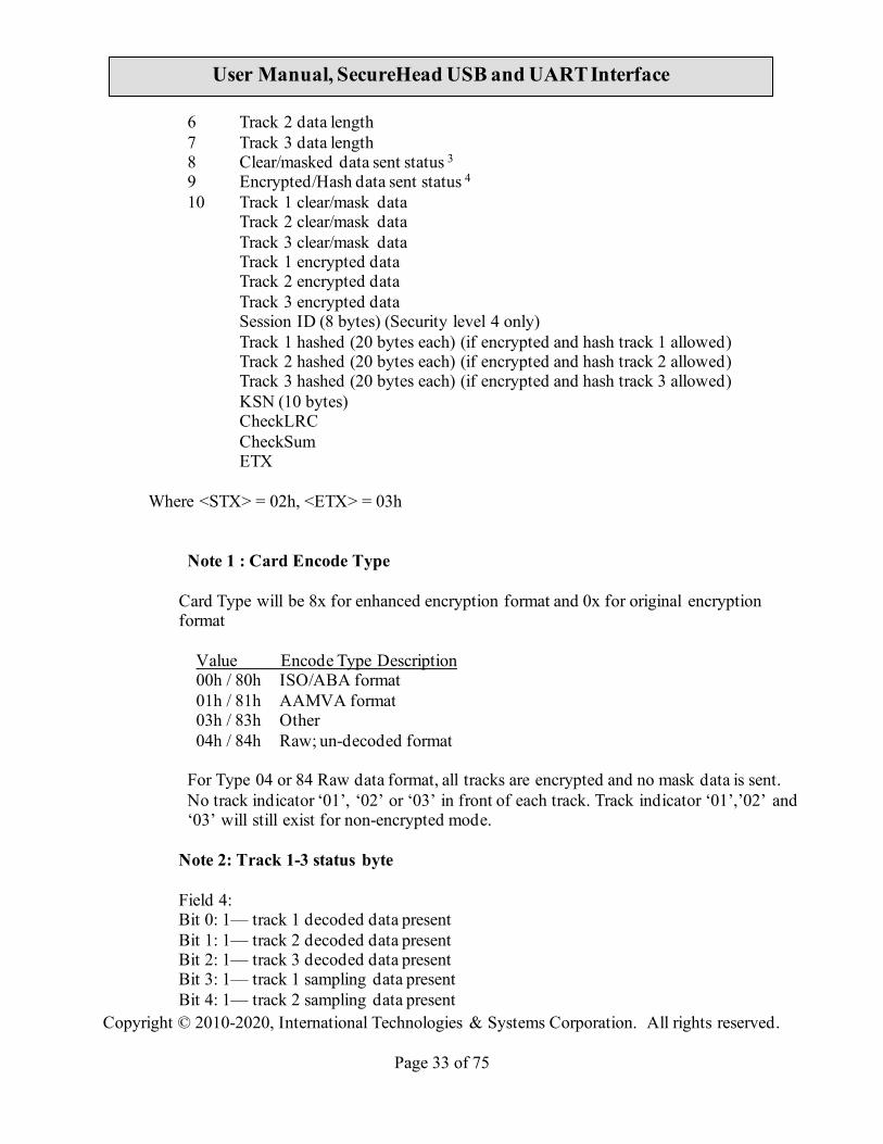
6 Track 2 data length 7 Track 3 data length 8 Clear/masked data sent status 3 9 Encrypted/Hash data sent status 4
10 Track 1 clear/mask data Track 2 clear/mask data Track 3 clear/mask data Track 1 encrypted data Track 2 encrypted data Track 3 encrypted data Session ID (8 bytes) (Security level 4 only) Track 1 hashed (20 bytes each) (if encrypted and hash track 1 allowed) Track 2 hashed (20 bytes each) (if encrypted and hash track 2 allowed) Track 3 hashed (20 bytes each) (if encrypted and hash track 3 allowed) KSN (10 bytes) CheckLRC
CheckSum ETX
Where <STX> = 02h, <ETX> = 03h
Note 1 : Card Encode Type Card Type will be 8x for enhanced encryption format and 0x for original encryption format
Value Encode Type Description 00h / 80h ISO/ABA format 01h / 81h AAMVA format 03h / 83h Other 04h / 84h Raw; un-decoded format
For Type 04 or 84 Raw data format, all tracks are encrypted and no mask data is sent. No track indicator ‘01’, ‘02’ or ‘03’ in front of each track. Track indicator ‘01’,’02’ and ‘03’ will still exist for non-encrypted mode.
Note 2: Track 1-3 status byte Field 4: Bit 0: 1— track 1 decoded data present Bit 1: 1— track 2 decoded data present Bit 2: 1— track 3 decoded data present Bit 3: 1— track 1 sampling data present Bit 4: 1— track 2 sampling data present

Copyright © 2010-2020, International Technologies & Systems Corporation. All rights reserved.
Page 34 of 75
User Manual, SecureHead USB and UART Interface
Bit 5: 1— track 3 sampling data present Bit 6, 7 — Reserved for future use
Note 3: Clear/mask data sent status
Field 8 (Clear/mask data sent status) and field 9 (Encrypted/Hash data sent status) will only be sent out in enhanced encryption format.
Field 8: Clear/masked data sent status byte: Bit 0: 1 —track 1 clear/mask data present Bit 1: 1— track 2 clear/mask data present Bit 2: 1— track 3 clear/mask data present
Bit 3: 0— reserved for future use Bit 4: 0— reserved for future use Bit 5: 0- No requirement to use IC (1st digit in Service Code is different from 2 or 6;
1-Use IC where feasible (1st digit in Service Code is 2 or 6)
Note 4: Encrypted/Hash data sent status
Field 9: Encrypted data sent status Bit 0: 1— track 1 encrypted data present Bit 1: 1— track 2 encrypted data present Bit 2: 1— track 3 encrypted data present Bit 3: 1— track 1 hash data present Bit 4: 1— track 2 hash data present Bit 5: 1— track 3 hash data present Bit 6: 1—session ID present Bit 7: 1—KSN present
4.6. Fix Key Management Enhanced Output Data Format Same as 4.5 DUKPT Enhanced Level 3 Data Output Format, only change <KSN> to <device serial number> plus two NULL bytes.
4.7. DUKPT Level 4 Data Output Format
For ISO card, both clear and encrypted data are sent. For other card, only clear data are sent. A card swipe returns the following data:
Card data is sent out in format of <STX><LenL><LenH><Card Data><CheckLRC><CheckSum><ETX>

Copyright © 2010-2020, International Technologies & Systems Corporation. All rights reserved.
Page 35 of 75
User Manual, SecureHead USB and UART Interface
<STX> = 02h, <ETX> = 03h <LenL><LenH> is a two byte length of <Card Data>. <CheckLRC> is a one byte Exclusive-OR sum calculated for all <Card Data>. <CheckSum> is a one byte Sum value calculated for all <Card data>. <Card Data> card data format is shown below. ISO/ABA Data Output Format card encoding type (0: ISO/ABA, 4: for Raw Mode) track status (bit 0,1,2:T1,2,3 decode, bit 3,4,5:T1,2,3
sampling) track 1 unencrypted length (1 byte, 0 for no track1 data) track 2 unencrypted length (1 byte, 0 for no track2 data) track 3 unencrypted length (1 byte, 0 for no track3 data) track 1 masked (Omitted if in Raw mode) track 2 masked (Omitted if in Raw mode) track 3 data (Omitted if in Raw mode) track 1 encrypted (AES/TDES encrypted data) track 2 encrypted (AES/TDES encrypted data) track 3 encrypted (Only used in Raw mode) sessionID encrypted (AES/TDES encrypted data) track 1 hashed (20 bytes SHA1-Xor) track 2 hashed (20 bytes SHA1-Xor) DUKPT serial number (10 bytes)
Non ISO/ABA Data Output Format: card encoding type (1: AAMVA, 3: Others) track status (bit 0,1,2:T1,2,3 decode, bit 3,4,5:T1,2,3
sampling) track 1 length (1 byte, 0 for no track1 data) track 2 length (1 byte, 0 for no track2 data) track 3 length (1 byte, 0 for no track3 data) track 1 data track 2 data track 3 data
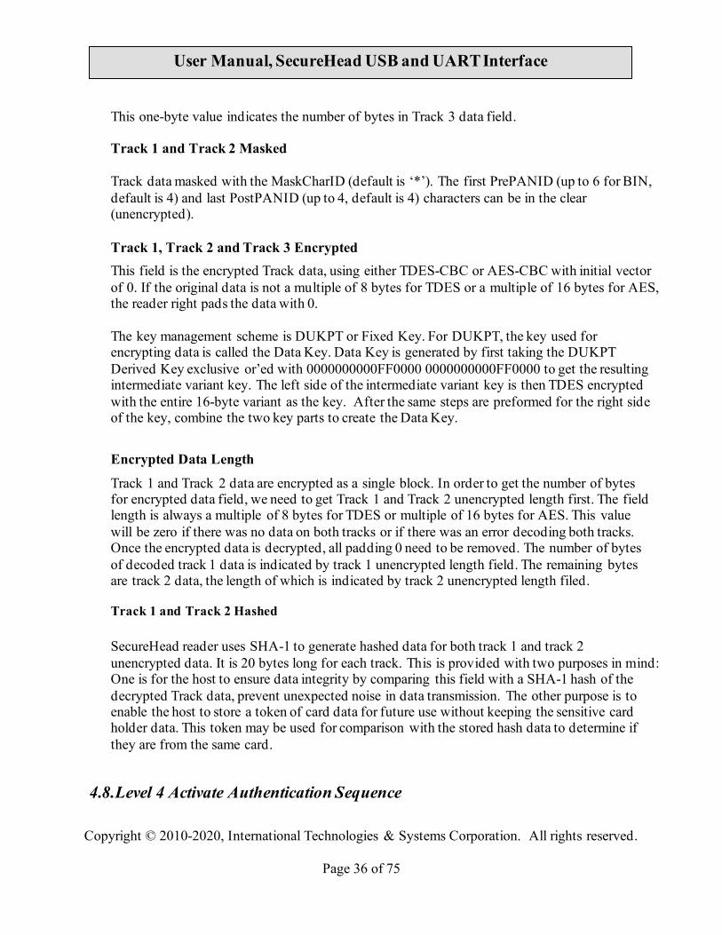
Description: Track 1, Track 2 and Track 3 Unencrypted Length This one-byte value is the length of the original Track data. It indicates the number of bytes in the Track masked data field. It should be used to separate Track 1, Track 2 and Track 3data after decrypting Track encrypted data field. Track 3 Unencrypted Length
Copyright © 2010-2020, International Technologies & Systems Corporation. All rights reserved.
Page 36 of 75
User Manual, SecureHead USB and UART Interface
This one-byte value indicates the number of bytes in Track 3 data field. Track 1 and Track 2 Masked Track data masked with the MaskCharID (default is ‘*’). The first PrePANID (up to 6 for BIN, default is 4) and last PostPANID (up to 4, default is 4) characters can be in the clear (unencrypted). Track 1, Track 2 and Track 3 Encrypted This field is the encrypted Track data, using either TDES-CBC or AES-CBC with initial vector of 0. If the original data is not a multiple of 8 bytes for TDES or a multiple of 16 bytes for AES, the reader right pads the data with 0. The key management scheme is DUKPT or Fixed Key. For DUKPT, the key used for encrypting data is called the Data Key. Data Key is generated by first taking the DUKPT Derived Key exclusive or’ed with 0000000000FF0000 0000000000FF0000 to get the resulting intermediate variant key. The left side of the intermediate variant key is then TDES encrypted with the entire 16-byte variant as the key. After the same steps are preformed for the right side of the key, combine the two key parts to create the Data Key.
Encrypted Data Length
Track 1 and Track 2 data are encrypted as a single block. In order to get the number of bytes for encrypted data field, we need to get Track 1 and Track 2 unencrypted length first. The field length is always a multiple of 8 bytes for TDES or multiple of 16 bytes for AES. This value will be zero if there was no data on both tracks or if there was an error decoding both tracks. Once the encrypted data is decrypted, all padding 0 need to be removed. The number of bytes of decoded track 1 data is indicated by track 1 unencrypted length field. The remaining bytes are track 2 data, the length of which is indicated by track 2 unencrypted length filed.
Track 1 and Track 2 Hashed
SecureHead reader uses SHA-1 to generate hashed data for both track 1 and track 2 unencrypted data. It is 20 bytes long for each track. This is provided with two purposes in mind: One is for the host to ensure data integrity by comparing this field with a SHA-1 hash of the decrypted Track data, prevent unexpected noise in data transmission. The other purpose is to enable the host to store a token of card data for future use without keeping the sensitive card holder data. This token may be used for comparison with the stored hash data to determine if they are from the same card.
4.8. Level 4 Activate Authentication Sequence
Copyright © 2010-2020, International Technologies & Systems Corporation. All rights reserved.
Page 37 of 75
User Manual, SecureHead USB and UART Interface
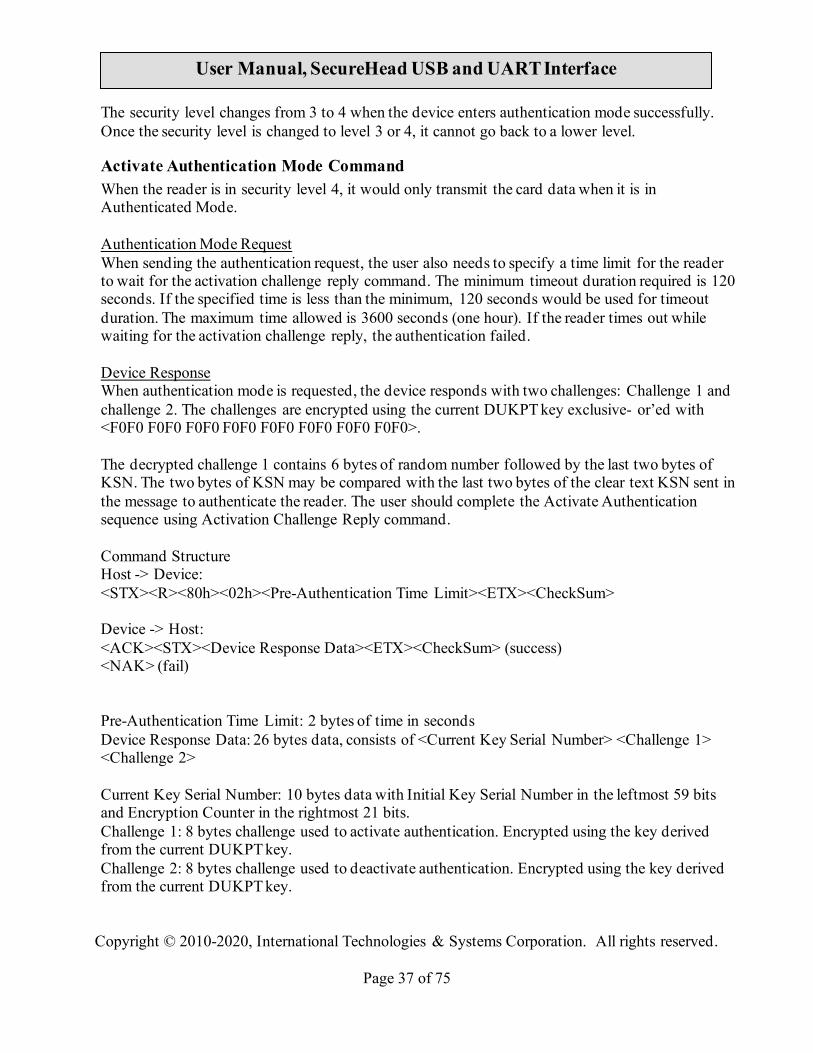
The security level changes from 3 to 4 when the device enters authentication mode successfully. Once the security level is changed to level 3 or 4, it cannot go back to a lower level.
Activate Authentication Mode Command When the reader is in security level 4, it would only transmit the card data when it is in Authenticated Mode. Authentication Mode Request When sending the authentication request, the user also needs to specify a time limit for the reader to wait for the activation challenge reply command. The minimum timeout duration required is 120 seconds. If the specified time is less than the minimum, 120 seconds would be used for timeout duration. The maximum time allowed is 3600 seconds (one hour). If the reader times out while waiting for the activation challenge reply, the authentication failed.
Device Response When authentication mode is requested, the device responds with two challenges: Challenge 1 and challenge 2. The challenges are encrypted using the current DUKPT key exclusive- or’ed with <F0F0 F0F0 F0F0 F0F0 F0F0 F0F0 F0F0 F0F0>.
The decrypted challenge 1 contains 6 bytes of random number followed by the last two bytes of KSN. The two bytes of KSN may be compared with the last two bytes of the clear text KSN sent in the message to authenticate the reader. The user should complete the Activate Authentication sequence using Activation Challenge Reply command. Command Structure Host -> Device: <STX><R><80h><02h><Pre-Authentication Time Limit><ETX><CheckSum> Device -> Host: <ACK><STX><Device Response Data><ETX><CheckSum> (success) <NAK> (fail)
Pre-Authentication Time Limit: 2 bytes of time in seconds
Device Response Data: 26 bytes data, consists of <Current Key Serial Number> <Challenge 1> <Challenge 2>
Current Key Serial Number: 10 bytes data with Initial Key Serial Number in the leftmost 59 bits and Encryption Counter in the rightmost 21 bits. Challenge 1: 8 bytes challenge used to activate authentication. Encrypted using the key derived from the current DUKPT key. Challenge 2: 8 bytes challenge used to deactivate authentication. Encrypted using the key derived from the current DUKPT key.

Copyright © 2010-2020, International Technologies & Systems Corporation. All rights reserved.
Page 38 of 75
User Manual, SecureHead USB and UART Interface
Activation Challenge Reply Command This command serves as the second part of an Activate Authentication sequence. The host sends the first 6 bytes of Challenge 1 from the response of Activate Authenticated Mode command, two bytes of Authenticated mode timeout duration, and eight bytes Session ID encrypted with the result of current DUKPT Key exclusive- or’ed with <3C3C 3C3C 3C3C 3C3C 3C3C 3C3C 3C3C 3C3C>.
The Authenticated mode timeout duration specifies the maximum time in seconds which the reader would remain in Authenticated Mode. A value of zero forces the reader to stay in Authenticated Mode until a card swipe or power down occurs. The minimum timeout duration required is 120 seconds. If the specified time is less than the minimum, 120 seconds would be used for timeout duration. The maximum time allowed is 3600 seconds (one hour).
Session ID information is included. If the command is successful, the Session ID will be changed.
The Activate Authenticated Mode succeeds if the device decrypts Challenge Reply response
correctly. If the device cannot decrypt Challenge Reply command, Activate Authenticated Mode fails and DUKPT KSN advances.
Command Structure Host -> Device: <STX><S><82h><10h><Activation Data><ETX><CheckSum> Device -> Host: <ACK> (success) <NAK> (fail) Activation Data: 16 bytes, structured as <Challenge 1 Response> <Session ID> Challenge 1 Response: 6 bytes of Challenge 1 random data with 2 bytes of Authenticated mode timeout duration. It’s encrypted using the key derived from the current DUKPT key. Session ID: Optional 8 bytes Session ID, encrypted using the key derived from the current DUKPT key.
Deactivate Authenticated Mode Command This command is used to exit Authenticated Mode. Host needs to send the first 7 bytes of Challenge 2 (from the response of Activate Authenticated Mode command) and the Increment Flag (00h indicates no increment, 01h indicates increment of the KSN) encrypted with current DUKPT Key exclusive- or’ed with <3C3C 3C3C 3C3C 3C3C 3C3C 3C3C 3C3C 3C3C>.
If device decrypts Challenge 2 successfully, the device will exit Authenticated Mode. The KSN will increase if the Increment flag is set to 01h. If device cannot decrypt Challenge 2 successfully, it will stay in Authenticated Mode until timeout occurs or when customer swipes a card.
Copyright © 2010-2020, International Technologies & Systems Corporation. All rights reserved.
Page 39 of 75
User Manual, SecureHead USB and UART Interface
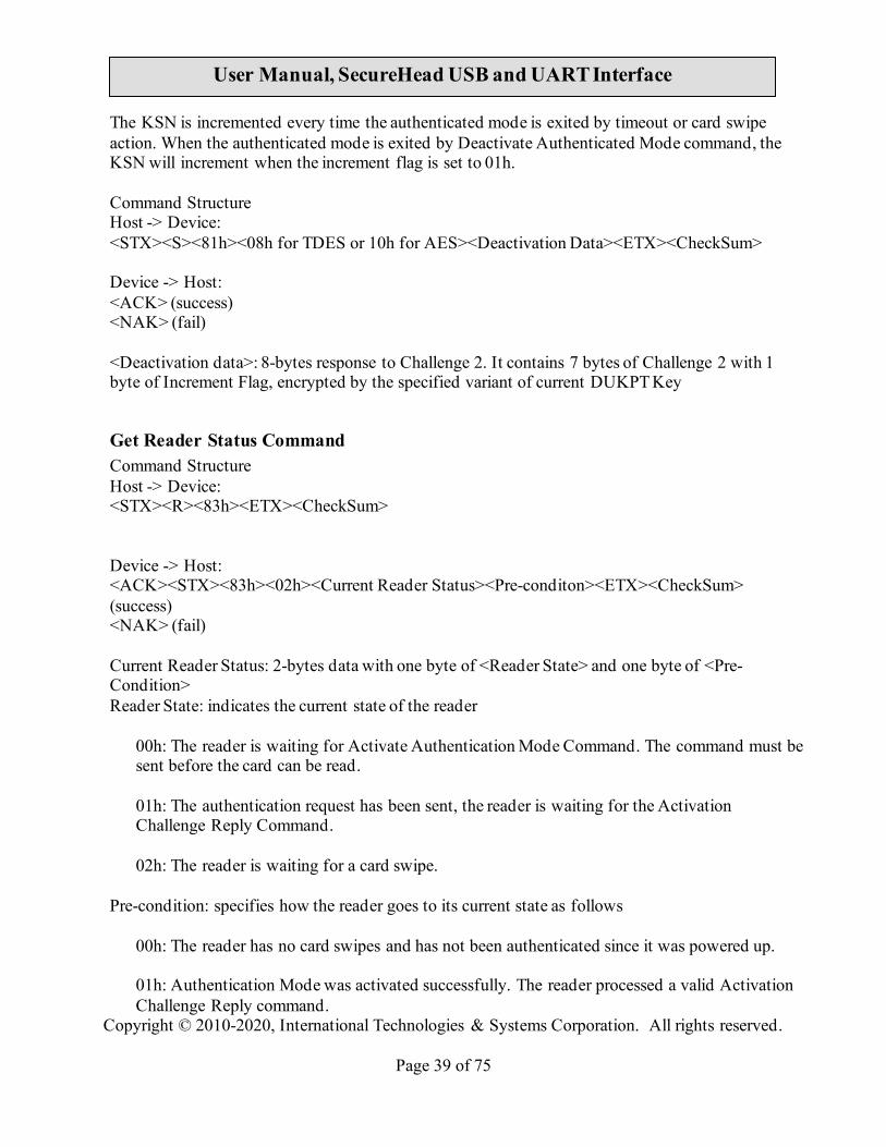
The KSN is incremented every time the authenticated mode is exited by timeout or card swipe action. When the authenticated mode is exited by Deactivate Authenticated Mode command, the KSN will increment when the increment flag is set to 01h.
Command Structure Host -> Device: <STX><S><81h><08h for TDES or 10h for AES><Deactivation Data><ETX><CheckSum>
Device -> Host: <ACK> (success) <NAK> (fail)
<Deactivation data>: 8-bytes response to Challenge 2. It contains 7 bytes of Challenge 2 with 1 byte of Increment Flag, encrypted by the specified variant of current DUKPT Key
Get Reader Status Command Command Structure Host -> Device: <STX><R><83h><ETX><CheckSum> Device -> Host: <ACK><STX><83h><02h><Current Reader Status><Pre-conditon><ETX><CheckSum> (success) <NAK> (fail) Current Reader Status: 2-bytes data with one byte of <Reader State> and one byte of <Pre-Condition> Reader State: indicates the current state of the reader
00h: The reader is waiting for Activate Authentication Mode Command. The command must be sent before the card can be read. 01h: The authentication request has been sent, the reader is waiting for the Activation Challenge Reply Command. 02h: The reader is waiting for a card swipe.
Pre-condition: specifies how the reader goes to its current state as follows
00h: The reader has no card swipes and has not been authenticated since it was powered up. 01h: Authentication Mode was activated successfully. The reader processed a valid Activation Challenge Reply command.

Copyright © 2010-2020, International Technologies & Systems Corporation. All rights reserved.
Page 40 of 75
User Manual, SecureHead USB and UART Interface
02h: The reader receives a good card swipe. 03h: The reader receives a bad card swipe or the card is invalid. 04h: Authentication Activation Failed. 05h: Authentication Deactivation Failed. 06h: Authentication Activation Timed Out. The Host fails to send an Activation Challenge Reply command within the time specified in the Activate Authentication Mode command. 07h: Swipe Timed Out. The user fails to swipe a card within the time specified in the Activation Challenge Reply command.
4.9. Other Command Protocol Settings
4.9.1. Set/Get Device Serial Number Set/Get eight byte device serial number. Command: Set Device Serial Number: 01 00 0B 00 01 01 <8 bytes of Device Serial Number> Get Device Serial Number: 01 00 03 00 00 01 Command Response: Set Device Serial Number: 01 00 02 01 00 Get Device Serial Number: 01 00 0A 01 00 <8 bytes of Device Serial Number >
4.9.2. Enable/Disable Encryption Enable or Disable the SecureHead Encryption output in other mode (non-ID TECH protocol). If encryption is disabled, original data will be sent out to the host. If it enabled, encrypted data will be send out to the host Command: 01 00 04 00 01 02 01 Enable Encryption 01 00 04 00 01 02 00 Disable Encryption Command Response 01 00 02 01 00

Copyright © 2010-2020, International Technologies & Systems Corporation. All rights reserved.
Page 41 of 75
User Manual, SecureHead USB and UART Interface
4.9.3. Get Challenge Host gets 8 bytes random number from SecureHead in order to do external authentication. Command 01 00 03 00 00 04 Command Response 01 00 0A 01 00 <8 bytes of Challenge Data>
4.9.4. External Authenticate SecureHead will use this command to authenticate the host by comparing the decrypted data from the host with its random data. Command Format: 01 00 06 00 05 <First four bytes of decrypted random data from Get Challenge> Command Response 01 00 02 01 00 Success 01 00 02 01 01 Fail
4.9.5. Load Security Key The sixteen bytes key is used encryption, and its default value is 0000 0000 0000 0000 0000 0000 0000 0000. For security purpose, key injection only allowed after successful external authentication, and will be loaded by two components each with 16 bytes of key. Those two components will be XORed to generate key for encryption. Command Format 01 00 13 00 04 01 <16 bytes of First Key Component> 01 00 13 00 04 02 <16 bytes of Second Key Component> Command Response 01 00 02 01 00

Copyright © 2010-2020, International Technologies & Systems Corporation. All rights reserved.
Page 42 of 75
User Manual, SecureHead USB and UART Interface
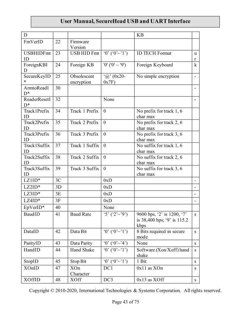
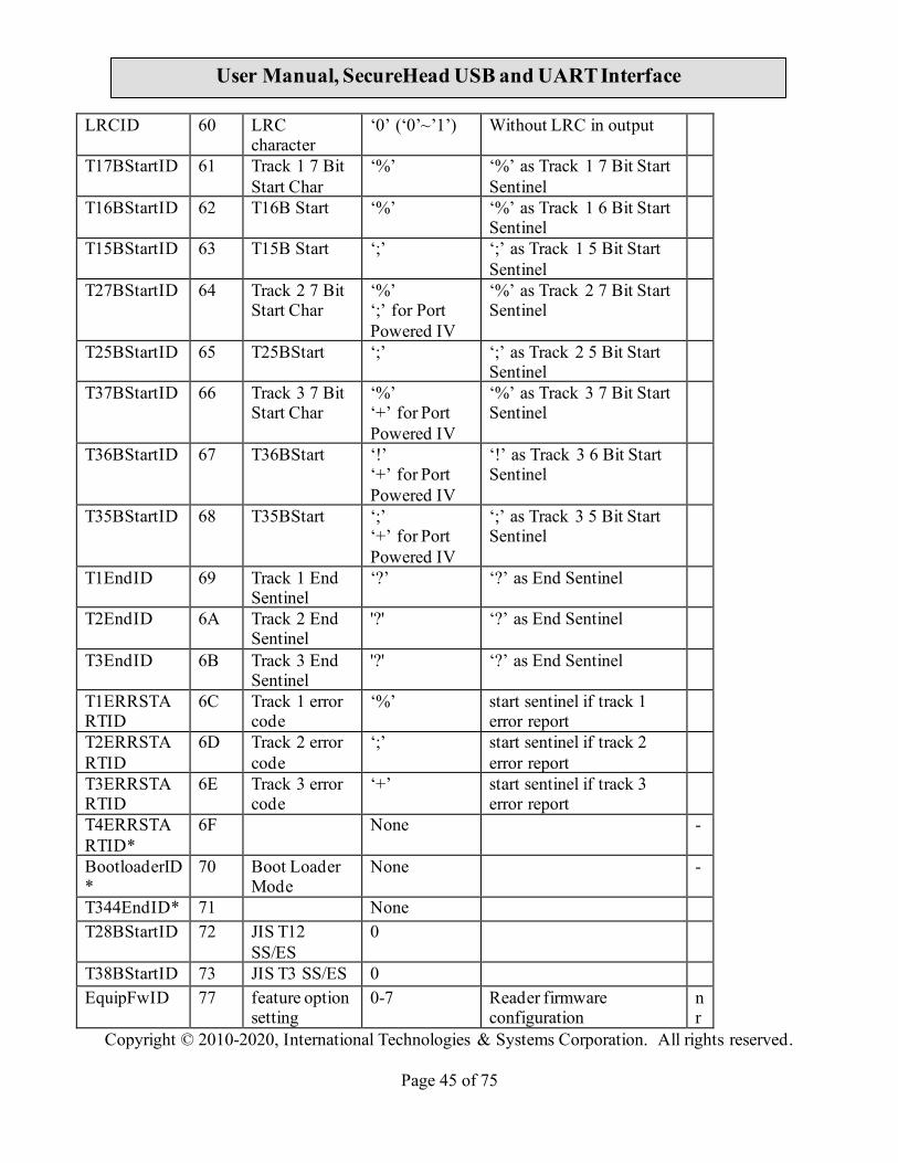
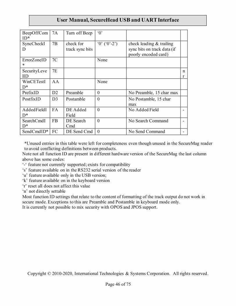
Appendix A Setting Parameters and Values Following is a table of default setting and available settings (value within parentheses) for each function ID.
Function ID Hex Description Default
Setting Description
HTypeID* 10 Terminal Type
'0' (‘0’~’2’,'4'~'6')
PC/AT, Scan Code Set 2, 1, 3, PC/AT with external Keyboard and PC/AT without External Keyboard
u
BeepID 11 Beep Setting ‘2’ (‘0’~’4’) Beep volume high and frequency high
ChaDelayID*
12 Character Delay
‘0’ (‘0’~’5’) 2 ms inter-character delay k
TrackSelectID
13 Track Selection
‘0’ (‘0’~’9’) Any Track 0-any; 1-7—bit 1 tk1, bit 2 tk2; bit 3 tk3. ‘8’—tk1-2; ‘9’ tk2-3
PollingIntervalID
14 Polling Interval
1 (1 ~ 255) USB HID Polling Interval u
DataFmtID 15 Data Output Format
‘0’ (‘0’~’2’) ID TECH Format; -
FmtOptionID 16 UIC, Mag-Tek
H’59’ Refer to MiniMag RS232 User’s Manual
-
TrackSepID 17 Track Separator
CR/Enter 0 for Port Powered IV
CR for RS232, Enter for KB any character supported except 00 which means none.
SendOptionID
19 Send Option ‘1’ (‘0’~’F’) ‘5’ for Port Powered IV
Sentinel and Account number control
MSRReadingID
1A MSR Reading ‘1’ (‘0’~’2’) Enable MSR Reading ‘0’ MSR disable; ‘2’ Buffer Mode
DTEnableSendID*
1B DT Enable Send
‘0’(‘0’,’1’,’3’) Data Editing Control -
DecodingMethodID
1D Decoding Direction
‘1’ (‘0’~’3’) Decoding in both direction; ‘0’ Raw data ‘2’ forward ‘3’ reverse
ReviewID 1F Review All Settings
None
TerminatorI 21 Terminator CR/Enter CR for RS232, Enter for
Copyright © 2010-2020, International Technologies & Systems Corporation. All rights reserved.
Page 43 of 75
User Manual, SecureHead USB and UART Interface
D KB FmVerID 22 Firmware
Version
USBHIDFmtID
23 USB HID Fmt ‘0’ (‘0’~’1’) ID TECH Format ur
ForeignKBID
24 Foreign KB '0' ('0' ~ '9') Foreign Keyboard k
SecureKeyID*
25 Obsolescent encryption
‘@’ (0x20-0x7F)
No simple encryption -
ArmtoReadID*
30 -
ReaderResetID*
32 None -
Track1PrefixID
34 Track 1 Prefix 0 No prefix for track 1, 6 char max
Track2PrefixID
35 Track 2 Prefix 0 No prefix for track 2, 6 char max
Track3PrefixID
36 Track 3 Prefix 0 No prefix for track 3, 6 char max
Track1SuffixID
37 Track 1 Suffix 0 No suffix for track 1, 6 char max
Track2SuffixID
38 Track 2 Suffix 0 No suffix for track 2, 6 char max
Track3SuffixID
39 Track 3 Suffix 0 No suffix for track 3, 6 char max
LZ1ID* 3C 0xD - LZ2ID* 3D 0xD - LZ3ID* 3E 0xD - LZ4ID* 3F 0xD - EpVerID* 40 None BaudID 41 Baud Rate ‘5’ (‘2’~’9’) 9600 bps, ‘2’ is 1200, ‘7’
is 38,400 bps; ‘9’ is 115.2 kbps
s
DataID 42 Data Bit ‘0’ (‘0’~’1’) 8 Bits required in secure mode
s
ParityID 43 Data Parity ‘0’ (‘0’~’4’) None s HandID 44 Hand Shake ‘0’ (‘0’~’1’) Software (Xon/Xoff) hand
shake s
StopID 45 Stop Bit ‘0’ (‘0’~’1’) 1 Bit s XOnID 47 XOn
Character DC1 0x11 as XOn s
XOffID 48 XOff DC3 0x13 as XOff s

Copyright © 2010-2020, International Technologies & Systems Corporation. All rights reserved.
Page 44 of 75
User Manual, SecureHead USB and UART Interface
Character PrePANID 49 PAN to not
mask 4 (0-6) # leading PAN digits to
display
PostPANID 4A PAN to not mask
4 (0-4) # of trailing PAN digits to display
MaskCharID 4B mask the PAN with this character
‘*’ 20-7E any printable character
CrypTypeID 4C encryption type
‘1’ (‘1’-‘2’) ‘1’ 3DES ‘2’ AES r
OutputModeID
4D Std, OPOS or JPOS
'0' ('0' ~ '1') Standard mode
SerialNumberID
4E device serial # any 8 bytes 8 hex digit serial number r
DispExpDateID,
50 mask or display expiration date
'0''0'-'1' ‘1’ don’t mask expiration date
CapsCaseID* 51 None DataSeqID* 52 None StartCharID* 53 None SessionID 54 8 byte hex not
stored in EEPROM
None always init to all ‘FF’
Mod10ID 55 include mod10 check digit
'0' '0'-'2' don’t include mod10, ‘1’ display mod10, ‘2’ display wrong mod10
DesKeyID 56 DES Key Value
0 internal use only rn
AesKeyID 57 AES Key Value
0 internal use only rn
KeyManageTypeID
58 DUKPT ‘1’(‘0’-‘1’) ‘0’ fixed key
T1GENERICFMTID*
59 None
T2GENERICFMTID*
5A None
T3GENERICFMTID*
5B None
HashOptID, 5C '3' (‘0’-‘7’) Send tk1-2 hash bit 0:1 send tk1 hash; bit 1:1 send tk2 hash; bit2:1 send tk3 hash.
HexCaseID, 5D '0' (‘0’-‘1’) k
Copyright © 2010-2020, International Technologies & Systems Corporation. All rights reserved.
Page 45 of 75
User Manual, SecureHead USB and UART Interface
LRCID 60 LRC character
‘0’ (‘0’~’1’) Without LRC in output
T17BStartID 61 Track 1 7 Bit Start Char
‘%’ ‘%’ as Track 1 7 Bit Start Sentinel
T16BStartID 62 T16B Start ‘%’ ‘%’ as Track 1 6 Bit Start Sentinel
T15BStartID 63 T15B Start ‘;’ ‘;’ as Track 1 5 Bit Start Sentinel
T27BStartID 64 Track 2 7 Bit Start Char
‘%’ ‘;’ for Port Powered IV
‘%’ as Track 2 7 Bit Start Sentinel
T25BStartID 65 T25BStart ‘;’ ‘;’ as Track 2 5 Bit Start Sentinel
T37BStartID 66 Track 3 7 Bit Start Char
‘%’ ‘+’ for Port Powered IV
‘%’ as Track 3 7 Bit Start Sentinel
T36BStartID 67 T36BStart ‘!’ ‘+’ for Port Powered IV
‘!’ as Track 3 6 Bit Start Sentinel
T35BStartID 68 T35BStart ‘;’ ‘+’ for Port Powered IV
‘;’ as Track 3 5 Bit Start Sentinel
T1EndID 69 Track 1 End Sentinel
‘?’ ‘?’ as End Sentinel
T2EndID 6A Track 2 End Sentinel
'?' ‘?’ as End Sentinel
T3EndID 6B Track 3 End Sentinel
'?' ‘?’ as End Sentinel
T1ERRSTARTID
6C Track 1 error code
‘%’ start sentinel if track 1 error report
T2ERRSTARTID
6D Track 2 error code
‘;’ start sentinel if track 2 error report
T3ERRSTARTID
6E Track 3 error code
‘+’ start sentinel if track 3 error report
T4ERRSTARTID*
6F None -
BootloaderID *
70 Boot Loader Mode
None -
T344EndID* 71 None T28BStartID 72 JIS T12
SS/ES 0
T38BStartID 73 JIS T3 SS/ES 0 EquipFwID 77 feature option
setting 0-7 Reader firmware
configuration nr
Copyright © 2010-2020, International Technologies & Systems Corporation. All rights reserved.
Page 46 of 75
User Manual, SecureHead USB and UART Interface
BeepOffComID*
7A Turn off Beep ‘0’
SyncCheckID
7B check for track sync bits
‘0’ (‘0’-2’) check leading & trailing sync bits on track data (if poorly encoded card)
ErrorZoneID*
7C None
SecurityLevelID
7E nr
WinCETestID*
AA None
PrefixID D2 Preamble 0 No Preamble, 15 char max PostfixID D3 Postamble 0 No Postamble, 15 char
max
AddedFieldID*
FA DE Added Field
0 No Added Field -
SearchCmdID*
FB DE Search Cmd
0 No Search Command -
SendCmdID* FC DE Send Cmd 0 No Send Command - *Unused entries in this table were left for completeness even though unused in the SecureMag reader to avoid conflicting definitions between products.
Note not all function ID are present in different hardware version of the SecureMag the last column above has some codes: ‘-‘ feature not currently supported; exists for compatibility ‘s’ feature available on in the RS232 serial version of the reader ‘u’ feature available only in the USB version; ‘k’ feature available on in the keyboard version ‘r’ reset all does not affect this value ‘n’ not directly settable Most function ID settings that relate to the content of formatting of the track output do not work in secure mode. Exceptions to this are Preamble and Postamble in keyboard mode only. It is currently not possible to mix security with OPOS and JPOS support.

Copyright © 2010-2020, International Technologies & Systems Corporation. All rights reserved.
Page 47 of 75
User Manual, SecureHead USB and UART Interface
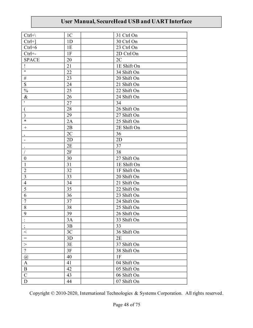
Appendix B Key Code Table in USB Keyboard Interface For most characters, "Shift On" and "Without Shift" will be reverse if Caps Lock is on. Firmware needs to check current Caps Lock status before sending out data. For Function code B1 to BA, if "Num Lock" is not set, then set it and clear it after finishing sending out code. For Function code BB to C2, C9 to CC, if "Num Lock" is set then clear it and set it after finishing sending out code.
Keystroke Hex Value
Functional Code
USB KB Code
Ctrl+2 00 1F Ctrl On Ctrl+A 01 04 Ctrl On Ctrl+B 02 05 Ctrl On Ctrl+C 03 06 Ctrl On Ctrl+D 04 07 Ctrl On Ctrl+E 05 08 Ctrl On Ctrl+F 06 09 Ctrl On Ctrl+G 07 0A Ctrl On BS 08 \bs 2A Tab 09 \tab 2B Ctrl+J 0A 0D Ctrl On Ctrl+K 0B 0E Ctrl On Ctrl+L 0C 0F Ctrl On Enter 0D \enter 28 Ctrl+N 0E 11 Ctrl On Ctrl+O 0F 12 Ctrl On Ctrl+P 10 13 Ctrl On Ctrl+Q 11 14 Ctrl On Ctrl+R 12 15 Ctrl On Ctrl+S 13 16 Ctrl On Ctrl+T 14 17 Ctrl On Ctrl+U 15 18 Ctrl On Ctrl+V 16 19 Ctrl On Ctrl+W 17 1A Ctrl On Ctrl+X 18 1B Ctrl On Ctrl+Y 19 1C Ctrl On Ctrl+Z 1A 1D Ctrl On ESC 1B \esc 29
Copyright © 2010-2020, International Technologies & Systems Corporation. All rights reserved.
Page 48 of 75
User Manual, SecureHead USB and UART Interface
Ctrl+\ 1C 31 Ctrl On Ctrl+] 1D 30 Ctrl On Ctrl+6 1E 23 Ctrl On Ctrl+- 1F 2D Ctrl On SPACE 20 2C ! 21 1E Shift On " 22 34 Shift On # 23 20 Shift On $ 24 21 Shift On % 25 22 Shift On & 26 24 Shift On ' 27 34 ( 28 26 Shift On ) 29 27 Shift On * 2A 25 Shift On + 2B 2E Shift On , 2C 36 - 2D 2D . 2E 37 / 2F 38 0 30 27 Shift On 1 31 1E Shift On 2 32 1F Shift On 3 33 20 Shift On 4 34 21 Shift On 5 35 22 Shift On 6 36 23 Shift On 7 37 24 Shift On 8 38 25 Shift On 9 39 26 Shift On : 3A 33 Shift On ; 3B 33 < 3C 36 Shift On = 3D 2E > 3E 37 Shift On ? 3F 38 Shift On @ 40 1F A 41 04 Shift On B 42 05 Shift On C 43 06 Shift On D 44 07 Shift On

Copyright © 2010-2020, International Technologies & Systems Corporation. All rights reserved.
Page 49 of 75
User Manual, SecureHead USB and UART Interface
E 45 08 Shift On F 46 09 Shift On G 47 0A Shift On H 48 0B Shift On I 49 0C Shift On J 4A 0D Shift On K 4B 0E Shift On L 4C 0F Shift On M 4D 10 Shift On N 4E 11 Shift On O 4F 12 Shift On P 50 13 Shift On Q 51 14 Shift On R 52 15 Shift On S 53 16 Shift On T 54 17 Shift On U 55 18 Shift On V 56 19 Shift On W 57 1A Shift On X 58 1B Shift On Y 59 1C Shift On Z 5A 1D Shift On [ 5B 2F \ 5C 31 ] 5D 30 ^ 5E 23 Shift On _ 5F 2D Shift On ` 60 35 a 61 04 b 62 05 c 63 06 d 64 07 e 65 08 f 66 09 g 67 0A h 68 0B i 69 0C j 6A 0D k 6B 0E l 6C 0F m 6D 10

Copyright © 2010-2020, International Technologies & Systems Corporation. All rights reserved.
Page 50 of 75
User Manual, SecureHead USB and UART Interface
n 6E 11 o 6F 12 p 70 13 q 71 14 r 72 15 s 73 16 t 74 17 u 75 18 v 76 19 w 77 1A x 78 1B y 79 1C z 7A 1D { 7B 2F Shift On | 7C 31 Shift On } 7D 30 Shift On ~ 7E 35 Shift On DEL 7F 2A F1 81 \f1 3A F2 82 \f2 3B F3 83 \f3 3C F4 84 \f4 3D F5 85 \f5 3E F6 86 \f6 3F F7 87 \f7 40 F8 88 \f8 41 F9 89 \f9 42 F10 8A \fa 43 F11 8B \fb 44 F12 8C \fc 45 Home 8D \home 4A End 8E \end 4D → 8F \right 4F ← 90 \left 50 ↑ 91 \up 52 ↓ 92 \down 51 PgUp 93 \pgup 4B PgDn 94 \pgdn 4E Tab 95 \tab 2B bTab 96 \btab 2B Shift On

Copyright © 2010-2020, International Technologies & Systems Corporation. All rights reserved.
Page 51 of 75
User Manual, SecureHead USB and UART Interface
Esc 97 \esc 29 Enter 98 \enter 28 Num_Enter 99 \num_enter 58 Delete 9A \del 4C Insert 9B \ins 49 Backspace 9C \bs 2A SPACE 9D \sp 2C Pause 9C \ps 48 Ctrl+[ 9F \ctr1 2F Ctrl On Ctrl+] A0 \ctr2 30 Ctrl On Ctrl+\ A1 \ctr3 31 Ctrl On Left_Ctrl_Break A2 \l_ctrl_bk Clear Ctrl Flag Left_Ctrl_Make A3 \l_ctrl_mk Set Ctrl Flag for following char(s) Left_Shift_Break A4 \l_shift_bk Clear Shift Flag Left_Shift_Make A5 \l_shift_mk Set Shift Flag for following
char(s) Left_Windows A6 \l_windows E3 (left GUI) Left_Alt_Break A7 \l_alt_bk Clear Alt Flag Left_Alt_Make A8 \l_alt_mk Set Alt Flag for following char(s) Right_Ctrl_Break A9 \r_ctrl_bk Clear Ctrl Flag Right_Ctrl_Make AA \r_ctrl_mk Set Ctrl Flag for following char(s) Right_Shift_Break AB \r_shift_bk Clear Shift Flag Right_Shift_Make AC \r_shift_mk Set Shift Flag for following
char(s) Right_Windows AD \r_windows E7 (right GUI) Right_Alt_Break AE \r_alt_bk Clear Alt Flag Right_Alt_Make AF \r_alt_mk Set Alt Flag for following char(s) Num_Lock B0 \num_lock 53 Num_0 B1 \num0 62 Num Lock On Num_1 B2 \num1 59 Num Lock On Num_2 B3 \num2 5A Num Lock On Num_3 B4 \num3 5B Num Lock On Num_4 B5 \num4 5C Num Lock On Num_5 B6 \num5 5D Num Lock On Num_6 B7 \num6 5E Num Lock On Num_7 B8 \num7 5F Num Lock On Num_8 B9 \num8 60 Num Lock On Num_9 BA \num9 61 Num Lock On Num_Home BB \num_home 5F Num_PageUp BC \num_pgup 61

Copyright © 2010-2020, International Technologies & Systems Corporation. All rights reserved.
Page 52 of 75
User Manual, SecureHead USB and UART Interface
Num_PageDown BD \num_pgdn 5B Num_End BE \num_end 59 Num_↑ BF \num_up 60 Num_→ C0 \num_right 5E Num_↓ C1 \num_down 5A Num_← C2 \num_left 5C Print_Scrn C3 \prt_sc 46 System_Request C4 \sysrq 9A Scroll_Lock C5 \scroll 47 Pause C6 \menu 76 Break C7 \break Caps_Lock C8 \caps_lock 39 Num_/ C9 \num_/ 54 Num_* CA \num_* 55 Num_- CB \num_- 56 Num_+ CC \num_+ 57 Num_. CD \num_. 63 Num Lock On Num_DEL CE \num_del 63 Num_INS CF \num_ins 62 Delay_100ms D0 \delay Delay 100 ms
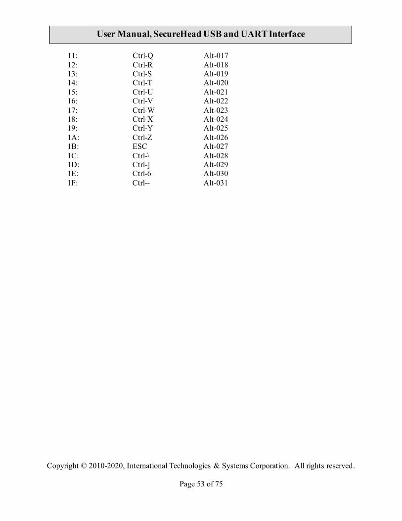
Table of Ctrl or Alt output for non printable characters ASCII Code Control Code Alt Code SendOptionID Bit 3: 0 Bit 3: 1 00: Ctrl-2 Alt-000 01: Ctrl-A Alt-001 02: Ctrl-B Alt-002 03: Ctrl-C Alt-003 04: Ctrl-D Alt-004 05: Ctrl-E Alt-005 06: Ctrl-F Alt-006 07: Ctrl-G Alt-007 08: BS Alt-008 09: Tab Alt-009 0A: Ctrl-J Alt-010 0B: Ctrl-K Alt-011 0C: Ctrl-L Alt-012 0D: Enter Alt-013 0E: Ctrl-N Alt-014 0F: Ctrl-O Alt-015 10: Ctrl-P Alt-016
Copyright © 2010-2020, International Technologies & Systems Corporation. All rights reserved.
Page 53 of 75
User Manual, SecureHead USB and UART Interface
11: Ctrl-Q Alt-017 12: Ctrl-R Alt-018 13: Ctrl-S Alt-019 14: Ctrl-T Alt-020 15: Ctrl-U Alt-021 16: Ctrl-V Alt-022 17: Ctrl-W Alt-023 18: Ctrl-X Alt-024 19: Ctrl-Y Alt-025 1A: Ctrl-Z Alt-026 1B: ESC Alt-027 1C: Ctrl-\ Alt-028 1D: Ctrl-] Alt-029 1E: Ctrl-6 Alt-030 1F: Ctrl-- Alt-031

Copyright © 2010-2020, International Technologies & Systems Corporation. All rights reserved.
Page 54 of 75
User Manual, SecureHead USB and UART Interface
Appendix C Default Setting Table Default Setting Table MSR Reading Enable Decoding Method Both Swiping Direction
Decode mode Track Separator Settings CR Terminator Settings CR Preamble Settings None Postamble Settings None Track Selected Settings Any Track Sentinel and T2 Account No Send Sentinels and all T2
data Data Edit Setting Disabled Track Prefix None Track Suffix None

Copyright © 2010-2020, International Technologies & Systems Corporation. All rights reserved.
Page 55 of 75
User Manual, SecureHead USB and UART Interface
Appendix D Magnetic Stripe Standard Formats ISO Credit Card Format ISO stands for International Standards Organization Track 1 Field ID Character
Contents Length
a Start Sentinel 1 b Format Code “B” 1 c Account Number 12 or 19 d Separator “^” 1 e Cardholder Name variable f Separator “^” 1 g Expiration date 4 h Optional Discretionary data variable i End Sentinel 1 j Linear Redundancy Check
(LRC) Character 1
Track 2 a Start Sentinel 1 b Account Number 12 or 19 c Separator “=” 1 d Expiration date “YYMM” 4 e Optional discretionary data variable f End Sentinel 1 g Linear Redundancy Check
(LRC) Character 1

Copyright © 2010-2020, International Technologies & Systems Corporation. All rights reserved.
Page 56 of 75
User Manual, SecureHead USB and UART Interface
AAMVA Driver’s License Format Track 1 a Start Sentinel 1 b State or Province 2 c City 13 d Name 35 e Address 29 f End Sentinel 1 g Linear Redundancy Check
(LRC) Character 1
Track 2 a Start Sentinel 1 b ANSI User Code 1 c ANSI User ID 5 d Jurisdiction ID/DL 14 e Expiration date 4 f Birth Date 8 g Remainder of Jurisdiction ID/DL 5 h End Sentinel 1 I Linear Redundancy Check
(LRC) Character 1
Track 3 a Start Sentinel 1 b Template Version # 1 c Security Version # 1 d Postal Code 11 e Class 2 f Restrictions 10 g Endorsements 4 h Sex 1 I Height 3 j Weight 3 k Hair Color 3 l Eye Color 3 m ID # 10 n Reserved Space 16 o Error Correction 6 p Security 5 q End Sentinel 1

Copyright © 2010-2020, International Technologies & Systems Corporation. All rights reserved.
Page 57 of 75
User Manual, SecureHead USB and UART Interface
r Linear Redundancy Check (LRC) Character
1

Copyright © 2010-2020, International Technologies & Systems Corporation. All rights reserved.
Page 58 of 75
User Manual, SecureHead USB and UART Interface
Appendix E Other Mode Card Data Output There is an optional data output format supported by SecureHead in order to be compatible with specific software requirement. <01h> <01h> <1Ah> <02h> <00h> <Left 8 bytes Device Serial Number> <6 Byte Random data> <30h> <31h> <264 bytes of Sampling data>.
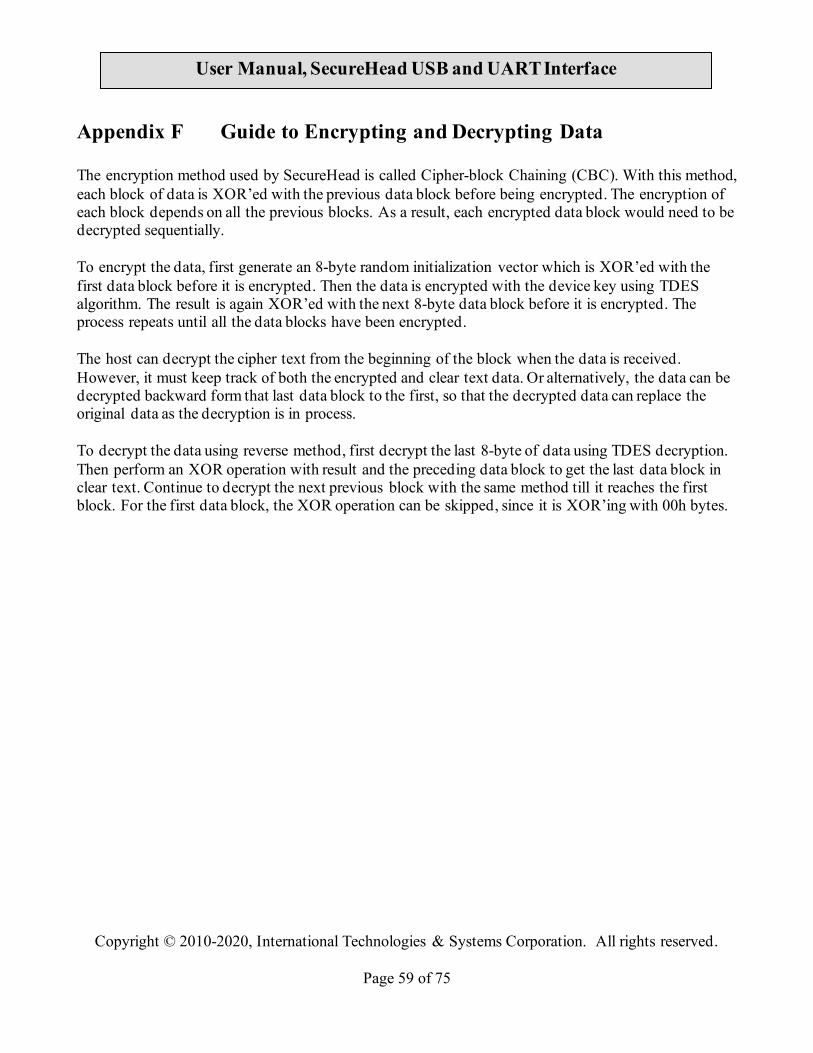
Copyright © 2010-2020, International Technologies & Systems Corporation. All rights reserved.
Page 59 of 75
User Manual, SecureHead USB and UART Interface
Appendix F Guide to Encrypting and Decrypting Data The encryption method used by SecureHead is called Cipher-block Chaining (CBC). With this method, each block of data is XOR’ed with the previous data block before being encrypted. The encryption of each block depends on all the previous blocks. As a result, each encrypted data block would need to be decrypted sequentially. To encrypt the data, first generate an 8-byte random initialization vector which is XOR’ed with the first data block before it is encrypted. Then the data is encrypted with the device key using TDES algorithm. The result is again XOR’ed with the next 8-byte data block before it is encrypted. The process repeats until all the data blocks have been encrypted. The host can decrypt the cipher text from the beginning of the block when the data is received. However, it must keep track of both the encrypted and clear text data. Or alternatively, the data can be decrypted backward form that last data block to the first, so that the decrypted data can replace the original data as the decryption is in process. To decrypt the data using reverse method, first decrypt the last 8-byte of data using TDES decryption. Then perform an XOR operation with result and the preceding data block to get the last data block in clear text. Continue to decrypt the next previous block with the same method till it reaches the first block. For the first data block, the XOR operation can be skipped, since it is XOR’ing with 00h bytes.

Copyright © 2010-2020, International Technologies & Systems Corporation. All rights reserved.
Page 60 of 75
User Manual, SecureHead USB and UART Interface
Appendix G Key Management Flow Chart

Copyright © 2010-2020, International Technologies & Systems Corporation. All rights reserved.
Page 61 of 75
User Manual, SecureHead USB and UART Interface
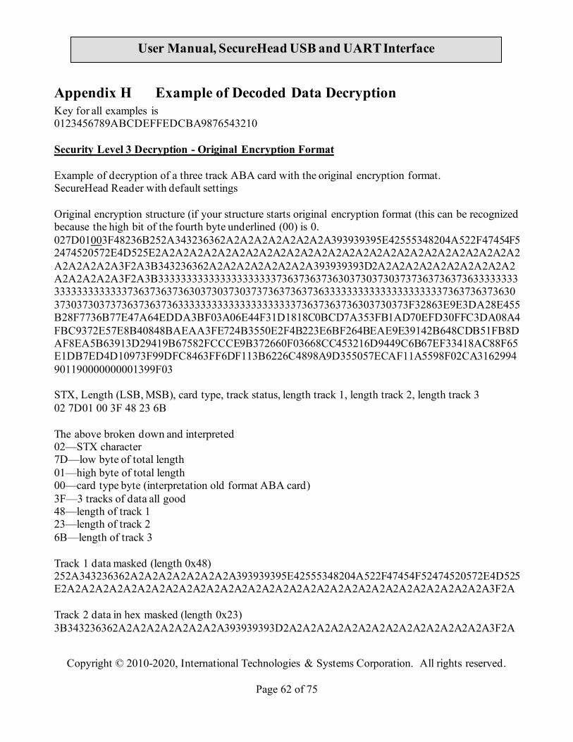
Copyright © 2010-2020, International Technologies & Systems Corporation. All rights reserved.
Page 62 of 75
User Manual, SecureHead USB and UART Interface
Appendix H Example of Decoded Data Decryption Key for all examples is 0123456789ABCDEFFEDCBA9876543210 Security Level 3 Decryption - Original Encryption Format Example of decryption of a three track ABA card with the original encryption format. SecureHead Reader with default settings Original encryption structure (if your structure starts original encryption format (this can be recognized because the high bit of the fourth byte underlined (00) is 0. 027D01003F48236B252A343236362A2A2A2A2A2A2A2A393939395E42555348204A522F47454F52474520572E4D525E2A2A2A2A2A2A2A2A2A2A2A2A2A2A2A2A2A2A2A2A2A2A2A2A2A2A2A2A2A2A2A3F2A3B343236362A2A2A2A2A2A2A2A393939393D2A2A2A2A2A2A2A2A2A2A2A2A2A2A2A3F2A3B33333333333333333333373637363736303730373037373637363736333333333333333333333736373637363037303730373736373637363333333333333333333337363736373630373037303737363736373633333333333333333333373637363736303730373F32863E9E3DA28E455B28F7736B77E47A64EDDA3BF03A06E44F31D1818C0BCD7A353FB1AD70EFD30FFC3DA08A4FBC9372E57E8B40848BAEAA3FE724B3550E2F4B223E6BF264BEAE9E39142B648CDB51FB8DAF8EA5B63913D29419B67582FCCCE9B372660F03668CC453216D9449C6B67EF33418AC88F65E1DB7ED4D10973F99DFC8463FF6DF113B6226C4898A9D355057ECAF11A5598F02CA3162994901190000000001399F03 STX, Length (LSB, MSB), card type, track status, length track 1, length track 2, length track 3 02 7D01 00 3F 48 23 6B The above broken down and interpreted 02—STX character 7D—low byte of total length 01—high byte of total length 00—card type byte (interpretation old format ABA card) 3F—3 tracks of data all good 48—length of track 1 23—length of track 2 6B—length of track 3 Track 1 data masked (length 0x48) 252A343236362A2A2A2A2A2A2A2A393939395E42555348204A522F47454F52474520572E4D525E2A2A2A2A2A2A2A2A2A2A2A2A2A2A2A2A2A2A2A2A2A2A2A2A2A2A2A2A2A2A2A3F2A Track 2 data in hex masked (length 0x23) 3B343236362A2A2A2A2A2A2A2A393939393D2A2A2A2A2A2A2A2A2A2A2A2A2A2A2A3F2A

Copyright © 2010-2020, International Technologies & Systems Corporation. All rights reserved.
Page 63 of 75
User Manual, SecureHead USB and UART Interface
Track 3 data unencrypted (length 0x6B) 3B33333333333333333333373637363736303730373037373637363736333333333333333333333736373637363037303730373736373637363333333333333333333337363736373630373037303737363736373633333333333333333333373637363736303730373F32 Track 1 & 2 encrypted length 0x48+0x23 rounded up to 8 bytes =0x6B -> 0x70 (112 decimal) 863E9E3DA28E455B28F7736B77E47A64EDDA3BF03A06E44F31D1818C0BCD7A35 3FB1AD70EFD30FFC3DA08A4FBC9372E57E8B40848BAEAA3FE724B3550E2F4B22 3E6BF264BEAE9E39142B648CDB51FB8DAF8EA5B63913D29419B67582FCCCE9B3 72660F03668CC453216D9449C6B67EF3 Track 1 hashed 3418AC88F65E1DB7ED4D10973F99DFC8463FF6DF Track 2 hashed 113B6226C4898A9D355057ECAF11A5598F02CA31 KSN 62994901190000000001 LRC, checksum and ETX 39 9F 03 Masked Data: Track 1 data masked in ASCII: %*4266********9999^BUSH JR/GEORGE W.MR^*******************************?* Track 2 data masked in ASCII: ;4266********9999=***************?* Track 3 data unencrypted in ASCII: ;33333333337676760707077676763333333333767676070707767676333333333376767607070776767633333333337676760707?2 Key Value: F8 2A 7A 0D 7C 67 46 F1 96 18 9A FB 54 2C 65 A3 KSN: 62 99 49 01 19 00 00 00 00 01 Decrypted Data in ASCII: %B4266841088889999^BUSH JR/GEORGE W.MR^0809101100001100000000046000000?!;4266841088889999=080910110000046?0 ;33333333337676760707077676763333333333767676070707767676333333333376767607070776767633333333337676760707?2 Decrypted Data in Hex: 2542343236363834313038383838393939395E42555348204A522F47454F52474520572E4D525E303830393130313130303030313130303030303030303034363030303030303F213B343236363834313038383838393939393D3038303931303131303030303034363F300000000000
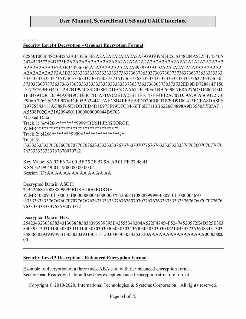
Copyright © 2010-2020, International Technologies & Systems Corporation. All rights reserved.
Page 64 of 75
User Manual, SecureHead USB and UART Interface
-=-=-=- Security Level 4 Decryption - Original Encryption Format 028501003F48236B252A343236362A2A2A2A2A2A2A2A393939395E42555348204A522F47454F52474520572E4D525E2A2A2A2A2A2A2A2A2A2A2A2A2A2A2A2A2A2A2A2A2A2A2A2A2A2A2A2A2A2A2A3F2A3B343236362A2A2A2A2A2A2A2A393939393D2A2A2A2A2A2A2A2A2A2A2A2A2A2A2A3F2A3B33333333333333333333373637363736303730373037373637363736333333333333333333333736373637363037303730373736373637363333333333333333333337363736373630373037303737363736373633333333333333333333373637363736303730373F32ED9DB728814F150D177F769B0441C52B2B1994C83D058F1DDA5DAA6753CF0F61BB7690C7E8A276D3D606513D1F8B79423C70594A0849CBB4C7B5A8DAC2B1A21B11F1C47EF4F12AC07D59A79E9369372D3F906A7F6C6D2B9076BCF05B334441FAEC8B4EFBEB9DD20EBF97B29D910C415FCEA8DA8FEB9775343418AC88F65E1DB7ED4D10973F99DFC8463FF6DF113B6226C4898A9D355057ECAF11A5598F02CA31629949011900000000044B6F03 Masked Data: Track 1: %*4266********9999^BUSH JR/GEORGE W.MR^*******************************?* Track 2: ;4266********9999=***************?* Track 3: ;33333333337676760707077676763333333333767676070707767676333333333376767607070776767633333333337676760707?2 Key Value: 8A 92 F6 74 00 BF 25 2E 57 9A A9 01 FF 27 48 41 KSN: 62 99 49 01 19 00 00 00 00 04 Session ID: AA AA AA AA AA AA AA AA Decrypted Data in ASCII: %B4266841088889999^BUSH JR/GEORGE W.MR^0809101100001100000000046000000?!;4266841088889999=080910110000046?0 ;33333333337676760707077676763333333333767676070707767676333333333376767607070776767633333333337676760707?2 Decrypted Data in Hex: 2542343236363834313038383838393939395E42555348204A522F47454F52474520572E4D525E303830393130313130303030313130303030303030303034363030303030303F213B343236363834313038383838393939393D3038303931303131303030303034363F30AAAAAAAAAAAAAAAA0000000000 Security Level 3 Decryption - Enhanced Encryption Format Example of decryption of a three track ABA card with the enhanced encryption format. SecureHead Reader with default settings except enhanced encryption structure format.

Copyright © 2010-2020, International Technologies & Systems Corporation. All rights reserved.
Page 65 of 75
User Manual, SecureHead USB and UART Interface
Enhanced encryption Format (this can be recognized because the high bit of the fourth byte underlined (80) is 1. 029801803F48236B03BF252A343236362A2A2A2A2A2A2A2A393939395E42555348204A522F47454F52474520572E4D525E2A2A2A2A2A2A2A2A2A2A2A2A2A2A2A2A2A2A2A2A2A2A2A2A2A2A2A2A2A2A2A3F2A3B343236362A2A2A2A2A2A2A2A393939393D2A2A2A2A2A2A2A2A2A2A2A2A2A2A2A3F2ADA7F2A52BD3F6DD8B96C50FC39C7E6AF22F06ED1F033BE0FB23D6BD33DC5A1F808512F7AE18D47A60CC3F4559B1B093563BE7E07459072ABF8FAAB5338C6CC8815FF87797AE3A7BEAB3B10A3FBC230FBFB941FAC9E82649981AE79F2632156E775A06AEDAFAF6F0A184318C5209E55AD44A9CCF6A78AC240F791B63284E15B4019102BA6C505814B585816CA3C2D2F42A99B1B9773EF1B116E005B7CD8681860D174E6AD316A0ECDBC687115FC89360AEE7E430140A7B791589CCAADB6D6872B78433C3A25DA9DDAE83F12FEFAB530CE405B701131D2FBAAD970248A456000933418AC88F65E1DB7ED4D10973F99DFC8463FF6DF113B6226C4898A9D355057ECAF11A5598F02CA31688861C157C1CE2E0F72CE0F3BB598A614EAABB16299490119000000000206E203 STX, Length(LSB, MSB), card type, track status, length track 1, length track 2, length track 3 02 9801 80 3F 48-23-6B 03BF The above broken down and interpreted 02—STX character 98—low byte of total length 01—high byte of total length 80—card type byte (interpretation new format ABA card) 3F—3 tracks of data all good 48—length of track 1 23—length of track 2 6B—length of track 3 03—tracks 1 and 2 have masked/clear data BF—bit 7=1—KSN included Bit 6=0—no Session ID included so not level 4 encryption Bit 5=1—track 3 hash data present Bit 4=1—track 2 hash data present Bit 3-1—track 1 hash data present Bit 2=1—track 3 encrypted data present Bit 1=1—track 2 encrypted data present Bit 0=1—track 1 encrypted data present Track 1 data masked (length 0x48) 252A343236362A2A2A2A2A2A2A2A393939395E42555348204A522F47454F52474520572E4D525E2A2A2A2A2A2A2A2A2A2A2A2A2A2A2A2A2A2A2A2A2A2A2A2A2A2A2A2A2A2A2A3F2A Track 1 masked data in ASCII

Copyright © 2010-2020, International Technologies & Systems Corporation. All rights reserved.
Page 66 of 75
User Manual, SecureHead USB and UART Interface
%*4266********9999^BUSH JR/GEORGE W.MR^*******************************?* Track 2 data in hex masked (length 0x23) 3B343236362A2A2A2A2A2A2A2A393939393D2A2A2A2A2A2A2A2A2A2A2A2A2A2A2A3F2A Track2 masked data in ASCII ;4266********9999=***************?* In this example there is no Track 3 data either clear or masked (encrypted and hashed data is below) Track 1 encrypted length 0x48 rounded up to 8 bytes = 0x48 (72 decimal) DA7F2A52BD3F6DD8B96C50FC39C7E6AF22F06ED1F033BE0FB23D6BD33DC5A1F8 08512F7AE18D47A60CC3F4559B1B093563BE7E07459072ABF8FAAB5338C6CC88 15FF87797AE3A7BE Track 2 encrypted length 0x32 rounded up to 8 bytes =0x38 (56 decimal) AB3B10A3FBC230FBFB941FAC9E82649981AE79F2632156E775A06AEDAFAF6F0A 184318C5209E55AD Track 3 encrypted length 0x6B rounded up to 8 bytes =0x70 (64 decimal) 44A9CCF6A78AC240F791B63284E15B4019102BA6C505814B585816CA3C2D2F42 A99B1B9773EF1B116E005B7CD8681860D174E6AD316A0ECDBC687115FC89360A EE7E430140A7B791589CCAADB6D6872B78433C3A25DA9DDAE83F12FEFAB530CE 405B701131D2FBAAD970248A45600093 Track 1 data hashed length 20 bytes 3418AC88F65E1DB7ED4D10973F99DFC8463FF6DF Track 2 data hashed length 20 bytes 113B6226C4898A9D355057ECAF11A5598F02CA31 Track 3 data hashed length 20 bytes 688861C157C1CE2E0F72CE0F3BB598A614EAABB1 KSN length 10 bytes 62994901190000000002 LCR, check sum and ETX 06E203 Clear/Masked Data in ASCII: Track 1: %*4266********9999^BUSH JR/GEORGE W.MR^*******************************?* Track 2: ;4266********9999=***************?*
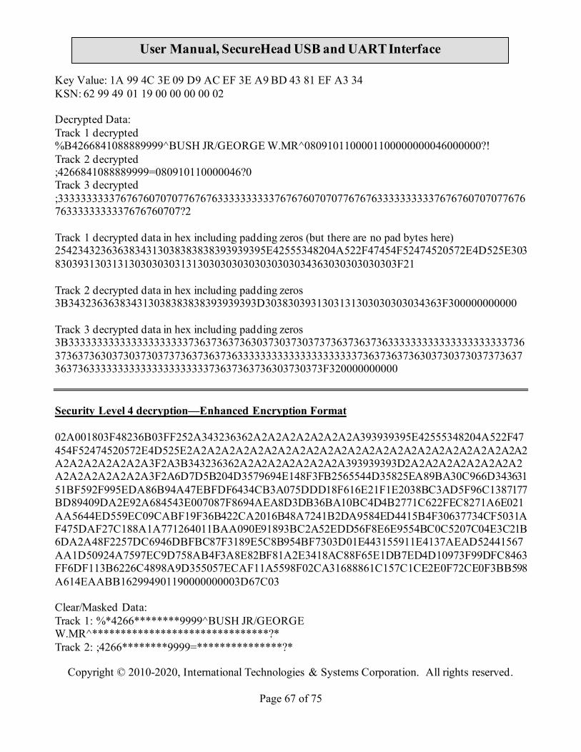
Copyright © 2010-2020, International Technologies & Systems Corporation. All rights reserved.
Page 67 of 75
User Manual, SecureHead USB and UART Interface
Key Value: 1A 99 4C 3E 09 D9 AC EF 3E A9 BD 43 81 EF A3 34 KSN: 62 99 49 01 19 00 00 00 00 02 Decrypted Data: Track 1 decrypted %B4266841088889999^BUSH JR/GEORGE W.MR^0809101100001100000000046000000?! Track 2 decrypted ;4266841088889999=080910110000046?0 Track 3 decrypted ;33333333337676760707077676763333333333767676070707767676333333333376767607070776767633333333337676760707?2 Track 1 decrypted data in hex including padding zeros (but there are no pad bytes here) 2542343236363834313038383838393939395E42555348204A522F47454F52474520572E4D525E303830393130313130303030313130303030303030303034363030303030303F21 Track 2 decrypted data in hex including padding zeros 3B343236363834313038383838393939393D3038303931303131303030303034363F300000000000 Track 3 decrypted data in hex including padding zeros 3B33333333333333333333373637363736303730373037373637363736333333333333333333333736373637363037303730373736373637363333333333333333333337363736373630373037303737363736373633333333333333333333373637363736303730373F320000000000 Security Level 4 decryption—Enhanced Encryption Format 02A001803F48236B03FF252A343236362A2A2A2A2A2A2A2A393939395E42555348204A522F47454F52474520572E4D525E2A2A2A2A2A2A2A2A2A2A2A2A2A2A2A2A2A2A2A2A2A2A2A2A2A2A2A2A2A2A2A3F2A3B343236362A2A2A2A2A2A2A2A393939393D2A2A2A2A2A2A2A2A2A2A2A2A2A2A2A3F2A6D7D5B204D3579694E148F3FB2565544D35825EA89BA30C966D34363151BF592F995EDA86B94A47EBFDF6434CB3A075DDD18F616E21F1E2038BC3AD5F96C1387177BD89409DA2E92A684543E007087F8694AEA8D3DB36BA10BC4D4B2771C622FEC8271A6E021AA5644ED559EC09CABF19F36B422CA2016B48A7241B2DA9584ED4415B4F30637734CF5031AF475DAF27C188A1A771264011BAA090E91893BC2A52EDD56F8E6E9554BC0C5207C04E3C21B6DA2A48F2257DC6946DBFBC87F3189E5C8B954BF7303D01E443155911E4137AEAD52441567AA1D50924A7597EC9D758AB4F3A8E82BF81A2E3418AC88F65E1DB7ED4D10973F99DFC8463FF6DF113B6226C4898A9D355057ECAF11A5598F02CA31688861C157C1CE2E0F72CE0F3BB598A614EAABB162994901190000000003D67C03 Clear/Masked Data: Track 1: %*4266********9999^BUSH JR/GEORGE W.MR^*******************************?* Track 2: ;4266********9999=***************?*

Copyright © 2010-2020, International Technologies & Systems Corporation. All rights reserved.
Page 68 of 75
User Manual, SecureHead USB and UART Interface
Key Value: 89 52 50 33 61 75 51 5C 41 20 CF 45 F4 1A BF 1C KSN: 62 99 49 01 19 00 00 00 00 03 Session ID: AA AA AA AA AA AA AA AA Decrypted Data in ASCII: %B4266841088889999^BUSH JR/GEORGE W.MR^0809101100001100000000046000000?! ;4266841088889999=080910110000046?0 ;33333333337676760707077676763333333333767676070707767676333333333376767607070776767633333333337676760707?2 Decrypted Data in Hex 2542343236363834313038383838393939395E42555348204A522F47454F52474520572E4D525E303830393130313130303030313130303030303030303034363030303030303F21 3B343236363834313038383838393939393D3038303931303131303030303034363F300000000000 3B33333333333333333333373637363736303730373037373637363736333333333333333333333736373637363037303730373736373637363333333333333333333337363736373630373037303737363736373633333333333333333333373637363736303730373F320000000000
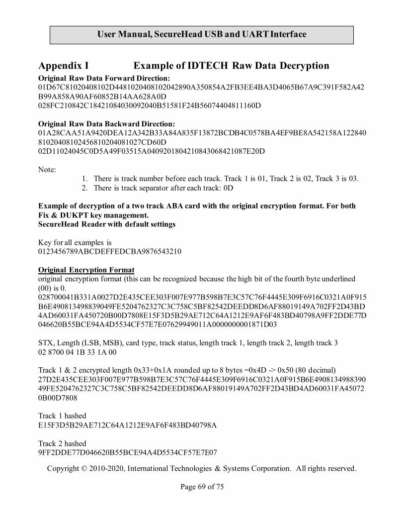
Copyright © 2010-2020, International Technologies & Systems Corporation. All rights reserved.
Page 69 of 75
User Manual, SecureHead USB and UART Interface
Appendix I Example of IDTECH Raw Data Decryption Original Raw Data Forward Direction: 01D67C81020408102D4481020408102042890A350854A2FB3EE4BA3D4065B67A9C391F582A42B99A858A90AF60852B14AA628A0D 028FC210842C18421084030092040B51581F24B56074404811160D Original Raw Data Backward Direction: 01A28CAA51A9420DEA12A342B33A84A835F13872BCDB4C0578BA4EF9BE8A542158A12284081020408102456810204081027CD60D 02D11024045C0D5A49F03515A0409201804210843068421087E20D Note:
1. There is track number before each track. Track 1 is 01, Track 2 is 02, Track 3 is 03. 2. There is track separator after each track: 0D
Example of decryption of a two track ABA card with the original encryption format. For both Fix & DUKPT key management. SecureHead Reader with default settings Key for all examples is 0123456789ABCDEFFEDCBA9876543210 Original Encryption Format original encryption format (this can be recognized because the high bit of the fourth byte underlined (00) is 0. 028700041B331A0027D2E435CEE303F007E977B598B7E3C57C76F4445E309F6916C0321A0F915B6E490813498839049FE5204762327C3C758C5BF82542DEEDD8D6AF88019149A702FF2D43BD4AD60031FA450720B00D7808E15F3D5B29AE712C64A1212E9AF6F483BD40798A9FF2DDE77D046620B55BCE94A4D5534CF57E7E07629949011A0000000001871D03 STX, Length (LSB, MSB), card type, track status, length track 1, length track 2, length track 3 02 8700 04 1B 33 1A 00 Track 1 & 2 encrypted length 0x33+0x1A rounded up to 8 bytes =0x4D -> 0x50 (80 decimal) 27D2E435CEE303F007E977B598B7E3C57C76F4445E309F6916C0321A0F915B6E490813498839049FE5204762327C3C758C5BF82542DEEDD8D6AF88019149A702FF2D43BD4AD60031FA450720B00D7808 Track 1 hashed E15F3D5B29AE712C64A1212E9AF6F483BD40798A Track 2 hashed 9FF2DDE77D046620B55BCE94A4D5534CF57E7E07

Copyright © 2010-2020, International Technologies & Systems Corporation. All rights reserved.
Page 70 of 75
User Manual, SecureHead USB and UART Interface
KSN 629949011A0000000001 LRC, checksum and ETX 87 1D 03 Key Value: 8A 60 A3 EB 80 87 63 52 B8 F5 05 CD A8 3C 33 70 KSN: 62 99 49 01 1A 00 00 00 00 01 Decrypted Raw Data: 01D67C81020408102D4481020408102042890A350854A2FB3EE4BA3D4065B67A9C391F582A42B99A858A90AF60852B14AA628A 028FC210842C18421084030092040B51581F24B5607440481116 -=-=-=--=-=-=--=-=-=--=-=-=--=-=-=--=-=-=--=-=-=--=-=-=--=-=-=--=-=-=--=-=-=--=-=-=--=-=-=--=- Security Level 4 Original Encryption Format 028F00041B331A0070756B86C0B670DAAA78EEA454F5A7BAFB5CDA91BA9A5B62BB49F67CD21484D3138DB3468C80F3468688AE61E3FB25FEEB630B81717CC405F8A73430FCAFEF98C4CEDE76AB7AAC0D9090E2B25F7E77F7888306B57CB67A9BE15F3D5B29AE712C64A1212E9AF6F483BD40798A9FF2DDE77D046620B55BCE94A4D5534CF57E7E07629949011A0000000002DD5D03 Key Value: 06 A9 B3 23 2A 69 B4 57 61 76 5E C3 CB A3 33 37 KSN: 62 99 49 01 1A 00 00 00 00 02 Session ID: AA AA AA AA AA AA AA AA Decrypted Data: 01D67C81020408102D4481020408102042890A350854A2FB3EE4BA3D4065B67A9C391F582A42B99A858A90AF60852B14AA628A 028FC210842C18421084030092040B51581F24B5607440481116
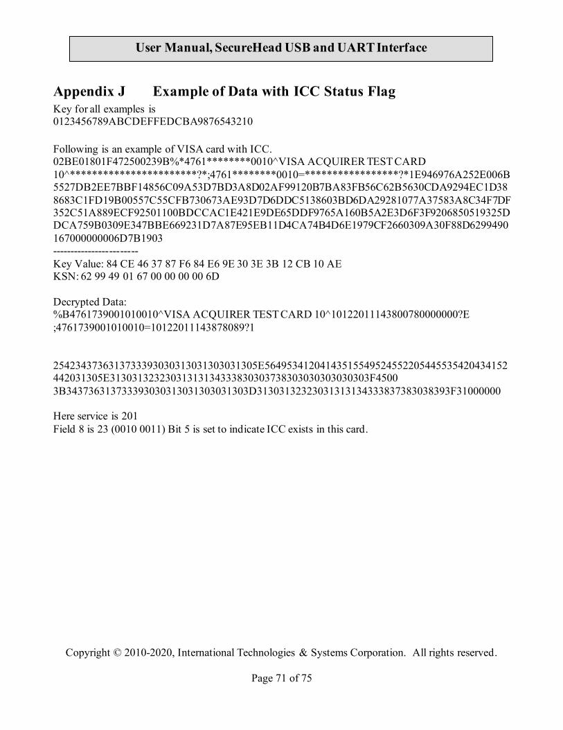
Copyright © 2010-2020, International Technologies & Systems Corporation. All rights reserved.
Page 71 of 75
User Manual, SecureHead USB and UART Interface
Appendix J Example of Data with ICC Status Flag Key for all examples is 0123456789ABCDEFFEDCBA9876543210 Following is an example of VISA card with ICC. 02BE01801F472500239B%*4761********0010^VISA ACQUIRER TEST CARD 10^***********************?*;4761********0010=*****************?*1E946976A252E006B5527DB2EE7BBF14856C09A53D7BD3A8D02AF99120B7BA83FB56C62B5630CDA9294EC1D388683C1FD19B00557C55CFB730673AE93D7D6DDC5138603BD6DA29281077A37583A8C34F7DF352C51A889ECF92501100BDCCAC1E421E9DE65DDF9765A160B5A2E3D6F3F9206850519325DDCA759B0309E347BBE669231D7A87E95EB11D4CA74B4D6E1979CF2660309A30F88D6299490167000000006D7B1903 ------------------------ Key Value: 84 CE 46 37 87 F6 84 E6 9E 30 3E 3B 12 CB 10 AE KSN: 62 99 49 01 67 00 00 00 00 6D Decrypted Data: %B4761739001010010^VISA ACQUIRER TEST CARD 10^10122011143800780000000?E ;4761739001010010=10122011143878089?1 2542343736313733393030313031303031305E56495341204143515549524552205445535420434152442031305E31303132323031313134333830303738303030303030303F4500 3B343736313733393030313031303031303D31303132323031313134333837383038393F31000000 Here service is 201 Field 8 is 23 (0010 0011) Bit 5 is set to indicate ICC exists in this card.
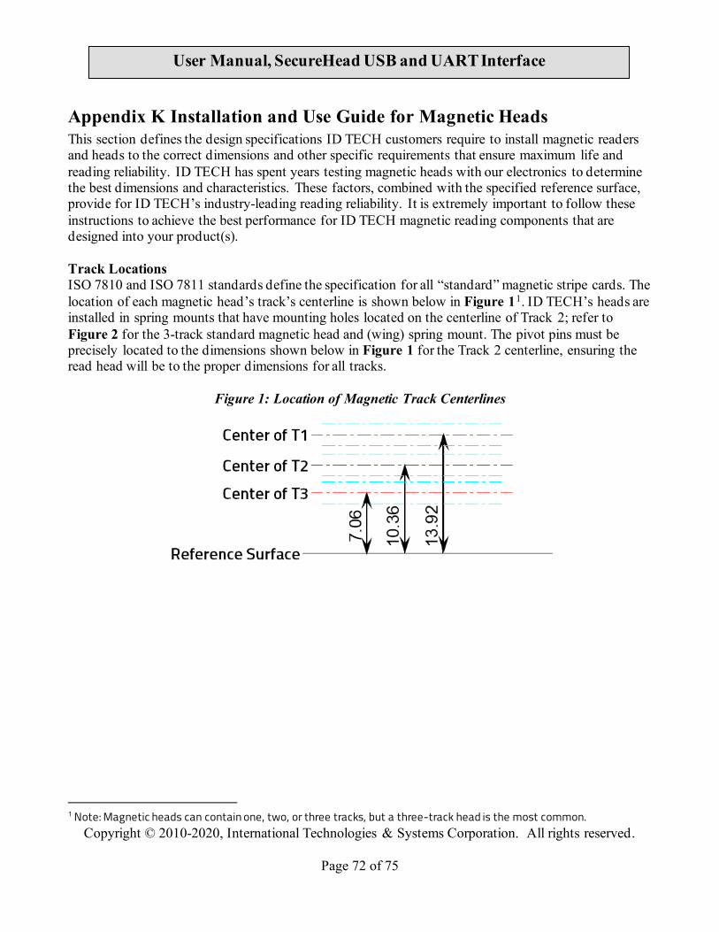
Copyright © 2010-2020, International Technologies & Systems Corporation. All rights reserved.
Page 72 of 75
User Manual, SecureHead USB and UART Interface
Appendix K Installation and Use Guide for Magnetic Heads This section defines the design specifications ID TECH customers require to install magnetic readers and heads to the correct dimensions and other specific requirements that ensure maximum life and reading reliability. ID TECH has spent years testing magnetic heads with our electronics to determine the best dimensions and characteristics. These factors, combined with the specified reference surface, provide for ID TECH’s industry-leading reading reliability. It is extremely important to follow these instructions to achieve the best performance for ID TECH magnetic reading components that are designed into your product(s). Track Locations ISO 7810 and ISO 7811 standards define the specification for all “standard” magnetic stripe cards. The location of each magnetic head’s track’s centerline is shown below in Figure 11. ID TECH’s heads are installed in spring mounts that have mounting holes located on the centerline of Track 2; refer to Figure 2 for the 3-track standard magnetic head and (wing) spring mount. The pivot pins must be precisely located to the dimensions shown below in Figure 1 for the Track 2 centerline, ensuring the read head will be to the proper dimensions for all tracks.
Figure 1: Location of Magnetic Track Centerlines
1 Note: Magnetic heads can contain one, two, or three tracks, but a three-track head is the most common.
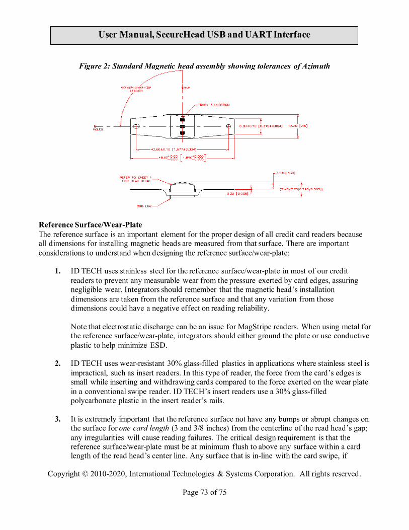
Copyright © 2010-2020, International Technologies & Systems Corporation. All rights reserved.
Page 73 of 75
User Manual, SecureHead USB and UART Interface
Figure 2: Standard Magnetic head assembly showing tolerances of Azimuth
Reference Surface/Wear-Plate The reference surface is an important element for the proper design of all credit card readers because all dimensions for installing magnetic heads are measured from that surface. There are important considerations to understand when designing the reference surface/wear-plate:
1. ID TECH uses stainless steel for the reference surface/wear-plate in most of our credit readers to prevent any measurable wear from the pressure exerted by card edges, assuring negligible wear. Integrators should remember that the magnetic head’s installation dimensions are taken from the reference surface and that any variation from those dimensions could have a negative effect on reading reliability. Note that electrostatic discharge can be an issue for MagStripe readers. When using metal for the reference surface/wear-plate, integrators should either ground the plate or use conductive plastic to help minimize ESD.
2. ID TECH uses wear-resistant 30% glass-filled plastics in applications where stainless steel is impractical, such as insert readers. In this type of reader, the force from the card’s edges is small while inserting and withdrawing cards compared to the force exerted on the wear plate in a conventional swipe reader. ID TECH’s insert readers use a 30% glass-filled polycarbonate plastic in the insert reader’s rails.
3. It is extremely important that the reference surface not have any bumps or abrupt changes on the surface for one card length (3 and 3/8 inches) from the centerline of the read head’s gap; any irregularities will cause reading failures. The critical design requirement is that the reference surface/wear-plate must be at minimum flush to above any surface within a card length of the read head’s center line. Any surface that is in-line with the card swipe, if

Copyright © 2010-2020, International Technologies & Systems Corporation. All rights reserved.
Page 74 of 75
User Manual, SecureHead USB and UART Interface
plastic, should at a minimum be of 30% glass-filled plastic because the card’s edge will inevitably scrape that surface upon entering and exiting the card swipe. We recommend having stainless steel surfaces on both the entrance and exit area surfaces or have them substantially below the rail’s reference surface.
Card Reader Rails/Slot and Magnetic Head Protrusion When designing a card reader, engineers must consider the thickness of the media used. Magnetic media comes in various thicknesses, but most readers use cards that are nominally 0.030 inches thick +/- 10%2. Some applications do occur where the media is thinner, normally in specialized applications where the media can be as thin as 0.010 inches thick (such as the paper cards used for many parking lot paper tickets). To accommodate media with minimum and maximum thicknesses, the slot needs to be a between 0.040 and 0.050 inches wide in an area a minimum of 0.5 inches on either side of the centerline of the magnetic head’s gap (this gap is located at the apex of the head’s radius). The remaining portion of the rails (slot width) can be wider, but never smaller; also remember that it is best to have the reference surface/wear-plate extend for a minimum of 1.5 inches from the magnetic head’s gap.
1. Magnetic heads need to be able to rotate on a gimbal (refer to Figure 3 for an example) to compensate for tilting cards, and therefore must have a minimum deflection. For credit/debit cards used in financial transactions or other applications using standard thickness cards (0.030 inches +/- 10%), the magnetic head’s gap (the apex of the protruding radius) should be spaced within 0.010 +/- 0.003 inches from the opposing rail/wall.
To ensure reliable read rates on thinner cards, the head must contact the media and be deflected by a minimum of 0.007 inches (0.18mm); this is regardless of the media thickness, or head configuration. For example, if the media is 0.010 inches (0.25mm) thick, the head face must be positioned a maximum of 0.003 inches (0.08mm) from the opposite wall. To avoid damaging the gap material the head should not contact the opposing rail/surface in the card slot.
2 Note: 0.030-inch thickness is the dimension for all credit and debit cards, and is common for other cards as well.

Copyright © 2010-2020, International Technologies & Systems Corporation. All rights reserved.
Page 75 of 75
User Manual, SecureHead USB and UART Interface
2. If the rails are designed without using an ID TECH rail, the minimum slot width should be
0.040 inches wide, at a minimum of 0.5 inches on both sides of the magnetic head’s gap. There must also be a smooth transition leading up to the 0.040-inch-wide area of the slot both entering and exiting the magnetic head.
Figure 3
3. When designing insert style readers, make sure the magnetic media on cards can be inserted completely, past the read head, so the reader registers the stop sentinel on the magnetic stripe.
GIMBAL IN and OUT


