Page 1
User Manual
User ManualVersion V2.4-20200421
User ManualFor BX Series GNSS Receiver©2020 Tersus GNSS Inc. All rights reserved.
Sales & Technical Support:[email protected] & [email protected] details, please visit www.tersus-gnss.com
Page 2
User Manual for BX Series GNSS Receiver v2.4
I
Revision History
Rev Description Date Owner
1.0 Issued for Review 2018/06/29 CB
2.0
In section 1.2, add OEM board of BX316 and BX316R, addBX316D enclosure;In section 1.2.7, remove external SD card for BX316 andBX316R enclosure;In chapter 2, update pictures, links, tables and commands;In section 4, list technical specifications for all BX seriesproducts;In section 5.1, update rules for the file name;In section 5.6, change RS05B radio to RS460 radio,update commands for outputting base position.
2019/03/14 LC
2.1 Updated section 5.2 download file steps 2019/04/19 LC
2.2Mark BX316 & BX316R in both OEM board and enclosureas EOL products.Change the side panel of BX306 enclosure.
2019/08/22 LC
2.3
Updated section 2.8 heading output;Added notice of normal hot surface during operation;Updated photos for real objects and connections;Added PPK accuracy for BX306 & BX316D.
2019/09/11 LC
2.4Added Table 4.12~4.16 for 20pin external cable.Updated photo, input voltage and mechanical drawing ofBX306 enclosure.
2020/04/21 LC
Page 3
User Manual for BX Series GNSS Receiver v2.4
II
Table of Content
Revision History............................................................................................................ I
Table of Content.......................................................................................................... II
List of Figures.............................................................................................................VI
List of Tables............................................................................................................... X
Notices.......................................................................................................................... 1
1. Introduction............................................................................................................4
1.1 Overview of BX Series GNSS Receivers..................................................4
1.1.1 BX GNSS OEM Boards........................................................................4
1.1.2 BX GNSS Enclosures...........................................................................4
1.2 Related documents and information..........................................................5
1.2.1 BX306 OEM Board................................................................................5
1.2.2 BX306Z OEM Board.............................................................................7
1.2.3 BX316 OEM Board (EOL)....................................................................9
1.2.4 BX316R OEM Board (EOL)...............................................................11
1.2.5 BX316D OEM Board.......................................................................... 12
1.2.6 BX306 Enclosure................................................................................ 14
1.2.7 BX316 Enclosure (EOL).....................................................................15
1.2.8 BX316R Enclosure (EOL)..................................................................17
1.2.9 BX316D Enclosure..............................................................................19
1.3 BX Receivers System Overview.............................................................. 21
1.3.1 BX Series OEM Boards......................................................................22
1.3.2 BX Enclosures.....................................................................................22
1.3.3 Antenna................................................................................................ 23
Page 4
User Manual for BX Series GNSS Receiver v2.4
III
1.3.4 Power Supply.......................................................................................23
1.3.5 Communication Equipment............................................................... 23
1.3.6 Internal eMMC Card/External SD Card...........................................23
1.3.7 Enable Heading...................................................................................24
2. Installation........................................................................................................... 25
2.1 Shipping Box...............................................................................................25
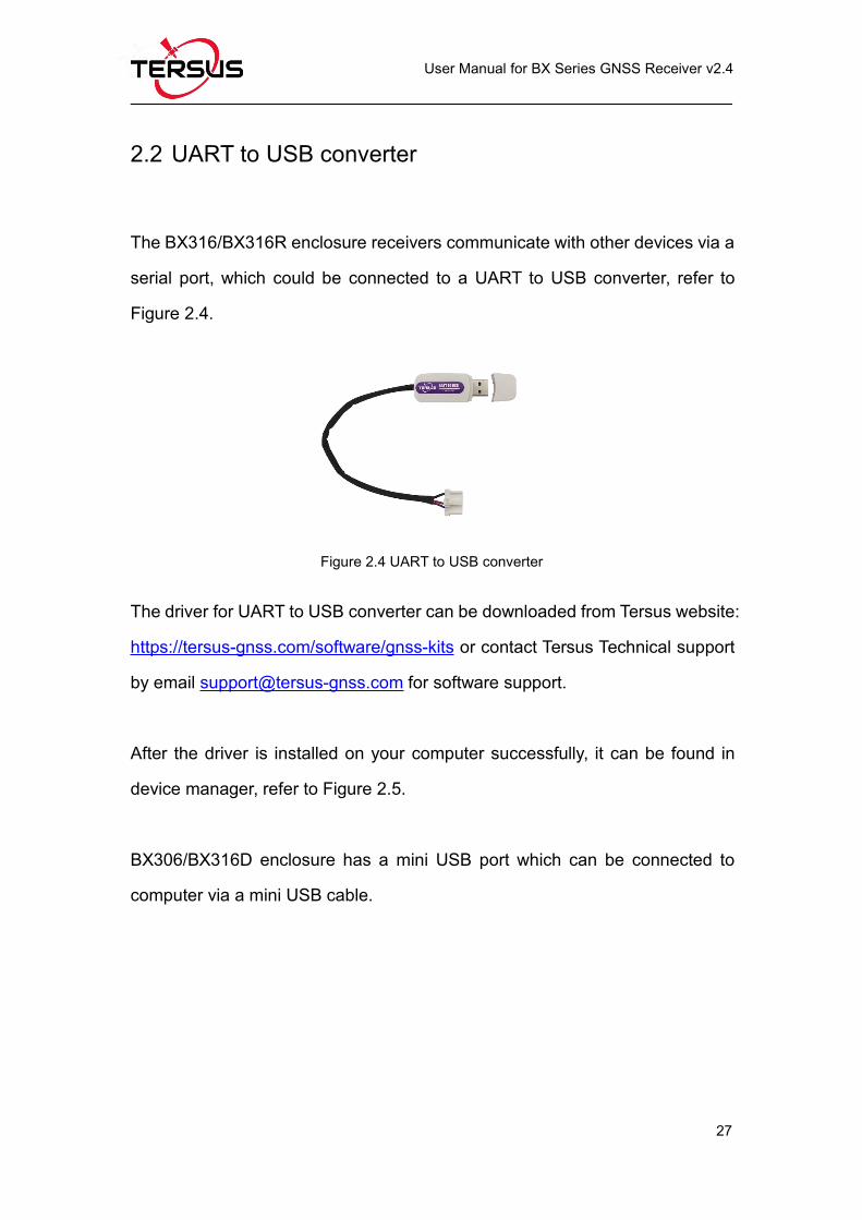
2.2 UART to USB converter............................................................................ 27
2.3 Selecting a GNSS antenna.......................................................................28
2.4 Power Supply Requirement......................................................................30
2.5 OEM Boards Installation Overview..........................................................31
2.6 Tersus GNSS Center Software................................................................ 32
2.6.1 Auto Base Station List Function........................................................35
2.7 Transmitting and Receiving Corrections.................................................36
2.8 Heading Output...........................................................................................38
3. Firmware Update and Auth Code....................................................................46
3.1 Firmware Update Overview...................................................................... 46
3.2 Firmware Update Using Tersus GNSS Center...................................... 47
3.3 Auth Code....................................................................................................52
4. Technical Specifications....................................................................................53
4.1 BX306 Board...............................................................................................53
4.1.1 BX306 Specifications..........................................................................53
4.1.2 Connectors on BX306 board.............................................................56
4.1.3 Reference Schematic of the Interface Board..................................57
Page 5
User Manual for BX Series GNSS Receiver v2.4
IV
4.2 BX306Z Board............................................................................................ 59
4.2.1 BX306Z Specifications.......................................................................59
4.2.2 Connectors on BX306Z board.......................................................... 62
4.3 BX316 Board (EOL)...................................................................................66
4.3.1 BX316 Specifications..........................................................................66
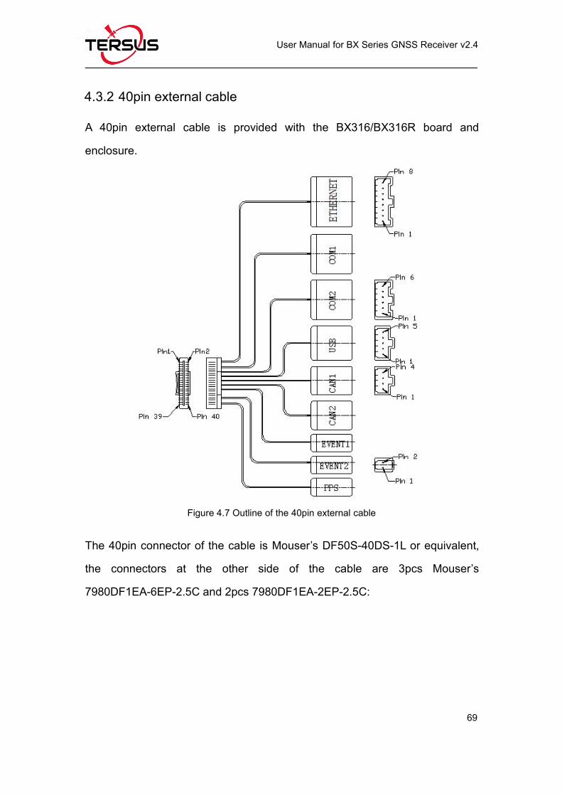
4.3.2 40pin external cable............................................................................69
4.4 BX316R Board (EOL)................................................................................ 71
4.4.1 BX316R Specifications.......................................................................71
4.4.2 40pin external cable............................................................................72
4.5 BX316D Board............................................................................................72
4.5.1 BX316D Specifications.......................................................................72
4.5.2 Connectors on BX316D board..........................................................74
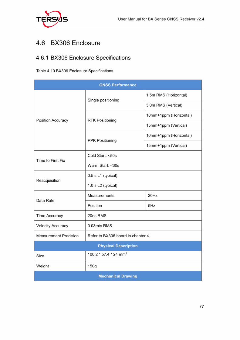
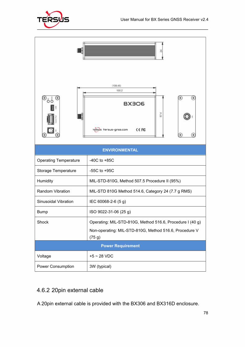
4.6 BX306 Enclosure........................................................................................77
4.6.1 BX306 Enclosure Specifications.......................................................77
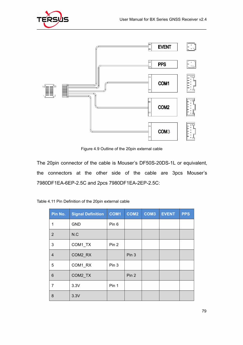
4.6.2 20pin external cable............................................................................78
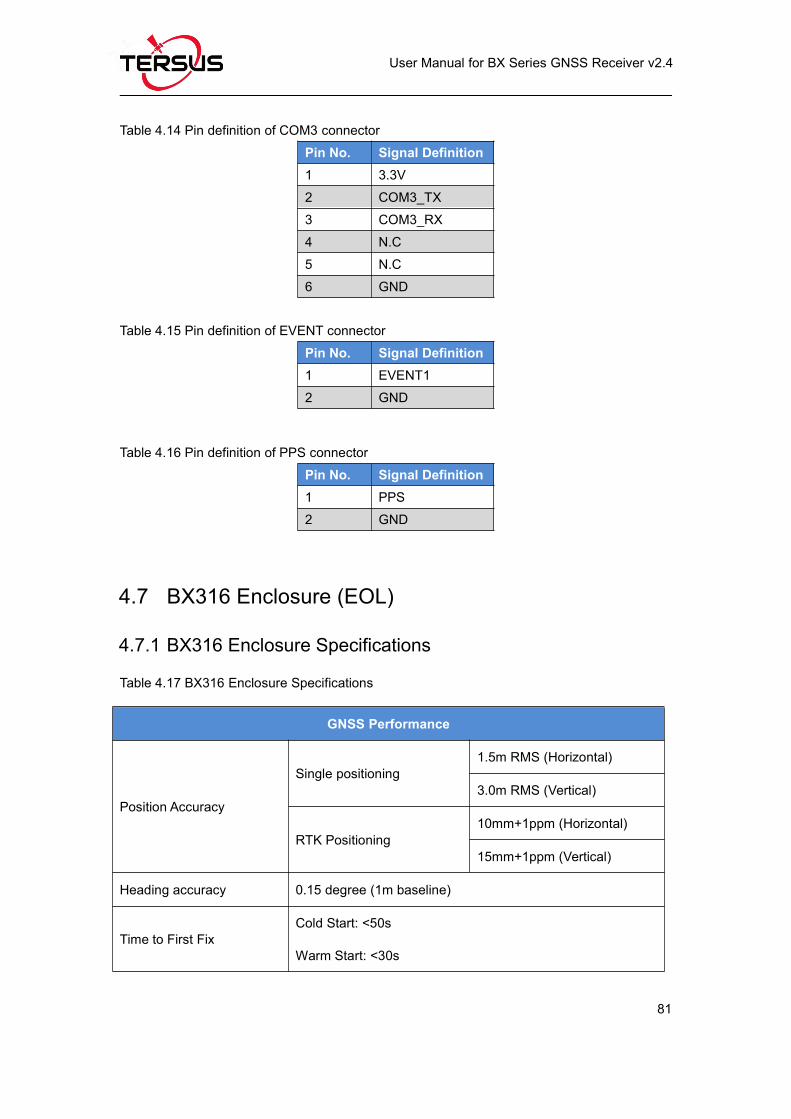
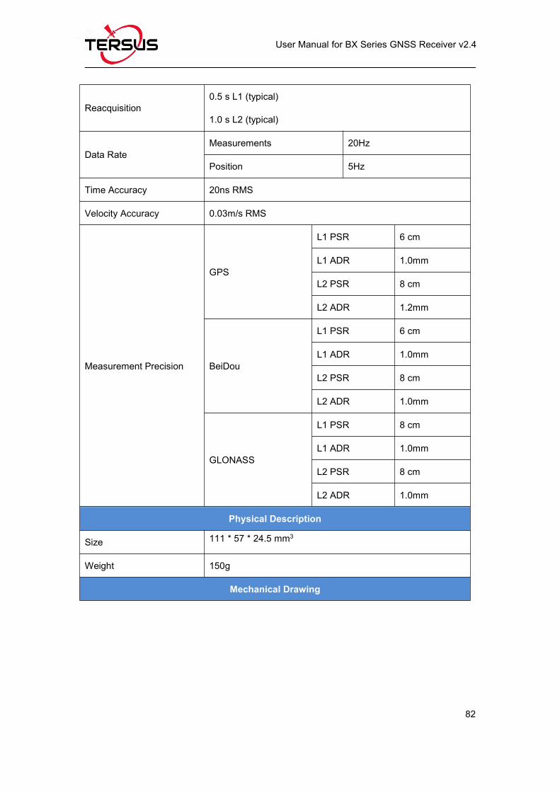
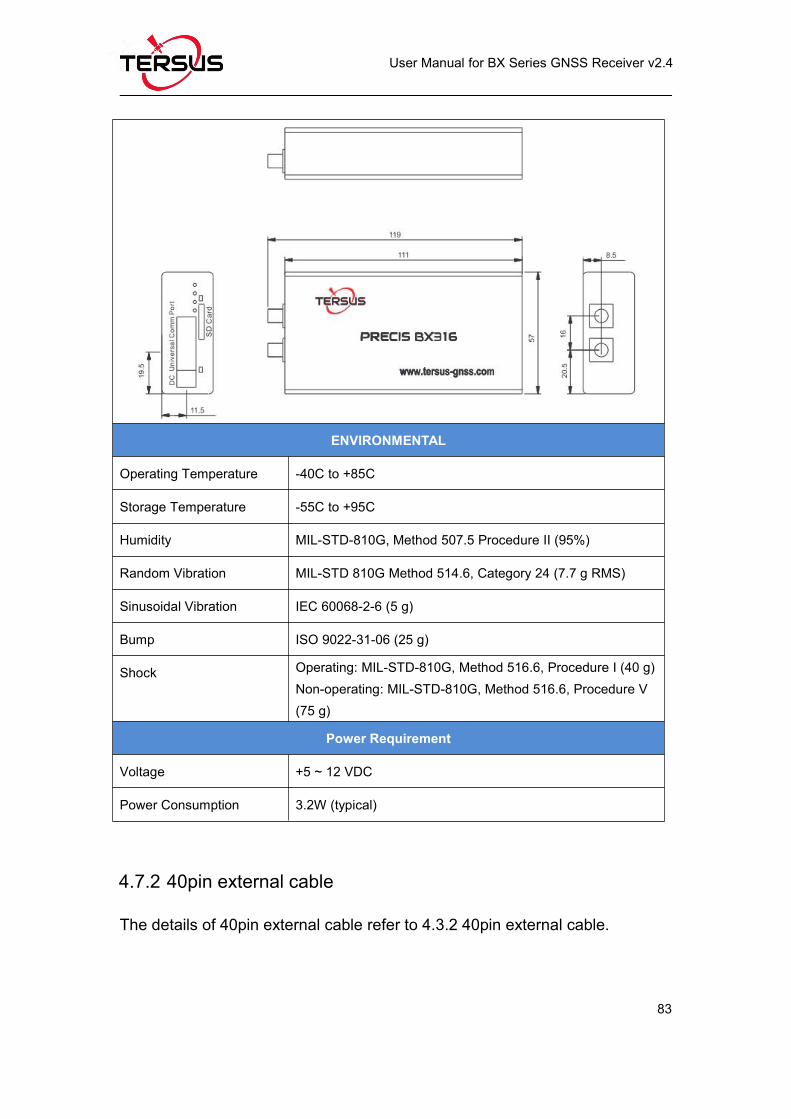
4.7 BX316 Enclosure (EOL)............................................................................81
4.7.1 BX316 Enclosure Specifications.......................................................81
4.7.2 40pin external cable............................................................................83
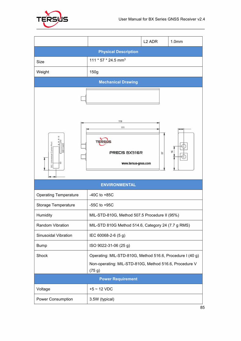
4.8 BX316R Enclosure (EOL).........................................................................84
4.8.1 BX316R Enclosure Specifications....................................................84
4.8.2 40pin external cable............................................................................86
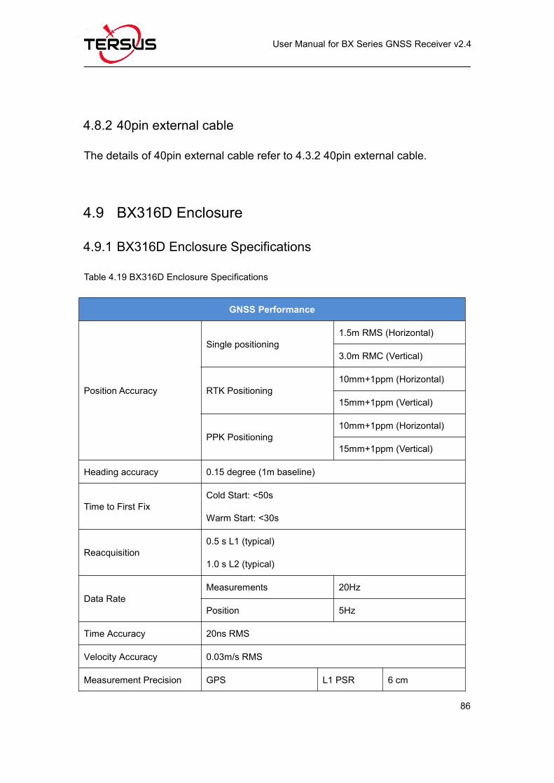
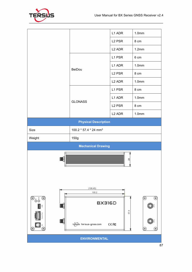
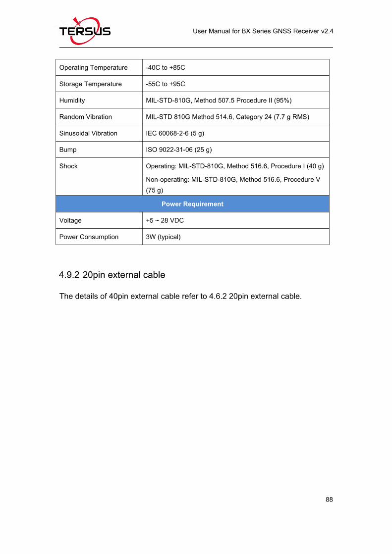
4.9 BX316D Enclosure.....................................................................................86
4.9.1 BX316D Enclosure Specifications....................................................86
Page 6
User Manual for BX Series GNSS Receiver v2.4
V
4.9.2 20pin external cable............................................................................88
5. Typical Application.............................................................................................89
5.1 Data Collection on Internal eMMC...........................................................89
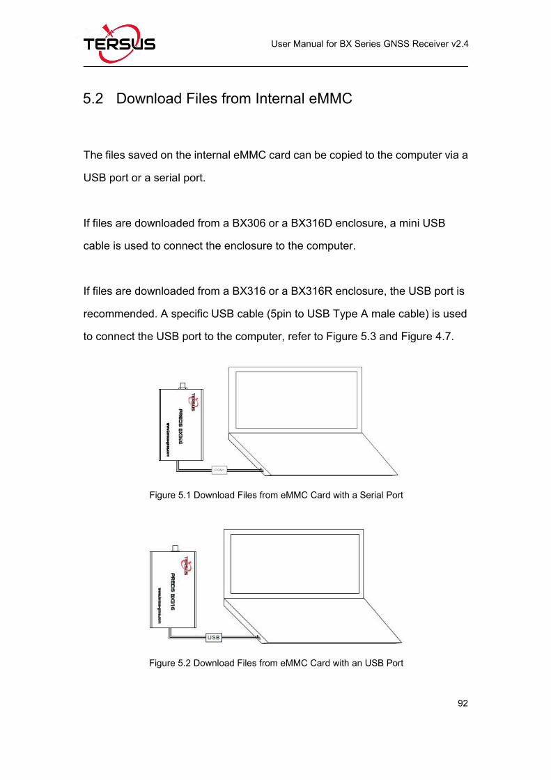
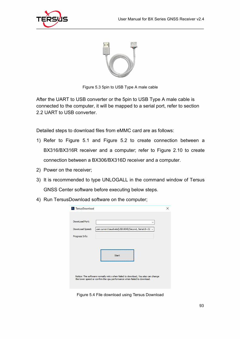
5.2 Download Files from Internal eMMC.......................................................92
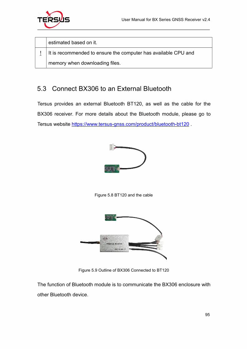
5.3 Connect BX306 to an External Bluetooth...............................................95
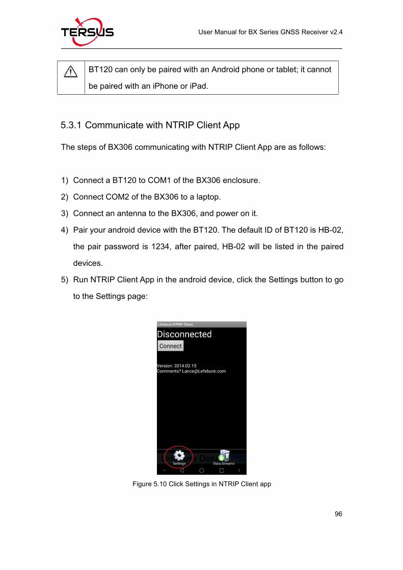
5.3.1 Communicate with NTRIP Client App..............................................96
5.4 Save Data to an External Data Logger...................................................99
5.5 Communicate with STRSVR Tool..........................................................100
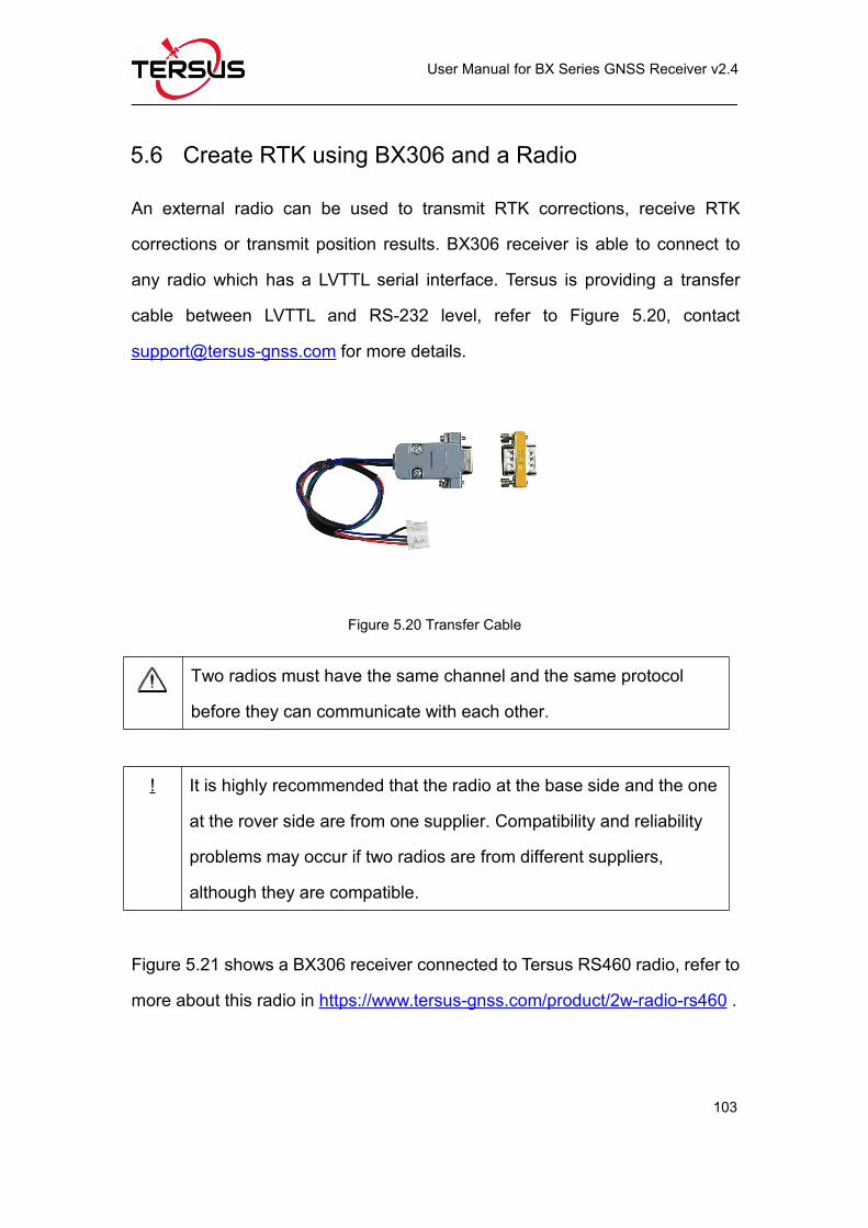
5.6 Create RTK using BX306 and a Radio.................................................103
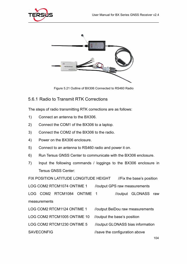
5.6.1 Radio to Transmit RTK Corrections............................................... 104
5.6.2 Radio to Receive RTK Corrections................................................105
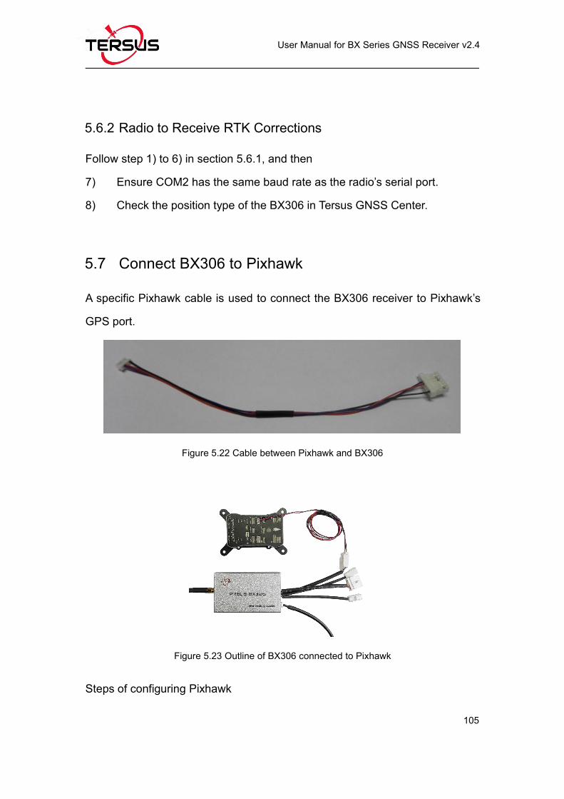
5.7 Connect BX306 to Pixhawk....................................................................105
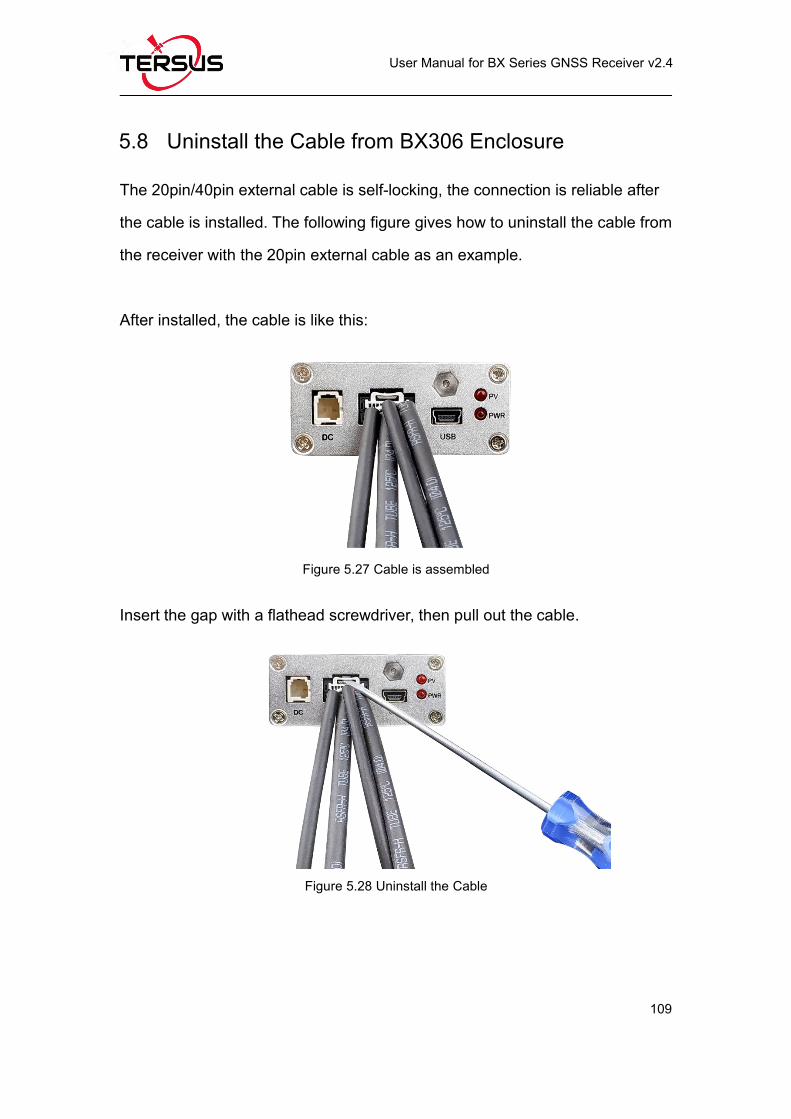
5.8 Uninstall the Cable from BX306 Enclosure..........................................109
6. Terminology...................................................................................................... 110
Page 7
User Manual for BX Series GNSS Receiver v2.4
VI
List of Figures
Figure 1.1 Overview of BX306 Board...................................................................... 5
Figure 1.2 The other side of BX306 Board..............................................................6
Figure 1.3 Overview of BX306Z Board....................................................................7
Figure 1.4 The other side of BX306Z Board...........................................................8
Figure 1.5 Overview of BX316 Board...................................................................... 9
Figure 1.6 The other side of BX316 Board........................................................... 10
Figure 1.7 Overview of BX316R Board..................................................................11
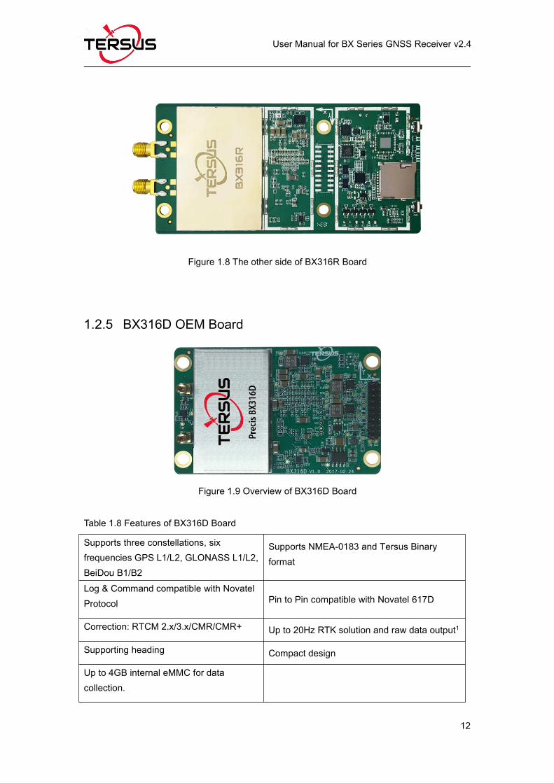
Figure 1.8 The other side of BX316R Board........................................................ 12
Figure 1.9 Overview of BX316D Board................................................................. 12
Figure 1.10 The other side of BX316D Board...................................................... 13
Figure 1.11 Overview of BX306 Enclosure...........................................................14
Figure 1.12 BX306 Enclosure Panel......................................................................15
Figure 1.13 Overview of BX316 Enclosure...........................................................15
Figure 1.14 BX316 Enclosure Panel......................................................................16
Figure 1.15 Overview of BX316R Enclosure........................................................18
Figure 1.16 Overview of BX316D Enclosure........................................................19
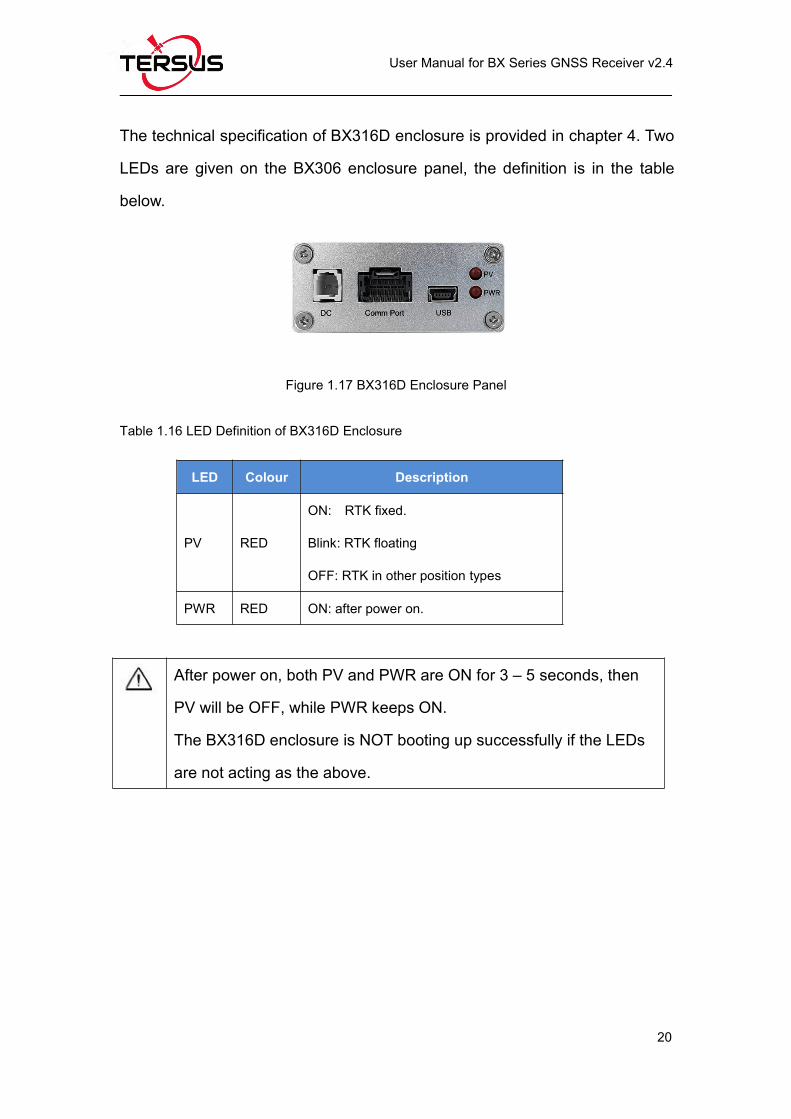
Figure 1.17 BX316D Enclosure Panel...................................................................20
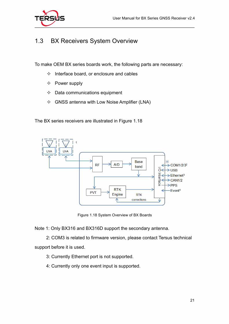
Figure 1.18 System Overview of BX Boards........................................................ 21
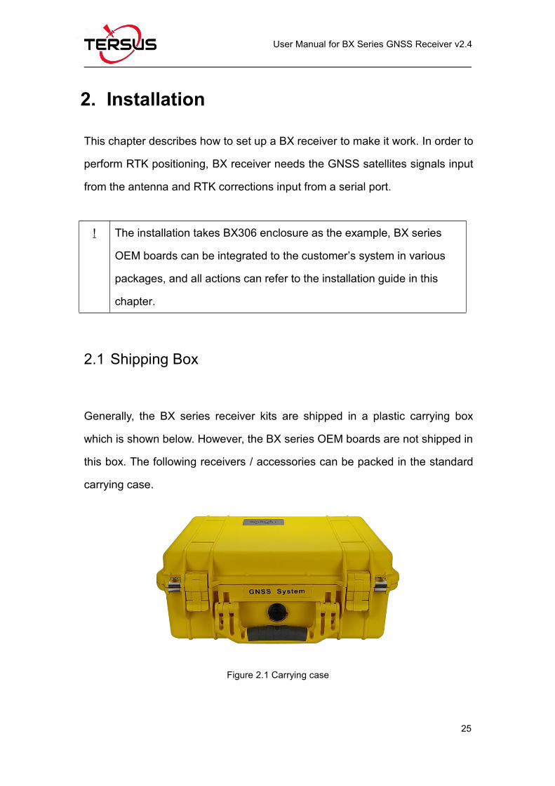
Figure 2.1 Carrying case..........................................................................................25
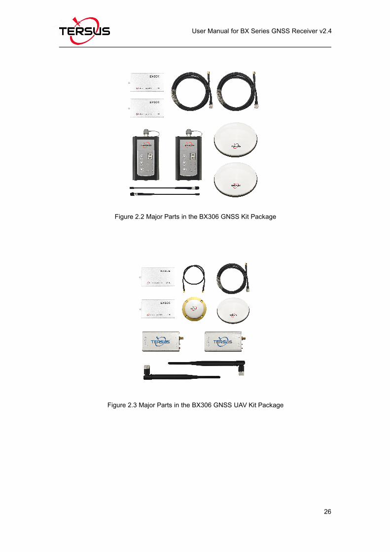
Figure 2.2 Major Parts in the BX306 GNSS Kit Package...................................26
Figure 2.3 Major Parts in the BX306 GNSS UAV Kit Package..........................26
Figure 2.4 UART to USB converter........................................................................27
Figure 2.5 Device Manager.....................................................................................28
Figure 2.6 AX3702 GNSS antenna........................................................................28
Figure 2.7 AX3703 GNSS Aviation Antenna.........................................................29
Page 8
User Manual for BX Series GNSS Receiver v2.4
VII
Figure 2.8 AX3705 Helix Antenna.......................................................................... 29
Figure 2.9 Config Page of Tersus GNSS Center................................................. 32
Figure 2.10 BX316D Enclosure connected to a Laptop..................................... 33
Figure 2.11 Main Windows of Tersus GNSS Center........................................... 34
Figure 2.12 Auto Base Station List interface........................................................ 35
Figure 2.13 Fixed position for base station...........................................................36
Figure 2.14 Base/Rover Configure.........................................................................36
Figure 2.15 Configure BX316D via Bluetooth...................................................... 39
Figure 2.16 Configure BX316D via PC..................................................................39
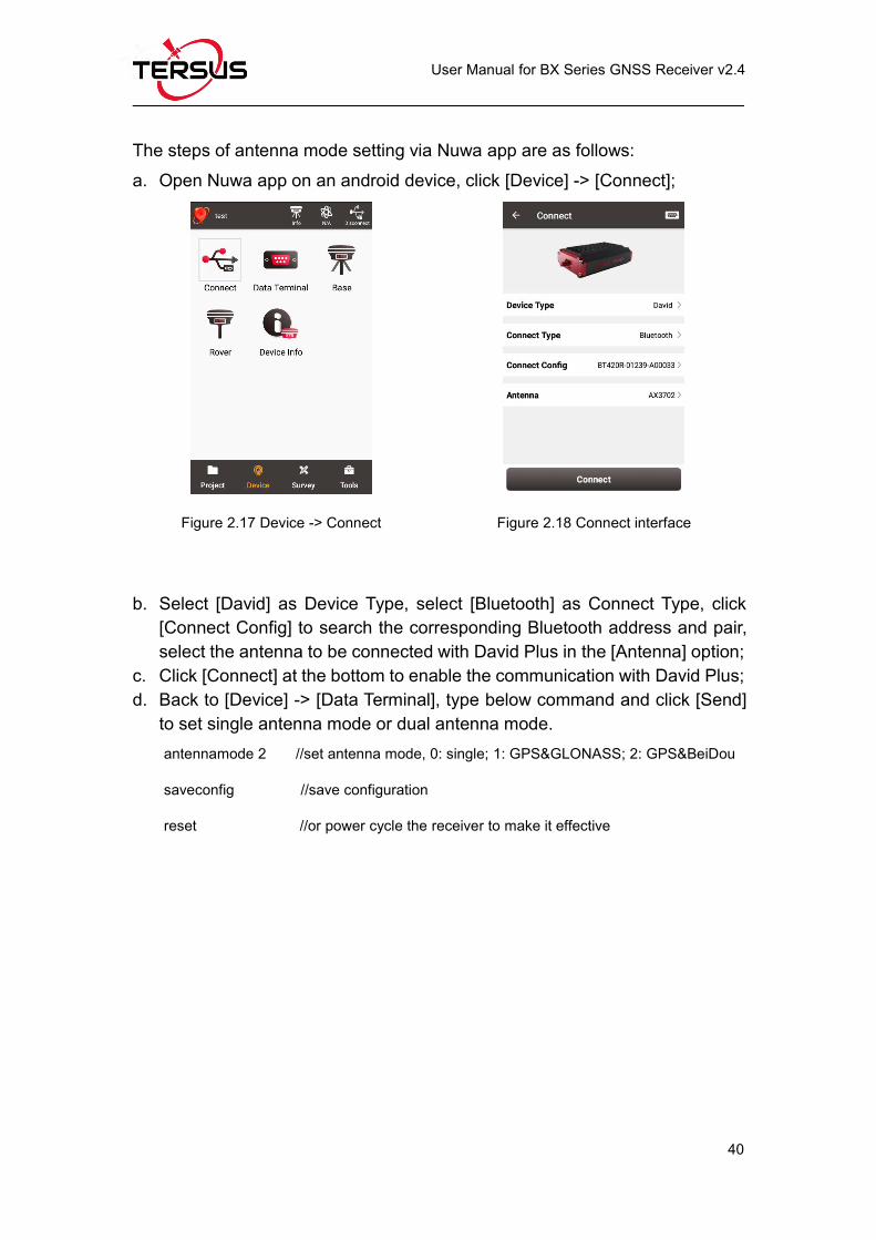
Figure 2.17 Device -> Connect...............................................................................40
Figure 2.18 Connect interface.................................................................................40
Figure 2.19 Set antenna mode 1............................................................................41
Figure 2.20 Set antenna mode 2............................................................................41
Figure 2.21 Save configuration...............................................................................41
Figure 2.22 Reset the receiver................................................................................41
Figure 2.23 Config window......................................................................................42
Figure 2.24 Set antenna mode to GPS & GLONASS.........................................43
Figure 2.25 Set antenna mode to GPS & BeiDou............................................... 43
Figure 2.26 Save configuration...............................................................................44
Figure 2.27 Reset the receiver................................................................................44
Figure 3.1 Main interface of Tersus GNSS Center.............................................. 47
Figure 3.2 Stop button on Tersus GNSS Center..................................................48
Figure 3.3 Find UpdateFirmware in Tools bar...................................................... 48
Figure 3.4 Select file to update...............................................................................49
Figure 3.5 Update in progress................................................................................ 49
Figure 3.6 Firmware update successful................................................................ 50
Figure 3.7 Advance setting for firmware update.................................................. 51
Page 9
User Manual for BX Series GNSS Receiver v2.4
VIII
Figure 3.8 Advance Update Setting....................................................................... 51
Figure 4.1 Connector J3 on BX306 board............................................................ 56
Figure 4.2 3.3V Reference Schematic...................................................................58
Figure 4.3 5V Reference Schematic......................................................................58
Figure 4.4 Reference Schematic for a Serial Port...............................................58
Figure 4.5 Reference Schematic for USB.............................................................59
Figure 4.6 Connectors J20 and J21 of BX306Z...................................................62
Figure 4.7 Outline of the 40pin external cable......................................................69
Figure 4.8 Connector J3 of BX316D......................................................................75
Figure 4.9 Outline of the 20pin external cable......................................................79
Figure 5.1 Download Files from eMMC Card with a Serial Port........................92
Figure 5.2 Download Files from eMMC Card with an USB Port........................92
Figure 5.3 5pin to USB Type A male cable...........................................................93
Figure 5.4 File download using Tersus Download...............................................93
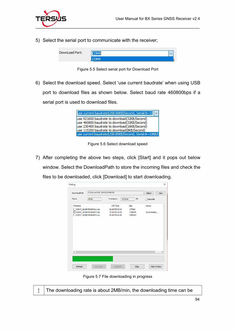
Figure 5.5 Select serial port for Download Port................................................... 94
Figure 5.6 Select download speed.........................................................................94
Figure 5.7 File downloading in progress............................................................... 94
Figure 5.8 BT120 and the cable............................................................................. 95
Figure 5.9 Outline of BX306 Connected to BT120..............................................95
Figure 5.10 Click Settings in NTRIP Client app................................................... 96
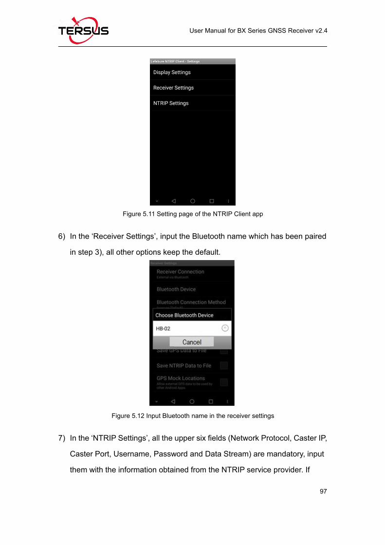
Figure 5.11 Setting page of the NTRIP Client app...............................................97
Figure 5.12 Input Bluetooth name in the receiver settings.................................97
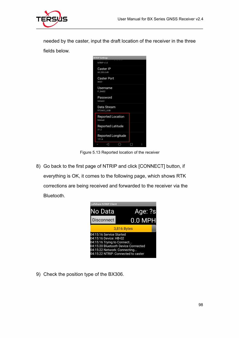
Figure 5.13 Reported location of the receiver......................................................98
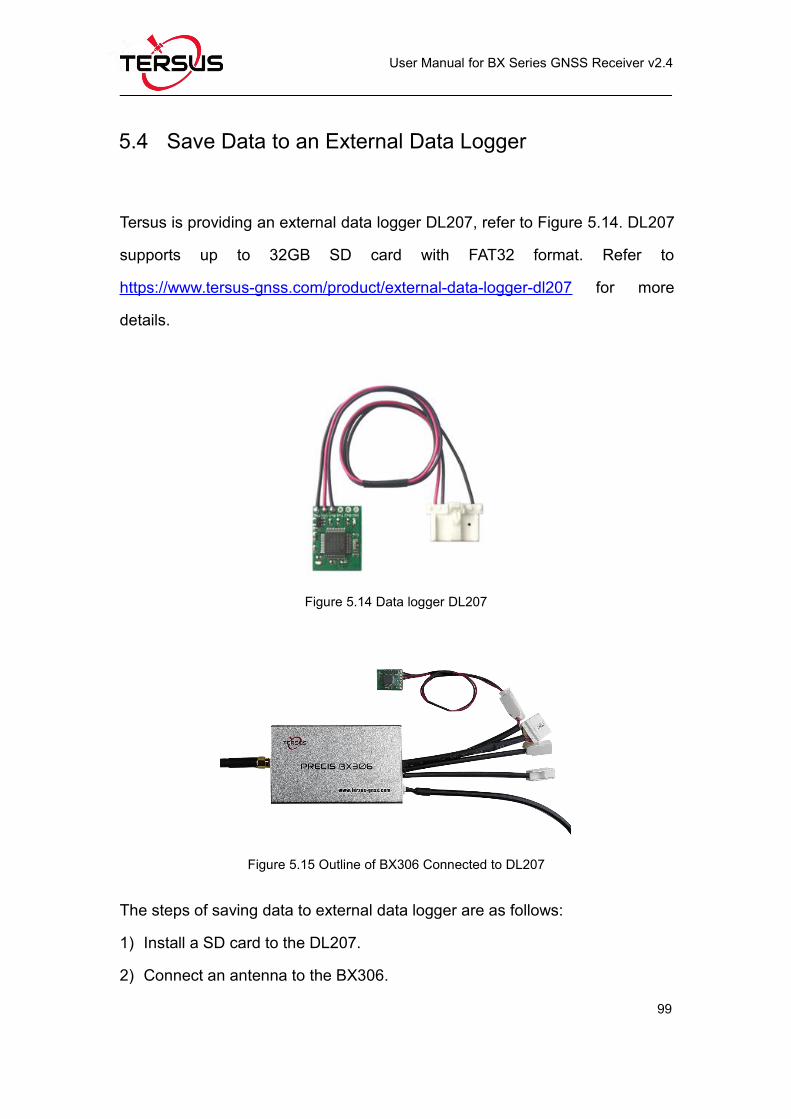
Figure 5.14 Data logger DL207.............................................................................. 99
Figure 5.15 Outline of BX306 Connected to DL207............................................99
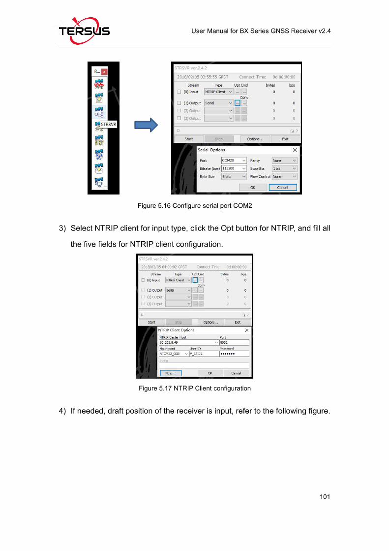
Figure 5.16 Configure serial port COM2.............................................................101
Figure 5.17 NTRIP Client configuration.............................................................. 101
Page 10
User Manual for BX Series GNSS Receiver v2.4
IX
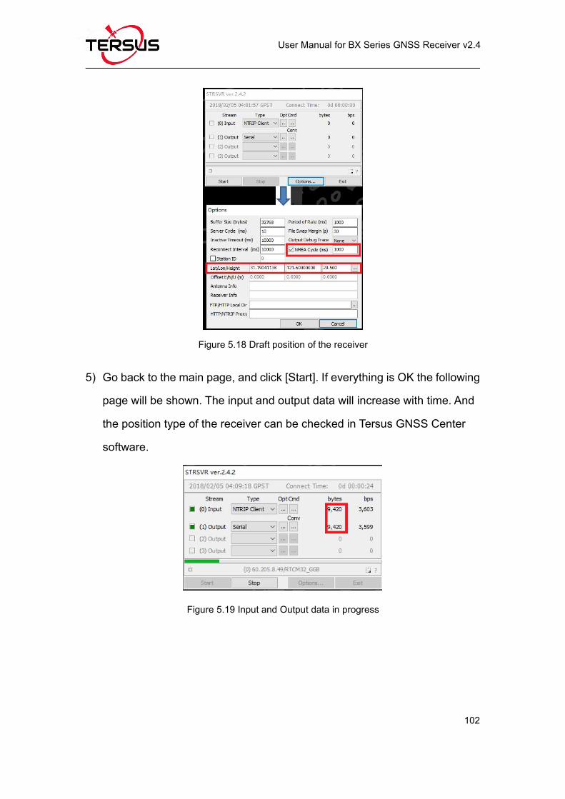
Figure 5.18 Draft position of the receiver............................................................102
Figure 5.19 Input and Output data in progress.................................................. 102
Figure 5.20 Transfer Cable....................................................................................103
Figure 5.21 Outline of BX306 Connected to RS460 Radio..............................104
Figure 5.22 Cable between Pixhawk and BX306.............................................. 105
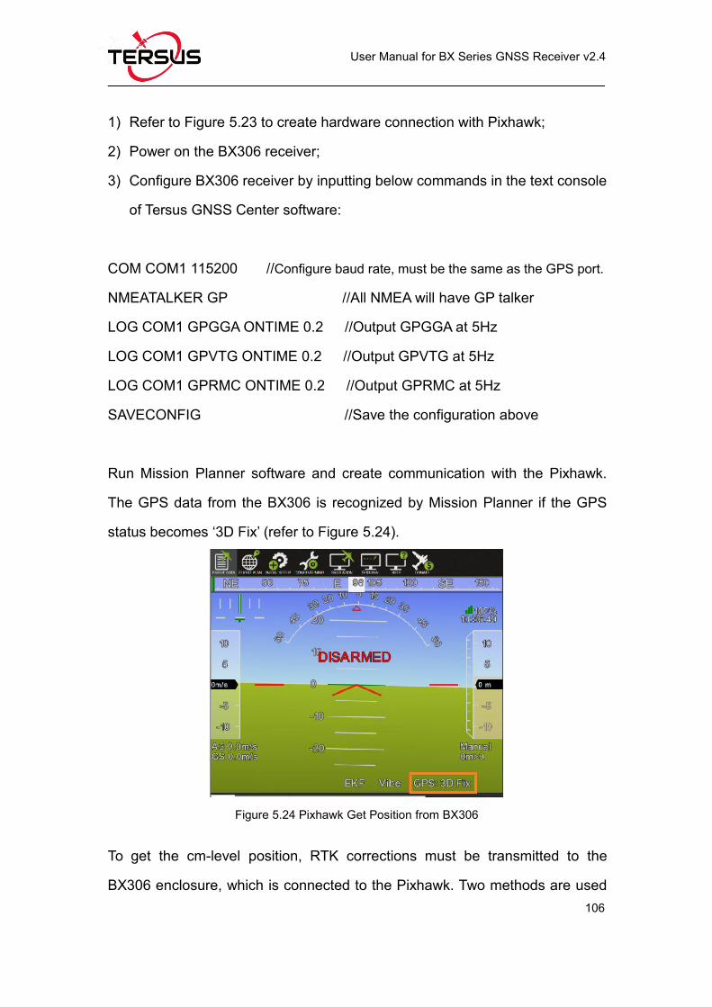
Figure 5.23 Outline of BX306 connected to Pixhawk....................................... 105
Figure 5.24 Pixhawk Get Position from BX306..................................................106
Figure 5.25 RTK corrections from the base BX306 are received................... 108
Figure 5.26 GPS status changes to rtk Fixed.................................................... 108
Figure 5.27 Cable is assembled...........................................................................109
Figure 5.28 Uninstall the Cable............................................................................ 109
Page 11
User Manual for BX Series GNSS Receiver v2.4
X
List of Tables
Table 0.1 Document / Software used in this User Manual....................................3
Table 1.1 Features of BX306 Board.........................................................................5
Table 1.2 LED Definition of BX306 board................................................................6
Table 1.3 Features of BX306Z Board...................................................................... 7
Table 1.4 LED Definition of BX306Z Board............................................................ 8
Table 1.5 Features of BX316 Board.........................................................................9
Table 1.6 LED Definition of BX316 Board.............................................................10
Table 1.7 Features of BX316R Board....................................................................11
Table 1.8 Features of BX316D Board....................................................................12
Table 1.9 LED Definition of BX316D Board..........................................................13
Table 1.10 Features of BX306 Enclosure..............................................................14
Table 1.11 LED Definition of BX306 Enclosure................................................... 15
Table 1.12 Features of BX316 Enclosure..............................................................16
Table 1.13 LEDs on BX316 Enclosure Panel.......................................................17
Table 1.14 Features of BX316R Enclosure...........................................................18
Table 1.15 Features of BX316D Enclosure...........................................................19
Table 1.16 LED Definition of BX316D Enclosure................................................ 20
Table 2.1 Input Power Requirements.....................................................................30
Table 2.2 Definition of the lights on Tersus GNSS Center..................................33
Table 4.1 BX306 Board Specifications.................................................................. 53
Table 4.2 Interface Signals Definition.................................................................... 56
Table 4.3 BX306Z Board Specifications................................................................59
Table 4.4 2X12 Header Signals Definition............................................................ 63
Table 4.5 2x3 Header Signals Definition............................................................... 65
Page 12
User Manual for BX Series GNSS Receiver v2.4
XI
Table 4.6 BX316 Board Performance.................................................................... 66
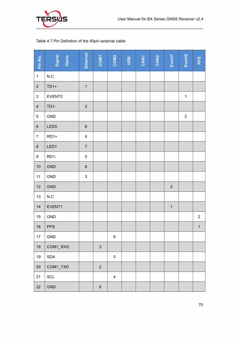
Table 4.7 Pin Definition of the 40pin external cable............................................ 70
Table 4.8 BX306D Board Specifications................................................................72
Table 4.9 Interface Signals Definition.................................................................... 75
Table 4.10 BX306 Enclosure Specifications.........................................................77
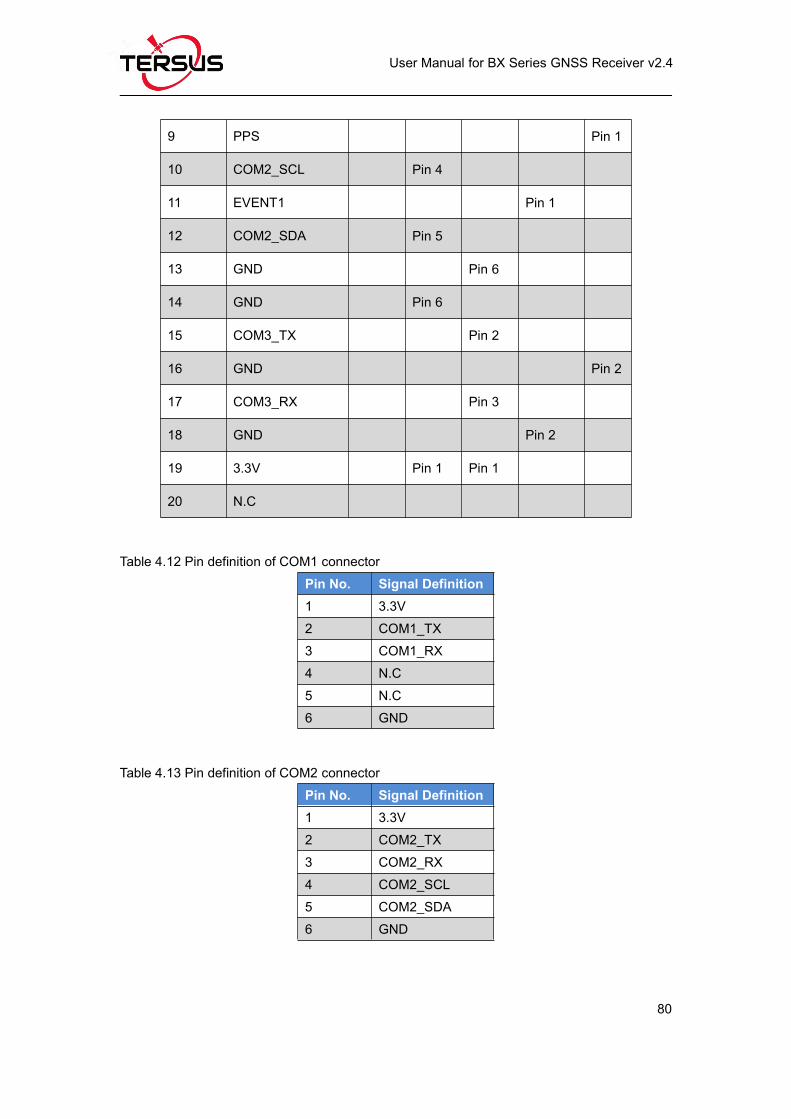
Table 4.11 Pin Definition of the 20pin external cable.......................................... 79
Table 4.12 Pin definition of COM1 connector.......................................................80
Table 4.13 Pin definition of COM2 connector.......................................................80
Table 4.14 Pin definition of COM3 connector.......................................................81
Table 4.15 Pin definition of EVENT connector..................................................... 81
Table 4.16 Pin definition of PPS connector...........................................................81
Table 4.17 BX316 Enclosure Specifications.........................................................81
Table 4.18 BX316R Enclosure Specifications......................................................84
Table 4.19 BX316D Enclosure Specifications......................................................86
Page 13
User Manual for BX Series GNSS Receiver v2.4
1
Notices
FCC Notices
The BX306 enclosure has been tested and found to comply with the radiated
and conducted emission limits for a Class A digital device. The Class A limits
are designed to provide reasonable protection against harmful interference in
a residential installation.
The BX316D enclosure has been tested and found to comply with the radiated
and conducted emission limits for a Class A digital device. The Class A limits
are designed to provide reasonable protection against harmful interference in
a residential installation.
CE Marking
Tersus GNSS Inc. declares that BX306 enclosure and BX316D enclosure are
in compliance with the essential requirements (radio performance,
electromagnetic compatibility and electrical safety) and other relevant
provisions of Directive 1999/5/EC, EMC Directive 2004/108/EC, and the RoHS
Recast Directive 2011/65/EU. Therefore the equipment is labeled with the
following CE-marking.
The Declaration of Conformity may be obtained from Tersus GNSS Inc.
Page 14
User Manual for BX Series GNSS Receiver v2.4
2
The following notices apply to all Tersus BX series receivers.
Changes or modifications to this equipment not expressly approved
by Tersus could void the user’s authority to operate this equipment or
even has risk to damage the receivers.
ConventionsThe following conventions are used in this manual:
! Information that supplements or clarifies text.
A caution that actions, operation or configuration may lead to incorrect
or improper use of the hardware.
Tersus is providing BX series GNSS receivers with OEM version as well as
with enclosure in a metal case. When a board is mentioned, it is OEM version
of the receiver, specifically. When enclosure is mentioned, it is receiver version
in a metal case, specifically.
In this manual, all the commands to a receiver are in capital letters, which is
just for easy identification, the commands are not case-sensitive.
A warning that actions, operation or configuration may result in
regulatory noncompliance, safety issues or equipment damage.
Page 15
User Manual for BX Series GNSS Receiver v2.4
3
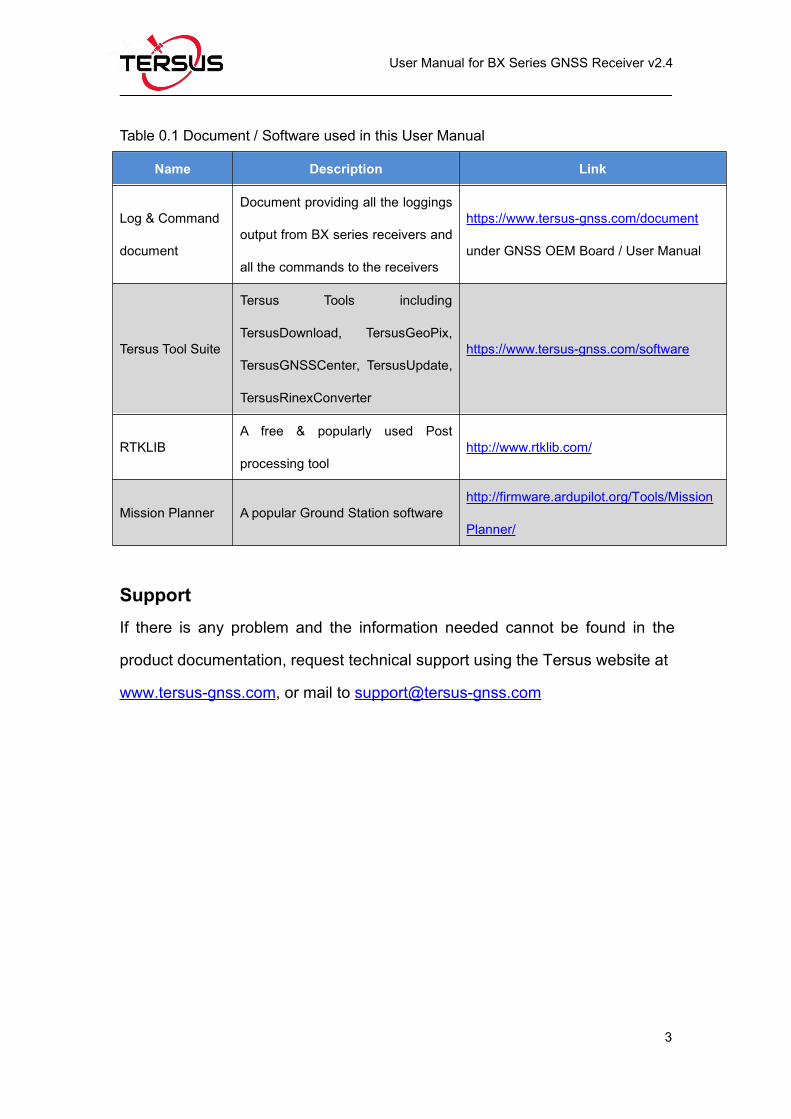
Table 0.1 Document / Software used in this User Manual
Name Description Link
Log & Command
document
Document providing all the loggings
output from BX series receivers and
all the commands to the receivers
https://www.tersus-gnss.com/document
under GNSS OEM Board / User Manual
Tersus Tool Suite
Tersus Tools including
TersusDownload, TersusGeoPix,
TersusGNSSCenter, TersusUpdate,
TersusRinexConverter
https://www.tersus-gnss.com/software
RTKLIBA free & popularly used Post
processing toolhttp://www.rtklib.com/
Mission Planner A popular Ground Station softwarehttp://firmware.ardupilot.org/Tools/Mission
Planner/
SupportIf there is any problem and the information needed cannot be found in the
product documentation, request technical support using the Tersus website at
www.tersus-gnss.com, or mail to [email protected]
Page 16
User Manual for BX Series GNSS Receiver v2.4
4
1. Introduction
1.1 Overview of BX Series GNSS Receivers
BX series GNSS receivers are cost-efficient GNSS RTK board for cm-level
positioning, which can be used for real-time RTK positioning as well as raw
data collection for post-processing application. BX receivers support existed
and planned GPS, BeiDou and GLONASS signals. Both OEM boards and the
enclosures are designed for the flexibility of integration and configuration. BX
series receivers are delivered with OEM boards as well as in enclosures.
1.1.1 BX GNSS OEM Boards
BX306 OEM board – refer to section 1.2.1 for details;
BX306Z OEM board – refer to section 1.2.2 for details;
BX316 OEM board (EOL, replaced by BX316D OEM board) – refer to
section 1.2.3 for details;
BX316R OEM board (EOL, replaced by BX306 OEM board) – refer to
section 1.2.4 for details;
BX316D OEM board – refer to section 1.2.5 for details;
1.1.2 BX GNSS Enclosures
BX306 enclosure – refer to section 1.2.6 for details;
BX316 enclosure (EOL, replaced by BX316D enclosure) – refer to section
1.2.7 for details;
BX316R enclosure (EOL, replaced by BX306 enclosure) – refer to section
1.2.8 for details;
BX316D enclosure – refer to section 1.2.9 for details.
Page 17
User Manual for BX Series GNSS Receiver v2.4
5
1.2 Related documents and information
1.2.1 BX306 OEM Board
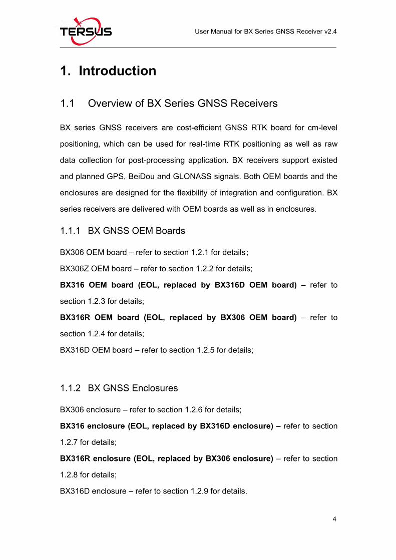
Figure 1.1 Overview of BX306 Board
Table 1.1 Features of BX306 Board
Supports three constellations, sixfrequencies: GPS L1/L2, GLONASSL1/L2, BeiDou B1/B2
Supports NMEA-0183 and Tersus Binaryformat
Log & Command compatible with NovatelProtocol Pin to Pin compatible with Novatel OEM615
Correction: RTCM 2.x/3.x/CMR/CMR+ Up to 20Hz RTK solution and raw data output1
Up to 4GB internal eMMC for datacollection. Compact design
Note 1: 20Hz solution is related to firmware release, contact Tersus technical
support before this solution is used.
The technical specification of BX306 board is provided in chapter 4. Two LEDs
are installed on the BX306 board, whose definition is given in Table 1.2:
Page 18
User Manual for BX Series GNSS Receiver v2.4
6
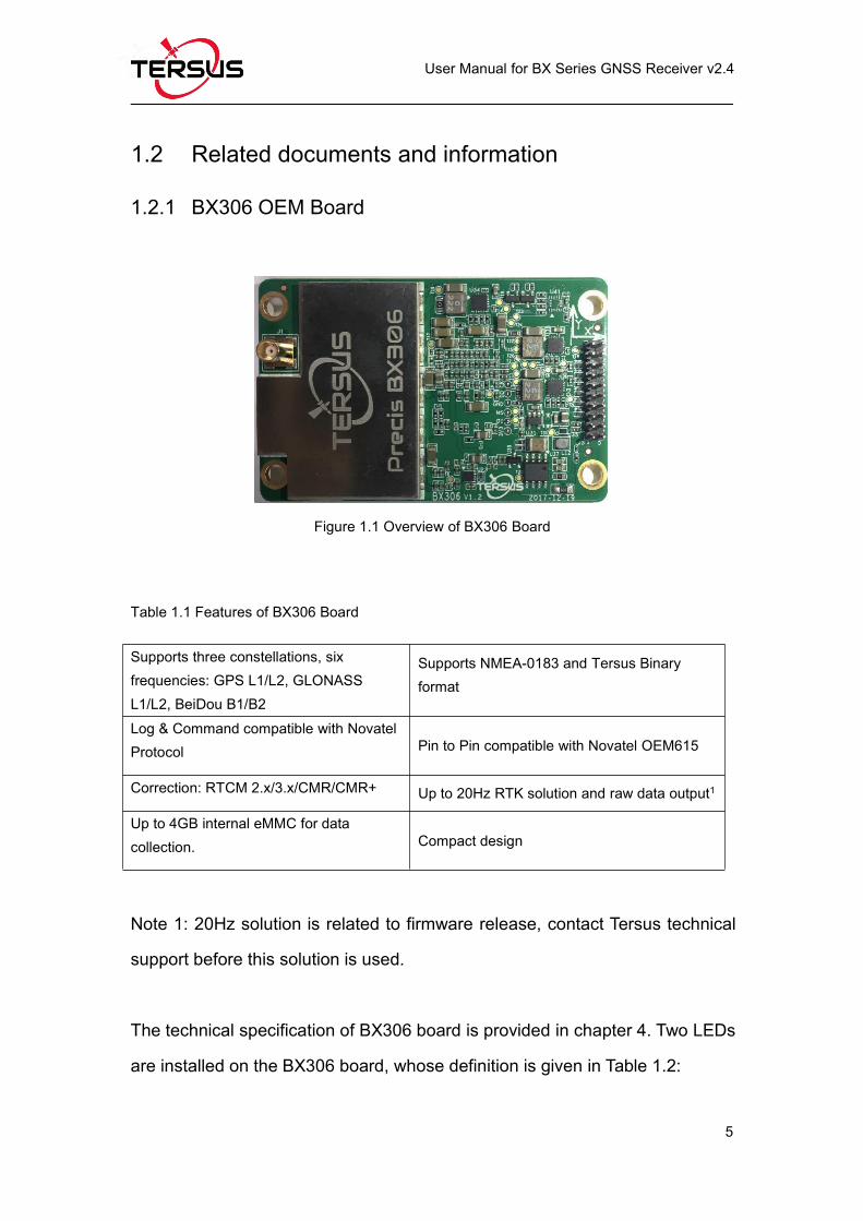
Figure 1.2 The other side of BX306 Board
Table 1.2 LED Definition of BX306 board
LED Colour Description
LED1 (left) ORANGEBlink 1Hz: if log is output at 1Hz or less.
Blink the same rate as the log if log output rate >1Hz.
LED2 (right) GREEN
ON: RTK fixed.
Blink: RTK float solution.
OFF: Other position types.
After power on, both LED1 and LED2 are ON for 3 – 5 seconds, then
both are OFF for 2 seconds. Afterwards, LED1 will blink at 1Hz.
The BX306 board is NOT booting up successfully if the LEDs are not
acting as the above.
Page 19
User Manual for BX Series GNSS Receiver v2.4
7
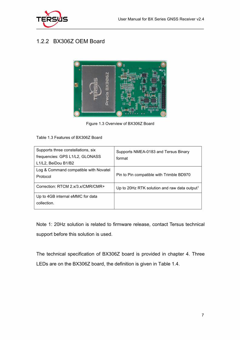
1.2.2 BX306Z OEM Board
Figure 1.3 Overview of BX306Z Board
Table 1.3 Features of BX306Z Board
Supports three constellations, sixfrequencies: GPS L1/L2, GLONASSL1/L2, BeiDou B1/B2
Supports NMEA-0183 and Tersus Binaryformat
Log & Command compatible with NovatelProtocol Pin to Pin compatible with Trimble BD970
Correction: RTCM 2.x/3.x/CMR/CMR+ Up to 20Hz RTK solution and raw data output1
Up to 4GB internal eMMC for datacollection.
Note 1: 20Hz solution is related to firmware release, contact Tersus technical
support before this solution is used.
The technical specification of BX306Z board is provided in chapter 4. Three
LEDs are on the BX306Z board, the definition is given in Table 1.4.
Page 20
User Manual for BX Series GNSS Receiver v2.4
8
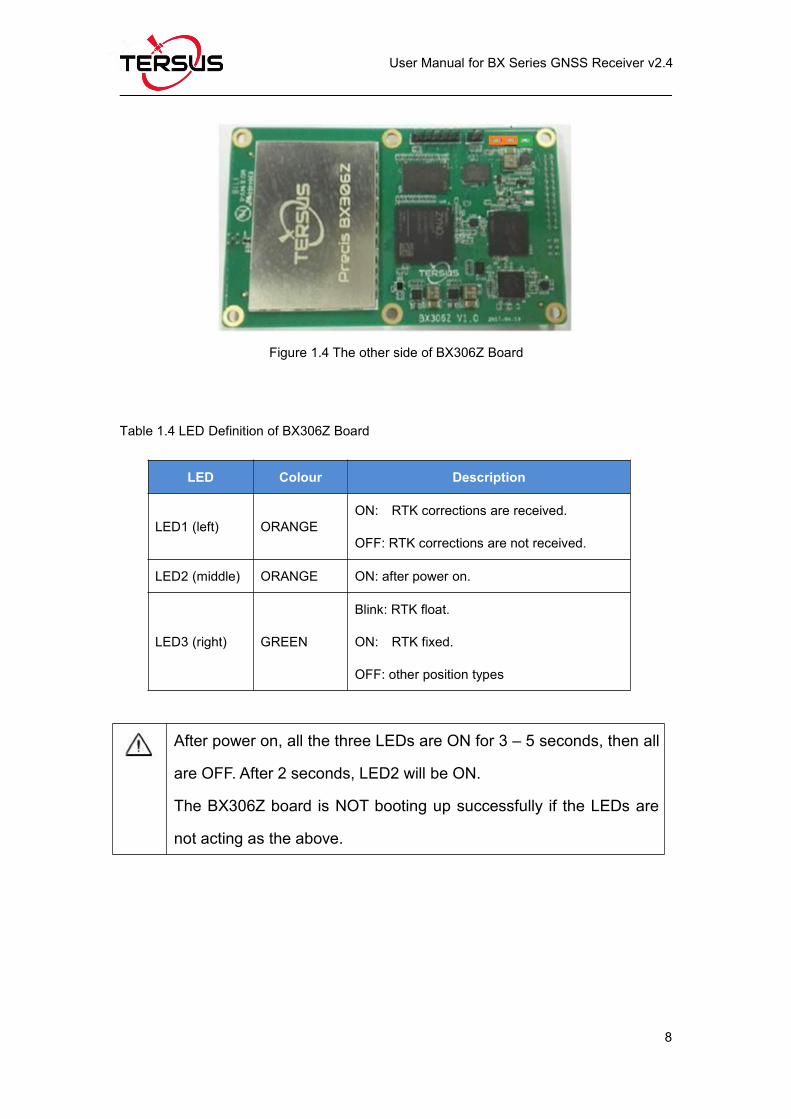
Figure 1.4 The other side of BX306Z Board
Table 1.4 LED Definition of BX306Z Board
LED Colour Description
LED1 (left) ORANGEON: RTK corrections are received.
OFF: RTK corrections are not received.
LED2 (middle) ORANGE ON: after power on.
LED3 (right) GREEN
Blink: RTK float.
ON: RTK fixed.
OFF: other position types
After power on, all the three LEDs are ON for 3 – 5 seconds, then all
are OFF. After 2 seconds, LED2 will be ON.
The BX306Z board is NOT booting up successfully if the LEDs are
not acting as the above.
Page 21
User Manual for BX Series GNSS Receiver v2.4
9
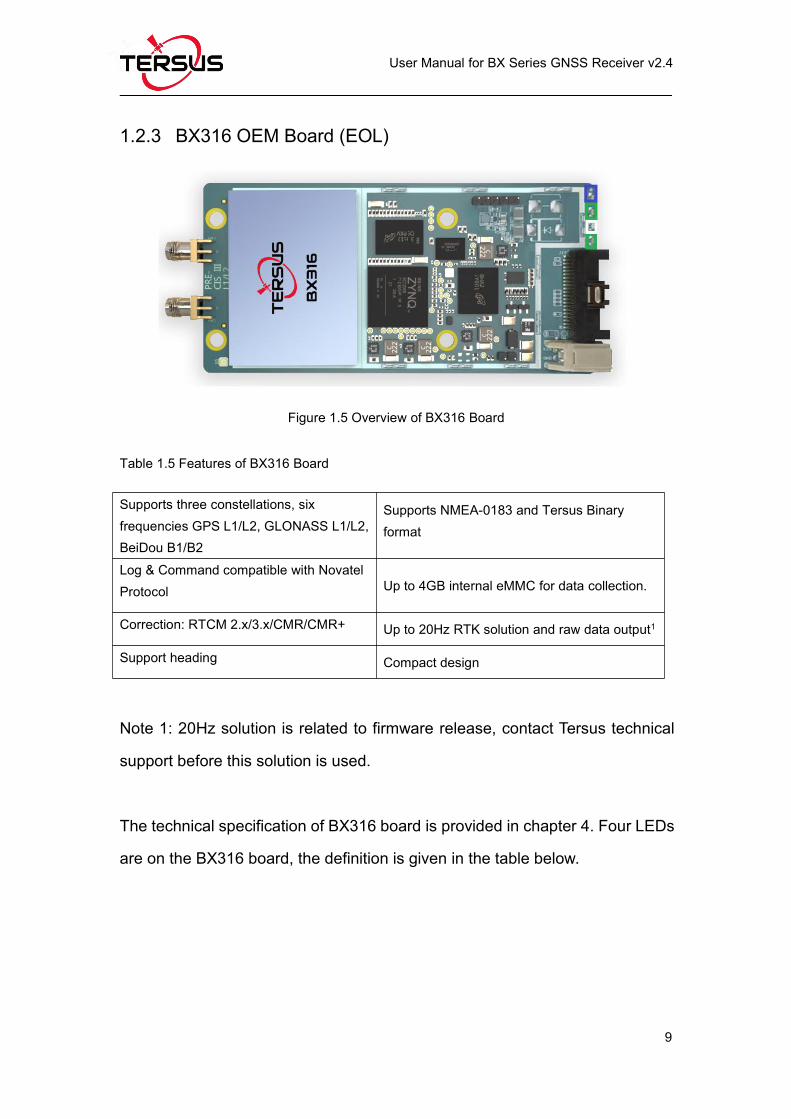
1.2.3 BX316 OEM Board (EOL)
Figure 1.5 Overview of BX316 Board
Table 1.5 Features of BX316 Board
Supports three constellations, sixfrequencies GPS L1/L2, GLONASS L1/L2,BeiDou B1/B2
Supports NMEA-0183 and Tersus Binaryformat
Log & Command compatible with NovatelProtocol Up to 4GB internal eMMC for data collection.
Correction: RTCM 2.x/3.x/CMR/CMR+ Up to 20Hz RTK solution and raw data output1
Support heading Compact design
Note 1: 20Hz solution is related to firmware release, contact Tersus technical
support before this solution is used.
The technical specification of BX316 board is provided in chapter 4. Four LEDs
are on the BX316 board, the definition is given in the table below.
Page 22
User Manual for BX Series GNSS Receiver v2.4
10
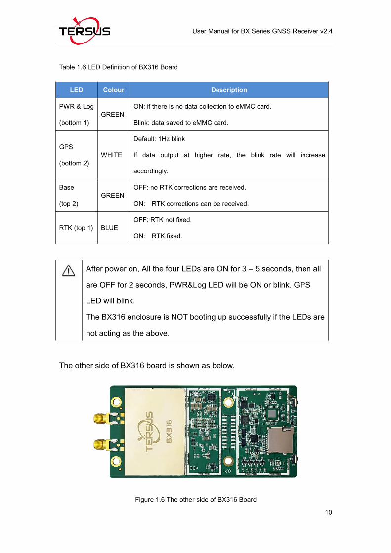
Table 1.6 LED Definition of BX316 Board
LED Colour Description
PWR & Log
(bottom 1)GREEN
ON: if there is no data collection to eMMC card.
Blink: data saved to eMMC card.
GPS
(bottom 2)WHITE
Default: 1Hz blink
If data output at higher rate, the blink rate will increase
accordingly.
Base
(top 2)GREEN
OFF: no RTK corrections are received.
ON: RTK corrections can be received.
RTK (top 1) BLUEOFF: RTK not fixed.
ON: RTK fixed.
After power on, All the four LEDs are ON for 3 – 5 seconds, then all
are OFF for 2 seconds, PWR&Log LED will be ON or blink. GPS
LED will blink.
The BX316 enclosure is NOT booting up successfully if the LEDs are
not acting as the above.
The other side of BX316 board is shown as below.
Figure 1.6 The other side of BX316 Board
Page 23
User Manual for BX Series GNSS Receiver v2.4
11
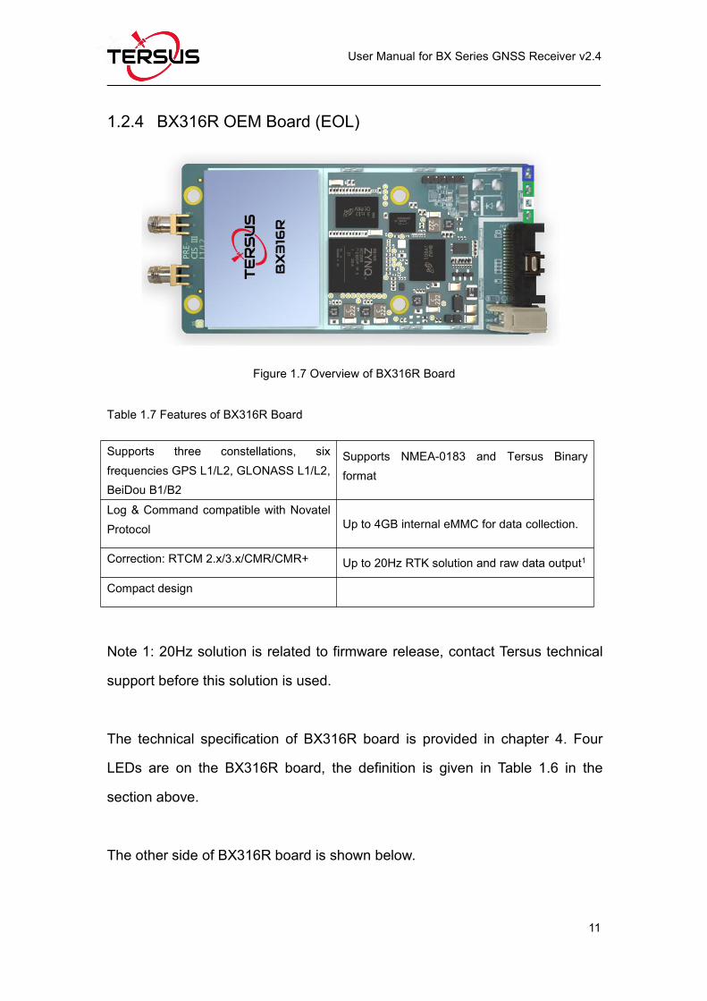
1.2.4 BX316R OEM Board (EOL)
Figure 1.7 Overview of BX316R Board
Table 1.7 Features of BX316R Board
Supports three constellations, sixfrequencies GPS L1/L2, GLONASS L1/L2,BeiDou B1/B2
Supports NMEA-0183 and Tersus Binaryformat
Log & Command compatible with NovatelProtocol Up to 4GB internal eMMC for data collection.
Correction: RTCM 2.x/3.x/CMR/CMR+ Up to 20Hz RTK solution and raw data output1
Compact design
Note 1: 20Hz solution is related to firmware release, contact Tersus technical
support before this solution is used.
The technical specification of BX316R board is provided in chapter 4. Four
LEDs are on the BX316R board, the definition is given in Table 1.6 in the
section above.
The other side of BX316R board is shown below.
Page 24
User Manual for BX Series GNSS Receiver v2.4
12
Figure 1.8 The other side of BX316R Board
1.2.5 BX316D OEM Board
Figure 1.9 Overview of BX316D Board
Table 1.8 Features of BX316D Board
Supports three constellations, sixfrequencies GPS L1/L2, GLONASS L1/L2,BeiDou B1/B2
Supports NMEA-0183 and Tersus Binaryformat
Log & Command compatible with NovatelProtocol Pin to Pin compatible with Novatel 617D
Correction: RTCM 2.x/3.x/CMR/CMR+ Up to 20Hz RTK solution and raw data output1
Supporting heading Compact design
Up to 4GB internal eMMC for datacollection.
Page 25
User Manual for BX Series GNSS Receiver v2.4
13
Note 1: 20Hz solution is related to firmware release, contact Tersus technical
support before this solution is used.
The technical specification of BX316D board is provided in chapter 4. Two
LEDs are installed on the BX316D board, whose definition is given in Table
1.9:
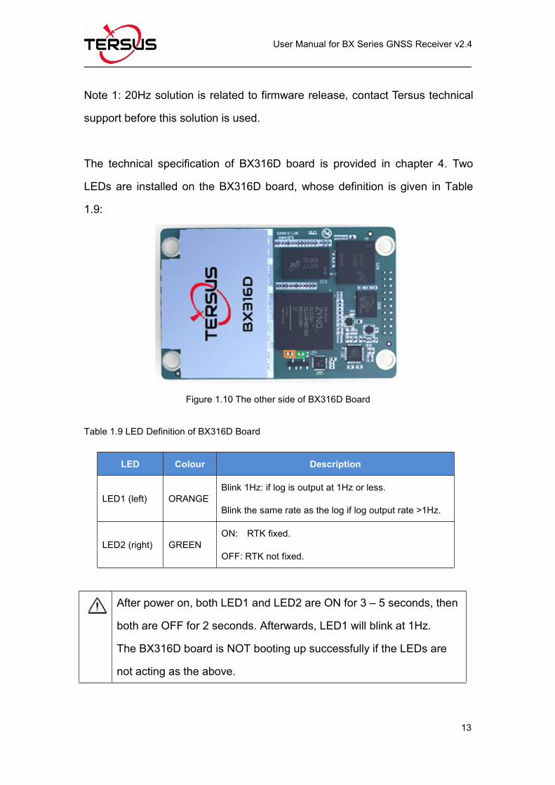
Figure 1.10 The other side of BX316D Board
Table 1.9 LED Definition of BX316D Board
LED Colour Description
LED1 (left) ORANGEBlink 1Hz: if log is output at 1Hz or less.
Blink the same rate as the log if log output rate >1Hz.
LED2 (right) GREENON: RTK fixed.
OFF: RTK not fixed.
After power on, both LED1 and LED2 are ON for 3 – 5 seconds, then
both are OFF for 2 seconds. Afterwards, LED1 will blink at 1Hz.
The BX316D board is NOT booting up successfully if the LEDs are
not acting as the above.
Page 26
User Manual for BX Series GNSS Receiver v2.4
14
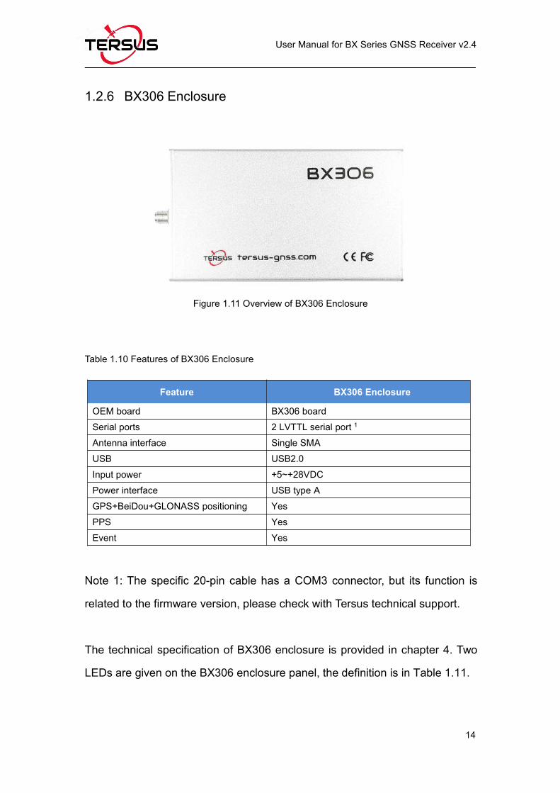
1.2.6 BX306 Enclosure
Figure 1.11 Overview of BX306 Enclosure
Table 1.10 Features of BX306 Enclosure
Feature BX306 Enclosure
OEM board BX306 boardSerial ports 2 LVTTL serial port 1
Antenna interface Single SMAUSB USB2.0Input power +5~+28VDCPower interface USB type AGPS+BeiDou+GLONASS positioning YesPPS YesEvent Yes
Note 1: The specific 20-pin cable has a COM3 connector, but its function is
related to the firmware version, please check with Tersus technical support.
The technical specification of BX306 enclosure is provided in chapter 4. Two
LEDs are given on the BX306 enclosure panel, the definition is in Table 1.11.
Page 27
User Manual for BX Series GNSS Receiver v2.4
15
Figure 1.12 BX306 Enclosure Panel
Table 1.11 LED Definition of BX306 Enclosure
LED Colour Description
LED1 REDON: RTK fixed.
OFF: RTK not fixed.
LED2 RED ON: after power on.
After power on, both LED1 and LED2 are ON for 3 – 5 seconds, then
LED1 will be OFF, while LED2 keeps ON.
The BX306 enclosure is NOT booting up successfully if the LEDs are
not acting as the above.
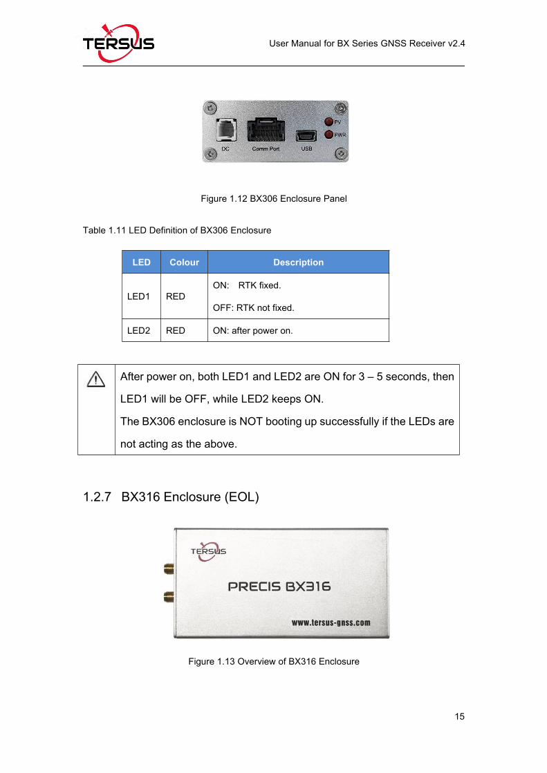
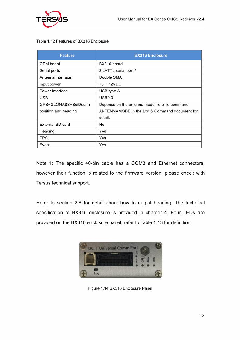
1.2.7 BX316 Enclosure (EOL)
Figure 1.13 Overview of BX316 Enclosure
Page 28
User Manual for BX Series GNSS Receiver v2.4
16
Table 1.12 Features of BX316 Enclosure
Feature BX316 Enclosure
OEM board BX316 boardSerial ports 2 LVTTL serial port 1
Antenna interface Double SMAInput power +5~+12VDCPower interface USB type AUSB USB2.0GPS+GLONASS+BeiDou inposition and heading
Depends on the antenna mode, refer to commandANTENNAMODE in the Log & Command document fordetail.
External SD card NoHeading YesPPS YesEvent Yes
Note 1: The specific 40-pin cable has a COM3 and Ethernet connectors,
however their function is related to the firmware version, please check with
Tersus technical support.
Refer to section 2.8 for detail about how to output heading. The technical
specification of BX316 enclosure is provided in chapter 4. Four LEDs are
provided on the BX316 enclosure panel, refer to Table 1.13 for definition.
Figure 1.14 BX316 Enclosure Panel
Page 29
User Manual for BX Series GNSS Receiver v2.4
17
Table 1.13 LEDs on BX316 Enclosure Panel
LED Colour Description
PWR &
LogGREEN
ON: if there is no data collection to eMMC card.
Blink: data saved to eMMC card.
GPS WHITEDefault: 1Hz blink
If data output at higher rate, the blink rate will increase accordingly.
Base GREENOFF: no RTK corrections are received.
ON: RTK corrections can be received.
RTK BLUEOFF: RTK not fixed.
ON: RTK fixed.
After power on, All the four LEDs are ON for 3 – 5 seconds, then all
are OFF for 2 seconds, PWR&Log LED will be ON or blink. GPS
LED will blink.
The BX316 enclosure is NOT booting up successfully if the LEDs are
not acting as the above.
1.2.8 BX316R Enclosure (EOL)
BX316R enclosure is designed specifically for post processing applications,
such as mobile mapping or monitoring system. It has the same hardware as
that of BX316, however it cannot support RTK positioning or heading.
! BX316R can support RTK positioning and heading after an auth code
is input. Contact Tersus sales for more details.
Page 30
User Manual for BX Series GNSS Receiver v2.4
18
Figure 1.15 Overview of BX316R Enclosure
Table 1.14 Features of BX316R Enclosure
Feature BX316R Enclosure
OEM board BX316R boardSerial ports 2 LVTTL serial port 1
Antenna interface Two SMA connectors2
Input power +5~+12VDCPower interface USB type AUSB USB2.0GPS+GLONASS+BeiDou in position YesExternal SD card NoHeading NoPPS YesEvent Yes
Note 1: The specific 40-pin cable has a COM3 connector, but its function is
related to the firmware version.
Note 2: Only P-ANT interface can work.
The technical specification of BX316R enclosure is provided in chapter 4.
BX316R enclosure has the same LEDs on panel as BX316 enclosure, and has
the same the booting up mode as BX316 enclosure. Refer to section 1.2.7 for
the LEDs definition of BX316R.
Page 31
User Manual for BX Series GNSS Receiver v2.4
19
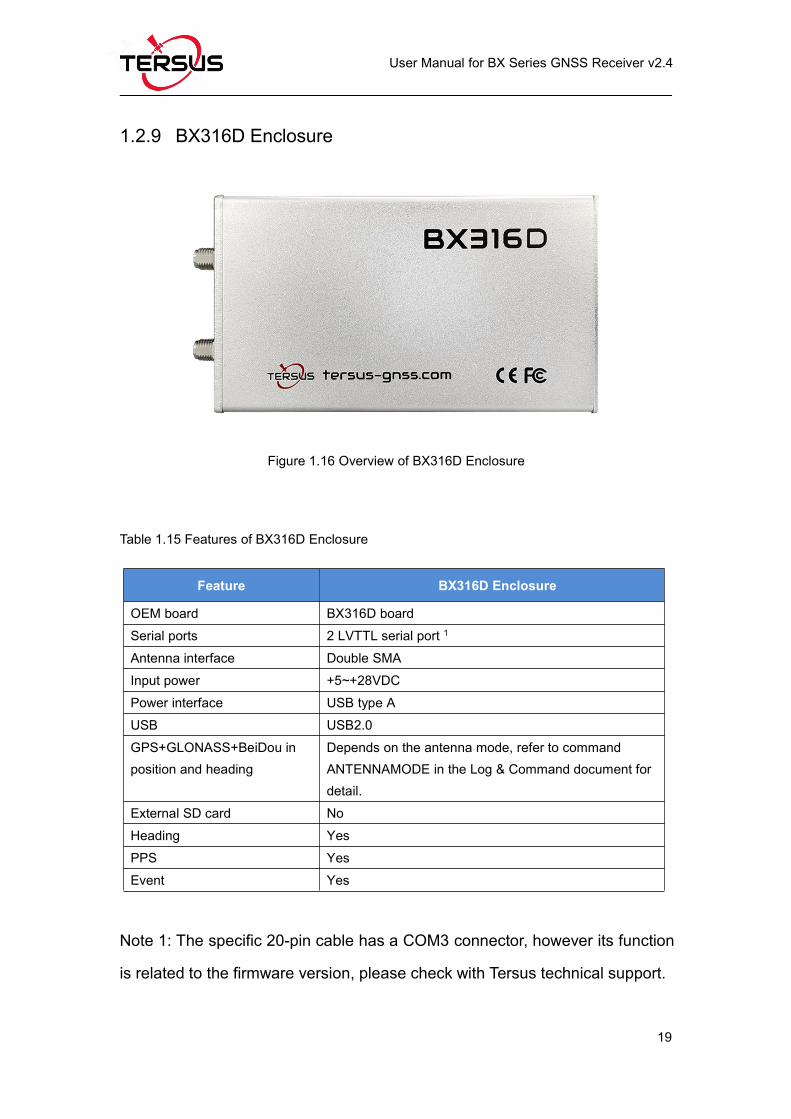
1.2.9 BX316D Enclosure
Figure 1.16 Overview of BX316D Enclosure
Table 1.15 Features of BX316D Enclosure
Feature BX316D Enclosure
OEM board BX316D boardSerial ports 2 LVTTL serial port 1
Antenna interface Double SMAInput power +5~+28VDCPower interface USB type AUSB USB2.0GPS+GLONASS+BeiDou inposition and heading
Depends on the antenna mode, refer to commandANTENNAMODE in the Log & Command document fordetail.
External SD card NoHeading YesPPS YesEvent Yes
Note 1: The specific 20-pin cable has a COM3 connector, however its function
is related to the firmware version, please check with Tersus technical support.
Page 32
User Manual for BX Series GNSS Receiver v2.4
20
The technical specification of BX316D enclosure is provided in chapter 4. Two
LEDs are given on the BX306 enclosure panel, the definition is in the table
below.
Figure 1.17 BX316D Enclosure Panel
Table 1.16 LED Definition of BX316D Enclosure
LED Colour Description
PV RED
ON: RTK fixed.
Blink: RTK floating
OFF: RTK in other position types
PWR RED ON: after power on.
After power on, both PV and PWR are ON for 3 – 5 seconds, then
PV will be OFF, while PWR keeps ON.
The BX316D enclosure is NOT booting up successfully if the LEDs
are not acting as the above.
Page 33
User Manual for BX Series GNSS Receiver v2.4
21
1.3 BX Receivers System Overview
To make OEM BX series boards work, the following parts are necessary:
Interface board, or enclosure and cables
Power supply
Data communications equipment
GNSS antenna with Low Noise Amplifier (LNA)
The BX series receivers are illustrated in Figure 1.18
Figure 1.18 System Overview of BX Boards
Note 1: Only BX316 and BX316D support the secondary antenna.
2: COM3 is related to firmware version, please contact Tersus technical
support before it is used.
3: Currently Ethernet port is not supported.
4: Currently only one event input is supported.
Page 34
User Manual for BX Series GNSS Receiver v2.4
22
1.3.1 BX Series OEM Boards
BX series OEM boards consist of a Radio Frequency (RF) section and a digital
section.
Radio Frequency (RF) Section
The receiver obtains filtered, amplified GNSS signals from the antenna. The
RF section down converts the incoming RF signals to Intermediate Frequency
(IF) signals which are processed by the digital section. The RF section also
supplies power to the active antenna LNA through the coaxial cable. The RF
section has been designed to reject common sources of interference.
Digital Section
The core of the digital section is the base band, which is realized with a FPGA
chip. The digital section digitizes and processes the base band signals to
obtain a PVT (Position, Velocity and Time) solution. If RTK corrections from
the base are received, the receiver will output cm-level position. The digital
section also processes the system I/O, shown in Figure 1.18.
1.3.2 BX Enclosures
An enclosure is necessary to protect the OEM BX series boards from
environmental extremes and high levels RF interference, and it brings
convenience for the customers to use the receivers.
Page 35
User Manual for BX Series GNSS Receiver v2.4
23
1.3.3 Antenna
The antenna converts electromagnetic signals transmitted by GNSS satellites
into electrical signals that can be used by the receiver.
An active GNSS antenna is required for optimal receiver performance. Tersus
is providing active GNSS antennas with precise phase centers and robust
enclosures (refer to https://www.tersus-gnss.com/product/accessories for
more about antennas.
1.3.4 Power Supply
A power supply capable of delivering the minimum receiver operating voltage
and power is required. Refer to section 2.4 for details.
1.3.5 Communication Equipment
A computer, a tablet or other data communications device are necessary to
communicate with the receiver, and to receive and store the data that the
receiver outputs.
1.3.6 Internal eMMC Card/External SD Card
! All the BX receivers support up to 4GB internal eMMC card by
FW0020 or later firmware.
Page 36
User Manual for BX Series GNSS Receiver v2.4
24
! The external SD card must meet:
Size ≤ 16GB
File system: FAT32
The SD card should be installed into the external data logger before it
is used, refer to section 0 for details.
The data can be saved on the internal eMMC or external SD card manually or
automatically, which is determined by the command LOGFILE.
1.3.7 Enable Heading
! Only OEM BX316D board/enclosure and BX316 board/enclosure can
support heading output.
The default configuration of BX316D and BX316 is in single antenna mode, in
which heading output is not supported. Heading output is supported only when
they are in dual antenna mode. Command ANTENNAMODE must be input to
select the antenna mode, refer to chapter 2.8 Heading Output for details.
! When in single antenna mode, the connector for the secondary
antenna connector can be left floating.
Page 37
User Manual for BX Series GNSS Receiver v2.4
25
2. Installation
This chapter describes how to set up a BX receiver to make it work. In order to
perform RTK positioning, BX receiver needs the GNSS satellites signals input
from the antenna and RTK corrections input from a serial port.
! The installation takes BX306 enclosure as the example, BX series
OEM boards can be integrated to the customer’s system in various
packages, and all actions can refer to the installation guide in this
chapter.
2.1 Shipping Box
Generally, the BX series receiver kits are shipped in a plastic carrying box
which is shown below. However, the BX series OEM boards are not shipped in
this box. The following receivers / accessories can be packed in the standard
carrying case.
Figure 2.1 Carrying case
Page 38
User Manual for BX Series GNSS Receiver v2.4
26
Figure 2.2 Major Parts in the BX306 GNSS Kit Package
Figure 2.3 Major Parts in the BX306 GNSS UAV Kit Package
Page 39
User Manual for BX Series GNSS Receiver v2.4
27
2.2 UART to USB converter
The BX316/BX316R enclosure receivers communicate with other devices via a
serial port, which could be connected to a UART to USB converter, refer to
Figure 2.4.
Figure 2.4 UART to USB converter
The driver for UART to USB converter can be downloaded from Tersus website:
https://tersus-gnss.com/software/gnss-kits or contact Tersus Technical support
by email [email protected] for software support.
After the driver is installed on your computer successfully, it can be found in
device manager, refer to Figure 2.5.
BX306/BX316D enclosure has a mini USB port which can be connected to
computer via a mini USB cable.
Page 40
User Manual for BX Series GNSS Receiver v2.4
28
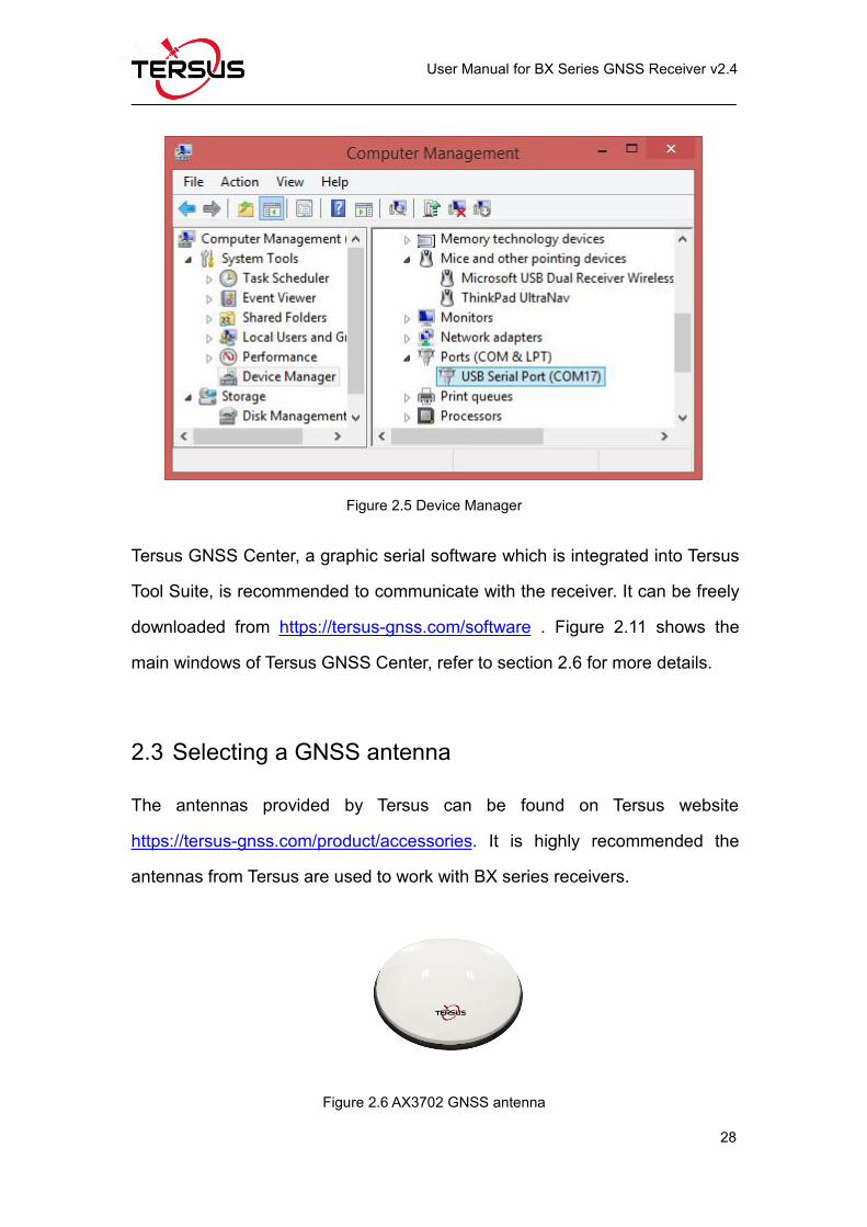
Figure 2.5 Device Manager
Tersus GNSS Center, a graphic serial software which is integrated into Tersus
Tool Suite, is recommended to communicate with the receiver. It can be freely
downloaded from https://tersus-gnss.com/software . Figure 2.11 shows the
main windows of Tersus GNSS Center, refer to section 2.6 for more details.
2.3 Selecting a GNSS antenna
The antennas provided by Tersus can be found on Tersus website
https://tersus-gnss.com/product/accessories. It is highly recommended the
antennas from Tersus are used to work with BX series receivers.
Figure 2.6 AX3702 GNSS antenna
Page 41
User Manual for BX Series GNSS Receiver v2.4
29
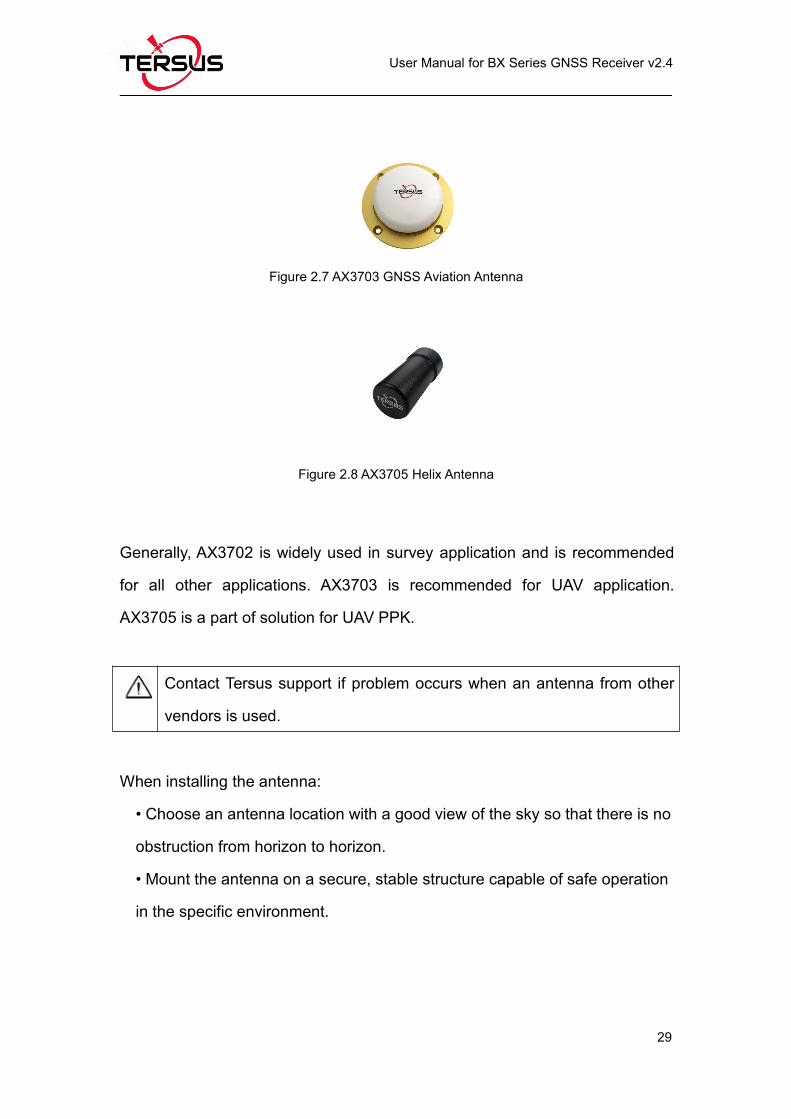
Figure 2.7 AX3703 GNSS Aviation Antenna
Figure 2.8 AX3705 Helix Antenna
Generally, AX3702 is widely used in survey application and is recommended
for all other applications. AX3703 is recommended for UAV application.
AX3705 is a part of solution for UAV PPK.
Contact Tersus support if problem occurs when an antenna from other
vendors is used.
When installing the antenna:
• Choose an antenna location with a good view of the sky so that there is no
obstruction from horizon to horizon.
• Mount the antenna on a secure, stable structure capable of safe operation
in the specific environment.
Page 42
User Manual for BX Series GNSS Receiver v2.4
30
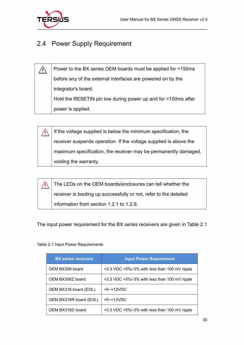
2.4 Power Supply Requirement
Power to the BX series OEM boards must be applied for >150ms
before any of the external interfaces are powered on by the
integrator's board.
Hold the RESETIN pin low during power up and for >150ms after
power is applied.
The input power requirement for the BX series receivers are given in Table 2.1
Table 2.1 Input Power Requirements
BX series receivers Input Power Requirement
OEM BX306 board +3.3 VDC +5%/-3% with less than 100 mV ripple
OEM BX306Z board +3.3 VDC +5%/-3% with less than 100 mV ripple
OEM BX316 board (EOL) +5~+12VDC
OEM BX316R board (EOL) +5~+12VDC
OEM BX316D board +3.3 VDC +5%/-3% with less than 100 mV ripple
If the voltage supplied is below the minimum specification, the
receiver suspends operation. If the voltage supplied is above the
maximum specification, the receiver may be permanently damaged,
voiding the warranty.
The LEDs on the OEM boards/enclosures can tell whether the
receiver is booting up successfully or not, refer to the detailed
information from section 1.2.1 to 1.2.9.
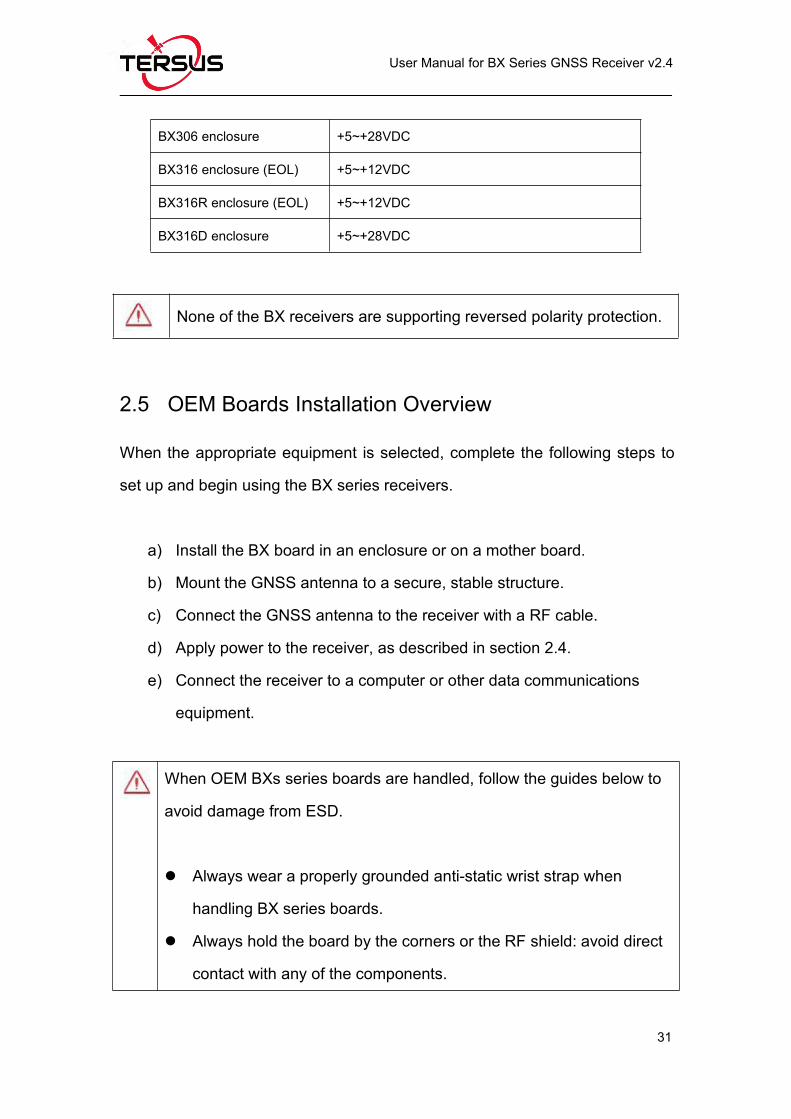
Page 43
User Manual for BX Series GNSS Receiver v2.4
31
BX306 enclosure +5~+28VDC
BX316 enclosure (EOL) +5~+12VDC
BX316R enclosure (EOL) +5~+12VDC
BX316D enclosure +5~+28VDC
2.5 OEM Boards Installation Overview
When the appropriate equipment is selected, complete the following steps to
set up and begin using the BX series receivers.
a) Install the BX board in an enclosure or on a mother board.
b) Mount the GNSS antenna to a secure, stable structure.
c) Connect the GNSS antenna to the receiver with a RF cable.
d) Apply power to the receiver, as described in section 2.4.
e) Connect the receiver to a computer or other data communications
equipment.
When OEM BXs series boards are handled, follow the guides below to
avoid damage from ESD.
Always wear a properly grounded anti-static wrist strap when
handling BX series boards.
Always hold the board by the corners or the RF shield: avoid direct
contact with any of the components.
None of the BX receivers are supporting reversed polarity protection.
Page 44
User Manual for BX Series GNSS Receiver v2.4
32
Never let the board come in contact with clothing. The ground strap
cannot dissipate static charges from fabrics.
Failure to follow accepted ESD handling practices could cause
damage to the board permanently.
The warranty may be void if equipment is damaged by ESD.
2.6 Tersus GNSS Center Software
BX receivers have serial ports and USB port, hence lots of serial tools can be
used to communicate with the receivers. Tersus GNSS Center is a
windows-platform-based serial tool, which is recommended to communicate
with the BX receivers. Tersus GNSS Center can be downloaded from Tersus
website https://tersus-gnss.com/software .
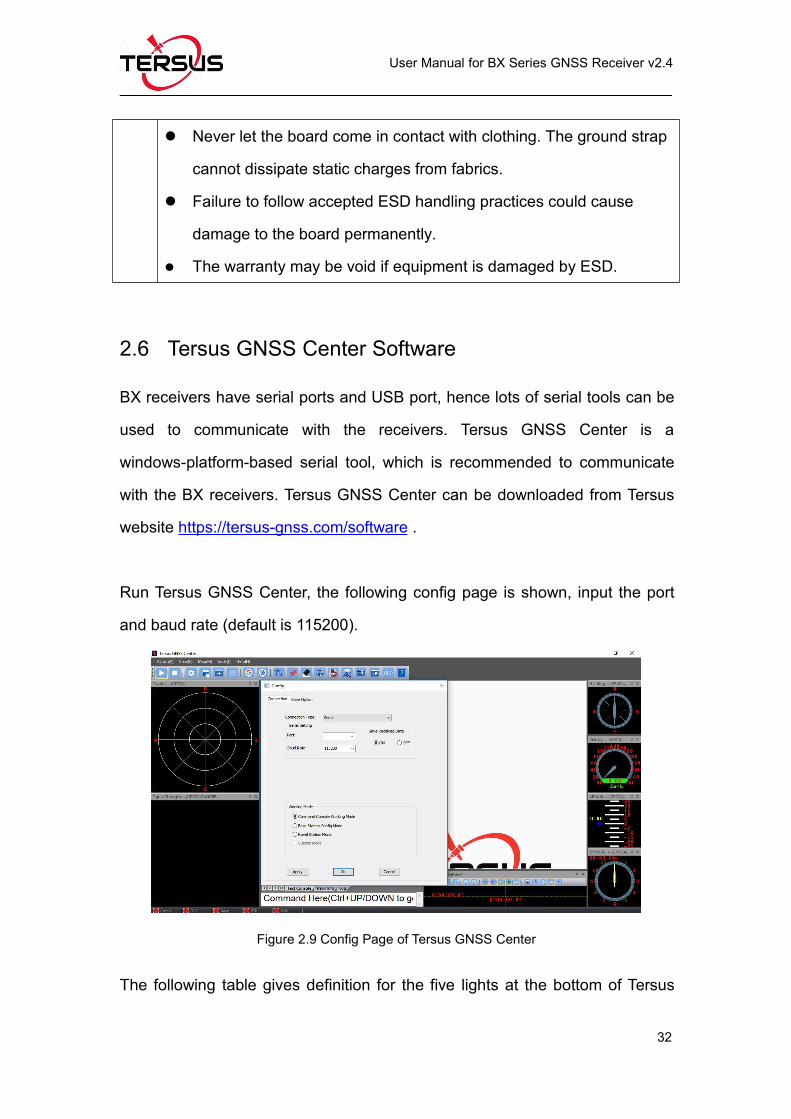
Run Tersus GNSS Center, the following config page is shown, input the port
and baud rate (default is 115200).
Figure 2.9 Config Page of Tersus GNSS Center
The following table gives definition for the five lights at the bottom of Tersus
Page 45
User Manual for BX Series GNSS Receiver v2.4
33
GNSS Center interface.
Table 2.2 Definition of the lights on Tersus GNSS Center
Lights Description
COMMGREEN: the communication with the receiver is established.RED: the communication with the receiver is not established.
GPSGREEN: valid GPGGA is received.RED: No valid GPGGA is received.
BaseGREEN: valid corrections are received.RED: No valid corrections are received.
RTKSOLID GREEN: RTK solution is got.BLINK GREEN: float solution is got.RED: other solutions are got.
Wifi Reserved.
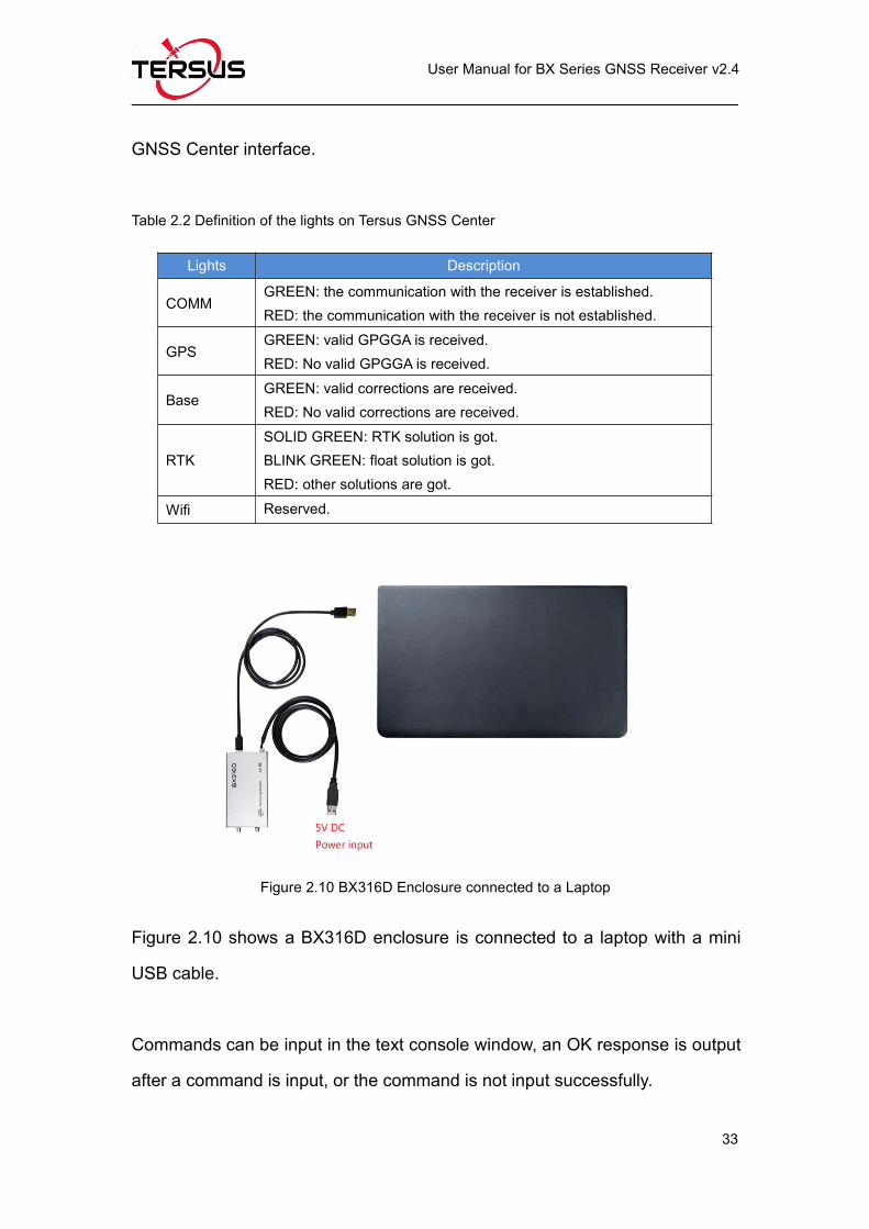
Figure 2.10 BX316D Enclosure connected to a Laptop
Figure 2.10 shows a BX316D enclosure is connected to a laptop with a mini
USB cable.
Commands can be input in the text console window, an OK response is output
after a command is input, or the command is not input successfully.
Page 46
User Manual for BX Series GNSS Receiver v2.4
34
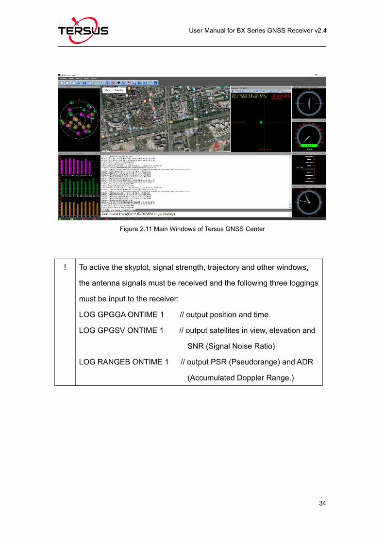
Figure 2.11 Main Windows of Tersus GNSS Center
! To active the skyplot, signal strength, trajectory and other windows,
the antenna signals must be received and the following three loggings
must be input to the receiver:
LOG GPGGAONTIME 1 // output position and time
LOG GPGSV ONTIME 1 // output satellites in view, elevation and
SNR (Signal Noise Ratio)
LOG RANGEB ONTIME 1 // output PSR (Pseudorange) and ADR
(Accumulated Doppler Range.)
Page 47
User Manual for BX Series GNSS Receiver v2.4
35
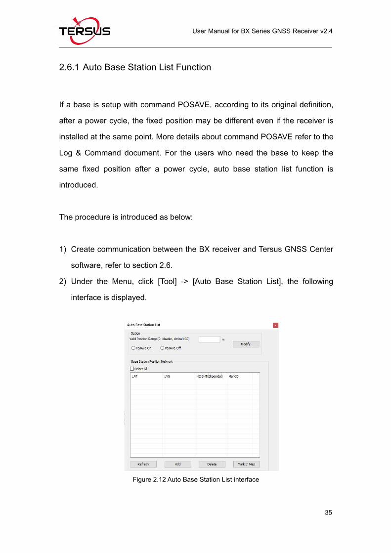
2.6.1 Auto Base Station List Function
If a base is setup with command POSAVE, according to its original definition,
after a power cycle, the fixed position may be different even if the receiver is
installed at the same point. More details about command POSAVE refer to the
Log & Command document. For the users who need the base to keep the
same fixed position after a power cycle, auto base station list function is
introduced.
The procedure is introduced as below:
1) Create communication between the BX receiver and Tersus GNSS Center
software, refer to section 2.6.
2) Under the Menu, click [Tool] -> [Auto Base Station List], the following
interface is displayed.
Figure 2.12 Auto Base Station List interface
Page 48
User Manual for BX Series GNSS Receiver v2.4
36
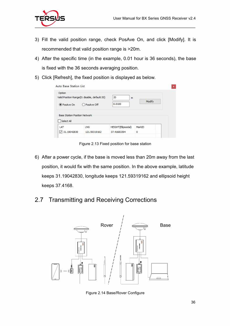
3) Fill the valid position range, check PosAve On, and click [Modify]. It is
recommended that valid position range is >20m.
4) After the specific time (in the example, 0.01 hour is 36 seconds), the base
is fixed with the 36 seconds averaging position.
5) Click [Refresh], the fixed position is displayed as below.
Figure 2.13 Fixed position for base station
6) After a power cycle, if the base is moved less than 20m away from the last
position, it would fix with the same position. In the above example, latitude
keeps 31.19042830, longitude keeps 121.59319162 and ellipsoid height
keeps 37.4168.
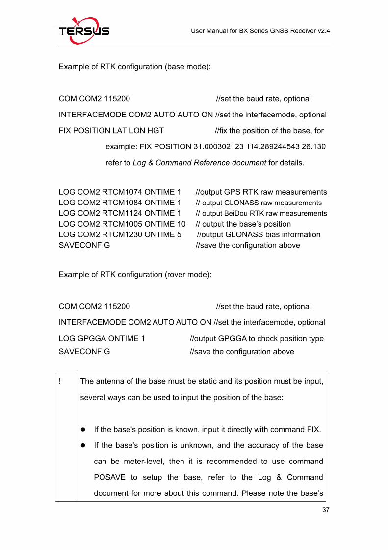
2.7 Transmitting and Receiving Corrections
Figure 2.14 Base/Rover Configure
Rover Base
Page 49
User Manual for BX Series GNSS Receiver v2.4
37
Example of RTK configuration (base mode):
COM COM2 115200 //set the baud rate, optional
INTERFACEMODE COM2 AUTO AUTO ON //set the interfacemode, optional
FIX POSITION LAT LON HGT //fix the position of the base, for
example: FIX POSITION 31.000302123 114.289244543 26.130
refer to Log & Command Reference document for details.
LOG COM2 RTCM1074 ONTIME 1 //output GPS RTK raw measurementsLOG COM2 RTCM1084 ONTIME 1 // output GLONASS raw measurementsLOG COM2 RTCM1124 ONTIME 1 // output BeiDou RTK raw measurementsLOG COM2 RTCM1005 ONTIME 10 // output the base’s positionLOG COM2 RTCM1230 ONTIME 5 //output GLONASS bias informationSAVECONFIG //save the configuration above
Example of RTK configuration (rover mode):
COM COM2 115200 //set the baud rate, optional
INTERFACEMODE COM2 AUTOAUTO ON //set the interfacemode, optional
LOG GPGGA ONTIME 1 //output GPGGA to check position typeSAVECONFIG //save the configuration above
! The antenna of the base must be static and its position must be input,
several ways can be used to input the position of the base:
If the base's position is known, input it directly with command FIX.
If the base's position is unknown, and the accuracy of the base
can be meter-level, then it is recommended to use command
POSAVE to setup the base, refer to the Log & Command
document for more about this command. Please note the base’s
Page 50
User Manual for BX Series GNSS Receiver v2.4
38
position will be different after a power cycle even if the antenna is
installed at the same point if POSAVE command is input.
If you require a cm level accuracy of base and rover, then:
a. Configure the base receiver as a rover, receive RTK corrections
from a CORS nearby, this receiver can get cm-level accuracy
position.
b. Collect raw measurements for half an hour, process it with post
processing software or send the data to an online processing
web, e.g. OPUS, to get an accurate position.
2.8 Heading Output
! Only BX316D board / enclosure and BX316 board / enclosure can
support heading output.
The default configuration of BX316D and BX316 is in single antenna mode;
heading output is supported only when they are in dual antenna mode. To
output heading, please ensure the antenna mode is configured as dual
antenna mode.
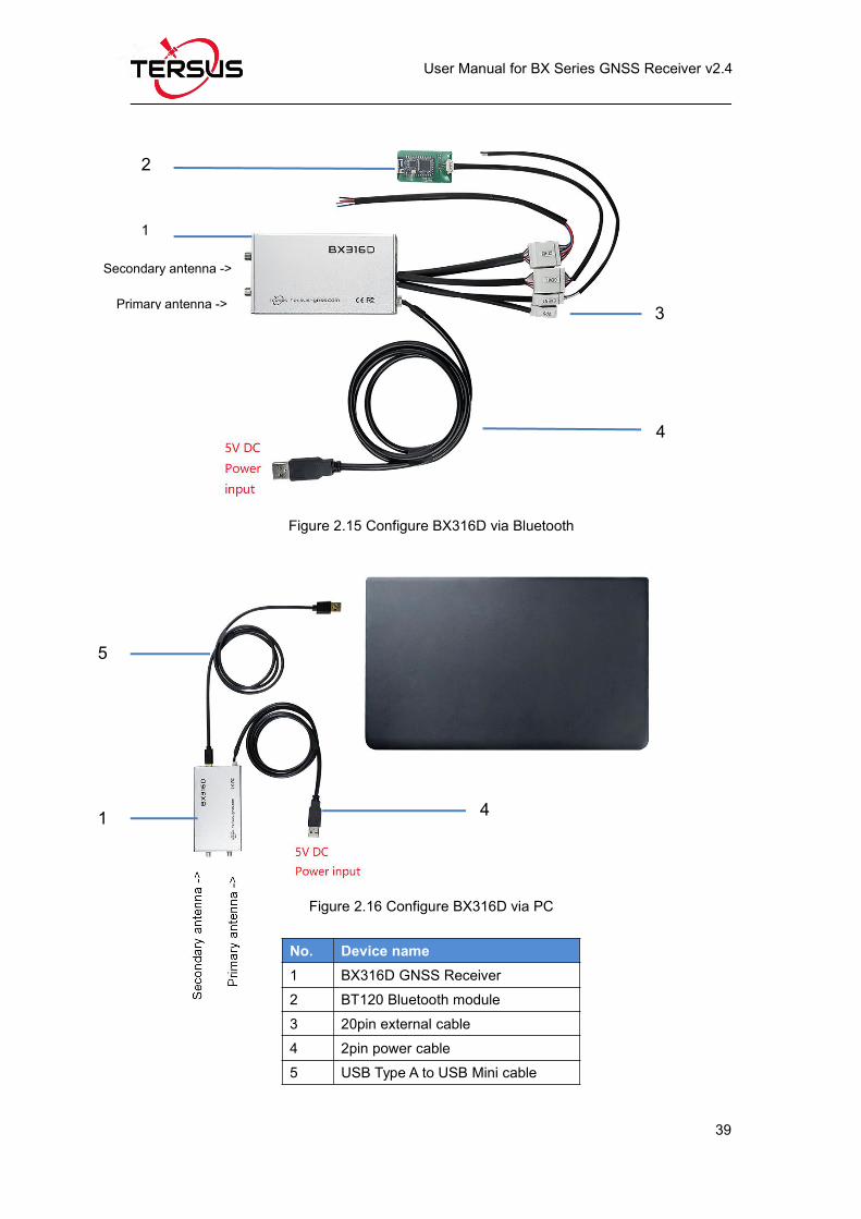
There are two methods to set antenna mode for BX316D: via Bluetooth, and
via a computer. Set up the hardware connection for BX316D as below.
Page 51
User Manual for BX Series GNSS Receiver v2.4
39
Figure 2.15 Configure BX316D via Bluetooth
Figure 2.16 Configure BX316D via PC
No. Device name1 BX316D GNSS Receiver2 BT120 Bluetooth module3 20pin external cable4 2pin power cable5 USB Type A to USB Mini cable
1
1
2
3
4
5
4
Secondary antenna ->
Primary antenna ->
Page 52
User Manual for BX Series GNSS Receiver v2.4
40
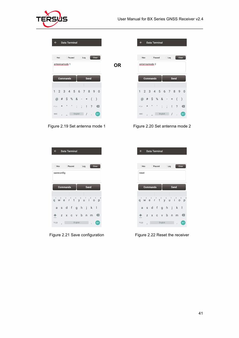
The steps of antenna mode setting via Nuwa app are as follows:a. Open Nuwa app on an android device, click [Device] -> [Connect];
Figure 2.17 Device -> Connect Figure 2.18 Connect interface
b. Select [David] as Device Type, select [Bluetooth] as Connect Type, click[Connect Config] to search the corresponding Bluetooth address and pair,select the antenna to be connected with David Plus in the [Antenna] option;
c. Click [Connect] at the bottom to enable the communication with David Plus;d. Back to [Device] -> [Data Terminal], type below command and click [Send]
to set single antenna mode or dual antenna mode.antennamode 2 //set antenna mode, 0: single; 1: GPS&GLONASS; 2: GPS&BeiDou
saveconfig //save configuration
reset //or power cycle the receiver to make it effective
Page 53
User Manual for BX Series GNSS Receiver v2.4
41
Figure 2.19 Set antenna mode 1 Figure 2.20 Set antenna mode 2
Figure 2.21 Save configuration Figure 2.22 Reset the receiver
OR
Page 54
User Manual for BX Series GNSS Receiver v2.4
42
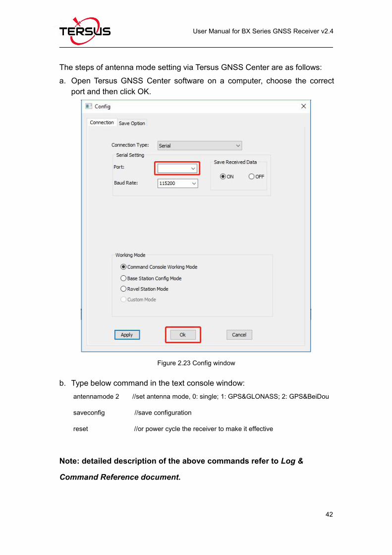
The steps of antenna mode setting via Tersus GNSS Center are as follows:a. Open Tersus GNSS Center software on a computer, choose the correct
port and then click OK.
Figure 2.23 Config window
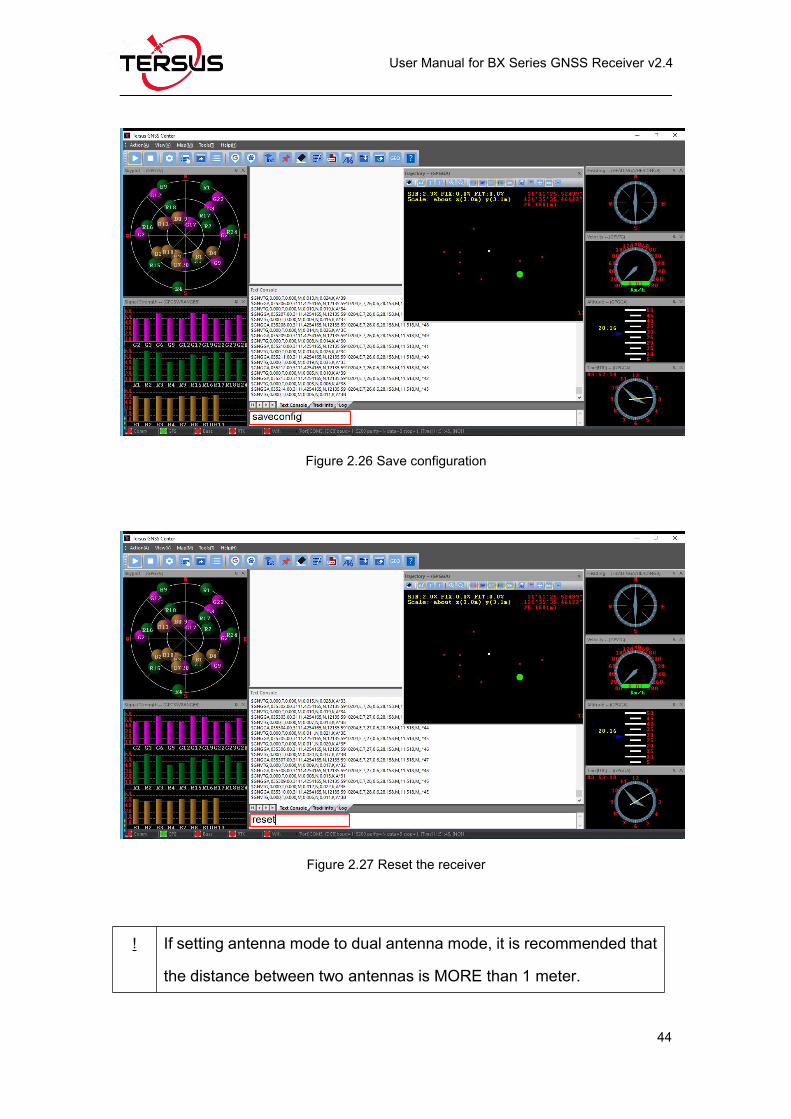
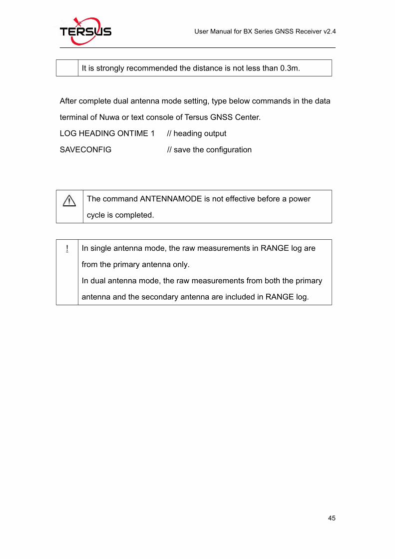
b. Type below command in the text console window:antennamode 2 //set antenna mode, 0: single; 1: GPS&GLONASS; 2: GPS&BeiDou
saveconfig //save configuration
reset //or power cycle the receiver to make it effective
Note: detailed description of the above commands refer to Log &
Command Reference document.
Page 55
User Manual for BX Series GNSS Receiver v2.4
43
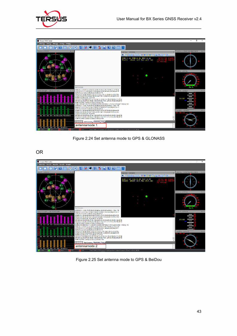
Figure 2.24 Set antenna mode to GPS & GLONASS
OR
Figure 2.25 Set antenna mode to GPS & BeiDou
Page 56
User Manual for BX Series GNSS Receiver v2.4
44
Figure 2.26 Save configuration
Figure 2.27 Reset the receiver
! If setting antenna mode to dual antenna mode, it is recommended that
the distance between two antennas is MORE than 1 meter.
Page 57
User Manual for BX Series GNSS Receiver v2.4
45
It is strongly recommended the distance is not less than 0.3m.
After complete dual antenna mode setting, type below commands in the data
terminal of Nuwa or text console of Tersus GNSS Center.
LOG HEADING ONTIME 1 // heading output
SAVECONFIG // save the configuration
The command ANTENNAMODE is not effective before a power
cycle is completed.
! In single antenna mode, the raw measurements in RANGE log are
from the primary antenna only.
In dual antenna mode, the raw measurements from both the primary
antenna and the secondary antenna are included in RANGE log.
Page 58
User Manual for BX Series GNSS Receiver v2.4
46
3. Firmware Update and Auth Code
3.1 Firmware Update Overview
If a new firmware update is released, it will be available on the Tersus web site
https://www.tersus-gnss.com/software , or you can get the updates from
Tersus technical support by email [email protected] .
The firmware version of a Tersus receiver can be updated in field. Connect the
COM2 port of the receiver with Tersus GNSS Center, and input ‘LOG
VERSION’ in the text console, the following info will be output:
VERSION COM1 0 0.0 UNKNOWN -1 0.000 00000000 0 20161214
< 1
< BX306 G2SB2G2 008001181300000026 0020 20161123 3.0 Mar 16
2018 00:39:52
0020 is the firmware version. Refer to ‘VERSION’ in Tersus GNSS Log &
Command Reference document for more details.
Page 59
User Manual for BX Series GNSS Receiver v2.4
47
3.2 Firmware Update Using Tersus GNSS Center
Please follow the steps below to upgrade the firmware.
1) Power on the GNSS receiver;
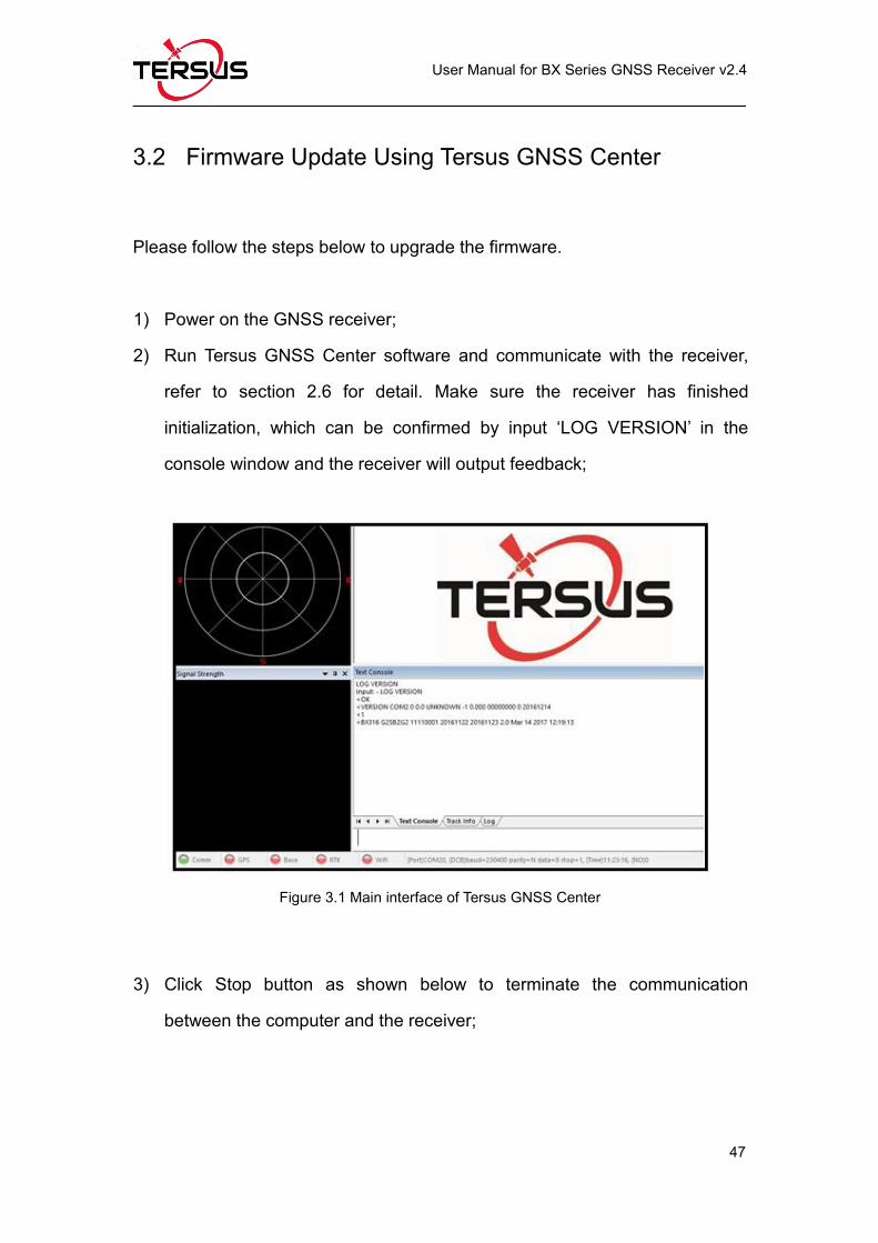
2) Run Tersus GNSS Center software and communicate with the receiver,
refer to section 2.6 for detail. Make sure the receiver has finished
initialization, which can be confirmed by input ‘LOG VERSION’ in the
console window and the receiver will output feedback;
Figure 3.1 Main interface of Tersus GNSS Center
3) Click Stop button as shown below to terminate the communication
between the computer and the receiver;
Page 60
User Manual for BX Series GNSS Receiver v2.4
48
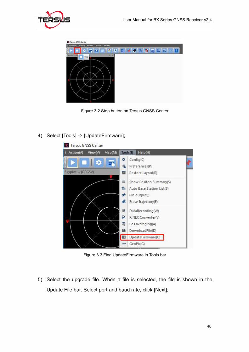
Figure 3.2 Stop button on Tersus GNSS Center
4) Select [Tools] -> [UpdateFirmware];
Figure 3.3 Find UpdateFirmware in Tools bar
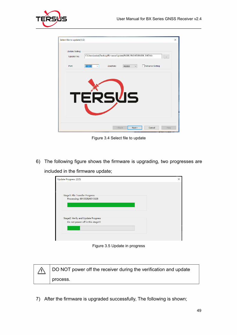
5) Select the upgrade file. When a file is selected, the file is shown in the
Update File bar. Select port and baud rate, click [Next];
Page 61
User Manual for BX Series GNSS Receiver v2.4
49
Figure 3.4 Select file to update
6) The following figure shows the firmware is upgrading, two progresses are
included in the firmware update;
Figure 3.5 Update in progress
DO NOT power off the receiver during the verification and update
process.
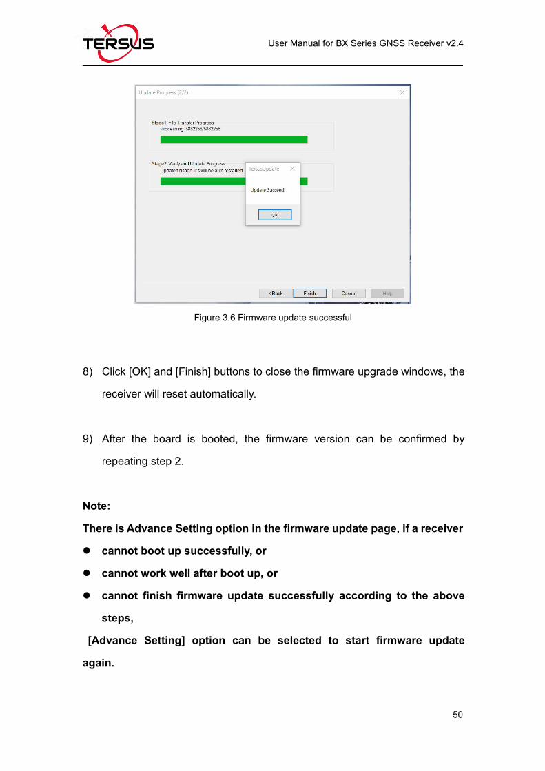
7) After the firmware is upgraded successfully, The following is shown;
Page 62
User Manual for BX Series GNSS Receiver v2.4
50
Figure 3.6 Firmware update successful
8) Click [OK] and [Finish] buttons to close the firmware upgrade windows, the
receiver will reset automatically.
9) After the board is booted, the firmware version can be confirmed by
repeating step 2.
Note:
There is Advance Setting option in the firmware update page, if a receiver
cannot boot up successfully, or
cannot work well after boot up, or
cannot finish firmware update successfully according to the above
steps,
[Advance Setting] option can be selected to start firmware update
again.
Page 63
User Manual for BX Series GNSS Receiver v2.4
51
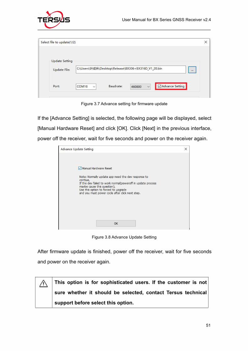
Figure 3.7 Advance setting for firmware update
If the [Advance Setting] is selected, the following page will be displayed, select
[Manual Hardware Reset] and click [OK]. Click [Next] in the previous interface,
power off the receiver, wait for five seconds and power on the receiver again.
Figure 3.8 Advance Update Setting
After firmware update is finished, power off the receiver, wait for five seconds
and power on the receiver again.
This option is for sophisticated users. If the customer is not
sure whether it should be selected, contact Tersus technical
support before select this option.
Page 64
User Manual for BX Series GNSS Receiver v2.4
52
3.3 Auth Code
An auth code is used to determine the features and valid time for a receiver. If
the auth code is expired, the receiver will not work. And a license requirement
is output from all the ports.
Before contacting Tersus technical support for a new auth code, input:
LOG VERSION
LOG AUTHLIST
In the text console window of Tersus GNSS Center when the receiver is
connected with computer, and send all the output information to Tersus
technical support. If the auth code application is approved, you will get a txt file,
in which command AUTHCODE and the auth code will be given, copy all of
them (Ctrl + A & Ctrl + C) and paste them to the text console window of Tersus
GNSS Center when the receiver is connected with computer.
Page 65
User Manual for BX Series GNSS Receiver v2.4
53
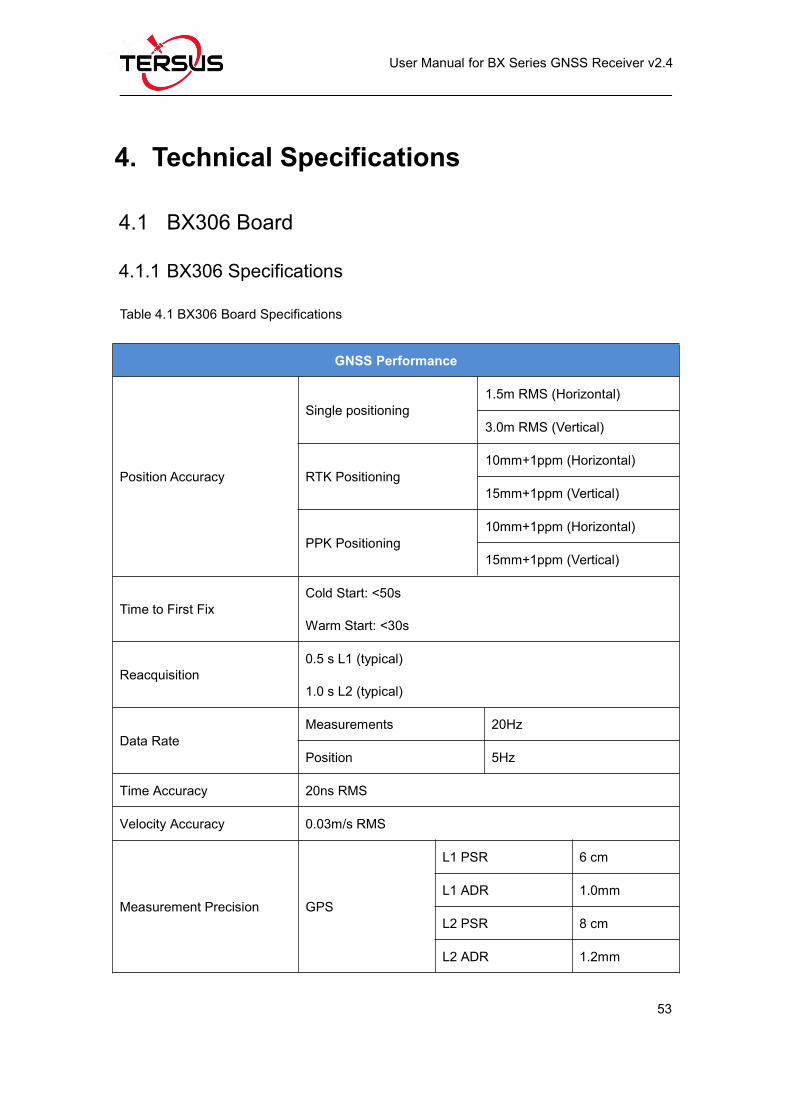
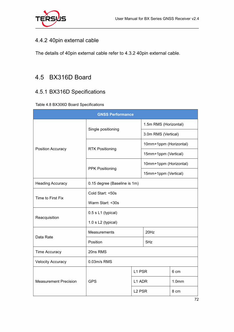
4. Technical Specifications
4.1 BX306 Board
4.1.1 BX306 Specifications
Table 4.1 BX306 Board Specifications
GNSS Performance
Position Accuracy
Single positioning1.5m RMS (Horizontal)
3.0m RMS (Vertical)
RTK Positioning10mm+1ppm (Horizontal)
15mm+1ppm (Vertical)
PPK Positioning10mm+1ppm (Horizontal)
15mm+1ppm (Vertical)
Time to First FixCold Start: <50s
Warm Start: <30s
Reacquisition0.5 s L1 (typical)
1.0 s L2 (typical)
Data RateMeasurements 20Hz
Position 5Hz
Time Accuracy 20ns RMS
Velocity Accuracy 0.03m/s RMS
Measurement Precision GPS
L1 PSR 6 cm
L1 ADR 1.0mm
L2 PSR 8 cm
L2 ADR 1.2mm
Page 66
User Manual for BX Series GNSS Receiver v2.4
54
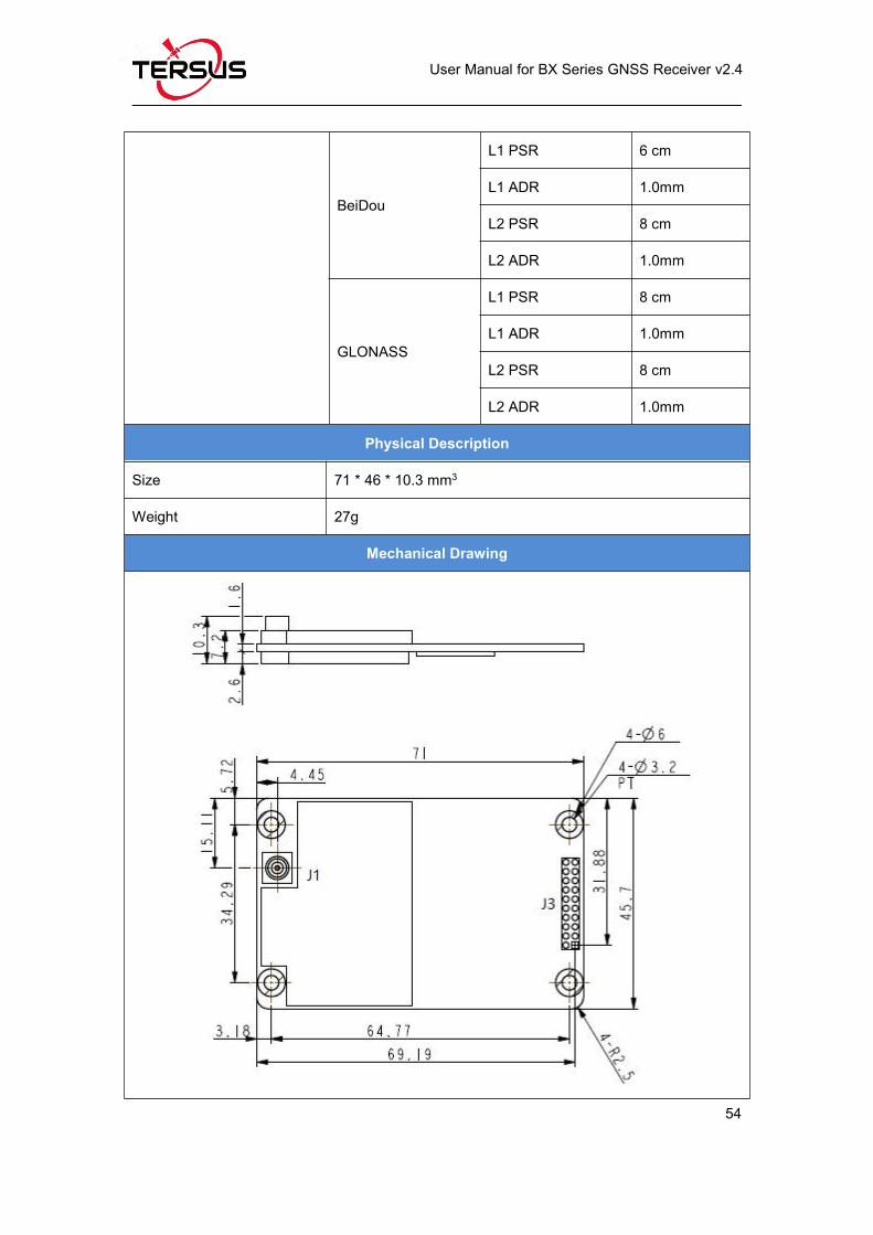
BeiDou
L1 PSR 6 cm
L1 ADR 1.0mm
L2 PSR 8 cm
L2 ADR 1.0mm
GLONASS
L1 PSR 8 cm
L1 ADR 1.0mm
L2 PSR 8 cm
L2 ADR 1.0mm
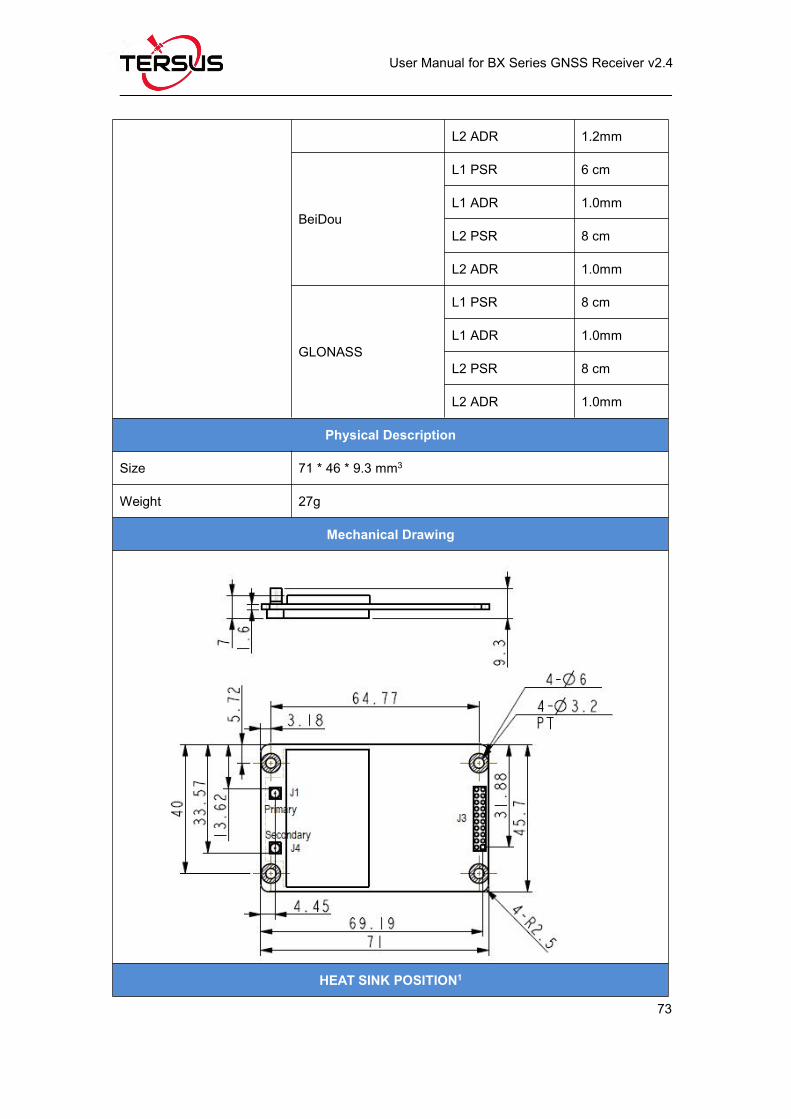
Physical Description
Size 71 * 46 * 10.3 mm3
Weight 27g
Mechanical Drawing
Page 67
User Manual for BX Series GNSS Receiver v2.4
55
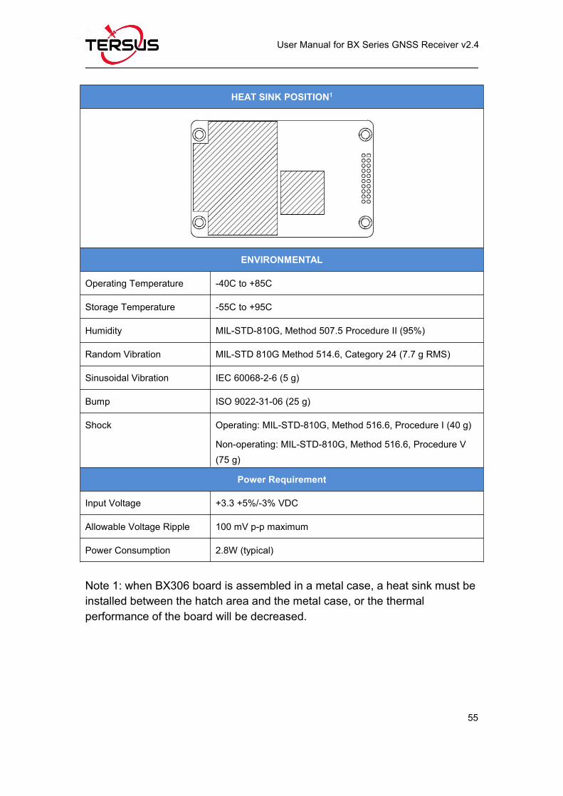
HEAT SINK POSITION1
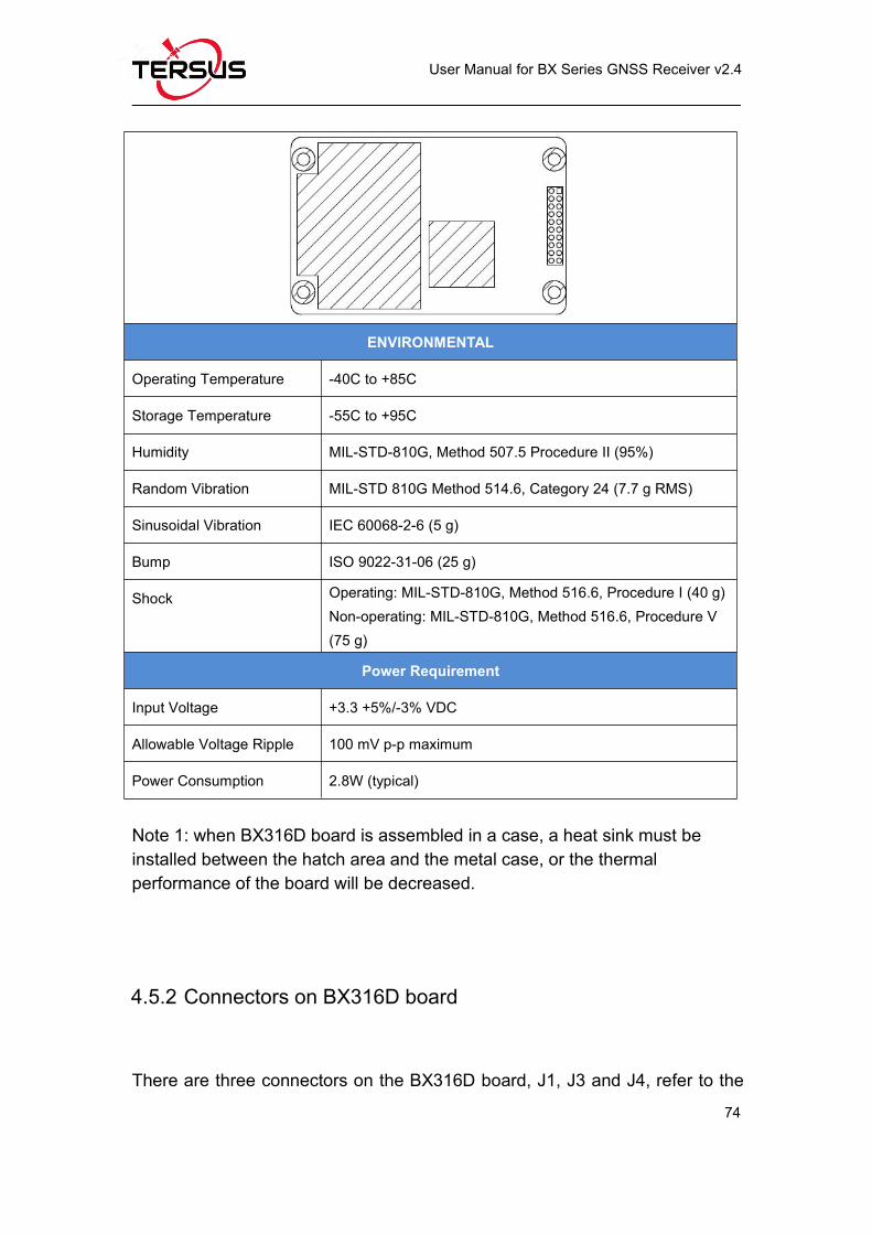
ENVIRONMENTAL
Operating Temperature -40C to +85C
Storage Temperature -55C to +95C
Humidity MIL-STD-810G, Method 507.5 Procedure II (95%)
Random Vibration MIL-STD 810G Method 514.6, Category 24 (7.7 g RMS)
Sinusoidal Vibration IEC 60068-2-6 (5 g)
Bump ISO 9022-31-06 (25 g)
Shock Operating: MIL-STD-810G, Method 516.6, Procedure I (40 g)
Non-operating: MIL-STD-810G, Method 516.6, Procedure V(75 g)
Power Requirement
Input Voltage +3.3 +5%/-3% VDC
Allowable Voltage Ripple 100 mV p-p maximum
Power Consumption 2.8W (typical)
Note 1: when BX306 board is assembled in a metal case, a heat sink must beinstalled between the hatch area and the metal case, or the thermalperformance of the board will be decreased.
Page 68
User Manual for BX Series GNSS Receiver v2.4
56
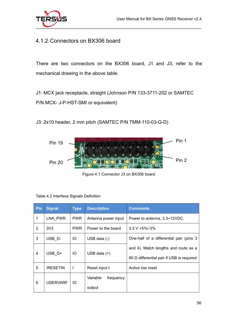
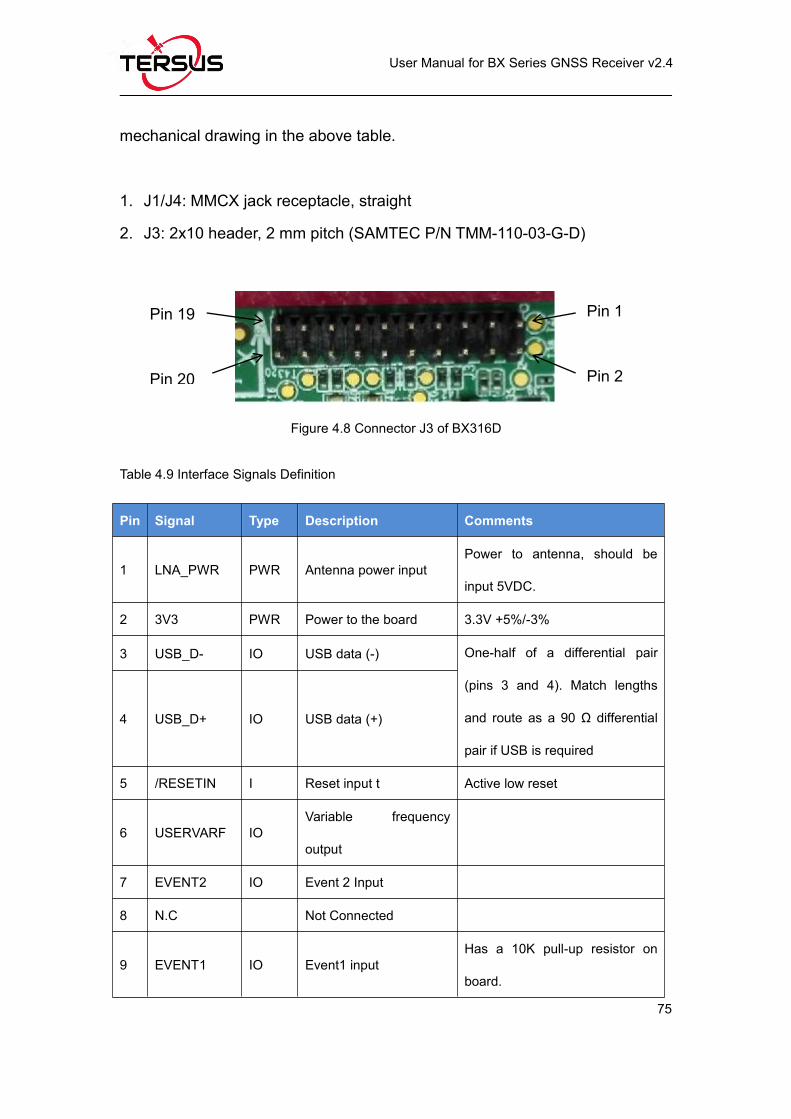
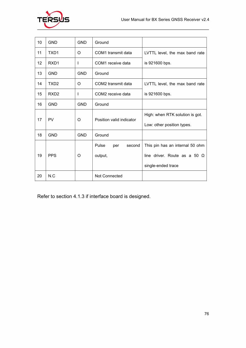
4.1.2 Connectors on BX306 board
There are two connectors on the BX306 board, J1 and J3, refer to the
mechanical drawing in the above table.
J1: MCX jack receptacle, straight (Johnson P/N 133-3711-202 or SAMTEC
P/N MCX- J-P-HST-SMI or equivalent)
J3: 2x10 header, 2 mm pitch (SAMTEC P/N TMM-110-03-G-D)
Figure 4.1 Connector J3 on BX306 board
Table 4.2 Interface Signals Definition
Pin Signal Type Description Comments
1 LNA_PWR PWR Antenna power input Power to antenna, 3.3~12VDC.
2 3V3 PWR Power to the board 3.3 V +5%/-3%
3 USB_D- IO USB data (-) One-half of a differential pair (pins 3
and 4). Match lengths and route as a
90 Ω differential pair if USB is required4 USB_D+ IO USB data (+)
5 /RESETIN I Reset input t Active low reset
6 USERVARF IOVariable frequency
output
Pin 1
Pin 2
Pin 19
Pin 20
Page 69
User Manual for BX Series GNSS Receiver v2.4
57
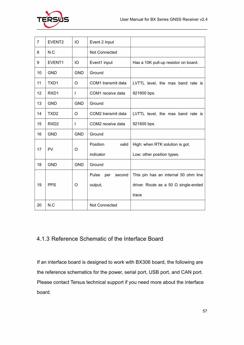
7 EVENT2 IO Event 2 Input
8 N.C Not Connected
9 EVENT1 IO Event1 input Has a 10K pull-up resistor on board.
10 GND GND Ground
11 TXD1 O COM1 transmit data LVTTL level, the max band rate is
921600 bps.12 RXD1 I COM1 receive data
13 GND GND Ground
14 TXD2 O COM2 transmit data LVTTL level, the max band rate is
921600 bps.15 RXD2 I COM2 receive data
16 GND GND Ground
17 PV OPosition valid
indicator
High: when RTK solution is got.
Low: other position types.
18 GND GND Ground
19 PPS O
Pulse per second
output,
This pin has an internal 50 ohm line
driver. Route as a 50 Ω single-ended
trace
20 N.C Not Connected
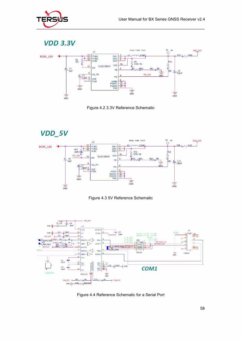
4.1.3 Reference Schematic of the Interface Board
If an interface board is designed to work with BX306 board, the following are
the reference schematics for the power, serial port, USB port, and CAN port.
Please contact Tersus technical support if you need more about the interface
board.
Page 70
User Manual for BX Series GNSS Receiver v2.4
58
Figure 4.2 3.3V Reference Schematic
Figure 4.3 5V Reference Schematic
Figure 4.4 Reference Schematic for a Serial Port
Page 71
User Manual for BX Series GNSS Receiver v2.4
59
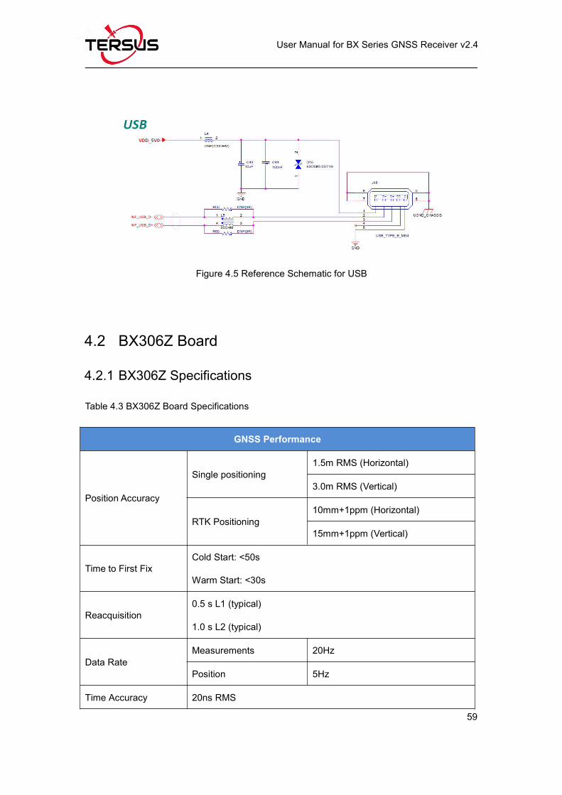
Figure 4.5 Reference Schematic for USB
4.2 BX306Z Board
4.2.1 BX306Z Specifications
Table 4.3 BX306Z Board Specifications
GNSS Performance
Position Accuracy
Single positioning1.5m RMS (Horizontal)
3.0m RMS (Vertical)
RTK Positioning10mm+1ppm (Horizontal)
15mm+1ppm (Vertical)
Time to First FixCold Start: <50s
Warm Start: <30s
Reacquisition0.5 s L1 (typical)
1.0 s L2 (typical)
Data RateMeasurements 20Hz
Position 5Hz
Time Accuracy 20ns RMS
Page 72
User Manual for BX Series GNSS Receiver v2.4
60
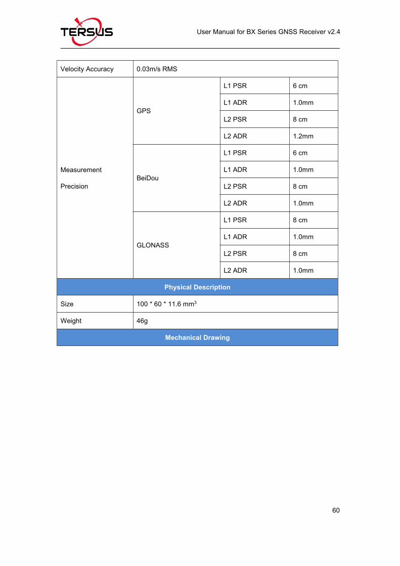
Velocity Accuracy 0.03m/s RMS
Measurement
Precision
GPS
L1 PSR 6 cm
L1 ADR 1.0mm
L2 PSR 8 cm
L2 ADR 1.2mm
BeiDou
L1 PSR 6 cm
L1 ADR 1.0mm
L2 PSR 8 cm
L2 ADR 1.0mm
GLONASS
L1 PSR 8 cm
L1 ADR 1.0mm
L2 PSR 8 cm
L2 ADR 1.0mm
Physical Description
Size 100 * 60 * 11.6 mm3
Weight 46g
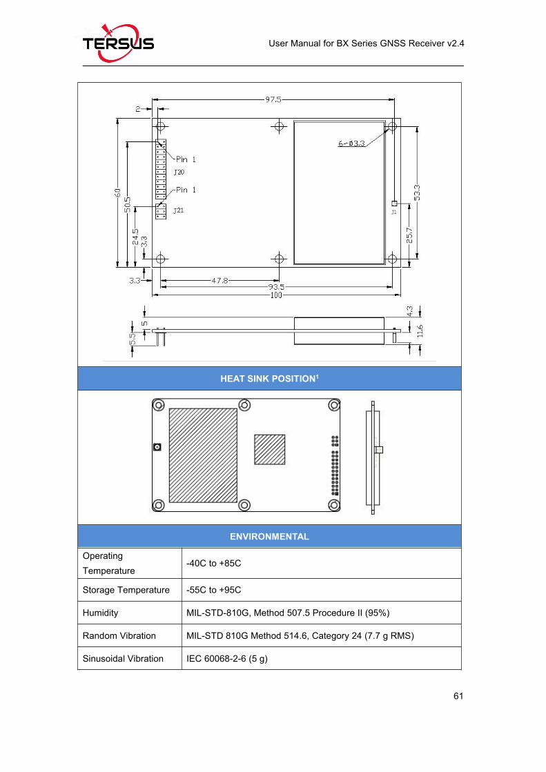
Mechanical Drawing
Page 73
User Manual for BX Series GNSS Receiver v2.4
61
HEAT SINK POSITION1
ENVIRONMENTAL
OperatingTemperature
-40C to +85C
Storage Temperature -55C to +95C
Humidity MIL-STD-810G, Method 507.5 Procedure II (95%)
Random Vibration MIL-STD 810G Method 514.6, Category 24 (7.7 g RMS)
Sinusoidal Vibration IEC 60068-2-6 (5 g)
Page 74
User Manual for BX Series GNSS Receiver v2.4
62
Bump ISO 9022-31-06 (25 g)
Shock Operating: MIL-STD-810G, Method 516.6, Procedure I (40 g)
Non-operating: MIL-STD-810G, Method 516.6, Procedure V (75 g)
Power Requirement
Input Voltage +3.3 +5%/-3% VDC
Allowable Voltage
Ripple
100 mV p-p maximum
Power Consumption 2.9W (typical)
Note 1: when BX306Z board is assembled in a case, a heat sink must beinstalled between the hatch area and the metal case, or the thermalperformance of the board will be decreased.
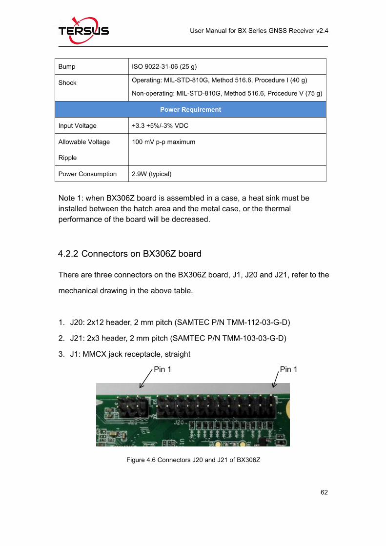
4.2.2 Connectors on BX306Z board
There are three connectors on the BX306Z board, J1, J20 and J21, refer to the
mechanical drawing in the above table.
1. J20: 2x12 header, 2 mm pitch (SAMTEC P/N TMM-112-03-G-D)
2. J21: 2x3 header, 2 mm pitch (SAMTEC P/N TMM-103-03-G-D)
3. J1: MMCX jack receptacle, straight
Figure 4.6 Connectors J20 and J21 of BX306Z
Pin 1 Pin 1
Page 75
User Manual for BX Series GNSS Receiver v2.4
63
Table 4.4 2X12 Header Signals Definition
Pin Signal Type Description Comments
1 GND GND Ground
2 RTK LED ORTK LED. Flasheswhen an RTKcorrection is present.
To drive an LED, a series resistorwith a 300Ohms is required.
3 POWER_OFF IPowers the unit on and
off.
Drive high with a 3.3V to turn off,
leave floating or ground to keep
the unit on.
4 PPS OPulse per second
output
This is 3.3V TTL level, 4mA maxdrive capability.
5 VCC PWR Power to the board 3.3V +5%/-3%
6 VCC PWR Power to the board 3.3V +5%/-3%
7Event21 /CAN1_RX /COM3_RX1
I
Event2 – Event inputCAN1_RX – CANReceive line
COM3_RX – COM3
Receive line
Event2 must be 3.3V TTL level.
Connect COM3_RX to atransceiver if RS-232 level isrequired.
8 Event1 I Event input must be 3.3 V TTL level
9 Power LED OPOWER Indicator,High when unit is on.
When used to drive an LED, aseries resistor with a typical valueof 300Ohm is required.
10 Satellite LED O
Satellite LED.Rapid flash: <5satellites. Slowflash: >5 satellites.
To drive an LED, a series resistorwith 300Ohm is required.
11 COM2_CTS ICOM2 Clear to Send –TTL Level
Connect COM2_CTS to atransceiver if RS-232 level isrequired.
12 RESET_IN IRESET_IN – ground toreset
Drive low to reset the unit.
13 COM2_RTS O COM2 Request to Connect COM2_RTS to a
Page 76
User Manual for BX Series GNSS Receiver v2.4
64
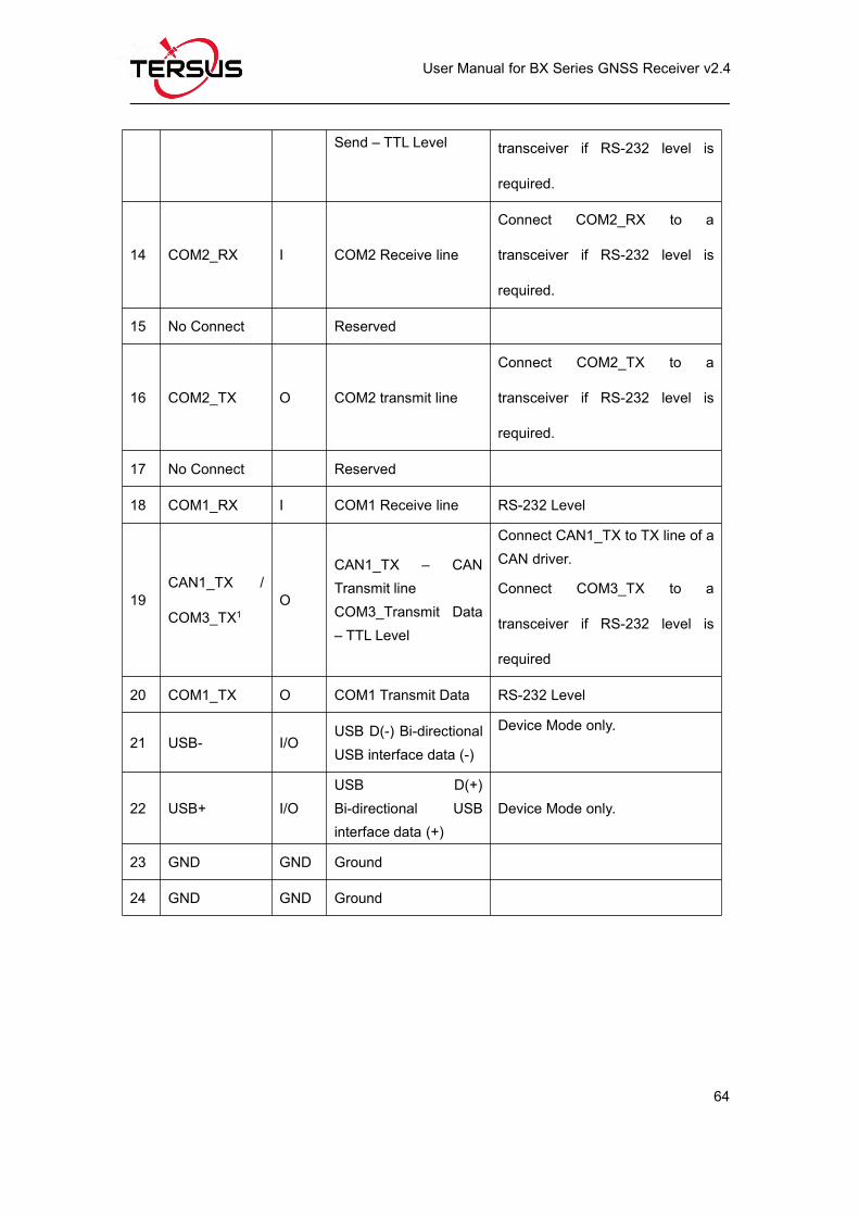
Send – TTL Level transceiver if RS-232 level is
required.
14 COM2_RX I COM2 Receive line
Connect COM2_RX to a
transceiver if RS-232 level is
required.
15 No Connect Reserved
16 COM2_TX O COM2 transmit line
Connect COM2_TX to a
transceiver if RS-232 level is
required.
17 No Connect Reserved
18 COM1_RX I COM1 Receive line RS-232 Level
19CAN1_TX /
COM3_TX1O
CAN1_TX – CANTransmit lineCOM3_Transmit Data– TTL Level
Connect CAN1_TX to TX line of aCAN driver.
Connect COM3_TX to a
transceiver if RS-232 level is
required
20 COM1_TX O COM1 Transmit Data RS-232 Level
21 USB- I/OUSB D(-) Bi-directionalUSB interface data (-)
Device Mode only.
22 USB+ I/OUSB D(+)Bi-directional USBinterface data (+)
Device Mode only.
23 GND GND Ground
24 GND GND Ground
Page 77
User Manual for BX Series GNSS Receiver v2.4
65
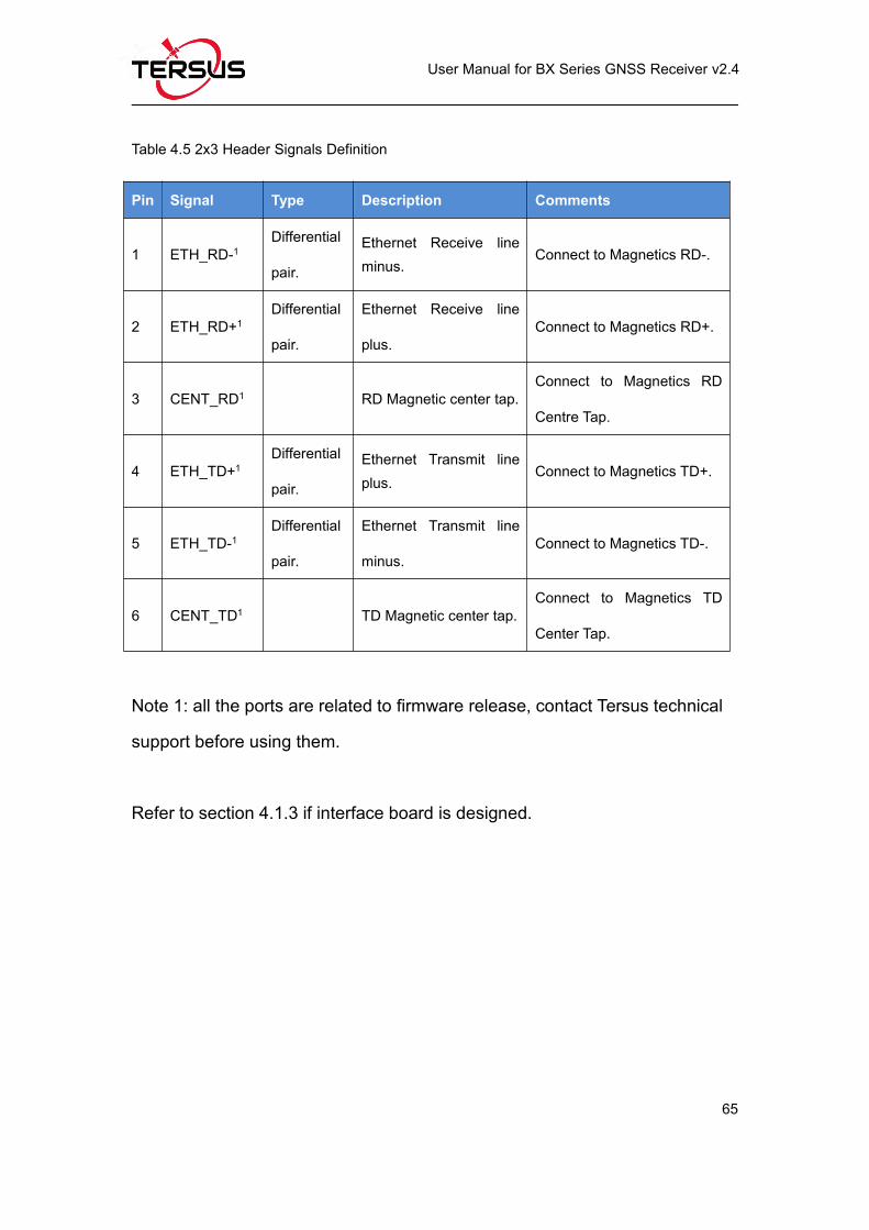
Table 4.5 2x3 Header Signals Definition
Pin Signal Type Description Comments
1 ETH_RD-1Differential
pair.
Ethernet Receive lineminus.
Connect to Magnetics RD-.
2 ETH_RD+1Differential
pair.
Ethernet Receive line
plus.Connect to Magnetics RD+.
3 CENT_RD1 RD Magnetic center tap.Connect to Magnetics RD
Centre Tap.
4 ETH_TD+1Differential
pair.
Ethernet Transmit lineplus.
Connect to Magnetics TD+.
5 ETH_TD-1Differential
pair.
Ethernet Transmit line
minus.Connect to Magnetics TD-.
6 CENT_TD1 TD Magnetic center tap.Connect to Magnetics TD
Center Tap.
Note 1: all the ports are related to firmware release, contact Tersus technical
support before using them.
Refer to section 4.1.3 if interface board is designed.
Page 78
User Manual for BX Series GNSS Receiver v2.4
66
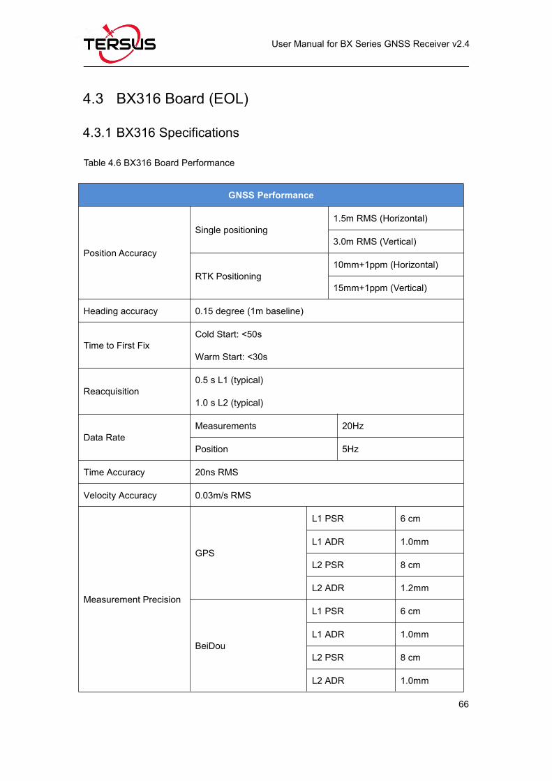
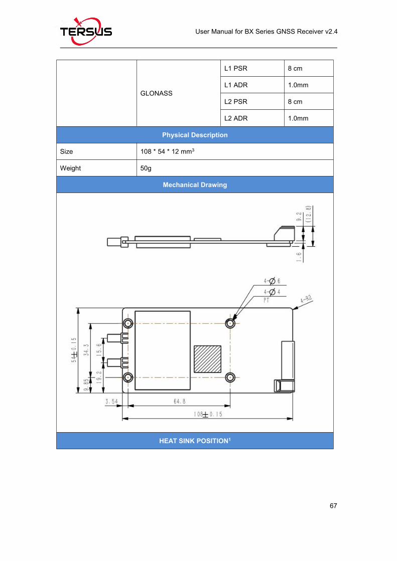
4.3 BX316 Board (EOL)
4.3.1 BX316 Specifications
Table 4.6 BX316 Board Performance
GNSS Performance
Position Accuracy
Single positioning1.5m RMS (Horizontal)
3.0m RMS (Vertical)
RTK Positioning10mm+1ppm (Horizontal)
15mm+1ppm (Vertical)
Heading accuracy 0.15 degree (1m baseline)
Time to First FixCold Start: <50s
Warm Start: <30s
Reacquisition0.5 s L1 (typical)
1.0 s L2 (typical)
Data RateMeasurements 20Hz
Position 5Hz
Time Accuracy 20ns RMS
Velocity Accuracy 0.03m/s RMS
Measurement Precision
GPS
L1 PSR 6 cm
L1 ADR 1.0mm
L2 PSR 8 cm
L2 ADR 1.2mm
BeiDou
L1 PSR 6 cm
L1 ADR 1.0mm
L2 PSR 8 cm
L2 ADR 1.0mm
Page 79
User Manual for BX Series GNSS Receiver v2.4
67
GLONASS
L1 PSR 8 cm
L1 ADR 1.0mm
L2 PSR 8 cm
L2 ADR 1.0mm
Physical Description
Size 108 * 54 * 12 mm3
Weight 50g
Mechanical Drawing
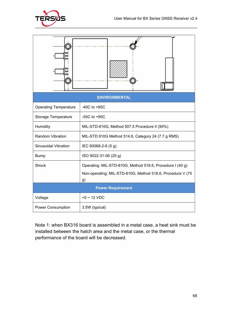
HEAT SINK POSITION1
Page 80
User Manual for BX Series GNSS Receiver v2.4
68
ENVIRONMENTAL
Operating Temperature -40C to +85C
Storage Temperature -55C to +95C
Humidity MIL-STD-810G, Method 507.5 Procedure II (95%)
Random Vibration MIL-STD 810G Method 514.6, Category 24 (7.7 g RMS)
Sinusoidal Vibration IEC 60068-2-6 (5 g)
Bump ISO 9022-31-06 (25 g)
Shock Operating: MIL-STD-810G, Method 516.6, Procedure I (40 g)
Non-operating: MIL-STD-810G, Method 516.6, Procedure V (75g)
Power Requirement
Voltage +5 ~ 12 VDC
Power Consumption 3.5W (typical)
Note 1: when BX316 board is assembled in a metal case, a heat sink must beinstalled between the hatch area and the metal case, or the thermalperformance of the board will be decreased.
Page 81
User Manual for BX Series GNSS Receiver v2.4
69
4.3.2 40pin external cable
A 40pin external cable is provided with the BX316/BX316R board and
enclosure.
Figure 4.7 Outline of the 40pin external cable
The 40pin connector of the cable is Mouser’s DF50S-40DS-1L or equivalent,
the connectors at the other side of the cable are 3pcs Mouser’s
7980DF1EA-6EP-2.5C and 2pcs 7980DF1EA-2EP-2.5C:
Page 82
User Manual for BX Series GNSS Receiver v2.4
70
Table 4.7 Pin Definition of the 40pin external cablePinNo.
Sign
al
Nam
e
Ethe
rnet
COM1
COM2
USB
CAN
1
CAN
2
Even
t1
Even
t2
PPS
1 N.C
2 TD1+ 1
3 EVENT2 1
4 TD1- 2
5 GND 2
6 LED0 6
7 RD1+ 4
8 LED1 7
9 RD1- 5
10 GND 8
11 GND 3
12 GND 2
13 N.C
14 EVENT1 1
15 GND 2
16 PPS 1
17 GND 6
18 COM1_RXD 3
19 SDA 5
20 COM1_TXD 2
21 SCL 4
22 GND 6
Page 83
User Manual for BX Series GNSS Receiver v2.4
71
23 COM2_RXD 3
24 3.3V 1
25 COM2_TXD 2
26 3.3V 1
27 3.3V 1
28 CANH1_TXD 2
29 N.C
30 CANH1_RXD 3
31 OTG_5V 1
32 GND 4
33 USB_DM 2
34 3.3V 1
35 USB_DP 3
36 CANH2_TXD 2
37 USB_ID 4
38 CANH2_RXD 3
39 GND 5
40 GND 4
4.4 BX316R Board (EOL)
4.4.1 BX316R Specifications
The specifications of BX316R board is the same with that of BX316 board,
refer to Table 4.6 BX316 Board Performance for details. The difference
between BX316 and BX316R is the firmware, and BX316R supports PPK
while BX316 supports RTK.
Page 84
User Manual for BX Series GNSS Receiver v2.4
72
4.4.2 40pin external cable
The details of 40pin external cable refer to 4.3.2 40pin external cable.
4.5 BX316D Board
4.5.1 BX316D Specifications
Table 4.8 BX306D Board Specifications
GNSS Performance
Position Accuracy
Single positioning1.5m RMS (Horizontal)
3.0m RMS (Vertical)
RTK Positioning10mm+1ppm (Horizontal)
15mm+1ppm (Vertical)
PPK Positioning10mm+1ppm (Horizontal)
15mm+1ppm (Vertical)
Heading Accuracy 0.15 degree (Baseline is 1m)
Time to First FixCold Start: <50s
Warm Start: <30s
Reacquisition0.5 s L1 (typical)
1.0 s L2 (typical)
Data RateMeasurements 20Hz
Position 5Hz
Time Accuracy 20ns RMS
Velocity Accuracy 0.03m/s RMS
Measurement Precision GPS
L1 PSR 6 cm
L1 ADR 1.0mm
L2 PSR 8 cm
Page 85
User Manual for BX Series GNSS Receiver v2.4
73
L2 ADR 1.2mm
BeiDou
L1 PSR 6 cm
L1 ADR 1.0mm
L2 PSR 8 cm
L2 ADR 1.0mm
GLONASS
L1 PSR 8 cm
L1 ADR 1.0mm
L2 PSR 8 cm
L2 ADR 1.0mm
Physical Description
Size 71 * 46 * 9.3 mm3
Weight 27g
Mechanical Drawing
HEAT SINK POSITION1
Page 86
User Manual for BX Series GNSS Receiver v2.4
74
ENVIRONMENTAL
Operating Temperature -40C to +85C
Storage Temperature -55C to +95C
Humidity MIL-STD-810G, Method 507.5 Procedure II (95%)
Random Vibration MIL-STD 810G Method 514.6, Category 24 (7.7 g RMS)
Sinusoidal Vibration IEC 60068-2-6 (5 g)
Bump ISO 9022-31-06 (25 g)
Shock Operating: MIL-STD-810G, Method 516.6, Procedure I (40 g)Non-operating: MIL-STD-810G, Method 516.6, Procedure V(75 g)
Power Requirement
Input Voltage +3.3 +5%/-3% VDC
Allowable Voltage Ripple 100 mV p-p maximum
Power Consumption 2.8W (typical)
Note 1: when BX316D board is assembled in a case, a heat sink must beinstalled between the hatch area and the metal case, or the thermalperformance of the board will be decreased.
4.5.2 Connectors on BX316D board
There are three connectors on the BX316D board, J1, J3 and J4, refer to the
Page 87
User Manual for BX Series GNSS Receiver v2.4
75
mechanical drawing in the above table.
1. J1/J4: MMCX jack receptacle, straight
2. J3: 2x10 header, 2 mm pitch (SAMTEC P/N TMM-110-03-G-D)
Figure 4.8 Connector J3 of BX316D
Table 4.9 Interface Signals Definition
Pin Signal Type Description Comments
1 LNA_PWR PWR Antenna power inputPower to antenna, should be
input 5VDC.
2 3V3 PWR Power to the board 3.3V +5%/-3%
3 USB_D- IO USB data (-) One-half of a differential pair
(pins 3 and 4). Match lengths
and route as a 90 Ω differential
pair if USB is required
4 USB_D+ IO USB data (+)
5 /RESETIN I Reset input t Active low reset
6 USERVARF IOVariable frequency
output
7 EVENT2 IO Event 2 Input
8 N.C Not Connected
9 EVENT1 IO Event1 inputHas a 10K pull-up resistor on
board.
Pin 1
Pin 2
Pin 19
Pin 20
Page 88
User Manual for BX Series GNSS Receiver v2.4
76
10 GND GND Ground
11 TXD1 O COM1 transmit data LVTTL level, the max band rate
is 921600 bps.12 RXD1 I COM1 receive data
13 GND GND Ground
14 TXD2 O COM2 transmit data LVTTL level, the max band rate
is 921600 bps.15 RXD2 I COM2 receive data
16 GND GND Ground
17 PV O Position valid indicatorHigh: when RTK solution is got.
Low: other position types.
18 GND GND Ground
19 PPS O
Pulse per second
output,
This pin has an internal 50 ohm
line driver. Route as a 50 Ω
single-ended trace
20 N.C Not Connected
Refer to section 4.1.3 if interface board is designed.
Page 89
User Manual for BX Series GNSS Receiver v2.4
77
4.6 BX306 Enclosure
4.6.1 BX306 Enclosure Specifications
Table 4.10 BX306 Enclosure Specifications
GNSS Performance
Position Accuracy
Single positioning1.5m RMS (Horizontal)
3.0m RMS (Vertical)
RTK Positioning10mm+1ppm (Horizontal)
15mm+1ppm (Vertical)
PPK Positioning10mm+1ppm (Horizontal)
15mm+1ppm (Vertical)
Time to First FixCold Start: <50s
Warm Start: <30s
Reacquisition0.5 s L1 (typical)
1.0 s L2 (typical)
Data RateMeasurements 20Hz
Position 5Hz
Time Accuracy 20ns RMS
Velocity Accuracy 0.03m/s RMS
Measurement Precision Refer to BX306 board in chapter 4.
Physical Description
Size 100.2 * 57.4 * 24 mm3
Weight 150g
Mechanical Drawing
Page 90
User Manual for BX Series GNSS Receiver v2.4
78
ENVIRONMENTAL
Operating Temperature -40C to +85C
Storage Temperature -55C to +95C
Humidity MIL-STD-810G, Method 507.5 Procedure II (95%)
Random Vibration MIL-STD 810G Method 514.6, Category 24 (7.7 g RMS)
Sinusoidal Vibration IEC 60068-2-6 (5 g)
Bump ISO 9022-31-06 (25 g)
Shock Operating: MIL-STD-810G, Method 516.6, Procedure I (40 g)
Non-operating: MIL-STD-810G, Method 516.6, Procedure V(75 g)
Power Requirement
Voltage +5 ~ 28 VDC
Power Consumption 3W (typical)
4.6.2 20pin external cable
A 20pin external cable is provided with the BX306 and BX316D enclosure.
Page 91
User Manual for BX Series GNSS Receiver v2.4
79
Figure 4.9 Outline of the 20pin external cable
The 20pin connector of the cable is Mouser’s DF50S-20DS-1L or equivalent,
the connectors at the other side of the cable are 3pcs Mouser’s
7980DF1EA-6EP-2.5C and 2pcs 7980DF1EA-2EP-2.5C:
Table 4.11 Pin Definition of the 20pin external cable
Pin No. Signal Definition COM1 COM2 COM3 EVENT PPS
1 GND Pin 6
2 N.C
3 COM1_TX Pin 2
4 COM2_RX Pin 3
5 COM1_RX Pin 3
6 COM2_TX Pin 2
7 3.3V Pin 1
8 3.3V
Page 92
User Manual for BX Series GNSS Receiver v2.4
80
9 PPS Pin 1
10 COM2_SCL Pin 4
11 EVENT1 Pin 1
12 COM2_SDA Pin 5
13 GND Pin 6
14 GND Pin 6
15 COM3_TX Pin 2
16 GND Pin 2
17 COM3_RX Pin 3
18 GND Pin 2
19 3.3V Pin 1 Pin 1
20 N.C
Table 4.12 Pin definition of COM1 connectorPin No. Signal Definition1 3.3V2 COM1_TX3 COM1_RX4 N.C5 N.C6 GND
Table 4.13 Pin definition of COM2 connectorPin No. Signal Definition1 3.3V2 COM2_TX3 COM2_RX4 COM2_SCL5 COM2_SDA6 GND
Page 93
User Manual for BX Series GNSS Receiver v2.4
81
Table 4.14 Pin definition of COM3 connectorPin No. Signal Definition1 3.3V2 COM3_TX3 COM3_RX4 N.C5 N.C6 GND
Table 4.15 Pin definition of EVENT connectorPin No. Signal Definition1 EVENT12 GND
Table 4.16 Pin definition of PPS connectorPin No. Signal Definition1 PPS2 GND
4.7 BX316 Enclosure (EOL)
4.7.1 BX316 Enclosure Specifications
Table 4.17 BX316 Enclosure Specifications
GNSS Performance
Position Accuracy
Single positioning1.5m RMS (Horizontal)
3.0m RMS (Vertical)
RTK Positioning10mm+1ppm (Horizontal)
15mm+1ppm (Vertical)
Heading accuracy 0.15 degree (1m baseline)
Time to First FixCold Start: <50s
Warm Start: <30s
Page 94
User Manual for BX Series GNSS Receiver v2.4
82
Reacquisition0.5 s L1 (typical)
1.0 s L2 (typical)
Data RateMeasurements 20Hz
Position 5Hz
Time Accuracy 20ns RMS
Velocity Accuracy 0.03m/s RMS
Measurement Precision
GPS
L1 PSR 6 cm
L1 ADR 1.0mm
L2 PSR 8 cm
L2 ADR 1.2mm
BeiDou
L1 PSR 6 cm
L1 ADR 1.0mm
L2 PSR 8 cm
L2 ADR 1.0mm
GLONASS
L1 PSR 8 cm
L1 ADR 1.0mm
L2 PSR 8 cm
L2 ADR 1.0mm
Physical Description
Size 111 * 57 * 24.5 mm3
Weight 150g
Mechanical Drawing
Page 95
User Manual for BX Series GNSS Receiver v2.4
83
ENVIRONMENTAL
Operating Temperature -40C to +85C
Storage Temperature -55C to +95C
Humidity MIL-STD-810G, Method 507.5 Procedure II (95%)
Random Vibration MIL-STD 810G Method 514.6, Category 24 (7.7 g RMS)
Sinusoidal Vibration IEC 60068-2-6 (5 g)
Bump ISO 9022-31-06 (25 g)
Shock Operating: MIL-STD-810G, Method 516.6, Procedure I (40 g)Non-operating: MIL-STD-810G, Method 516.6, Procedure V(75 g)
Power Requirement
Voltage +5 ~ 12 VDC
Power Consumption 3.2W (typical)
4.7.2 40pin external cable
The details of 40pin external cable refer to 4.3.2 40pin external cable.
Page 96
User Manual for BX Series GNSS Receiver v2.4
84
4.8 BX316R Enclosure (EOL)
4.8.1 BX316R Enclosure Specifications
Table 4.18 BX316R Enclosure Specifications
GNSS Performance
Position Accuracy Single positioning1.5m RMS (Horizontal)
3.0m RMC (Vertical)
Time to First FixCold Start: <50s
Warm Start: <30s
Reacquisition0.5 s L1 (typical)
1.0 s L2 (typical)
Data RateMeasurements 20Hz
Position 5Hz
Time Accuracy 20ns RMS
Velocity Accuracy 0.03m/s RMS
Measurement Precision
GPS
L1 PSR 6 cm
L1 ADR 1.0mm
L2 PSR 8 cm
L2 ADR 1.2mm
BeiDou
L1 PSR 6 cm
L1 ADR 1.0mm
L2 PSR 8 cm
L2 ADR 1.0mm
GLONASS
L1 PSR 8 cm
L1 ADR 1.0mm
L2 PSR 8 cm
Page 97
User Manual for BX Series GNSS Receiver v2.4
85
L2 ADR 1.0mm
Physical Description
Size 111 * 57 * 24.5 mm3
Weight 150g
Mechanical Drawing
ENVIRONMENTAL
Operating Temperature -40C to +85C
Storage Temperature -55C to +95C
Humidity MIL-STD-810G, Method 507.5 Procedure II (95%)
Random Vibration MIL-STD 810G Method 514.6, Category 24 (7.7 g RMS)
Sinusoidal Vibration IEC 60068-2-6 (5 g)
Bump ISO 9022-31-06 (25 g)
Shock Operating: MIL-STD-810G, Method 516.6, Procedure I (40 g)
Non-operating: MIL-STD-810G, Method 516.6, Procedure V(75 g)
Power Requirement
Voltage +5 ~ 12 VDC
Power Consumption 3.5W (typical)
Page 98
User Manual for BX Series GNSS Receiver v2.4
86
4.8.2 40pin external cable
The details of 40pin external cable refer to 4.3.2 40pin external cable.
4.9 BX316D Enclosure
4.9.1 BX316D Enclosure Specifications
Table 4.19 BX316D Enclosure Specifications
GNSS Performance
Position Accuracy
Single positioning1.5m RMS (Horizontal)
3.0m RMC (Vertical)
RTK Positioning10mm+1ppm (Horizontal)
15mm+1ppm (Vertical)
PPK Positioning10mm+1ppm (Horizontal)
15mm+1ppm (Vertical)
Heading accuracy 0.15 degree (1m baseline)
Time to First FixCold Start: <50s
Warm Start: <30s
Reacquisition0.5 s L1 (typical)
1.0 s L2 (typical)
Data RateMeasurements 20Hz
Position 5Hz
Time Accuracy 20ns RMS
Velocity Accuracy 0.03m/s RMS
Measurement Precision GPS L1 PSR 6 cm
Page 99
User Manual for BX Series GNSS Receiver v2.4
87
L1 ADR 1.0mm
L2 PSR 8 cm
L2 ADR 1.2mm
BeiDou
L1 PSR 6 cm
L1 ADR 1.0mm
L2 PSR 8 cm
L2 ADR 1.0mm
GLONASS
L1 PSR 8 cm
L1 ADR 1.0mm
L2 PSR 8 cm
L2 ADR 1.0mm
Physical Description
Size 100.2 * 57.4 * 24 mm3
Weight 150g
Mechanical Drawing
ENVIRONMENTAL
Page 100
User Manual for BX Series GNSS Receiver v2.4
88
Operating Temperature -40C to +85C
Storage Temperature -55C to +95C
Humidity MIL-STD-810G, Method 507.5 Procedure II (95%)
Random Vibration MIL-STD 810G Method 514.6, Category 24 (7.7 g RMS)
Sinusoidal Vibration IEC 60068-2-6 (5 g)
Bump ISO 9022-31-06 (25 g)
Shock Operating: MIL-STD-810G, Method 516.6, Procedure I (40 g)
Non-operating: MIL-STD-810G, Method 516.6, Procedure V(75 g)
Power Requirement
Voltage +5 ~ 28 VDC
Power Consumption 3W (typical)
4.9.2 20pin external cable
The details of 40pin external cable refer to 4.6.2 20pin external cable.
Page 101
User Manual for BX Series GNSS Receiver v2.4
89
5.Typical Application
! It is normal that the metal case of the enclosure is hot during operation.
5.1 Data Collection on Internal eMMC
All the BX boards/enclosures are embedded with up to 4GB internal eMMC
card, which brings convenience for data collection.
Before data collection, please ensure enough space is available on the
internal eMMC card, refer to section 0 to delete files on the internal
eMMC card if needed.
! The size of the logging:
LOG FILE RANGEB ONTIME 1 (about 110KByte/min if 20 satellites
are tracked, about 165KByte/min if 30 satellites are tracked)
If the collection frequency is increased, the data size will be increased
proportionately.
! Rules for the file name & update time in the external SD card:
1) File name: there are two situations of file naming. A) Satellite
signals are detected when creating file, the file is named as OEM
board serial number last 5 digits_YYYYMMDDHHMMSS.dat; B)
Satellite signals have not been detected when creating file, the file
is named as 8-digits.dat in which the 8-digit number represents the
Page 102
User Manual for BX Series GNSS Receiver v2.4
90
count every 100 seconds after the first boot. For example, the
receiver has worked 500 hours 40min since boot up, (500*3600 +
40*60)/100 = 18024, the file name is 00018024.dat. When the
satellite signals are detected, the time is stored in the
8-digit.dat.attr file.
2) Update time: if the receiver hasn’t gotten the GNSS time, the
update time of the files will be19800000 0:0 (YYYYMMDD
HH:MM). If the receiver has gotten the GNSS time, the update time
will be the UTC time.
Two modes can be selected for data collection: manually (default) and
automatically.
If you want to save the loggings manually after the board is power on, please
follow the steps below to configure the BX306 enclosure.
Steps of saving data on eMMC manually, take recording static data as
example:
1) STORETYPE EMMC // the data will be saved on the internal eMMC card
2) Input all the loggings below:
LOG FILE RANGEB ONTIME 1 //save raw measurements
LOG FILE GPSEPHEMB ONTIME 30 //save GPS ephemeris
LOG FILE GLOEPHEMERISB ONTIME 30 //save GLONASS ephemeris
LOG FILE BDSEPHEMERISB ONTIME 30 //save BeiDou ephemeris
LOG FILE BESTPOSB ONTIME 30 //save the best position solution
Page 103
User Manual for BX Series GNSS Receiver v2.4
91
3) SAVECONFIG //save the configuration above
4) LOGFILE OPEN //open the file to start data collection
5) LOGFILE CLOSE //close the file to stop data collection
If you want to save the loggings automatically after the board is power on,
please follow the steps below.
Steps of saving data on eMMC automatically, take the example of recording
static data:
1) STORETYPE EMMC // the data will be saved on the internal eMMC card
2) LOGFILE AUTO //configure auto data collection
3) Input all the loggings below:
LOG FILE RANGEB ONTIME 1 //save raw measurements
LOG FILE GPSEPHEMB ONTIME 30 //save GPS ephemeris
LOG FILE GLOEPHEMERISB ONTIME 30 //save GLONASS ephemeris
LOG FILE BDSEPHEMERISB ONTIME 30 //save BeiDou ephemeris
LOG FILE BESTPOSB ONTIME 30 //save the best position solution
4) SAVECONFIG //save the configuration above
5) Power cycle the board and data collection start.
6) LOGFILE CLOSE //close the file after data collection is finished
The last step is recommended although it is not mandatory. If power is off
during the file collection, the data collected in the last second may not be
saved.
The data collection will not be executed without a power cycle.
Page 104
User Manual for BX Series GNSS Receiver v2.4
92
5.2 Download Files from Internal eMMC
The files saved on the internal eMMC card can be copied to the computer via a
USB port or a serial port.
If files are downloaded from a BX306 or a BX316D enclosure, a mini USB
cable is used to connect the enclosure to the computer.
If files are downloaded from a BX316 or a BX316R enclosure, the USB port is
recommended. A specific USB cable (5pin to USB Type A male cable) is used
to connect the USB port to the computer, refer to Figure 5.3 and Figure 4.7.
Figure 5.1 Download Files from eMMC Card with a Serial Port
Figure 5.2 Download Files from eMMC Card with an USB Port
Page 105
User Manual for BX Series GNSS Receiver v2.4
93
Figure 5.3 5pin to USB Type A male cable
After the UART to USB converter or the 5pin to USB Type A male cable isconnected to the computer, it will be mapped to a serial port, refer to section2.2 UART to USB converter.
Detailed steps to download files from eMMC card are as follows:
1) Refer to Figure 5.1 and Figure 5.2 to create connection between a
BX316/BX316R receiver and a computer; refer to Figure 2.10 to create
connection between a BX306/BX316D receiver and a computer.
2) Power on the receiver;
3) It is recommended to type UNLOGALL in the command window of Tersus
GNSS Center software before executing below steps.
4) Run TersusDownload software on the computer;
Figure 5.4 File download using Tersus Download
Page 106
User Manual for BX Series GNSS Receiver v2.4
94
5) Select the serial port to communicate with the receiver;
Figure 5.5 Select serial port for Download Port
6) Select the download speed. Select ‘use current baudrate’ when using USB
port to download files as shown below. Select baud rate 460800bps if a
serial port is used to download files.
Figure 5.6 Select download speed
7) After completing the above two steps, click [Start] and it pops out below
window. Select the DownloadPath to store the incoming files and check the
files to be downloaded, click [Download] to start downloading.
Figure 5.7 File downloading in progress
! The downloading rate is about 2MB/min, the downloading time can be
Page 107
User Manual for BX Series GNSS Receiver v2.4
95
estimated based on it.
! It is recommended to ensure the computer has available CPU and
memory when downloading files.
5.3 Connect BX306 to an External Bluetooth
Tersus provides an external Bluetooth BT120, as well as the cable for the
BX306 receiver. For more details about the Bluetooth module, please go to
Tersus website https://www.tersus-gnss.com/product/bluetooth-bt120 .
Figure 5.8 BT120 and the cable
Figure 5.9 Outline of BX306 Connected to BT120
The function of Bluetooth module is to communicate the BX306 enclosure with
other Bluetooth device.
Page 108
User Manual for BX Series GNSS Receiver v2.4
96
BT120 can only be paired with an Android phone or tablet; it cannot
be paired with an iPhone or iPad.
5.3.1 Communicate with NTRIP Client App
The steps of BX306 communicating with NTRIP Client App are as follows:
1) Connect a BT120 to COM1 of the BX306 enclosure.
2) Connect COM2 of the BX306 to a laptop.
3) Connect an antenna to the BX306, and power on it.
4) Pair your android device with the BT120. The default ID of BT120 is HB-02,
the pair password is 1234, after paired, HB-02 will be listed in the paired
devices.
5) Run NTRIP Client App in the android device, click the Settings button to go
to the Settings page:
Figure 5.10 Click Settings in NTRIP Client app
Page 109
User Manual for BX Series GNSS Receiver v2.4
97
Figure 5.11 Setting page of the NTRIP Client app
6) In the ‘Receiver Settings’, input the Bluetooth name which has been paired
in step 3), all other options keep the default.
Figure 5.12 Input Bluetooth name in the receiver settings
7) In the ‘NTRIP Settings’, all the upper six fields (Network Protocol, Caster IP,
Caster Port, Username, Password and Data Stream) are mandatory, input
them with the information obtained from the NTRIP service provider. If
Page 110
User Manual for BX Series GNSS Receiver v2.4
98
needed by the caster, input the draft location of the receiver in the three
fields below.
Figure 5.13 Reported location of the receiver
8) Go back to the first page of NTRIP and click [CONNECT] button, if
everything is OK, it comes to the following page, which shows RTK
corrections are being received and forwarded to the receiver via the
Bluetooth.
9) Check the position type of the BX306.
Page 111
User Manual for BX Series GNSS Receiver v2.4
99
5.4 Save Data to an External Data Logger
Tersus is providing an external data logger DL207, refer to Figure 5.14. DL207
supports up to 32GB SD card with FAT32 format. Refer to
https://www.tersus-gnss.com/product/external-data-logger-dl207 for more
details.
Figure 5.14 Data logger DL207
Figure 5.15 Outline of BX306 Connected to DL207
The steps of saving data to external data logger are as follows:
1) Install a SD card to the DL207.
2) Connect an antenna to the BX306.
Page 112
User Manual for BX Series GNSS Receiver v2.4
100
3) Connect COM2 of the BX306 to a laptop.
4) Power on the BX306.
5) Run Tersus GNSS Center to communicate with the COM2 of BX306.
6) Input all the data needed to save on the DL207, for example:
LOG COM1 RANGEB ONTIME 1 //Save raw measurements
LOG COM1 GPGGA ONTIME 1 //Save GPGGA info
LOG COM1 GPSEPHEMB ONTIME 30 //Save the GPS ephemeris
LOG COM1 GLOEPHEMERISB ONTIME 30 //Save GLONASS ephemeris
LOG COM1 BDSEPHEMERISB ONTIME 30 //Save BeiDou ephemeris
…..
SAVECONFIG //Save the configuration above
7) Power off the BX306, connect the DL207 to the COM1 port of the BX306.
8) Power on the BX306, the data files with .txt format will be saved on the SD
card automatically.
9) Power off the BX306 after the data collection is finished.
10)Uninstall the SD card from the DL207, copy the files on the SD card to your
laptop with a SD card reader.
5.5 Communicate with STRSVR Tool
The steps of BX306 communicating with STRSVR tool are as follows:
1) Power on the BX306 enclosure, connect COM1 and COM2 to the computer.
COM1 is to communicate with Tersus GNSS Center, COM2 is to receive
RTK corrections from a NTRIP caster.
2) Run RTKLIB -> STRSVR, select serial for output type. And click the option
button for serial port COM2 and configure it.
Page 113
User Manual for BX Series GNSS Receiver v2.4
101
Figure 5.16 Configure serial port COM2
3) Select NTRIP client for input type, click the Opt button for NTRIP, and fill all
the five fields for NTRIP client configuration.
Figure 5.17 NTRIP Client configuration
4) If needed, draft position of the receiver is input, refer to the following figure.
Page 114
User Manual for BX Series GNSS Receiver v2.4
102
Figure 5.18 Draft position of the receiver
5) Go back to the main page, and click [Start]. If everything is OK the following
page will be shown. The input and output data will increase with time. And
the position type of the receiver can be checked in Tersus GNSS Center
software.
Figure 5.19 Input and Output data in progress
Page 115
User Manual for BX Series GNSS Receiver v2.4
103
5.6 Create RTK using BX306 and a Radio
An external radio can be used to transmit RTK corrections, receive RTK
corrections or transmit position results. BX306 receiver is able to connect to
any radio which has a LVTTL serial interface. Tersus is providing a transfer
cable between LVTTL and RS-232 level, refer to Figure 5.20, contact
[email protected] for more details.
Figure 5.20 Transfer Cable
Two radios must have the same channel and the same protocol
before they can communicate with each other.
Figure 5.21 shows a BX306 receiver connected to Tersus RS460 radio, refer to
more about this radio in https://www.tersus-gnss.com/product/2w-radio-rs460 .
! It is highly recommended that the radio at the base side and the one
at the rover side are from one supplier. Compatibility and reliability
problems may occur if two radios are from different suppliers,
although they are compatible.
Page 116
User Manual for BX Series GNSS Receiver v2.4
104
Figure 5.21 Outline of BX306 Connected to RS460 Radio
5.6.1 Radio to Transmit RTK Corrections
The steps of radio transmitting RTK corrections are as follows:
1) Connect an antenna to the BX306.
2) Connect the COM1 of the BX306 to a laptop.
3) Connect the COM2 of the BX306 to the radio.
4) Power on the BX306 enclosure.
5) Connect to an antenna to RS460 radio and power it on.
6) Run Tersus GNSS Center to communicate with the BX306 enclosure.
7) Input the following commands / loggings to the BX306 enclosure in
Tersus GNSS Center:
FIX POSITION LATITUDE LONGITUDE HEIGHT //Fix the base’s position
LOG COM2 RTCM1074 ONTIME 1 //output GPS raw measurements
LOG COM2 RTCM1084 ONTIME 1 //output GLONASS raw
measurements
LOG COM2 RTCM1124 ONTIME 1 //output BeiDou raw measurements
LOG COM2 RTCM1005 ONTIME 10 //output the base’s position
LOG COM2 RTCM1230 ONTIME 5 //output GLONASS bias information
SAVECONFIG //save the configuration above
Page 117
User Manual for BX Series GNSS Receiver v2.4
105
5.6.2 Radio to Receive RTK Corrections
Follow step 1) to 6) in section 5.6.1, and then
7) Ensure COM2 has the same baud rate as the radio’s serial port.
8) Check the position type of the BX306 in Tersus GNSS Center.
5.7 Connect BX306 to Pixhawk
A specific Pixhawk cable is used to connect the BX306 receiver to Pixhawk’s
GPS port.
Figure 5.22 Cable between Pixhawk and BX306
Figure 5.23 Outline of BX306 connected to Pixhawk
Steps of configuring Pixhawk
Page 118
User Manual for BX Series GNSS Receiver v2.4
106
1) Refer to Figure 5.23 to create hardware connection with Pixhawk;
2) Power on the BX306 receiver;
3) Configure BX306 receiver by inputting below commands in the text console
of Tersus GNSS Center software:
COM COM1 115200 //Configure baud rate, must be the same as the GPS port.
NMEATALKER GP //All NMEA will have GP talker
LOG COM1 GPGGA ONTIME 0.2 //Output GPGGA at 5Hz
LOG COM1 GPVTG ONTIME 0.2 //Output GPVTG at 5Hz
LOG COM1 GPRMC ONTIME 0.2 //Output GPRMC at 5Hz
SAVECONFIG //Save the configuration above
Run Mission Planner software and create communication with the Pixhawk.
The GPS data from the BX306 is recognized by Mission Planner if the GPS
status becomes ‘3D Fix’ (refer to Figure 5.24).
Figure 5.24 Pixhawk Get Position from BX306
To get the cm-level position, RTK corrections must be transmitted to the
BX306 enclosure, which is connected to the Pixhawk. Two methods are used
Page 119
User Manual for BX Series GNSS Receiver v2.4
107
to transmit RTK corrections:
1) The BX306 on the UAV is connected to a radio, which is used to receive the
RTK corrections from a base on ground, refer to section 5.6.
2) If a data link between the UAV and the on-ground laptop has been created,
then a base BX306 can be installed on ground and COM1 of the BX306 is
connected to the laptop.
Main Steps to create RTK base for Pixhawk
1) The configuration commands for the BX306 receiver as a base:
FIX POSITION LATITUDE LONGITUDE HEIGHT //Fix the position of the base,
for example: FIX POSITION 31.000302123 114.289244543 26.130
refer to Log & Command Reference document for details.
LOG COM1 RTCM1005 ONTIME 1 //Output the base’s position
LOG COM1 RTCM1077 ONTIME 1 //Output GPS L1/L2 raw data
LOG COM1 RTCM1087 ONTIME 1 //Output GLONASS L1/L2 raw data
LOG COM1 RTCM1127 ONTIME 1 //Output BeiDou B1/B2 raw data
LOG COM1 RTCM1033 ONTIME 10 //Receiver and Antenna Descriptors
LOG COM1 RTCM1230 ONTIME 5 //GLONASS L1&L2 Code-Phase Biases
2) Communicate Mission Planner with the Pixhawk, open the Initial Setup ->
Optional Hardware -> RTK GPS Inject screen
3) Select the serial port and baud rate, click [Connect], the following figure
shows the RTK corrections from the base BX306 are received.
Page 120
User Manual for BX Series GNSS Receiver v2.4
108
Figure 5.25 RTK corrections from the base BX306 are received
4) After the rover BX306 is outputting RTK solution to the Pixhawk, the GPS
status will change from ‘3D fix’ to ‘rtk Fixed’.
Figure 5.26 GPS status changes to rtk Fixed
Page 121
User Manual for BX Series GNSS Receiver v2.4
109
5.8 Uninstall the Cable from BX306 Enclosure
The 20pin/40pin external cable is self-locking, the connection is reliable after
the cable is installed. The following figure gives how to uninstall the cable from
the receiver with the 20pin external cable as an example.
After installed, the cable is like this:
Figure 5.27 Cable is assembled
Insert the gap with a flathead screwdriver, then pull out the cable.
Figure 5.28 Uninstall the Cable
Page 122
User Manual for BX Series GNSS Receiver v2.4
110
6.Terminology
ASCII American Standard Code for Information Interchange
CMR Compact Measurement Record
DC Direct Current
ESD Electro-Static Discharge
ECEF Earth Center Earth Fixed
GLONASS GLObal NAvigation Satellite System
GNSS Global Navigation Satellite System
GPS Global Positioning System
IF Intermediate Frequency
IMU Inertial Measurement Unit
IO Input / Output
LED Light Emitting Diode
LNA Low Noise Amplifier
MPU Micro Processing Unit
NMEA National Marine Electronics Association
PC Personal Computer
PPS Pulse Per Second
RF Radio Frequency
RINEX Receiver Independent Exchange format
RMS Root Mean Squares
RTK Real-Time Kinematic
RTCM Radio Technical Commission for Maritime Services
SMA Sub-Miniature-A interface
TTFF Time to First Fix
Page 123
User Manual for BX Series GNSS Receiver v2.4
111
TTL Transistor-Transistor Logic level
UART Universal Asynchronous Receiver/Transmitter
USB Universal Serial BUS
WGS84 World Geodetic System 1984
Page 124
User Manual for BX Series GNSS Receiver v2.4
112
Proprietary NoticeAll Information in this document is subject to change without notice and doesnot reflect the commitment on Tersus GNSS Inc. No part of this manual may bereproduced or transmitted by all means without authorization of Tersus GNSSInc. The software described in this document must be used in terms of theagreement. Any modification without permission from Tersus GNSS Inc. is notallowed.