158
Part No. 214394-A March 2003 4655 Great America Parkway Santa Clara, CA 95054 Using Web-based Management for the BayStack 380-24F Gigabit Switch
Part No. 214394-AMarch 2003
4655 Great America ParkwaySanta Clara, CA 95054
Using Web-based Management for the BayStack 380-24F Gigabit Switch
2
Copyright © 2003 Nortel Networks
All rights reserved. February 2003.
The information in this document is subject to change without notice. The statements, configurations, technical data, and recommendations in this document are believed to be accurate and reliable, but are presented without express or implied warranty. Users must take full responsibility for their applications of any products specified in this document. The information in this document is proprietary to Nortel Networks Inc.
Trademarks
Nortel Networks, the Nortel Networks logo, the Globemark, Unified Networks, and BayStack 380 are trademarks of Nortel Networks.
Microsoft, Windows, and Windows NT are trademarks of Microsoft Corporation.
Adobe and Acrobat Reader are trademarks of Adobe Systems Incorporated.
SPARC is a trademark of Sparc International, Inc.
Sun and Solaris are trademarks of Sun Microsystems, Inc.
HP is a trademark of Hewlett-Packard Corporation.
UNIX is is a trademark of X/Open Company Limited.
IBM and AIX are trademarks of International Business Machines Corporation (IBM).
Netscape Navigator is a trademark of Netscape Communications Corporation.
Ethernet is a trademark of Xerox Corporation.
Restricted rights legend
Use, duplication, or disclosure by the United States Government is subject to restrictions as set forth in subparagraph (c)(1)(ii) of the Rights in Technical Data and Computer Software clause at DFARS 252.227-7013.
Notwithstanding any other license agreement that may pertain to, or accompany the delivery of, this computer software, the rights of the United States Government regarding its use, reproduction, and disclosure are as set forth in the Commercial Computer Software-Restricted Rights clause at FAR 52.227-19.
Statement of conditions
In the interest of improving internal design, operational function, and/or reliability, Nortel Networks Inc. reserves the right to make changes to the products described in this document without notice.
Nortel Networks Inc. does not assume any liability that may occur due to the use or application of the product(s) or circuit layout(s) described herein.
Portions of the code in this software product may be Copyright © 1988, Regents of the University of California. All rights reserved. Redistribution and use in source and binary forms of such portions are permitted, provided that the above copyright notice and this paragraph are duplicated in all such forms and that any documentation, advertising materials, and other materials related to such distribution and use acknowledge that such portions of the software were developed by the University of California, Berkeley. The name of the University may not be used to endorse or promote products derived from such portions of the software without specific prior written permission.
SUCH PORTIONS OF THE SOFTWARE ARE PROVIDED “AS IS” AND WITHOUT ANY EXPRESS OR IMPLIED WARRANTIES, INCLUDING, WITHOUT LIMITATION, THE IMPLIED WARRANTIES OF MERCHANTABILITY AND FITNESS FOR A PARTICULAR PURPOSE.
214394-A
3
In addition, the program and information contained herein are licensed only pursuant to a license agreement that contains restrictions on use and disclosure (that may incorporate by reference certain limitations and notices imposed by third parties).
Nortel Networks Inc. software license agreement
NOTICE: Please carefully read this license agreement before copying or using the accompanying software or installing the hardware unit with pre-enabled software (each of which is referred to as “Software” in this Agreement). BY COPYING OR USING THE SOFTWARE, YOU ACCEPT ALL OF THE TERMS AND CONDITIONS OF THIS LICENSE AGREEMENT. THE TERMS EXPRESSED IN THIS AGREEMENT ARE THE ONLY TERMS UNDER WHICH NORTEL NETWORKS WILL PERMIT YOU TO USE THE SOFTWARE. If you do not accept these terms and conditions, return the product, unused and in the original shipping container, within 30 days of purchase to obtain a credit for the full purchase price.
1. License grant. Nortel Networks Inc. (“Nortel Networks”) grants the end user of the Software (“Licensee”) a personal, nonexclusive, nontransferable license: a) to use the Software either on a single computer or, if applicable, on a single authorized device identified by host ID, for which it was originally acquired; b) to copy the Software solely for backup purposes in support of authorized use of the Software; and c) to use and copy the associated user manual solely in support of authorized use of the Software by Licensee. This license applies to the Software only and does not extend to Nortel Networks Agent software or other Nortel Networks software products. Nortel Networks Agent software or other Nortel Networks software products are licensed for use under the terms of the applicable Nortel Networks Inc. Software License Agreement that accompanies such software and upon payment by the end user of the applicable license fees for such software.
2. Restrictions on use; reservation of rights. The Software and user manuals are protected under copyright laws. Nortel Networks and/or its licensors retain all title and ownership in both the Software and user manuals, including any revisions made by Nortel Networks or its licensors. The copyright notice must be reproduced and included with any copy of any portion of the Software or user manuals. Licensee may not modify, translate, decompile, disassemble, use for any competitive analysis, reverse engineer, distribute, or create derivative works from the Software or user manuals or any copy, in whole or in part. Except as expressly provided in this Agreement, Licensee may not copy or transfer the Software or user manuals, in whole or in part. The Software and user manuals embody Nortel Networks’ and its licensors’ confidential and proprietary intellectual property. Licensee shall not sublicense, assign, or otherwise disclose to any third party the Software, or any information about the operation, design, performance, or implementation of the Software and user manuals that is confidential to Nortel Networks and its licensors; however, Licensee may grant permission to its consultants, subcontractors, and agents to use the Software at Licensee’s facility, provided they have agreed to use the Software only in accordance with the terms of this license.
3. Limited warranty. Nortel Networks warrants each item of Software, as delivered by Nortel Networks and properly installed and operated on Nortel Networks hardware or other equipment it is originally licensed for, to function substantially as described in its accompanying user manual during its warranty period, which begins on the date Software is first shipped to Licensee. If any item of Software fails to so function during its warranty period, as the sole remedy Nortel Networks will at its discretion provide a suitable fix, patch, or workaround for the problem that may be included in a future Software release. Nortel Networks further warrants to Licensee that the media on which the Software is provided will be free from defects in materials and workmanship under normal use for a period of 90 days from the date Software is first shipped to Licensee. Nortel Networks will replace defective media at no charge if it is returned to Nortel Networks during the warranty period along with proof of the date of shipment. This warranty does not apply if the media has been damaged as a result of accident, misuse, or abuse. The Licensee assumes all responsibility for selection of the Software to achieve Licensee’s intended results and for the installation, use, and results obtained from the Software. Nortel Networks does not warrant a) that the functions contained in the software will meet the Licensee’s requirements, b) that the Software will operate in the hardware or software combinations that the Licensee may select, c) that the operation of the Software will be uninterrupted or error free, or d) that all defects in the operation of the Software will be corrected. Nortel Networks is not obligated to remedy any Software defect that cannot be reproduced with the latest Software release. These warranties do not apply to the Software if it has been (i) altered, except by Nortel Networks or in accordance with its instructions; (ii) used in conjunction with another vendor’s product, resulting in the defect; or (iii) damaged by improper environment, abuse, misuse, accident, or negligence. THE FOREGOING WARRANTIES AND LIMITATIONS ARE EXCLUSIVE REMEDIES AND ARE IN LIEU OF ALL
Using Web-based Management for the BayStack 380-24F Gigabit Switch

4
OTHER WARRANTIES EXPRESS OR IMPLIED, INCLUDING WITHOUT LIMITATION ANY WARRANTY OF MERCHANTABILITY OR FITNESS FOR A PARTICULAR PURPOSE. Licensee is responsible for the security of its own data and information and for maintaining adequate procedures apart from the Software to reconstruct lost or altered files, data, or programs.4. Limitation of liability. IN NO EVENT WILL NORTEL NETWORKS OR ITS LICENSORS BE LIABLE FOR ANY COST OF SUBSTITUTE PROCUREMENT; SPECIAL, INDIRECT, INCIDENTAL, OR CONSEQUENTIAL DAMAGES; OR ANY DAMAGES RESULTING FROM INACCURATE OR LOST DATA OR LOSS OF USE OR PROFITS ARISING OUT OF OR IN CONNECTION WITH THE PERFORMANCE OF THE SOFTWARE, EVEN IF NORTEL NETWORKS HAS BEEN ADVISED OF THE POSSIBILITY OF SUCH DAMAGES. IN NO EVENT SHALL THE LIABILITY OF NORTEL NETWORKS RELATING TO THE SOFTWARE OR THIS AGREEMENT EXCEED THE PRICE PAID TO NORTEL NETWORKS FOR THE SOFTWARE LICENSE.5. Government licensees. This provision applies to all Software and documentation acquired directly or indirectly by or on behalf of the United States Government. The Software and documentation are commercial products, licensed on the open market at market prices, and were developed entirely at private expense and without the use of any U.S. Government funds. The license to the U.S. Government is granted only with restricted rights, and use, duplication, or disclosure by the U.S. Government is subject to the restrictions set forth in subparagraph (c)(1) of the Commercial Computer Software––Restricted Rights clause of FAR 52.227-19 and the limitations set out in this license for civilian agencies, and subparagraph (c)(1)(ii) of the Rights in Technical Data and Computer Software clause of DFARS 252.227-7013, for agencies of the Department of Defense or their successors, whichever is applicable.6. Use of software in the European Community. This provision applies to all Software acquired for use within the European Community. If Licensee uses the Software within a country in the European Community, the Software Directive enacted by the Council of European Communities Directive dated 14 May, 1991, will apply to the examination of the Software to facilitate interoperability. Licensee agrees to notify Nortel Networks of any such intended examination of the Software and may procure support and assistance from Nortel Networks.7. Term and termination. This license is effective until terminated; however, all of the restrictions with respect to Nortel Networks’ copyright in the Software and user manuals will cease being effective at the date of expiration of the Nortel Networks copyright; those restrictions relating to use and disclosure of Nortel Networks’ confidential information shall continue in effect. Licensee may terminate this license at any time. The license will automatically terminate if Licensee fails to comply with any of the terms and conditions of the license. Upon termination for any reason, Licensee will immediately destroy or return to Nortel Networks the Software, user manuals, and all copies. Nortel Networks is not liable to Licensee for damages in any form solely by reason of the termination of this license.8. Export and re-export. Licensee agrees not to export, directly or indirectly, the Software or related technical data or information without first obtaining any required export licenses or other governmental approvals. Without limiting the foregoing, Licensee, on behalf of itself and its subsidiaries and affiliates, agrees that it will not, without first obtaining all export licenses and approvals required by the U.S. Government: (i) export, re-export, transfer, or divert any such Software or technical data, or any direct product thereof, to any country to which such exports or re-exports are restricted or embargoed under United States export control laws and regulations, or to any national or resident of such restricted or embargoed countries; or (ii) provide the Software or related technical data or information to any military end user or for any military end use, including the design, development, or production of any chemical, nuclear, or biological weapons.9. General. If any provision of this Agreement is held to be invalid or unenforceable by a court of competent jurisdiction, the remainder of the provisions of this Agreement shall remain in full force and effect. This Agreement will be governed by the laws of the state of California.Should you have any questions concerning this Agreement, contact Nortel Networks Inc., 2375 N. Glenville Dr., Richardson, TX 75082.LICENSEE ACKNOWLEDGES THAT LICENSEE HAS READ THIS AGREEMENT, UNDERSTANDS IT, AND AGREES TO BE BOUND BY ITS TERMS AND CONDITIONS. LICENSEE FURTHER AGREES THAT THIS AGREEMENT IS THE ENTIRE AND EXCLUSIVE AGREEMENT BETWEEN NORTEL NETWORKS AND LICENSEE, WHICH SUPERSEDES ALL PRIOR ORAL AND WRITTEN AGREEMENTS AND COMMUNICATIONS BETWEEN THE PARTIES PERTAINING TO THE SUBJECT MATTER OF THIS AGREEMENT. NO DIFFERENT OR ADDITIONAL TERMS WILL BE ENFORCEABLE AGAINST NORTEL NETWORKS UNLESS NORTEL NETWORKS GIVES ITS EXPRESS WRITTEN CONSENT, INCLUDING AN EXPRESS WAIVER OF THE TERMS OF THIS AGREEMENT.
214394-A
5
Contents
Preface . . . . . . . . . . . . . . . . . . . . . . . . . . . . . . . . . . . . . . . . . . . . . . . . . . . . . . 15
Before you begin . . . . . . . . . . . . . . . . . . . . . . . . . . . . . . . . . . . . . . . . . . . . . . . . . . . . . 15
Text conventions . . . . . . . . . . . . . . . . . . . . . . . . . . . . . . . . . . . . . . . . . . . . . . . . . . . . . 16
Related publications . . . . . . . . . . . . . . . . . . . . . . . . . . . . . . . . . . . . . . . . . . . . . . . . . . . 16
Hard-copy technical manuals . . . . . . . . . . . . . . . . . . . . . . . . . . . . . . . . . . . . . . . . . . . . 17
How to get help . . . . . . . . . . . . . . . . . . . . . . . . . . . . . . . . . . . . . . . . . . . . . . . . . . . . . . 17
Chapter 1Using the Web-based management interface . . . . . . . . . . . . . . . . . . . . . . . 19
Requirements . . . . . . . . . . . . . . . . . . . . . . . . . . . . . . . . . . . . . . . . . . . . . . . . . . . . . . . . 19
Logging in to the Web-based management interface . . . . . . . . . . . . . . . . . . . . . . . . . 20
Menu . . . . . . . . . . . . . . . . . . . . . . . . . . . . . . . . . . . . . . . . . . . . . . . . . . . . . . . . . . . 21
Management page . . . . . . . . . . . . . . . . . . . . . . . . . . . . . . . . . . . . . . . . . . . . . . . . . 24
Chapter 2Administering the switch . . . . . . . . . . . . . . . . . . . . . . . . . . . . . . . . . . . . . . . 27
Viewing system information . . . . . . . . . . . . . . . . . . . . . . . . . . . . . . . . . . . . . . . . . . . . . 27
Configuring system security . . . . . . . . . . . . . . . . . . . . . . . . . . . . . . . . . . . . . . . . . . . . . 29
Setting console, Telnet, and Web passwords . . . . . . . . . . . . . . . . . . . . . . . . . . . . 29
Configuring remote dial-in access security . . . . . . . . . . . . . . . . . . . . . . . . . . . . . . 30
Accessing the management interface . . . . . . . . . . . . . . . . . . . . . . . . . . . . . . . . . . . . . 32
Resetting the BayStack 380-24F Gigabit Switch . . . . . . . . . . . . . . . . . . . . . . . . . . . . . 34
Logging out of the management interface . . . . . . . . . . . . . . . . . . . . . . . . . . . . . . . . . . 35
Chapter 3Viewing summary information . . . . . . . . . . . . . . . . . . . . . . . . . . . . . . . . . . . 37
Viewing information . . . . . . . . . . . . . . . . . . . . . . . . . . . . . . . . . . . . . . . . . . . . . . . . . . . 37
Viewing GBIC information . . . . . . . . . . . . . . . . . . . . . . . . . . . . . . . . . . . . . . . . . . . . . . 39
Using Web-based Management for the BayStack 380-24F Gigabit Switch
6 Contents
Chapter 4Configuring the switch . . . . . . . . . . . . . . . . . . . . . . . . . . . . . . . . . . . . . . . . . 41
Configuring BootP, IP, and gateway settings . . . . . . . . . . . . . . . . . . . . . . . . . . . . . . . . 42
Modifying system settings . . . . . . . . . . . . . . . . . . . . . . . . . . . . . . . . . . . . . . . . . . . . . . 44
TELNET Configuration screen . . . . . . . . . . . . . . . . . . . . . . . . . . . . . . . . . . . . . . . . 46
About SNMP . . . . . . . . . . . . . . . . . . . . . . . . . . . . . . . . . . . . . . . . . . . . . . . . . . . . . . . . 49
Configuring SNMPv1 . . . . . . . . . . . . . . . . . . . . . . . . . . . . . . . . . . . . . . . . . . . . . . . . . . 49
Configuring SNMPv3 . . . . . . . . . . . . . . . . . . . . . . . . . . . . . . . . . . . . . . . . . . . . . . . . . . 51
Viewing SNMPv3 system information . . . . . . . . . . . . . . . . . . . . . . . . . . . . . . . . . . 51
Configuring user access to SNMPv3 . . . . . . . . . . . . . . . . . . . . . . . . . . . . . . . . . . . 53
Creating an SNMPv3 system user configuration . . . . . . . . . . . . . . . . . . . . . . 53
Deleting an SNMPv3 system user configuration . . . . . . . . . . . . . . . . . . . . . . . . . . 55
Configuring an SNMPv3 system user group membership . . . . . . . . . . . . . . . . . . . 56
Mapping an SNMPv3 system user to a group . . . . . . . . . . . . . . . . . . . . . . . . . 56
Deleting an SNMPv3 group membership configuration . . . . . . . . . . . . . . . . . 57
Configuring SNMPv3 group access rights . . . . . . . . . . . . . . . . . . . . . . . . . . . . . . . 58
Creating an SNMPv3 group access rights configuration . . . . . . . . . . . . . . . . . 58
Deleting an SNMPv3 group access rights configuration . . . . . . . . . . . . . . . . . 60
Configuring an SNMPv3 management information view . . . . . . . . . . . . . . . . . . . . 60
Creating an SNMPv3 management information view configuration . . . . . . . . 61
Deleting an SNMPv3 management information view configuration . . . . . . . . 62
Configuring an SNMPv3 system notification entry . . . . . . . . . . . . . . . . . . . . . . . . 63
Creating an SNMPv3 system notification configuration . . . . . . . . . . . . . . . . . 63
Deleting an SNMPv3 system notification configuration . . . . . . . . . . . . . . . . . . 64
Configuring an SNMPv3 management target address . . . . . . . . . . . . . . . . . . . . . 65
Creating an SNMPv3 target address configuration . . . . . . . . . . . . . . . . . . . . . 65
Deleting an SNMPv3 target address configuration . . . . . . . . . . . . . . . . . . . . . 67
Configuring an SNMPv3 management target parameter . . . . . . . . . . . . . . . . . . . . 67
Creating an SNMPv3 target parameter configuration . . . . . . . . . . . . . . . . . . . 67
Deleting an SNMPv3 target parameter configuration . . . . . . . . . . . . . . . . . . . 69
Configuring an SNMP trap receiver . . . . . . . . . . . . . . . . . . . . . . . . . . . . . . . . . . . . 69
Creating an SNMP trap receiver configuration . . . . . . . . . . . . . . . . . . . . . . . . 69
Deleting an SNMP trap receiver configuration . . . . . . . . . . . . . . . . . . . . . . . . 70
Viewing learned MAC addresses by VLAN . . . . . . . . . . . . . . . . . . . . . . . . . . . . . . . . . 71
Locating a specific MAC address . . . . . . . . . . . . . . . . . . . . . . . . . . . . . . . . . . . . . . . . . 72
214394-A
Contents 7
Configuring switch port autonegotiation speed . . . . . . . . . . . . . . . . . . . . . . . . . . . . . . 74
Configuring flow control . . . . . . . . . . . . . . . . . . . . . . . . . . . . . . . . . . . . . . . . . . . . . . . . 75
Downloading switch images . . . . . . . . . . . . . . . . . . . . . . . . . . . . . . . . . . . . . . . . . . . . . 77
Storing or retrieving a configuration file from a TFTP server . . . . . . . . . . . . . . . . . . . . 80
Requirements for storing or retrieving parameters on a TFTP server . . . . . . . . . . 81
Configuring port communication speed . . . . . . . . . . . . . . . . . . . . . . . . . . . . . . . . . . . . 83
. . . . . . . . . . . . . . . . . . . . . . . . . . . . . . . . . . . . . . . . . . . . . . . . . . . . . . . . . . . . . . . . 84
Chapter 5Configuring remote network monitoring (RMON). . . . . . . . . . . . . . . . . . . . 85
Configuring RMON fault threshold parameters . . . . . . . . . . . . . . . . . . . . . . . . . . . . . . 85
Creating an RMON fault threshold . . . . . . . . . . . . . . . . . . . . . . . . . . . . . . . . . . . . 86
Deleting an RMON threshold configuration . . . . . . . . . . . . . . . . . . . . . . . . . . . . . . 88
Viewing the RMON fault event log . . . . . . . . . . . . . . . . . . . . . . . . . . . . . . . . . . . . . . . . 88
Viewing the system log . . . . . . . . . . . . . . . . . . . . . . . . . . . . . . . . . . . . . . . . . . . . . . . . 90
Viewing RMON Ethernet statistics . . . . . . . . . . . . . . . . . . . . . . . . . . . . . . . . . . . . . . . . 92
Viewing RMON Ethernet statistics in a bar graph format . . . . . . . . . . . . . . . . . . . 94
Viewing RMON Ethernet statistics in a pie chart format . . . . . . . . . . . . . . . . . . . . 95
Viewing RMON history . . . . . . . . . . . . . . . . . . . . . . . . . . . . . . . . . . . . . . . . . . . . . . . . . 96
Viewing RMON statistics in a line graph format . . . . . . . . . . . . . . . . . . . . . . . . . . . 98
Chapter 6Viewing system statistics . . . . . . . . . . . . . . . . . . . . . . . . . . . . . . . . . . . . . . . 99
Viewing port statistics . . . . . . . . . . . . . . . . . . . . . . . . . . . . . . . . . . . . . . . . . . . . . . . . . . 99
Zeroing ports . . . . . . . . . . . . . . . . . . . . . . . . . . . . . . . . . . . . . . . . . . . . . . . . . . . . 102
Viewing port statistics in a pie chart format . . . . . . . . . . . . . . . . . . . . . . . . . . . . . 103
Viewing port statistics in a bar graph format . . . . . . . . . . . . . . . . . . . . . . . . . . . . 104
Viewing interface statistics . . . . . . . . . . . . . . . . . . . . . . . . . . . . . . . . . . . . . . . . . . . . . 105
Viewing interface statistics in a pie chart format . . . . . . . . . . . . . . . . . . . . . . . . . 107
Viewing interface statistics in a bar graph format . . . . . . . . . . . . . . . . . . . . . . . . 108
Viewing Ethernet error statistics . . . . . . . . . . . . . . . . . . . . . . . . . . . . . . . . . . . . . . . . . 109
Viewing Ethernet error statistics in a pie chart format . . . . . . . . . . . . . . . . . . . . . 111
Viewing Ethernet error statistics in a bar graph format . . . . . . . . . . . . . . . . . . . . 111
Viewing transparent bridging statistics . . . . . . . . . . . . . . . . . . . . . . . . . . . . . . . . . . . . 112
Viewing transparent bridging statistics in a pie chart format . . . . . . . . . . . . . . . . 114
Using Web-based Management for the BayStack 380-24F Gigabit Switch
8 Contents
Viewing transparent bridging statistics in a bar graph format . . . . . . . . . . . . . . . 114
Chapter 7Configuring application settings . . . . . . . . . . . . . . . . . . . . . . . . . . . . . . . . 117
Configuring port mirroring . . . . . . . . . . . . . . . . . . . . . . . . . . . . . . . . . . . . . . . . . . . . . 117
Mac address security . . . . . . . . . . . . . . . . . . . . . . . . . . . . . . . . . . . . . . . . . . . . . . . . . 119
Configuring MAC address-based security . . . . . . . . . . . . . . . . . . . . . . . . . . . . . . 119
Configuring ports . . . . . . . . . . . . . . . . . . . . . . . . . . . . . . . . . . . . . . . . . . . . . . . . . 121
Adding MAC addresses . . . . . . . . . . . . . . . . . . . . . . . . . . . . . . . . . . . . . . . . . . . . 124
Clearing ports . . . . . . . . . . . . . . . . . . . . . . . . . . . . . . . . . . . . . . . . . . . . . . . . . . . 126
Enabling security on ports . . . . . . . . . . . . . . . . . . . . . . . . . . . . . . . . . . . . . . . . . . 127
Deleting ports . . . . . . . . . . . . . . . . . . . . . . . . . . . . . . . . . . . . . . . . . . . . . . . . . . . 128
Creating and managing virtual LANs (VLANs) . . . . . . . . . . . . . . . . . . . . . . . . . . . . . . 128
Creating VLAN Traffic Class Policy . . . . . . . . . . . . . . . . . . . . . . . . . . . . . . . . . . . 129
Traffic Class Priority . . . . . . . . . . . . . . . . . . . . . . . . . . . . . . . . . . . . . . . . . . . . . . . 130
Port-based VLANs . . . . . . . . . . . . . . . . . . . . . . . . . . . . . . . . . . . . . . . . . . . . . . . . 131
Configuring VLANs . . . . . . . . . . . . . . . . . . . . . . . . . . . . . . . . . . . . . . . . . . . . . . . . . . . 132
Creating a port-based VLAN . . . . . . . . . . . . . . . . . . . . . . . . . . . . . . . . . . . . . . . . 133
Modifying a port-based VLAN . . . . . . . . . . . . . . . . . . . . . . . . . . . . . . . . . . . . . . . 134
Selecting a management VLAN . . . . . . . . . . . . . . . . . . . . . . . . . . . . . . . . . . . . . 136
Deleting a VLAN configuration . . . . . . . . . . . . . . . . . . . . . . . . . . . . . . . . . . . . . . 136
Configuring broadcast domains . . . . . . . . . . . . . . . . . . . . . . . . . . . . . . . . . . . . . . . . . 137
Viewing VLAN port information . . . . . . . . . . . . . . . . . . . . . . . . . . . . . . . . . . . . . . . . . 138
Managing Spanning Tree Protocol (STP) . . . . . . . . . . . . . . . . . . . . . . . . . . . . . . . . . 140
Changing Spanning Tree bridge switch settings . . . . . . . . . . . . . . . . . . . . . . . . . . . . 142
Configuring MultiLink Trunk (MLT) members . . . . . . . . . . . . . . . . . . . . . . . . . . . . . . . 144
Monitoring MLT traffic . . . . . . . . . . . . . . . . . . . . . . . . . . . . . . . . . . . . . . . . . . . . . . . . . 147
Chapter 8Support menu. . . . . . . . . . . . . . . . . . . . . . . . . . . . . . . . . . . . . . . . . . . . . . . . 149
Using the online Help option . . . . . . . . . . . . . . . . . . . . . . . . . . . . . . . . . . . . . . . . . . . 149
Downloading technical publications . . . . . . . . . . . . . . . . . . . . . . . . . . . . . . . . . . . . . . 150
Upgrade option . . . . . . . . . . . . . . . . . . . . . . . . . . . . . . . . . . . . . . . . . . . . . . . . . . . . . . 151
Index . . . . . . . . . . . . . . . . . . . . . . . . . . . . . . . . . . . . . . . . . . . . . . . . . . . . . . . 153
214394-A
9
Figures
Figure 1 Web-based management interface home page . . . . . . . . . . . . . . . . . . . . 20
Figure 2 Menu . . . . . . . . . . . . . . . . . . . . . . . . . . . . . . . . . . . . . . . . . . . . . . . . . . . . . 21
Figure 3 Console page . . . . . . . . . . . . . . . . . . . . . . . . . . . . . . . . . . . . . . . . . . . . . . 24
Figure 4 System Information page . . . . . . . . . . . . . . . . . . . . . . . . . . . . . . . . . . . . . 28
Figure 5 Console password setting page . . . . . . . . . . . . . . . . . . . . . . . . . . . . . . . . 29
Figure 6 RADIUS page . . . . . . . . . . . . . . . . . . . . . . . . . . . . . . . . . . . . . . . . . . . . . . 31
Figure 7 Web-based management interface log on page . . . . . . . . . . . . . . . . . . . . 32
Figure 8 System Information page . . . . . . . . . . . . . . . . . . . . . . . . . . . . . . . . . . . . . 33
Figure 9 Switch Information page . . . . . . . . . . . . . . . . . . . . . . . . . . . . . . . . . . . . . . 38
Figure 10 Summary > GBIC Information . . . . . . . . . . . . . . . . . . . . . . . . . . . . . . . . . 39
Figure 11 Configuration IP page . . . . . . . . . . . . . . . . . . . . . . . . . . . . . . . . . . . . . . . . 42
Figure 12 Configuration > System page . . . . . . . . . . . . . . . . . . . . . . . . . . . . . . . . . . 44
Figure 13 TELNET Configuration screen . . . . . . . . . . . . . . . . . . . . . . . . . . . . . . . . . 46
Figure 14 SNMPv1 page . . . . . . . . . . . . . . . . . . . . . . . . . . . . . . . . . . . . . . . . . . . . . . 50
Figure 15 System Information page . . . . . . . . . . . . . . . . . . . . . . . . . . . . . . . . . . . . . 51
Figure 16 User Specification page . . . . . . . . . . . . . . . . . . . . . . . . . . . . . . . . . . . . . . 53
Figure 17 Group Membership page . . . . . . . . . . . . . . . . . . . . . . . . . . . . . . . . . . . . . 56
Figure 18 Group Access Rights page . . . . . . . . . . . . . . . . . . . . . . . . . . . . . . . . . . . . 59
Figure 19 Management Information View page . . . . . . . . . . . . . . . . . . . . . . . . . . . . 61
Figure 20 Notification page . . . . . . . . . . . . . . . . . . . . . . . . . . . . . . . . . . . . . . . . . . . . 63
Figure 21 Target Address page . . . . . . . . . . . . . . . . . . . . . . . . . . . . . . . . . . . . . . . . . 65
Figure 22 Target Parameter page . . . . . . . . . . . . . . . . . . . . . . . . . . . . . . . . . . . . . . . 68
Figure 23 SNMP Trap Receiver page . . . . . . . . . . . . . . . . . . . . . . . . . . . . . . . . . . . . 70
Figure 24 MAC Address Table page . . . . . . . . . . . . . . . . . . . . . . . . . . . . . . . . . . . . . 71
Figure 25 Find MAC Address Table page . . . . . . . . . . . . . . . . . . . . . . . . . . . . . . . . . 73
Figure 26 Port Management page . . . . . . . . . . . . . . . . . . . . . . . . . . . . . . . . . . . . . . 74
Figure 27 Flow Control page . . . . . . . . . . . . . . . . . . . . . . . . . . . . . . . . . . . . . . . . . . . 76
Figure 28 Software Download page . . . . . . . . . . . . . . . . . . . . . . . . . . . . . . . . . . . . . 78
Figure 29 Configuration File Download/Upload page . . . . . . . . . . . . . . . . . . . . . . . . 80
Using Web-based Management for the BayStack 380-24F Gigabit Switch
10 Figures
Figure 30 Console/Communication Port page . . . . . . . . . . . . . . . . . . . . . . . . . . . . . 83
Figure 31 RMON Threshold page . . . . . . . . . . . . . . . . . . . . . . . . . . . . . . . . . . . . . . . 86
Figure 32 RMON Event Log page . . . . . . . . . . . . . . . . . . . . . . . . . . . . . . . . . . . . . . . 89
Figure 33 System Log page . . . . . . . . . . . . . . . . . . . . . . . . . . . . . . . . . . . . . . . . . . . 90
Figure 34 RMON Ethernet page . . . . . . . . . . . . . . . . . . . . . . . . . . . . . . . . . . . . . . . . 92
Figure 35 RMON Ethernet: Chart in a bar graph format . . . . . . . . . . . . . . . . . . . . . . 94
Figure 36 RMON Ethernet: Chart in a pie chart format . . . . . . . . . . . . . . . . . . . . . . . 95
Figure 37 RMON History page . . . . . . . . . . . . . . . . . . . . . . . . . . . . . . . . . . . . . . . . . 96
Figure 38 RMON History page: Chart in line graph format . . . . . . . . . . . . . . . . . . . . 98
Figure 39 Port page . . . . . . . . . . . . . . . . . . . . . . . . . . . . . . . . . . . . . . . . . . . . . . . . 100
Figure 40 Port: Chart page in a pie chart format . . . . . . . . . . . . . . . . . . . . . . . . . . . 103
Figure 41 Port: Chart page in a bar graph format . . . . . . . . . . . . . . . . . . . . . . . . . . 104
Figure 42 Interface page . . . . . . . . . . . . . . . . . . . . . . . . . . . . . . . . . . . . . . . . . . . . . 105
Figure 43 Interface: Chart in a pie chart format . . . . . . . . . . . . . . . . . . . . . . . . . . . 107
Figure 44 Interface: Chart in a bar graph format . . . . . . . . . . . . . . . . . . . . . . . . . . 108
Figure 45 Ethernet Errors page . . . . . . . . . . . . . . . . . . . . . . . . . . . . . . . . . . . . . . . 109
Figure 46 Ethernet Error: Chart in a pie chart format . . . . . . . . . . . . . . . . . . . . . . . 111
Figure 47 Ethernet Error: Chart in a bar graph format . . . . . . . . . . . . . . . . . . . . . . 112
Figure 48 Transparent Bridging page . . . . . . . . . . . . . . . . . . . . . . . . . . . . . . . . . . . 113
Figure 49 Transparent Bridging: Chart in a pie chart format . . . . . . . . . . . . . . . . . . 114
Figure 50 Transparent Bridging: Chart in a bar graph format . . . . . . . . . . . . . . . . . 115
Figure 51 Port Mirroring page . . . . . . . . . . . . . . . . . . . . . . . . . . . . . . . . . . . . . . . . . 118
Figure 52 Security Configuration page . . . . . . . . . . . . . . . . . . . . . . . . . . . . . . . . . . 120
Figure 53 Port Configuration page . . . . . . . . . . . . . . . . . . . . . . . . . . . . . . . . . . . . . 122
Figure 54 Port List View, Port List page . . . . . . . . . . . . . . . . . . . . . . . . . . . . . . . . . 123
Figure 55 Port List View, Learn by Ports page . . . . . . . . . . . . . . . . . . . . . . . . . . . . 123
Figure 56 Security Table page . . . . . . . . . . . . . . . . . . . . . . . . . . . . . . . . . . . . . . . . 124
Figure 57 Port List View, Clear by Ports page . . . . . . . . . . . . . . . . . . . . . . . . . . . . 126
Figure 58 Port Configuration page . . . . . . . . . . . . . . . . . . . . . . . . . . . . . . . . . . . . . 127
Figure 59 Traffic Class Policy page . . . . . . . . . . . . . . . . . . . . . . . . . . . . . . . . . . . . 129
Figure 60 Traffic Class Priority page . . . . . . . . . . . . . . . . . . . . . . . . . . . . . . . . . . . . 130
Figure 61 VLAN Configuration page . . . . . . . . . . . . . . . . . . . . . . . . . . . . . . . . . . . . 132
Figure 62 VLAN Configuration: Port Information page . . . . . . . . . . . . . . . . . . . . . . 133
Figure 63 VLAN Configuration: Port Configuration page . . . . . . . . . . . . . . . . . . . . 135
Figure 64 Port Configuration page . . . . . . . . . . . . . . . . . . . . . . . . . . . . . . . . . . . . . 137
214394-A
Figures 11
Figure 65 Port Information page . . . . . . . . . . . . . . . . . . . . . . . . . . . . . . . . . . . . . . . 139
Figure 66 Port Configuration page . . . . . . . . . . . . . . . . . . . . . . . . . . . . . . . . . . . . . 140
Figure 67 Bridge Information page . . . . . . . . . . . . . . . . . . . . . . . . . . . . . . . . . . . . . 142
Figure 68 Group page . . . . . . . . . . . . . . . . . . . . . . . . . . . . . . . . . . . . . . . . . . . . . . . 145
Figure 69 Utilization page . . . . . . . . . . . . . . . . . . . . . . . . . . . . . . . . . . . . . . . . . . . . 147
Figure 70 Online help menu . . . . . . . . . . . . . . . . . . . . . . . . . . . . . . . . . . . . . . . . . . 150
Figure 71 Nortel Networks Technical Documentation Web site . . . . . . . . . . . . . . . 151
Using Web-based Management for the BayStack 380-24F Gigabit Switch

12 Figures
214394-A
13
Tables
Table 1 Main headings and options . . . . . . . . . . . . . . . . . . . . . . . . . . . . . . . . . . . . 22
Table 2 Menu icons . . . . . . . . . . . . . . . . . . . . . . . . . . . . . . . . . . . . . . . . . . . . . . . . 23
Table 3 Page icons . . . . . . . . . . . . . . . . . . . . . . . . . . . . . . . . . . . . . . . . . . . . . . . . 25
Table 4 System Information page items . . . . . . . . . . . . . . . . . . . . . . . . . . . . . . . . 28
Table 5 Console page fields . . . . . . . . . . . . . . . . . . . . . . . . . . . . . . . . . . . . . . . . . 30
Table 6 RADIUS page fields . . . . . . . . . . . . . . . . . . . . . . . . . . . . . . . . . . . . . . . . . 31
Table 7 User levels and access levels . . . . . . . . . . . . . . . . . . . . . . . . . . . . . . . . . 33
Table 8 Switch Information page fields . . . . . . . . . . . . . . . . . . . . . . . . . . . . . . . . . 38
Table 9 GBIC Information page fields . . . . . . . . . . . . . . . . . . . . . . . . . . . . . . . . . . 40
Table 10 IP page items . . . . . . . . . . . . . . . . . . . . . . . . . . . . . . . . . . . . . . . . . . . . . . 43
Table 11 System page items . . . . . . . . . . . . . . . . . . . . . . . . . . . . . . . . . . . . . . . . . . 45
Table 12 TELNET Configuration screen fields . . . . . . . . . . . . . . . . . . . . . . . . . . . . 47
Table 13 SNMPv1 page items . . . . . . . . . . . . . . . . . . . . . . . . . . . . . . . . . . . . . . . . . 50
Table 14 System Information section fields . . . . . . . . . . . . . . . . . . . . . . . . . . . . . . . 52
Table 15 SNMPv3 Counters section fields . . . . . . . . . . . . . . . . . . . . . . . . . . . . . . . 52
Table 16 User Specification Table section items . . . . . . . . . . . . . . . . . . . . . . . . . . . 54
Table 17 User Specification Creation section items . . . . . . . . . . . . . . . . . . . . . . . . 54
Table 18 Group Membership page items . . . . . . . . . . . . . . . . . . . . . . . . . . . . . . . . 57
Table 19 Group Access Rights page items . . . . . . . . . . . . . . . . . . . . . . . . . . . . . . . 59
Table 20 Management Information View page fields . . . . . . . . . . . . . . . . . . . . . . . . 62
Table 21 Notification page items . . . . . . . . . . . . . . . . . . . . . . . . . . . . . . . . . . . . . . . 64
Table 22 Target Address page items . . . . . . . . . . . . . . . . . . . . . . . . . . . . . . . . . . . . 66
Table 23 Target Parameter page items . . . . . . . . . . . . . . . . . . . . . . . . . . . . . . . . . . 68
Table 24 SNMP Trap Receiver page fields . . . . . . . . . . . . . . . . . . . . . . . . . . . . . . . 70
Table 25 MAC Address Table page fields . . . . . . . . . . . . . . . . . . . . . . . . . . . . . . . . 72
Table 26 Port Management page items . . . . . . . . . . . . . . . . . . . . . . . . . . . . . . . . . . 74
Table 27 High Speed Flow Control page items . . . . . . . . . . . . . . . . . . . . . . . . . . . . 77
Table 28 Software Download page fields . . . . . . . . . . . . . . . . . . . . . . . . . . . . . . . . 78
Table 29 LED Indications during the software download process . . . . . . . . . . . . . . 79
Using Web-based Management for the BayStack 380-24F Gigabit Switch
14 Tables
Table 30 Configuration File Download/Upload page items . . . . . . . . . . . . . . . . . . . 81
Table 31 Parameters not saved to the configuration file . . . . . . . . . . . . . . . . . . . . . 82
Table 32 Console/Communication Port page items . . . . . . . . . . . . . . . . . . . . . . . . 83
Table 33 RMON Threshold page items . . . . . . . . . . . . . . . . . . . . . . . . . . . . . . . . . . 86
Table 34 RMON Event Log page fields . . . . . . . . . . . . . . . . . . . . . . . . . . . . . . . . . . 89
Table 35 System Log page fields . . . . . . . . . . . . . . . . . . . . . . . . . . . . . . . . . . . . . . 91
Table 36 RMON Ethernet page items . . . . . . . . . . . . . . . . . . . . . . . . . . . . . . . . . . . 93
Table 37 RMON History page items . . . . . . . . . . . . . . . . . . . . . . . . . . . . . . . . . . . . 97
Table 38 Port page items . . . . . . . . . . . . . . . . . . . . . . . . . . . . . . . . . . . . . . . . . . . . 100
Table 39 Interface page items . . . . . . . . . . . . . . . . . . . . . . . . . . . . . . . . . . . . . . . . 106
Table 40 Ethernet Errors page items . . . . . . . . . . . . . . . . . . . . . . . . . . . . . . . . . . 110
Table 41 Transparent Bridging page items . . . . . . . . . . . . . . . . . . . . . . . . . . . . . . 113
Table 42 Port Mirroring page items . . . . . . . . . . . . . . . . . . . . . . . . . . . . . . . . . . . . 118
Table 43 Security Configuration page items . . . . . . . . . . . . . . . . . . . . . . . . . . . . . 120
Table 44 Ports Lists page items . . . . . . . . . . . . . . . . . . . . . . . . . . . . . . . . . . . . . . 122
Table 45 Security Table page items . . . . . . . . . . . . . . . . . . . . . . . . . . . . . . . . . . . . 125
Table 46 Port Configuration page items . . . . . . . . . . . . . . . . . . . . . . . . . . . . . . . . 128
Table 47 Traffic Class Policy items . . . . . . . . . . . . . . . . . . . . . . . . . . . . . . . . . . . . 129
Table 48 Traffic Class Priority items . . . . . . . . . . . . . . . . . . . . . . . . . . . . . . . . . . . 131
Table 49 VLAN Configuration page items . . . . . . . . . . . . . . . . . . . . . . . . . . . . . . . 133
Table 50 VLAN Configuration: Port Information page items . . . . . . . . . . . . . . . . . 134
Table 51 Port Configuration page items . . . . . . . . . . . . . . . . . . . . . . . . . . . . . . . . 135
Table 52 Port Configuration page items . . . . . . . . . . . . . . . . . . . . . . . . . . . . . . . . 138
Table 53 Port Information page items . . . . . . . . . . . . . . . . . . . . . . . . . . . . . . . . . . 139
Table 54 Port Configuration page items . . . . . . . . . . . . . . . . . . . . . . . . . . . . . . . . 141
Table 55 Bridge Information page items . . . . . . . . . . . . . . . . . . . . . . . . . . . . . . . . 143
Table 56 Group page items . . . . . . . . . . . . . . . . . . . . . . . . . . . . . . . . . . . . . . . . . . 146
Table 57 Utilization page items . . . . . . . . . . . . . . . . . . . . . . . . . . . . . . . . . . . . . . . 148
214394-A
Preface 15
Preface
Welcome to Using Web-based Management for the BayStack 380-24F Gigabit Switch.
Default values are defined for all Nortel Networks* BayStack* 380-24F Gigabit Switch features that allow the switch to begin forwarding packets as soon as it is powered up and connected to compatible devices.
The Web-based management interface is one of many tools specifically designed to assist the network manager in creating complex standalone or network configurations. For information on the default values defined within the BayStack 380-24F Gigabit Switch, or for information on additional products available to configure your switch, refer to Using the BayStack 380-24F Gigabit Switch (part number 214391-A).
This guide describes how to use the Web-based management interface to configure and maintain your BayStack 380-24F Gigabit Switch and the devices connected within its framework.
Before you begin
This guide is intended for network managers who are responsible for configuring BayStack switches. This guide assumes prior knowledge and understanding of the terminology, theories, and practices and specific knowledge about the networking devices, protocols, and interfaces that comprise your network.
You should have working knowledge of the Microsoft* Windows* operating system, graphical user interfaces (GUIs), and Web browsers.
Using Web-based Management for the BayStack 380-24F Gigabit Switch
16 Preface
Text conventions
This guide uses the following text conventions:
Related publications
For more information about using the Web-based management interface and the BayStack 380-24F Gigabit Switch, refer to the following publications:
• Using the BayStack 380-24F Gigabit Switch (part number 214391-A)
Describes how to use the BayStack 380-24F Gigabit switch.
• Installing the BayStack 380-24F Gigabit Switch (part number 214390-A)
Describes how to install the BayStack 380-24F Gigabit switch.
• Release Notes for the BayStack 380-24F Gigabit switch (part number 214395-A)
Documents important changes about the software and hardware that are not covered in other related publications.
italic text Indicates new terms and book titles.
separator ( > ) Shows menu paths.
Example: Configuration > Port Managementidentifies the Port Management option on the Configuration menu.
214394-A
Preface 17
Hard-copy technical manuals
You can print selected technical manuals and release notes free, directly from the Internet. Go to the www.nortelnetworks.com/documentation URL. Find the product for which you need documentation. Then locate the specific category and model or version for your hardware or software product. Use Adobe* Acrobat Reader* to open the manuals and release notes, search for the sections you need, and print them on most standard printers. Go to Adobe Systems at the www.adobe.com URL to download a free copy of the Adobe Acrobat Reader.
You can purchase selected documentation sets, CDs, and technical publications through the Internet at the www1.vervante.com/documentation/nortel/ URL.
How to get help
If you purchased a service contract for your Nortel Networks product from a distributor or authorized reseller, contact the technical support staff for that distributor or reseller for assistance.
If you purchased a Nortel Networks service program, contact one of the following Nortel Networks Technical Solutions Centers:
An Express Routing Code (ERC) is available for many Nortel Networks products and services. When you use an ERC, your call is routed to a technical support person who specializes in supporting that product or service. To locate an ERC for your product or service, go to the www.nortelnetworks.com/erc URL.
Technical Solutions Center Telephone
Europe, Middle East, and Africa (33) (4) 92-966-968
North America (800) 4NORTEL or (800) 466-7835
Asia Pacific (61) (2) 9927-8800
China (800) 810-5000
Using Web-based Management for the BayStack 380-24F Gigabit Switch

18 Preface
214394-A
19
Chapter 1Using the Web-based management interface
This chapter describes the requirements for using the Web-based management interface and how to use it as a tool to configure your BayStack 380-24F Gigabit Switch.
Requirements
To use the Web-based management interface, you need the following items:
• A computer connected to any of the network ports
• One of the following Web browsers installed on the computer:
— Microsoft* Internet Explorer, version 4.0 or later on Windows 95, Windows 98, or Windows NT*.
— Netscape Navigator*, version 4.51 or later on Windows 95, Windows 98, Windows NT, and UNIX*)
• The IP address of the BayStack 380-24F Gigabit switch
Note: The Web-based management interface Web pages may load at different speeds depending on the Web browser you use.
Note: In order to use the BayStack 380-24F Gigabit Switch Web-based management functionality, such as downloading software, you must connect your management station to a BayStack 380-24F Gigabit Switch port.
Using Web-based Management for the BayStack 380-24F Gigabit Switch
20 Chapter 1 Using the Web-based management interface
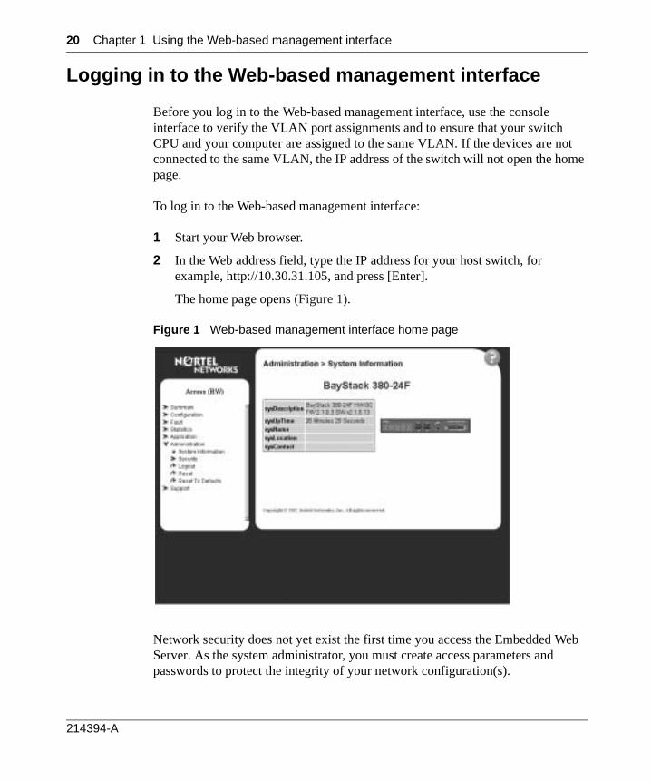
Logging in to the Web-based management interface
Before you log in to the Web-based management interface, use the console interface to verify the VLAN port assignments and to ensure that your switch CPU and your computer are assigned to the same VLAN. If the devices are not connected to the same VLAN, the IP address of the switch will not open the home page.
To log in to the Web-based management interface:
1 Start your Web browser.
2 In the Web address field, type the IP address for your host switch, for example, http://10.30.31.105, and press [Enter].
The home page opens (Figure 1).
Figure 1 Web-based management interface home page
Network security does not yet exist the first time you access the Embedded Web Server. As the system administrator, you must create access parameters and passwords to protect the integrity of your network configuration(s).
214394-A
Chapter 1 Using the Web-based management interface 21
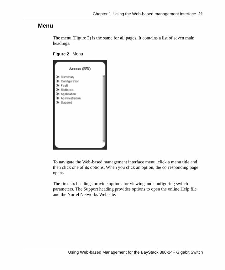
Menu
The menu (Figure 2) is the same for all pages. It contains a list of seven main headings.
Figure 2 Menu
To navigate the Web-based management interface menu, click a menu title and then click one of its options. When you click an option, the corresponding page opens.
The first six headings provide options for viewing and configuring switch parameters. The Support heading provides options to open the online Help file and the Nortel Networks Web site.
Using Web-based Management for the BayStack 380-24F Gigabit Switch
22 Chapter 1 Using the Web-based management interface
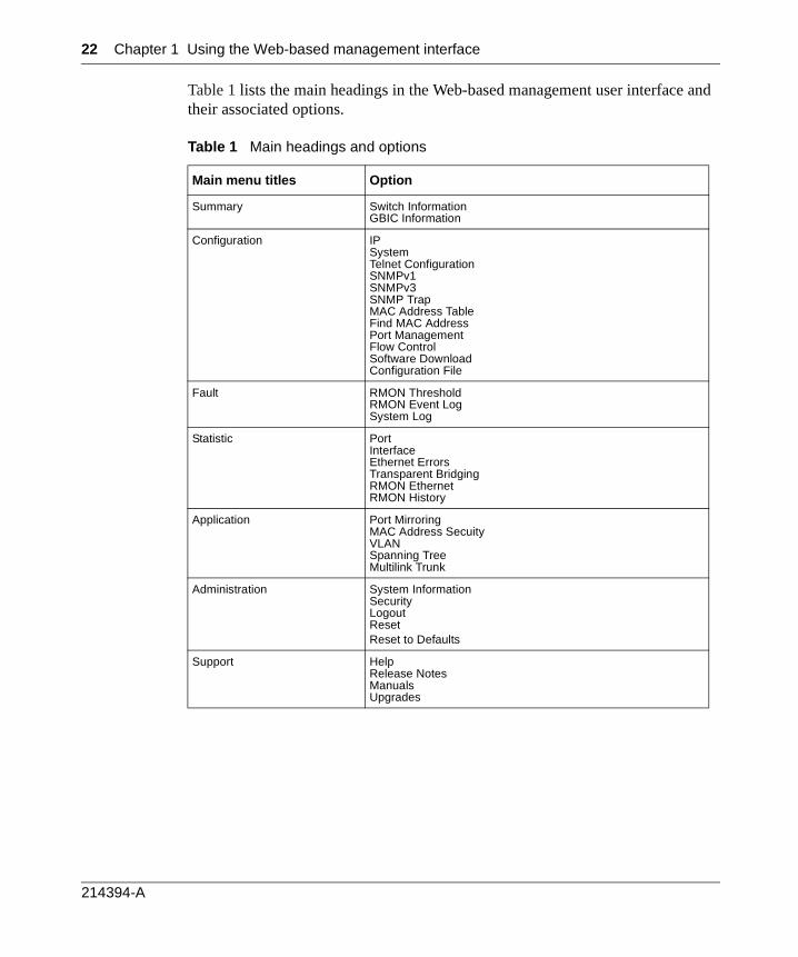
Table 1 lists the main headings in the Web-based management user interface and their associated options.
Table 1 Main headings and options
Main menu titles Option
Summary Switch InformationGBIC Information
Configuration IPSystemTelnet ConfigurationSNMPv1SNMPv3SNMP TrapMAC Address TableFind MAC AddressPort ManagementFlow ControlSoftware DownloadConfiguration File
Fault RMON ThresholdRMON Event LogSystem Log
Statistic PortInterfaceEthernet ErrorsTransparent BridgingRMON EthernetRMON History
Application Port MirroringMAC Address SecuityVLANSpanning TreeMultilink Trunk
Administration System InformationSecurityLogoutResetReset to Defaults
Support HelpRelease NotesManualsUpgrades
214394-A
Chapter 1 Using the Web-based management interface 23
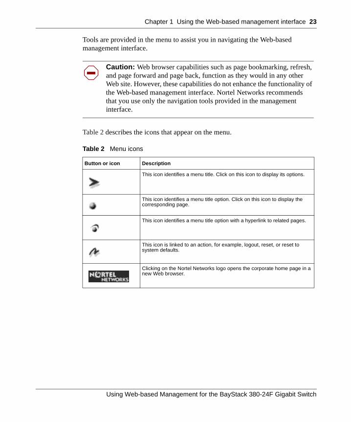
Tools are provided in the menu to assist you in navigating the Web-based management interface.
Table 2 describes the icons that appear on the menu.
Caution: Web browser capabilities such as page bookmarking, refresh, and page forward and page back, function as they would in any other Web site. However, these capabilities do not enhance the functionality of the Web-based management interface. Nortel Networks recommends that you use only the navigation tools provided in the management interface.
Table 2 Menu icons
Button or icon Description
This icon identifies a menu title. Click on this icon to display its options.
This icon identifies a menu title option. Click on this icon to display the corresponding page.
This icon identifies a menu title option with a hyperlink to related pages.
This icon is linked to an action, for example, logout, reset, or reset to system defaults.
Clicking on the Nortel Networks logo opens the corporate home page in a new Web browser.
Using Web-based Management for the BayStack 380-24F Gigabit Switch
24 Chapter 1 Using the Web-based management interface
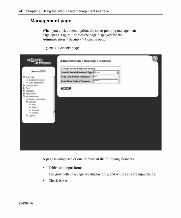
Management page
When you click a menu option, the corresponding management page opens. Figure 3 shows the page displayed for the Administration > Security > Console option.
Figure 3 Console page
A page is composed of one or more of the following elements:
• Tables and input forms
The gray cells in a page are display only, and white cells are input fields.
• Check boxes
214394-A
Chapter 1 Using the Web-based management interface 25
You enable or disable a selection by clicking a check box. When a check mark is displayed in the box, that selection is enabled. You disable a selection by clicking the checked box.
• Icons and buttons
Icons and buttons perform an action concerning the displayed page or the switch. Some pages include a button that opens another page or updates the values shown on the current page. Other pages include icons that initiate an action, such as reformatting the current displayed data as a bar or pie chart.
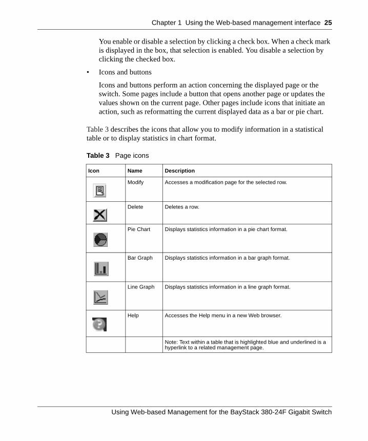
Table 3 describes the icons that allow you to modify information in a statistical table or to display statistics in chart format.
Table 3 Page icons
Icon Name Description
Modify Accesses a modification page for the selected row.
Delete Deletes a row.
Pie Chart Displays statistics information in a pie chart format.
Bar Graph Displays statistics information in a bar graph format.
Line Graph Displays statistics information in a line graph format.
Help Accesses the Help menu in a new Web browser.
Note: Text within a table that is highlighted blue and underlined is a hyperlink to a related management page.
Using Web-based Management for the BayStack 380-24F Gigabit Switch

26 Chapter 1 Using the Web-based management interface
214394-A
27
Chapter 2Administering the switch
The administrative options available to you are:
• “Viewing system information”, (next)
• “Configuring system security” on page 29
• “Accessing the management interface” on page 32
• “Resetting the BayStack 380-24F Gigabit Switch” on page 34
• “Changing the BayStack 380-24F Gigabit Switch to system defaults” on page 34
• “Logging out of the management interface” on page 35
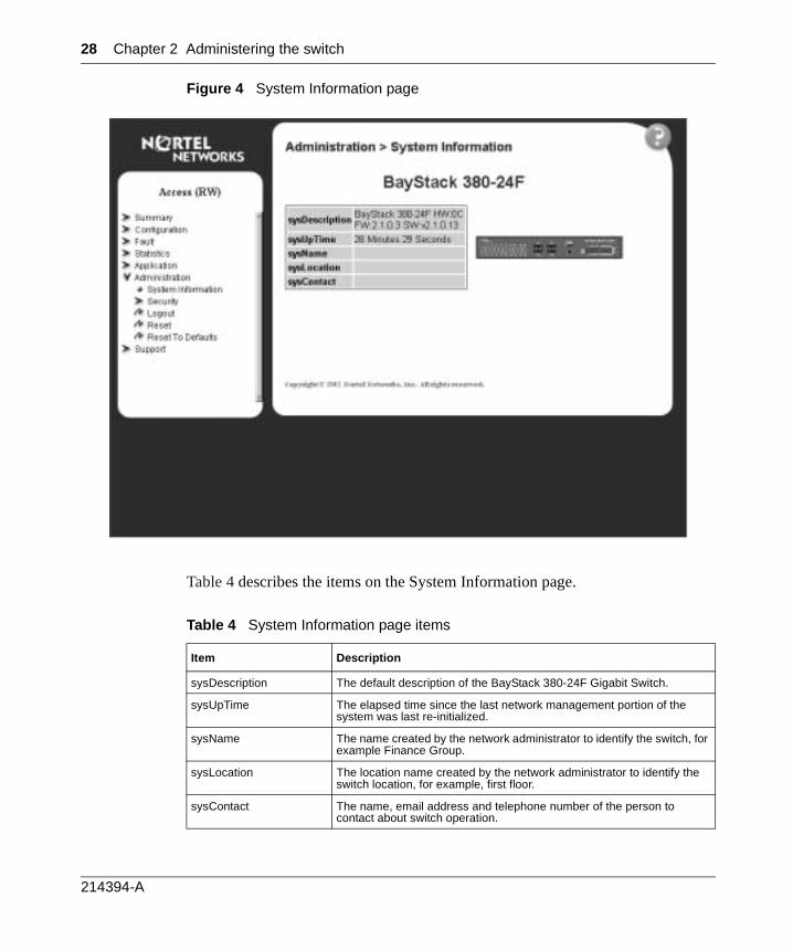
Viewing system information
You can view an image of the BayStack 380-24F Gigabit switch configuration, information about the host device, and, if provided, the contact person or manager for the switch. The System Information page is also the Web-based management interface home page.
To view system information:
The System Information page opens (Figure 4).
From the main menu, choose Administration > System Information.
Note: You may create or modify existing system information parameters using the System page. For more information on configuring system information, see “Modifying system settings” on page 44.
Using Web-based Management for the BayStack 380-24F Gigabit Switch
28 Chapter 2 Administering the switch
Figure 4 System Information page
Table 4 describes the items on the System Information page.
Table 4 System Information page items
Item Description
sysDescription The default description of the BayStack 380-24F Gigabit Switch.
sysUpTime The elapsed time since the last network management portion of the system was last re-initialized.
sysName The name created by the network administrator to identify the switch, for example Finance Group.
sysLocation The location name created by the network administrator to identify the switch location, for example, first floor.
sysContact The name, email address and telephone number of the person to contact about switch operation.
214394-A

Chapter 2 Administering the switch 29
Configuring system security
This section describes the steps you use to build and manage security using the Web-based management interface.
Setting console, Telnet, and Web passwords
To set console, Telnet, and Web passwords:
1 From the main menu, choose Administration > Security and Console, Telnet, or Web.
The selected password page opens (Figure 5).
Figure 5 Console password setting page
Note: The title of the page corresponds to the menu selectionyou choose. In Figure 5, the network administrator selected Administration > Security > Console.
Using Web-based Management for the BayStack 380-24F Gigabit Switch
30 Chapter 2 Administering the switch
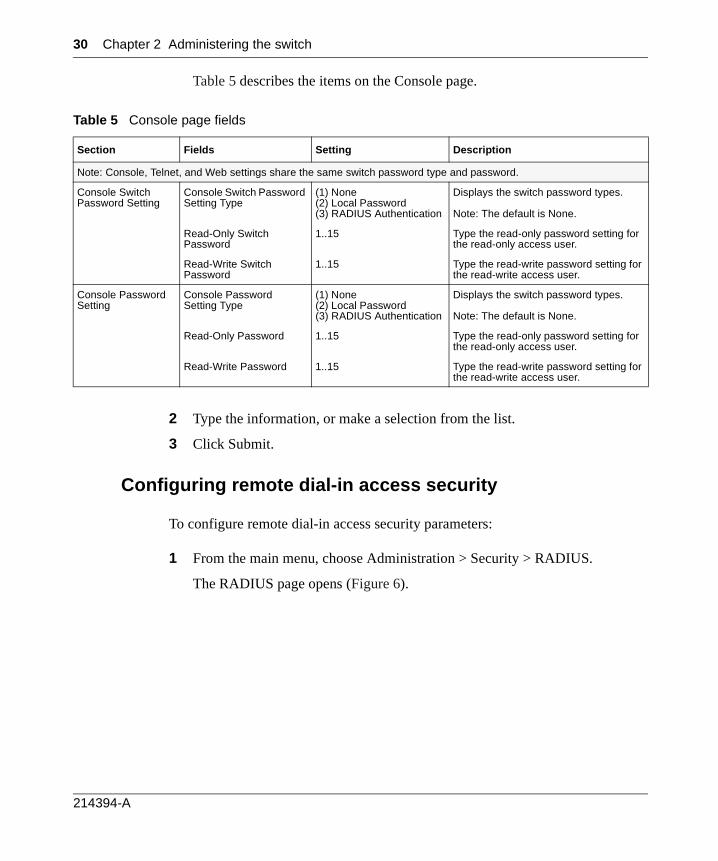
Table 5 describes the items on the Console page.
2 Type the information, or make a selection from the list.
3 Click Submit.
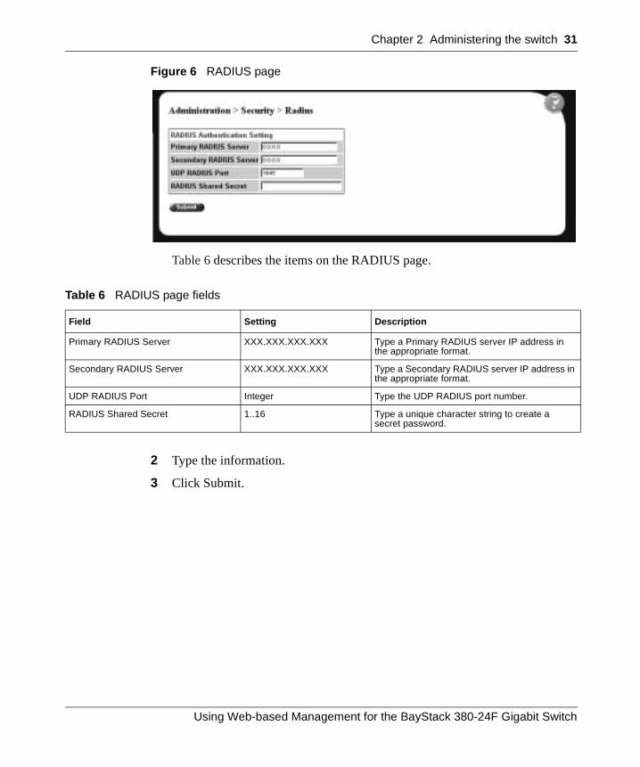
Configuring remote dial-in access security
To configure remote dial-in access security parameters:
1 From the main menu, choose Administration > Security > RADIUS.
The RADIUS page opens (Figure 6).
Table 5 Console page fields
Section Fields Setting Description
Note: Console, Telnet, and Web settings share the same switch password type and password.
Console Switch Password Setting
Console Switch Password Setting Type
(1) None(2) Local Password(3) RADIUS Authentication
Displays the switch password types.
Note: The default is None.
Read-Only Switch Password
1..15 Type the read-only password setting for the read-only access user.
Read-Write Switch Password
1..15 Type the read-write password setting for the read-write access user.
Console Password Setting
Console Password Setting Type
(1) None(2) Local Password(3) RADIUS Authentication
Displays the switch password types.
Note: The default is None.
Read-Only Password 1..15 Type the read-only password setting for the read-only access user.
Read-Write Password 1..15 Type the read-write password setting for the read-write access user.
214394-A
Chapter 2 Administering the switch 31
Figure 6 RADIUS page
Table 6 describes the items on the RADIUS page.
2 Type the information.
3 Click Submit.
Table 6 RADIUS page fields
Field Setting Description
Primary RADIUS Server XXX.XXX.XXX.XXX Type a Primary RADIUS server IP address in the appropriate format.
Secondary RADIUS Server XXX.XXX.XXX.XXX Type a Secondary RADIUS server IP address in the appropriate format.
UDP RADIUS Port Integer Type the UDP RADIUS port number.
RADIUS Shared Secret 1..16 Type a unique character string to create a secret password.
Using Web-based Management for the BayStack 380-24F Gigabit Switch

32 Chapter 2 Administering the switch
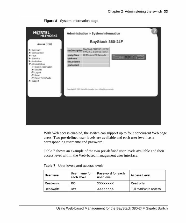
Accessing the management interface
Once switch passwords and RADIUS authentication settings are integrated into the Web-based management user interface, anyone who attempts to use the application is presented with a log on page (Figure 7).
Figure 7 Web-based management interface log on page
To log on to the Web-based management interface:
1 In the Username text box, type RO (upper-case) for read-only access or RW (upper-case) for read-write access.
2 In the Password text box, type your password.
3 Click Log On.
The System Information page opens (Figure 8).
214394-A
Chapter 2 Administering the switch 33
Figure 8 System Information page
With Web access enabled, the switch can support up to four concurrent Web page users. Two pre-defined user levels are available and each user level has a corresponding username and password.
Table 7 shows an example of the two pre-defined user levels available and their access level within the Web-based management user interface.
Table 7 User levels and access levels
User levelUser name for each level
Password for each user level
Access Level
Read-only RO XXXXXXXX Read only
Read/write RW XXXXXXXX Full read/write access
Using Web-based Management for the BayStack 380-24F Gigabit Switch
34 Chapter 2 Administering the switch
Resetting the BayStack 380-24F Gigabit Switch
You can reboot a BayStack 380-24F switch without erasing any configured switch parameters. While rebooting, the switch initiates a self-test that comprises various diagnostic routines and subtests. The LEDs display various patterns to indicate that the subtests are in progress.
To reboot the BayStack 380-24F Gigabit Switch without making changes (since your last Submit request):
1 From the main menu, choose Administration > Reset.
The system prompts you to select ok to reset the switch or cancel.
2 Click ok to reset the switch.
Changing the BayStack 380-24F Gigabit Switch to system defaults
You can change a switch and replace all configured switch parameters with the factory default values.
During the process of changing to default settings, the switch initiates a self-test that comprises various diagnostic routines and subtests. The LEDs display various patterns to indicate that the subtests are in progress.
To change the BayStack 380-24F Gigabit Switch to system defaults:
1 From the main menu, choose Administration > Reset to Default.
The system prompts you select Ok to reset the switch to the system defaults or cancel.
2 Click Ok to reset to system defaults.
Caution: If you choose change to default settings, all configured settings are replaced with factory default settings when you click Submit. For more information on factory default settings, see Using the BayStack 380-24F Gigabit Switch (214391-A).
214394-A
Chapter 2 Administering the switch 35
Logging out of the management interface
To log out of the Web-based management user interface:
1 From the main menu, choose Administration > Logout.
A message opens prompting you to confirm your request
2 Do one of the following:
• Click OK to log out.
• Click Cancel to return to the Web-based management interface home page.
Using Web-based Management for the BayStack 380-24F Gigabit Switch

36 Chapter 2 Administering the switch
214394-A
37
Chapter 3Viewing summary information
The summary information options are:
• “Viewing information,” (next)
• “Viewing GBIC information” on page 39
Viewing information
You can view a summary of your switch framework, for example, the current version of the running software and the IP address of the Web-based management interface.
To view switch information:
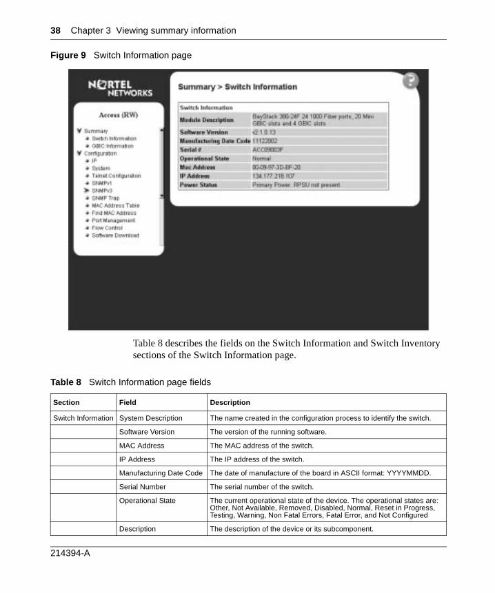
1 From the main menu, choose Summary > Switch Information.
The Switch Information page opens (Figure 9).
Note: The Web-based management user interface automatically detects the operational mode of your system.
Using Web-based Management for the BayStack 380-24F Gigabit Switch
38 Chapter 3 Viewing summary information
Figure 9 Switch Information page
Table 8 describes the fields on the Switch Information and Switch Inventory sections of the Switch Information page.
Table 8 Switch Information page fields
Section Field Description
Switch Information System Description The name created in the configuration process to identify the switch.
Software Version The version of the running software.
MAC Address The MAC address of the switch.
IP Address The IP address of the switch.
Manufacturing Date Code The date of manufacture of the board in ASCII format: YYYYMMDD.
Serial Number The serial number of the switch.
Operational State The current operational state of the device. The operational states are: Other, Not Available, Removed, Disabled, Normal, Reset in Progress, Testing, Warning, Non Fatal Errors, Fatal Error, and Not Configured
Description The description of the device or its subcomponent.
214394-A
Chapter 3 Viewing summary information 39
2 In the upper-left corner of the Switch Information page, click the number of the device you want to view.
The Switch Information page is updated with information about the selected switch.
Viewing GBIC information
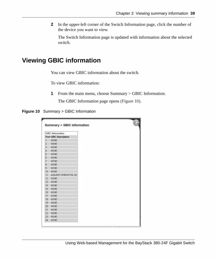
You can view GBIC information about the switch.
To view GBIC information:
1 From the main menu, choose Summary > GBIC Information.
The GBIC Information page opens (Figure 10).
Figure 10 Summary > GBIC Information
Using Web-based Management for the BayStack 380-24F Gigabit Switch

40 Chapter 3 Viewing summary information
Table 9 describes the fields on the GBIC Information page.
Table 9 GBIC Information page fields
Item Description
Port Specifies the number of the GBIC port.
GBIC Description Specifies the type of GBIC
214394-A
41
Chapter 4Configuring the switch
The switch configuration options available to you are:
• “Configuring BootP, IP, and gateway settings”, (next)
• “Modifying system settings” on page 44
• “About SNMP” on page 49
• “Configuring SNMPv1” on page 49
• “Configuring SNMPv3” on page 51
• “Viewing learned MAC addresses by VLAN” on page 71
• “Viewing learned MAC addresses by VLAN” on page 71
• “Configuring switch port autonegotiation speed” on page 74
• “Configuring flow control” on page 75
• “Downloading switch images” on page 77
• “Storing or retrieving a configuration file from a TFTP server” on page 80
• “Configuring port communication speed” on page 83
Note: In order to use all the BayStack 380-24F Gigabit Switch management features, you must connect your management station into a BayStack 380-24F Gigabit Switch port.
Using Web-based Management for the BayStack 380-24F Gigabit Switch
42 Chapter 4 Configuring the switch
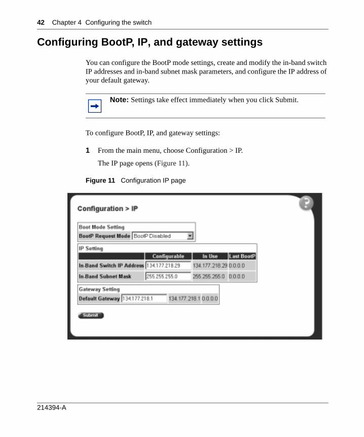
Configuring BootP, IP, and gateway settings
You can configure the BootP mode settings, create and modify the in-band switch IP addresses and in-band subnet mask parameters, and configure the IP address of your default gateway.
To configure BootP, IP, and gateway settings:
1 From the main menu, choose Configuration > IP.
The IP page opens (Figure 11).
Figure 11 Configuration IP page
Note: Settings take effect immediately when you click Submit.
214394-A
Chapter 4 Configuring the switch 43
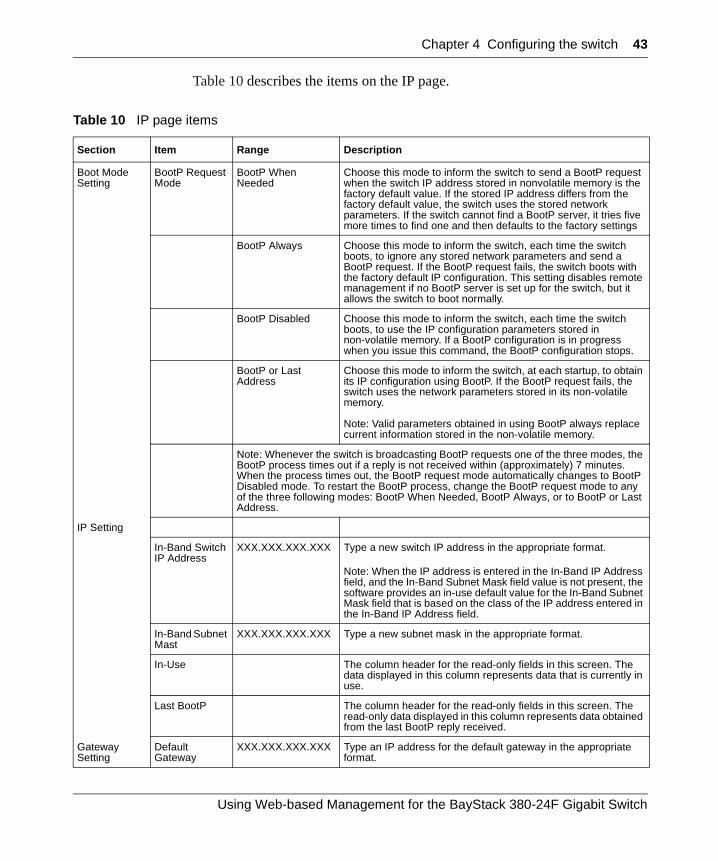
Table 10 describes the items on the IP page.
Table 10 IP page items
Section Item Range Description
Boot Mode Setting
BootP Request Mode
BootP When Needed
Choose this mode to inform the switch to send a BootP request when the switch IP address stored in nonvolatile memory is the factory default value. If the stored IP address differs from the factory default value, the switch uses the stored network parameters. If the switch cannot find a BootP server, it tries five more times to find one and then defaults to the factory settings
BootP Always Choose this mode to inform the switch, each time the switch boots, to ignore any stored network parameters and send a BootP request. If the BootP request fails, the switch boots with the factory default IP configuration. This setting disables remote management if no BootP server is set up for the switch, but it allows the switch to boot normally.
BootP Disabled Choose this mode to inform the switch, each time the switch boots, to use the IP configuration parameters stored in non-volatile memory. If a BootP configuration is in progress when you issue this command, the BootP configuration stops.
BootP or Last Address
Choose this mode to inform the switch, at each startup, to obtain its IP configuration using BootP. If the BootP request fails, the switch uses the network parameters stored in its non-volatile memory.
Note: Valid parameters obtained in using BootP always replace current information stored in the non-volatile memory.
Note: Whenever the switch is broadcasting BootP requests one of the three modes, the BootP process times out if a reply is not received within (approximately) 7 minutes. When the process times out, the BootP request mode automatically changes to BootP Disabled mode. To restart the BootP process, change the BootP request mode to any of the three following modes: BootP When Needed, BootP Always, or to BootP or Last Address.
IP Setting
In-Band Switch IP Address
XXX.XXX.XXX.XXX Type a new switch IP address in the appropriate format.
Note: When the IP address is entered in the In-Band IP Address field, and the In-Band Subnet Mask field value is not present, the software provides an in-use default value for the In-Band Subnet Mask field that is based on the class of the IP address entered in the In-Band IP Address field.
In-Band Subnet Mast
XXX.XXX.XXX.XXX Type a new subnet mask in the appropriate format.
In-Use The column header for the read-only fields in this screen. The data displayed in this column represents data that is currently in use.
Last BootP The column header for the read-only fields in this screen. The read-only data displayed in this column represents data obtained from the last BootP reply received.
Gateway Setting
Default Gateway
XXX.XXX.XXX.XXX Type an IP address for the default gateway in the appropriate format.
Using Web-based Management for the BayStack 380-24F Gigabit Switch
44 Chapter 4 Configuring the switch
2 Type information in the text boxes, or select from a list.
3 Click Submit.
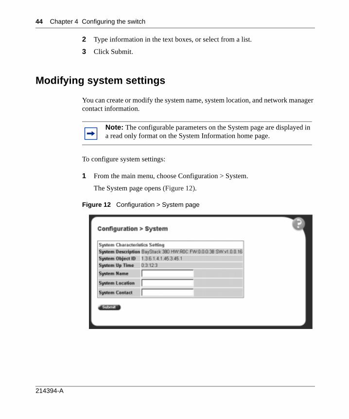
Modifying system settings
You can create or modify the system name, system location, and network manager contact information.
To configure system settings:
1 From the main menu, choose Configuration > System.
The System page opens (Figure 12).
Figure 12 Configuration > System page
Note: The configurable parameters on the System page are displayed in a read only format on the System Information home page.
214394-A
Chapter 4 Configuring the switch 45
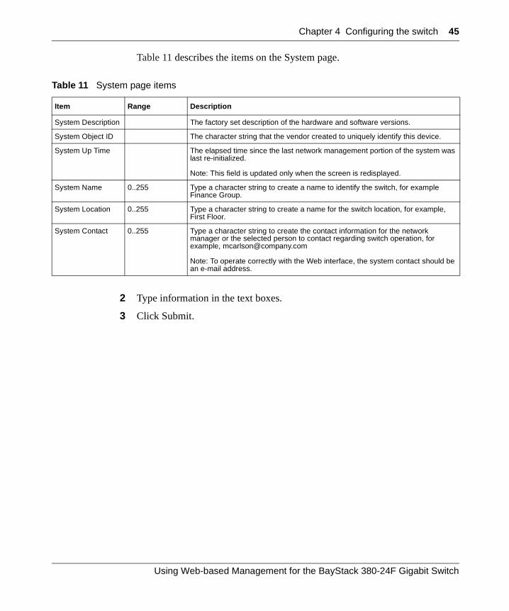
Table 11 describes the items on the System page.
2 Type information in the text boxes.
3 Click Submit.
Table 11 System page items
Item Range Description
System Description The factory set description of the hardware and software versions.
System Object ID The character string that the vendor created to uniquely identify this device.
System Up Time The elapsed time since the last network management portion of the system was last re-initialized.
Note: This field is updated only when the screen is redisplayed.
System Name 0..255 Type a character string to create a name to identify the switch, for example Finance Group.
System Location 0..255 Type a character string to create a name for the switch location, for example, First Floor.
System Contact 0..255 Type a character string to create the contact information for the network manager or the selected person to contact regarding switch operation, for example, [email protected]
Note: To operate correctly with the Web interface, the system contact should be an e-mail address.
Using Web-based Management for the BayStack 380-24F Gigabit Switch
46 Chapter 4 Configuring the switch
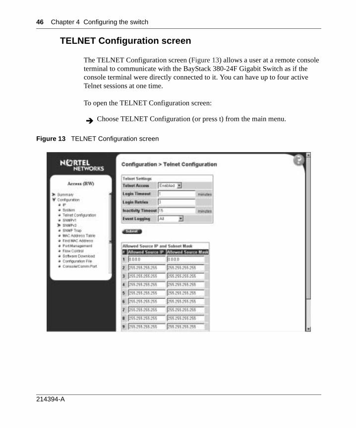
TELNET Configuration screen
The TELNET Configuration screen (Figure 13) allows a user at a remote console terminal to communicate with the BayStack 380-24F Gigabit Switch as if the console terminal were directly connected to it. You can have up to four active Telnet sessions at one time.
To open the TELNET Configuration screen:
Figure 13 TELNET Configuration screen
Choose TELNET Configuration (or press t) from the main menu.
214394-A
Chapter 4 Configuring the switch 47
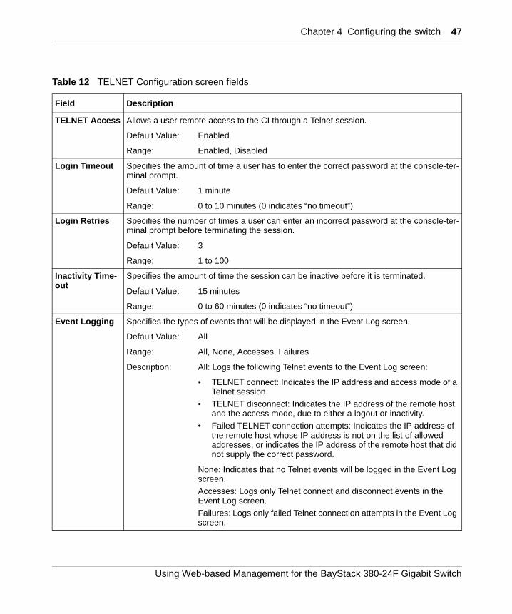
Table 12 TELNET Configuration screen fields
Field Description
TELNET Access Allows a user remote access to the CI through a Telnet session.
Default Value: Enabled
Range: Enabled, Disabled
Login Timeout Specifies the amount of time a user has to enter the correct password at the console-ter-minal prompt.
Default Value: 1 minute
Range: 0 to 10 minutes (0 indicates “no timeout”)
Login Retries Specifies the number of times a user can enter an incorrect password at the console-ter-minal prompt before terminating the session.
Default Value: 3
Range: 1 to 100
Inactivity Time-out
Specifies the amount of time the session can be inactive before it is terminated.
Default Value: 15 minutes
Range: 0 to 60 minutes (0 indicates “no timeout”)
Event Logging Specifies the types of events that will be displayed in the Event Log screen.
Default Value: All
Range: All, None, Accesses, Failures
Description: All: Logs the following Telnet events to the Event Log screen:
• TELNET connect: Indicates the IP address and access mode of a Telnet session.
• TELNET disconnect: Indicates the IP address of the remote host and the access mode, due to either a logout or inactivity.
• Failed TELNET connection attempts: Indicates the IP address of the remote host whose IP address is not on the list of allowed addresses, or indicates the IP address of the remote host that did not supply the correct password.
None: Indicates that no Telnet events will be logged in the Event Log screen.Accesses: Logs only Telnet connect and disconnect events in the Event Log screen.Failures: Logs only failed Telnet connection attempts in the Event Log screen.
Using Web-based Management for the BayStack 380-24F Gigabit Switch
48 Chapter 4 Configuring the switch
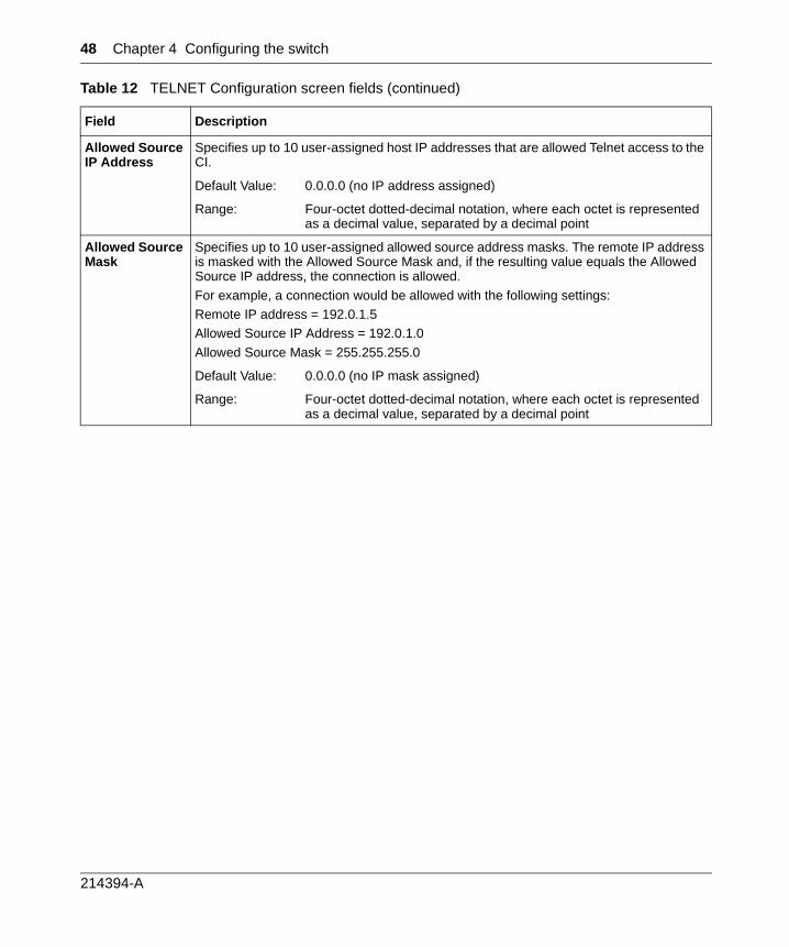
Allowed Source IP Address
Specifies up to 10 user-assigned host IP addresses that are allowed Telnet access to the CI.
Default Value: 0.0.0.0 (no IP address assigned)
Range: Four-octet dotted-decimal notation, where each octet is represented as a decimal value, separated by a decimal point
Allowed Source Mask
Specifies up to 10 user-assigned allowed source address masks. The remote IP address is masked with the Allowed Source Mask and, if the resulting value equals the Allowed Source IP address, the connection is allowed.
For example, a connection would be allowed with the following settings:Remote IP address = 192.0.1.5Allowed Source IP Address = 192.0.1.0
Allowed Source Mask = 255.255.255.0
Default Value: 0.0.0.0 (no IP mask assigned)
Range: Four-octet dotted-decimal notation, where each octet is represented as a decimal value, separated by a decimal point
Table 12 TELNET Configuration screen fields (continued)
Field Description
214394-A
Chapter 4 Configuring the switch 49
About SNMP
Simple Network Management Protocol (SNMP) is the standard for network management that uses a common software agent to manage local and wide area network equipment from different vendors; part of the Transmission Control Protocol/Internet Protocol (TCP/IP) suite and defined in RFC1157. SNMPv1 is version one, or the original standard protocol. SNMPv3 is a combination of proposal updates to SNMP, most of which deal with security.
Configuring SNMPv1
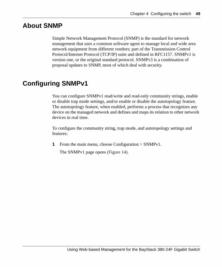
You can configure SNMPv1 read/write and read-only community strings, enable or disable trap mode settings, and/or enable or disable the autotopology feature. The autotopology feature, when enabled, performs a process that recognizes any device on the managed network and defines and maps its relation to other network devices in real time.
To configure the community string, trap mode, and autotopology settings and features:
1 From the main menu, choose Configuration > SNMPv1.
The SNMPv1 page opens (Figure 14).
Using Web-based Management for the BayStack 380-24F Gigabit Switch
50 Chapter 4 Configuring the switch
Figure 14 SNMPv1 page
Table 13 describes the items on the SNMPv1 page.
2 Type information in the text boxes, or select from a list.
3 Click Submit in any section to save your changes.
Table 13 SNMPv1 page items
Section Item Range Description
Community String Setting
Read-Only Community String
1..32 Type a character string to identify the community string for the SNMPv1 read-only community, for example, public or private.
The default value is public.
Read-Write Community String
1..32 Type a character string to identify the community string for the SNMPv1 read-write community, for example, public or private.
The default value is private.
Trap Mode Setting
Authentication Trap
(1) Enable(2) Disable
Choose to enable or disable the authentication trap.
AutoTopology Setting
AutoTopology (1) Enable(2) Disable
Choose to enable or disable the autotopology feature.
214394-A
Chapter 4 Configuring the switch 51
Configuring SNMPv3
This section describes the steps to build and manage SNMPv3 in the Web-based management user interface.
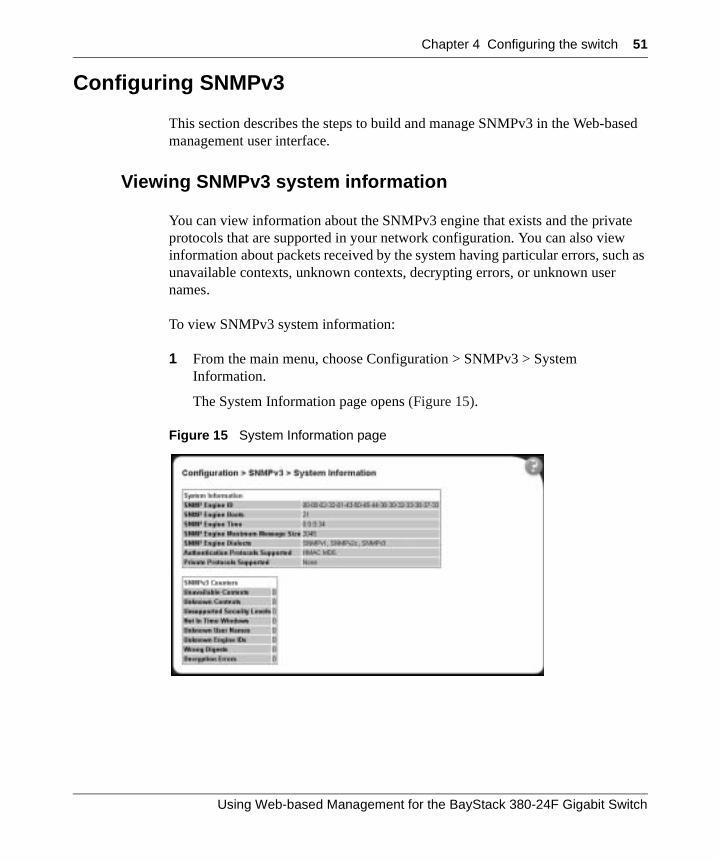
Viewing SNMPv3 system information
You can view information about the SNMPv3 engine that exists and the private protocols that are supported in your network configuration. You can also view information about packets received by the system having particular errors, such as unavailable contexts, unknown contexts, decrypting errors, or unknown user names.
To view SNMPv3 system information:
1 From the main menu, choose Configuration > SNMPv3 > System Information.
The System Information page opens (Figure 15).
Figure 15 System Information page
Using Web-based Management for the BayStack 380-24F Gigabit Switch
52 Chapter 4 Configuring the switch
Table 14 describes the fields on the System Information section of the SNMPv3 System Information page.
Table 15 describes the fields on the SNMPv3 Counters section of the SNMPv3 System Information page.
Table 14 System Information section fields
Item Description
SNMP Engine ID The SNMP engine’s identification number.
SNMP Engine Boots The number of times that the SNMP engine has re-initialized itself since its initial configuration.
SNMP Engine Time The number of seconds since the SNMP engine last incremented the snmpEngineBoots object.
SNMP Engine Maximum Message Size
The maximum length, in octets, of an SNMP message which this SNMP engine can send or receive and process determined as the minimum of the maximum message size values supported among all transports available to and supported by the engine.
SNMP Engine Dialects The SNMP dialect the engine recognizes. The dialects are:SNMP1v1, SNMPv2C, and SNMPv3.
Authentication Protocols Supported
The registration point for standards-track authentication protocols used in SNMP Management Frameworks. The registration points are: None, HMAC MD5, HMAC SHA, HMAC MD5.
Note: The BayStack 380-24F Gigabit Switch supports only the MD5 authentication protocol.
Private Protocols Supported
The registration point for standards-track privacy protocols used in SNMP Management Frameworks. The registration points are: None or CBC-DES.
Note: The BayStack 380-24F Gigabit Switch does not support privacy protocols.
Table 15 SNMPv3 Counters section fields
Item Description
Unavailable Contexts The total number of packets dropped by the SNMP engine because the context containedin the message was unavailable.
Unknown Contexts The total number of packets dropped by the SNMP engine because the context containedin the message was unknown.
Unsupported Security Levels
The total number of packets dropped by the SNMP engine because they requested a security level that was unknown to the SNMP engine or otherwise unavailable.
Not in Time Windows The total number of packets dropped by the SNMP engine because they appeared outside of the authoritative SNMP engine’s window.
Unknown User Names The total number of packets dropped by the SNMP engine because they referenced an unknown user.
Unknown Engine IDs The total number of packets dropped by the SNMP engine because they referenced an snmpEngineID that was not known to the SNMP engine.
214394-A
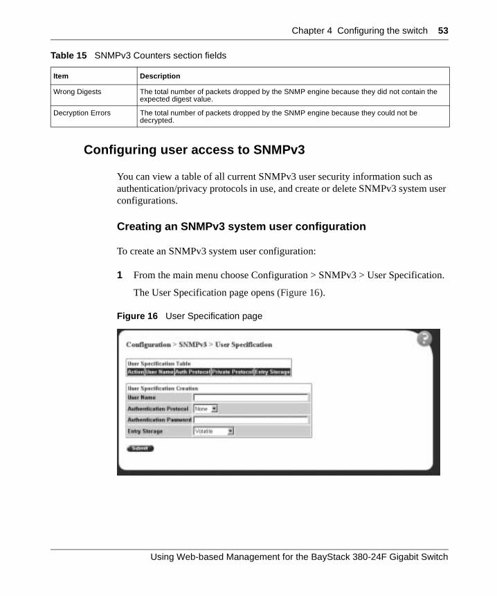
Chapter 4 Configuring the switch 53
Configuring user access to SNMPv3
You can view a table of all current SNMPv3 user security information such as authentication/privacy protocols in use, and create or delete SNMPv3 system user configurations.
Creating an SNMPv3 system user configuration
To create an SNMPv3 system user configuration:
1 From the main menu choose Configuration > SNMPv3 > User Specification.
The User Specification page opens (Figure 16).
Figure 16 User Specification page
Wrong Digests The total number of packets dropped by the SNMP engine because they did not contain the expected digest value.
Decryption Errors The total number of packets dropped by the SNMP engine because they could not be decrypted.
Table 15 SNMPv3 Counters section fields
Item Description
Using Web-based Management for the BayStack 380-24F Gigabit Switch
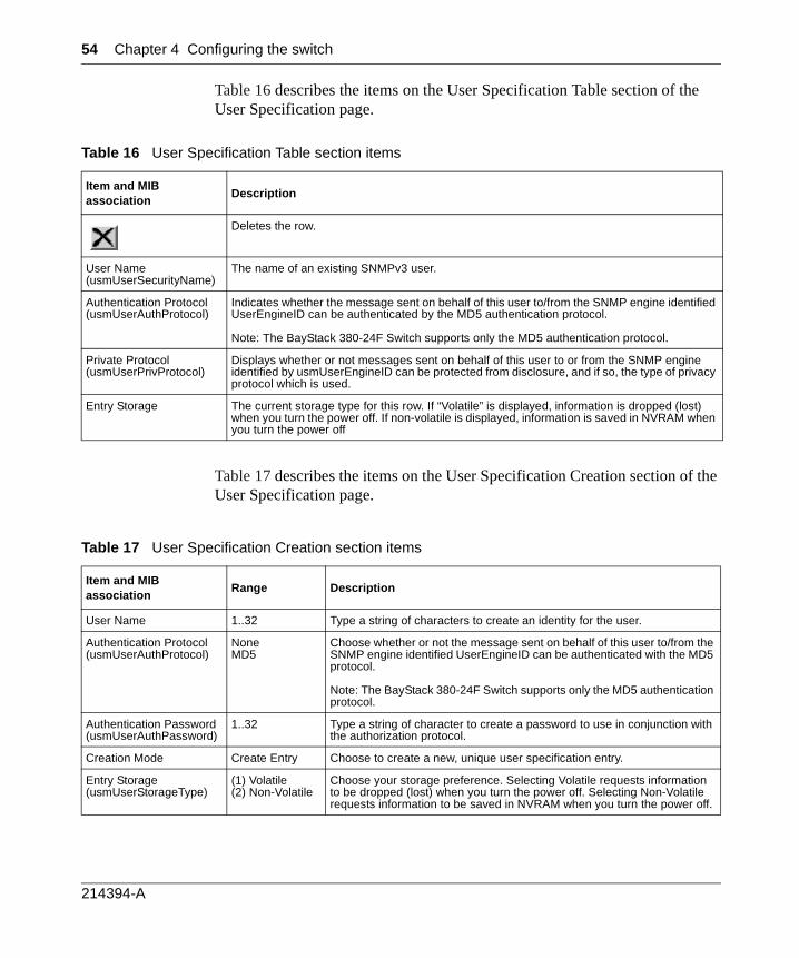
54 Chapter 4 Configuring the switch
Table 16 describes the items on the User Specification Table section of the User Specification page.
Table 17 describes the items on the User Specification Creation section of the User Specification page.
Table 16 User Specification Table section items
Item and MIB association
Description
Deletes the row.
User Name(usmUserSecurityName)
The name of an existing SNMPv3 user.
Authentication Protocol(usmUserAuthProtocol)
Indicates whether the message sent on behalf of this user to/from the SNMP engine identified UserEngineID can be authenticated by the MD5 authentication protocol.
Note: The BayStack 380-24F Switch supports only the MD5 authentication protocol.
Private Protocol(usmUserPrivProtocol)
Displays whether or not messages sent on behalf of this user to or from the SNMP engine identified by usmUserEngineID can be protected from disclosure, and if so, the type of privacy protocol which is used.
Entry Storage The current storage type for this row. If “Volatile” is displayed, information is dropped (lost) when you turn the power off. If non-volatile is displayed, information is saved in NVRAM when you turn the power off
Table 17 User Specification Creation section items
Item and MIB association
Range Description
User Name 1..32 Type a string of characters to create an identity for the user.
Authentication Protocol(usmUserAuthProtocol)
NoneMD5
Choose whether or not the message sent on behalf of this user to/from the SNMP engine identified UserEngineID can be authenticated with the MD5 protocol.
Note: The BayStack 380-24F Switch supports only the MD5 authentication protocol.
Authentication Password(usmUserAuthPassword)
1..32 Type a string of character to create a password to use in conjunction with the authorization protocol.
Creation Mode Create Entry Choose to create a new, unique user specification entry.
Entry Storage(usmUserStorageType)
(1) Volatile(2) Non-Volatile
Choose your storage preference. Selecting Volatile requests information to be dropped (lost) when you turn the power off. Selecting Non-Volatile requests information to be saved in NVRAM when you turn the power off.
214394-A
Chapter 4 Configuring the switch 55
2 In the User Specification Creation section, type information in the text boxes, or select from a list.
3 Click Submit.
The new configuration is displayed in the User Specification Table (Figure 16 on page 53).
Deleting an SNMPv3 system user configuration
To delete an existing SNMPv3 user configuration:
1 From the main menu, choose Configuration > SNMPv3 > User Specification.
The User Specification page opens (Figure 16 on page 53.)
2 In the User Specification Table, click the Delete icon for the entry you want to delete.
A message opens prompting you to confirm your request.
3 Do one of the following:
• Click Yes to delete the SNMPv3 user configuration.
• Click Cancel to return to the User Specification page without making changes.
Using Web-based Management for the BayStack 380-24F Gigabit Switch
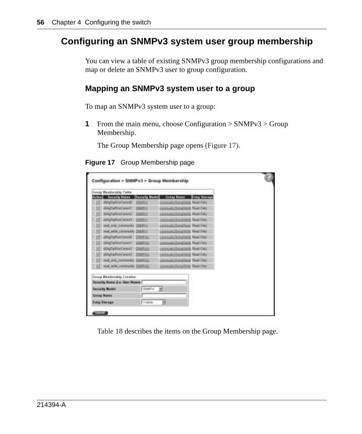
56 Chapter 4 Configuring the switch
Configuring an SNMPv3 system user group membership
You can view a table of existing SNMPv3 group membership configurations and map or delete an SNMPv3 user to group configuration.
Mapping an SNMPv3 system user to a group
To map an SNMPv3 system user to a group:
1 From the main menu, choose Configuration > SNMPv3 > Group Membership.
The Group Membership page opens (Figure 17).
Figure 17 Group Membership page
Table 18 describes the items on the Group Membership page.
214394-A

Chapter 4 Configuring the switch 57
2 In the Group Membership Creation section, type information in the text boxes, or select from a list.
3 Click Submit.
The new entry is displayed in the Group Membership Table (Figure 17 on page 56).
Deleting an SNMPv3 group membership configuration
To delete an SNMPv3 group membership configuration:
1 From the main menu, choose Configuration > SNMPv3 > Group Membership.
The Group Membership page opens (Figure 17 on page 56).
2 In the Group Membership Table, click the Delete icon for the entry you want to delete.
A message opens prompting you to confirm your request.
Table 18 Group Membership page items
Item and MIB association Range Description
Deletes the row.
Security Name(vacmSecurityToGroupStatus)
1..32 Type a string of character to create a security name for the principal which is mapped by this entry to a group name.
Security Model(vacmSecurityToGroupStatus)
(1) SNMPv1(2) SNMPv2c(3) USM
Choose the security model within which the security name to group name mapping is valid.
Group Name(vacmGroupName)
1..32 Type a string of character to specify the group name.
Entry Storage(vacmSecurityToGroupStorageType)
(1) Volatile(2) Non-Volatile
Choose your storage preference. Selecting Volatile requests information to be dropped (lost) when you turn the power off. Selecting Non-Volatile requests information to be saved in NVRAM when you turn the power off.
Using Web-based Management for the BayStack 380-24F Gigabit Switch
58 Chapter 4 Configuring the switch
3 Do one of the following:
• Click Yes to delete the group membership configuration.
• Click Cancel to return to the Group Membership page without making changes.
Configuring SNMPv3 group access rights
You can view a table of existing SNMPv3 group access rights configurations, and you can create or delete a group’s SNMPv3 system-level access rights.
Creating an SNMPv3 group access rights configuration
To create a group’s SNMPv3 system-level access right configuration:
1 From the main menu, choose Configuration > SNMPv3 > Group Access Rights.
The Group Access Rights page opens (Figure 18).
Note: This Group Membership Table section of the Group Membership page contains hyperlinks to the SNMPv3 User Specification and Group Access Rights pages. For more information on these pages, see “Configuring user access to SNMPv3” on page 53 and “Configuring SNMPv3 group access rights” on page 58.
214394-A
Chapter 4 Configuring the switch 59
Figure 18 Group Access Rights page
Table 19 describes the items on the Group Access Rights page.
Table 19 Group Access Rights page items
Item and MIB association Range Description
Deletes the row.
Group Name(vacmAccessToGroupStatus)
1..32 Type a character string to specify the group name to which access is granted.
Security Model(vacmAccessSecurityModel)l
(1) SNMPv1(2) SNMPv2c(3) USM
Choose the security model to which access is granted.
Security Level(vacmAccessSecurityLevel)
(1) noAuthNoPriv(2) authNoPriv
Choose the minimum level of security required in order to gain the access rights allowed to the group.
Read View(vacmAccessReadViewName)
1..32 Type a character string to identify the MIB view of the SNMP context to which this entry authorizes read access.
Write View(vacmAccessWriteViewName)
1..32 Type a character string to identify the MIB view of the SNMP context to which this entry authorizes write access.
Notify View(vacmAccessNotifyViewName)
1..32 Type a character string to identify the MIB view to which this entry authorizes access to notifications.
Entry Storage(vacmSecurityToGroupStorageType)
(1) Volatile(2) Non-Volatile
Choose your storage preference. Selecting Volatile requests information to be dropped (lost) when you turn the power off. Selecting Non-Volatile requests information to be saved in NVRAM when you turn the power off.
Using Web-based Management for the BayStack 380-24F Gigabit Switch
60 Chapter 4 Configuring the switch
2 In the Group Access Creation section, type information in the text boxes, or select from a list.
3 Click Submit.
The new entry is displayed in the Group Access Table (Figure 18 on page 59).
Deleting an SNMPv3 group access rights configuration
To delete a n SNMPv3 group access configuration:
1 From the main menu, choose Configuration > SNMPv3 > Group Access Rights.
The Group Access Rights page opens (Figure 18 on page 59).
2 In the Group Access Table, click the Delete icon for the entry you want to delete.
A message opens prompting you to confirm your request.
3 Do one of the following:
• Click Yes to delete the group access configuration.
• Click Cancel to return to the Group Access Rights page without making changes.
Configuring an SNMPv3 management information view
You can view a table of existing SNMPv3 management information view configurations, and you can create or delete SNMPv3 management information view configurations.
Note: This Group Access Table section of the Group Access Rights page contains hyperlinks to the Management Information View page.
Note: A view may consist of multiple entries in the table, each with the same view name, but a different view subtree.
214394-A
Chapter 4 Configuring the switch 61
Creating an SNMPv3 management information view configuration
To create an SNMPv3 management information view configuration:
1 From the main menu, choose Configuration > SNMPv3 > Management Info View.
The Management Information View page opens (Figure 19).
Figure 19 Management Information View page
Table 20 describes the fields on the Management Information View page.
Using Web-based Management for the BayStack 380-24F Gigabit Switch

62 Chapter 4 Configuring the switch
2 In the Management Information Creation section, type information in the text boxes, or select from a list.
3 Click Submit.
The new entry appears in the Management Information Table (Figure 19 on page 61).
Deleting an SNMPv3 management information view configuration
To delete an existing SNMPv3 management information view configuration:
1 From the main menu, choose Configuration > SNMPv3 > Management Info View.
The Management Information page opens (Figure 19 on page 61).
2 In the Management Information Table, click the Delete icon for the entry you want to delete.
A message opens prompting you to confirm your request.
Table 20 Management Information View page fields
Fields and MIB association Range Description
Deletes the row.
View Name(vacmViewTreeFamilyViewName)
1..32 Type a character string to create a name for a family of view subtrees.
View Subtree(vacmViewTreeFamilySubtree)
X.X.X.X.X... Type an object identifier (OID) to specify the MIB subtree which, when combined with the corresponding instance of vacmViewTreeFamilyMask, defines a family of view subtrees.
Note: If no OID is entered and the field is blank, a default mask value consisting of “1s” is recognized.
View Mask(vacmViewTreeFamilyMask)
Octet String (0..16) Type the bit mask which, in combination with the corresponding instance of vacmViewFamilySubtree, defines a family of view subtrees.
View Type(vacmViewTreeFamilyType)
(1) Included(2) Excluded
Choose to include or exclude a family of view subtrees.
Entry Storage(vacmSecurityToGroupStorageType)
(1) Volatile(2) Non-Volatile
Choose your storage preference. Selecting Volatile requests information to be dropped (lost) when you turn the power off. Selecting Non-Volatile requests information to be saved in NVRAM when you turn the power off.
214394-A

Chapter 4 Configuring the switch 63
3 Do one of the following:
• Click Yes to delete the management information view configuration.
• Click Cancel to return to the table without making changes.
Configuring an SNMPv3 system notification entry
You can view a table of existing SNMPv3 system notification configurations, and you can configure specific SNMPv3 system notification types with particular message recipients and delete SNMPv3 notification configurations.
Creating an SNMPv3 system notification configuration
To create an SNMPv3 system notification configuration:
1 From the main menu, choose Configuration > SNMPv3 > Notification.
The Notification page opens (Figure 20).
Figure 20 Notification page
Using Web-based Management for the BayStack 380-24F Gigabit Switch

64 Chapter 4 Configuring the switch
Table 21 describes the items on the Notification page.
2 In the Notification Creation section, type information in the text boxes, or select from a list.
3 Click Submit.
The new entry is displayed in the Notification Table (Figure 20).
Deleting an SNMPv3 system notification configuration
To delete an SNMPv3 notification configuration:
1 From the main menu, choose Configuration > SNMPv3 > Notification.
The Notification page opens (Figure 20 on page 63).
2 In the Notification Table, click the Delete icon for the entry you want to delete.
A message opens prompting you to confirm your request.
Table 21 Notification page items
Item and MIB association Range Description
Deletes the row.
Notify Name(snmpNotifyRowStatus)
1..32 Type a character string to identify the entry.
Notify Tag(snmpNotifyTag)
1..32 Type a value which to use to select entries in the snmpTargetAddrTable. Any entry in the snmpTargetAddrTable which contains a tag value which is equal to the value of an instance of this object is selected. If this object carries a zero length, no entries are selected
Notify Type(snmpNotifyType)
(1) Trap(2) Inform
Choose the type of notification to generate.
Entry Storage(snmpNotifyStorageType)
(1) Volatile(2) Non-Volatile
Choose your storage preference. Selecting Volatile requests information to be dropped (lost) when you turn the power off. Selecting Non-Volatile requests information to be saved in NVRAM when you turn the power off.
Note: This Notification Table section of the Notification page contains hyperlinks to the Target Parameter page.
214394-A

Chapter 4 Configuring the switch 65
3 Do one of the following:
• Click Yes to delete the notification configuration.
• Click Cancel to return to the table without making changes.
Configuring an SNMPv3 management target address
You can view a table of existing SNMPv3 management target configurations, create SNMPv3 management target address configurations that associate notifications with particular recipients and delete SNMPv3 target address configurations.
Creating an SNMPv3 target address configuration
To create an SNMPv3 target address configuration:
1 From the main menu, choose Configuration > SNMPv3 > Target Address.
The Target Address page opens (Figure 21).
Figure 21 Target Address page
Using Web-based Management for the BayStack 380-24F Gigabit Switch
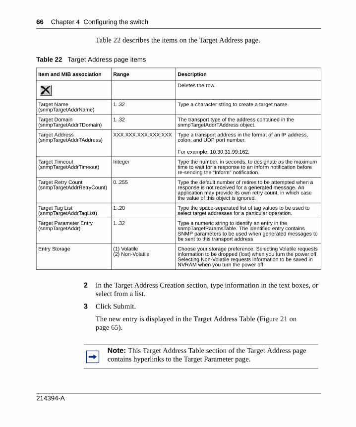
66 Chapter 4 Configuring the switch
Table 22 describes the items on the Target Address page.
2 In the Target Address Creation section, type information in the text boxes, or select from a list.
3 Click Submit.
The new entry is displayed in the Target Address Table (Figure 21 on page 65).
Table 22 Target Address page items
Item and MIB association Range Description
Deletes the row.
Target Name(snmpTargetAddrName)
1..32 Type a character string to create a target name.
Target Domain(snmpTargetAddrTDomain)
1..32 The transport type of the address contained in the snmpTargetAddrTAddress object.
Target Address(snmpTargetAddrTAddress)
XXX.XXX.XXX.XXX:XXX Type a transport address in the format of an IP address, colon, and UDP port number.
For example: 10.30.31.99:162.
Target Timeout(snmpTargetAddrTimeout)
Integer Type the number, in seconds, to designate as the maximum time to wait for a response to an inform notification before re-sending the “Inform” notification.
Target Retry Count(snmpTargetAddrRetryCount)
0..255 Type the default number of retires to be attempted when a response is not received for a generated message. An application may provide its own retry count, in which case the value of this object is ignored.
Target Tag List(snmpTargetAddrTagList)
1..20 Type the space-separated list of tag values to be used to select target addresses for a particular operation.
Target Parameter Entry(snmpTargetAddr)
1..32 Type a numeric string to identify an entry in the snmpTargetParamsTable. The identified entry contains SNMP parameters to be used when generated messages to be sent to this transport address
Entry Storage (1) Volatile(2) Non-Volatile
Choose your storage preference. Selecting Volatile requests information to be dropped (lost) when you turn the power off. Selecting Non-Volatile requests information to be saved in NVRAM when you turn the power off.
Note: This Target Address Table section of the Target Address page contains hyperlinks to the Target Parameter page.
214394-A
Chapter 4 Configuring the switch 67
Deleting an SNMPv3 target address configuration
To delete an SNMPv3 target address configuration:
1 From the main menu, choose Configuration > SNMPv3 > Target Address.
The Target Address page opens (Figure 21 on page 65).
2 In the Target Address Table, click the Delete icon for the entry you want to delete.
A message opens prompting you to confirm your request.
3 Do one of the following:
• Click Yes to delete the target address configuration.
• Click Cancel to return to the table without making changes.
Configuring an SNMPv3 management target parameter
SNMPv3 management target parameters are used during notification generation to specify the communication parameters used for exchangeswith notification recipients.
You can view a table of existing SNMPv3 target parameter configurations, create SNMPv3 target parameters that associate notifications with particular recipients, and delete existing SNMPv3 target parameter configurations.
Creating an SNMPv3 target parameter configuration
To create an SNMPv3 target parameter configuration:
1 From the main menu, choose Configuration > SNMPv3 > Target Parameter.
The Target Parameter page opens (Figure 22).
Using Web-based Management for the BayStack 380-24F Gigabit Switch

68 Chapter 4 Configuring the switch
Figure 22 Target Parameter page
Table 23 describes the items on the Target Parameter page.
2 In the Target Parameter Creation section, type information in the text boxes, or select from a list.
3 Click Submit.
The new entry appears in the Target Parameter Table (Figure 22 on page 68).
Table 23 Target Parameter page items
Item Range Description
Deletes the row.
Parameter Tag(snmpTargetParamsRowStatus)
1..32 Type a unique character string to identify the parameter tag.
Msg Processing Model(snmpTargetParamsMPModel)
(0) SNMPv1(1) SNMPv2c(2) SNMPv2*(3) SNMPv3 /USM
Choose the message processing model to be used when generating SNMP messages using this entry
Security Name(snmpTargetParamsSecuirtyName)
1..32 Type the principal on whose behalf SNMP messages are generated using this entry
Security Level(snmpTargetParamsSecuirtyLevel)
(1) noAuthNoPriv(2) authNoPriv
Choose the level of security to be used when generating SNMP messages using this entry
Entry Storage(snmpTargetParamsStorageType)
(1) Volatile(2) Non-Volatile
Choose your storage preference. Selecting Volatile requests information to be dropped (lost) when you turn the power off. Selecting Non-Volatile requests information to be saved in NVRAM when you turn the power off.
214394-A
Chapter 4 Configuring the switch 69
Deleting an SNMPv3 target parameter configuration
To delete an SNMPv3 target parameter configuration:
1 From the main menu, choose Configuration > SNMPv3 > Target Address.
The Target Address page opens (Figure 21 on page 65).
2 In the Target Parameter Table, click the Delete icon for the entry you want to delete.
A message opens prompting you to confirm your request.
3 Do one of the following:
• Click Yes to delete the target parameter configuration.
• Click Cancel to return to the table without making changes.
Configuring an SNMP trap receiver
You can configure the IP address and community string for a new SNMP trap receiver, view a table of existing SNMP trap receiver configurations, or delete an existing SNMP trap receiver configuration(s).
Creating an SNMP trap receiver configuration
To create an SNMP trap receiver configuration:
1 From the main menu, choose Configuration > SNMP Trap Receiver.
The SNMP Trap Receiver page opens (Figure 23).
Note: The SNMP Trap Receiver Table is an alternative to using the SNMPv3 Target Table and SNMPv3 Parameter Table. However, only SNMPv1 traps are configurable using this table.
Using Web-based Management for the BayStack 380-24F Gigabit Switch
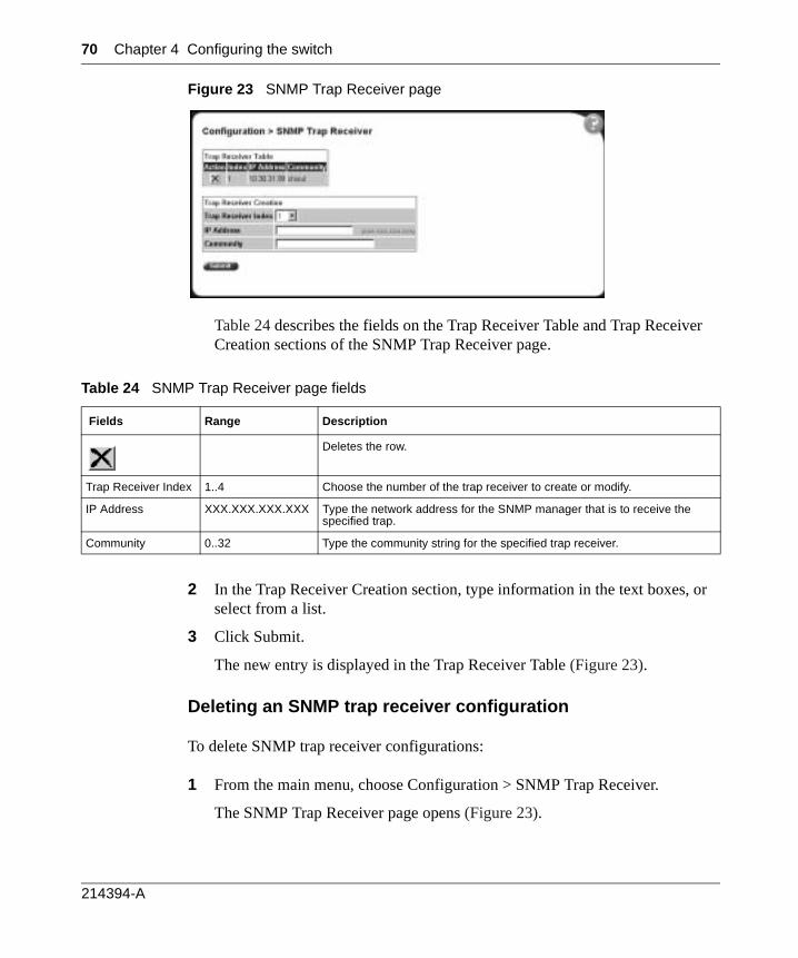
70 Chapter 4 Configuring the switch
Figure 23 SNMP Trap Receiver page
Table 24 describes the fields on the Trap Receiver Table and Trap Receiver Creation sections of the SNMP Trap Receiver page.
2 In the Trap Receiver Creation section, type information in the text boxes, or select from a list.
3 Click Submit.
The new entry is displayed in the Trap Receiver Table (Figure 23).
Deleting an SNMP trap receiver configuration
To delete SNMP trap receiver configurations:
1 From the main menu, choose Configuration > SNMP Trap Receiver.
The SNMP Trap Receiver page opens (Figure 23).
Table 24 SNMP Trap Receiver page fields
Fields Range Description
Deletes the row.
Trap Receiver Index 1..4 Choose the number of the trap receiver to create or modify.
IP Address XXX.XXX.XXX.XXX Type the network address for the SNMP manager that is to receive the specified trap.
Community 0..32 Type the community string for the specified trap receiver.
214394-A
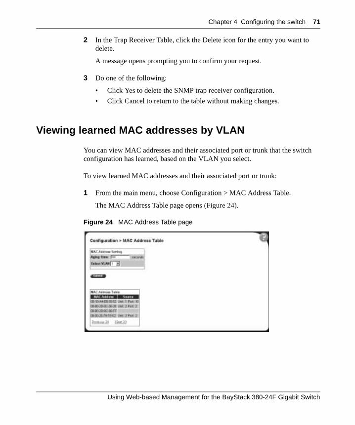
Chapter 4 Configuring the switch 71
2 In the Trap Receiver Table, click the Delete icon for the entry you want to delete.
A message opens prompting you to confirm your request.
3 Do one of the following:
• Click Yes to delete the SNMP trap receiver configuration.
• Click Cancel to return to the table without making changes.
Viewing learned MAC addresses by VLAN
You can view MAC addresses and their associated port or trunk that the switch configuration has learned, based on the VLAN you select.
To view learned MAC addresses and their associated port or trunk:
1 From the main menu, choose Configuration > MAC Address Table.
The MAC Address Table page opens (Figure 24).
Figure 24 MAC Address Table page
Using Web-based Management for the BayStack 380-24F Gigabit Switch

72 Chapter 4 Configuring the switch
Table 25 describes the fields on the MAC Address Table page.
2 In the MAC Address Setting section, choose the aging time and VLAN you want to view learned MAC addresses on.
3 Click Submit.
Your request is displayed in the MAC Address Table (Figure 24 on page 71).
Locating a specific MAC address
You can search for a specific MAC address among all the MAC addresses learned from all the VLANs. This is a useful tool for finding whether or not a switch has learned a particular address.
To locate a specific MAC addresses:
1 From the main menu, choose Configuration > Find MAC Address.
The Find MAC Address Table page opens (Figure 25).
Table 25 MAC Address Table page fields
Section Field Range Description
MAC Address Setting
Aging Time 10..1000000 Type the timeout period, in seconds, for aging out dynamically learned forwarding information. If the entry is inactive for a period of time that exceeds the specified aging time, the address is removed.
Note: Nortel Networks recommends that you use the default value of 300 seconds.
Select VLAN 1..64 Choose the VLAN on which to view learned MAC addresses.
MAC Address Table
MAC Address The unicast MAC address for which the bridge has forwarding and/or filtering information.
Source The source of the discovered MAC address.
214394-A
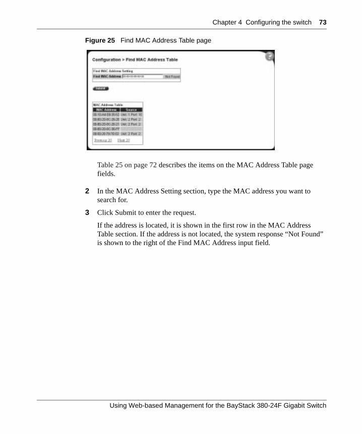
Chapter 4 Configuring the switch 73
Figure 25 Find MAC Address Table page
Table 25 on page 72 describes the items on the MAC Address Table page fields.
2 In the MAC Address Setting section, type the MAC address you want to search for.
3 Click Submit to enter the request.
If the address is located, it is shown in the first row in the MAC Address Table section. If the address is not located, the system response “Not Found” is shown to the right of the Find MAC Address input field.
Using Web-based Management for the BayStack 380-24F Gigabit Switch
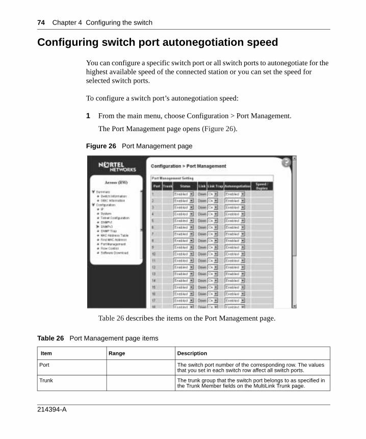
74 Chapter 4 Configuring the switch
Configuring switch port autonegotiation speed
You can configure a specific switch port or all switch ports to autonegotiate for the highest available speed of the connected station or you can set the speed for selected switch ports.
To configure a switch port’s autonegotiation speed:
1 From the main menu, choose Configuration > Port Management.
The Port Management page opens (Figure 26).
Figure 26 Port Management page
Table 26 describes the items on the Port Management page.
Table 26 Port Management page items
Item Range Description
Port The switch port number of the corresponding row. The values that you set in each switch row affect all switch ports.
Trunk The trunk group that the switch port belongs to as specified in the Trunk Member fields on the MultiLink Trunk page.
214394-A
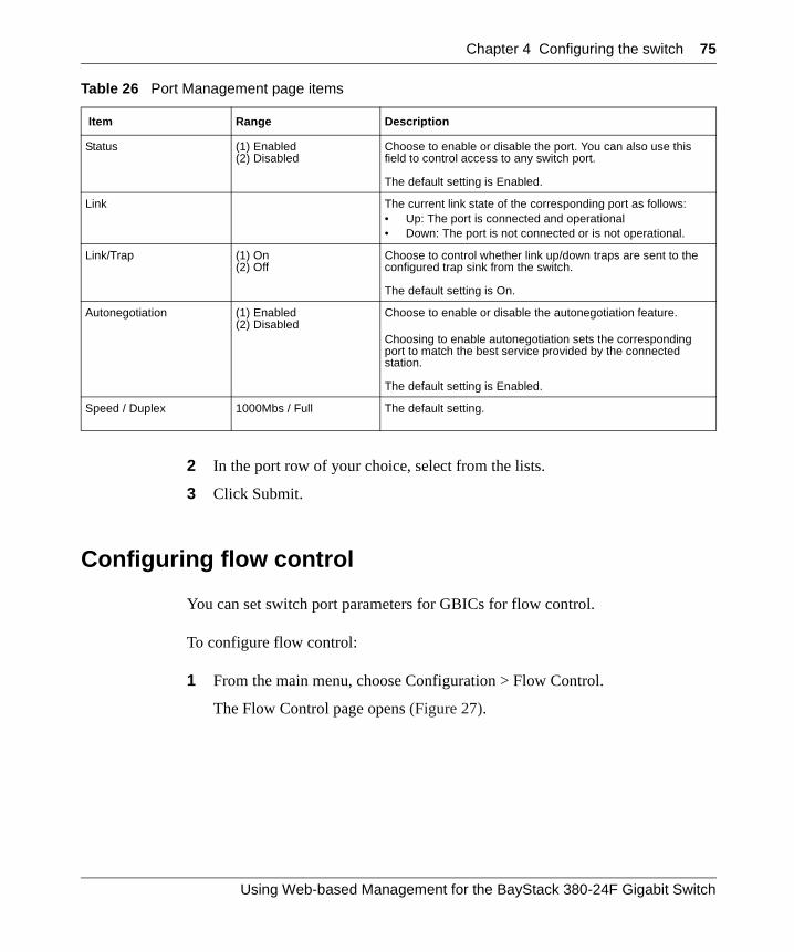
Chapter 4 Configuring the switch 75
2 In the port row of your choice, select from the lists.
3 Click Submit.
Configuring flow control
You can set switch port parameters for GBICs for flow control.
To configure flow control:
1 From the main menu, choose Configuration > Flow Control.
The Flow Control page opens (Figure 27).
Status (1) Enabled(2) Disabled
Choose to enable or disable the port. You can also use this field to control access to any switch port.
The default setting is Enabled.
Link The current link state of the corresponding port as follows: • Up: The port is connected and operational• Down: The port is not connected or is not operational.
Link/Trap (1) On(2) Off
Choose to control whether link up/down traps are sent to the configured trap sink from the switch.
The default setting is On.
Autonegotiation (1) Enabled(2) Disabled
Choose to enable or disable the autonegotiation feature.
Choosing to enable autonegotiation sets the corresponding port to match the best service provided by the connected station.
The default setting is Enabled.
Speed / Duplex 1000Mbs / Full The default setting.
Table 26 Port Management page items
Item Range Description
Using Web-based Management for the BayStack 380-24F Gigabit Switch
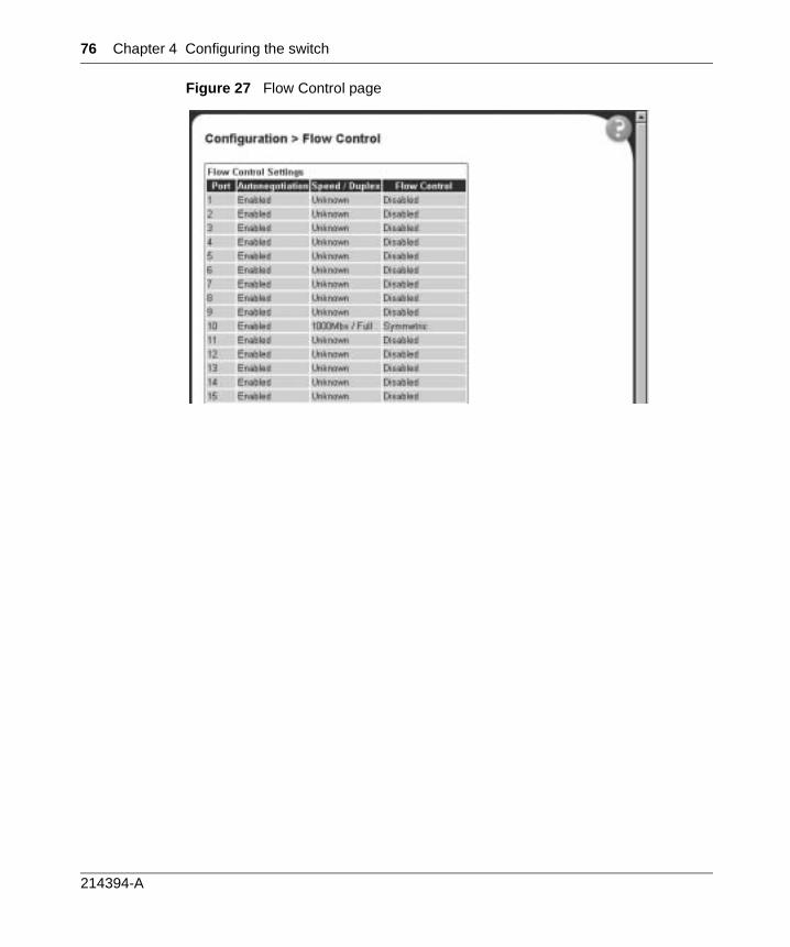
76 Chapter 4 Configuring the switch
Figure 27 Flow Control page
214394-A
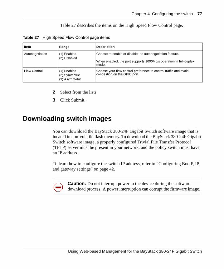
Chapter 4 Configuring the switch 77
Table 27 describes the items on the High Speed Flow Control page.
2 Select from the lists.
3 Click Submit.
Downloading switch images
You can download the BayStack 380-24F Gigabit Switch software image that is located in non-volatile flash memory. To download the BayStack 380-24F Gigabit Switch software image, a properly configured Trivial File Transfer Protocol (TFTP) server must be present in your network, and the policy switch must have an IP address.
To learn how to configure the switch IP address, refer to “Configuring BootP, IP, and gateway settings” on page 42.
Table 27 High Speed Flow Control page items
Item Range Description
Autonegotiation (1) Enabled(2) Disabled
Choose to enable or disable the autonegotiation feature.
When enabled, the port supports 1000Mb/s operation in full-duplex mode.
Flow Control (1) Enabled(2) Symmetric(3) Asymmetric
Choose your flow control preference to control traffic and avoid congestion on the GBIC port.
Caution: Do not interrupt power to the device during the software download process. A power interruption can corrupt the firmware image.
Using Web-based Management for the BayStack 380-24F Gigabit Switch
78 Chapter 4 Configuring the switch
To download a switch image:
1 From the main menu, choose Configuration > Software Download.
The Software Download page opens (Figure 28).
Figure 28 Software Download page
Table 28 describes the fields on the Software Download page.
Table 28 Software Download page fields
Fields Range Description
Current Running Version The version of the current running software.
Local Store Version The local version of the software in the flash memory.
BS380-24F Image Filename 1..30 Type the software image load filename.
BS380-24F Diagnostics Filename
1..30 Type the diagnostics filename.
Image Filename 1..30 Type the image filename.
TFTP Server IP Address XXX.XXX.XXX.XXX Type the IP address of your TFTP load host.
Download Option (1) No(2) BS380-24F Image(3) BS380-24FDiagnostics
Choose the software image to load.
214394-A
Chapter 4 Configuring the switch 79
2 Type information in the text boxes, or select from a list.
3 Click Submit.
The software download process automatically completes without user intervention. The process erases the contents of flash memory and replaces it with a new software image. Take care not to interrupt the download process until after it runs to completion (the process can take up to 10 minutes, depending on network conditions).
When the download process is complete, the switch automatically resets and the new software image initiates a self-test.
During the download process, the BayStack 380-24F Gigabit Switch is not operational. You can monitor the progress of the download process by observing the LED indications.
Table 29 describes the LED indications during the software download process.
Note: The LED indications described in Table 29 apply to a 24-port switch model.
Table 29 LED Indications during the software download process
Phase Description LED Indications
1 The switch downloads the new software image.
1000 Mb/s port status LEDs: The LEDs begin to turn on in succession beginning with port 1 on one side and port 24 on the other side.
2 The switch erases the flash memory. 1000 Mb/s port status LEDs: The LEDs begin to turn on in succession beginning with port 1 on one side and port 24 on the other side.
3 The switch programs the new software image into the flash memory.
1000 Mb/s port status LEDs: The LEDs begin to turn on in succession beginning with port 1 on one side and port 24 on the other side.
4 The switch resets automatically. After the reset completes, the new software image initiates the switch self-test, which comprises various diagnostic routines and subtests. All of the LEDs will display solid green.
The LEDs display various patterns to indicate that the subtests are in progress.
Using Web-based Management for the BayStack 380-24F Gigabit Switch
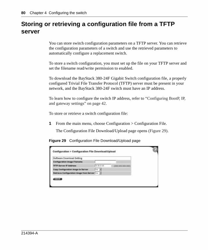
80 Chapter 4 Configuring the switch
Storing or retrieving a configuration file from a TFTP server
You can store switch configuration parameters on a TFTP server. You can retrieve the configuration parameters of a switch and use the retrieved parameters to automatically configure a replacement switch.
To store a switch configuration, you must set up the file on your TFTP server and set the filename read/write permission to enabled.
To download the BayStack 380-24F Gigabit Switch configuration file, a properly configured Trivial File Transfer Protocol (TFTP) server must be present in your network, and the BayStack 380-24F switch must have an IP address.
To learn how to configure the switch IP address, refer to “Configuring BootP, IP, and gateway settings” on page 42.
To store or retrieve a switch configuration file:
1 From the main menu, choose Configuration > Configuration File.
The Configuration File Download/Upload page opens (Figure 29).
Figure 29 Configuration File Download/Upload page
214394-A
Chapter 4 Configuring the switch 81
Table 30 describes the items on the Configuration File Download/Upload page.
2 Type information in the text boxes, or select from a list.
3 Click Submit.
Requirements for storing or retrieving parameters on a TFTP server
The following requirements apply when storing and retrieving configuration parameters on a TFTP server:
• The Configuration File feature can only be used to copy switch configuration parameters to other switches.
• A configuration file obtained from a switch can only be used to configure other switches that have the same firmware revision and model type as the donor switch.
• The configuration file also duplicates any settings that exist for any GBIC that is installed in the donor switch.
• If you use the configuration file to configure another switch that has the same GBIC model installed, the configuration file settings will also apply to and override the existing GBIC settings.
Table 30 Configuration File Download/Upload page items
Item Range Description
Configuration Image Filename
1..32 Type the configuration file name.
TFTP Server IP Address XXX.XXX.XXX.XXX Type the IP address of the TFTP load host.
Copy Configuration Image to Server
(1) Yes(2) No
Choose whether or not to copy the configuration image to the server.
Retrieve Configuration Image from Server
(1) Yes(2) No
Choose whether or not to retrieve the configuration image from a server. If you choose Yes, the download process begins immediately and, when completed, causes the switch to reset with the new configuration parameters.
Using Web-based Management for the BayStack 380-24F Gigabit Switch
82 Chapter 4 Configuring the switch
Table 31 describes the parameters that are not saved to the configuration file.
Table 31 Parameters not saved to the configuration file
These parameters are not saved: Used in this screen:
IP Configuration/Setup
In-Band Switch IP Address
In-Band Subnet Mask
Default Gateway
Configuration Image Filename Configuration File Download/Upload
TFTP Server IP Address
Console Read-Only Switch Password Console/Comm Port Configuration
Console Read-Write Switch Password
214394-A
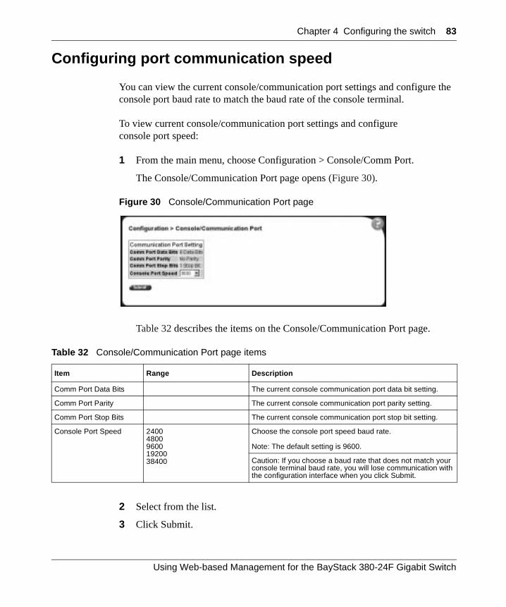
Chapter 4 Configuring the switch 83
Configuring port communication speed
You can view the current console/communication port settings and configure the console port baud rate to match the baud rate of the console terminal.
To view current console/communication port settings and configure console port speed:
1 From the main menu, choose Configuration > Console/Comm Port.
The Console/Communication Port page opens (Figure 30).
Figure 30 Console/Communication Port page
Table 32 describes the items on the Console/Communication Port page.
2 Select from the list.
3 Click Submit.
Table 32 Console/Communication Port page items
Item Range Description
Comm Port Data Bits The current console communication port data bit setting.
Comm Port Parity The current console communication port parity setting.
Comm Port Stop Bits The current console communication port stop bit setting.
Console Port Speed 2400480096001920038400
Choose the console port speed baud rate.
Note: The default setting is 9600.
Caution: If you choose a baud rate that does not match your console terminal baud rate, you will lose communication with the configuration interface when you click Submit.
Using Web-based Management for the BayStack 380-24F Gigabit Switch

84 Chapter 4 Configuring the switch
214394-A
85
Chapter 5Configuring remote network monitoring (RMON)
The RMON management information base (MIB) is an interface between the RMON agent on a BayStack 380-24FSwitch and RMON management applications such as the Web-based management user interface. It defines objects that are suitable for the management of any type of network. Some groups are specifically targeted for Ethernet networks.
The RMON agent continuously collects statistics and proactively monitors the switch.
This RMON options available to you are:
• “Configuring RMON fault threshold parameters”, (next)
• “Viewing the RMON fault event log” on page 88
• “Viewing the system log” on page 90
• “Viewing RMON Ethernet statistics” on page 92
• “Viewing RMON history” on page 96
Configuring RMON fault threshold parameters
Alarms are useful when you need to know when the value of some variable goes out of range. RMON alarms can be defined on any MIB variable that resolves to an integer value. String variables (such as system description) cannot be used as alarm variables.
Using Web-based Management for the BayStack 380-24F Gigabit Switch
86 Chapter 5 Configuring remote network monitoring (RMON)
Creating an RMON fault threshold
You can create the RMON threshold parameters for fault notification (alarms).
To create an RMON threshold:
1 From the main menu, choose Fault > RMON Threshold.
The RMON Threshold page opens (Figure 31).
Figure 31 RMON Threshold page
Table 33 describes the items on the RMON Threshold page.
Table 33 RMON Threshold page items
Item Range Description
Deletes the row.
Index/Alarm Index
1..10 Type the unique number to identify the alarm entry.
Target Integer The switch number and port number.
Port 1..24 Choose the port on which to set an alarm.
214394-A
Chapter 5 Configuring remote network monitoring (RMON) 87
Parameter (1) Good-Bytes(2) Good-Packets(3) Multicast(4) Broadcast(5) CRC-Errors(6) Runts(7) Fragments(8) Frame-Too-Long(9) Collisions
Choose the sampled statistic.
Current Level Integer The value of the statistic during the last sampling period.
Note: If the sample type is Delta, the value is the difference between the samples at the beginning and end of the period. If the sample type is Absolute, the value is the sampled value at the end of the period.
Rising Level Integer Type the event entry to be used when a rising threshold is crossed.
Note: When the current sampled value is greater than or equal to this threshold, and the value at the last sampling interval was less than this threshold, a single event will be generated. After a rising event is generated, another such event is not generated until the sampled value falls below this threshold and reaches the Falling Threshold.
Rising Action (1) None(2) Log(3) SNMP Trap(4) Log and Trap
Choose the type of notification for the event. Selecting Log generates an entry in the RMON Event Log table for each event. Selecting SNMP Trap sends an SNMP trap to one or more management stations.
Interval Type the time period (in seconds) to sample data and compare the data to the rising and falling thresholds.
Sample/Alarm Sample
(1) Absolute(2) Delta
Choose the sampling method.
Absolute: Absolute alarms are defined on the current value of the alarm variable. An example of an alarm defined with absolute value is card operating status. Because this value is not cumulative, but instead represents states, such as card up (value 1) and card down (value 2), you set it for absolute value. Therefore, an alarm could be created with a rising value of 2 and a falling value of 1 to alert a user to whether the card is up or down. Delta: Most alarm variables related to Ethernet traffic are set to delta value. Delta alarms are defined based on the difference in the value of the alarm variable between the start of the polling period and the end of the polling period. Delta alarms are sampled twice per polling period. For each sample, the last two values are added together and compared to the threshold values. This process increases precision and allows for the detection of threshold crossings that span the sampling boundary. Therefore, if you keep track of the current values of a given delta-valued alarm and add them together, the result is twice the actual value. (This result is not an error in the software.)
Table 33 RMON Threshold page items (continued)
Item Range Description
Using Web-based Management for the BayStack 380-24F Gigabit Switch
88 Chapter 5 Configuring remote network monitoring (RMON)
2 In the RMON Threshold Creation section, type information in the text boxes, or select from a list.
3 Click Submit.
The new configuration is displayed in the RMON Threshold Table (Figure 31 on page 86).
Deleting an RMON threshold configuration
To delete an existing RMON threshold configuration:
1 From the main menu, choose Fault > RMON Threshold.
The RMON Threshold page opens (Figure 31 on page 86.)
2 In the RMON Threshold Table, click the Delete icon for the entry you want to delete.
A message opens prompting you to confirm your request.
3 Do one of the following:
• Click Yes to delete the RMON threshold configuration.
• Click Cancel to return to the RMON Threshold page without making changes.
Viewing the RMON fault event log
RMON events and alarms work together to notify you when values in your network go out of a specified range. When values pass the specified ranges, the alarm is triggered and “fires.” The event specifies how the activity is recorded.
Note: RMON threshold configurations are not modifiable. They must be deleted and the information recreated.
214394-A
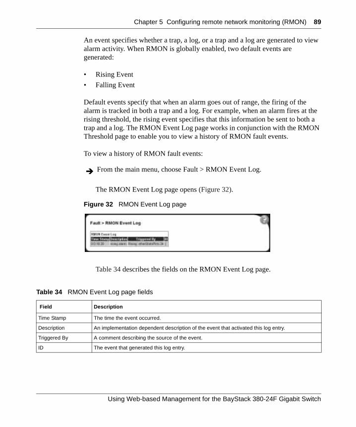
Chapter 5 Configuring remote network monitoring (RMON) 89
An event specifies whether a trap, a log, or a trap and a log are generated to view alarm activity. When RMON is globally enabled, two default events are generated:
• Rising Event
• Falling Event
Default events specify that when an alarm goes out of range, the firing of the alarm is tracked in both a trap and a log. For example, when an alarm fires at the rising threshold, the rising event specifies that this information be sent to both a trap and a log. The RMON Event Log page works in conjunction with the RMON Threshold page to enable you to view a history of RMON fault events.
To view a history of RMON fault events:
The RMON Event Log page opens (Figure 32).
Figure 32 RMON Event Log page
Table 34 describes the fields on the RMON Event Log page.
From the main menu, choose Fault > RMON Event Log.
Table 34 RMON Event Log page fields
Field Description
Time Stamp The time the event occurred.
Description An implementation dependent description of the event that activated this log entry.
Triggered By A comment describing the source of the event.
ID The event that generated this log entry.
Using Web-based Management for the BayStack 380-24F Gigabit Switch
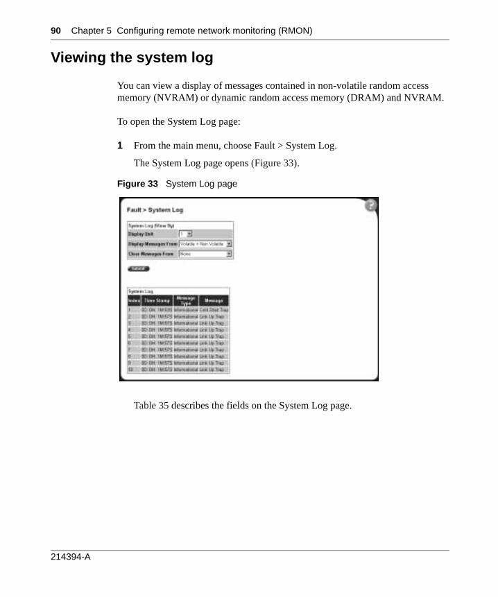
90 Chapter 5 Configuring remote network monitoring (RMON)
Viewing the system log
You can view a display of messages contained in non-volatile random access memory (NVRAM) or dynamic random access memory (DRAM) and NVRAM.
To open the System Log page:
1 From the main menu, choose Fault > System Log.
The System Log page opens (Figure 33).
Figure 33 System Log page
Table 35 describes the fields on the System Log page.
214394-A
Chapter 5 Configuring remote network monitoring (RMON) 91
2 In the System Log (View By) section do one or more of the following:
• Choose the number of the switch from which to display messages.
• Choose where to display messages from.
• Choose to clear messages from Volatile or Non Volatile memory.
3 Click Submit.
The results of your request are displayed in the System Log section (Figure 33 on page 90).
Table 35 System Log page fields
Section Field Range Description
System Log Display Messages From
(1) Non Volatile(2) Volatile + Non Volatile
Choose to display messages from Non Volatile memory (NVRAM) or Volatile (DRAM) and Non Volatile memory.
The default settings is Non Volatile.
Clear Messages From
(1) Volatile(2) Volatile + Non Volatile(3) None
Choose to clear messages from Volatile memory or Volatile and Non Volatile memory.
The default settings is None (do not clear messages)
System Log Index The number of the event.
Time Stamp The time, in hundreths of a second, between system initialization and the time the log messages entered the system.
Message Type The type of message. The options are (1) Critical, (2) Serious, and (3) Informational.
Message A character string that identifies the origin of the message and the reason why the message was generated.
Using Web-based Management for the BayStack 380-24F Gigabit Switch
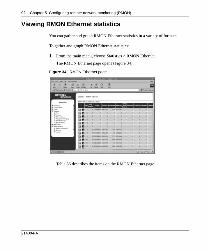
92 Chapter 5 Configuring remote network monitoring (RMON)
Viewing RMON Ethernet statistics
You can gather and graph RMON Ethernet statistics in a variety of formats.
To gather and graph RMON Ethernet statistics:
1 From the main menu, choose Statistics > RMON Ethernet.
The RMON Ethernet page opens (Figure 34).
Figure 34 RMON Ethernet page
Table 36 describes the items on the RMON Ethernet page.
214394-A
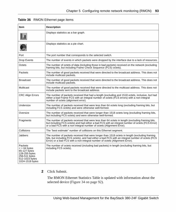
Chapter 5 Configuring remote network monitoring (RMON) 93
2 Click Submit.
The RMON Ethernet Statistics Table is updated with information about the selected device (Figure 34 on page 92).
Table 36 RMON Ethernet page items
Item Description
Displays statistics as a bar graph.
Displays statistics as a pie chart.
Port The port number that corresponds to the selected switch.
Drop Events The number of events in which packets were dropped by the interface due to a lack of resources.
Octets The number of octets of data (including those in bad packets) received on the network (excluding framing bits, but including Frame Check Sequence (FCS) octets).
Packets The number of good packets received that were directed to the broadcast address. This does not include multicast packets.
Broadcast The number of good packets received that were directed to the broadcast address. This does not include multicast packets.
Multicast The number of good packets received that were directed to the multicast address. This does not include packets sent to the broadcast address.
CRC Align Errors The number of packets received that had a length (excluding and 1518 octets, inclusive, but had either a bad Frame FCS with an integral number of octets (FCS errors) with a non-integral number of octets (alignment error).
Undersize The number of packets received that were less than 64 octets long (excluding framing bits, but including FCS octets) and were otherwise well-formed.
Oversize The number of packets received that were longer than 1518 octets long (excluding framing bits, but including FCS octets) and were otherwise well-formed.
Fragments The number of packets received that were less than 64 octets in length (excluding framing bits, but including FCS octets) and had either a bad FCS with an integral number of octets (FCS Error) or a bad FCS with a non-integral number of octets (Alignment Error).
Collisions The “best estimate” number of collisions on this Ethernet segment.
Jabbers The number of packets received that were longer than 1518 octets in length (excluding framing bits, but including FCS octets), and had either a bad FCS with an integral number of octets (FCS Error) or a bad FCS with a non-integral number of octets (Alignment Error).
Packets< = 64 bytes65-127 bytes128-255 bytes256-511 bytes512-1023 bytes1024-1518 bytes
The number of octets received (including bad packets) in length (excluding framing bits, but including FCS octets).
Using Web-based Management for the BayStack 380-24F Gigabit Switch
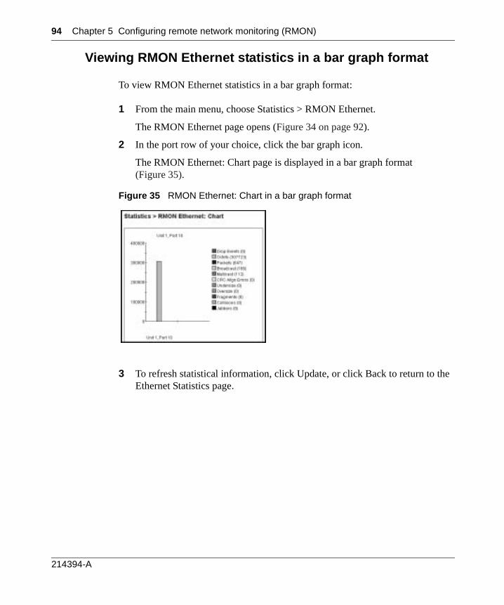
94 Chapter 5 Configuring remote network monitoring (RMON)
Viewing RMON Ethernet statistics in a bar graph format
To view RMON Ethernet statistics in a bar graph format:
1 From the main menu, choose Statistics > RMON Ethernet.
The RMON Ethernet page opens (Figure 34 on page 92).
2 In the port row of your choice, click the bar graph icon.
The RMON Ethernet: Chart page is displayed in a bar graph format (Figure 35).
Figure 35 RMON Ethernet: Chart in a bar graph format
3 To refresh statistical information, click Update, or click Back to return to the Ethernet Statistics page.
214394-A
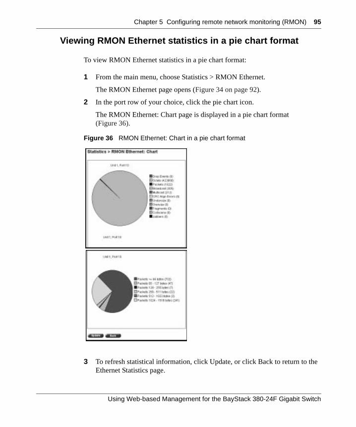
Chapter 5 Configuring remote network monitoring (RMON) 95
Viewing RMON Ethernet statistics in a pie chart format
To view RMON Ethernet statistics in a pie chart format:
1 From the main menu, choose Statistics > RMON Ethernet.
The RMON Ethernet page opens (Figure 34 on page 92).
2 In the port row of your choice, click the pie chart icon.
The RMON Ethernet: Chart page is displayed in a pie chart format (Figure 36).
Figure 36 RMON Ethernet: Chart in a pie chart format
3 To refresh statistical information, click Update, or click Back to return to the Ethernet Statistics page.
Using Web-based Management for the BayStack 380-24F Gigabit Switch
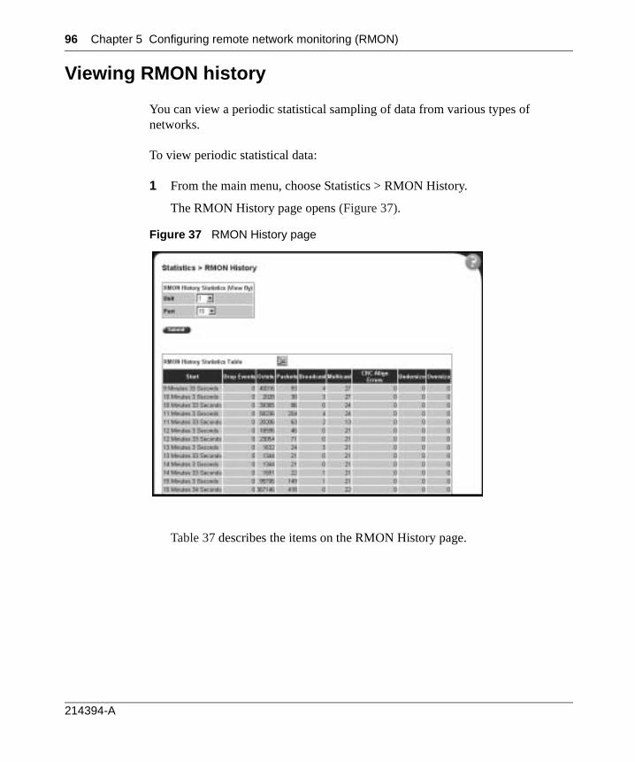
96 Chapter 5 Configuring remote network monitoring (RMON)
Viewing RMON history
You can view a periodic statistical sampling of data from various types of networks.
To view periodic statistical data:
1 From the main menu, choose Statistics > RMON History.
The RMON History page opens (Figure 37).
Figure 37 RMON History page
Table 37 describes the items on the RMON History page.
214394-A
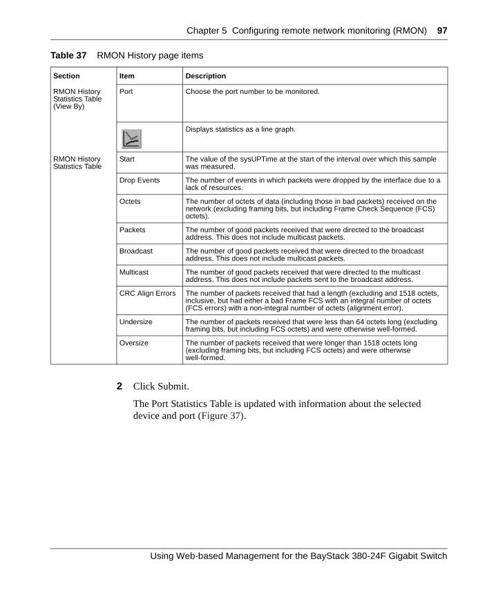
Chapter 5 Configuring remote network monitoring (RMON) 97
2 Click Submit.
The Port Statistics Table is updated with information about the selected device and port (Figure 37).
Table 37 RMON History page items
Section Item Description
RMON History Statistics Table(View By)
Port Choose the port number to be monitored.
Displays statistics as a line graph.
RMON History Statistics Table
Start The value of the sysUPTime at the start of the interval over which this sample was measured.
Drop Events The number of events in which packets were dropped by the interface due to a lack of resources.
Octets The number of octets of data (including those in bad packets) received on the network (excluding framing bits, but including Frame Check Sequence (FCS) octets).
Packets The number of good packets received that were directed to the broadcast address. This does not include multicast packets.
Broadcast The number of good packets received that were directed to the broadcast address. This does not include multicast packets.
Multicast The number of good packets received that were directed to the multicast address. This does not include packets sent to the broadcast address.
CRC Align Errors The number of packets received that had a length (excluding and 1518 octets, inclusive, but had either a bad Frame FCS with an integral number of octets (FCS errors) with a non-integral number of octets (alignment error).
Undersize The number of packets received that were less than 64 octets long (excluding framing bits, but including FCS octets) and were otherwise well-formed.
Oversize The number of packets received that were longer than 1518 octets long (excluding framing bits, but including FCS octets) and were otherwise well-formed.
Using Web-based Management for the BayStack 380-24F Gigabit Switch

98 Chapter 5 Configuring remote network monitoring (RMON)
Viewing RMON statistics in a line graph format
You can view RMON statistical data in a line graph format.
To view statistics in a line graph format:
1 From the main menu, choose Statistics > RMON History.
The RMON History page opens (Figure 37 on page 97).
2 In the RMON History Statistics Table, click the line graph icon.
The RMON History: Chart page opens in a line graph format (Figure 38).
Figure 38 RMON History page: Chart in line graph format
3 Click Back to return to the RMON History page.
214394-A
99
Chapter 6Viewing system statistics
The options available to monitor system statistical data are:
• “Viewing port statistics”, (next)
• “Viewing interface statistics” on page 105
• “Viewing Ethernet error statistics” on page 109
• “Viewing transparent bridging statistics” on page 112
Viewing port statistics
You can view detailed statistics about a selected switch port configuration. Both received and transmitted statistics are displayed so that you can compare throughput or other port parameters.
To view statistical data about a selected switch port:
1 From the main menu, choose Statistics > Port.
The Port page opens (Figure 39).
Using Web-based Management for the BayStack 380-24F Gigabit Switch
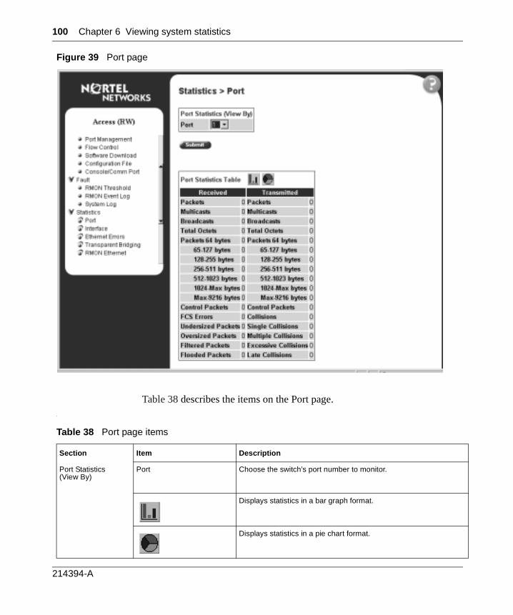
100 Chapter 6 Viewing system statistics
Figure 39 Port page
Table 38 describes the items on the Port page..
Table 38 Port page items
Section Item Description
Port Statistics(View By)
Port Choose the switch’s port number to monitor.
Displays statistics in a bar graph format.
Displays statistics in a pie chart format.
214394-A
Chapter 6 Viewing system statistics 101
Port Statistics Table Packets The number of packets received/transmitted on this port, including bad packets, broadcast packets, and multicast packets.
Multicast The number of good multicast packets received/transmitted on this port, excluding broadcast packets.
Broadcasts The number of good broadcast packets received/transmitted onthis port.
Total Octets The number of octets of data received/transmitted on this port, including data in bad packets and FCS octets, and framing bits.
Packets = 64 bytes The number of packets this size received/transmitted successfully on this port.
Packets 65-127 bytes The number of packets this size received/transmitted successfully on this port.
Packets 128-255 bytes The number of packets this size received/transmitted successfully on this port.
Packets 256-511 bytes The number of packets this size received/transmitted successfully on this port.
Packets 512-1023 bytes The number of packets this size received/transmitted successfully on this port.
Packets 1024 or more bytes The number of packets this size received/transmitted successfully on this port.
Max 9216 Bytes The maximum number of packets received/transmitted successfully on this port.
Control Packets The number of controlled packets received on the port.
FCS Errors The number of valid-size packets received on this port with proper framing but discarded because of cyclic redundancy check (CRC) errors.
Undersized Packets The number of packets received on this port with fewer than 64 bytes and with proper CRC and framing (also known as short frames or runts).
Oversized Packets The number of packets that were received on this port with proper CRC and framing that meet the following requirements:
• 1518 bytes if no VLAN tag exists• 1522 bytes if a VLAN tag exists
Filtered Packets The number of packets filtered, but not forwarded on this port.
Flooded Packets The number of packets flooded (forwarded) through this port because the destination address was not recognized in the address database.
Frame Errors The number of valid-size packets received on this port but discarded because of CRC errors and improper framing.
Table 38 Port page items (continued)
Section Item Description
Using Web-based Management for the BayStack 380-24F Gigabit Switch
102 Chapter 6 Viewing system statistics
2 Click Submit.
The Port Statistics Table is updated with information about the selected device and port (Figure 42 on page 105).
3 To update the statistical information, click Update.
Zeroing ports
To clear the statistical information for the currently displayed port:
To clear the statistical information for all ports in a switch configuration:
Port Statistics Table, cont.
Collisions The number of collisions detected on this port.
Single Collisions The number of packets that were transmitted successfully on this port after a single collision.
Multiple Collisions The number of packets that were transmitted successfully on this port after more than one collision.
Excessive Collisions The number of packets lost on this port due to excessive collisions.
Late Collisions The number of packets collisions that occurred after a total length of time that exceeded 512 bit-times of packet transmission.
Click Zero Port.
Click Zero All Ports.
Table 38 Port page items (continued)
Section Item Description
214394-A
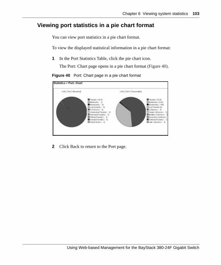
Chapter 6 Viewing system statistics 103
Viewing port statistics in a pie chart format
You can view port statistics in a pie chart format.
To view the displayed statistical information in a pie chart format:
1 In the Port Statistics Table, click the pie chart icon.
The Port: Chart page opens in a pie chart format (Figure 40).
Figure 40 Port: Chart page in a pie chart format
2 Click Back to return to the Port page.
Using Web-based Management for the BayStack 380-24F Gigabit Switch
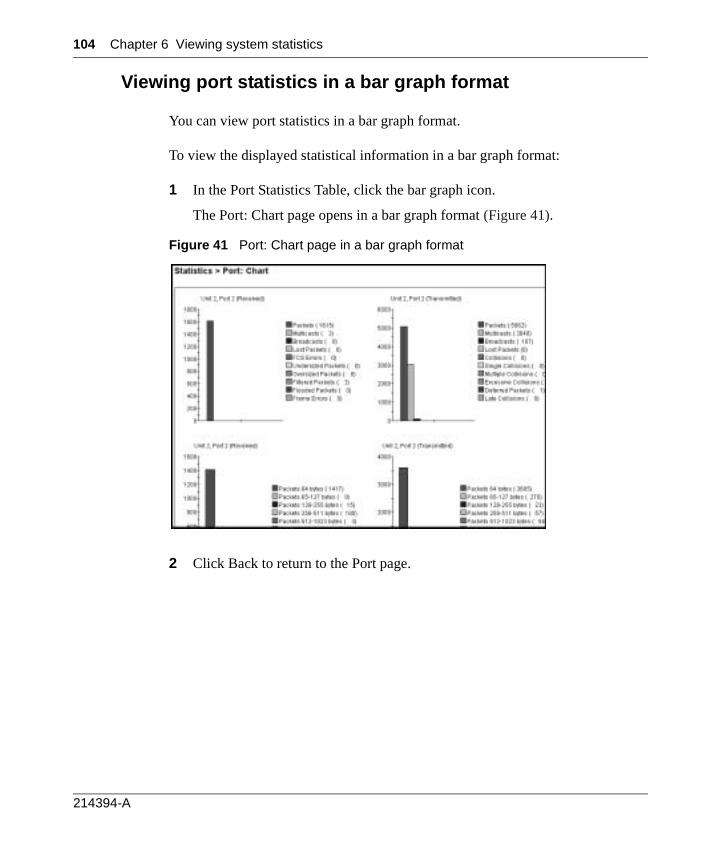
104 Chapter 6 Viewing system statistics
Viewing port statistics in a bar graph format
You can view port statistics in a bar graph format.
To view the displayed statistical information in a bar graph format:
1 In the Port Statistics Table, click the bar graph icon.
The Port: Chart page opens in a bar graph format (Figure 41).
Figure 41 Port: Chart page in a bar graph format
2 Click Back to return to the Port page.
214394-A
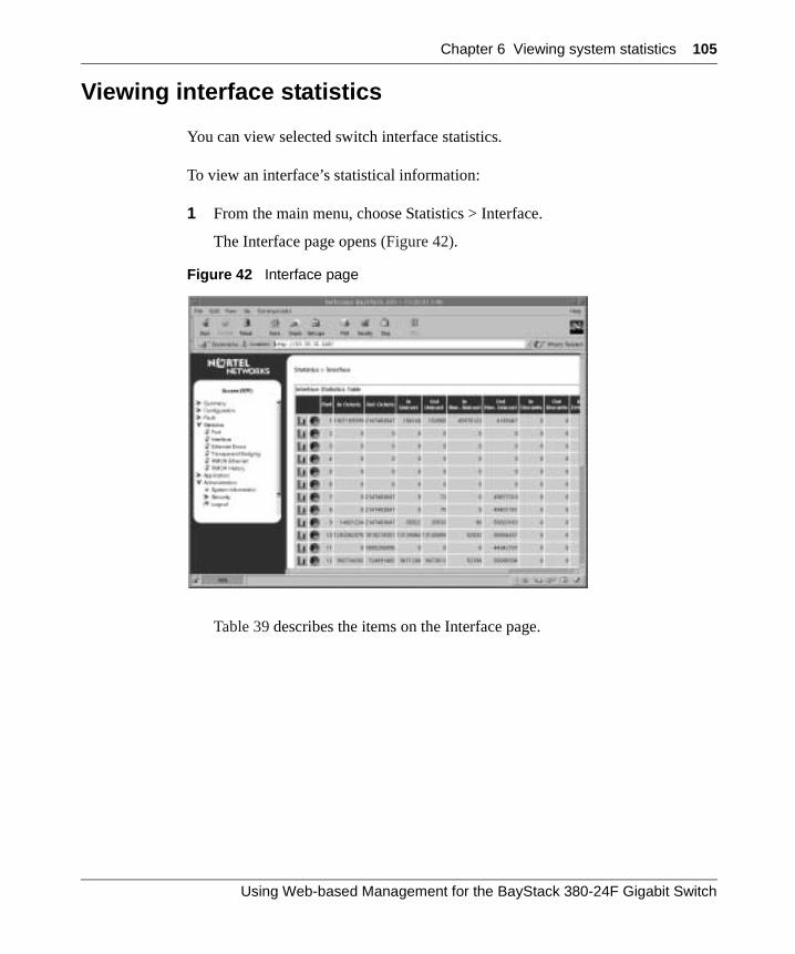
Chapter 6 Viewing system statistics 105
Viewing interface statistics
You can view selected switch interface statistics.
To view an interface’s statistical information:
1 From the main menu, choose Statistics > Interface.
The Interface page opens (Figure 42).
Figure 42 Interface page
Table 39 describes the items on the Interface page.
Using Web-based Management for the BayStack 380-24F Gigabit Switch
106 Chapter 6 Viewing system statistics
2 To update the statistical information, click Update.
Table 39 Interface page items
Item Description
Displays statistics in a bar graph format.
Displays statistics in a pie chart format.
Port The port number corresponding to the selected switch.
In Octets The number of octets received on the interface, including framing characters.
Out Octets The number of octets transmitted out of the interface, including framing characters.
In Unicast The number of subnetwork-unicast packets delivered to a higher-layer protocol.
Out Unicast The number of packets that higher-layer protocols requested be transmitted to a subnetwork-unicast address, including those that were discarded or not sent.
In Non-Unicast The number of non-unicast packets, for example, subnetwork-broadcast or subnetwork-multicast packets, delivered to a higher protocol.
Out Non-Unicast The number of packets that higher-level protocols requested be transmitted to a non-unicast address. For example, a subnetwork-broadcast or a subnetwork multicast address, including those that were discarded or not sent.
In Discards The number of inbound packets which were selected to be discarded even though no errors were detected to prevent their being delivered to a higher-layer protocol. Packet discarding is not arbitrary. One reason for discarding packets is to free buffer space.
Out Discards The number of outbound packets which were selected to be discarded even though no errors were detected to prevent their being transmitted. Packet discarding is not arbitrary. One reason for discarding packets is to free buffer space.
In Errors The number of inbound packets that contained errors preventing them from being deliverable to a higher-layer protocol.
Out Errors The number of outbound packets that could not be transmitted because of errors.
In Unknown Protocols
The number of packets received through the interface which were discards due to an unknown or unsupported protocol.
214394-A
Chapter 6 Viewing system statistics 107
Viewing interface statistics in a pie chart format
You can view interface statistics in a pie chart format.
To view interface statistics in a pie chart format:
1 From the main menu, choose Statistics > Interface.
The Interface page opens (Figure 42 on page 105).
2 In the port row of your choice, click the pie chart icon.
The Interface: Chart page opens in a pie chart format (Figure 43).
Figure 43 Interface: Chart in a pie chart format
3 To update the statistical information, click Update, or click Back to return to the Interface page.
Using Web-based Management for the BayStack 380-24F Gigabit Switch
108 Chapter 6 Viewing system statistics
Viewing interface statistics in a bar graph format
You can view interface statistics in a bar graph format.
To view interface statistics in a bar graph format:
1 From the main menu, choose Statistics > Interface.
The Interface page opens (Figure 42 on page 105).
2 In the port row of your choice, click the bar graph icon.
The Interface: Chart page opens in a bar graph format (Figure 43).
Figure 44 Interface: Chart in a bar graph format
3 To update the statistical information, click Update, or click Back to return to the Interface page.
214394-A
Chapter 6 Viewing system statistics 109
Viewing Ethernet error statistics
You can view Ethernet error statistics for each monitored interface linked to the Baystack 380 Switch.
To view Ethernet error statistics:
1 From the main menu, choose Statistics > Ethernet Errors.
The Ethernet Errors page opens (Figure 45).
Figure 45 Ethernet Errors page
Table 40 describes the items on the Ethernet Errors page.
Using Web-based Management for the BayStack 380-24F Gigabit Switch
110 Chapter 6 Viewing system statistics
2 To refresh the statistical information, click Update.
Table 40 Ethernet Errors page items
Item Description
Displays statistics in a bar graph format.
Displays statistics in a pie chart format.
Port The port number corresponding to the selected switch.
Alignment Errors The number of frames received on a particular interface that are not an integral number of octets in length and do not pass the FCS check.
FCS Errors The number of frames received on a particular interface that are an integral number of octets in length, but do not pass the FCS check.
Internal MAC Transmit Errors
The number of frames for which transmission on a particular interface fails due to an internal MAC sublayer transmit error. A frame only is counted by an instance of this object if it is not counted by the corresponding instance of either the dot3StatsLateCollisions object, the dot3StatsExcessiveCollisions object, or the dot3StatsCarrierSenseErrors object.
Internal MAC Receive Errors
The number of frames for which reception on a particular interface fails due to an internal MAC sublayer transmit error. A frame only is counted by an instance of this object if it is not counted by the corresponding instance of either the dot3StatsLateCollisions object, the dot3StatsExcessiveCollisions object, or the dot3StatsCarrierSenseErrors object.
Carrier Sense Errors The number of times that the carrier sense conditions was lost or never asserted when attempting to transmit a frame on a particular interface.
Frame Too Long The number of frames received on a particular interface that exceed the maximum permitted frame size.
SQE Test Errors The number of times that the SQE TEST ERROR message is generated by the PLS sublayer for a particular interface. The SQE TEST ERROR is defined in section 7.2.2.2.4 of ANSI/IEEE 802.3-1985, and its generation is described in section 7.2.4.6 of the same document.
Deferred Transmissions The number of frames for which the first transmission attempt on a particular interface is delayed because the medium is busy.
Single Collision Frames The number of successfully transmitted frames on a particular interface for which transmission is inhibited by more than one collision.
Multiple Collision Frames The number of successfully transmitted frames on a particular interface for which transmission is inhibited by a single collision.
Late Collisions The number of times a collision is detected on a particular interface later than 512 bit-times into the transmission of a packet.
Excessive Collisions The number of frames for which transmission on a particular interface fails due to excessive collisions.
214394-A
Chapter 6 Viewing system statistics 111
Viewing Ethernet error statistics in a pie chart format
You can view Ethernet Errors statistics in a pie chart format.
To view Ethernet Errors statistics in a pie chart format:
1 From the main menu, choose Statistics > Ethernet Errors.
The Ethernet Errors page opens (Figure 45 on page 109).
2 In the port row of your choice, click the pie chart icon.
The Ethernet Errors: Chart page opens in a pie chart format (Figure 46).
Figure 46 Ethernet Error: Chart in a pie chart format
3 To update the statistical information, click Update, or click Back to return to the Ethernet Errors page.
Viewing Ethernet error statistics in a bar graph format
You can view Ethernet Errors statistics in a bar graph format.
To view Ethernet errors statistics in a bar graph format:
1 From the main menu, choose Statistics > Ethernet Errors.
The Ethernet Errors page opens (Figure 45 on page 109).
Using Web-based Management for the BayStack 380-24F Gigabit Switch

112 Chapter 6 Viewing system statistics
2 In the port row of your choice, click the bar graph icon.
The Ethernet Errors: Chart page opens in a bar graph format (Figure 47).
Figure 47 Ethernet Error: Chart in a bar graph format
3 To update the statistical information, click Update, or click Back to return to the Ethernet Errors page.
Viewing transparent bridging statistics
You can view the transparent bridging statistics measured for each monitored interface on the device.
To view transparent bridging statistics:
1 From the main menu, choose Statistics > Transparent Bridging.
The Transparent Bridging page opens (Figure 48).
214394-A
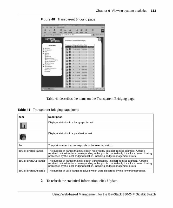
Chapter 6 Viewing system statistics 113
Figure 48 Transparent Bridging page
Table 41 describes the items on the Transparent Bridging page.
2 To refresh the statistical information, click Update.
Table 41 Transparent Bridging page items
Item Description
Displays statistics in a bar graph format.
Displays statistics in a pie chart format.
Port The port number that corresponds to the selected switch.
dot1dTpPortInFrames The number of frames that have been received by this port from its segment. A frame received on the interface corresponding to this port is counted only if it is for a protocol being processed by the local bridging function, including bridge management errors.
dot1dTpPortOutFrames The number of frames that have been transmitted by this port from its segment. A frame received on the interface corresponding to this port is counted only if it is for a protocol being processed by the local bridging function, including bridge management errors.
dot1dTpPortInDiscards The number of valid frames received which were discarded by the forwarding process.
Using Web-based Management for the BayStack 380-24F Gigabit Switch
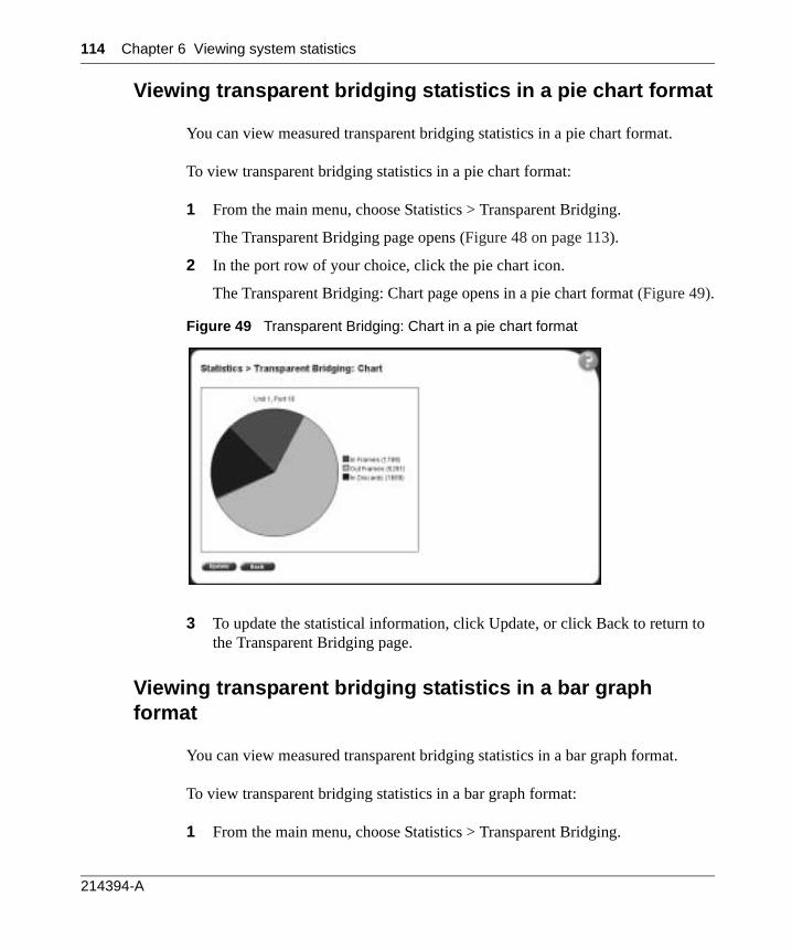
114 Chapter 6 Viewing system statistics
Viewing transparent bridging statistics in a pie chart format
You can view measured transparent bridging statistics in a pie chart format.
To view transparent bridging statistics in a pie chart format:
1 From the main menu, choose Statistics > Transparent Bridging.
The Transparent Bridging page opens (Figure 48 on page 113).
2 In the port row of your choice, click the pie chart icon.
The Transparent Bridging: Chart page opens in a pie chart format (Figure 49).
Figure 49 Transparent Bridging: Chart in a pie chart format
3 To update the statistical information, click Update, or click Back to return to the Transparent Bridging page.
Viewing transparent bridging statistics in a bar graph format
You can view measured transparent bridging statistics in a bar graph format.
To view transparent bridging statistics in a bar graph format:
1 From the main menu, choose Statistics > Transparent Bridging.
214394-A
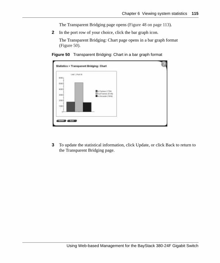
Chapter 6 Viewing system statistics 115
The Transparent Bridging page opens (Figure 48 on page 113).
2 In the port row of your choice, click the bar graph icon.
The Transparent Bridging: Chart page opens in a bar graph format (Figure 50).
Figure 50 Transparent Bridging: Chart in a bar graph format
3 To update the statistical information, click Update, or click Back to return to the Transparent Bridging page.
Using Web-based Management for the BayStack 380-24F Gigabit Switch

116 Chapter 6 Viewing system statistics
214394-A
117
Chapter 7Configuring application settings
The options available to configure application settings are:
• “Configuring port mirroring”, (next)
• “Mac address security” on page 119
• “Creating and managing virtual LANs (VLANs)” on page 128
• “Configuring VLANs” on page 132
• “Configuring broadcast domains” on page 137
• “Viewing VLAN port information” on page 138
• “Managing Spanning Tree Protocol (STP)” on page 140
• “Changing Spanning Tree bridge switch settings” on page 142
• “Configuring MultiLink Trunk (MLT) members” on page 144
• “Monitoring MLT traffic” on page 147
Configuring port mirroring
The BayStack 380-24F Switch supports port mirroring to analyze traffic. You can view existing port mirroring activity and you can configure a specific switch port to mirror up to two specified ports. When you configure port mirroring, you specify port-based monitoring.
Using Web-based Management for the BayStack 380-24F Gigabit Switch
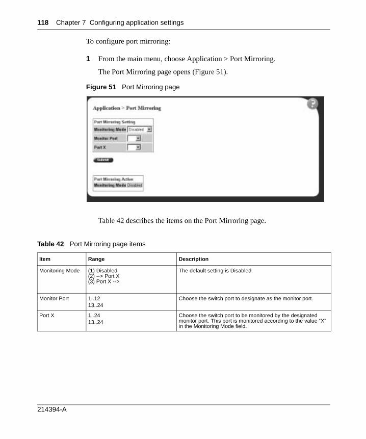
118 Chapter 7 Configuring application settings
To configure port mirroring:
1 From the main menu, choose Application > Port Mirroring.
The Port Mirroring page opens (Figure 51).
Figure 51 Port Mirroring page
Table 42 describes the items on the Port Mirroring page.
Table 42 Port Mirroring page items
Item Range Description
Monitoring Mode (1) Disabled(2) --> Port X(3) Port X -->
The default setting is Disabled.
Monitor Port 1..1213..24
Choose the switch port to designate as the monitor port.
Port X 1..2413..24
Choose the switch port to be monitored by the designated monitor port. This port is monitored according to the value “X” in the Monitoring Mode field.
214394-A
Chapter 7 Configuring application settings 119
2 Type information in the text boxes, or select from a list.
3 Click Submit.
Mac address security
The MAC address-based security feature of the Web-based management system allows you to specify a range of system responses to unauthorized network access to your switch. The response can range from sending a trap to disabling the port.
The network access control is based on the MAC source addresses (SAs) of the authorized stations. You can specify a list of up to 448 MAC source addresses that are authorized to access the switch. You can also specify the ports that each MAC source address is allowed to access. The options for port access include: NONE, ALL, and single or multiple ports that are specified in a list, for example, 1-4. You must also include the MAC source address of any router or switch connected to any secure ports.
You can configure the BayStack 380-24F Gigabit Switch to drop all packets having a specified MAC destination address (DA). You can also create a list of up to 10 MAC DAs you want to filter.The packet with the specified MAC DA will be dropped regardless of the ingress port, source address (SA) intrusion, or VLAN membership.
Configuring MAC address-based security
To configure MAC address-based security using the Web-based management system:
1 From the main menu, choose Application > MAC Address Security > Security Configuration.
The Security Configuration page opens (Figure 52).
Note: Ensure that you do not enter the MAC address of the switch or stack you are working on.
Using Web-based Management for the BayStack 380-24F Gigabit Switch
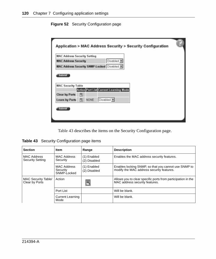
120 Chapter 7 Configuring application settings
Figure 52 Security Configuration page
Table 43 describes the items on the Security Configuration page.
Table 43 Security Configuration page items
Section Item Range Description
MAC Address Security Setting
MAC Address Security
(1) Enabled(2) Disabled
Enables the MAC address security features.
MAC Address Security SNMP-Locked
(1) Enabled(2) Disabled
Enables locking SNMP, so that you cannot use SNMP to modify the MAC address security features.
MAC Security Table/Clear by Ports
Action Allows you to clear specific ports from participation in the MAC address security features.
Port List Will be blank.
Current Learning Mode
Will be blank.
214394-A
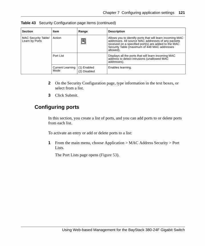
Chapter 7 Configuring application settings 121
2 On the Security Configuration page, type information in the text boxes, or select from a list.
3 Click Submit.
Configuring ports
In this section, you create a list of ports, and you can add ports to or delete ports from each list.
To activate an entry or add or delete ports to a list:
1 From the main menu, choose Application > MAC Address Security > Port Lists.
The Port Lists page opens (Figure 53).
MAC Security Table/Learn by Ports
Action Allows you to identify ports that will learn incoming MAC addresses. All source MAC addresses of any packets received on a specified port(s) are added to the MAC Security Table (maximum of 448 MAC addresses allowed).
Port List Displays all the ports that will learn incoming MAC address to detect intrusions (unallowed MAC addresses).
Current Learning Mode
(1) Enabled(2) Disabled
Enables learning.
Table 43 Security Configuration page items (continued)
Section Item Range Description
Using Web-based Management for the BayStack 380-24F Gigabit Switch
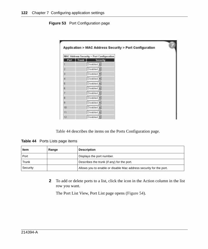
122 Chapter 7 Configuring application settings
Figure 53 Port Configuration page
Table 44 describes the items on the Ports Configuration page.
2 To add or delete ports to a list, click the icon in the Action column in the list row you want.
The Port List View, Port List page opens (Figure 54).
Table 44 Ports Lists page items
Item Range Description
Port Displays the port number.
Trunk Describes the trunk (if any) for the port.
Security Allows you to enable or disable Mac address security for the port.
214394-A
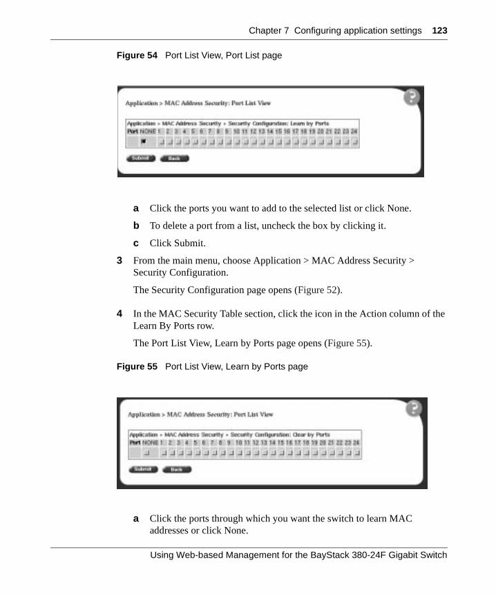
Chapter 7 Configuring application settings 123
Figure 54 Port List View, Port List page
a Click the ports you want to add to the selected list or click None.
b To delete a port from a list, uncheck the box by clicking it.
c Click Submit.
3 From the main menu, choose Application > MAC Address Security > Security Configuration.
The Security Configuration page opens (Figure 52).
4 In the MAC Security Table section, click the icon in the Action column of the Learn By Ports row.
The Port List View, Learn by Ports page opens (Figure 55).
Figure 55 Port List View, Learn by Ports page
a Click the ports through which you want the switch to learn MAC addresses or click None.
Using Web-based Management for the BayStack 380-24F Gigabit Switch
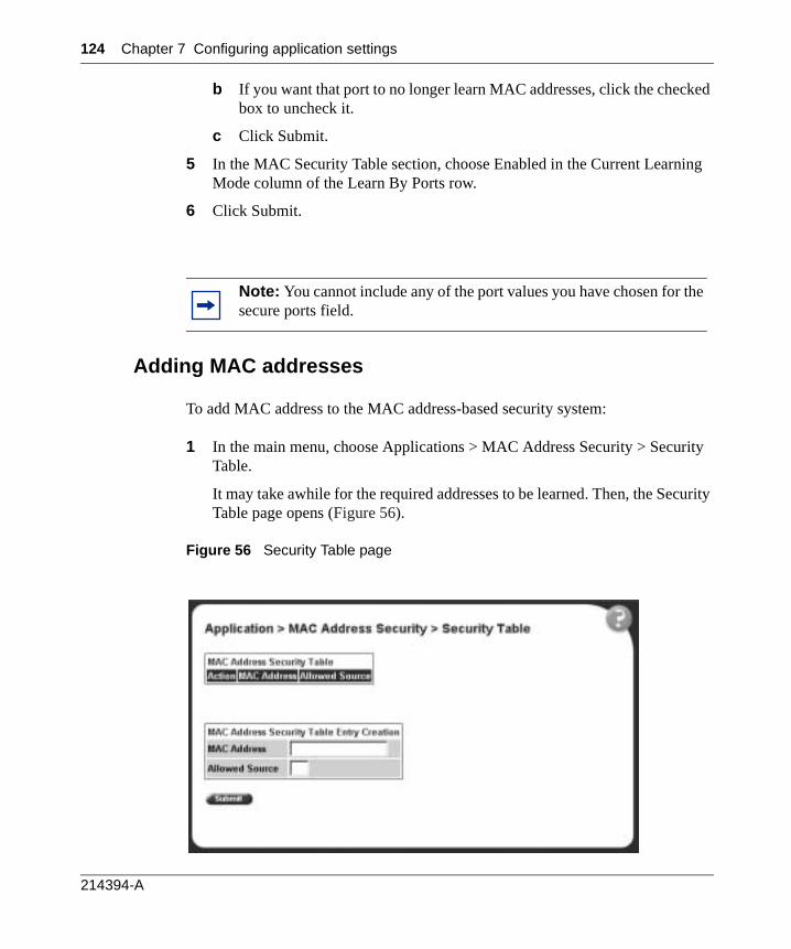
124 Chapter 7 Configuring application settings
b If you want that port to no longer learn MAC addresses, click the checked box to uncheck it.
c Click Submit.
5 In the MAC Security Table section, choose Enabled in the Current Learning Mode column of the Learn By Ports row.
6 Click Submit.
Adding MAC addresses
To add MAC address to the MAC address-based security system:
1 In the main menu, choose Applications > MAC Address Security > Security Table.
It may take awhile for the required addresses to be learned. Then, the Security Table page opens (Figure 56).
Figure 56 Security Table page
Note: You cannot include any of the port values you have chosen for the secure ports field.
214394-A
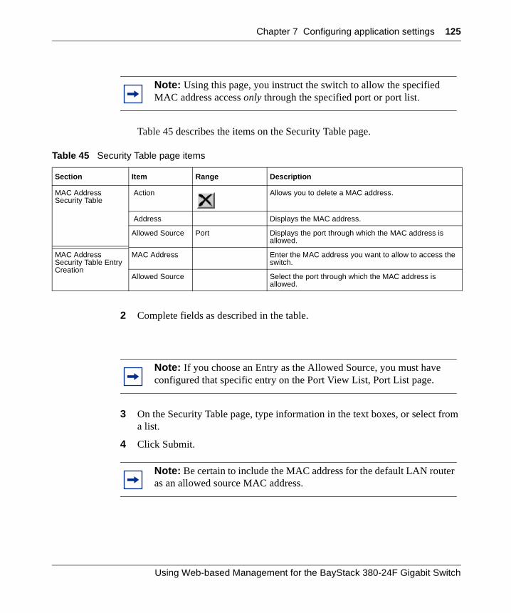
Chapter 7 Configuring application settings 125
Table 45 describes the items on the Security Table page.
2 Complete fields as described in the table.
3 On the Security Table page, type information in the text boxes, or select from a list.
4 Click Submit.
Note: Using this page, you instruct the switch to allow the specified MAC address access only through the specified port or port list.
Table 45 Security Table page items
Section Item Range Description
MAC Address Security Table
Action Allows you to delete a MAC address.
Address Displays the MAC address.
Allowed Source Port Displays the port through which the MAC address is allowed.
MAC Address Security Table Entry Creation
MAC Address Enter the MAC address you want to allow to access the switch.
Allowed Source Select the port through which the MAC address is allowed.
Note: If you choose an Entry as the Allowed Source, you must have configured that specific entry on the Port View List, Port List page.
Note: Be certain to include the MAC address for the default LAN router as an allowed source MAC address.
Using Web-based Management for the BayStack 380-24F Gigabit Switch
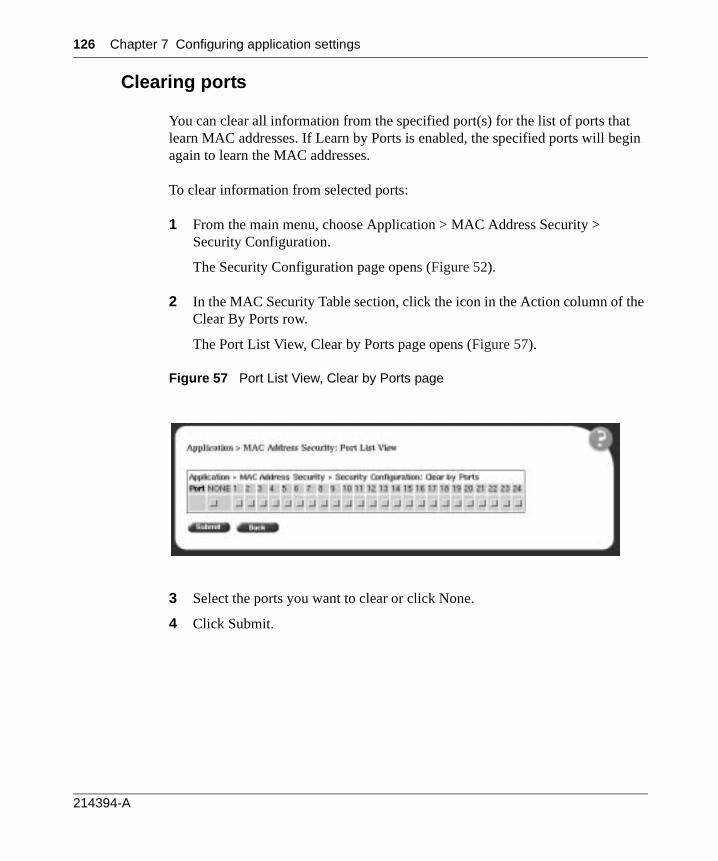
126 Chapter 7 Configuring application settings
Clearing ports
You can clear all information from the specified port(s) for the list of ports that learn MAC addresses. If Learn by Ports is enabled, the specified ports will begin again to learn the MAC addresses.
To clear information from selected ports:
1 From the main menu, choose Application > MAC Address Security > Security Configuration.
The Security Configuration page opens (Figure 52).
2 In the MAC Security Table section, click the icon in the Action column of the Clear By Ports row.
The Port List View, Clear by Ports page opens (Figure 57).
Figure 57 Port List View, Clear by Ports page
3 Select the ports you want to clear or click None.
4 Click Submit.
214394-A
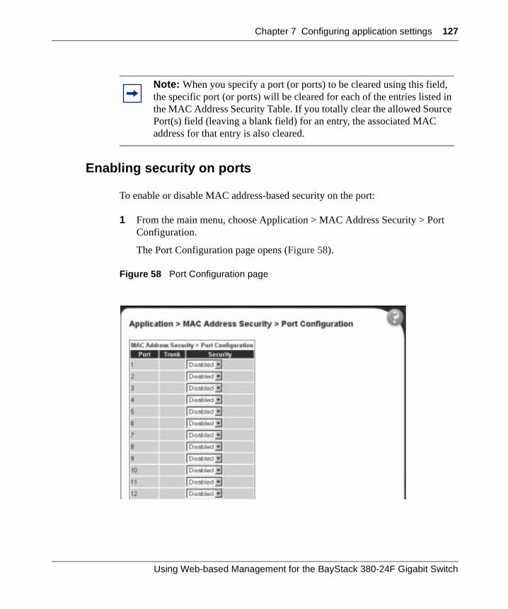
Chapter 7 Configuring application settings 127
Enabling security on ports
To enable or disable MAC address-based security on the port:
1 From the main menu, choose Application > MAC Address Security > Port Configuration.
The Port Configuration page opens (Figure 58).
Figure 58 Port Configuration page
Note: When you specify a port (or ports) to be cleared using this field, the specific port (or ports) will be cleared for each of the entries listed in the MAC Address Security Table. If you totally clear the allowed Source Port(s) field (leaving a blank field) for an entry, the associated MAC address for that entry is also cleared.
Using Web-based Management for the BayStack 380-24F Gigabit Switch
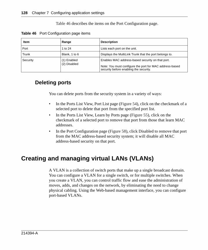
128 Chapter 7 Configuring application settings
Table 46 describes the items on the Port Configuration page.
Deleting ports
You can delete ports from the security system in a variety of ways:
• In the Ports List View, Port List page (Figure 54), click on the checkmark of a selected port to delete that port from the specified port list.
• In the Ports List View, Learn by Ports page (Figure 55), click on the checkmark of a selected port to remove that port from those that learn MAC addresses.
• In the Port Configuration page (Figure 58), click Disabled to remove that port from the MAC address-based security system; it will disable all MAC address-based security on that port.
Creating and managing virtual LANs (VLANs)
A VLAN is a collection of switch ports that make up a single broadcast domain. You can configure a VLAN for a single switch, or for multiple switches. When you create a VLAN, you can control traffic flow and ease the administration of moves, adds, and changes on the network, by eliminating the need to change physical cabling. Using the Web-based management interface, you can configure port-based VLANs.
Table 46 Port Configuration page items
Item Range Description
Port 1 to 24 Lists each port on the unit.
Trunk Blank, 1 to 6 Displays the MultiLink Trunk that the port belongs to.
Security (1) Enabled(2) Disabled
Enables MAC address-based security on that port.
Note: You must configure the port for MAC address-based security before enabling the security.
214394-A
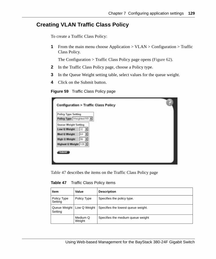
Chapter 7 Configuring application settings 129
Creating VLAN Traffic Class Policy
To create a Traffic Class Policy:
1 From the main menu choose Application > VLAN > Configuration > Traffic Class Policy.
The Configuration > Traffic Class Policy page opens (Figure 62).
2 In the Traffic Class Policy page, choose a Policy type.
3 In the Queue Weight setting table, select values for the queue weight.
4 Click on the Submit button.
Figure 59 Traffic Class Policy page
Table 47 describes the items on the Traffic Class Policy page
Table 47 Traffic Class Policy items
Item Value Description
Policy Type Setting
Policy Type Specifies the policy type.
Queue WeightSetting
Low Q Weight Specifies the lowest queue weight.
Medium Q Weight
Specifies the medium queue weight
Using Web-based Management for the BayStack 380-24F Gigabit Switch
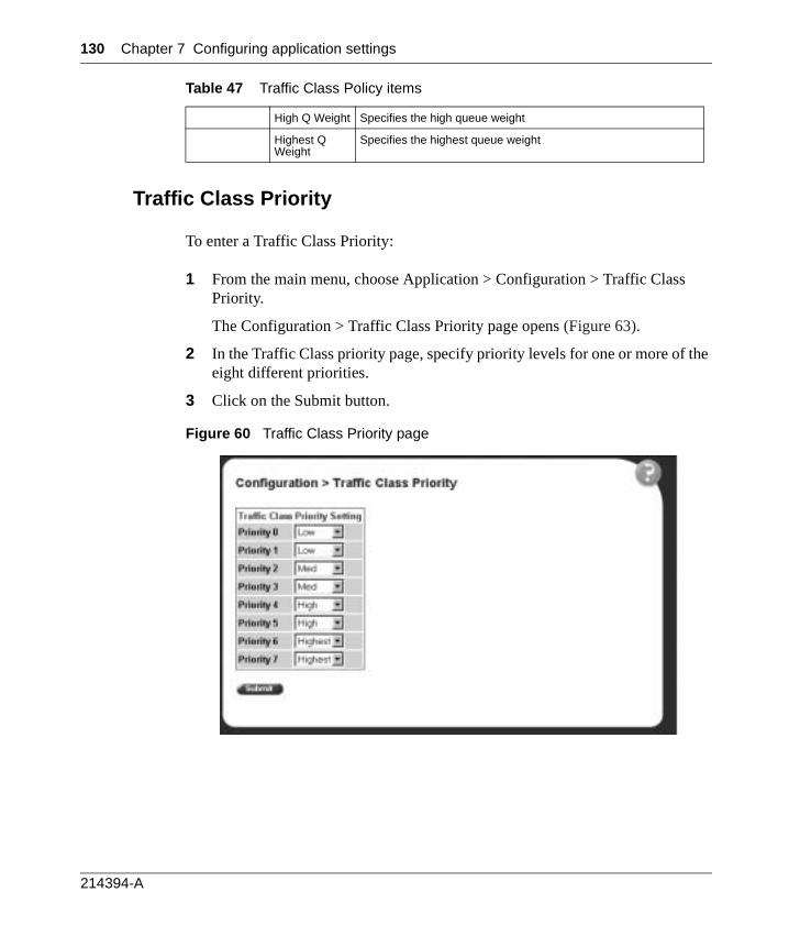
130 Chapter 7 Configuring application settings
Traffic Class Priority
To enter a Traffic Class Priority:
1 From the main menu, choose Application > Configuration > Traffic Class Priority.
The Configuration > Traffic Class Priority page opens (Figure 63).
2 In the Traffic Class priority page, specify priority levels for one or more of the eight different priorities.
3 Click on the Submit button.
Figure 60 Traffic Class Priority page
High Q Weight Specifies the high queue weight
Highest Q Weight
Specifies the highest queue weight
Table 47 Traffic Class Policy items
214394-A
Chapter 7 Configuring application settings 131
Table 51 describes the items on the Traffic Class Priority page.
Port-based VLANs
A port-based VLAN is a VLAN in which the ports are explicitly configured to be in the VLAN. When you create a port-based VLAN on a switch, you assign a VLAN identification number (VLAN ID) and specify which ports belong to the VLAN. The VLAN ID is used to coordinate VLANs across multiple switches.
Table 48 Traffic Class Priority items
Type of Setting Priority Description
Traffic Class Priority Setting Priority 0 Specifies priority 0
Priority 1 Specifies priority 1
Priority 2 Specifies priority 2
Priority 3 Specifies priority 3
Priority 4 Specifies priority 4
Priority 5 Specifies priority 5
Priority 6 Specifies priority 6
Priority 7 Specifies priority 7
Using Web-based Management for the BayStack 380-24F Gigabit Switch

132 Chapter 7 Configuring application settings
Configuring VLANs
You can create VLANs by assigning switch ports as VLAN members and you can designate an existing VLAN to act as the management VLAN.
To open the VLAN Configuration page:
The VLAN Configuration page opens (Figure 61).
Figure 61 VLAN Configuration page
Table 49 describes the items on the VLAN Configuration page.
From the main menu, choose Application > VLAN > VLAN Configuration.
214394-A
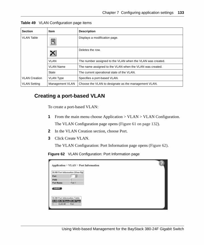
Chapter 7 Configuring application settings 133
Creating a port-based VLAN
To create a port-based VLAN:
1 From the main menu choose Application > VLAN > VLAN Configuration.
The VLAN Configuration page opens (Figure 61 on page 132).
2 In the VLAN Creation section, choose Port.
3 Click Create VLAN.
The VLAN Configuration: Port Information page opens (Figure 62).
Figure 62 VLAN Configuration: Port Information page
Table 49 VLAN Configuration page items
Section Item Description
VLAN Table Displays a modification page.
Deletes the row.
VLAN The number assigned to the VLAN when the VLAN was created.
VLAN Name The name assigned to the VLAN when the VLAN was created.
State The current operational state of the VLAN.
VLAN Creation VLAN Type Specifies a port-based VLAN.
VLAN Setting Management VLAN Choose the VLAN to designate as the management VLAN.
Using Web-based Management for the BayStack 380-24F Gigabit Switch
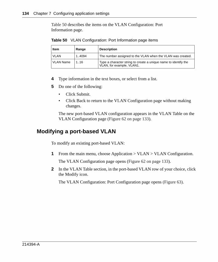
134 Chapter 7 Configuring application settings
Table 50 describes the items on the VLAN Configuration: Port Information page.
4 Type information in the text boxes, or select from a list.
5 Do one of the following:
• Click Submit.
• Click Back to return to the VLAN Configuration page without making changes.
The new port-based VLAN configuration appears in the VLAN Table on the VLAN Configuration page (Figure 62 on page 133).
Modifying a port-based VLAN
To modify an existing port-based VLAN:
1 From the main menu, choose Application > VLAN > VLAN Configuration.
The VLAN Configuration page opens (Figure 62 on page 133).
2 In the VLAN Table section, in the port-based VLAN row of your choice, click the Modify icon.
The VLAN Configuration: Port Configuration page opens (Figure 63).
Table 50 VLAN Configuration: Port Information page items
Item Range Description
VLAN 1..4094 The number assigned to the VLAN when the VLAN was created.
VLAN Name 1..16 Type a character string to create a unique name to identify the VLAN, for example, VLAN1.
214394-A
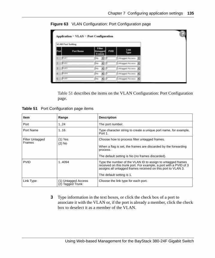
Chapter 7 Configuring application settings 135
Figure 63 VLAN Configuration: Port Configuration page
Table 51 describes the items on the VLAN Configuration: Port Configuration page.
3 Type information in the text boxes, or click the check box of a port to associate it with the VLAN or, if the port is already a member, click the check box to deselect it as a member of the VLAN.
Table 51 Port Configuration page items
Item Range Description
Port 1..24 The port number.
Port Name 1..16 Type character string to create a unique port name, for example, Port 1.
Filter Untagged Frames
(1) Yes(2) No
Choose how to process filter untagged frames.
When a flag is set, the frames are discarded by the forwarding process.
The default setting is No (no frames discarded).
PVID 1..4094 Type the number of the VLAN ID to assign to untagged frames received on this trunk port. For example, a port with a PVID of 3 assigns all untagged frames received on this port to VLAN 3.
The default setting is 1.
Link Type (1) Untagged Access(2) Tagged Trunk
Choose the link type for each port.
Using Web-based Management for the BayStack 380-24F Gigabit Switch
136 Chapter 7 Configuring application settings
4 Do one of the following:
• Click Submit.
• Click Back to return to the VLAN Configuration page without making changes.
The modified VLAN configuration is displayed in the VLAN Table (Figure 61 on page 132).
Selecting a management VLAN
You can select any VLAN to perform as the management VLAN. VLAN 1 is the default management VLAN for the switch. To set this field, the VLAN State field value must be active.
To select a VLAN as the management VLAN:
1 From the main menu, choose Application > VLAN > VLAN Configuration.
The VLAN Configuration page opens (Figure 62 on page 133).
2 In the VLAN Setting section, choose the VLAN to assign as your management VLAN.
3 Click Submit.
Deleting a VLAN configuration
To delete a VLAN configuration:
1 From the main menu, choose Application > VLAN > VLAN Configuration.
The VLAN Configuration page opens (Figure 62 on page 133).
2 In the VLAN Table, click the Delete icon for the entry you want to delete.
A message opens prompting you to confirm your request.
3 Do one of the following:
• Click Yes to delete the VLAN configuration.
• Click Cancel to return to the VLAN Configuration page without making changes.
214394-A
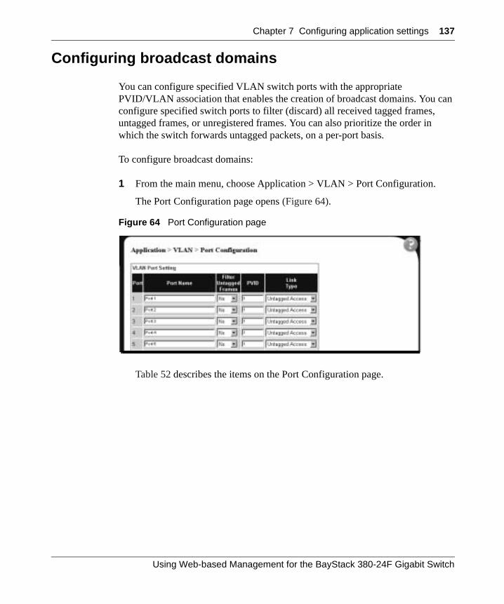
Chapter 7 Configuring application settings 137
Configuring broadcast domains
You can configure specified VLAN switch ports with the appropriate PVID/VLAN association that enables the creation of broadcast domains. You can configure specified switch ports to filter (discard) all received tagged frames, untagged frames, or unregistered frames. You can also prioritize the order in which the switch forwards untagged packets, on a per-port basis.
To configure broadcast domains:
1 From the main menu, choose Application > VLAN > Port Configuration.
The Port Configuration page opens (Figure 64).
Figure 64 Port Configuration page
Table 52 describes the items on the Port Configuration page.
Using Web-based Management for the BayStack 380-24F Gigabit Switch
138 Chapter 7 Configuring application settings
2 In the upper-left hand corner, click on the switch number of theswitch to monitor.
3 Type information in the text boxes, or select from a list.
4 Click Submit.
Viewing VLAN port information
You can view VLAN information about a selected switch port.
To view VLAN port information:
1 From the main menu, choose Application > VLAN > Port Information.
The Port Information page opens (Figure 65).
Table 52 Port Configuration page items
Item Range Description
Port 1..24 The port number.
Port Name 1..16 Type character string to create a unique port name, for example, Port 1.
Filter Untagged Frames
(1) Yes(2) No
Choose how to process filter untagged frames.
When a flag is set, the frames are discarded by the forwarding process.
The default setting is No (no frames discarded).
PVID 1..4094 Type the number of the VLAN ID to assign to untagged frames received on this trunk port. For example, a port with a PVID of 3 assigns all untagged frames received on this port to VLAN 3.
The default setting is 1.
Link Type (1) Untagged Access(2) Tagged Trunk
Choose the link type for each port.
214394-A
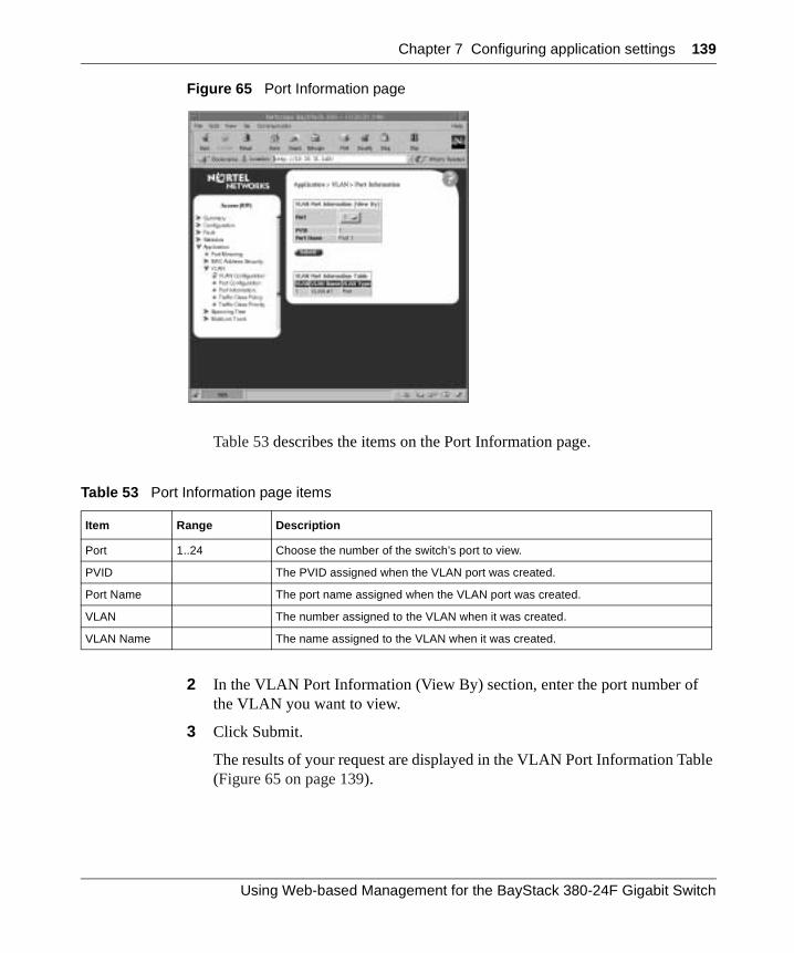
Chapter 7 Configuring application settings 139
Figure 65 Port Information page
Table 53 describes the items on the Port Information page.
2 In the VLAN Port Information (View By) section, enter the port number of the VLAN you want to view.
3 Click Submit.
The results of your request are displayed in the VLAN Port Information Table (Figure 65 on page 139).
Table 53 Port Information page items
Item Range Description
Port 1..24 Choose the number of the switch’s port to view.
PVID The PVID assigned when the VLAN port was created.
Port Name The port name assigned when the VLAN port was created.
VLAN The number assigned to the VLAN when it was created.
VLAN Name The name assigned to the VLAN when it was created.
Using Web-based Management for the BayStack 380-24F Gigabit Switch
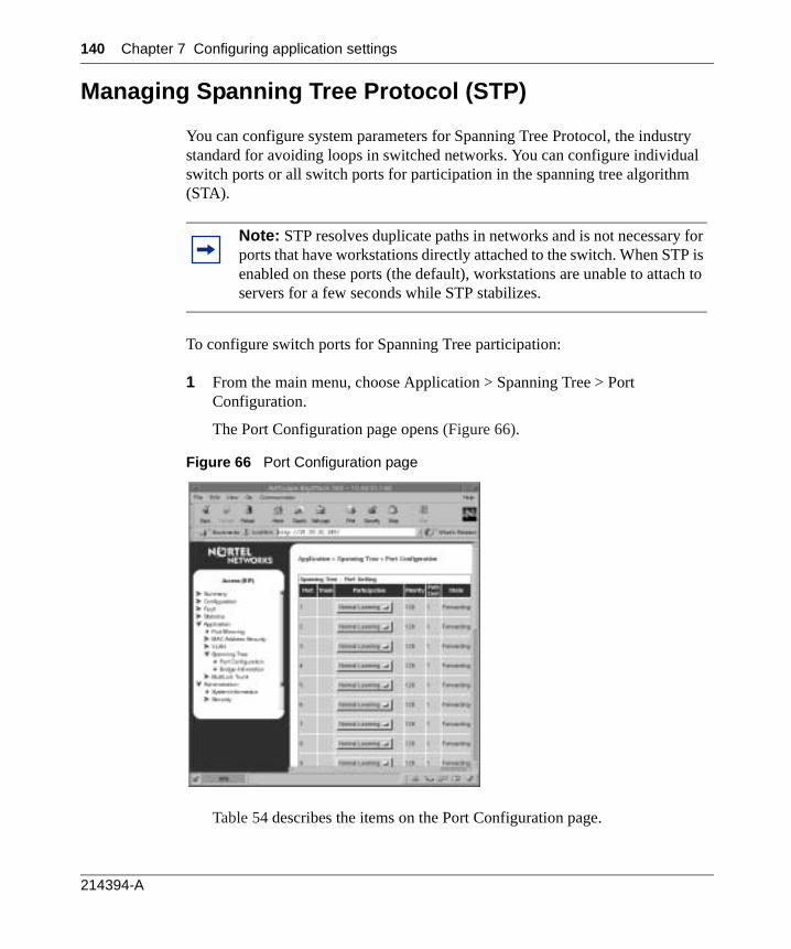
140 Chapter 7 Configuring application settings
Managing Spanning Tree Protocol (STP)
You can configure system parameters for Spanning Tree Protocol, the industry standard for avoiding loops in switched networks. You can configure individual switch ports or all switch ports for participation in the spanning tree algorithm (STA).
To configure switch ports for Spanning Tree participation:
1 From the main menu, choose Application > Spanning Tree > Port Configuration.
The Port Configuration page opens (Figure 66).
Figure 66 Port Configuration page
Table 54 describes the items on the Port Configuration page.
Note: STP resolves duplicate paths in networks and is not necessary for ports that have workstations directly attached to the switch. When STP is enabled on these ports (the default), workstations are unable to attach to servers for a few seconds while STP stabilizes.
214394-A
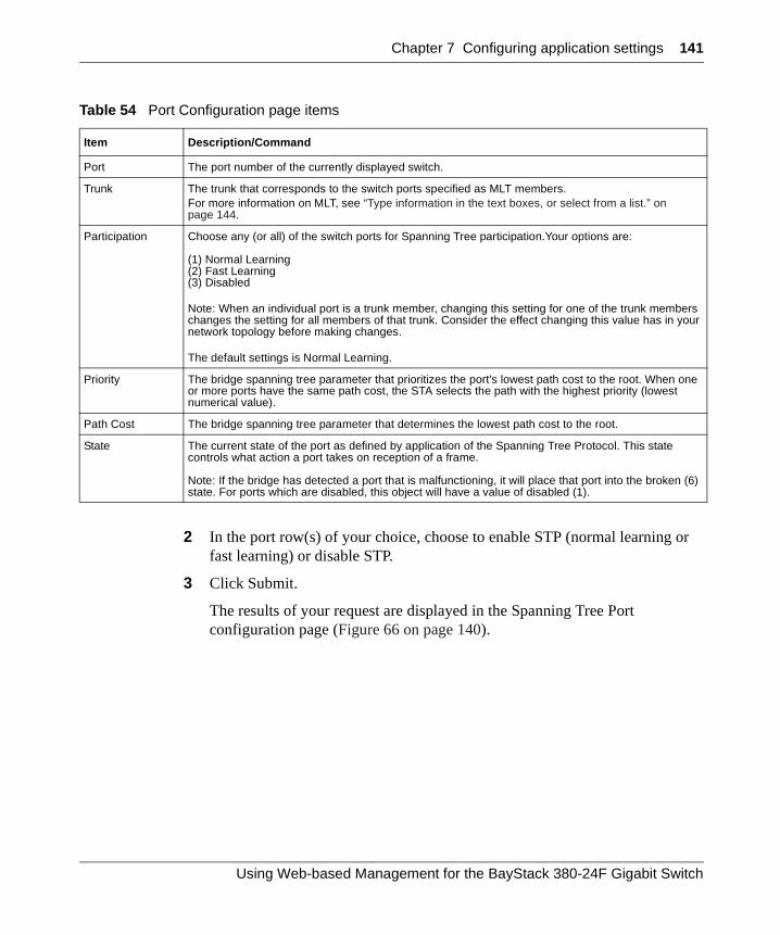
Chapter 7 Configuring application settings 141
2 In the port row(s) of your choice, choose to enable STP (normal learning or fast learning) or disable STP.
3 Click Submit.
The results of your request are displayed in the Spanning Tree Port configuration page (Figure 66 on page 140).
Table 54 Port Configuration page items
Item Description/Command
Port The port number of the currently displayed switch.
Trunk The trunk that corresponds to the switch ports specified as MLT members. For more information on MLT, see “Type information in the text boxes, or select from a list.” on page 144.
Participation Choose any (or all) of the switch ports for Spanning Tree participation.Your options are:
(1) Normal Learning(2) Fast Learning(3) Disabled
Note: When an individual port is a trunk member, changing this setting for one of the trunk members changes the setting for all members of that trunk. Consider the effect changing this value has in your network topology before making changes.
The default settings is Normal Learning.
Priority The bridge spanning tree parameter that prioritizes the port’s lowest path cost to the root. When one or more ports have the same path cost, the STA selects the path with the highest priority (lowest numerical value).
Path Cost The bridge spanning tree parameter that determines the lowest path cost to the root.
State The current state of the port as defined by application of the Spanning Tree Protocol. This state controls what action a port takes on reception of a frame.
Note: If the bridge has detected a port that is malfunctioning, it will place that port into the broken (6) state. For ports which are disabled, this object will have a value of disabled (1).
Using Web-based Management for the BayStack 380-24F Gigabit Switch
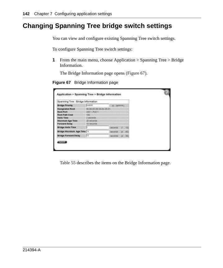
142 Chapter 7 Configuring application settings
Changing Spanning Tree bridge switch settings
You can view and configure existing Spanning Tree switch settings.
To configure Spanning Tree switch settings:
1 From the main menu, choose Application > Spanning Tree > Bridge Information.
The Bridge Information page opens (Figure 67).
Figure 67 Bridge Information page
Table 55 describes the items on the Bridge Information page.
214394-A
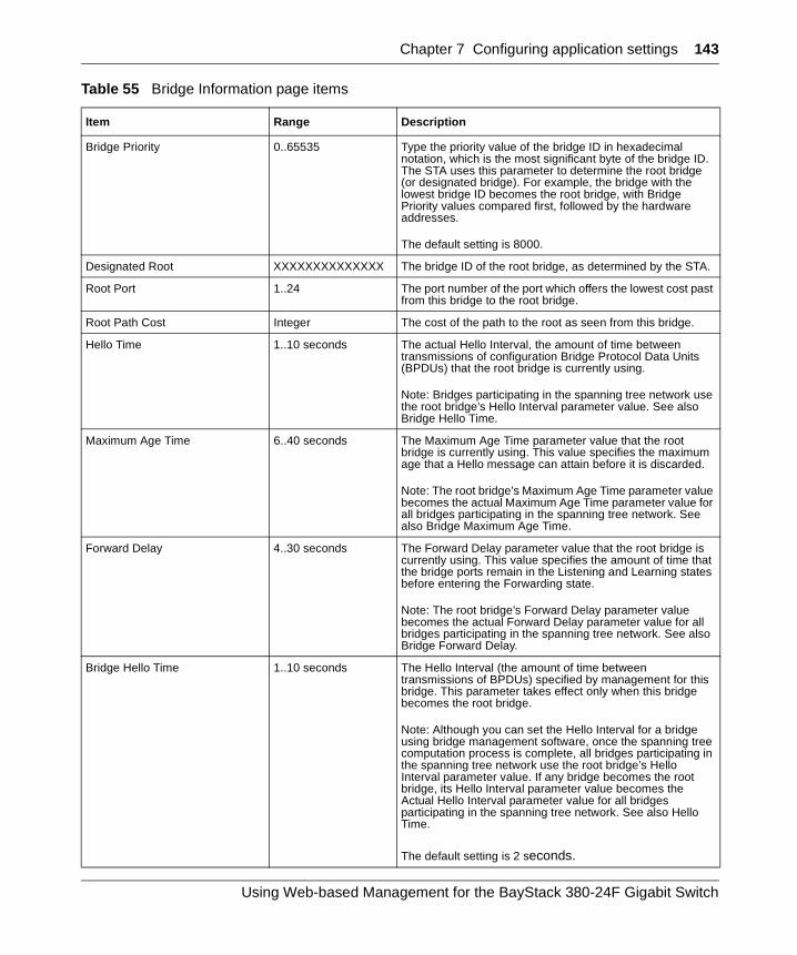
Chapter 7 Configuring application settings 143
Table 55 Bridge Information page items
Item Range Description
Bridge Priority 0..65535 Type the priority value of the bridge ID in hexadecimal notation, which is the most significant byte of the bridge ID. The STA uses this parameter to determine the root bridge (or designated bridge). For example, the bridge with the lowest bridge ID becomes the root bridge, with Bridge Priority values compared first, followed by the hardware addresses.
The default setting is 8000.
Designated Root XXXXXXXXXXXXXX The bridge ID of the root bridge, as determined by the STA.
Root Port 1..24 The port number of the port which offers the lowest cost past from this bridge to the root bridge.
Root Path Cost Integer The cost of the path to the root as seen from this bridge.
Hello Time 1..10 seconds The actual Hello Interval, the amount of time between transmissions of configuration Bridge Protocol Data Units (BPDUs) that the root bridge is currently using.
Note: Bridges participating in the spanning tree network use the root bridge’s Hello Interval parameter value. See also Bridge Hello Time.
Maximum Age Time 6..40 seconds The Maximum Age Time parameter value that the root bridge is currently using. This value specifies the maximum age that a Hello message can attain before it is discarded.
Note: The root bridge’s Maximum Age Time parameter value becomes the actual Maximum Age Time parameter value for all bridges participating in the spanning tree network. See also Bridge Maximum Age Time.
Forward Delay 4..30 seconds The Forward Delay parameter value that the root bridge is currently using. This value specifies the amount of time that the bridge ports remain in the Listening and Learning states before entering the Forwarding state.
Note: The root bridge’s Forward Delay parameter value becomes the actual Forward Delay parameter value for all bridges participating in the spanning tree network. See also Bridge Forward Delay.
Bridge Hello Time 1..10 seconds The Hello Interval (the amount of time between transmissions of BPDUs) specified by management for this bridge. This parameter takes effect only when this bridge becomes the root bridge.
Note: Although you can set the Hello Interval for a bridge using bridge management software, once the spanning tree computation process is complete, all bridges participating in the spanning tree network use the root bridge’s Hello Interval parameter value. If any bridge becomes the root bridge, its Hello Interval parameter value becomes the Actual Hello Interval parameter value for all bridges participating in the spanning tree network. See also Hello Time.
The default setting is 2 seconds.
Using Web-based Management for the BayStack 380-24F Gigabit Switch
144 Chapter 7 Configuring application settings
2 Type information in the text boxes, or select from a list.
3 Click Submit.
The bridge information is displayed in the Spanning Tree Bridge Information page (Figure 67 on page 142).
Configuring MultiLink Trunk (MLT) members
You can configure groups of links between the BayStack 380-24F Gigabit Switch and another switch or a server to provide higher bandwidth with active redundant links.
You can configure two to four switch ports together as members of a trunk to a maximum of six trunks.
Bridge Maximum Age Time 6..40 seconds The maximum age (in seconds) that a Hello message can attain before it is discarded. This parameter, specified by management for this bridge, takes effect only when the bridge becomes the root bridge.
Note: If this bridge becomes the root bridge, its Maximum Age Time parameter value becomes the Actual Maximum Age Time parameter value for all bridges participating in the spanning tree network. See also Maximum Age Time.
The default setting is 20 seconds.
Bridge Forward Delay 4..30 seconds The amount of time that the bridge ports remains in the Listening and Learning states before entering the Forwarding state.
Note: All bridges participating in the spanning tree network use the root bridge’s Forward Delay parameter value. See also Forward Delay.
The default setting is 15 seconds.
Table 55 Bridge Information page items (continued)
Item Range Description
214394-A

Chapter 7 Configuring application settings 145
To configure MultiLink Trunk members:
1 From the main menu, choose Application > MultiLink Trunk > Group.
The Group page opens (Figure 68).
Figure 68 Group page
Table 56 describes the items on the Group page.
Using Web-based Management for the BayStack 380-24F Gigabit Switch
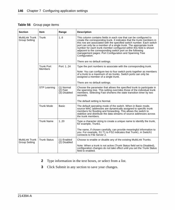
146 Chapter 7 Configuring application settings
2 Type information in the text boxes, or select from a list.
3 Click Submit in any section to save your changes.
Table 56 Group page items
Section Item Range Description
MultiLink Trunk Group Setting
Trunk 1..6 This column contains fields in each row that can be configured to create the corresponding trunk. It indicates that the trunk members in this row are associated with the specified switch number. Each switch port can only be a member of a single trunk. The appropriate trunk number for each trunk member configured within this field is shown adjacent to the corresponding switch port on the following management pages: Port Configuration and Spanning Tree Configuration.
There are no default settings.
Trunk Port Members
Port: 1..24 Type the port numbers to associate with the corresponding trunk.
Note: You can configure two to four switch ports together as members of a trunk to a maximum of six trunks. Switch ports can only be assigned a member of a single trunk.
There are no default settings.
STP Learning (1) Normal(2) Fast(3) Disabled
Choose the parameter that allows the specified trunk to participate in the spanning tree. This setting overrides those of the individual trunk members. Selecting Fast shortens the state transition timer by two seconds.
The default setting is Normal.
Trunk Mode Basic The default operating mode of the switch. When in Basic mode, source MAC addresses are dynamically assigned to specific trunk members for flooding and forwarding. This allows the switch to stabilize and distribute the data streams of source addresses across the trunk members.
Trunk Name 1..20 Type a character string to create a unique name to identify the trunk, for example, Trunk1.
The name, if chosen carefully, can provide meaningful information to you. For example, S1:T1 to FS2 indicates that Trunk1, in Switch1 connects to File Server 2.
MultiLink Trunk Group Setting
Trunk Status (1) Enabled(2) Disabled
Choose to enable or disable any of the existing MultiLink Trunks.
Note: When a trunk is not active (Trunk Status field set to Disabled), configuration changes do not take effect until you set the Trunk Status field to enabled.
214394-A
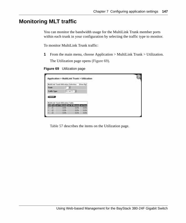
Chapter 7 Configuring application settings 147
Monitoring MLT traffic
You can monitor the bandwidth usage for the MultiLink Trunk member ports within each trunk in your configuration by selecting the traffic type to monitor.
To monitor MultiLink Trunk traffic:
1 From the main menu, choose Application > MultiLink Trunk > Utilization.
The Utilization page opens (Figure 69).
Figure 69 Utilization page
Table 57 describes the items on the Utilization page.
Using Web-based Management for the BayStack 380-24F Gigabit Switch
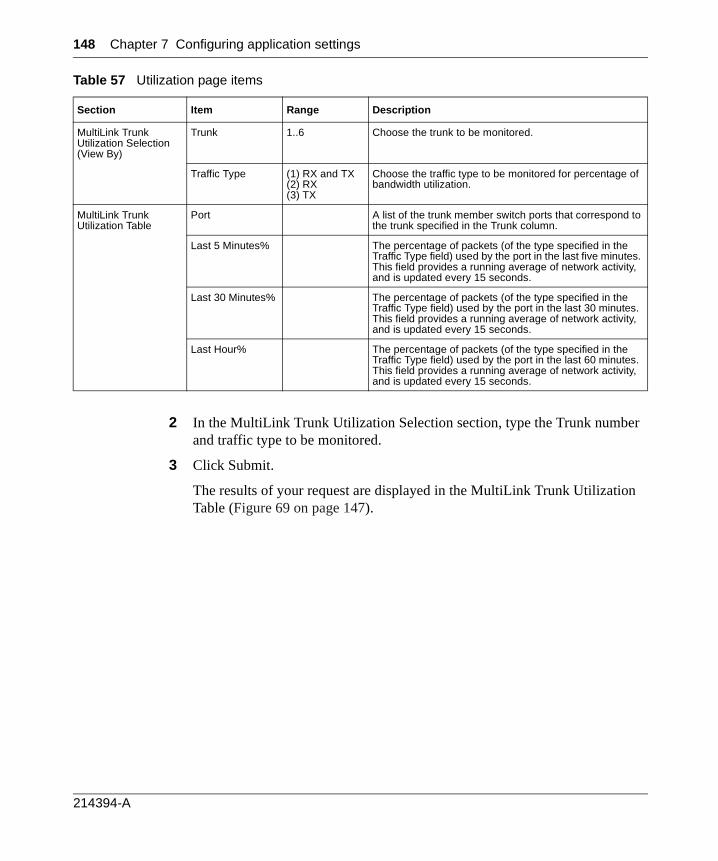
148 Chapter 7 Configuring application settings
2 In the MultiLink Trunk Utilization Selection section, type the Trunk number and traffic type to be monitored.
3 Click Submit.
The results of your request are displayed in the MultiLink Trunk Utilization Table (Figure 69 on page 147).
Table 57 Utilization page items
Section Item Range Description
MultiLink Trunk Utilization Selection (View By)
Trunk 1..6 Choose the trunk to be monitored.
Traffic Type (1) RX and TX(2) RX(3) TX
Choose the traffic type to be monitored for percentage of bandwidth utilization.
MultiLink Trunk Utilization Table
Port A list of the trunk member switch ports that correspond to the trunk specified in the Trunk column.
Last 5 Minutes% The percentage of packets (of the type specified in the Traffic Type field) used by the port in the last five minutes. This field provides a running average of network activity, and is updated every 15 seconds.
Last 30 Minutes% The percentage of packets (of the type specified in the Traffic Type field) used by the port in the last 30 minutes. This field provides a running average of network activity, and is updated every 15 seconds.
Last Hour% The percentage of packets (of the type specified in the Traffic Type field) used by the port in the last 60 minutes. This field provides a running average of network activity, and is updated every 15 seconds.
214394-A
149
Chapter 8Support menu
The customer support options available to you are:
• “Using the online Help option”, (next)
• “Downloading technical publications” on page 150
• “Upgrade option” on page 151
Using the online Help option
You can read information about Web-based management user interface functions in the online Help menu embedded in the Web-based management interface.
To open online Help:
1 From the main menu, choose Support > Help or click the Help icon located in the upper right corner of any management page.
The Online Help menu opens in a separate Web browser (Figure 70).
Using Web-based Management for the BayStack 380-24F Gigabit Switch
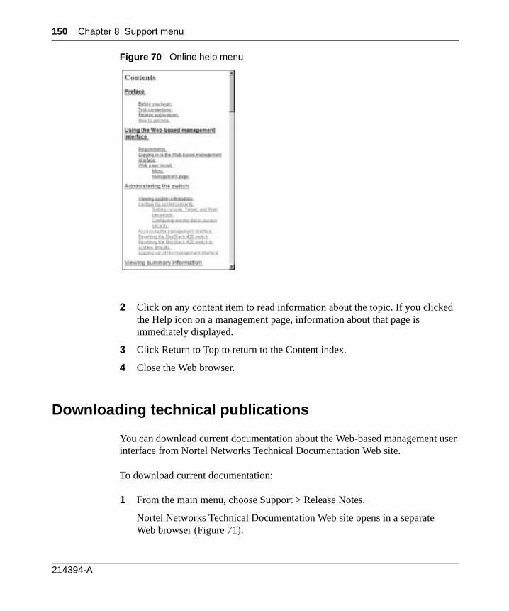
150 Chapter 8 Support menu
Figure 70 Online help menu
2 Click on any content item to read information about the topic. If you clicked the Help icon on a management page, information about that page is immediately displayed.
3 Click Return to Top to return to the Content index.
4 Close the Web browser.
Downloading technical publications
You can download current documentation about the Web-based management user interface from Nortel Networks Technical Documentation Web site.
To download current documentation:
1 From the main menu, choose Support > Release Notes.
Nortel Networks Technical Documentation Web site opens in a separate Web browser (Figure 71).
214394-A
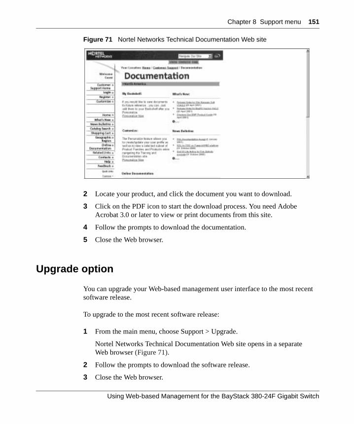
Chapter 8 Support menu 151
Figure 71 Nortel Networks Technical Documentation Web site
2 Locate your product, and click the document you want to download.
3 Click on the PDF icon to start the download process. You need Adobe Acrobat 3.0 or later to view or print documents from this site.
4 Follow the prompts to download the documentation.
5 Close the Web browser.
Upgrade option
You can upgrade your Web-based management user interface to the most recent software release.
To upgrade to the most recent software release:
1 From the main menu, choose Support > Upgrade.
Nortel Networks Technical Documentation Web site opens in a separate Web browser (Figure 71).
2 Follow the prompts to download the software release.
3 Close the Web browser.
Using Web-based Management for the BayStack 380-24F Gigabit Switch

152 Chapter 8 Support menu
214394-A

153
Index
Aaccess
SNMP 119
administrative optionslogging on 32logging out 35resetting the switch/stack 34resetting to system defaults 34security, configuring
passwords 29remote dial-in access 30
alarms, configuring 88
Allowed Source field 125
Allowed Source IP Address field 48
Allowed Source Mask field 48
application setting optionsbroadcast domains 137MultiLink Trunking (MLT) 144port mirroring 117Spanning Tree Protocol 140VLANs 132
authentication traps, enabling 49
autotopology, enabling 49
BbootP
configuring 42request modes 43
Bridge Information page 142
broadcast domains, configuring 137
Ccheck boxes, about 24
Clear by Ports page 126
community strings, configuring 49
Configuration File Download/Upload page 80
Console Password Setting page 29
Console/Communication Port page 83
conventions, text 16
Current Learning Mode field 120
customer support 17
Ddestination address filtering 119
EEntry field 122
Ethernet error statisticsviewing 109viewing in a bar graph format 111viewing in a pie chart format 111
Ethernet Errors page 109
Event Logging field 47
Ffault threshold parameters, configuring 85
Find MAC Address page 72
Ggateway addresses, configuring 42
Using Web-based Management for the BayStack 380-24F Gigabit Switch
154 Index
Group Access Rights page 58
Group Membership page 56
Group page 145
HHigh Speed Flow Control page 75
high speed flow control, configuring 75
Iicons, about 25
Inactivity Timeout field 47
Interface page 105
interface statisticsviewing 105, 106viewing in a bar graph format 108viewing in a pie chart format 107
IP addresses, configuring 42
IP page 42
LLearn by Ports page 123
logging on 32
logging out 35
Login Retries field 47
Login Timeout field 47
MMAC Address field 125
MAC address security 119allowed source 124clearing 126deleting ports 128learn by ports 123learning 121MAC DA 119ports 127security list 121
security table 124
MAC Address Security field 120
MAC Address Security SNMP-Locked field 120
MAC Address Table page 71
MAC addresseslocating a specific address 72viewing learned addresses 71
MAC DA filtering 119
main menuheadings and options 22icons 23, 25
Management Information View page 61
Microsoft Internet Explorer, software version requirements 19
MultiLink Trunking (MLT)about 144configuring 144monitoring traffic 147
NNetscape Navigator, software version
requirements 19
network administratorcontact information 44, 45
network security, protecting system integrity 20
Notification page 63
Oonline help, accessing 149
Ppasswords, setting
console 29remote dial-in access 30Telnet 29Web 29
port autonegotiation speed, configuring 74
port communication speed, configuring 83
214394-A
Index 155
Port Configuration page 127
Port Configuration page (STP) 140
Port Configuration page (VLAN) 137
Port Information page 138
Port List field 120, 122
Port List page 122
Port Lists page 121
Port Management page 74
port mirroringabout 117configuring 117
Port Mirroring page 118
Port page 99
port statisticsviewing 99, 100viewing in a bar graph format 104viewing in a pie chart format 103zeroing ports 102
product support 17
publicationshard copy 17related 16
RRadius page 30
release notes, obtaining 21
remote dial-in access, configuring 30
Reset page 34
Reset to Defaults page 34
resetting the switch/stack 34
resetting the switch/stack, to system defaults 34
RMONEthernet statistics
viewing 92viewing in a bar graph format 94viewing in a pie chart format 95
history statisticsviewing 96
viewing in a line graph format 98
RMON Ethernet page 92
RMON Event Log page 89
RMON History page 96
RMON optionsfault event log, viewing 88fault threshold parameters
configuring 85deleting 88
history statisticsviewing 96
RMON Threshold page 86
RMON, about 85
Ssecurity
MAC address-based 119
Security Configuration page 119
Security field 128
Security page 119
Security Table page 124
security, configuringpasswords 29remote dial-in access 30
SNMPabout 49MAC address security 120trap receivers
configuring 69deleting 70
SNMP Trap Receiver page 69
SNMPv1about 49configuring 49
SNMPv1 page 49
SNMPv3about 49configuring 51group access rights
Using Web-based Management for the BayStack 380-24F Gigabit Switch
156 Index
configuring 58deleting 60
group membershipconfiguring 56deleting 57
management information viewsconfiguring 60deleting 62
system information, viewing 51system notification entries
configuring 63deleting 64
target addressesconfiguring 65deleting 67
target parametersconfiguring 67deleting 69
user accessconfiguring 53deleting 55
software downloadLED indication descriptions 79process 77, 79
Software Download page 78
software version requirementsMicrosoft Internet Explorer 19Netscape Navigator 19
Spanning Tree Protocolabout 140bridge switch settings, configuring 142managing 140
Stack Information page 37
stack information, viewing 37
summary optionsviewing
stack information 37switch information 39
Support heading 21
Support menuonline help 149technical publications, downloading 150
user interface, upgrading 151
support, Nortel Networks 17
switch configuration filesnot-saved parameters 82retrieving from a TFTP server 80storing on a TFTP server 80
switch configuration optionsautotopolgy feature 49bootP settings 42community string settings 49gateway settings 42high speed flow control 75IP settings 42MAC addresses, finding 72MAC addresses, viewing 71network manager contact 44port autonegotiation speed 74port communication speed 83retrieving from a TFTP server 80SNMP trap receivers 69SNMPv3
group access rights 58management information views 60management target addresses 65management target parameters 67system information, viewing 51system notification entries 63user access 53user group membership 56
storing on a TFTP server 80switch images, downloading 77system location 44system name 44trap mode settings 49
switch images, downloading 77
switch informationviewing 39
Switch Information page 39
switch port autonegotiation speed, configuring 74
system default settings, resetting to 34
System Information page 32, 51
214394-A
Index 157
system location, naming 44
system log, viewing 90
system name, configuring 44
System page 44
system settingsmodifying 44system contact 45system location 45system name 45
system statistics options, viewingEthernet error statistics 109interface statistics 105port statistics 99transparent bridging statistics 112
Ttables and input forms, about 24
Target Address page 65
Target Parameter page 67
technical publications 17
technical publications, downloading 150
technical support 17
TELNET Access field 47
TELNET Configuration screen 46
Telnet Password Setting page 29
text conventions 16
Transparent Bridging page 112
transparent bridging statisticsviewing 112, 113viewing in a bar graph format 114viewing in a pie chart format 114
troubleshootingaddress filtering 119
Uuser interface, upgrading 151
Utilization page 147
VVLAN Configuration
Port Based modification page 130, 134Port Based Setting page 129, 133
VLAN Configuration page 132
VLANsabout 128broadcast domains, configuring 137configuring 132deleting 136MAC SA-based
configuring 131, 136port information
viewing 138port-based
about 131configuring 133
selecting a management VLAN 136
WWeb browser, requirements 19
Web Help file, accessing 21
Web Password Setting page 29
Web-based management interfacehome page, graphic 20logging in 20main menu, icons 23, 25management page 24navigating the menu 21requirements to use 19
Using Web-based Management for the BayStack 380-24F Gigabit Switch

158 Index
214394-A


