Utilizing Genetic Optimization on Buckling Restrained Braced
Frames to Evaluate the Accuracy of the Equivalent
Lateral Force Method
Kyle Scott Atwood
A project submitted to the faculty of
Brigham Young University
in partial fulfillment of the requirements for the degree of
Master of Science
Paul W. Richards, Chair
Rick J. Balling
Fernando Fonseca
Department of Civil and Environmental Engineering
Brigham Young University
April 2014
Copyright © 2014 Kyle Scott Atwood
All Rights Reserved
ABSTRACT
Utilizing Genetic Optimization on Buckling Restrained Braced
Frames to Evaluate the Accuracy of the Equivalent
Lateral Force Distribution
Kyle Scott Atwood
Department of Civil and Environmental Engineering, BYU
Master of Science
A study was performed to determine the optimal brace distribution for tall buckling
restrained braced frames under lateral seismic loading. Optimal designs were found using a
genetic algorithm in the open source software known as OpenSees. The optimum designs were
compared and a distribution of braces sizes was determined that can be used in place of the
method known as the equivalent lateral force procedure. The distributions behave better than the
ELF procedure design by lowering the story drift and reducing the total core area of all the
braces in the structure. Nine, twelve and eighteen story structures were used in this study.
Keywords: Kyle Scott Atwood, genetic optimization, seismic, ELF
ACKNOWLEDGEMENTS
This work was possible due to the support from Dr. Paul W. Richards in the Civil and
Environmental Engineering department in the Ira A. Fulton College of Engineering and
Technology at Brigham Young University. Lukas Balling, Graham Oxborrow, Eric Hoffman and
Chris Yeates provided substantial contributions to the genetic algorithm used and programmed in
OpenSees as part of previous research. I would also like to thank Dr. Richard J. Balling, and Dr.
Fernando S. Fonseca for all of the help and knowledge that they have provided to me. Finally I
would like to thank my wife, Stephanie, for the encouragement and support extended to me
throughout the duration of this research.
v
TABLE OF CONTENTS
LIST OF FIGURES ................................................................................................................... viii
1 Introduction ........................................................................................................................... 1
2 Previous Research ................................................................................................................. 3
3 Optimization Phase ............................................................................................................... 5
3.1 Optimization Results ....................................................................................................... 5
3.2 Equivalent Lateral Force Method ................................................................................... 9
4 Distribution .......................................................................................................................... 13
5 Analysis Under Suites ......................................................................................................... 19
6 Discussion of Results ........................................................................................................... 23
6.1 Possible Future Work .................................................................................................... 24
REFERENCES ............................................................................................................................ 25
Appendix A. Source Code ....................................................................................................... 27
A.1 Input ARM Distribution for 9-Stories .............................................................................. 27
A.2 Template .......................................................................................................................... 31
A.3 Main Program .................................................................................................................. 40
Appendix B. Frame Calculations ........................................................................................... 51
B.1 Column Design for ARM Distribution 9-Stories ............................................................. 51
B.2 Building and P-Delta Column Design for 9-Stories ........................................................ 52
vi
LIST OF TABLES
Table 4-1: Brace size distribution based on the first story brace size. ...................................14
Table 4-2: Brace size for all three heights and methods. .......................................................17
Table 5-1: Maximum, minimum and spread displacements for 9-stories. ............................21
Table 5-2: Maximum, minimum and spread displacements for 12-stories. ..........................22
Table 5-3: Maximum, minimum and spread displacements for 18-stories. ..........................22
viii
LIST OF FIGURES
Figure 3-1: Average of the top five optimized brace areas for 9-stories. ..............................6
Figure 3-2: Average of the top five optimized brace areas for 12-stories. ............................6
Figure 3-3: Average of the top five optimized brace areas for 18-stories. ............................7
Figure 3-4: Normalized average of the top five braced designs for 9-stories. .......................8
Figure 3-5: Normalized average of top five brace designs for 12-stories..............................8
Figure 3-6: Normalized average of top five brace designs for 18-stories..............................9
Figure 3-7: Brace areas for all three ground motions and the ELF method for 9-stories. .....10
Figure 3-8: Brace areas for all three ground motions and the ELF method for 12-stories. ...10
Figure 3-9: Brace areas for all three ground motions and the ELF method for 18-stories. ...11
Figure 4-1: Brace sizes of the different distributions for 9-stories. .......................................14
Figure 4-2: Brace sizes of the different distributions for 12-stories. .....................................15
Figure 4-3: Brace sizes of the different distributions for 18-stories. .....................................16
Figure 5-1: Story displacements for each distribution under both suites for 9-stories. .........20
Figure 5-2: Story displacements for each distribution under both suites for 12-stories. .......20
Figure 5-3: Story displacements for each distribution under both suites for 18-stories. .......21
1
1 INTRODUCTION
Where earthquake and wind loads occur, lateral force resisting systems are required to
support a structure. These lateral force resisting systems in steel buildings commonly consist of
moment frames or braced frames. Moment frames rely on stiffness from the connections and
members in the frame to resist forces; they provide ductility, while also removing unsightly
diagonal braces. Braced frames use a diagonal member to resist lateral forces and are more
economical and stiff. An increasingly popular and efficient system is that of buckling restrained
braces (BRBs). A BRB comprises of a steel core encased by an outer shell that resists global
buckling; this design allows the core to deform inelastically in both tension and compression
under high lateral loading while retaining its strength.
The design of these lateral force resisting systems can be accomplished by time history
analysis. Time history analysis looks at a previously recorded ground motion, and utilizing the
numerical integration of the equation of motion, calculates the response of a structure to that
specific ground motion. Nonlinear time history analysis provides maximum displacements along
with all other displacements as the building is subjected to ground motion (Hamburger, 2009).
The leading variable when designing a buckling restrained braced frame (BRBF) is the
cross sectional area of the brace’s core. The core area drives the cost of a BRB and therefore
should be reduced to what is needed to ensure a safe structure. These areas can be reduced to
their optimum by using genetic algorithms. Genetic algorithms are used to find optimum designs
by implementing the evolutionary process. Using the information obtained from a nonlinear time
2
history analysis in a genetic algorithm can lead to the optimization of a structure’s lateral force
resisting system under previously recorded earthquakes.
A common method for determining the size of the core areas required is known as the
equivalent lateral force method (ELF). This method is well known and often used due to its ease
of computation. This method calculates the total base shear of a structure and then, based on
floor weights and heights, distributes a portion of that base shear force to each level of the
structure according to code set forth in ASCE-7 (2010). This paper presents a method for
distributing lateral forces on a taller structure in order to minimize story drift while reducing total
brace area. This is to be accomplished by obtaining optimum designs from nonlinear time history
analysis performed within a genetic algorithm. The distribution will be verified under suites of
earthquakes to determine the accuracy of the method.
3
2 PREVIOUS RESEARCH
This research is a continuation of previous findings in this field. Balling, Balling and
Richards (2009) presents a new method for the design of buckling-restrained braced frames that
utilizes a genetic optimization algorithm and time history analysis. Their method is compared to
the equivalent lateral force procedure and their results are embodied in design curves that can be
used for quick design. Their work was focused on 1-, 3- and 5-story buildings and they found
that the optimum variation is mostly linear which is not predicted by the equivalent lateral force
procedure.
Time history analysis performed within a genetic algorithm optimization program takes a
considerable large amount of time and may not converge to the true optimum each time.
Hoffman and Richards (2013) presents a study that evaluates different techniques implemented
in genetic optimization algorithms and the results they produce. They used a nine story buckling
restrained braced frame that was being optimized to minimize brace area under seismic loading.
The optimization program used nonlinear time history analysis as its tool to determine the
efficiency of a design. It was shown that the true optimum was not converged to using a typical
genetic algorithm. Implementing forced diversity, mutation and cross over led to the
convergence to the same optimum regardless of the initial design and overall time to reach this
optimum was reduced.
4
Oxborrow G. (2009) optimizes 3-, 6-, 9-, 12- and 18-story buildings comprising of a
BRBF design and compares the optimized distribution of brace areas at each floor to the
distribution reached when utilizing the ELF method. The optimization program was developed
and refined by the two studies mentioned before this one in a software program entitled
OpenSEES developed by the Pacific Earthquake Engineering Research Center.
Weight of steel drives the cost of a steel building and as such brace areas are often
optimized in order to reduce them; however, other factors exist in reducing the overall weight of
a steel structure. Yeates C. expanded to work completed by the previous three studies and
considered multiple design objectives in the optimization program. Brace area along with
column demands were optimized in order to reduce the necessary steel required to satisfy drift
restraints. It was found that by minimizing brace areas, base column demands were minimized
but brace areas cannot be minimized by minimizing base column demands.
5
3 OPTIMIZATION PHASE
3.1 Optimization Results
The goal for the optimization phase of this project was to find the optimum designs of
BRBFs under particular ground motions and identify the trends and consistencies in order to
implement these in a new distribution of forces similar to the ELF method. Three earthquake
ground motion records were used to optimize the brace areas of 9-, 12- and 18-story buildings.
The optimization was accomplished within the OpenSees software and the source code was
developed in conjunction with the studies mentioned in the “Previous Research” portion of this
paper. An exhaustive explanation of this optimization program has been addressed previously
and therefore will not be addressed in this paper.
The three ground motions considered in this part of the study were the 1979 Imperial
Valley (El Centro), 1989 Loma Prieta (Hollister City Hall) and 1994 Northridge (Canoga Park)
records. The building parameters in addition to the three heights were; 100 feet by 100 feet
building footprint, 15 feet tall and 25 feet wide bays and a single column of bays on each side of
the building contained a single BRB in each bay.
The genetic algorithm produces the top 100 optimal designs. The top five designs were
considered and the average brace area at each level for the three different heights and ground
6
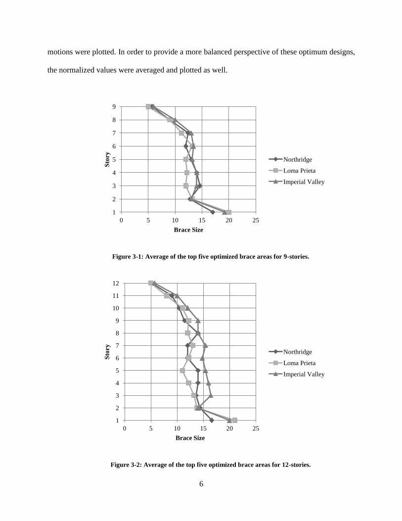
motions were plotted. In order to provide a more balanced perspective of these optimum designs,
the normalized values were averaged and plotted as well.
Figure 3-1: Average of the top five optimized brace areas for 9-stories.
Figure 3-2: Average of the top five optimized brace areas for 12-stories.
1
2
3
4
5
6
7
8
9
0 5 10 15 20 25
Sto
ry
Brace Size
Northridge
Loma Prieta
Imperial Valley
1
2
3
4
5
6
7
8
9
10
11
12
0 5 10 15 20 25
Sto
ry
Brace Size
Northridge
Loma Prieta
Imperial Valley
7
Figure 3-3: Average of the top five optimized brace areas for 18-stories.
1
2
3
4
5
6
7
8
9
10
11
12
13
14
15
16
17
18
0 5 10 15 20 25
Sto
ry
Brace Size
Northridge
Loma Prieta
Imperial Valley
8
Figure 3-4: Normalized average of the top five braced designs for 9-stories.
Figure 3-5: Normalized average of top five brace designs for 12-stories.
1
2
3
4
5
6
7
8
9
0% 5% 10% 15% 20%
Sto
ry
Brace Size
Northridge
Loma Prieta
Imperial Valley
1
2
3
4
5
6
7
8
9
10
11
12
0% 5% 10% 15% 20%
Sto
ry
Brace Size
Northridge
Loma Prieta
Imperial Valley
9
Figure 3-6: Normalized average of top five brace designs for 18-stories.
3.2 Equivalent Lateral Force Method
The equivalent lateral force method is the current design practice for preliminary and
often final design for lateral force resisting systems. In order to provide a comparison to these
optimum designs, the ELF method was applied to the three different story heights and brace
areas were obtained.
1
2
3
4
5
6
7
8
9
10
11
12
13
14
15
16
17
18
0% 5% 10% 15%
Sto
ry
Brace Size
Northridge
Loma Prieta
Imperial Valley
10
Figure 3-7: Brace areas for all three ground motions and the ELF method for 9-stories.
Figure 3-8: Brace areas for all three ground motions and the ELF method for 12-stories.
1
2
3
4
5
6
7
8
9
0 5 10 15 20 25
Sto
ry
Brace Size
Northridge
Loma Prieta
Imperial Valley
ELF
1
2
3
4
5
6
7
8
9
10
11
12
0 5 10 15 20 25
Sto
ry
Brace Size
Northridge
Loma Prieta
Imperial Valley
ELF
11
Figure 3-9: Brace areas for all three ground motions and the ELF method for 18-stories.
1
2
3
4
5
6
7
8
9
10
11
12
13
14
15
16
17
18
0 5 10 15 20 25
Sto
ry
Brace Size
Northridge
Loma Prieta
Imperial Valley
ELF
13
4 DISTRIBUTION
The ELF method calculates a base shear force for the entire building. The force of the
base shear is a function of many factors but some of the more notable ones are location, weight,
height and the type of lateral force resisting system. This base shear is divided and then
distributed to each story of the building; the magnitude of the force depends upon the height and
weight of the floor in question relative to the overall height and weight of the building.
Comparative to the ELF method, two distributions were developed in part of this
research. The first is based off of the actual brace areas found from the optimization phase of this
project while the second is a result from the behavior of the normalized areas. The first
distribution is called the Atwood Richards Method (ARM) and the second is called Distribution
1 (DIST). Each distribution is based off of the lowest level brace size, which must have enough
capacity to meet the demands of the calculated base shear of the building. The base shear is
calculated the same way as prescribed in ASCE-7 (2010). The ARM contains a zigzag pattern for
the lower story braces, holds constant in the middle and slowly tapers down in the highest
stories. DIST is a simpler design, brace areas drop after the initial brace size and remain constant
for three stories and then the size is reduced again and the highest stories have the same
distribution as the ARM (see Table 4-1).
14
Table 4-1: Brace size distribution based on the first story brace size.
Story
1 2 3 4 5 6* 7 8 9
Method DIST n n-3 n-3 n-3 n-3 .667n .583n .5n .33n
ARM n n-5 n-2 n-5 n-3 .667n .583n .5n .33n
*This story is repeated as the number of stories increases.
Figure 4-1: Brace sizes of the different distributions for 9-stories.
1
2
3
4
5
6
7
8
9
0 2 4 6 8 10 12 14 16
Sto
ry
Brace Size
ELF
ARM
DIST
15
Figure 4-2: Brace sizes of the different distributions for 12-stories.
1
2
3
4
5
6
7
8
9
10
11
12
0 2 4 6 8 10 12 14 16
Sto
ry
Brace Size
ELF
ARM
DIST
16
Figure 4-3: Brace sizes of the different distributions for 18-stories.
The ARM and DIST distributions provide brace area savings from 10% up to 14% when
compared to the brace areas calculated by the ELF method. This reduces the weight and cost of
these braced frames.
1
2
3
4
5
6
7
8
9
10
11
12
13
14
15
16
17
18
0 2 4 6 8 10 12 14 16 18
Sto
ry
Brace Size
ELF
ARM
DIST
17
Table 4-2: Brace size for all three heights and methods.
Method and Brace Size
Story ELF ARM DIST ELF ARM DIST ELF ARM DIST
18 17 17 17
17 17 12 14
16 17 15 14
15 16 12 14
14 16 14 14
13 16 11 11
12 16 11 11 15 15 15
11 16 11 11 15 10 12
10 15 11 11 15 13 12
9 15 11 11 15 10 12 14 14 14
8 14 11 11 14 12 12 14 9 11
7 13 11 11 14 10 10 14 12 11
6 12 11 11 13 10 10 13 9 11
5 11 11 11 11 10 10 12 11 11
4 9 11 11 10 10 10 11 9 9
3 7 10 10 8 9 9 9 8 8
2 5 9 9 6 8 8 7 7 7
1 3 6 6 3 5 5 4 5 5
Total 235 205 208 139 122 125 98 84 87
19
5 ANALYSIS UNDER SUITES
In order to analyze these distributions a time history analysis must be run for each
distribution under the same ground motions and scaled appropriately. For each distribution at the
three building heights the designs were subjected to time history analysis under two suites of 20
ground motion records each. These two suites shall be referred to as Long and Short. Long is
applicable to buildings with a long building period and Short to buildings with a short building
period.
The building model for these tests was altered from the original optimization model in
order to coincide with parallel research. The story heights remained the same while the bay
widths were increased to 30 feet. Instead of a single brace configuration a chevron configuration
with two braces in each bay was used. Another bay was added increasing the building footprint
and making a total of five bays on each face of the structure. The maximum displacements for
each story were recorded for each ground motion in the suite. The median and 85th
percentile
was then calculated for each level under all of the ground motion records in the suite. The range
of displacements was also calculated for each distribution at each building height.
20
Figure 5-1: Story displacements for each distribution under both suites for 9-stories.
Figure 5-2: Story displacements for each distribution under both suites for 12-stories.
1
2
3
4
5
6
7
8
9
1 1.5 2 2.5 3 3.5 4 4.5 5
Sto
ry
Story Displacement (in)
ELF Short
DIST Short
ARM Short
ELF Long
DIST Long
ARM Long
Drift Limit
1
2
3
4
5
6
7
8
9
10
11
12
1 2 3 4 5 6
Sto
ry
Story Displacement (in)
ELF Short
DIST Short
ARM Short
ELF Long
DIST Long
ARM Long
Drift Limit
21
Figure 5-3: Story displacements for each distribution under both suites for 18-stories.
Table 5-1: Maximum, minimum and spread displacements for 9-stories.
9 Stories
Min Max Spread
ELF Short 1.52 3.35 1.83
DIST Short 1.83 3.02 1.19
ARM Short 1.93 3.43 1.50
ELF Long 1.88 4.66 2.79
Dist Long 1.58 4.05 2.46
ARM Long 1.60 4.21 2.60
1
2
3
4
5
6
7
8
9
10
11
12
13
14
15
16
17
18
1 2 3 4 5 6 7
Sto
ry
Story Displacement (in)
ELF Short
DIST Short
ARM Short
ELF Long
DIST Long
ARM Long
Drift Limit
22
Table 5-2: Maximum, minimum and spread displacements for 12-stories.
12 Stories
Min Max Spread
ELF Short 1.54 5.51 3.97
DIST Short 1.84 3.38 1.54
ARM Short 1.81 3.85 2.04
ELF Long 1.56 4.91 3.35
Dist Long 1.81 3.67 1.86
ARM Long 1.80 4.33 2.53
Table 5-3: Maximum, minimum and spread displacements for 18-stories.
18 Stories
Min Max Spread
ELF Short 1.97 6.45 4.47
DIST Short 2.01 3.63 1.62
ARM Short 1.99 3.51 1.53
ELF Long 2.23 5.97 3.74
Dist Long 2.06 4.32 2.27
ARM Long 2.05 4.17 2.13
23
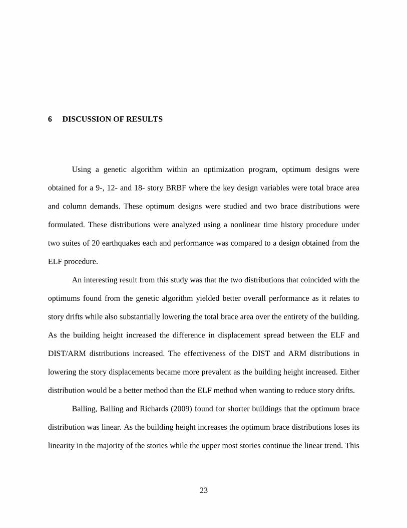
6 DISCUSSION OF RESULTS
Using a genetic algorithm within an optimization program, optimum designs were
obtained for a 9-, 12- and 18- story BRBF where the key design variables were total brace area
and column demands. These optimum designs were studied and two brace distributions were
formulated. These distributions were analyzed using a nonlinear time history procedure under
two suites of 20 earthquakes each and performance was compared to a design obtained from the
ELF procedure.
An interesting result from this study was that the two distributions that coincided with the
optimums found from the genetic algorithm yielded better overall performance as it relates to
story drifts while also substantially lowering the total brace area over the entirety of the building.
As the building height increased the difference in displacement spread between the ELF and
DIST/ARM distributions increased. The effectiveness of the DIST and ARM distributions in
lowering the story displacements became more prevalent as the building height increased. Either
distribution would be a better method than the ELF method when wanting to reduce story drifts.
Balling, Balling and Richards (2009) found for shorter buildings that the optimum brace
distribution was linear. As the building height increases the optimum brace distributions loses its
linearity in the majority of the stories while the upper most stories continue the linear trend. This
24
could be a result from higher mode shapes playing a larger role in the response of the building to
the ground motions.
6.1 Possible Future Work
This researched focused on a typical structure and primarily the two distributions
developed. The following is a list of areas that can be considered beyond the basic outline
presented in this study and areas that require further research.
1. Consider other distributions that perform better under the suites of earthquakes.
2. Develop the nonlinear time history analysis code to record maximum column
demands and observe the behavior of the frames designed by the ELF method
compared to other distributions.
3. Look into the dynamic response of the building using the equation of motion in order
to explain why the optimum designs contain certain properties as the building height
increases.
4. Perform physical testing in order to verify that the distributions discovered in this
research do perform as predicted.
25
REFERENCES
AISC. AISC 341, Seismic provisions for structural steel buildings. Chicago, IL: American Institute of
Steel Construction Inc., 2012.
ASCE. ASCE 7-10, Minimum design loads for buildings and other structures. Reston, VA: American
Society of Civil Engineering, 2010.
Balling, L. J. "Design of buckling-restrained braced frames using nonlinear time history analysis and
optimization." Master's Thesis. Provo, UT: Brigham Young University, 2007.
Balling, R. J. Computer Analysis and Optimization of Structures. Provo, UT: BYU Academic
Publishing, 2006.
Balling, R. J., L. J. Balling, and P. W. Richards. "Design of buckling restrained braced frames using
nonlinear time history analysis and optimization." Journal of Structural Engineering 135, no.
5 (May 2009): 461-468.
Hamburger, Ronald O. Facts for steel buildings: Earthquakes and seismic design. American Institute
of Steel Construction, 2009.
Hoffman, E. and Richards, P. (2014). "Efficiently Implementing Genetic Optimization with
Nonlinear Response History Analysis of Taller Buildings." Journal of Structural
Engineering, 17 (March 2014): A4014011.
Oxborrow, G. “Optimized Distribution of Strength in Buckling-Restrained Braced Frames in
Tall Buildings.” MS Thesis, Provo, UT: Brigham Young University, 2009.
27
APPENDIX A. SOURCE CODE
The following pages contain a typical input file, template file and main program file for
the non linear time history analysis program for a suite of earthquakes.
A.1 Input ARM Distribution for 9-Stories
#This is an input file that defines parameters used to generate modes.
#The same input file can be used in conjunction with static.tcl,
#dynamic.tcl, and pushover.tcl to perform different kinds of analyses
#on the same systems.
#
#Files that will be referenced
source Template42/template42.tcl
source Template12/template12.tcl
source OtherProcedures/generalProcedures.tcl
source OtherProcedures/combinedTemplates.tcl
source OtherProcedures/postProcessing.tcl
source OtherProcedures/rotationSpringParameters.tcl
source OtherProcedures/LookupShapeProp.tcl
28
#variables that specify file locations
set filename "OtherProcedures/AISC_Database.csv"
set GMdir "GMfiles"
set dataDir "Results"
#General variables that typically apply to multiple templates
set numFrames 1
set numStories 9
set storyHeights [list [expr 15*12] [expr 15*12] [expr 15*12]\
[expr 15*12] [expr 15*12] [expr 15*12]\
[expr 15*12] [expr 15*12] [expr 15*12]]
set bayWidth [expr 30*12]
set Es 29000
set Fy 50
set columnTransfCode 1; #0 is linear, 1 is P-Delta, 2 is corotational
set beamTransfCode 1; #0 is linear, 1 is P-Delta, 2 is corotational
#All of the templates used to define the system
set diffTemplates [list 42 12]
29
#Loads for P-Delta effects
set colLoad -521; #should be -1022 for Daniels study.
set colPointLoads [list $colLoad $colLoad $colLoad $colLoad $colLoad $colLoad
$colLoad $colLoad $colLoad]
#Specific properties for template 41 (p-delta columns)
#set pDeltacolAreas [list 1000 1000 1000 1000 1000 1000]; #add an entry for every story
#set pDeltacolIs [list 1 1 1 1 1 1]; #add an entry for every story
#set pDeltacolZx [list 448 448 448 196 196 196]; #add an entry for every story
set storyHeight [expr 15.0*12]
set pDeltacolAreas [list 272 272 272 272 168 168 140 140 99]; #add an entry for every
story
set pDeltacolIs [list 7273 7273 7273 7273 3602 3602 3602 3602 1874]; #add an entry for
every story
set pDeltacolZx [list 9000 9000 9000 9000 9000 9000 9000 9000 9000]; #add an entry
for every story
set pDeltacolumnProps [list $pDeltacolAreas $pDeltacolIs $pDeltacolZx]
set pDeltacolumnFixity 0; #0 is pinned at base, 1 is fixed
#Specifiy properties for template 12 (single bay chevron BRBF)
30
set numFrames12 1
set baseFixity12 0; #0 pinned, 1 fixed
set beamFixity12 0; #0 pinned, 1 fixed
set colShapes [list W14X311 W14X311 W14X211 W14X211 W14X132 W14X132
W14X68 W14X68 W14X48];
#these are the columns sizes at each story. Use upper-case X.\
There should be (number of stories) columns in the list.
set columnProps12 [LookupShapeProp $filename $colShapes];
set beamShapes [list W14X48 W14X48 W14X48 W14X48 W14X48 W14X48 W14X48
W14X48 W14X48];
#These are beam sizes at each story
set beamProps12 [LookupShapeProp $filename $beamShapes]
set brAreas12 [list 14 9 12 9 11 9 8 7 5]; #this is the primary design
set brIs12 [list 300 300 300 300 300 300 300 300 300]; #not used
set brZx12 [list 300 300 300 300 300 300 300 300 300]; #not used
set braceProps12 [list $brAreas12 $brIs12 $brZx12]
#brace parameters
set Fyb 38
set b_Brace 0.003
set R0_Brace 20;
31
set cR1_Brace 0.925; # parameter for the change of R with cyclic loading history
set cR2_Brace 0.15; # parameter for the change of R with cyclic loading history
set stiffnessFactor 1.6; #accounts for nonuniform core area
set a1 0.065
set a2 1
set a3 0.045
set a4 1
#Defining the masses (not required for pushover or static analyses)
set sameStoryMass 1.532;
set storyMasses [list $sameStoryMass $sameStoryMass $sameStoryMass\
$sameStoryMass $sameStoryMass
$sameStoryMass $sameStoryMass $sameStoryMass $sameStoryMass]
set templateForMasses 42
#Defining the template used for the drift recorders
set driftTemplate 42
A.2 Template
# -----------------------------------------------------------------------------
#
# template41nodesAndElements
32
#
# Template 41 is for a P-Delta column.
# Template 41 is a simpler version of template 42 that does not include
# yielding springs (just elastic beam-column elements)
# Determines the coordinates for all the nodes for the 41 template.
# Uses OpenSees node command to define them.
# Defines beam elements
#
#
# Arguments:
#numStories the number of stories in the frame
#storyHeights list will all of the story heights (in inches)
#Es modulus of elasticity for steel
#Fy yield strength of beams and columns
#columnProps a list with lists of column properties
#columnTransfCode indicates the type of geometric transformation\
for the column elements(0 linear, 1 pdelta)
#fixity 0=pinned, 1=fixed at the base; should be pinned if being
#used as a p-delta column; may be fixed to do simple
#system studies.
#
# Results:
#Sends out commands to define the node coordinates and\
33
elements in OpenSees
#
#
# Author:
#Paul Richards, adapted from template42 on 8/6/13
#
proc template42nodesAndElements {numStories storyHeights\
Es Fy columnProps\
columnTransfCode\
fixity} {
set template 42
#######################################################################
#preparatory stuff so that the beam and column elements can be defined
set columnAreas [lindex $columnProps 0]
set columnIs [lindex $columnProps 1]
###############################################################
#info for geometric transformation, same for all procedures
set columnTransfTag [expr $template*100 + 0]; #0 is for columns
if {$columnTransfCode==0} {
geomTransf Linear $columnTransfTag;
34
} elseif {$columnTransfCode==1} {
geomTransf PDelta $columnTransfTag;
} else {
geomTransf Corotational $columnTransfTag;
}
########################################################################
#need to generate the locations for the x-grids and y-grids
set ygridElevations 0
set cumElevation 0
foreach height $storyHeights {
set cumElevation [expr $cumElevation + $height]
lappend ygridElevations $cumElevation
}
set frameNum 1
#Define the base nodes in the 0 plane and fix those at y-grid 0
set ygrid 0
set Y [lindex $ygridElevations $ygrid];
set X 0
set xgrid 0
set plane 0
set nodeID [expr $template*100000000 + $frameNum*1000000 \
35
+ $plane*10000 + $ygrid*100 + $xgrid]
node $nodeID $X $Y;
fix $nodeID 1 1 1;
#Define the column nodes (2 plane) and elements (1 plane)
for {set ygrid 0} {$ygrid < $numStories} {incr ygrid} {
set xgrid 0
set plane 2
set nodeI [expr $template*100000000 + $frameNum*1000000\
+ $plane*10000 + $ygrid*100 + $xgrid]
#this node only needs to be defined when ygrid is 0\
#for other cases it is defined by the j-node
if {$ygrid == 0} {
set X 0
set Y [lindex $ygridElevations $ygrid];
node $nodeI $X $Y;
}
set nodeJ [expr $template*100000000 + $frameNum*1000000 \
+ $plane*10000 + [expr $ygrid + 1]*100 + $xgrid]
set X 0
set Y [lindex $ygridElevations [expr $ygrid + 1]];
node $nodeJ $X $Y;
set plane 1
set elemID [expr $template*100000000 + $frameNum*1000000 \
36
+ $plane*10000 + [expr $ygrid + 1]*100 + $xgrid]
set area [lindex $columnAreas [expr $ygrid]]
set I [lindex $columnIs [expr $ygrid]]
element elasticBeamColumn $elemID $nodeI $nodeJ $area $Es\
$I $columnTransfTag
}
#Constrain the bottom column nodes to the base nodes.
set ygrid 0
set xgrid 0
set plane 2
set nodeSlave [expr $template*100000000 + $frameNum*1000000\
+ $plane*10000 + $ygrid*100 + $xgrid]
set plane 0
set nodeMaster [expr $template*100000000 + $frameNum*1000000\
+ $plane*10000 + $ygrid*100 + $xgrid]
if {$fixity==0} {
equalDOF $nodeMaster $nodeSlave 1 2
} else {
equalDOF $nodeMaster $nodeSlave 1 2 3
}
puts "node constraints defined"
puts "nodes and elements defined"
}
37
# -----------------------------------------------------------------------------
#
# template42gravity
#
# Applies gravity loads to the P-Delta column.
# Different point loads may be applied at each level.
# Uses OpenSees pattern command to define them.
# Performs gravity analysis.
#
# Arguments:
# numStories the number of stories in the frame
# colPointLoads a list of the point loads to be placed at each level
#
# Results:
# Defines and applies gravity loads
#
#
# Author:
# Paul Richards, modified from template42 on 8/6/13
#
# -----------------------------------------------------------------------------
proc template42gravity {numStories colPointLoads} {
38
set template 42
#Define the load pattern
pattern Plain 100 Constant {
set frameNum 1
set plane 2; #top of column node plane
for {set ygrid 1} {$ygrid <= $numStories} {incr ygrid} {
set xgrid 0
set nodeID [expr $template*100000000 + $frameNum*1000000 \
+ $plane*10000 + $ygrid*100 + $xgrid]
load $nodeID 0.0 [lindex $colPointLoads [expr $ygrid -1 ]] 0.0
puts "load $nodeID 0.0 [lindex $colPointLoads [expr $ygrid -1 ]] 0.0"
}
}
#Perform the static gravity analysis
set Tol 1.0e-6; # convergence tolerance for test
variable constraintsTypeGravity Plain; # default
constraints $constraintsTypeGravity; # how it handles boundary\
conditions
numberer RCM; # renumber dof's to minimize\
39
band-width (optimization),\
if you want to
system BandGeneral; # how to store and solve the \
system of equations in the\
analysis (large model:\
try UmfPack)
test NormDispIncr $Tol 6; # determine if convergence has\
been achieved at the end of\
an iteration step
algorithm Newton; # use Newton's solution algorithm:\
updates tangent stiffness at\
every iteration
set NstepGravity 1; # apply gravity in 10 steps
set DGravity [expr 1.0/$NstepGravity]; # load increment
integrator LoadControl $DGravity; # determine the next time step\
for an analysis
analysis Static; # define type of analysis static\
or transient
analyze $NstepGravity; # apply gravity
loadConst -time 0.0; # maintain constant gravity\
loads and reset time to zero
40
puts "gravity applied and analyzed"
}
A.3 Main Program
#***********************************************************************
# dynamic.tcl *
#***********************************************************************
# Description: This script is executed in OpenSees by typing "source
# dynamic.tcl" on the OpenSees command line), this script will create
# models based on templates and analyze the models under combined gravity
# and earthquake loading.
# Many comments are included since it is intended that this will be the
# users first experience with the TCL programming language and with OpenSees.
#
# Overview: This script is divided into 9 parts.
# 1. Reading in the source files for dynamic analysis procedures
# 2. Defining the parameters for the dynamic analysis
# 3. Building the P-Delta column (represents the "non-seismic" parts of bldg)
# 4. Building the seismic frames using various templates
# 5. Assigning masses and performing eigenvalue analysis
# 6. Defining damping
# 7. Defining recorders to get output
# 8. Running the dynamic analyses (with gravity loads applied)
41
# 9. Post-processing results
#***********************************************************************
# 1. Reading in the source files for inputs and dynamic analysis procedures *
#***********************************************************************
# Description: OpenSees consists of a series of pre-defined procedures that
# are used to build models and subject them to earthquake loads.
# In addition to these "built-in" procedures, custom procedures
# can be defined to assist in the definition of models and processing
# results. The commands below read in files that define custom procedures.
# For information on the procedures defined by a file, open the
# particular file in a text editor and read the comments.
source example18.tcl
source OtherProcedures/dynamicAnalysisProcedures.tcl
source OtherProcedures/combinedTemplates.tcl
source OtherProcedures/eqSuites.tcl
#source OtherProcedures/rotationalSprings.tcl
#***********************************************************************
# 2. Defining the parameters for the dynamic analysis *
42
#***********************************************************************
# Description: The variables defined below control features of the dynamic
# analyses.
set GMdir "GMfiles"; #Folder with the Ground Motion files
set suiteName "LongPeriod"; #Name of the earthquake suite to be used for
#analyses. Possible suites for use are defined
#in Other Procedures/eqSuites.tcl
set suiteList [defineSuite $suiteName]; #procedure to populate the list of GMs
set Sds 1.40; #Parameter to define a design spectra that can be
#used to scale Ground Motion files
set Sd1 0.8; #Another parameter to define a design spectra
set tLong 8; #Another parameter to define a design spectra
set periodList1 [createList 0.01 2 0.01]
set periodList2 [createList 2.1 6 0.1]
set periodList3 [createList 7.0 20 1]
set periodList [concat $periodList1 $periodList2 $periodList3]
#The Period lists above are for scaling ground motions.
set GMdirection 1; #Direction of ground acceleration, 1 means x-direction
set IDLoadTagDyn 20; #Dynamic analysis needs a unique load tag. The actual
43
#value is arbitrary. It just has to be different from
#the gravity load tag.
set IDLoadTagGravity 100; #See comment above.
set dtAnalysis 0.005; #Time step used for the analysis. Does not have to
#match the time step for the earthquake records
set dampingZeta 0.02; #Level of Rayleigh Damping assinged to the model
set extraTime 60; #This is extra time added to dynamic analysis after the
#groud acceleration stops to allow the building to stop
#vibrating so residual deformations can be measured.
#***********************************************************************
# 3. Building the P-Delta column *
#***********************************************************************
# Description: The P-Delta column represents the parts of the building that
# are not the seismic frames. It is helpful to always have it defined. If
# it turns out that the P-Delta is not needed, or if results need to be
# checked without its influence, very small properties can be assigned
# for the column cross-sections and no gravity loads can be assigned (these
# things are defined in the input.tcl file). For the dynamic analysis,
# masses will be assigned to the P-Delta column, and drift recorders at each
# level will be used to determine story drifts.
44
wipe all; # clear memory of past model definitions
model BasicBuilder -ndm 2 -ndf 3; # ndm = #dimension, ndf = #dofs
template42nodesAndElements $numStories $storyHeights\
$Es $Fy $pDeltacolumnProps\
$columnTransfCode\
$pDeltacolumnFixity
#***********************************************************************
# 4. Building the seismic frames using various templates *
#***********************************************************************
# Description: The seismic frames are defined using templates. The input.tcl
# file must source the template procudures you are going to use, and must
# provide all of the input parameters required for the templates (see
# comments in the input.tcl file).
# Any number of templates may be used.
template12 $numFrames12 $numStories $storyHeights $bayWidth $baseFixity12\
$beamFixity12 $Es\
$columnProps12 $beamProps12 $braceProps12\
$columnTransfCode $beamTransfCode\
$Fyb $b_Brace $R0_Brace $cR1_Brace $cR2_Brace $stiffnessFactor\
$a1 $a2 $a3 $a4
45
combineTemplates $numStories $diffTemplates
#***********************************************************************
# 5. Assigning masses and performing eigenvalue analysis *
#***********************************************************************
# Description: The masses are assigned at each level of the P-Delta column.
# eigenvalue analysis determines the natural period of the frames.
assignMasses $templateForMasses $numFrames $numStories $storyMasses
set naturalPeriods [periods $numStories]
set firstModePeriod [lindex $naturalPeriods 0]
#**********************************************************************
# 6. Defining damping *
#***********************************************************************
# Description: Raleigh damping is defined based on zeta in the first and third
# modes
defineDamping $dampingZeta $naturalPeriods
#***********************************************************************
46
# 7. Initialize some of the results lists *
#***********************************************************************
# Description: These lists will be populated at the system is analyzed under
# each earthquake in the suite. They need to be initialized to start
set storyNumbers [list]
for {set i 1} {$i <= $numStories} {incr i} {
lappend storyNumbers $i
}
set cumStoryDriftList $storyNumbers
set cumResidualDriftList $storyNumbers
#***********************************************************************
# 8. Running the dynamic analyses (with gravity loads applied) *
#***********************************************************************
# Description: This part of the script executes a loop that analyzes the system
# under each of the earthquakes in the suite. The basic steps for each
# earthquake are: a) determine the appropriate scale factor for the
# b) clear all previous analysis results and recorders, d) define recorders,
# e) apply the gravity loads, f) read in the earthquake record, g) do the
# dynamic analysis under the earthquake, h) remove results from OpenSees
# memory (they are recorded in the output files), i) do some post-processing
# to identify maximum responses from the particular earthquake, prior to the
# output files being overwritten by the next earthquake. These steps are
47
# repeated for every earthquake record in the suite.
foreach GM $suiteList {
# (a)
set earthquakeSpectra [readEarthquakeSpectraCustom $GM]
set period [lindex $earthquakeSpectra 0]
set acc [lindex $earthquakeSpectra 1]
# (b)
set scaleFactor [computeScalingFactor $earthquakeSpectra
$firstModePeriod $Sd1 $Sds $tLong ]
#set scaleFactor [expr 1.5*$scaleFactor]; #uncomment for MCE
puts "scaleFactor is: $scaleFactor"
# (c)
reset;
wipeAnalysis;
remove recorders;
# (d)
48
setupStoryDriftRecorders $dataDir $numStories $driftTemplate;
#template32recorders $numFrames $numStories
#template02recorders $numFrames $numStories $dataDir
template12recorders $numFrames $numStories $dataDir
# (e)
template42gravity $numStories $colPointLoads
# (f)
set inFilename "GMfiles/$GM.AT2"
set outFilename "GMfiles/$GM.dat"
ReadRecord $inFilename $outFilename dt nPts
puts "dt is $dt"
puts "nPts is $nPts"
# (g)
source OtherProcedures/dynamicAnalysisSettings.tcl
runDynamicAnalysis $scaleFactor $GM $GMdirection $IDLoadTagDyn\
$nPts $dtAnalysis $dt $IDLoadTagGravity $extraTime
# (h)
wipeAnalysis;
49
remove recorders;
# (i)
set driftSummaries [findMaxFromOut $numStories $dataDir storydrift]
set storyDrifts [lindex $driftSummaries 0]
set residualDrifts [lindex $driftSummaries 1]
puts "story drift is: $storyDrifts"
puts "residual drifts are: $residualDrifts"
set cumStoryDriftList [cumStoryDrifts $numStories $storyDrifts $cumStoryDriftList]
set cumResidualDriftList [cumStoryDrifts $numStories $residualDrifts
$cumResidualDriftList]
puts "cumStoryDriftList: $cumStoryDriftList"
puts "cumResidualDriftList: $cumResidualDriftList"
}
#***********************************************************************
# 9. Post-processing results
#***********************************************************************
# Description: After the system has been analyzed under each earthquake, and
# maximum responses have been identified, median and 85th percentile values
# can be calculated. At the end, the wipe all command removes the model from
50
# memory.
set avgStoryDriftList [avgStoryDrifts $cumStoryDriftList $numStories]
puts "average story drift demands $avgStoryDriftList"
set avgResidualDriftList [avgStoryDrifts $cumResidualDriftList $numStories]
puts "average residaul drift demands $avgResidualDriftList"
set avgPlusStoryDriftList [avgPlusStoryDrifts $cumStoryDriftList $numStories]
puts "average plus story drift demands $avgPlusStoryDriftList"
set avgPlusResidualDriftList [avgPlusStoryDrifts $cumResidualDriftList
$numStories]
puts "average plus residual drift demands $avgPlusResidualDriftList"
wipe all;
51
APPENDIX B. FRAME CALCULATIONS
B.1 Column Design for ARM Distribution 9-Stories
Column & Beam Selection
ω 1.36 Load on vertical column
β 1.1 braces in frame 2 check steel manual- p. 4-16, Table 4-1
Fymax 46 ksi
9 Story Building
Level Height (ft) Width (ft) Asc (in2) Max Ten (k) Max Comp (k) Max Ty (k) Max Cy (k) Column(T) (k) Capacity Size
9 15 30 5.0 312.8 344.08 221.2 243.3 0.0 331.0 W14X48
8 15 30 7.0 437.92 481.712 309.7 340.6 243.3 608.0 W14X68
7 15 30 8.0 500.48 550.528 353.9 389.3 583.9 608.0 W14X68
6 15 30 9.0 563.04 619.344 398.1 437.9 973.2 1480.0 W14X132
5 15 30 11.0 688.16 756.976 486.6 535.3 1411.1 1480.0 W14X132
4 15 30 9.0 563.04 619.344 398.1 437.9 1946.4 2420.0 W14X211
3 15 30 12.0 750.72 825.792 530.8 583.9 2384.4 2420.0 W14X211
2 15 30 9.0 563.04 619.344 398.1 437.9 2968.3 3600.0 W14X311
1 15 30 14.0 875.84 963.424 619.3 681.2 3406.2 3600.0 W14X311
Assume BEAM size: W16X57
52
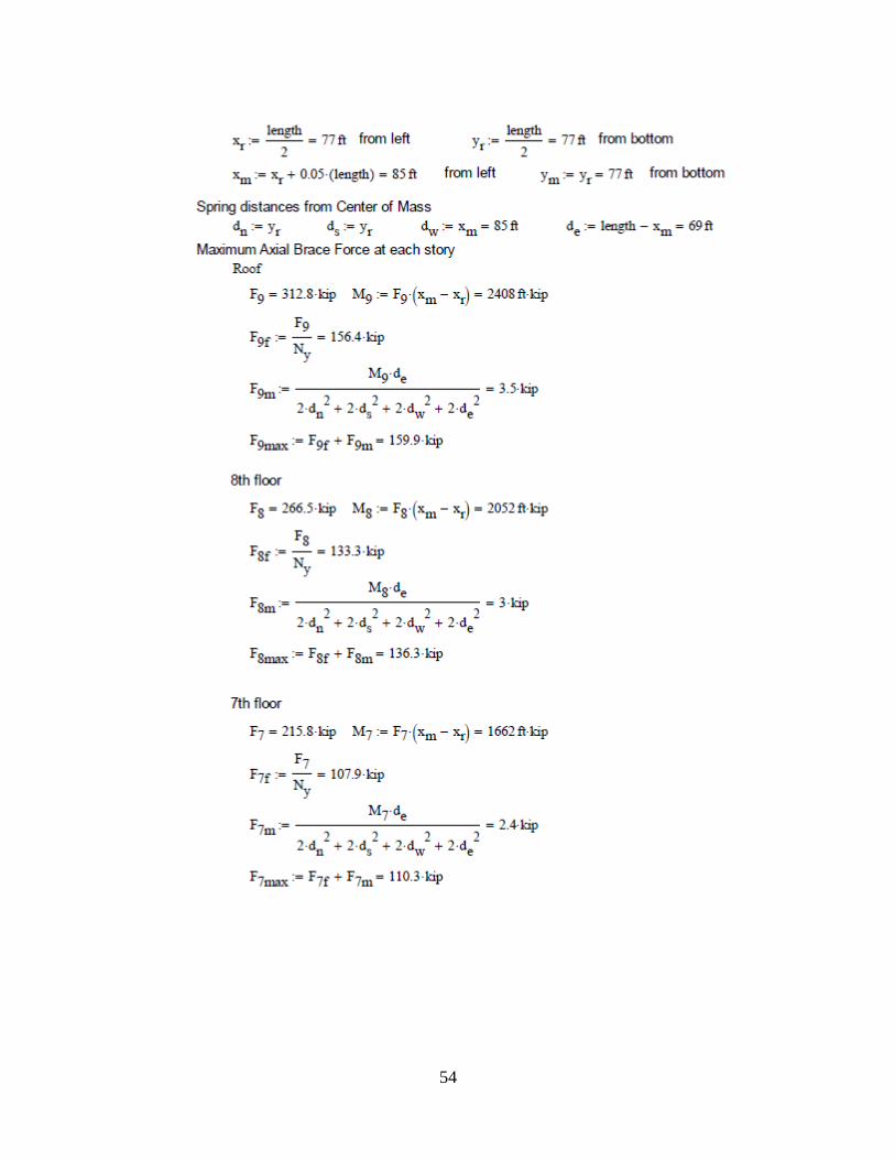
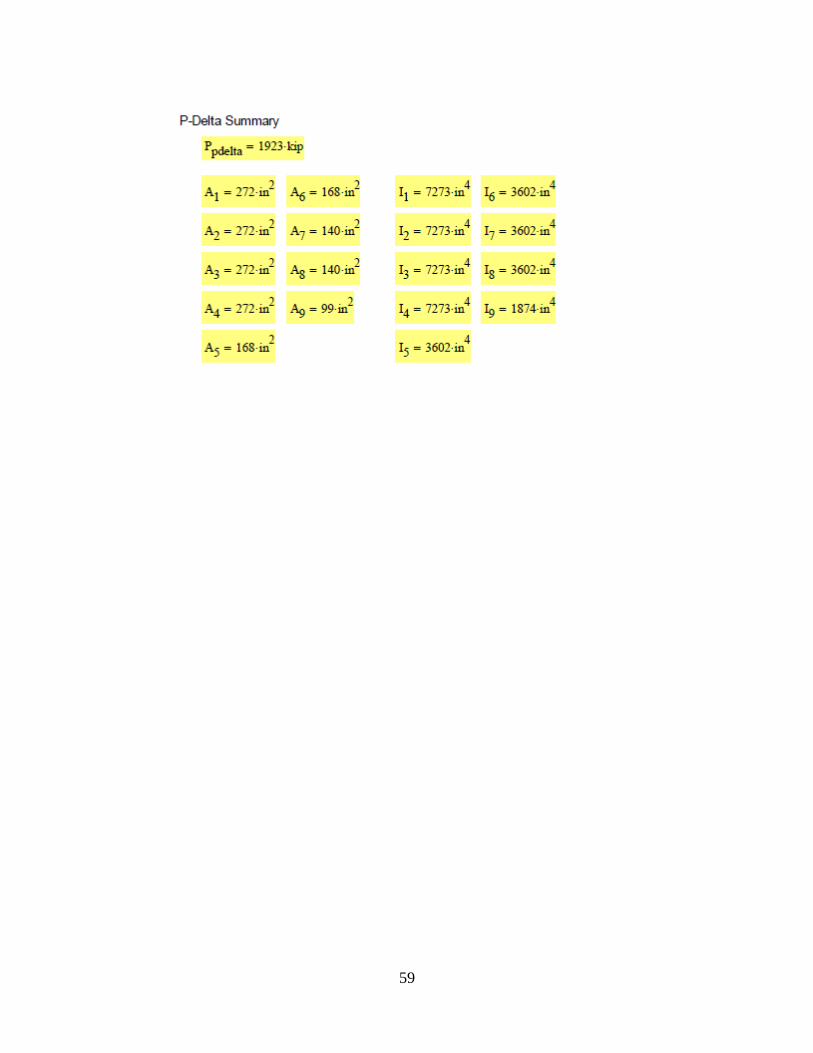
B.2 Building and P-Delta Column Design for 9-Stories