UTM10 in multi-SSID, multi-VLAN network with WMS5316 Version 1.0 UTM10 in multi-SSID, multi-VLAN network with WMS5316 This document describes how to use the UTM10 (unified threat management system) and WMS5316 (wireless management system) to create a multi-VLAN, multi-SSID network in conjunction with a layer 2 or layer 3 switch. Each wired network will have a corresponding wireless network. Wired clients will be able to communicate with wireless clients on the same VLAN. Clients (wired or wireless) will not be able to communicate with clients on other VLANs. For simplicity this example will only use one wireless access point (WNDAP350). Further access points can be added following the configuration laid out here. Also, if a L3 switch is used, this example assumes routing between VLANs is not set up on the switch. Network diagram
Transcript
UTM10 in multi-SSID, multi-VLAN network with WMS5316 Version 1.0
UTM10 in multi-SSID, multi-VLAN network with WMS5316 This document describes how to use the UTM10 (unified threat management system) and WMS5316 (wireless management system) to create a multi-VLAN, multi-SSID network in conjunction with a layer 2 or layer 3 switch. Each wired network will have a corresponding wireless network. Wired clients will be able to communicate with wireless clients on the same VLAN. Clients (wired or wireless) will not be able to communicate with clients on other VLANs. For simplicity this example will only use one wireless access point (WNDAP350). Further access points can be added following the configuration laid out here. Also, if a L3 switch is used, this example assumes routing between VLANs is not set up on the switch.
Network diagram
UTM10 in multi-SSID, multi-VLAN network with WMS5316 Version 1.0
Network setup UTM10 WAN port connected to internet UTM10 port 1 connected to WMS5316 port 1 UTM10 port 2 connected to WNDAP350 LAN port UTM10 port 3 connected to L2/L3 switch port 0/1 UTM10 configuration:
WMS5316 configuration: LAN IP 192.168.1.250 Untagged VLAN: 1 / Management VLAN: 1 Access Point (WNDAP350) configuration: LAN IP 192.168.1.235 Corporate SSID – VLAN 1 Guest SSID – VLAN 2 Note: WNDAP350 is not configured directly. It is configured from the WMS5316. Layer 2 / Layer 3 switch configuration: Management IP 192.168.1.239 Management VLAN = VLAN1 Port configuration: (Untagged = U; Tagged = T) VLAN1 VLAN2 0/1 T T 0/2 U 0/3 U PVID settings: 0/1 = 1; 0/2 = 1; 0/3 = 2
UTM10 in multi-SSID, multi-VLAN network with WMS5316 Version 1.0
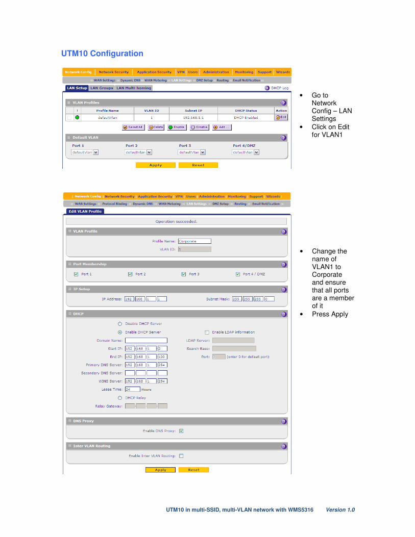
UTM10 Configuration
• Go to Network Config – LAN Settings
• Click on Edit for VLAN1
• Change the name of VLAN1 to Corporate and ensure that all ports are a member of it
• Press Apply
UTM10 in multi-SSID, multi-VLAN network with WMS5316 Version 1.0
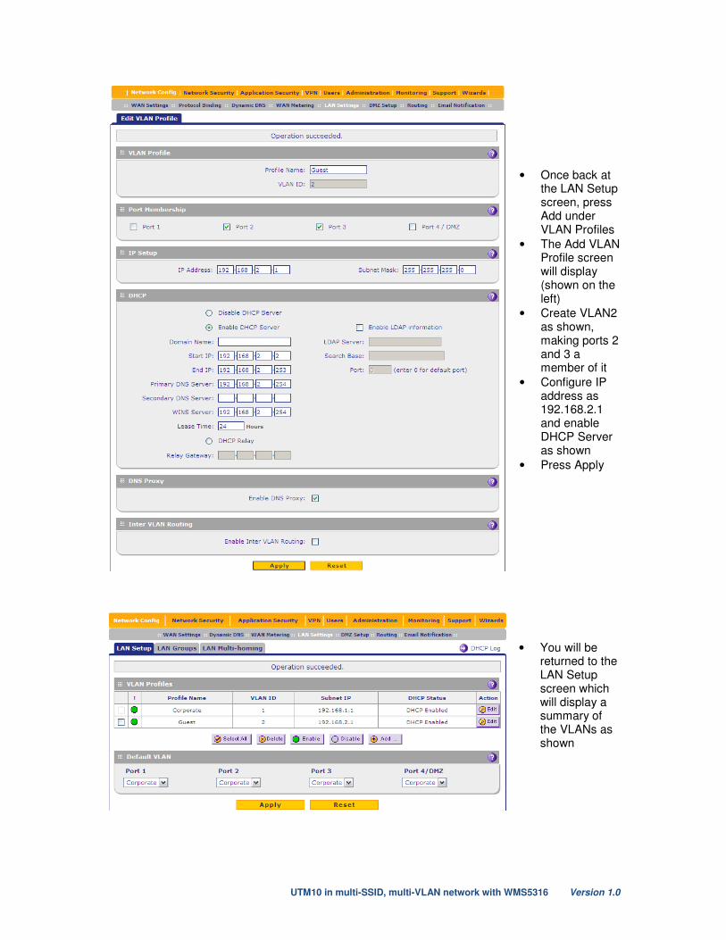
• Once back at the LAN Setup screen, press Add under VLAN Profiles
• The Add VLAN Profile screen will display (shown on the left)
• Create VLAN2 as shown, making ports 2 and 3 a member of it
• Configure IP address as 192.168.2.1 and enable DHCP Server as shown
• Press Apply
• You will be returned to the LAN Setup screen which will display a summary of the VLANs as shown
UTM10 in multi-SSID, multi-VLAN network with WMS5316 Version 1.0
WMS5316 Configuration Note: 1: This document will assume that you have already synchronized one or more access points with the WMS5316. If you are unfamiliar with how to do this, please see chapter 2 of the manual at http://kb.netgear.com/app/answers/detail/a_id/13374 2: We will use Basic Security Profiles which will mean that the SSIDs configured in these profiles will be assigned to all APs. Should you wish to have certain SSIDs assigned to certain APs only, you should use Access Point Groups.
• Under Configuration – System – Basic – VLAN Settings, ensure the settings are as shown
• Go to Configuration – Security – Basic – Profile Settings
• Ensure that both profile 1 and 2 are enabled (enable the tick-box at the far right for each profile)
• Press Apply
• Choose the first profile and press Edit
UTM10 in multi-SSID, multi-VLAN network with WMS5316 Version 1.0
• Configure the profile as shown
• Configure encryption as required also
• Press Apply
• Press Back to return to the Security Profiles List
• Choose the second profile and press Edit
• Again, configure the profile as shown
• Configure encryption as required
• Press Back to return to the Security Profiles List
• The Security Profiles List should now look as shown
UTM10 in multi-SSID, multi-VLAN network with WMS5316 Version 1.0
Testing 1: Connect to the Corporate SSID (VLAN1) and verify the following:
o Client obtains an IP in the range 192.168.1.x o Client can communicate with devices on the wired corporate LAN (VLAN1) o Client cannot communicate with devices on the wired guest LAN (VLAN2) o Client can access the internet
2: Connect to the Guest SSID (VLAN2) and verify the following:
o Client obtains an IP in the range 192.168.2.x o Client can communicate with devices on the wired guest LAN (VLAN2) o Client cannot communicate with devices on the wired corporate LAN (VLAN1) o Client can access the internet
Should you require clients on VLAN1 to be able to communicate with clients on VLAN2, then you can enable Inter-VLAN Routing on both VLANs on the UTM10.