24
>> UTSR >> UTSK >> UTSP >> UTSW FULL OF ENERGY INDUSTRIAL SYSTEMS
1
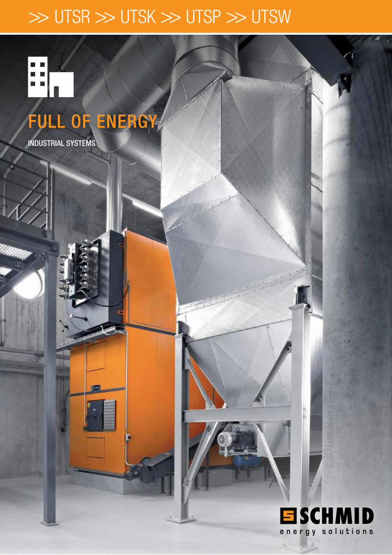
>> UTSR >> UTSK >> UTSP >> UTSW
FULL OF ENERGY INDUSTRIAL SYSTEMS

2
INTELLIGENT POWER GENERATION WITH THE SCHMID CONCEPT
Each chain is as strong as its weakest link – a reality that can also be applied to the function of wood combustion systems. To ensure the effective interaction of all components, we have evolved from a boiler engineering company to a comprehensive system supplier. The individual system components are continuously perfected and optimally coordinated. The result - efficient Schmid systems that meet the ecological and economical demands of modern energy generation systems.
The track-proven Schmid combustion systems set standards in combustion technology and are extremely easy to operate. With advances in technology, the demand for clean combustion is more than satisfied. Due to their outstanding efficiency, Schmid combustion systems are also impressive from an economic viewpoint.
The wide range of different combustion systems covers different operating ranges and requirements.

3
CUTTING EDGE TECHNOLOGY - AN OVERVIEW
UTSR150 - 6'500 KW
UTSK180 - 900 KW
UTSP180 - 900 KW
UTSW300 - 4'200 KW
MOVING GRATE FIRING SYSTEM · woodchips · bark · residual wood · pellets · alternative fuels
UNDERFEED STOKER FIRING SYSTEM · woodchips · residual wood
UNDERFEED STOKER FIRING SYSTEM · pellets
UNDERFEED STOKER FIRING SYSTEM · scrap wood · residual wood · pellets · alternative fuels
PAGE 6
PAGE 8
PAGE 10
PAGE 12
4
5
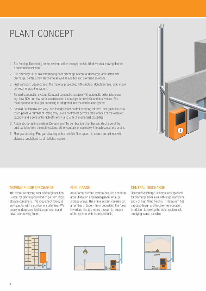
1. Silo feeding: Depending on the system, either through the silo lid, drive-over moving floor or a customised solution.
2. Silo discharge: Fuel silo with moving floor discharge or central discharge, articulated arm discharge, centre screw discharge as well as additional customised solutions.
3. Fuel transport: Depending on the material properties, with single or double screws, drag chain conveyor or pushing system.
4. Schmid combustion system: Compact combustion system with automatic boiler tube clean-ing. Low-NOx and low particle combustion technology for low NOx and dust values. The multi-cyclone for flue gas dedusting is integrated into the combustion system.
5. Schmid PersonalTouch: Very user-friendly boiler control featuring intuitive user guidance on a touch panel. A number of intelligently linked controllers permits maintenance of the required capacity and a constantly high efficiency, also with changing fuel properties.
6. Automatic de-ashing system: De-ashing of the combustion chamber and discharge of the dust particles from the multi-cyclone, either centrally or separately into ash containers or bins.
7. Flue gas cleaning: Flue gas cleaning with a suitable filter system to ensure compliance with statutory regulations for air pollution control.
MOVING FLOOR DISCHARGEThe hydraulic moving floor discharge solution is ideal for discharging wood chips from large storage containers. This robust technology is very popular with a number of customers. We supply underground fuel storage rooms and drive-over moving floors.
CENTRAL DISCHARGE Horizontal discharge is almost unsurpassed for discharge from silos with large diameters and / or high filling heights. This system has a robust design and trouble-free operation. In addition to stoking the boiler system, silo emptying is also possible.
PLANT CONCEPT
FUEL CRANEAn automatic crane system ensures optimum area utilisation and management of large storage areas. The crane system car-ries out a number of tasks - from depositing the fuels in various storage zones through to supply of the system with the mixed fuels.

5
1
2
3
4
6
7
CENTRE SCREW DISCHARGE Centre screw discharge is a simple and track-proven system for small, long rooms for discharging pellets. The angled floor design with conveying screw guarantees quiet and gentle transport of the pellets. The conveying system is low maintenance and has an impressively low power consumption.
ARTICULATED ARM DISCHARGE SYSTEM The articulated arm discharge system permits optimum space utilisation. Discharge with two articulated arms gently transports wood chips or pellets out of small and medium-sized silos or storage rooms. It is suitable for square and round silo configurations.
Fuel logistics play a central role in reliable and economical operation of a combustion system.
A wide range of conveying options is available depending on local space conditions, the fuel properties and the required fuel quantity.
We work with you to find the best transport solution for your requirements. You benefit from our experience from a large number of projects.
FUEL LOGISTICS
6
12
3
4
5
6
14
11
97
10
12
13
8
15
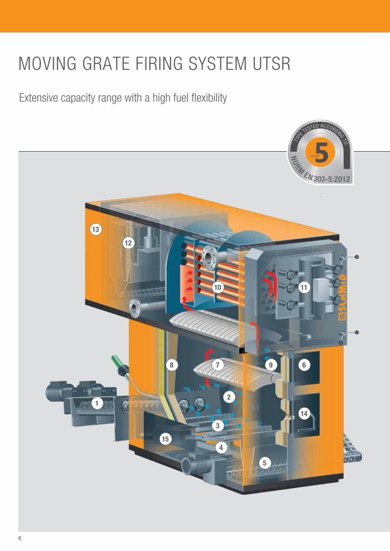
Extensive capacity range with a high fuel flexibility
MOVING GRATE FIRING SYSTEM UTSR
5CLASS
TYPE
TESTED ACCORDING TO
NO
RM EN 303-5:2012

7
1
2 5
3
4
1. Fuel supply with hydraulic feeder, single or double stoker
2. Primary combustion chamber
3. Air-cooled horizontal moving grate
4. Under-grate de-ashing – automatic or manual
5. Automatic grate ash discharge
6. Access to the secondary combustion chamber
7. Radiation vault
8. Refractory concrete for heat storage
9. Secondary combustion chamber – in accordance with low NOx process by means of air control
10. 13-pass steam boiler
11. Boiler door with automatic pulse-jet cleaning system of the boiler tubes
12. Flue gas cleaning by means of multi-cyclone with automatic fly ash discharge
13. Flue gas fan – can be positioned either on the right, left or at the rear
14. Grate door with safety lock
15. Access door to undergrate
AT A GLANCE · Moving grate firing
system
· Operating medium: - Water - Hot water - Steam
· Grate cooling: Air / water
· Grate bar cooling from UTSR-700
· Operating range: 150 - 6'500 kW
· Type-tested according to: EN 303-5:2012 180 - 550 kW
· Capacity control: Modulating
· Fuel moisture content M 10 - 60
· Nominal capacity up to a fuel moisture content of M 55
· Fuel types: - woodchips - bark - residual wood - pellets - alternative fuels
· Standard: - LOW particle system - NOx-reduction
· Optional: - Combustion chamber
camera - Flue gas recirculation - SNCR process
The refractory concrete is secured to the steel structure of the combustion chamber with heat resistant wall anchors. The refractory concrete has a high density as well as a high temperature resistance and is cast in sections. Dilation seams between the sections compensate for expansion of the refractory concrete when the temperature fluctuates. The ceramic fibre mat behind the refractory concrete and the high temperature resistant heat insulation board protect the steel plate structure against overheating.
COMBUSTION CHAMBER DESIGN1. Insulation of the combustion chamber (100 mm)
with external cladding plate
2. Air cooling inside double-wall steel plate construction (5-5, 6-8, 8-10 or 10-10 mm)
3. High temperature resistant heat insulation board (60/75/100 mm)
4. Fireproof ceramic fibre mat coated with aluminium foil (13/25 mm)
5. Fireproof cast concrete (115-150 mm)
8
12
34 5
6
11
9
7
10
12
13
8
14
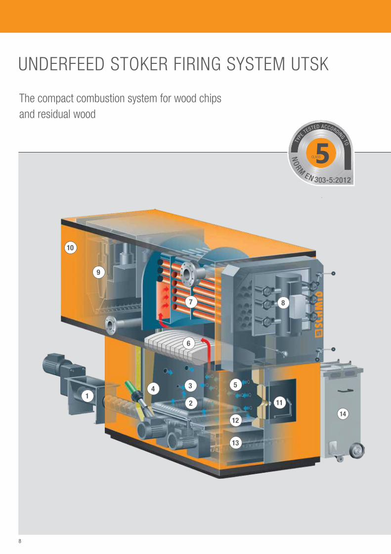
The compact combustion system for wood chips and residual wood
UNDERFEED STOKER FIRING SYSTEM UTSK
5CLASS
TYPE
TESTED ACCORDING TO
NO
RM EN 303-5:2012

9
1
2 5
3
4
1. Fuel supply with stoker screw
2. Combustion tray with cast ribs and primary air supply
3. Combustion chamber
4. Refractory concrete for heat storage
5. Secondary air inlet
6. Radiation vault
7. 3-pass steam boiler
8. Boiler door with automatic pulse-jet cleaning system of the boiler tubes
9. Flue gas cleaning by multi-cyclone with automatic ash particle discharge
10. Flue gas fan – can be positioned either on the right, left or at the rear
11. Grate door with safety lock
12. Burnout grate
13. Automatic grate ash discharge
14. Ash container for grate ash
AT A GLANCE · Underfeed stoker firing
system
· Operating medium: - Water - Hot water - Steam
· Grate cooling: Air
· Operating range: 180 - 900 kW
· Type-tested according to: EN 303-5:2012 180 - 550 kW
· Capacity control: Modulating
· Fuel moisture content M 10 - 50
· Nominal capacity up to a fuel moisture content of M 45
· Fuel types: - woodchips - residual wood
· Standard: - LOW particle system
(controlled air routing)
· Optional: - Flue gas
recirculation
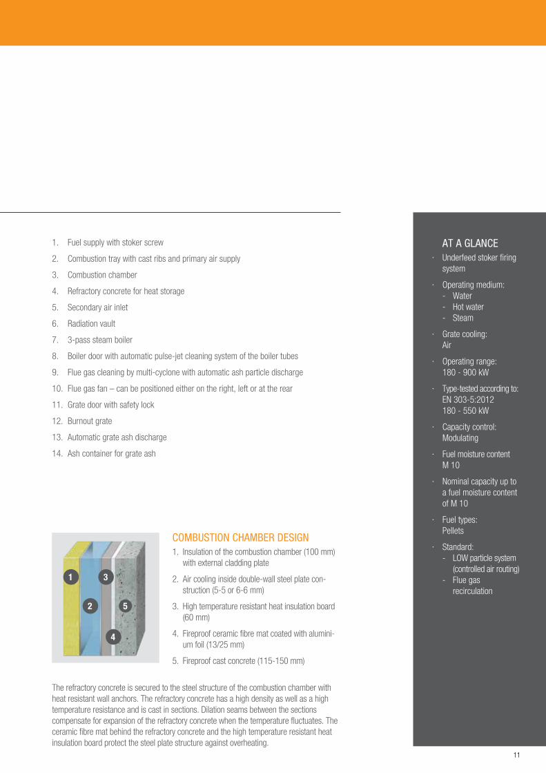
COMBUSTION CHAMBER DESIGN1. Insulation of the combustion chamber (100 mm)
with external cladding plate
2. Air cooling inside double-wall steel plate construction (5-5 or 6-6 mm)
3. High temperature resistant heat insulation board (60 mm)
4. Fireproof ceramic fibre mat coated with aluminium foil (13/25 mm)
5. Fireproof cast concrete (115-150 mm)
The refractory concrete is secured to the steel structure of the combustion chamber with heat resistant wall anchors. The refractory concrete has a high density as well as a high temperature resistance and is cast in sections. Dilation seams between the sections compensate for expansion of the refractory concrete when the temperature fluctuates. The ceramic fibre mat behind the refractory concrete and the high temperature resistant heat insulation board protect the steel plate structure against overheating.

10
12
34 5
6
11
9
7
10
12
13
8
14
The industrial system for pellets
UNDERFEED STOKER FIRING SYSTEM UTSP
5CLASS
TYPE
TESTED ACCORDING TO
NO
RM EN 303-5:2012
11
1
2 5
3
4
AT A GLANCE · Underfeed stoker firing
system
· Operating medium: - Water - Hot water - Steam
· Grate cooling: Air
· Operating range: 180 - 900 kW
· Type-tested according to: EN 303-5:2012 180 - 550 kW
· Capacity control: Modulating
· Fuel moisture content M 10
· Nominal capacity up to a fuel moisture content of M 10
· Fuel types: Pellets
· Standard: - LOW particle system
(controlled air routing) - Flue gas
recirculation
COMBUSTION CHAMBER DESIGN1. Insulation of the combustion chamber (100 mm)
with external cladding plate
2. Air cooling inside double-wall steel plate con-struction (5-5 or 6-6 mm)
3. High temperature resistant heat insulation board (60 mm)
4. Fireproof ceramic fibre mat coated with alumini-um foil (13/25 mm)
5. Fireproof cast concrete (115-150 mm)
The refractory concrete is secured to the steel structure of the combustion chamber with heat resistant wall anchors. The refractory concrete has a high density as well as a high temperature resistance and is cast in sections. Dilation seams between the sections compensate for expansion of the refractory concrete when the temperature fluctuates. The ceramic fibre mat behind the refractory concrete and the high temperature resistant heat insulation board protect the steel plate structure against overheating.
1. Fuel supply with stoker screw
2. Combustion tray with cast ribs and primary air supply
3. Combustion chamber
4. Refractory concrete for heat storage
5. Secondary air inlet
6. Radiation vault
7. 3-pass steam boiler
8. Boiler door with automatic pulse-jet cleaning system of the boiler tubes
9. Flue gas cleaning by multi-cyclone with automatic ash particle discharge
10. Flue gas fan – can be positioned either on the right, left or at the rear
11. Grate door with safety lock
12. Burnout grate
13. Automatic grate ash discharge
14. Ash container for grate ash
12
1
23
4
5
6
14
15
11
9
7
10
12
13
8
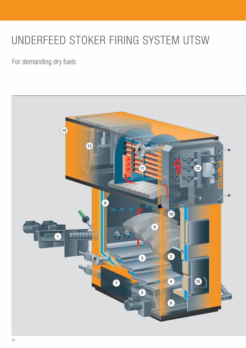
For demanding dry fuels
UNDERFEED STOKER FIRING SYSTEM UTSW

13
1
2 5
3
4
1. Fuel supply with stoker screw
2. Combustion chamber with water cooling
3. Water-cooled step grate
4. Burnout zone
5. Under-grate de-ashing – automatic or manual
6. Automatic grate ash discharge
7. Access door to under-grate
8. Radiation vault
9. Refractory concrete with defined heat passage
10. Secondary combustion chamber – in accordance with low NOx process by means of air stages
11. 3-pass steam boiler
12. Boiler door with automatic pulse-jet cleaning system of the boiler tubes
13. Flue gas cleaning by multi-cyclone with automatic fly ash discharge
14. Flue gas fan – can be positioned either on the right, left or at the rear
15. Grate door with safety lock
AT A GLANCE · Underfeed stoker firing
system
· Operating medium: - Water - Hot water - Steam
· Combustion chamber & grate cooling: Water
· Operating range: 300 - 4‘200 kW
· Capacity control: Modulating
· Fuel moisture content M 8 - 44
· Nominal capacity up to a fuel moisture content of M 35
· Fuel types: - scrap wood - residual wood - pellets - alternative fuels
· Standard: - LOW particle system
(controlled air routing) - NOx-reduction (in
accordance with the stepped combustion principle)
· Optional: - Combustion chamber
camera - Flue gas recirculation - SNCR process
(Nitrogen oxide reduction)
COMBUSTION CHAMBER DESIGN1. Insulation of the combustion chamber (100 mm)
with external cladding plate
2. Water cooling inside double-walled steel plate structure connected with tension bolts
3. Fireproof ceramic fibre mat coated with alumin-ium foil
4. Heat resistant wall anchors
5. Fireproof cast concrete (100 mm)
The refractory concrete is secured to the steel structure of the combustion chamber with heat resistant wall anchors. The refractory concrete has a high density as well as a high temperature resistance and is cast in sections. Dilation seams between the sections compensate for expansion of the refractory concrete when the temperature fluctuates. The ceramic fibre mat behind the refractory concrete protects the steel plate structure against overheating.

14
TRACK-PROVEN COMPONENTS FOR TAILORED SYSTEM SOLUTIONS
AUTOMATIC UNDER-GRATE DE-ASHINGAutomatic discharge of the ash below the moving grate with the moving floor system directly into the grate de-ashing screw or into a gravity chute.
AUTOMATIC DE-ASHINGCentral or separate automatic de-ashing of grate and cyclone ash. With the central version, the ash is discharged mechanically from the combustion grate and the multi-cyclone into a joint ash container on wheels. With the separate version, the ash is discharged from the combustion grate and the multi-cyclone into individual containers.
PNEUMATIC CLEANING SYSTEMClean boiler tubes are essential for the service life and efficiency of a system. All boiler tubes are cleaned with periodic compressed air pulses during operation.
IGNITIONUp to 900 kW nominal capacity and up to a maximum fuel moisture content of M 35, electrical industrial hot air blowers are available for igniting the fuel in the combustion tray or on the moving grate. From a nominal capacity of 900 kW and up to a maximum fuel moisture content of M 55, ignition burners run with propane gas can be used for the UTSR and UTSW combustion systems.
15
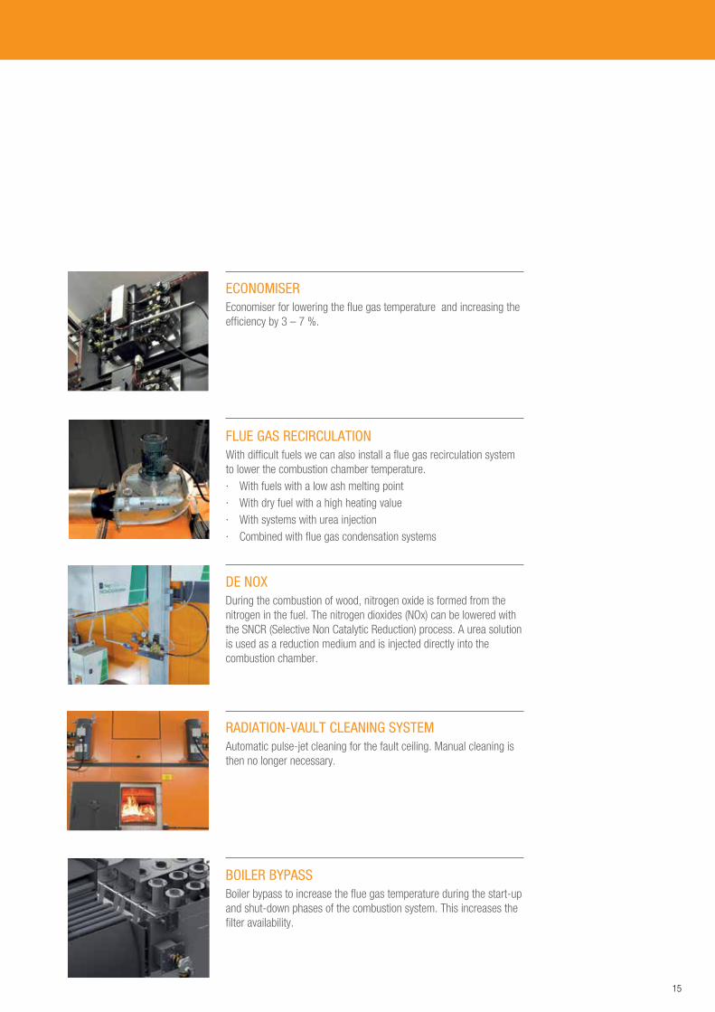
DE NOXDuring the combustion of wood, nitrogen oxide is formed from the nitrogen in the fuel. The nitrogen dioxides (NOx) can be lowered with the SNCR (Selective Non Catalytic Reduction) process. A urea solution is used as a reduction medium and is injected directly into the combustion chamber.
RADIATION-VAULT CLEANING SYSTEMAutomatic pulse-jet cleaning for the fault ceiling. Manual cleaning is then no longer necessary.
ECONOMISEREconomiser for lowering the flue gas temperature and increasing the efficiency by 3 – 7 %.
BOILER BYPASSBoiler bypass to increase the flue gas temperature during the start-up and shut-down phases of the combustion system. This increases the filter availability.
FLUE GAS RECIRCULATIONWith difficult fuels we can also install a flue gas recirculation system to lower the combustion chamber temperature. · With fuels with a low ash melting point · With dry fuel with a high heating value · With systems with urea injection · Combined with flue gas condensation systems

16
THE CONTROL UNIT – THE HEART OF EVERY SCHMID SYSTEM

17
The Schmid PersonalTouch boiler control has been in successful operation for many years in hundreds of plants. The wide range of adjustment options is unique. Operation is carried out conveniently from the touch screen.
The third generation of the PersonalTouch control unit is a Schmid development. The company know-how guarantees continuous improvements. Update options are available.
DESIGN AND USABILITYThe most obvious change in the third generation of the PersonalTouch boiler control unit is the new user interface. It employs the very latest technology. Great attention was paid to intuitive operation during its design. The Schmid boiler control unit should not only be extremely functional and look good, but should also be easy to use.
TRACK-PROVEN CONTROLIt is to be expected that a combustion system generates heat and features controls for capacity, combustion temperature, underpressure, residual oxygen and air flow. It becomes really interesting when complex control tasks are required for heating groups as well as steam and hot water systems. In this field Schmid AG has many decades of experience at its disposal.
STABLE AIR FLOWS FOR ALL FUEL TYPESAn outstanding feature of the Schmid control units is that the air flows supplied to the combustion system are measured and controlled. The PersonalTouch control unit therefore ensures that the exact air flow is supplied to the combustion system irrespective of the operating mode, grate occupancy or the fuel density.
THE LATEST O2 CONTROLFor optimum control of the residual oxygen volume, either the air flow or the fuel quantity can be automatically varied. The PersonalTouch control unit supports both control methods and even permits a combination of both. The optimum control can therefore be defined for each application.
BOILER CONTROL ADAPTED TO THE ENERGY REQUIREMENTSThe aim of the control of the buffer boiler is to ensure that suffi-cient energy is available at all times and that the wood combustion system requires as few starts as possible. The PersonalTouch control unit offers an optimised solution. Depending
on requirements, the following operating modes can be selected: Control to ensure a constant accumulator level, control to a set accumulator charge value by a higher-level control, diagram-based operation depending on the outside temperature and accumulator charge level as well as control on a weather-sensitive basis.
For further optimisation foreseeable demand peaks or low-load phases can be proactively managed by increasing or lowering the set accumulator level. The respective times can be set on weekly timers.
AUTOMATIC FUEL DETECTIONThe moisture of the supplied fuel influences optimum combustion to a degree which should not be underestimated. This moisture can be measured directly and indirectly and therefore automatically modify the setup of the boiler control.
BIGDATA MEANS ADDED BENEFITSEach measured value is recorded in the PersonalTouch control unit for an entire year. This generates an unimaginable volume of data. But who should ever look at and evaluate this data? This is where the automatic remote maintenance option comes into play and analyses the BigData fully automatically.

18
0 5 10 15 20 25 30 35 40 45 50 55 60 65 M
KW
7000
6000
5000
4000
3000
2000
1000
800
600
400
200
0
UTSK UTSW
UTSR UTSP
SCHMID BOILERS - AN OVERVIEW
Figure 1: Application range of the combustion systems depending on the fuel moisture content and nominal capacity
FROM THE RAW MATERIAL TO ENERGY!
Profit from our many years of experience in planning and installation of wood combustion systems. We would be pleased to offer you a solution that is fully tailored to your requirements.
SELECTION OF THE BOILER CAPACITY:Correct dimensioning is decisive for efficient and low-maintenance operation of the combustion system. During planning, continuous operation should be aimed for. Single boiler systems with summer operation should have a sufficiently long minimum service life. Other-wise we recommend planning multiple boiler systems, also taking the minimum service life into account.
ACCUMULATOR:The energy accumulator covers peak loads, has a positive effect on the control behaviour of the combustion system and makes it possible to achieve the minimum service life and ensure filter availability. As a rule of thumb we recommend an installed capacity of 30 litres per kW for the largest boiler.
FUEL:Changes in the fuel moisture level, the heating value and the composition during ongoing operation of the combustion system influences the combustion settings. To ensure optimum combustion at any time, three manual or automatically programmable memory settings are available for selection of the settings that are most suitable for the fuel. During summer operation we recommend use of fuel with a fuel moisture content of ≤ M35 to optimise the minimum service life of the combustion system.
FUEL SUPPLY:The fuel supply is finely dosed and continuously adapted to the currently required boiler capacity during both screw transport and pusher systems. As a result, the required capacity is generated at all load levels.
AUTOMATIC IGNITION UNIT:With the use of an ignition combustion unit, automatic sequential control is possible with multiple boiler systems. Operation with firebed maintenance is therefore no longer necessary.

19
FLUE GAS RECIRCULATION:When combined with flue gas condensation systems, with fuel with a low ash melting point or a low fuel moisture content, we recommend the use of flue gas recirculation. This guarantees a high level of efficiency with gentle operation and prevents the formation of slag.
FLUE GAS CLEANING:To achieve a high filter efficiency, the minimum heat reduction in low-load operation must be observed. Planning of an energy accumulator is decisive for optimum operation of dry filter systems in addition to the correct dimensions of the combustion system.
CONTROL SYSTEM:To benefit completely from the power of the Industrial Systems product range, we recommend the integration of the
· Boiler pump incl. the return temperature control group for return temperature increase and constant regulation of the flow temperature into the technical control design.
· Automatic ignition · Cascade circuit · Accumulator management
in the PersonalTouch boiler control unit.
This ensures maximum efficiency, availability, and continuous compli-ance with the required emissions.
REMOTE ACCESS:Remote access via PC, tablet or smartphone enables you to conveniently control your system from any location. Profit from the optional combustion chamber camera for visual monitoring of the combustion chamber. The remote access solution also permits access to the full range of Schmid After Sales services.
HEAT GENERATION WITH ACCUMULATOR:Load peaks are covered by the accumulator. As a result the combustion systems can be designed with a lower capacity and the number of activation and deactivation operations of the combustion system is lowered. The longer service life that is achieved as a result guarantees filter availability. Systems with summer operation or extension reserves are preferably designed as multiple boiler systems.
MONOVALENT SYSTEM:Wood combustion system 1 for the base load, wood combustion system 2 for peak and low load operation (summer time).
Dimensioning examples: · 80 - 90 % of the annual heat requirements from wood energy,
distributed as 2/3 of the annual heat requirements to boiler 1 and 1/3 of the annual heat requirements to boiler 2.
· The load peaks are covered by the accumulator.
BIVALENT SYSTEM (FIG. 2): Wood combustion system 1 for the base load, wood combustion sys-tem 2 for peak and low load operation (summer time). Oil/gas boiler as extension reserve or for redundancy.
Dimensioning examples: · 80 - 90 % of the annual heat requirements from wood energy,
distributed as 2/3 of the annual heat requirements to boiler 1 and 1/3 of the annual heat requirements to boiler 2.
· The load peaks are covered by the accumulator. · Oil/gas boiler as extension reserve for redundancy
Figure 2: Diagram of a bivalent system with accumulator
Wood boiler
Wood boiler
OIL / GAS BOILER
Accumulator

20
SYSTEM OPERATOR
SystemCUSTOMER ACCESS
LOCAL ACCESS VIA LAN
HARDWARE VPN-CLIENT
WEB ACCESS
SERVER
SERVICE SCHMID ACCESS
21
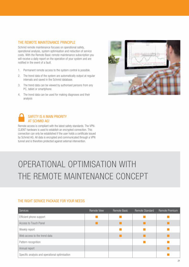
THE REMOTE MAINTENANCE PRINCIPLESchmid remote maintenance focuses on operational safety, operational analysis, system optimisation and reduction of service costs. With the Remote Basic remote maintenance subscription you will receive a daily report on the operation of your system and are notified in the event of a fault.
1. Permanent remote access to the system control is possible.
2. The trend data of the system are automatically output at regular intervals and saved in the Schmid database.
3. The trend data can be viewed by authorised persons from any PC, tablet or smartphone.
4. The trend data can be used for making diagnoses and their analysis
SAFETY IS A MAIN PRIORITY AT SCHMID AG!
Remote access is compliant with the latest safety standards. The VPN-CLIENT hardware is used to establish an encrypted connection. This connection can only be established if the user holds a certificate issued by Schmid AG. All data is encrypted and communicated through a VPN tunnel and is therefore protected against external intervention.
OPERATIONAL OPTIMISATION WITH THE REMOTE MAINTENANCE CONCEPT
THE RIGHT SERVICE PACKAGE FOR YOUR NEEDS
Services Remote View Remote Basic Remote Standard Remote Premium
Efficient phone support
Access to Touch Panel
Weekly report
Web access to the trend data
Pattern recognition
Annual report
Specific analysis and operational optimisation

22
COMPREHENSIVE SERVICES – TO SAFEGUARD YOUR INVESTMENT

23
We plan and supply not only solutions that are geared to individual requirements, but also support you with a global first class 24-hour, 365 day service.
SCHMID PERSONNEL · Competent all-rounders · Reliable · Conscientious · Customer-oriented · Solution-oriented
SERVICE · 24-hour hotline / stand-by · Repair and trouble-shooting · Remote maintenance and technical support · System maintenance and servicing · Retrofitting and operational optimisation · Third-party system maintenance
SERVICE AGREEMENTS · Preventative and emission maintenance,
either annually or upon appointment · Monitoring of official measurement · Remote maintenance to boost efficiency · System maintenance and operation
SPARE PARTS · Global spare parts service · Requirement-based emergency packages · Fast availability
TRAINING · System maintenance and control unit basics · Control behaviour and combustion temperature · Operational optimisation · Operation of steam and thermal oil systems · Professional training
INDUSTRYAGRICULTURE TRADE

03.1
7/E
- Sub
ject
to c
hang
e w
ithou
t not
ice.
SCHMID AG, ENERGY SOLUTIONS
Hörnlistrasse 12CH-8360 Eschlikon
Telephone +41 (0)71 973 73 73Telefax +41 (0)71 973 73 70
SCHMID AG, ENERGY SOLUTIONS
Industriestrasse 17 · CH-4713 Matzendorf · Telephone +41 (0)62 389 20 50 · Telefax +41 (0)62 389 20 51
SCHMID SA, ENERGY SOLUTIONS
Rue St. Michel 10 · CH-1510 Moudon · Telephone +41 (0)21 905 95 05 · Telefax +41 (0)21 905 95 06 · [email protected]
SCHMID GMBH & CO. KG, ENERGY SOLUTIONS
Kettemerstrasse 25 · D-70794 Filderstadt · Telephone +49 (0)711 70 956-0 · Telefax +49 (0)711 70 956-10 · [email protected]
SCHMID ENERGY SOLUTIONS GMBH
Hans-Thalhammer-Strasse 4 · AT-8501 Lieboch · Telephone +34 (0)3136 61580 · [email protected]
SCHMID ITALIA S.R.L.
C.so Repubblica, 5 · I-10090 San Giorgio Canavese · Telephone +39 (0)124 32 167 · Telefax +39 (0)124 51 85 · [email protected]
SCHMID FRANCE ENERGY SOLUTIONS
Quartier des Entrepreneurs · Aire de la Thur · Route de Guebwiller · F-68840 Pulversheim · Telephone +33 (0)3 89 28 50 82 · Telefax +33 (0)3 89 48 04 90 · [email protected]
SCHMID POLSKA SP. Z.O.O.
Ul. Niska 6 · 82-300 Elblag · Polen


