V T T T I E D O T T E I T A 2129 Tommi Aihkisalo Remote maintenance and development of home automation applications VTT RESEARCH NOTES TECHNICAL RESEARCH CENTRE OF FINLAND ESPOO 2002 lookup service service proxy server calculation service printing service coffee maker service service proxy 1. discover the lookup service and upload service proxies 2. discover the lookup service and download needed proxies 3. use the service via its proxy client client application service proxy coffee maker interface
Transcript
V T
T
T I
E D
O T
T E
I T
A2 1 2 9
Tommi Aihkisalo
Remote maintenance anddevelopment of home automationapplications
V T T R E S E A R C H N O T E S
TECHNICAL RESEARCH CENTRE OF FINLAND ESPOO 2002
lookup service
serviceproxyservice
proxyserviceproxy
servercalculation service
serviceproxy
printing service
serviceproxy
coffee makerservice
serviceproxy
1. discover the lookup serviceand upload service proxies
2. discover the lookup serviceand download needed proxies
3. use the service via its proxy
client
client application
serviceproxy
coffeemaker
interface
VTT TIEDOTTEITA � MEDDELANDEN � RESEARCH NOTES 2129
Aihkisalo, Tommi. Remote maintenance and development of home automation applications. Espoo 2002.Technical Research Centre of Finland, VTT Tiedotteita � Meddelanden � Research Notes 2129. 85 p.
Keywords Jini, XML, LON, Local Operating Network, residential gateways, remote maintenance,remote development
AbstractThis work studies methods and technologies for remote maintenance and developmentof home automation applications. A major problem in remote home automationconfiguration seems to be the missing information concerning the properties andattributes of the home�s automation hardware. This study defines methods and aprototype to describe the automation hardware remotely for developer along withfurther methods to use to deliver these descriptions to the developer.
A review is done of the traditional automation technologies and automation networking.Local Operating Network automation technology and networking methods are studiedmore deeply, while the prototype presented in this work used this technology. Theaspects of modern home automation are reviewed and studied. This includes crucialtechnologies for this work like residential gateways.
A few description technologies for describing automation platform are examined. Theseinclude XML, databases and JavaBeans. On the basis of evaluation XML is chosen dueto its compactness and simplicity. Furthermore distributed computing technologies arepresented which include the Jini concept. This distribution technology is utilised incommunication between homes and application developer.
The required XML structures are defined for device description purposes and otherprototype software for residential gateway and developer�s client are defined. Theresidential gateway software is described with UML and the software was implementedusing the Java programming language due to its good networking abilities. On the basisof this work it was seen that is possible to describe the home�s automation platform anddeliver the descriptions for use of the remote developer.
Especially XML was seen as very suitable for this purpose and the Jini distributionconcept was also seen suitable for delivering this and other maintenance anddevelopment services to the remote developer.
4
PrefaceThe basis of this thesis was laid by the project done as a student project of theUniversity of Oulu in co-operation with VTT Electronics. In that project, a basicconcept and a prototype for remote control and remote configuration was presented.This thesis presented a continuation to that project. Problems were studied and solutionspresented for remote maintenance and the develpment of home automation applications.This work was guided and assisted by the supervising professor Jouko Paaso and thesecond supervising professor Tino Pyssysalo from the University of Oulu. I want tothank them and all my collagues for their efforts of helping me.
This work was offered to me and made possible by the supervisor Hannu Rytilä, m.A.,from VTT Electronics. I want to express my gratitude to both him and the secondsupervisor Eila Niemelä, Ph.D., from VTT Electronics.
Further I want to thank Dave Bradburn for straightening my mistakes and errors inEnglish language.
List of symbols ..................................................................................................................7
1. Introduction..................................................................................................................91.1 Background.........................................................................................................91.2 Research problem and methods........................................................................101.3 Boundaries of this research ..............................................................................11
2. Classifications and general concepts in the field of automation................................122.1 Automation devices ..........................................................................................122.2 Automation networks .......................................................................................142.3 Local Operating Network .................................................................................17
2.3.1 Addressing in LON networks...............................................................182.3.2 LonTalk protocol layers .......................................................................202.3.3 Network variables ................................................................................212.3.4 Functional profiles ...............................................................................232.3.5 Self-documentation and -identification................................................24
3. Modern home automation ..........................................................................................263.1 Residential area networks and local area networks..........................................273.2 Residential gateways ........................................................................................303.3 Current residential gateway standards..............................................................323.4 Conclusions of this chapter ..............................................................................33
4. Technologies for presenting device descriptions.......................................................354.1 XML-presentation ............................................................................................35
4.1.1 Structure of the XML document ..........................................................354.1.2 Structure of the elements......................................................................36
4.2 Software component technology ......................................................................374.2.1 JavaBeans components.........................................................................374.2.2 JavaBeans as a collection of information.............................................38
4.3 Databases..........................................................................................................384.4 Evaluation of description technologies ............................................................40
5. Distribution technologies ...........................................................................................425.1 Open Distributed Processing reference model .................................................425.2 Engineering viewpoint......................................................................................43
6. Requirements set by the previous work .....................................................................506.1 Specified system concept .................................................................................506.2 Basic structure of the prototype system developed in this study......................526.3 Requirements of the prototype system .............................................................54
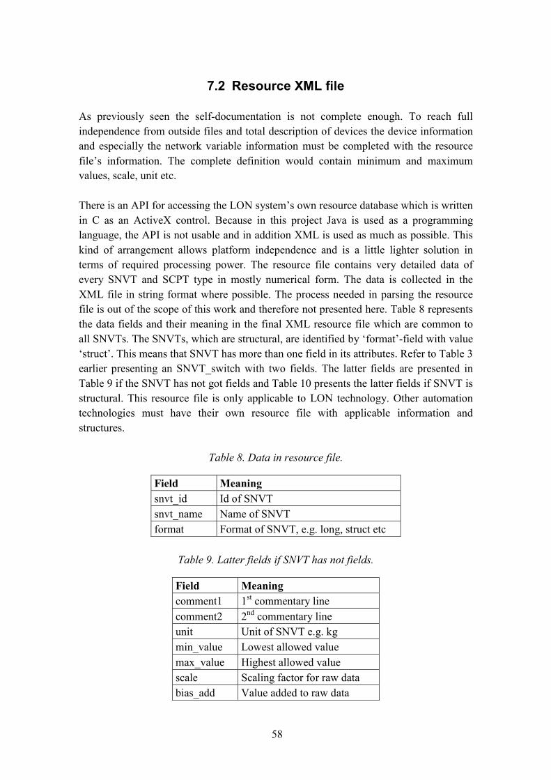
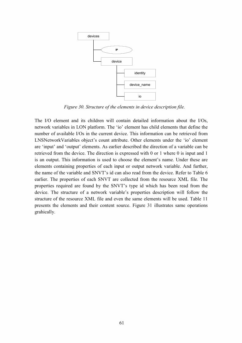
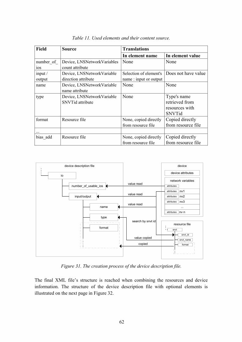
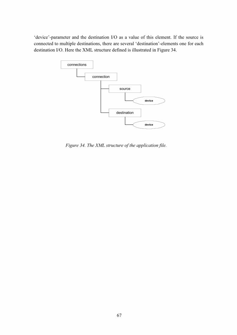
7. XML description of devices.......................................................................................567.1 Data available as self-documentation and -identification from API ................567.2 Resource XML file ...........................................................................................587.3 Structure of the device description XML file...................................................607.4 Use of XSLT in forming the device description file ........................................647.5 Application description file ..............................................................................66
8. Definition of the prototype.........................................................................................688.1 System architecture ..........................................................................................698.2 Collaborations in system ..................................................................................718.3 Implementation.................................................................................................778.4 Use of the XML device descriptions ................................................................78
ISO International Organisation for Standardisation
ISP Internet Service Provider
Kbps Kilo bits per second
LAN Local Area Network
LNS LON Network Services
LON Local Operating Network
MAP Manufacturing Automation Protocol
Mbps Mega bits per second
8
ORB Object Request Broker
OSGi Open Service Gateway initiative
OSI Open Systems Interconnection
PC Personal Computer
PID Proportional Integral Differential
PLC Programmable Logic Controller
POTS Plain Ordinary Telephone Service
RAM Random Access Memory
RAN Residential Area Network
RMI Remote Method Invocation
RM-ODP Reference Model � Open Distributed Processing
ROM Read Only Memory
SCPT Standard Configuration Property Type
SNVT Standard Network Variable Type
SWAP Shared Wireless Access Protocol
TCP/IP Transmission Control Protocol/Internet Protocol
UML Unified Modelling Language
UPnP Universal Plug and Play
UPS Uninterruptiple Power System
WAN World Area Network
WAP Wireless Application Protocol
VCR Video Casette Recorder
WML Wireless Markup Language
XIF eXternal Interface File
XML eXtended Markup Language
XSL eXteneded Stylesheet Language
XSLT eXteneded Stylesheet Language for Transformations
9
1. Introduction1.1 Background
Bringing automation into the home environment is not a new idea. Automation hasstarted with simple mechanically controlled automatic washing machines and timer-controlled ovens. The modern processor-controlled devices have invaded homeseverywhere in the world. All the time the main idea has been to make everyday livingeasier and more comfortable for inhabitants of the homes. Modern home automationgenerally means a process or a system enhancing everyone�s life, safety, and efficiencywith intelligently controlled home appliances [1].
The newest boom in the market is networking devices together in homes and taking thecontrols outside the home. Today there are systems available with which one can turnthe sauna on, even when not at home. This can be done with personal communicationdevices like mobile phones, which are connected to services for controlling the home. Inthe future, mobile Internet services will make it possible to do this from almostanywhere at any time. Another trend is to design intelligent devices which communicatewith each other. Home appliances can notify other devices of their actions and states.For example, a home security unit would broadcast a message to all lights signallingthat nobody is at home at the moment. Consequently, the lights can take the appropriateaction like turning themselves off. But it seems that nobody has yet paid too muchattention to the most essential problem of intelligent home environments: who is goingto develop these customised applications for home environments?
Everyone who has ever tried to program modern VCRs knows how complicated the useof modern devices sometimes is. Everyone would simply like to buy a new device andplug its power cable into the wall outlet and start using it. So there is a gap for a serviceprovider to provide services for the homeowner to control home appliances remotely,and to configure devices and applications for the home. From now on, the remotedeveloper and service provider are understood to be one in the same, while the serviceprovider in this work provides developing and maintenance services. When solutionslike this become more common, it is not profitable for the service providers to visitevery home to connect and configure devices every time the new ones are bought. Thisrises the problem of absent information from the automation devices in home. Thisstudy tries to find ways and solutions to solve this problem. Only a few devicemanufacturers offer some solutions. But those solutions have been usually tied to themanufacturers� own hardware technology and are not interconnectable with othertechnologies.
10
This work examines methods and technologies for remote maintenance anddevelopment of home automation applications, because services like this will be morecommon in future. A concept and a prototype are presented to answer these problems.The prototype contains server software for homes and some tools for those who providedeveloping services to maintain and develop remotely applications for automationplatforms. The concept contains a method to describe the automation platform to solveproblems of distance between the developer and actual platform.
1.2 Research problem and methods
The main problem in this study is how the service provider can remotely develop andmaintain applications used to the control home automation especially without priorinformation about the physical devices located in homes. Considering this, the researchproblem can be stated as a chain of questions. A question leads to another until we reacha bottom level with very fundamental questions. Answers to more generic questions canbe derived afterwards based on earlier answers. The main questions that arise from thistheme are:
How is the automation platform configured remotely?
Where is this configuration task done?
How are the newly added devices noticed and the service provider informed?
How does the service provider get information and properties of the new and existingdevices?
How are the properties and other data of different kinds of devices described?
Is it possible to create a universal and generic description of devices?
This study aims to answer these questions by constructing the most essential parts of thesystem needed in the remote applications development and maintenance. A prototypewill be developed and constructed to achieve this. The research method in this studywill be a constructive method. The aim is already known but methods to achieve the aimare not known [2]. This work starts with a review of theories applicable to generalautomation concepts and classifications, further distribution technologies, residentialgateway solutions and description methods applicable for device description. The basicframework set by the previous project is described, and it will be used in this study too.
11
The work continues with the definition of the necessary functions and construction ofthe prototype utilising technologies presented in the theory part.
1.3 Boundaries of this research
It has been decided earlier by the subscriber of this work to use LonWorks baseddevices as the automation platform. Up to this point it has been seen that this technologyprovides properties which are useful to this study. One of those properties is a self-documentation ability. This means that devices store some basic information aboutthemselves, which is accessible to the development tools. Standard PCs will be used asan implementation platform because they are commonly available and softwaredevelopment is relatively easier for them than for dedicated embedded systems.
The programming technologies used in this study will be Java-based due to its usabilityover multiple platforms and its good support for distribution and telecommunications. Afew distribution concepts will be considered in this work but due to the choice of theJava platform, Jini is seen as the strongest candidate as a distribution technology. Theother distribution technologies are reviewed for comparison purposes.
A generic description method and its conventions are going to be developed for thedescription of devices. Several technologies for presenting devices are considered. Themost promising one is the XML mark-up language. The other ones under considerationinclude conventional databases and software component technologies. Later on in thiswork, all these applicable technologies will be rated and the one that seems the best willbe chosen.
It seems that the prototype system will contain a home server along with suitablesoftware to handle the required tasks. The most essential task of a home server is theability to probe the automation platform and on the basis of that to create the devicedescriptions. Generally speaking automation devices must have self-explanatoryinformation available, which is also retrievable by the server. Further, the server has tosupply device descriptions to the clients needing them and furthermore to allow remotedevelopment of automation applications. Therefore home server software must havefacilities to control the selected LonWorks automation platform and handle distributionof its maintenance services using the selected distribution concept. This also means thatclient software must have the capability to use the service through this same distributionpractice. The server and clients must utilise networking to allow distributed computingbetween them. The prototype�s client part must be able to handle device descriptionsand on the basis of them to create home automation applications using distributedservices of the home server.
12
2. Classifications and general concepts in thefield of automation
This chapter reviews the general automation concepts and practices that are alsoapplicable to home automation. The terms and concepts presented here will be usedlater on in this work. As mentioned in the beginning, this work is implemented usingLonWorks compatible devices. Furthermore this chapter reviews the technology used inLonWorks compatible devices. A view is created of the structure of devices andnetworking conventions. Furthermore the important features of self-documentation andthe application definition process are described. From now on the LonWorks devicesand networks are referred to as LON.
2.1 Automation devices
Automation devices can be divided roughly into three categories: sensors, actuators, andcontrolling devices. The sensors measure the state of an automated process or object. Arefrigerator is taken here as a simple example. The actuators make changes in theobject�s state, e.g. the compressor cools the refrigerator. A controlling device makesdecisions based on information measured by sensors. The example discussed here, arefrigerator, contains a refrigeration process the state of which is measured by athermostat and the decisions for a proper state change is made by the thermostat.Therefore the thermostat is actually both sensor and controlling device which makesdecisions. Figure 1 [3] presents the automated process with actuators, sensors, and thecontrolling system. [3]
Automated process
SensorsActuators
Controlling system-relay logic
-PLC-computer
Figure 1. Automated process and its main components.
13
The sensors and actuators are usually connected to the I/O of the controlling system.The system �communicates� with the process through it. Therefore modern controllingsystems can be divided into two separate units. Typically these contain the controllingunit and I/O-units. I/O-units are used to connect sensors and actuators and to deliverinformation to the controlling unit. Controlling units execute the desired regulationtasks.
Input-units are used to import the signal from sensors to the controlling unit. An input-unit is selected on the basis of the type of the incoming signal. Input-units convert themeasured signal into such a form that the controlling unit understands it e.g. converts ananalogue signal to digital if the controlling unit demands it. Mainly there are two kindsof inputs: digital and analogue. This indicates the form of the accepted input signal.Figure 2 illustrates an input arrangement from source to controlling unit.
Output-units are used to export the signal from the control unit to the actuator. Theoutput-units convert output data to adjustment data for the actuator. As with inputs,there are two kinds of outputs mainly in use: digital and analogue ones. Figure 3presents output from the controlling unit to the actuator.
I/O-units may be integrated with the controlling device or may have a modularconstruction to allow easy replacement when damaged or when the type of I/O signals
Input-unit SensorControlling unit Input data Measurement data
Figure 2. The input-unit and a sensor inputting information to the controlling unit.
Output-unit ActuatorControlling unit Output data Adjustment data
Figure 3. The output-unit and outputted information.
14
changes. Controlling units are typically IC-based computers nowadays. Earlier, therewere mechanical and relay solutions, which were complicated. In the industrial world,PLCs, Programmable Logic Controllers are widely in use nowadays. PLCs are smallcomputers with a real-time operating system dedicated only to automation use, and theyare usually programmed with PCs or special hand held programming devices. Mainly,they were meant to replace relay logic. [3, 4 p. 438�456]
2.2 Automation networks
In the early days, communications in industrial automation, and generally everywhere,were based on analogue signals, although on/off information in relays and similardevices can be considered as an early form of digital signals. Those signals werevulnerable to electromagnetic interference, and to attenuation in long signal paths.
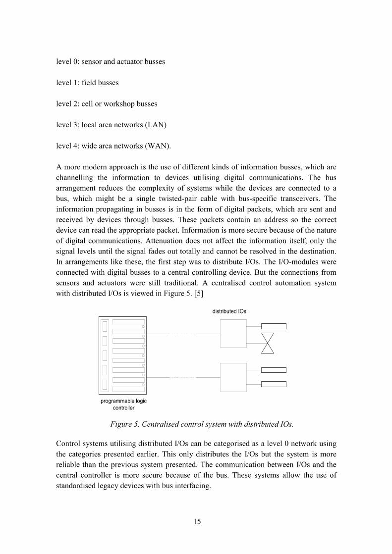
Automation has previously been based on the centralised controlling theme. A centralcontroller may have been a programmable-logic-controller, relay-logic, computer, andso on. Centralised controlling has made use of complicated wiring and obligatoryinstrumentation. Figure 4 shows the situation when using a centralised control. It caneasily be seen that this arrangement leads to a massive amount of wiring when thesystem is big. It is also harmful in big systems to allow sensor and actuator signals topropagate in long wires where some severe losses can occur. [5]
When better reliability and higher data speeds were demanded, digital communicationsand their network solutions were adopted. Generally the digital communicationnetworks can be categorised as follows [5]:
Sensors and actuators
programmable logiccontroller
Figure 4. Centralised control system.
15
level 0: sensor and actuator busses
level 1: field busses
level 2: cell or workshop busses
level 3: local area networks (LAN)
level 4: wide area networks (WAN).
A more modern approach is the use of different kinds of information busses, which arechannelling the information to devices utilising digital communications. The busarrangement reduces the complexity of systems while the devices are connected to abus, which might be a single twisted-pair cable with bus-specific transceivers. Theinformation propagating in busses is in the form of digital packets, which are sent andreceived by devices through busses. These packets contain an address so the correctdevice can read the appropriate packet. Information is more secure because of the natureof digital communications. Attenuation does not affect the information itself, only thesignal levels until the signal fades out totally and cannot be resolved in the destination.In arrangements like these, the first step was to distribute I/Os. The I/O-modules wereconnected with digital busses to a central controlling device. But the connections fromsensors and actuators were still traditional. A centralised control automation systemwith distributed I/Os is viewed in Figure 5. [5]
Control systems utilising distributed I/Os can be categorised as a level 0 network usingthe categories presented earlier. This only distributes the I/Os but the system is morereliable than the previous system presented. The communication between I/Os and thecentral controller is more secure because of the bus. These systems allow the use ofstandardised legacy devices with bus interfacing.
programmable logiccontroller
distributed IOs
Figure 5. Centralised control system with distributed IOs.
16
The intelligence is still centralised in the logic controller. Nowadays the development isheading for distributed intelligence. Intelligence itself is distributed to devicesthemselves. This forms a very robust system. A fully distributed system, as in bustopology, is presented in Figure 6. [4, pp. 438�456]
Devices contain the actuator or sensor itself with an intelligent part executingcontrolling and communicating tasks [4]. Devices communicate between each other bymeans of a bus. A bus delivers messages or data packets to a recipient. In networks,there are also other topologies that can be used: star, ring, and tree [6, pp. 158�160].Commonly in all topologies, a source sends a packet with the recipient's address to allconnected devices but only the addressed recipient reads the packet. A protocol is usedto avoid and detect collisions in the bus.
In level 3 and 4 the most common networks are Ethernet and TokenRing. Ethernet,typically used in computer networks, uses collision detection and carrier sensingtechnologies. Data is transmitted in the forms of packets containing data themselves aswell as addresses and other control information.
In the field of automation there are several implementations of automation busses.Every manufacturer seems to have their own solutions and application area. Such asProfibus, Bitbus, AsiBus, LonWorks, and so on, are in use. When moving between thelevels of networks, the amount of transferable data changes. In level 0 devices withdistributed I/O-units, the amount of transferred data is small and gets bigger towards thenetworks of level 4 which is typically an Ethernet-style network nowadays. This ispresented in Figure 7 [5].
Figure 6. Distributed control system in bus form.
17
2.3 Local Operating Network
The American Company Echelon has developed a distributed automation networkcalled LON (Local Operating Network) in the '80s. Echelon�s system utilises its self-developed protocol called LonTalk. The LON system contains independently operatingdevices which can communicate together [7]. LON can be referred to as a distributedsystem with intelligent devices. It has some features of fieldbus, sensorbus, anddevicebus. Simple sensors, actuators and even complex devices like PID-controllers,timers and so on are available to the LON network.
Devices in this standard use the LonTalk protocol. The LON-devices have amicroprocessor called the Neuronchip. The Neuronchip itself contains threemicroprocessors. There are two processors for communication and one for theapplication. The application processor handles the application itself and can bereferenced as a controlling unit as stated earlier. For transmitting data with otherdevices, two communication processors are used, each implementing different levels ofthe protocol stack. Chips are identified by a unique 48-bit ID-number. Devicescontaining the Neuronchip can be identified and accessed with this ID-number [7].
Neuronchip applications are programmed with a special implementation of the C-programming language called Neuron-C. It is an extension of ANSI-C including event
Figure 7. Network levels and amount of data transferred.
driven applications and special communication commands for LonTalk protocol�smessages, and is object oriented. Applications can be made on a conventionalmicroprocessor using the Neuronchip only as a communications processor. This widelyexpands the usability of the LonWorks network. In Figure 8, a basic construction of theLON device and basic architecture of the Neuronchip are presented.
The standard of the LonTalk protocol is �locked� in order to create a betterinteroperability between different vendor�s devices. Messaging between devices ispacket-based and is directed peer-to-peer. The packets find their destination mainly bythe Neuronchip�s ID-number. There is no need to know anything about the topology ofa network. Reconfigurations can be made in the network and packets still find their wayto their destination. Another communication processor called MAC, Media AccessControl, deals with accessing the network and actually implements layers 1�2 in the OSI-model. Using a special algorithm, this processor sends data packets while trying to avoidany collision with other packets. The MAC algorithm used in LON is quite similar as inEthernet. It uses randomised time slots when sending and retrying to send. [7]
2.3.1 Addressing in LON networks
In the LonTalk protocol, addressing is divided into hierarchies. These include domain,subnet, and node addressing. A device is also referred to as a node here. In this way it ispossible to address the entire domain, subnet or an individual node. A domain contains acollection of nodes forming a virtual network. Nodes can communicate only within thesame domain. A node containing the Neuronchip can be configured to belong to one or
CommunicationPort Media Access CPU Network CPU
I/O (Counters,Resources, Drivers,
etc.)Application CPU
Protocol Firmware(Layers 1-2)
Protocol Firmware(Layers 3-6)
Device SpecificProgram
RAM/ROM/EEPROM RAM/ROM/EEPROM
RAM/ROM/EEPROM
Neuron ChipNeuronID 01004DE52000
Transceiver
OptionalExternalMemory
I/OConditioning
Network
Figure 8. Main components in LON-device.
19
two domains. The node belonging into two domains may be used as a gateway betweendomains.
A domain is defined by the domain ID. A subnet is an entity in a domain containing upto 127 nodes; domains can contain 255 subnets at maximum. Subnets are discontinuedover routers. A subnet is tied more to the physical layout of the network. Nodes areconsidered as a single functional unit or LON device, which has assigned to it a nodeaddress. The node address is 7 bits so this gives 127 possible nodes per subnet. Inaddition, the device can be always addressed by its Neuron ID.
Logical groups can be formed in domains. Groups are formed without any regard fortheir physical location in the domain. A device can belong to 15 groups. Figure 9illustrates the addressing in LonTalk protocol.
Several kinds of address types are supported by the LonWorks protocol:
1. The physical address is included in every LON device in the form of Neuronchip�sID number.
2. The device address is a device�s address when the device is installed in a particularnetwork. A network installation tool creates the address. This address is divided intothree parts: domain ID, subnet ID, and node ID, each identifying a device in agreater entity.
3. The group address is used to identify a single group of devices.
Domain 1
Subnet 2Subnet 1
Subnet 4Subnet 3
Node 1
Group 1
Group 2
Domain 2
Figure 9. Addressing hierarchies in LonTalk protocol.
20
4. The broadcast address is used to broadcast messages to many devices in a subnet ofa domain. [8]
2.3.2 LonTalk protocol layers
LonTalk provides services in the six lowest (1�6) layers of the ISO/OSI reference
model. The seventh layer, the application layer, is defined by user programmed
automation. Services provided by the layers are presented in Table 1 [8].
reliabilityEnd-to-end acknowledgement, service type,packet sequencing, duplicate detecting
Session Control Request-response, authenticationPresentation Data interpretation Network variables, application messages,
foreign framesApplication Application
compatibilityStandard objects and types, configurationproperties, file transfer, network services
Due to the layered protocol, LonTalk is media-independent. The transfer media can bechanged by changing the transceiver in the LON device. There are many types availableranging from wired to wireless media. The cable-based media allows speeds of 10 Kbpsup to 1,25 Mbps depending on the network topology. The slowest connection of 10Kbps is used in powerline based networks with free topology. The highest speed isuseful in twisted pair cable networks with the bus topology. The speed of 78 Kbps canbe used in twisted pair free topology networks. Distances between nodes that can beused depend on topologies. Distances can vary from 130 m to 2700 m, which can beincreased with special repeaters. In wireless media, there are possibilities to use radiowaves and infrared light among others. In Table 2, properties of several wired networksthat are possible to use are presented. [8]
Table 1. OSI layers in LonTalk.
21
Table 2. Properties of wired LON networks.
Networktype
Media Bit rate Topology Max dist. Max no. of nodes
FTT-10A Twistedpair
78 kbps Free � bus, star,loop, othercombinations
500 m m with adoublyterminated bus
64
LPT-10 Twistedpair
78 kbps Free � bus, star,loop, othercombinations.Power to nodes issupplied withinthe same cable.
500 m freetopology; 2,700m with doublyterminated bus
32@100mA/node
64@50mA/node
128@25mA/node
TPT/XF-78
Twistedpair
78k bps Bus 1400 m(3 m stubs)
64
TPT/XF-1250
Twistedpair
1,25Mbps
Bus 130 m(0.3 m stubs)
64
PLT-10A Powerlines
10 kbps Free or bus;supports powerlines andunpoweredtwisted pair
Depends onattenuation andnoise in lines
32,385
2.3.3 Network variables
In the presentation layer, data is presented as network variables, where they representthe I/O of the device. Network variables are data that are formatted by the variabletypes. Variables define the data that are carried by LonTalk messages. There arevariable types for example for temperature, switch positions, frequency, and time.Currently, the amount of predefined variables exceeds 100. Data carried by a variablecan be addressed to a certain device by binding it. The automation applications aredefined by binding these variables. The device must be able to handle the data typebeing received. The variable types are standardised by the LonMark Association andcalled SNVTs, Standard Network Variable Types. The predefined variable types containa definition of units, and a range and a resolution for data. Therefore in the binding
22
process, variable types must be compatible when they are connected together. There areseparate variables for input and output uses. For example in digital input devices, whenan input event occurs, a variable is sent to the network and is received by a device ordevices to which the variable is bound. Bindings are usually done with graphicalconfiguration software, which presents bindings as lines leading from one graphicalobject to another, where the graphical objects re-present the devices. Configurationsettings are done by special configuration network variables. There are standardconfiguration property types available defining, for example, gain and other propertiesfor the PID controller. The use of these predefined properties and variables is meant fordevice manufacturers to make development easier. In the case of Figure 10, a simpleapplication is defined by two variable bindings.
The analogue/digital-input device has three output variables of types SNVT_switch,SNVT_volt and SNVT_time. The SNVT_switch is simple on/off information about thestate of the simple switch. The A/D-transformer digitises the voltage from thepotentiometer, and the digital information of the voltage is in the SNVT_volt formattedvariable. Time produced by the clock is transmitted in the variable of the format ofSNVT_time. In Figure 10, the time variable is not connected to anything. The Switchvariable is connected to a digital output device. When the state of the switch is changedin the input device, the Neuronchip formulates the data to be attached to the networkvariable and sends the variable to the network as a message. A message is also receivedby an output device, which reads and resolves the data and turns on the light bulb.
ApplicationAnalog/Digital Inputdevice
nvoswitch[0]SNVT_switch
Neuronchip
nvovoltage[0]SNVT_volt
Digital Output device
nviswitch[1]SNVT_switch
Neuronchip
A/D
Clock nvohoursSNVT_time
bindings
Analog Output device
nvivoltageSNVT_volt
Neuronchip
D/A
Figure 10. An application defined by variable bindings.
23
Voltage information about the state of the potentiometer is constantly transmitted to ananalogue output device, which controls the brightness of the light bulb, by the D/Atransformer. Properties of variable types are presented in Table 3 and Table 4 [9].
Table 3. Properties and fields of SNVT_switch variable.
Field Units Valid Range Notevalue 8 bit
percentage0 .. 100% Intensity as percentage of full scale,
resolution 0.5%state state 0 .. 1, 0xFF 0 means off, 1 means on, 0xFF means
undefined
Table 4. The properties of other variables.
Variable type Units Valid Range ResolutionSNVT_volt volts -3,276.8 .. 3,276.7 0.1 VSNVT_time_hour hours 0 .. 65535 hours 1 hour
2.3.4 Functional profiles
Functional profiles define standardised patterns for devices the way SNVTs definenetwork variable types. The pattern describes the application layer interface includingthe network variables, configuration properties and so on. A functional profile is genericand may be implemented by devices from different manufacturers. A profilestandardises the functions of devices, and not the actual devices [7]. The use of profilesin device design helps device manufacturers to make devices interoperable. A typicalfunctional profile for a simple switch as presented in a standard LonMark style ispresented in Figure 11 [10].
nvoSwitchFbSNVT_switchnv2 nvoSetting
SNVT_settingnv3
SwitchObject Type 3200
nvoSwitchSNVT_switchnv1
MandatoryNetworkVariables
OptionalNetworkVariables
Configuration PropertiesMandatory/Optional
InputNetworkVariables
OutputNetworkVariables
Figure 11. Graphical illustration of the switch�s functional profile.
24
The switching device contains one mandatory network variable, which is of the type ofSNVT_switch. The variable is named as nvoSwitch. It is output information about thestate of the hardware switch. Optional variables contain two variables, one to form afeedback loop and another for optional information output for external controllerdevices. In this profile, configuration properties contain only optional ones likeminimum and maximum send times for network output. Only a mandatory variable isnvoSwitch. [10]
2.3.5 Self-documentation and -identification
LON devices are self-documenting and -identifying devices. The devices holdinformation about the device itself in their Neuronchips. Self-documentationinformation includes [11]:
1. The manufacturer of the device,
2. the type of the device,
3. the ID of the Neuronchip within the device,
4. any functional profiles supported by the device, and
5. type information for any additional network variables supported outside of thestandard objects.
Self-documentation data can be accessed by network management tools. This helps theinstallation tasks because the device-specific information is downloadable from thedevice itself when it is connected to the network. Self-identification signifies the storedNeuron ID number, which identifies the devices as stated earlier. Data is presented inXIFs, External Interface Files, which presents all the self-documentation data. The samedata is stored in the device�s Neuronchip but is also usually available as an external file.
In the device design phase, an XIF file is compiled into a binary file, which is fed to theNeuronchip. This binary file can be retrieved and the information can be read. Figure 12shows an example where are two variables, nviNdRequest and nvoNdStatus, and theirparameters defined.
3. Modern home automationThe visions and new technologies of modern home automation have been presentedwidely and quite frequently. The major improvement has been the adoption of busnetworked devices. This makes obsolete the need for complicated wiring arrangements.The bus networks might be a crucial networking method for homebuilders because of itssimple wiring. There is a wide range of different technologies and standards available inthis field. The visions presented, contains the ability to control homes distantly fromusers� terminals. This sets a demand also for homes to be connected somehow to outsideworld. Nowadays this usually means a standard TCP/IP network connection in someform.
Now there is made a distinction between two, possibly incompatible networks, whichare categorised as RAN and LAN on the basis of their coverage area. RAN, ResidentialArea Network, means networks used in residential buildings and it connects together thedevices located in homes or other residential areas. Different types of controlautomation networks, like LonWorks, are categorised as RAN. LAN groups all thenetworks, in this case in homes, together. Furthermore these LANs might be connectedto an even bigger networks like the Internet. The Internet is usually referred as a WAN,Wide Area Network.
While there is no common standard in the foreseeable future in RANs, all the devicesconnected to different networks are practically invisible to each other. When keeping inmind that LAN and RAN must be connected together somehow to allow access fromoutside to an automation device level, an interconnection facility is needed. Its functionis to tie flows of information from different networks together and allow data exchangebetween them. It has been also recognised by several standardisation proposal likeOSGi [12] and ISO/IEC SC25 [13] that there is a need for a common interconnectionapparatus. This apparatus which is called a residential gateway or in-home-server in thiswork, makes it possible for all the networks to communicate transparently. Figure 13illustrates the roles of the RAN, LAN, WAN and the in-home-server. [14,15]
27
3.1 Residential area networks and local area networks
The viewpoint in RANs here, is on the automation. There are several other uses forRANs like audio, video and computer networking. Home automation networking hasevolved from a centralised control scheme towards to a distributed intelligence evenmore rapidly than in the industrial world. In the field of home automation the costs inwiring is an important factor. Some of the RAN technologies have options to useexisting wires like telephone lines and power lines. The power line networking methodhas some problems like interference from devices consuming power from the network[16]. The biggest advance this technology is the costs of wire installations, while thewiring usually exists. Nowadays the needs of future networking have been takenseriously and wires have been installed during the building process. Of course there aresome wireless technologies available even today which are naturally independent ofnetwork wiring.
There are a wide range of technologies and standards available. The most usualappliances available for these networks are lighting devices like switches and lights.These can lead towards other simple on/off control tasks for turning on and offelectricity in other home devices. The other uses could include home security, heat andventilation controlling. The possibilities are wide. The LON network handles the devicelevel communications, or in other words acts as a RAN, in the environment of thiswork. Below is presented a few networking technologies. Some of them are alsoapplicable as a RAN and network connection to the outside world
Figure 13. RAN, LAN, WAN and in-home-server.
RAN
LAN
WAN
In-home-server
28
- HomeRF/SWAP:
The Home Radio Frequency working group has presented the Shared WirelessAccess Protocol. Devices utilising this protocol, are designed to use the licensefree 2.4 GHz radio frequency band. The HomeRF uses a dual protocol stack:DECT, Digital European Cordless Telephone, for voice, and 802.11 packets fordata [17]. The modulation type is frequency-shift keying, FSK, at up to 2 Mbps. Anetwork can consist of up to 127 nodes. Distributed and central control schemesare supported. The maximum usable range is 50 meters. [18]
- Bluetooth:
Bluetooth is an open specification for short-range wireless communication of dataand voice utilising short-range radio links. It operates on the same 2.4 GHz bandas HomeRF. Bluetooth uses fast acknowledgement and frequency hopping withGFSK, Gaussian Frequency Shift Keying, modulation [19, p. 22]. This radio linksystem is largely intended for mobile devices to replace wires but is usable inother applications too. [19, pp. 41�42]
- HomePNA:
The Home Phone Networking Alliance is presenting the use of existing phonelines to be used as networking media. Devices are connected to wall telephonejacks and are operated in an Ethernet-fashion using CSMA/CD scheme. The datatransmissions are located above the voice frequencies. The current HPNA 2.0version reaches the throughput rate of 32 Mbps. [20]
- HTTP:
It would be possible to handle automation networking at device level with anembedded HTTP-server, while there are several embedded HTTP/TCP/IP serversolutions available. One of those is the WebChip developed in a research projectby VTT Electornics, which is implemented totally in hardware. In this kind ofsolution for example Ethernet networking technology could be used. [21]
- EIB:
EIB, European Installation Bus, is a proprietary automation networking system. Itallows networking on several media like twisted pair, power line, wireless andinfrared. Transmission speeds varies from 1200 bps up to 10 Mbps. Devicesavailable in this standard include security, household appliances, measurementand control equipment. [22]
29
Typically communications to the outside world is handled by the TCP/IP protocolwhich can be considered as a defacto standard nowadays while there are available manywired and wireless interconnection technologies for physical implementation. Thechoice of external networking technology is mostly based on the local circumstancesand already available wirings. The reference [16, p. 8] discusses these issues and seesEthernet as a best solution for interconnection to outside world. Ethernet is widely inuse in computer networks. With special adapters and routers it is possible to useEthernet network as an automation network for special automation devices. LonWorksis also routable via Ethernet. Ethernet can be brought home with a wide variety ofnetworking technologies. A typical solution for homes includes connection throughphone lines while there are seldomly fixed network connections available in sparselypopulated areas. Below are described a few methods for TCP/IP networks to bepropagated into homes:
- Powerline:
This method allows a data transmissions through a power line. The mainadvantage of this technology is the use of existing wires. The biggest problems arerelated to the interference received from those appliances using power from thesame line. There are several automation bus technologies offering this networkingmethod as an alternative. The outside networking with this connection technologyhas some features that need to be investigated more. Power companies have beenusing power lines as low speed controlling networks for a long time. When thespeed is brought up to a level appropriate for computer networking severeinterference will occur in the HF radio bands and furthermore other technologiesavailable will make this method obsolete [23].
- Cable modems:
Cable modems offer data networking through cable television networks. The datatransmission is located on unused channels of the cable. Usually these modemsoffer Ethernet connection for the computer. The highest speed available atmaximum is in theory 5 Mbps while in practice the usable speed is 1 Mbps. Thetransmission is asymmetric which means that in average the data throughput fromnetwork to homes is higher and from homes to network lower. [24]
- xDSL:
xDSL, Digital Subscriber Line, technologies are offering point-to-point networkaccess for digital communications like data, video and voice. This is a technologyto bring digital communication from a service provider�s switch to homes whilethe communication between service providers is handled with other technologies.These technologies are using standard POTS twisted copper wire as the transfer
30
media on a local loop. The x stands for the various kind of digital subscribertechnologies, including ADSL, R-ADSL, HDSL etc. Nowadays technologies likeADSL, Asymmetric Digital Subscriber Line, are available commonly forhouseholds� Internet access. The transfer method is asymmetric while the transferspeed is higher into homes and lower from homes. [25]
3.2 Residential gateways
A device is needed to integrate the home and outside networks together and at the sametime offer a gateway for accessing the home or accessing outside network from homes.It is also seen that this device is located in homes and is using robust hardware and asreliable software as is possible. From the viewpoint of this work, the residential gatewayor, as referred to from now on in this work, in-home-server offers an access point fromoutside the homes to the automation devices located in the homes. It is also consideredthat it would be able to offer other services like TV, telephone networking, printing etc.in addition to a home automation service. While the in-home-server performs router,firewall and gateway functions, it is expected to handle functions at a network levellisted below [14]:
- Media translation:Wherever the access network and RANs physical media differ, a translationfunction is required.
- Speed matching:Where network speeds differ, buffering is required to avoid overwhelming theslower network.
- IP address acquisition:Terminal equipment requires an unambiguous address for addressing an accessnetwork.
- Protocol coexistence:Where protocols are encapsulated or multiplexed with one another, de-encapsulating or de-multiplexing will be required.
- Filtering:Perform firewall functions to prevent unauthorised packets from entering orleaving the home.
- Authentication and encryption:Ensure privacy and security of transactions, as well as authenticate customers forservices.
31
- System management:Provide functions such as fault management, diagnostics, accounting andperformance management.
The physical architecture of an in-home-server has been proposed by the ResidentialGateway working group. The in-home-server contains five functional componentswhich are a common bus, power supplies, in-home network interfaces, service providernetwork interfaces and processing support. The common bus serves as a commonbackbone of the system. It provides a communication path for all other components.Power supplies supply the required electrical power for all the components included inin-home-server. An un-interruptible power supply, UPS, could be included for safeoperation even during the power cuts. In-home network interfaces provide an interfacefor RANs like LonWorks automation networks. Other services like cable TV andtelephone can be included. Service provider network interfaces offer an access to theoutside world networks or WANs for the in-home-server. The processing support offersgeneral processing capabilities for the system. It can contain general purpose processorsand processors specialised for a particular purpose. A traditional PC platform is seen asan inadequate solution for in-home-server technology [15], but the final decision for theplatform technology is left to others and in this work the PC platform is used. In Figure14 [14] the architecture of the in-home-server architecture is illustrated. [14]
NonvolatileStorage
General purposeprocessor,memory
Securityprocessor(Firewall)
MPEG processor
ADSL
ISDN
Twisted Pair
Satellite
Video/Video-on-demand
Ethernet
POTS
LonWorks
Common
Bus
In-home NetworkInterfaces
Service ProviderNetwork Interfaces
Processing Support
Utility PowerSource
UninterruptiblePower Supply
Figure 14. Architecture of the in-home-server.
32
3.3 Current residential gateway standards
There are several standardisation efforts going on. The most noteworthy seems to be theISO/IEC Residential Gateway Model [13] and the Open Services Gateway initiative,OSGi [12]. The ISO/IEC model supports two approaches to in-home-serverdeployment: centralised and distributed. The centralised set-up contains all serverfunctions in a single node. The distributed mode allows the distribution of functions inseveral nodes which all might be located in diverse locations. The ISO/IEC workinggroup tries to define RGIP, Residential Gateway Interchange Protocol, which can beused as an interchange format between different networks. All the in-cominginformation is translated to RGIP format and fed to destinations which again translate itinto their own formats. This protocol can be considered as a part of the common buspresented in general in-home-server architecture earlier. The data streams in the homeaccess line, or connection between in-home-server and WAN, has been divided intothree functional parts in this model, each has been reserved for certain purposes:
- User Services Functions:This channel provides all user specific data like video, audio, IP packets, controland management signals for service providers.
- Residential Gateway Functions:This path is used for maintenance of in-home-server�s hardware and set-up.
- Access Line Termination Functions:This path is reserved for access provider, like ISPs, to control the access line.
The work around this ISO/IEC model is still unfinished and the schedule of itscompletion is unknown. [12]
The OSG initiative is supported by several large companies like IBM, Motorola andLucent. They hope to get a standard available for this kind of technologies while theneed of standards is recognised for the market to soar in home automation systems. TheOSGi is a collection of Java APIs which define operations and functions required froman in-home-server. The specification includes standard Java APIs where possible likeJINI. The APIs are meant for service providers, network operators, device makers andappliance manufacturers for a vendor-neutral interface. This specification does notrespond to hardware requirements but tries to specify a platform independent system.The specified system includes Device Access Manager which is responsible formanaging networks and other devices under its control. In addition to that it offersservices for hardware included with the in-home-server. The services it offers for thehardware are dynamically loaded on demand. It must support automatic discovery of
33
hardware which is added and furthermore load the services needed. The OSGi in-home-server supports several general services needed for full operation of the server. Theseincludes the following:
- Log Service:The log service is involved in the upkeep of diverse logs with information of useractions and system state.
- HTTPService:OSGi sees that many services offered to users and service providers, will be basedon web protocols. Therefore support for this is added using standard Java APIs.
- Client Access Service:This service provides access for end users in the home. It offers capabilities thatare not available through HTTPService and is located in the homes while theHTTPService can be used also remotely.
- Configuration Data Service:Configuration data service will be responsible for configuring other servicesrunning on the in-home-server. A common service API for services is offered tostore and access configuration data for remote administrator.
- Persistent Data Service:This service is used by other services that will store and retrieve information thatpersists beyond the life of the service and that can be shared with other servicestoo. Use of this centralised data service make unnecessary the services� ownimplementations of data services.
When paying regard to these two standard initiatives, it seems that OSGi is morenoteworthy on the basis of its background organisations. The OSGi has also chosenJava as the implementation language. This opens to it a wide possibilities of interestingJava technologies. Currently the OSGi supports several RAN technologies likeBluetooth, CAL, CEBus, HAVi, Home API, HomePNA, HomePnP, HomeRF,LonWorks, VESA etc. [12]
3.4 Conclusions of this chapter
The most crucial technologies presented here are the concept of a residential gateway orin-home-server and some RAN technologies. The concept of an in-home-server is avery important piece of infrastructure when controlling home devices outside the home.
34
It allows the use of multiple incompatible RANs and further routes them to the outsideworld. These abilities are very basic requirements in these kind of arrangements, whereapplications are developed elsewhere and even used outside the homes. When thinkingof the basic problem, the problem of the device description and remote applicationdevelopment, researched in this work any of the currently available and presentedresidential gateway solutions does not make respond.
The demand for RANs contains the availability of a hardware and software interface fora use in the in-home-server to control them. Most of the RAN technologies do not haveself-documentation abilities as the LON has, although device identification addressingis an elementary function of almost all networked devices. Of course the self-documentation can be handled in some other way like in the form of a centraliseddatabase, where the data is collected by the identification information. But for the timebeing the information concerning the device distributed to the distributed devices is themost elegant solution.
35
4. Technologies for presenting devicedescriptions
The interface of a device can be retrieved from the device itself. This data is presentedin this case using LonWorks� own data formats. In this chapter the ways of presentingand storing this data in a more general form for use in other instances than LonWorks�own are studied. As a storage technology XML, JavaBeans and relational databases areconsidered, as they offer mechanisms required in this prototype. Finally, one of thesetechnologies is chosen to be used in the prototype.
4.1 XML-presentation
XML, Extensible Mark-up Language, is a mark-up language used for presenting dataand its structures. Actually XML is not really a language, but a standard for creatingother application specific languages meeting the XML criteria. Like HTML, XML is asubset of SGML. Furthermore XML is most usable as a data interchange format. UnlikeHTML, it does only define the data not what it looks like. The complexity of SGML isreduced as much as possible when XML has been developed. XML is compatible withSGML but only upwards. [26, p. 13]
Physically the XML document is a hierarchical text file with tags and the data itself.Content elements are separated by the tags and they form a tree with leaves andbranches. Tags specify the meaning or the label of the data followed. It is up to the useror the application how the tags are named and what kind of hierarchy they follow. Themost essential part of the interchangeability is the use of ordinary text file to store thedocuments. To make interchanging easier the XML documents can be formed into another XML document or into a totally different kind of file with the use of style sheetlanguages like XSLT. XSLT, extensible stylesheet language for transformations, is alanguage derived from XML and is a smaller version of the more complex XSLlanguage. [26, p. 18, p. 133]
4.1.1 Structure of the XML document
The structure of the XML document can be considered as a hierarchical tree withbranches and leaves or parent nodes and their child nodes with siblings. The tags andthe information relevant to the tags are called elements. The document has a rootelement, which is a parent element of all other elements in the document. Therefore allthe other elements in the document are children of the root element. The children mighthave again children and siblings. Siblings are located on the same level or in other
36
words they have the same parent. Figure 15, shows the hierarchical tree structure of asimple XML document presenting a simple document for names. [26, pp. 18�20]
4.1.2 Structure of the elements
Elements contain the information itself and the information, which tags the data.Therefore the tags give name to the information. To form a well formed XML documentelements must have a start and end tag, which must match the start tag. The tag namingconventions in the XML standard are very open, but a few rules should be followed inorder to have a well formed document like the names should always start with a letter,and to keep in mind the case-sensitivity of the XML.
The name of the tag is placed inside of < and > characters to form a tag. The tag mightcontain attributes. The name of the attribute with = sign and following quoted value isplaced after the tag name in side the < and > characters. The element�s informationitself, the content element, is placed after the start tag. The end tag closes the element,but the elements cannot overlap, therefore the end tags must be in the proper order tomaintain desired the hierarchical order. Figure 16 presents an example of the documentof names. [26, pp. 27�44]
person
first_name
middle_name
last_name
names
Element
parentalrelationship
parentalrelationship
siblingrelationship
siblingrelationship
Figure 15. Structure of a XML document.
37
4.2 Software component technology
Software objects, which are self-contained entities, usually encapsulate data and a set ofoperations, which manipulate that data. Usually objects reside in a single program anddo not exist as separate entities when the program is compiled. The softwarecomponents are the independent and self-managing parts of a system, which separatesthem from the objects. Furthermore these components are pre-developed before theactual application development takes place. The actual applications can be assembledfrom these pieces. There are several component-based technologies available nowadayslike Microsoft�s ActiveX and Sun�s JavaBeans based on the Java platform. [27, 28]
4.2.1 JavaBeans components
In the Java platform applications created using JavaBean components are developedwith special visual builder tools. Tools visually manipulate a collection of desiredcomponents to form a final application. The components� events and properties areconnected visually together to achieve the desired actions and state changes. As statedearlier software components must expose their interface to the user. So the user knowshow to use and what kind of properties are enclosed in that specific JavaBean whencomposing a new application. Internally JavaBeans may vary greatly but commonlythey must meet a few JavaBean concepts to be usable as a JavaBean component:
- Introspection:Beans must support introspection to allow builder tools to discover the entire bean�sfeatures including properties, methods and events. Features of the bean can therefore
Figure 16. Simple XML document.
<person><first_name>
Tommi</first_name><middle_name>
Niilo</middle_name><middle_name>
Henrik</middle_name><last_name>
Aihkisalo</last_name>
</person>
38
be exposed to the developer. Introspection can be achieved by two methods: usingcertain naming conventions or creating a special Bean Information class.
- Customisation:A beans� properties must be customisable to allow a user to alter the appearanceand behaviour of a bean.
- Events:Beans use events to communicate with other Beans. Beans can fire events andregister as a listener to certain events. Events that Bean can fire and handle mustbe exposed to the user.
- Persistence:Beans must be able to save and restore their state. Once changed and saved, theproperty must be able to be retrieved. [27]
4.2.2 JavaBeans as a collection of information
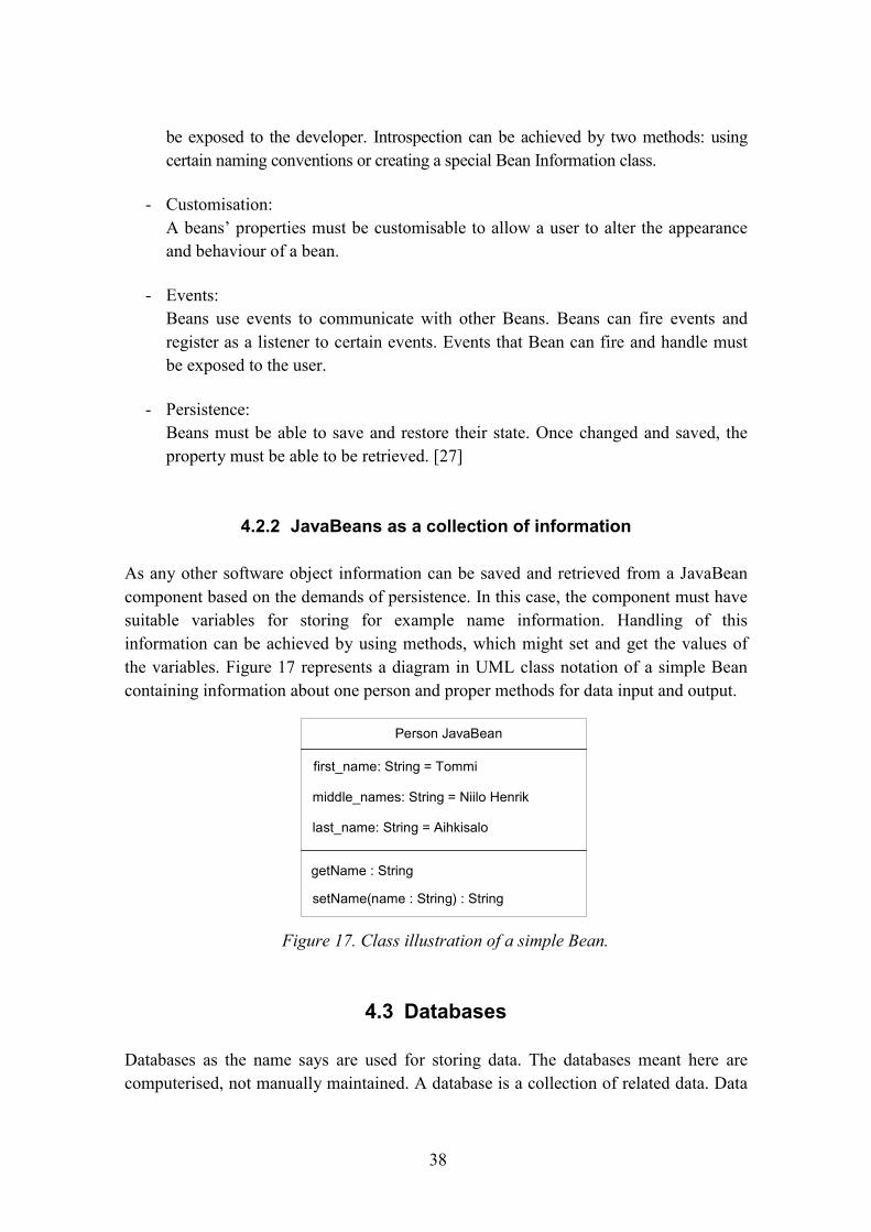
As any other software object information can be saved and retrieved from a JavaBeancomponent based on the demands of persistence. In this case, the component must havesuitable variables for storing for example name information. Handling of thisinformation can be achieved by using methods, which might set and get the values ofthe variables. Figure 17 represents a diagram in UML class notation of a simple Beancontaining information about one person and proper methods for data input and output.
4.3 Databases
Databases as the name says are used for storing data. The databases meant here arecomputerised, not manually maintained. A database is a collection of related data. Data
Person JavaBean
first_name: String = Tommi
middle_names: String = Niilo Henrik
last_name: String = Aihkisalo
setName(name : String) : String
getName : String
Figure 17. Class illustration of a simple Bean.
39
as it is used here means all recordable data, which can be names, addresses and so on. Adatabase has the following implicit properties [29]:
- A database represents aspects of the real world. When the real world changes,changes are reflected in the database.
- A database is a logically coherent collection of data with inherent meaning.
- A database is designed, built and populated with data for a specific purpose.
This means that a database has some source where data are collected from, data isrelated somehow to events in the real world and someone is maintaining and using thedata stored in the database [29].
Data stored in databases are formed as files containing records, which again containdata elements. The form of data in elements are defined by data types telling the type ofthe specific element e.g. name field is defined as a string of alphabetic characters. Thesedeclare the structure of the data used in a database. Figure 18 presents simple filescontaining records and data elements in a name and address database.
To form a complete database system a database management system is needed. This is acollection of programs to allow users to create and maintain a database. Tasks beingprocessed through the database management system include definition, construction andmanipulation of a database. Definition involves creating files, records and data elementsand all kind of properties needed to form a database. Constructing is the task of storingthe data itself to a database. Managing involves querying, updating and forming reportsfrom the data saved in a database. [29]
element name
record
file
file
data elementname and address
database
person first_name middle_names last_name
Tommi Niilo Henrik Aihkisalo
id
0
Kiia Sarianna Aihkisalo1
address street postal town
Ollinkehä 8 F 92120 Raahe
per_id
0
Savontie 18 A 9 78300 Varkaus1
id
0
1
Figure 18. Example files and records in a name and address database.
40
4.4 Evaluation of description technologies
The need for presenting information about interfaces of the devices has raised thequestion, what kind of technology is going to be used to present them in terms ofgeneral usability. All the technologies have their own advantages and disadvantages.These will be considered here and one technology will be chosen. In general the chosentechnology should be easy to use both in storing the data and retrieving it. Furthermorethe speed of transferring descriptions over the network and availability of tools formanipulation are important features. Therefore the categories of requirements forevaluating each technology are presented as listed below:
- Availability of toolsThis describes the availability of tools for each technology. This can include the APIand other development tools.
- Ease of dynamic creationThis describes the ease of the dynamic description creation process using eachtechnology. Using one technology it might be easy to dynamically create newdescriptions of automation platform than with others.
Need of further processingHere the need for further processing is evaluated. Further processing means theactions needed before the description can be taken in use.
- Platform independenceHere the technology is evaluated for its usability in multiple processing platformswithout excessive translations.
- Simplicity of formatThis describes the simplicity of each technology�s format. Some technologies mighthave a simple format in which to store information while others are morecomplicated.
- Speed of transferThis describes the speed of transfer over the network of descriptions based on eachtechnology. Some of the technologies might have more control data around theactual description information.
Using these requirements each technology has been rated from the viewpoint of thiswork and presented in Table 5. The each category is rated as + or -. The + means thattechnology fills the demands well in this category and - that it fills them insufficiently.
41
Table 5. The evaluation of each technology.
Requirement XML JavaBeans Database
Availability of tools + + +
Ease of dynamic creation + - +
Need of further processing - + -
Platform independence + + -
Simplicity of format + - -
Speed of transfer + - +
Based on this table, XML seems to be the best choice to be used in the prototype as adevice description method. Its weak point is the need of further processing to haveusable descriptions. The availability of tools is good while there are plenty of APIs andtools available. It is also easy to dynamically add or create new information files withXML and databases. This does not involve JavaBeans because the dynamic compilationand coding is not well supported. All the technologies are platform independent exceptthe database. Database queries can be made from almost any platform and data itselfcan be transferred but the transfer of the actual database program is difficult. The formatof data is most simple and compact in XML format. This correlates little with the speedof transfer. The XML descriptions are small and therefore easy to transfer over thenetwork. The JavaBeans software components might form large entities which are slowto transmit.
42
5. Distribution technologiesThis chapter reviews all the distribution technologies applicable to the prototype.Technologies that are taken in consideration are Java RMI, Jini and CORBA.
Distribution generally in computer science means that computing tasks are distributed toa group of computers. Computers are networked together with a network. Thecomputers are using services that are located in some other computer. Usuallycomputers offering services are referred to as servers and those using them are referredto as clients. In the networked community of the computers, the uses of the services takeplace over the networks. Using the services is made transparent to the user. Thereforenetwork traffic is usually hidden under the upper layers of applications.
5.1 Open Distributed Processing reference model
Due to the development of computer networking, interconnecting of computer systemcan be realised efficiently and sensibly. There have been many instances of developingdifferent kinds of distribution solutions. A particular reference point in this area is ISO�sRM-ODP, Reference Model � Open Distributed Processing, which defines a frameworkfor standards. It can be categorised as a standard for standards. As it provides only a setof concepts for the distributed systems, not any ready standards or solutions. The basicconcepts that RM-ODP offers are: an object-oriented approach, viewpoints andviewpoint models, distribution transparency and RM-ODP functions. [30]
RM-ODP defines viewpoints and viewpoint models for describing distributed systems.Each of them describes the system from its own viewpoint in a different scale or scope.This provides a set of concepts, structures and rules for each viewpoint. The referencemodel defines five different viewpoints:
- Enterprise Viewpoint, which defines purpose, scope and policies of the system
- Information Viewpoint for semantics of information and information processing
- Computational Viewpoint for functional partitioning of the system
- Engineering Viewpoint for defining infrastructures required to support distribution
- Technology Viewpoint for defining technologies in implementation
Transparency, which hides the details of distribution from the user, has been defined inRM-ODP in eight categories. Transparencies create an illusion of a singleheterogeneous computer system while using a single remote console. Defined
43
transparencies include such as access transparency which hides remote procedurecalling mechanisms and differences in data representation, location transparency masksthe addressing and the difference between local and remote, etc. These were justexamples among the many other types of transparencies to point out the essentiality ofit.
The collection of functions is represented in the RM-ODP that is needed to form a fullyfunctional distributed system. The functions are categorised to the management, co-ordination, repository and the security categories. [30, 31]
5.2 Engineering viewpoint
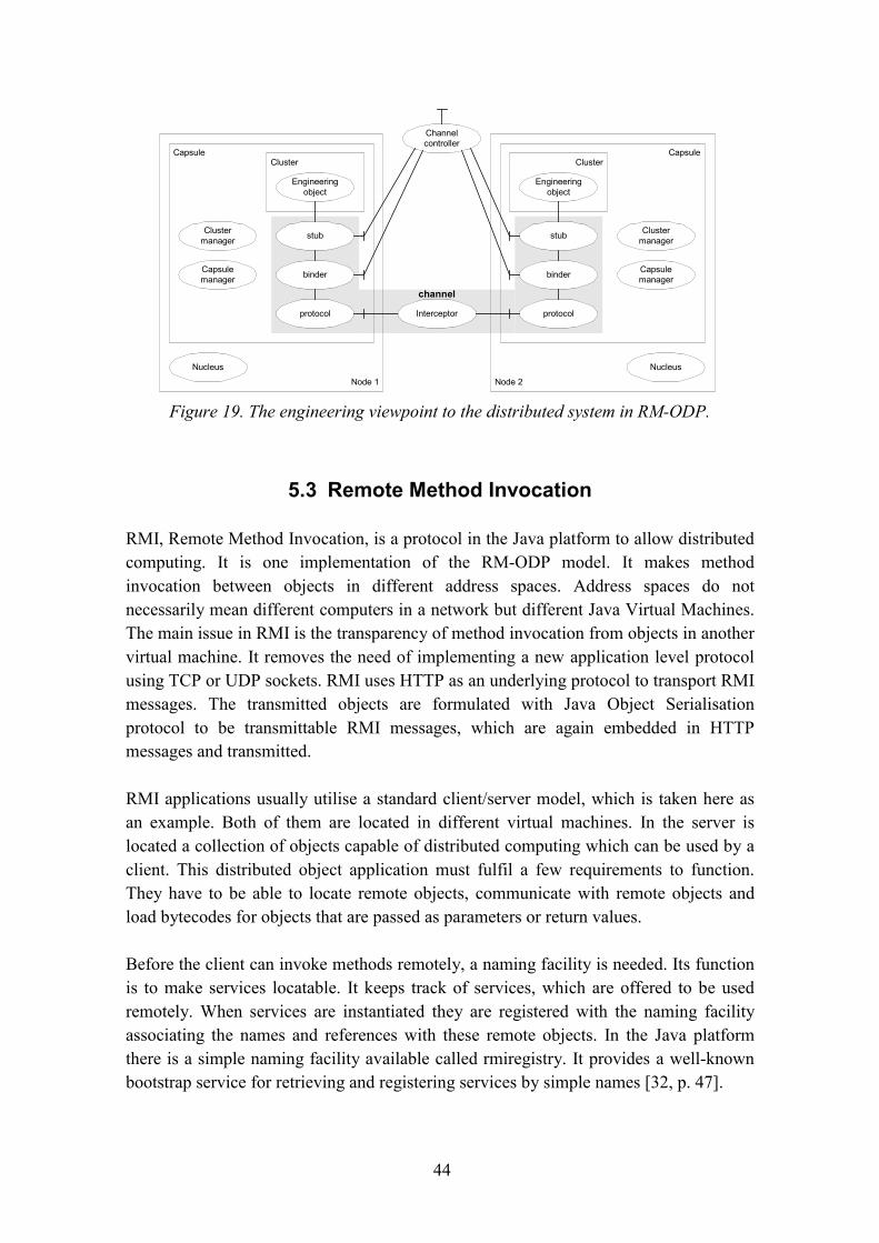
The engineering viewpoint describes the infrastructures required to support distributionor design of the distribution-oriented aspects of an ODP system. The reference modeldefines an engineering language, terminology, and procedures needed for variousactions like creating a communication channel. The main entities it prescribes areclusters, capsules, nodes and channels.
The main component in this terminology is a node. Engineering objects, services, alongwith their processing resources are grouped into nodes. Consequently a node can bethought of as representing a single computing system. The node is controlled by anucleus, which offers the operating system�s services like timing.
Capsules and clusters are containers of engineering objects. The capsules can containmany objects while they are arranged into smaller entities, clusters. The capsulecontains clusters, which contain a set of related engineering objects. This arrangementmakes manipulation and interaction between objects easier for the smaller entities.
Channels provide a mechanism for remote engineering objects and services, tocommunicate together. To maintain communications in a channel three objects areneeded. Stub objects are concerned with how the information transferred. The stubsinteract directly with the object needing communications, while they marshal and un-marshal parameters, logging the interactions. Consequently it can be said that stubsoffer transparency when it involves some knowledge of the application semantics.Binders and protocol objects are more like messengers, which only transport themessages bit streams. The binders establish the binding between services when thechannel is created and maintain the integrity of the channel. Protocol objects provide theactual communication between7 binders and while implementing the communicationprotocol used. Figure 19 [30, p. 35] shows the engineering viewpoint of a simpledistributed system. [30, p. 24�30]
44
5.3 Remote Method Invocation
RMI, Remote Method Invocation, is a protocol in the Java platform to allow distributedcomputing. It is one implementation of the RM-ODP model. It makes methodinvocation between objects in different address spaces. Address spaces do notnecessarily mean different computers in a network but different Java Virtual Machines.The main issue in RMI is the transparency of method invocation from objects in anothervirtual machine. It removes the need of implementing a new application level protocolusing TCP or UDP sockets. RMI uses HTTP as an underlying protocol to transport RMImessages. The transmitted objects are formulated with Java Object Serialisationprotocol to be transmittable RMI messages, which are again embedded in HTTPmessages and transmitted.
RMI applications usually utilise a standard client/server model, which is taken here asan example. Both of them are located in different virtual machines. In the server islocated a collection of objects capable of distributed computing which can be used by aclient. This distributed object application must fulfil a few requirements to function.They have to be able to locate remote objects, communicate with remote objects andload bytecodes for objects that are passed as parameters or return values.
Before the client can invoke methods remotely, a naming facility is needed. Its functionis to make services locatable. It keeps track of services, which are offered to be usedremotely. When services are instantiated they are registered with the naming facilityassociating the names and references with these remote objects. In the Java platformthere is a simple naming facility available called rmiregistry. It provides a well-knownbootstrap service for retrieving and registering services by simple names [32, p. 47].
Cluster
Nucleus
Clustermanager
Capsulemanager
Engineeringobject
stub
binder
protocol
Capsule
Node 1
Cluster
Nucleus
Clustermanager
Capsulemanager
Engineeringobject
stub
binder
protocol
Capsule
Node 2
channel
Interceptor
Channelcontroller
Figure 19. The engineering viewpoint to the distributed system in RM-ODP.
45
The function order for the client is firstly to locate the registry service. Using a knownURL, the registry service is located. The client receives a reference from the registry forthe service it is looking for. With this reference it can call the service from the server.Standard web servers are used for transmitting the actual bytecodes of objects inparameter passes, returning values and receiving remote objects. Figure 20 [32, p. 4]illustrates the structure of distribution in a simple distributed client/server applicationusing RMI.
The actual communication with remote objects is done using stubs and skeletons. Thestub is a counterpart for the skeleton, which resides with the remote object. The skeletonand the remote object are referred here as a remote object. The client side uses stubs,which is a local representative for the remote object. It can be considered as a proxy too.It is responsible for hiding details of communications between objects and therefore itimplements the transparency and the RMI protocol. The client invokes the methods onthe stub through an interface describing the remote object. The stub carries out themethod call to the remote object. Its counter part in communication is the skeletonlocated on the server�s side. The communications is done using the RMI protocol. Themain tasks of the stub are:
- Connection initiation with the remote object,
- marshalling the parameters,
- un-marshalling the return values and exceptions, and
- returning values to the client.
Figure 20. A structure of distribution in a simple client/server application utilising RMI.
client
web serverweb server
registry
server
RMI RMI
RMI
URLprotocol
URLprotocol
URLprotocol
46
The skeleton that is located on the server�s side is quite similar to the stub. Itsresponsibilities are to communicate with the stub and to implement the actual RMIprotocol. As the stub, the skeleton implements the same interface as the remote object.It has the same responsibilities as the stub and it does not have to initiatecommunications. In newer Java platform releases the usage of the skeletons is replacedwith an additional stub protocol. Figure 21 illustrates the RMI between the client andthe server utilising stubs and skeletons. [32]
5.4 Jini
The Jini architecture brings a new kind of flexibility to distributed computing. It allowsa spontaneous networking of devices, software services and hard/softwarecombinations. Rather than client/server architecture Jini is decentralised a systemproviding reliable networking. Adding or removing any of these components is possiblewithout the need to update others in the community they form. The important part ofJini architecture is a lookup service. It is a service that keeps track on the servicesavailable in the network community. Services are registered to the lookup withparameters telling the type and other properties of the services. So services can join orleave the network community anytime and the lookup service is updated to a newsituation. All the services in the community are aware of each other and they can useeach other. The size of communities has not been restricted, but a reasonable size mustbe considered. To allow scalability in Jini networking a concept of federations areadopted. Federations are collections of smaller communities. Communities can use theservices of other communities. This can be achieved by adding one�s lookup service tothe other�s lookup, while the lookup service itself is a Jini service. Therefore theservices can be used crossover. This kind of hierarchy and the main elements in Jiniconcept is presented in Figure 22.
Figure 21. The basic structure of the client and server with RMI distributed service.
client server
stub skeleton remote objectremoteobject
interface
clientapplication
RMI channel
47
Services are used through proxies, which provide all the code to use the desired service.The communications between the service user and the service implementation ishandled by the proxy. The proxy�s code is dynamically downloaded to the client. So theuser does not have to know anything about the implementation of the service. The onlyrequirement for the instance using the service, is to know the service�s interface. Theproxies are stored to the lookup service, when the service is started. The proxies ofservices desired to be offered for use, are uploaded to the lookup service. When theservice user is looking for a suitable service he must search the lookup service forservice meeting the requirements. After the proxy is found and downloaded, the servicecan be used. The process to find the lookup service is referred to by discovery in the Jiniconcept. There is no need to know any fixed addresses of this service. The lookupservice acts like a beacon because it periodically sends messages informing of itsexistence. This is done also by the client when looking for and discovering the lookup.
There are different types of proxies that can be used. One type of proxies is a proxy thatperforms the services itself. Consequently the service need only be a software serviceand it does not required any external resources. The second type is a proxy using someexternal resources. It can be implemented as an RMI stub using services somewhereelse. Its only function is to communicate with the service implementation. This kind ofproxy can represent e.g. a hardware service. The protocol between the proxy and theservice implementation can be implemented by many other protocols than RMI but it isthe most natural for Jini.
To maintain stability in a network of Jini services, services use a leasing method.Services have a lease to be listed in the lookup service. The lease is received when theservice registers itself with the lookup service. If the lease is not renewed before itoutdates, the service is removed from the lookup. The lease renewal might have beenprevented by e.g. network problem, power shortage, or malfunction in the service itself.
Figure 22. The hierarchies and the main elements in Jini.
federation 1
community 1
network
lookup service
client
clientservice
service
service
community 2
network
lookup service
client
clientservice
service
service
48
So forth the lease might get expired and service removed, so the other services do notattempt to use it in vain.
Suitable example here could be a networked laptop computer and a colour printer. Theprinter has registered itself as a printing service to the lookup service when it is turnedon. It has been defined that printer has ability to print in colours. The user of thecomputer wants to print out a colourful picture. So the computer looks up a suitableservice from the lookup service. The service must have abilities of printing andespecially colour printing. If the printer has been disconnected from the network or hasgot no power, its services are not listed in the lookup and therefore not available for use.The computer discovers a lookup service and browses a suitable printing service. Thecomputer downloads a proxy representing the printer and implementing a generalprinter interface. Therefore the printing service can be used through the proxy. Figure23 represents the operations required to be use and set-up the service and the maincomponents of the Jini concept. [33]
5.5 Common Object Request Broker Architecture
As Jini is Java platform dependent, CORBA, Common Object Request BrokerArchitecture, is a platform independent distributed computing architecture and it ispresented here only for a comparison. CORBA is based on the use of a standardprotocol IIOP, Internet Inter-ORB Protocol, unlike RMI which uses its own RMIprotocol. Furthermore CORBA implements the operations and standards presented inRM-ODP.
Figure 23. The operations to setup and use service in Jini.
lookup service
serviceproxyservice
proxyserviceproxy
servercalculation service
serviceproxy
printing service
serviceproxy
coffee makerservice
serviceproxy
1. discover the lookup serviceand upload service proxies
2. discover the lookup serviceand download needed proxies
3. use the service via its proxy
client
client application
serviceproxy
coffeemaker
interface
49
The main parts in this architecture are ORBs, clients, stubs, skeletons and objectimplementations. The ORB, Object Request Broker, is similar to Jini�s lookup service,which keeps track of the services available in a network. The ORB is responsible forfinding the object implementations, or services, for clients. Opposite to Jini architecturethe communications are always handled through the ORB, where Jini usesdownloadable proxies to communicate directly between services and clients. The stubsused in CORBA are standard IDL, Interface Definition Language, and definitions ofservices. The skeletons use also IDL. In CORBA, in addition to predefined stubs andskeletons, the dynamic invocation mechanisms can be used. When dynamic invocationis used, the desired service is described by the types of parameters passed andinformation about the operations. The ORB finds a suitable service to fill the needs ofthe client and the invocation and processing takes place. Different kinds of set-ups arereached by locating the ORB differently. The RPC like operations can be established bylocating the ORB resident to clients and services. A Jini like structure can be achievedby setting the ORB to the server in the network, where clients and services can reach it.[34]
50
6. Requirements set by the previous workIn this chapter the previous project, LONTONEXTG, is previewed and its contributionto this work is examined. The main issue in the LONTONEXTG project was thedistribution of home automation. The home automation would have been used with thenext generation mobile communication devices. In the project a concept was plannedand developed which was then implemented by developing a small prototype. Theprototype sampled the distribution of the automation but no real automation hardwarewas used.
The prototype is based on the use of an in-home-server, which is the main controller inthe homes. At the same time as it controls the automation tasks in the home, it acts as agateway to the outside world. Through it, it is possible to maintain and control thehome. The prototype system included a homeowner�s simple controlling application inthe form of a Java applet and Java application. For the maintainer and service providerwas provided a piece of maintenance software for down- and uploading homeautomation applications, which was created with LabView while LabView was used asa processing platform in the in-home-server. The idea of using LabView was tointegrate different types of automation devices to work together. Due to time restrictionsin the project this was not achieved.
6.1 Specified system concept
In the project there was specified a concept for the distributed home automation. Themain component in homes is the in-home-servers. It provides a processing platform forupper level tasks like timing etc and as stated earlier, for the networking to the outerworld. The automation devices are controlling the home in lower level for exampleturning on the lights.
The in-home-server distributes the services contributed to it. This is done by addingservices to the lookup service. The server and the lookup service should have a fixedconnection to the Internet for the high rate availability. Nowadays this is not alwayspossible for the homes. Therefore an in-home-server can be separate from theprocessing platform in homes. This makes it possible e.g. its use for multiple homes ifthe workload is not high or the network connection is not stable to the homes. But thedevelopment in the future might remove obstacles like this.
In this concept it was seen possible to have applications on different levels. There wereprocesses that offered simple user interfaces to the ordinary homeowner. They have asimple controlling interface e.g. for using lights presented with a single button. The next
51
level, critical processes, are meant only for qualified professional. This level handles allcritical tasks which are not allowed to be interrupted or intruded in any way, or the lossof property or health might occur. This might include basic heating, burglar alarms etc.All the regulation tasks needing a little more computing or intelligence are gathered tothe intelligent processes. These might be such as concluding the presence of thehomeowner in the house with motion sensors and the take appropriate actions.
The other main component in the concept was a Jini like lookup service for locatingservices provided by the in-home-server for the end-users� terminals and the service-providers� tools. It is a directory service with an Internet connection and well-knownaddress to be locatable every time. The end-user is able to browse the services availablein his home from the lookup service. When the suitable service is chosen, a proxy isloaded on the end-user�s terminal. With this proxy the user is able to manipulate theindividual home device or a larger entities.
The service providers tools are used to create applications for the processing platform.The application is created with the LabView programming tool. Later the application isdownloaded onto the in-home-server and started there using a maintenance proxy, aJava application, created for the prototype. The maintenance proxy is able to start andstop applications created earlier in the processing platform. [35]
The basic concept is usable in this work too. A similar kind of structure is presented inthe OSGi, Open Systems Gateway initiative [12]. In Figure 24 [35] is presented thesystem structure used in the prototype of LONTONEXTG project. Similar types ofservice entities like in-home-server, lookup service, user terminal and maintenanceterminal are going to be used in this work too.
52
6.2 Basic structure of the prototype system developed in thisstudy
The main problem in programming automation applications remotely is the lack ofinformation about the platform, which will execute the applications. The main purposeof this work is to study how this automation platform can be described using a specificXML vocabulary created in this work. The basic case studied in this work is the creationof an application for the platform, which has been described in XML. The in-home-server creates XML files describing LON devices controlling the home and adds aservice to lookup, which is used to download these XML files. Initially the terminalmust connect to the lookup service to get a proxy for the home�s services. With the aidof this proxy, terminals are able to use automation services provided by the in-home-server. When the service provider wants to create a new application for e.g. lightcontrol, the device description files are downloaded to the service provider�s terminal.The XML device file tells the content of automation platform, LON in this case, and theinterfaces of those devices. This information provides the knowledge needed to createapplications. The automation service offers in addition a method for binding thedevices� variables, so creating applications.
Figure 24. The specified system structure in LONTONEXTG-project.
In-home Network Server
Distributor Server
Distributable Applicationby Service Provider N
-Proxy-Server
End-user Terminal
Local environment(Home, Factory)
Processing platform
Structure of the system
WAP-platform
HTTP-platform
Java-platform
Distributor Server
Distributable Applicationby Service Provider N
-Proxy-Server
'
3G-media environment
Lon
TV,Video..
I/O-card
LNS HostAPI
HAVi API
I/O-API
Another API
Anotherhardware
Critical process
Intelligent process
read Aif A>B
then write B
Configuration process
+-
(c) 2000 Project LONTONEXTG by VTT Electronics
Internet
RS232,IEEE1394,
Bluetooth,...
Customer interfaceprocess
Set +25Customer interface
processSet +25
Customer interfaceprocess
Set +25
Driver
interface
Lookup-service byOperator N
Services by ServiceProvider A
Services by ServiceProvider N-Customer A-Customer B-Customer N
53
As earlier was declared, the concept of LONTONEXTG structure will be used here, andit mainly dictates some basic solutions used here. The solution presented here could beused along with a LabView to present devices available in the automation deviceplatform. This work does not respond to the processing platform or to the type ofservice provider�s tools. But LabView is not used in this prototype as a processingplatform, because LonWork devices can run low-level applications independently intheir own application processors. There is a plenty supply of devices available even forvery complicated tasks. Processes needing more calculation power and intelligence canbe realised although with previously mentioned LabView, but it is out of this work�sscope. The actual automation processing will take place in the LON devices itself.
In the prototype of this study, the in-home-server device contains all other componentsof system except the Lookup service and of course the end-user�s terminals. So despitethe architecture illustrated in Figure 24 there is no network separating processingplatform and the in-home-server. The networking is handled by TCP/IP networkbecause of its general availability in development environment used. The serviceprovider�s maintenance client is used for creating automation applications for the LONplatform. The homeowner�s client software is used for remote controlling the homedevices and automation application created by service provider. The homeowner�scontrol client is somewhat out of scope in this work and therefore not implemented. Thelookup services are handled by the Jini�s Lookup service. It is a ready-made piece ofsoftware so no effort is needed to implement it. In-home-server�s services are registeredwith the lookup and their proxies can be retrieved from there by the client programs. Sothe client programs need the ability to work with Jini.
The programming interface for the Lon devices is available as an ActiveX componentand is very expensive. Solution used in this prototype is based on the LON NetworkServices Server, which offers a means of access for the Java host programminginterface. The Java host uses the server via a TCP/IP channel to allow the host to beused in different kinds of platform other than Microsoft�s Windows. In a strict meaningit is not a pure programming interface, but is suitable for this prototype. It has a fewrestrictions when compared to the real interface, but these restrictions can be passedwith special solutions not relevant to the prototype to be mentioned here. In thisprototype the in-home-server is executing both the LON Network Services Server andthe Java LNS Host to be used as a programming interface. The system structure with itsmain components defined so far looks like in Figure 25.
54
6.3 Requirements of the prototype system
While the structure of the prototype system is defined earlier on the basis of theprevious project�s results, the requirements are gathered here. The requirements of theprototype system can be divided into two categories: requirements for in-home-serversoftware and client software. Both of them still have some common requirements.While XML is chosen to be used as a device description method, the server is requiredto have the ability of manipulating XML. It is sufficient for only the client to read XML,while the server is responsible for creating it. The server needs to form the basicstructure of the XML files and fill the elements with suitable information.
The amount of external files in the server system, including device descriptions andpossible resources, can increase, therefore a facility to keep track of files, their names,locations etc. is needed. Other services which must be realised by the in-home-serverinclude distributed access for clients to pick up device descriptions, configure remotelydevices and create remotely automation applications. The basis of distribution is basedon the computer networking. The hardware platform, both the server and clients,standard PCs in this prototype, must have network interface cards and connection to acommon network. The software distribution is handled following the Jini concept asearlier stated and described. The use of Jini concept requires the set up of a lookupservice for locating services available in the network. Other hardware requirement onthe server side is the ability to control the automation platform, LON in this case. This ishandled by a suitable interface card located inside the server. Furthermore a suitable
Java Virtual Machine
TCP/IP network
In home serversoftware
Java LNS Host
LON control network
LNS Server
Java Virtual Machine
Jini Lookup Service
Java Virtual Machine
Homeowner'scontrol client
Java Virtual Machine
Service provider'smaintenance client
Figure 25. The system structure and its main components.
55
device driver and API for it is needed. The driver issue is handled as stated in thestructure definition.
Using the interface facilities of the automation platform, the server must collect theinformation about devices used in automation and produce XML device descriptionsbased on device information. Furthermore, the client must have interface available tothe network to communicate with the server. The communication includes the use ofservices to download the descriptions and use them to develop new applications. Theclient presents, in a suitable way on the basis of device descriptions, the devices andtheir properties. Using the client software, the service provider is able to configure andcreate applications for the automation platform remotely using the remote configurationand application development services provided by the server.
56
7. XML description of devicesThis chapter describes the way of creating XML files and their vocabulary. The creationof device description files is based on XML processing combining two XML files. Thisinvolves the use of the XSL stylesheet language. The device description files areinitially created as XSL files with queries of network variables� properties from aresource file. Finally the resource file and device description file in XSL format,referred to as a device description template file, are combined using XSL processing.The result will be the final device description file in XML format. An overview of thecreation process is illustrated in Figure 26.
7.1 Data available as self-documentation and -identificationfrom API
The basic information in the XML files is gathered using the LON devices self-documentation and �identification ability. This data is accessible using the LNS HostAPI. All the data is readable from objects� attributes presenting the devices. To gethands on that data, the object inherited from class LNSAppDevices must be retrievedfrom the LNS API. This presents the collection of all devices in the platform.Furthermore to get a single device, its object must be retrieved from this collection. TheLNSAppDevice contains information about the device itself like name and itsNeuronID. The objects presenting the network variables, inherited fromLNSNetworkVariable class, can be retrieved from device objects. The basic informationof each network variable can be read from the attributes of that object. In the viewpointof API, the view of the devices is presented as a class diagram in Figure 27. There are alot of other classes that must be used to achieve this level but they are not shown herefor clarity.
Figure 26. The device description file forming process.
57
As earlier determined the devices only offer basic information about themselves. Thebiggest deficiency is the lack of a more specific definition of the properties of thenetwork variable, but this is understandable due to the limited memory available indevices. The SNVTid number tells its standard network variable type. The properties ofall SNVTs are collected in a separate resource file and retrieved from there by an idnumber. Table 6 describes the attributes that can be read from the LNSAppDevice andTable 7 attributes of LNSNetworkVariable. Therefore all the data presented in tables isreadable from the devices itself.
Table 6. Attributes in device.
Attribute Type Meaning
NeuronID String Neuron id of the device
Name String Name of the device
Table 7. Attributes in network variable.
Attribute Type Meaning
Name String Name of the variable
Direction Integer Direction of the variable, input/output
NVIndex Integer Index of the variable in the device
SNVTid String Type number of the variable
LNSNetworkVariables
+getItem() : LNSNetworkVariable
LNSAppDevice
+getNetworkVariables() : LNSNetworkVariables
-NeuronID : String-Name : String
LNSAppDevices
+getItem() : LNSAppDevice
LNSNetworkVariable
-name : String-direction : Int-NVindex : Int-SNVTid : Int
0..11
1..*
Figure 27. Class structure of LON platform API in the level of devices.
58
7.2 Resource XML file
As previously seen the self-documentation is not complete enough. To reach fullindependence from outside files and total description of devices the device informationand especially the network variable information must be completed with the resourcefile�s information. The complete definition would contain minimum and maximumvalues, scale, unit etc.
There is an API for accessing the LON system�s own resource database which is writtenin C as an ActiveX control. Because in this project Java is used as a programminglanguage, the API is not usable and in addition XML is used as much as possible. Thiskind of arrangement allows platform independence and is a little lighter solution interms of required processing power. The resource file contains very detailed data ofevery SNVT and SCPT type in mostly numerical form. The data is collected in theXML file in string format where possible. The process needed in parsing the resourcefile is out of the scope of this work and therefore not presented here. Table 8 representsthe data fields and their meaning in the final XML resource file which are common toall SNVTs. The SNVTs, which are structural, are identified by �format�-field with value�struct�. This means that SNVT has more than one field in its attributes. Refer to Table 3earlier presenting an SNVT_switch with two fields. The latter fields are presented inTable 9 if the SNVT has not got fields and Table 10 presents the latter fields if SNVT isstructural. This resource file is only applicable to LON technology. Other automationtechnologies must have their own resource file with applicable information andstructures.
Table 8. Data in resource file.
Field Meaningsnvt_id Id of SNVTsnvt_name Name of SNVTformat Format of SNVT, e.g. long, struct etc
Table 9. Latter fields if SNVT has not fields.
Field Meaningcomment1 1st commentary linecomment2 2nd commentary lineunit Unit of SNVT e.g. kgmin_value Lowest allowed valuemax_value Highest allowed valuescale Scaling factor for raw databias_add Value added to raw data
59
Table 10. The latter fields if SNVT has fields.
Field Meaningfield_id Id of the field in SNVTfield_name Name of the field in SNVTfield_format Format of the field in SNVTfield_comment1 1st commentary linefield_comment2 2nd commentary lineunit Unit of field, e.g. kgmin_value Lowest allowed valuemax_value Highest allowed valuescale Scaling factor for raw databias_add Value added to raw data
The XML resource document is formed by simply using the field names describedabove as element names. The complete structure contains optional elements whichmight not all be present with every SNVT depending on the �format�-field. Thereforethe structure of the resource XML file is as presented in Figure 28.
snvt_id
snvt_name
comment1
comment2
unit
min_value
max_value
scale
snvt
format
fields
field_id
field_name
field_comment1
field_comment2
unit
min_value
max_value
scale
bias_add
bias_add
Figure 28. XML structure of the resource file.
60
The original resource file is read and its data is parsed into XML format described here.The original file follows its own rules defined in LONMark InteroperabilityAssociation�s own documentation, refer to [36]. Figure 29 shows a sample fromresource file with few SNVTs described.
7.3 Structure of the device description XML file
In the final device description file, initially the elements required and their hierarchiesare defined. The root of the document will be �devices� to allow for future extensionswhere all this data could be embedded in some other document types. So all otherinformation handled in this work is a subset of this root element. The �devices� elementhas an attribute indicating from which household the information is gathered. Theeasiest way to separate in-home-servers is to use an IP address as a unique identifier, sothe attribute name will be �IP�. To separate devices from each other, a �device� elementis needed to contain specific data of a single device. As earlier seen, the device�sidentity is determined in LON devices with unique NeuronIDs which will be used under�identity� tag for identifying. If available the device name �device_name� element willbe preceeding. All the I/O information will be placed into the �io� element to make thestructure clearer. The structure determined so far is presented in Figure 30.
<field_id>0</field_id><field_name>value</field_name><field_format>short</field_format><field_comment1>Value</field_comment1><field_comment2>NULL</field_comment2><unit>% of full level</unit><min_value>0</min_value><max_value>200</max_value><scale>0.5</scale><bias_add>0</bias_add>
</field><field>
<field_id>1</field_id><field_name>state</field_name><field_format>short</field_format><field_comment1>State</field_comment1><field_comment2>This field can either be -1 (NULL), 0(OFF), or 1 (ON).</field_comment2><unit>state code</unit><min_value>0</min_value><max_value>1</max_value><scale>NO SCALE</scale><bias_add>0</bias_add>
The I/O element and its children will contain detailed information about the I/Os,network variables in LON platform. The �io� element has child elements that define thenumber of available I/Os in the current device. This information can be retrieved fromLNSNetworkVariables object�s count attribute. Other elements under the �io� elementare �input� and �output� elements. As earlier described the direction of a variable can beretrieved from the device. The direction is expressed with 0 or 1 where 0 is input and 1is an output. This information is used to choose the element�s name. Under these areelements containing properties of each input or output network variable. And further,the name of the variable and SNVT�s id can also read from the device. Refer to Table 6earlier. The properties of each SNVT are collected from the resource XML file. Theproperties required are found by the SNVT�s type id which has been read from thedevice. The structure of a network variable�s properties description will follow thestructure of the resource XML file and even the same elements will be used. Table 11presents the elements and their content source. Figure 31 illustrates same operationsgrahically.
devices
device
identity
device_name
io
IP
Figure 30. Structure of the elements in device description file.
62
Table 11. Used elements and their content source.
TranslationsField SourceIn element name In element value
format Resource file None, copied directlyfrom resource file
Copied directlyfrom resource file
...bias_add Resource file None, copied directly
from resource fileCopied directlyfrom resource file
The final XML file�s structure is reached when combining the resources and deviceinformation. The structure of the device description file with optional elements isillustrated on the next page in Figure 32.
device description file
resource file
number_of_usable_ios
input/output
type
io
name
format
format
snvt_id
snvt_name
device
device attributes
network variables
nv1nv2nv3...
nv n
attributes
attributes
attributes
attributes
attributes
snvt
search by snvt id
copied
value copied
value read
value read
value read
Figure 31. The creation process of the device description file.
63
name
type
comment1
comment2
unit
min_value
max_value
scale
input/output
format
fields
field_id
field_name
field_comment1
field_comment2
unit
min_value
max_value
scale
bias_add
bias_add
devices
device
identity
device_name
io
IP
field_format
Key:Element used if
IO has no fields
IO has fields
Figure 32. XML structure of the resource file.
64
7.4 Use of XSLT in forming the device description file
Earlier it was defined that process of constructing device description file involves theuse of the XSLT stylesheet language. This stylesheet is referred to here as a devicedescription template file, which defines the templates where the additional data iscollected from the resource file. The device description XML file�s structure is definedearlier, so the desired result is known. So only the way to achieve this, needs to bedefined. The information available from the devices are inserted in stylesheet to theirown places.
The structure of used XSLT file will be described here using the actual XSLT syntax. Itlooks like in Figure 33 below, note the use of references like [1]. They are explainedlater.
The whole device information is defined as a template with appropriate processinginstructions for finding I/O specific properties from the resource file. The template startsfilling the template from the root of the resource file so starting from �resource�-element. The starting template is defined (line 4):
<xsl:template match=�/�>
Lines 7, 8, 10 and 13 contain information read directly from the device. Below the�identity�-tag is located the device identity which is the device�s NeuronID. The �name�-element contains the name of the device and furthermore the number of usable I/Os isread from hardware through the API. Also the line 12 contains device read data in theform of the network variable�s id number which is enclosed inside the XSL query. Line12 starts the query from the resource file. �resource/snvt[snvt_id=�36�]� defines a pathto the correct �snvt�-element with �snvt_id�-element with a value of 36. It forms a loopwhich ends in line 20. The values required are picked from the resource file under thisloop:
Reference [1] (line 14) contains the query for fetching SNVT type from the resourcefile. This tag is filled with information from �snvt_name�-element in resource file fromselected, as earlier shown, �snvt�-element which id is 36. So [1] is replaced withfollowing line:
<xsl:value-of select=�snvt_name�/>
The references [2], [3] and [4] (on lines 15, 16, 17) follows the same procedure whereonly the element name is replaced in the value-of-statement. On the line 15 the �format�elements is searched and on the line 16 �comment1� and finally on line 17 �comment2�.The references [5] and [6] are used to copy directly the other properties of the networkvariable from the resource file. The reference [5] contains the query for SNVT whosestructure contains fields, referred to earlier. So line 18 encloses the next lines:
The if-statement tests if the selected resource �snvt�-element�s child element �format�has value �struct�. If this condition is true the next line is processed which copies the
66
�fields�-element and all its children to the destination document. The reference [6] isreplaced by similar kind of condition statement but for opposite situation. In additionthere is lines for filling the properties like unit, min_value, max_value, scale andbias_add as the structure is defined for network variable types without fields. Theselines are similar as in the earlier sturcure. They will only pick-up the value of theelement specified in value-of-statement. The lines that replace the reference [6] are asfollows:
These procedures are multiplied for every I/O existing in the devices and for all devicesthe in platform. Forming these lines are done by the program responsible for it andfinally processed with an XSL-process program to the single device description file.The API for XML operations used in the prototype is Xerces and the XSL processor isXT. These both used the DOM, Document Object Model, for manipulating the XMLfiles.
7.5 Application description file
The application description file describes the current application being run on theautomation platform. As seen earlier, in the LON platform the application simply meansthe network variables� bindings. This is a very useful idea to be used in other platforms .The bindings have a source and destination device. As these are identified in the LONplatform with NeuronIDs and they are used in the device description files as identifiers,they will be useful also in identifying the source and destination devices. Theconnection information will be gathered under the �connections�-tag. The individualconnections� information is enclosed by the �connection�-tags. In the connection isdefined both the source and destination network variables and devices. The sourceinformation is enclosed in the �source�-element which contains the name of the sourceI/O and the device that contains this I/O as a NeuronID identifier in the �device�-parameter. The destination for the connection is defined in a similar way in the�destination�-element. This element contains the destination device identifier in the
67
�device�-parameter and the destination I/O as a value of this element. If the source isconnected to multiple destinations, there are several �destination�-elements one for eachdestination I/O. Here the XML structure defined is illustrated in Figure 34.
connections
connection
source
destination
device
device
Figure 34. The XML structure of the application file.
68
8. Definition of the prototypeThe platform for the prototype has been previously defined. This chapter concentrateson the functionality of this system. The focus of this inspection is the in-home-server,because it contains the most crucial and interesting tasks. 'Cases of use' for the serverare modelled with 'UML use' case notation. Later on the definition of these 'use cases'are refined with collaboration diagrams.
The main purpose for an in-home-server is to maintain and offer services for clients.The service provider�s need is to maintain the home automation system, while thehomeowner is more concerned about the use of his home�s devices. The serviceprovider�s main action is to maintain the home system. The maintain 'use case' containsactions like retrieving current applications, creating new and creating resource fileswhich are needed in further processing and must be available at the beginning. To getthe current application, it can read from existing files or application data can be readfrom devices. This use case uses the automation platform to achieve this. Furthermorethis data must be formatted into XML. When creating new applications, the deviceinterface is read from LON devices which is formatted into XML. When the deviceinterfaces are downloaded to the clients, actual applications can be programmed. Theprogramming is done by binding I/Os, meaning network variables. These bindings arewritten to the devices. The homeowner�s viewpoint of the system is to use applicationswhich control the automation platform. These 'use cases' are visualised in Figure 35.
Figure 35. Use cases of in-home-server.
Maintain
Control
Service provider
Homeowner
Read deviceinterfaces
Get applications
Create newapplication
Useapplication
Create XMLapplicationdescription
<<uses>>
<<uses>>
<<uses>>
<<uses>>
<<uses>>
<<uses>>
Make IObindings
Write bindingsto devices
<<uses>>
<<uses>>
<<uses>>
Create resourceXML file
In home server
Control devices<<uses>>
Read fromexisting files
<<uses>>
Readapplication from
devices
Create XMLdevice
description
Automationhardware
69
8.1 System architecture
When the system is considered on the basis of 'use case' analysis, there could be somekind of central �intelligence� using other components� services to achieve the requiredresults. Its main concern is to keep the assortment of other software services in orderand available. This facility is named as a Main controller module which can be usedlocally through a graphical user interface. It is responsible for starting the automationservice module which offers its services for the service provider�s and homeowner�sterminal. This module has a connection to the automation platform through the JavaLNS host programming interface. Through this interface programming tasks can beexecuted. The other tasks it must execute are to retrieve and transmit description files tothe client programs. This module is formed as a Jini service and its proxy is added to theJini Lookup service. Clients using this service can download the proxy from Lookupservice and use the actual automation service through this proxy. The easiest way torealise communication between proxies and the service, is to use RMI under the Javaplatform.
As XML was chosen as the device description method, a module for forming theseXML descriptions is needed. These tasks are handled by the XML service module. Theinformation is read from the devices in the form of specialised objects which are fed tothe XML service module. This module forms XML descriptions out of device dataobjects. Information about the files created and their versioning is handled by the fileservice. This keeps track of the created XML files. This service has the ability toretrieve the newest files concerned with the given type. So for example the newestdevice description file can be retrieved simply by asking the file of device descriptiontype.
The resource module is a service offering resource services needed in creating completedevice description files. It offers knowledge about the network variables that are notstored in the devices itself. This service can be implemented as a database service or ina simple XML document form. The XML service could use a stylesheet approach whencombining device descriptions and resources. The desired system architecture isillustrated in Figure 36.
70
Now that the main modules of the prototype�s in-home-server are defined, animplementation of software classes can be designed. The separation into classes followsmainly the module structure found earlier. As was found earlier, this prototype will beusing a central controlled structure. The class named Main controller will be responsiblefor these duties, so it must have instances of other services. This Main controller can bestarted and stopped using a graphical user interface. The Resource has a few auxiliaryclasses, SCPT_basic_data and SNVT_basic_data, for collecting information from theoriginal resource file and finally methods to form them into XML. The Automationplatform actuator is used for operations in the LON platform like opening connections,creating bindings, reading device properties etc. The objects representing devices,which are LON platform�s native objects, are retrieved from the automation platformand passed to the Device reader for reading the devices properties and forming genericdescription objects of devices. The device description objects, Generic_device_datas,are finally passed to the XML service. In similar way it creates an application filedescribing the connection existing between devices. The XML service is responsible forcreating XML files out of these objects. The FileService class keeps up a list of filescreated and their versioning information. It has a class, FileData, where attributes offiles and the actual file can be read and send via network to the clients. Thereforesending files is only passing objects derived from the FileData class, which contains the
Service provider'smaintenance client
TCP/IP network
In home server
Java LNS Host
Main controller
Resources
File service
XMLfiles
UI
Jini Lookup Service
Automationservice proxy
RMI channel
load
ed
Automationservice proxy
Automationservice
Homeowner'scontrol client
LON control network
LNS Server
Automationservice proxy
loaded
RMI channel
XML service
Figure 36. Specified system architecture.
71
file and its version data. The end point viewable to outside network is the Automationservice. It has connections to the automation platform for I/O binding processes. It hasservices to download XML files, embedded in Filedata objects, to the clients. It has aninterface needed for using it remotely as a Jini service. The proxy object out of this isformed automatically by Java tools. The realisation to classes is finally presented in aUML class diagram notation in Figure 37 which shows the most essential classesneeded. The user interface class, GUI, uses several classes from the java.awt packagebut they are not showed here because of clarity of the figure.
8.2 Collaborations in system
On the basis of the 'use case' analysis and the class diagram, the collaborations in thesystem can be defined. The main �use case� from the service provider�s point of view isto maintain the system. The object collaborations in this 'use case' begins with startingthe MainController. This is done in the home by using a graphical user interface. TheMainController uses the ResourceService object for creating initially all the requiredresource files if they do not exist already. After that operation the AutomationService isinstantiated and added to the Jini lookup service for access through network. Theservice provider is able to retrieve current applications and to create new ones throughthis service remotely. Collaborations are illustrated in Figure 38.
org.w3c.dom.Document
MainControllerAutomationServiceImplementation
DevicePropertiesReader
XMLService
FileService
FileData
AutomationPlatformActuator
ResourcesService
1
1
1
11
1
AutomationService
LNSObjectServer
uses
Serializable
java.rmi.server.UnicastRemote
Object
GUI
java.awt.Frame
Generic_device_data
LNSAppDevice
uses
uses
IO_data Config_data
uses
uses
uses
uses
uses
uses
uses
uses
uses
IOConnectionService
IOConnection
IOConnection
uses
SNVTData SCPTData
uses0..*
uses
0..*
uses
Figure 37. The class diagram of the in-home-server software.
72
For retrieving applications, firstly the FileService is checked. If the file already exists, itis transmitted to the client. In the opposite case the file is created and compiled usingIOConnectionService. Figure 39 illustrates collaborations in Get applications use case.
If application files are not found from the FileService, they must be created. This casetakes place normally when the in-home-server is started for the first time or applicationfiles are somehow destroyed or outdated. The action is initiated by the automationservice. The DevicePropertiesReader uses the IOConnection service for retrievingIOConnection objects which contains information about existing connections. Initiallythe IOConnectionService opens a connection to the automation platform, where itretrieves LNSAppDevice objects presenting devices connected to the automationsystem. The IOConnectionService forms from the device data IOConnection objectswhich are passed back to DevicePropertiesReader. The applications are fully describedin IOConnection objects and used for further processing into XML files. TheIOConnection class is used here to form a general description object for all simple I/O-binding applications for other automation platforms too. It insulates the rest of thesystem from automation platforms or allows exchangeability across different platforms.These actions are illustrated in Figure 40.
Maintain
Serviceprovider
:Automationservice
:MainController
2:get applications3:create new application
1:start control
1.3:start and register with Jini lookup
:ResourceService
1.2:create resouce file
:GUI
1.1:start
Figure 38. Collaborations in Maintain use case.
Get applications
MainController
:AutomationService :FileService
:AutomationPlatformActuator
1.1:check if file exists1.2:[file exists] get file
1.2:[file does not exist] get file
1:get applications
Figure 39. Collaborations in Get applications use case.
73
To form an XML description the XML service is used. Previously retrievedIOConnection objects are passed to the XMLService. This service forms a single XMLfile describing current applications. After formulation the file�s name and versioningattributes are embedded into the FileListData object which is stored in FileService.Figure 41 illustrates this use case.
The creation of new applications starts with retrieving device interface description files.If already available, file attributes and the name can be retrieved from the FileService. Ifthere are not any existing files or they are outdated, new ones are created using
Read application from devices
:DevicePropertiesReader
:AutomationPlatformActuator
Automationservice
1:ReadIOConnections()
1.1:get connections
{parameter}LNSAppdevices
LON devices
1.3:*[for all devices]CreateData()
:IOConnection
connectiondata
:LNSObjectServer
:IOConnectionService
1.2:get devices
{parameter}IOConnection
Create XML applicationdescription
:DevicePropertiesReader
AutomationService
1:Create XML devicedescriptions
1.1:CreateXML(connectiondata)
:IOConnectionconnectiondata
:FileService
:XMLService
1.3:Add application file's data
FileList:Document
:FileListData
1.2:create new with application file's properties
application filedata
{parameter}application filedata
1.9:addFile(application filedata)
Figure 41. Collaborations in Create XML application description use case.
Figure 40. Collaborations in Read application from devices use.
74
DevicePropertiesReader. The new applications are created using the services of theIOConnetionService. Figure 42 presents this use case of creating new applications.
The reading of device interfaces starts with opening a connection to the automationplatform and retrieving all the objects representing devices. Generic_Device_dataobjects are created for storing the device information. All the data is parsed from deviceobjects to the Generic_Device_data objects. These objects describe generic devices. Inthese objects there are embedded other objects, IO_data and Config_data which containgeneral information about I/Os and config properties. The main purpose of this is againto insulate the rest of the system from the LON platform and to allow the use of otherplatforms too. In Figure 43 these collaborations are illustrated.
Parsing of the generic device descriptions into XML concerns mainly the XMLServicewhich is mainly responsible for all XML operations in this system. TheDevicePropertiesReader has all Generic_device_data objects formed earlier which arepassed to the XMLService. The next step is to create an XSL description of devicesusing data stored in Generic_Device_data objects device by device. Further theFileService is quoted for a resource file�s attribute. The FileData object is passed back
AutomationService
:IOConnectionService
:DevicePropertiesReader
1:check if device desc. files already available1.1:[availabe] get file
2:Make connections
Create new application
:FileService
1.2:[not availabe] create interface desc.
Figure 42. Illustration of Create new application collaborations.
:DevicePropertiesReader
Automationservice
1:ReadDevices()
1.1:open()1.2:getDevices()
{parameter}LNSAppdevices
:Generic Devicedata
devicedata
Read device interfaces
1.3:*[for all devices]createData()
1.4:*[for all devices]compile data
:AutomationPlatformActuator
LON devices
:LNSObjectServer
Figure 43. Object collaborations in Read device interfaces use case.
75
to XMLService which is used for retrieving the actual resource file from the disk. Thelast step in XML processing is to combine the XSL file and resource file whichproduces a final XML file describing the devices totally. As a last task the XMLServicecreates a FileData object for the device description file and adds it to FileService. Figure44 represents these actions as a collaboration diagram.
After the platform�s devices are known the service provider might start producing newapplications. This is done by creating an object inheriting from the IOConnection class.This class contains data about the I/Os which are bound together. It identifies a devicecontaining a source I/O and a destination device and I/O. Devices are identified byNeuronIDs in this system. These actions are illustrated in Figure 45.
Create XML device description
:DevicePropertiesReader
:FileService
XSLDocument:Document
AutomationService
:XMLService
1:Create XML devicedescriptions
1.2:CreateXML(devicedata)
1.3:create XSL document
1.4:get resource file's name1.9:add device description file's data
:Generic Devicedata
devicedata
:FileData FileList:Document
Resourcefile:Document
1.5:create new with resource file's properties
resource filedata
{parameter}resource filedata
1.6:readfile(resource filedata)
:FileData1.9:create new with description file's properties devicedesc. filedata
{parameter}devicedesc. filedata
2.0:addFile(devicedesc. filedata)
1.1:*[for all devicedata] read
{parameter}devicedata
Final devicedescription:Document
1.8:create final XML file
1.7:combine with resourcces
Figure 44. Collaborations in use case of Create XML device description.
:IOConnectionService
Automationservice
1.2:makeIOBinding(connectiondata)
:IOConnection
connectiondata
Make IO binding
1.1:createIOBinding(IO1,IO2,..)
{parameter}connectiondata
Figure 45. Collaborations in Make IO binding use case.
76
The following step is to write all connection data to the automation hardware. Firstly allthe objects presenting defined connections are read and their data are passed to theAutomationPlatformActuator implementing connections to hardware through a suitableAPI, LNSObjectServer in this case. Figure 46 pictures this.
As described in the 'Maintain use case' the operations to start with contains the creationof resource files with ResourceService. In this prototype resources are read from aseparate text file describing the properties of all registered network variables. This file isparsed into several objects. The objects used are inherited from SNVTData andSCPTData classes. They are used as data storage structures. These objects containseparately each SNVT�s or SCPT�s name and other properties. The objects are used forfurther processing when they are parsed in to an XML resource file which is later usedin the creation of a device description file. Figure 47 represents these collaborations.
1.3:open()1.4:*[all connections] connectIO()
Write IO bindings
{parameter}connectiondata
:AutomationPlatformActuator
LON devices
:LNSObjectServer
:IOConnectionService
Automationservice
:IOConnectionconnectiondata
1.2:*[all connectiondata] parseconnectiondata
1:update connections
Figure 46. Write IO binding collaborations.
Create resource file
MainController
:ResourceService
1:create resource file
1.1:read resource file1.2:parse resource data
:SNVTData
:SCPTData
1.3:*[for all SNVTs] create
1.4:*[for all SCPTs] create
ResourceFile:Document
1.5:compile XML resource file
Figure 47. Create resource file collaborations.
77
8.3 Implementation
There is no need for any detailed look at small details in the system, because there isnothing relevant to this work. Following these guidelines in collaborations, the systemhas been implemented using the Java programming language on the PC-compatibleplatform. In the prototype as in the in-home-server there was a single PC used runningboth the LNS host, Jini lookup and the in-home-server software with LNS client as theAPI for the LON platform. The automation platform included Echelon�s interface cardfor connecting to the LON bus. This card was installed in the PC running the in-home-server software. Other hardware equipment included two simple digital input/outputunits with four digital inputs and five digital relay outputs. Furthermore there was amore complicated device in use which included several versatile functions like timers,PID-control functions, analogue inputs and outputs etc. All these devices wereconnected together in the FTT-10 type bus, referred to earlier in Table 2. This is a veryliberal bus form which is easy to both terminate and connect devices to and suitable foruse in this prototype. This prototype does not include any kind of actuators or sensorsbut sensors were simulated by wiring and with variable voltage supply while theactuators� operation was confirmed with a multimeter.
The GUI for starting up the in-home-server contains simply three buttons for startingand stopping the AutomationService and furthermore an Exit button. The two inputfields are used for inputting the IP address and port for accessing the LNS Server. Thesewould be unnecessary if a real API is used within the in-home-server. The textboxbelow is for messages. Figure 48 illustrates the GUI with messages after the server hasbeen started.
Figure 48. GUI for starting in-home-server services.
78
8.4 Use of the XML device descriptions
In this work a light client program was implemented just for demonstrating how theXML device description can be used. In this chapter is reviewed the basic proceduresfor using this file. There are several ways of using this file but only one will bereviewed here. As earlier defined the in-home-server adds its AutomationService�sproxy to the lookup service where its loadable up to the clients. It is up to a client�sconsideration what to do with this file. The possibilities are numerous. One possibility isto use stylesheets to create other descriptions and applications. These could includeHTML for web browsers, WML for WAP browser etc. A web page for homeowner�suse can be formed with information on the application file and device description file.The client in this prototype is used purely for forming new applications.
When the device description file is downloaded from the in-home-server, the file isprocessed so that the device descriptions are read there. The processing in this clientinvolves the use of DOM API for XML file. With this API all the �device�-elements aresearched and their data are written to the objects presenting devices in the clientprogram.
In this simple client there was created individual device objects for each deviceoccurrence in the description file. These objects contain all the descriptive informationand a graphical embodiment to be viewable on the desktop window. The client uses agraphical user interface for visual application creation. All the available devices areillustrated graphically on the desktop and the bindings can be created with the selectednetwork variables. The Figure 49 represents the main view of the maintenance client. Itshows two devices and their I/O and a block with text fields to show the properties ofthe selected I/O which can be selected from the list of I/Os. The properties-block hastabs, one for each field in the network variable.
79
The connections are made by choosing the appropriate network variable to be shown inthe application design window. The variables required are collected there. They can bemanipulated by moving them around the window and double-clicking when they arechosen and painted red. When the �Connect�-button is pressed the chosen variables areconnected. The actual connection-process takes place in the in-home-server through theAutomationService which has a connect method for this operation. The names and otheridentifying attributes are sent as parameters by this method call. At the same time thelist-box in the centre of the window shows the current application in the form of a tree.The �Update�-button is used for updating this screen. Figure 50 represents theapplication design window.
Figure 49. The main window of the maintenance client.
Figure 50. The application design windows with two selected network variables.
80
9. ConclusionsAs stated in Chapter 1.2 the main problem was to find a way for the service provider toconfigure a new home automation device to be part of an existing device community.This statement raised several problems, the most crucial being the question of how toconfigure a device with remote access through the network. There a chain of questionswas presented leading from one to another. The answers to these questions are presentedin this chapter on the basis of this study.
1. How is the automation platform configured remotely?
Based on the earlier studies in the LONTONEXTG-project, it was seen that the samekind of networked arrangement would be appropriate. The use of a networked in-home-server as a gateway to an automation hardware is the main idea in many other similarconcepts like OSGi which tries to standardise them. In the future there will be severalother uses for the server but here it is crucial as it acts as a controller of the homeautomation. This shows that the configuration process can be done through a networkedhome-server which makes accessible the actual automation platform to the outsideworld. This work�s prototype included a simple implementation for in-home-serversoftware.
2. Where is this configuration task done?
The ideal situation would be that the automation programmer could do this remotelyfrom his own networked terminal. It would be useless for the service provider to visitevery home configuring devices every time a new one is bought, especially in the futurewhen the volumes in home automation will increase dramatically. And as this work andits simple prototype shows it is possible to create applications remotely from the serviceprovider�s terminal. The client software in the prototype proves this.
3. How are the new added devices noticed and service provider informed?
The basic feature that is needed is a procedure called discovery. When the new devicesare plugged into an automation network, the in-home-server notices this and takesneeded actions. The service provider may be informed by distributed events or othermessaging methods i.e. simply by e-mails. When the service provider gets informationabout the new devices, he may start appropriate actions. The process of discoveringrequires that the devices support such an action. The support for this may beimplemented by the co-operation of automation hardware and its API. LON devices andLNS API are examples of it.
81
4. How does the service provider get information and properties about the new deviceand existing devices?
This study shows that it is possible to collect information about the automation platformand create descriptions of the devices by an in-home-server and offer them for use by aservice provider. The prototype defined in this work for this task is presented in Chapter9. Generally, it is required to have device information available in some form as well asan accessible location. The information can be located in the device itself or from wherethey are collected. Another option is to have it in a centralised database, but questionsof information correctness and rigidity can be raised while the automation platformmight be changing and evolving. The question can be seen similarly as a choicebetween a centralised and distributed database. In both cases, the information can bedelivered over the network to the service provider. The most elegant choice is seen to bethe first one, as it can follow rapid changes in platform structure and information isdistributed and embedded in devices, therefore offering the required robustness.
5. How are the properties and other data from different kinds of devices described?
In the in-home-server prototype software, at start-up and on demand, dataare collected from the devices and supplemented with additional data toachieve a description which is independent from external resources. Keeping this inmind, several possibilities were considered as a description technology and the bestsolution was seen to be an XML based description.
6. Is it possible to create a universal and generic description of devices?
This study shows it is possible. It is possible to create a description which covers themost crucial general properties of home-automation devices. In this work the deviceinterface description is based on XML files and XML vocabulary. This kind of solutionis presented in Chapter 8 of this study.
82
10. SummaryThis area of automation is new, starting to rise and beginning to commercialise itself.This work is a basic research like many other researches that have been carried outrecently in this area and there is still lot of work to be done especially in standardisation.OSGi is a good step in the right way. This work showed the power of XML and moderndistributed computing technologies. XML is very versatile because, the user is able todefine his own vocabularies and structures. On the basis of this work, it has seen thatXML device descriptions are very compact and versatile for this use. The XML devicedescription can be reused for many purposes with the use of stylesheets, which convertsit into the required form. An the same time it seems that the Jini distribution concept isalso very usable in the automation, mostly because it allows very flexible networking.
This work also showed that LON devices were very suitable for this project becausethey use self-documenting and �identifying. The system presents modern thinking withit�s self describing devices. It has been seen that this is a crucial point in future solutionsfor home automation devices, where the configuration is done from elsewhere otherthan in the home which makes things a lot easier and cheaper.
There is a lot of work to be done to achieve fully operating and fully featured systems.The aspects needing more consideration and development are the use of distributionmore at the device level, the viewpoint of the homeowner of his own home and furtherprocessing of device descriptions. The Jini distribution concept could be brought to thedevice level where each device would offer its services in the lookup service. Therethey would be usable by the homeowner�s applications and they would offer the devicespecific XML descriptions for service providers when asked for. The use of stylesheetsoffers wide possibilities to create new descriptions and applications. From the serviceprovider�s viewpoint, it would be easiest to a client software to offer readymadesoftware components presenting devices who�s I/Os are waiting for configuration andbinding. The creation of software components out of an XML device description shouldbe researched more. It seems a very attractive technology in this kind of systems, if thedevices could be dynamically presented as prewritten software components.
83
References[1] Home Automation Association (2.8.2000). What is home automation? URL:http://www.homeautomation.org/answers.shtml#question1.
[2] Järvinen, P. & Järvinen, A. (1995) Tutkimustyön metodeista. Opinpaja Oy,Tampere.
[3] Fonselius, J. et al. (1993) Sähköiset automaatiolaitteet. Painatuskeskus OY,Helsinki, pp. 9�14.
[4] Andrew, P. (1998) Industrial Control Handbook. Newnes, Oxford, 802 p.
[5] Mondada, M. (22.8.2000) Principal characteristics of field busses, URL:http://vigna.cimsi.cim.ch/tai/BDC/in/BDC4_7.html.
[6] Lewis, G., (1999) Communications Systems Engineers� choices. Focal Press,Oxford, 528 p.
[7] Introduction to the LonWorks System (1999). Echelon Corporation, Palo Alto, 74 p.
[9] SNVT & SCPT Master List Version 10.0A (1999). LonMark Association,Sunnyvale.
[10] Functional Profile : Switch 3200 Version 1.0 (1997). LonMark Association,Sunnyvale, 10 p.
[11] Application Layer Interoperability Guidelines (1998). LonMark Association,Sunnyvale, 95 p.
[12] Open Service Gateway Initiative (OSGi). Specification Overview Version 1.0(2000). OSGi, 12 p.
[13] Waring, D. (27.5.1999) Residential Gateway Architecture and Network Operations.ISO/IEC JTC 1 SC 25 WG 1, 11 p.
[14] Martin, A. et al. (2.3.2001) Residential Gateway Viability. URL:http://citeseer.nj.nec.com/cachedpage/240325/1.
84
[15] Anderson, M. et al. (2.3.2001) The Residential Gateway: Expanding the Horizonsof Home Networking. URL : http://citeseer.nj.nec.com/419782.html.
[16] Feit, F. et al. (2.3.2001) The Home Network Revisited: Which LAN TechnologiesWill Bring the Network Home? URL : http://citeseer.nj.nec.com/279358.html.
[17] Kearns, P. (2.3.2001) Wireless Personal Area Network Standards : Consumer inMind? URL : http://citeseer.nj.nec.com/272258.html.
[18] HomeRF Working Group: Wireless Networking Choices for the BroadbandInternet Home (2.3.2001). URL :http://www.homerf.org/data/tech/homerfbroadband_whitepaper.pdf.
[19] Bluetooth SIG : Bluetooth Specification Version 1.1, 1084 p.
[20] Frank, E. & Holloway, J. (2000) Connecting the Home with a Phone Line NetworkChip Set. IEEE Micro, Vol 20, No. 2.
[21] Mähönen, P., Saaranen, M. & Soininen, J-P. (2000) Functionally minimizedembedded www-server implementation. In: Proceedings of 1st International Conferenceon Internet Computing 2000, IC'2000. 26�29 June, Las Vegas, NV. CSREA Press, pp.315�321.
[22] EIB Association: The EIB System for Home & Building Electronics(10.12.2000). URL : http://eiba-software.com/eibacom/system.pdf.
[23] Vögele, K. Deutscher Amateur-Radio-Club e.V. (14.2.2001) PLC � nichtempfehlenswert. URL : http://www.darc.de/aktuell/04112000.html.
[25] xDSL Local Loop Access Technology (5.3.2001). URL :http://www.3com.com/technology/tech_net/white_papers/500624.html.
[26] Hunter, D. et al. (2000) Beginning XML. Wrox Press Ltd., Birmingham, UK, 823 p.
[27] Thomas, A. (1998) Enterprise JavaBeans Technology. Patricia Seybold Group,Boston, USA, pp. 1�10.
85
[28] Lewandowski, S. (1998) Frameworks for Component-Based Client/ServerComputing. Brown University, USA, pp. 11�13.
[29] Elmasri, R. & Navathe, S. (2000) Fundamentals of Database Systems ThirdEdition. Addison-Wesley, USA.
[30] Information technlogy � Open Distributed Processing � Reference model :Overview ISO/IEC 10746-1 (1998). ISO/IEC, Switzerland, 76 p.
[31] Kerry, R. (16.1.2001) Reference Model of Open Distributed Processing (RM-ODP): Introduction. University of Queensland, Australia, URL :http://www.dstc.edu.au/Research/Projects/ODP/ref_model.html.
[32] Java Remote Method Invocation Specification Revision 1.7 (December 1999). SunMicrosystems Inc., California, USA, 130 p.
[33] Edwards, W. (2000) Core Jini, Second Edition. Sun Microsystems Press, pp. 61–88.
[34] The Common Object Request Broker: Architecture and Specification Revision 2.3(1999). Object Management Group, pp. 2-1�2-17.
[35] Moilanen, M. et al. (2000) Technical Documentation of LONTONEXTG-project,VTT Electronics, 40 p. (unpublished)
Series title, number andreport code of publication
VTT Research Notes 2129VTT�TIED�2129
Author(s)Aihkisalo, Tommi
TitleRemote maintenance and development of home automationapplications
AbstractThis work studies methods and technologies for remote maintenance and development of homeautomation applications. A major problem in remote home automation configuration seems to be themissing information concerning the properties and attributes of the home�s automation hardware. Thisstudy defines methods and a prototype to describe the automation hardware remotely for developer alongwith further methods to use to deliver these descriptions to the developer.A review is done of the traditional automation technologies and automation networking. Local OperatingNetwork automation technology and networking methods are studied more deeply, while the prototypepresented in this work used this technology. The aspects of modern home automation are reviewed andstudied. This includes crucial technologies for this work like residential gateways.A few description technologies for describing automation platform are examined. These include XML,databases and JavaBeans. On the basis of evaluation XML is chosen due to its compactness andsimplicity. Furthermore distributed computing technologies are presented which include the Jini concept.This distribution technology is utilised in communication between homes and application developer.The required XML structures are defined for device description purposes and other prototype software forresidential gateway and developer�s client are defined. The residential gateway software is described withUML and the software was implemented using the Java programming language due to its goodnetworking abilities. On the basis of this work it was seen that is possible to describe the home�sautomation platform and deliver the descriptions for use of the remote developer.Especially XML was seen as very suitable for this purpose and the Jini distribution concept was also seensuitable for delivering this and other maintenance and development services to the remote developer.
KeywordsJini, XML, LON, Local Operating Network, residential gateways, remote maintenance, remote development
VTT ELEKTRONIIKKA – VTT ELEKTRONIK – VTT ELECTRONICS
1563 Saari, Hannu. Koneautomaatio-ohjelmistojen komponentointi. 1994. 66 s. + liitt. 13 s.
1565 Jussila, Salme, Salmela, Olli & Stubb, Henrik. Impedanssispektroskopia elektroniikan -pakkaustekniikassa. Johdepolymeerien ja niiden kontaktirajapintojen karakterisointi. 1994. 30 s.
1593 Rytilä, Hannu. Reverse engineering technology as a tool of embedded software. A solution from PL/Mcode to structure charts. 1994. 84 p. + app. 16 p.
1614 Isomursu, Pekka, Juuso, Esko, Rauma, Tapio, Haataja, Kari, Kemppainen, Seppo & Myllyneva, Jaakko.Sumea säätö suomalaisessa prosessiteollisuudessa. 1994. 70 s.
1632 Maijanen, Satu. Segmentointi ja asiakastarpeiden analysointi tuotespesifikaation määrittelyssä. 1995. 57 s.
1642 Niemelä, Eila. Uudelleenkäytettävyys koneenohjausohjelmiston suunnittelussa. 1995. 114 s.
1655 Haapanen, Pentti, Korhonen, Jukka & Pulkkinen, Urho. Ydinvoimalaitosten ohjelmoitavienautomaatiojärjestelmien tutkimushanke (OHA) 1995–1998. 1995. 23 s.
1746 Berg, Pauli. Toteutuskokemuksia Oppivien ja älykkäiden järjestelmien sovellukset -ohjelmanhankkeista. 1996. 28 s. + liitt. 12 s.
1759 Korpipää, Panu. CAD-suunnittelutiedon hyödyntäminen mekatronisen laitteen kunnonvalvonnassa.1996. 65 s. + liitt. 3 s.
1777 Röning, Juha, Kalaoja, Jarmo, Okkonen, Ari & Kauniskangas, Hannu. Reaaliaikaisten -konenäkösovellusten kehittäminen. 1996. 72 s. + liitt. 40 s.
1816 Pyhäluoto, Timo. Ohjelmistokomponenttien rajapintojen kuvaaminen. 1997. 55 s. + liitt.22 s.
1825 Heimala, Päivi, Hokkanen, Ari, Keinänen, Kari, Keränen, Kimmo, Tenhunen, Jussi & Lehto, Ari.Mikroanturisysteemien tutkimusohjelma 1994–1996. 1997. 47 s.
1911 Holappa, Mikko S. CORBAn soveltaminen joustavan valmistusjärjestelmän perusohjelmistoon. 1998.95 s.
1913 Salmela, Mika. Testausympäristön konfigurointityökalun käytettävyyden parantaminen. 1998. 56 s.
1914 Korpipää, Tomi. Hajautusalustan suunnittelu reaaliaikasovelluksessa. 1998. 56 s. + liitt. 4 s.
1927 Lumpus, Jarmo. Kenttäväyläverkon automaattinen konfigurointi 1998. 68 s. + liitt. 3 s.
1933 Ihme, Tuomas, Kumara, Pekka, Suihkonen, Keijo, Holsti, Niklas & Paakko, Matti. Developingapplication frameworks for mission-critical software. Using space applications as an example. 1998. 92p. + app. 20 p.