+ All Categories
Home > Documents > v v () - به نام یگانه مهندس گیتی · PDF fileThe mass flow rate of steam...

v v () - به نام یگانه مهندس گیتی · PDF fileThe mass flow rate of steam...

Date post: 22-Mar-2018
Category:
Upload: ngodan
View: 230 times
Download: 0 times
Share this document with a friend
23
10-30 10-46 A steam power plant operates on an ideal regenerative Rankine cycle with two open feedwater heaters. The net power output of the power plant and the thermal efficiency of the cycle are to be determined. Assumptions 1 Steady operating conditions exist. 2 Kinetic and potential energy changes are negligible. Analysis P III P II P I fwh fwh I Condenser Boiler Turbine 6 5 4 3 2 1 10 9 8 7 T 10 MPa 1 - y 8 5 6 3 y 4 0.2 MPa 5 kPa 0.6 MPa 9 1 - y - z 7 10 2 1 s (a) From the steam tables (Tables A-4, A-5, and A-6), ( ) ( ) ( ) kJ/kg 95 . 137 20 . 0 75 . 137 kJ/kg 0 2 . 0 m kPa 1 kJ 1 kPa 5 200 /kg m 0.001005 /kg m 001005 . 0 kJ/kg 75 . 137 in , 1 2 3 3 1 2 1 in , 3 kPa 5 @ 1 kPa 5 @ 1 = + = + = = = = = = = = pI pI f f w h h P P w h h v v v ( ) ( ) ( ) ( ) ( ) ( ) kJ/kg 10.35 m kPa 1 kJ 1 kPa 600 10,000 /kg m 0.001101 /kg m 001101 . 0 kJ/kg 38 . 670 liquid sat. MPa 6 . 0 kJ/kg 13 . 505 42 . 0 71 . 504 kJ/kg 0.42 m kPa 1 kJ 1 kPa 200 600 /kg m 0.001061 /kg m 001061 . 0 kJ/kg 71 . 504 liquid sat. MPa 2 . 0 3 3 5 6 5 in , 3 MPa 6 . 0 @ 5 MPa 6 . 0 @ 5 5 in , 3 4 3 3 3 4 3 in , 3 MPa 2 . 0 @ 3 MPa 2 . 0 @ 3 3 = = = = = = = = = + = + = = = = = = = = = P P w h h P w h h P P w h h P pIII f f pII pII f f v v v v v v ( )( kJ/kg 7 . 2618 6 . 2201 9602 . 0 71 . 504 9602 . 0 5968 . 5 5302 . 1 9045 . 6 MPa 2 . 0 kJ/kg 8 . 2821 MPa 6 . 0 K kJ/kg 9045 . 6 kJ/kg 8 . 3625 C 600 MPa 10 kJ/kg 73 . 680 35 . 10 38 . 670 9 9 9 9 7 9 9 8 7 8 8 7 7 7 7 in , 5 6 = + = + = = = = = = = = = = = ° = = ) = + = + = fg f fg f pIII h x h h s s s x s s P h s s P s h T P w h h PROPRIETARY MATERIAL . © 2006 The McGraw-Hill Companies, Inc. Limited distribution permitted only to teachers and
Transcript

10-30

10-46 A steam power plant operates on an ideal regenerative Rankine cycle with two open feedwater heaters. The net power output of the power plant and the thermal efficiency of the cycle are to be determined. Assumptions 1 Steady operating conditions exist. 2 Kinetic and potential energy changes are negligible. Analysis

P III P II P I

fwh fwh I Condenser

Boiler Turbine

6

5

4 3

2 1

10

9

8

7 T

10 MPa

1 - y

85

6

3y

4

0.2 MPa

5 kPa

0.6 MPa

91 - y - z

7

10

2

1

s (a) From the steam tables (Tables A-4, A-5, and A-6),

( ) ( )( )kJ/kg 95.13720.075.137

kJ/kg 02.0mkPa 1

kJ 1kPa 5200/kgm 0.001005

/kgm 001005.0

kJ/kg 75.137

in,12

33

121in,

3kPa 5 @1

kPa 5 @1

=+=+=

=

⋅−=−=

==

==

pI

pI

f

f

whh

PPw

hh

v

vv

( ) ( )( )

( ) ( )( )kJ/kg 10.35

mkPa 1kJ 1

kPa 60010,000/kgm 0.001101

/kgm 001101.0

kJ/kg 38.670

liquidsat.MPa 6.0

kJ/kg 13.50542.071.504kJ/kg 0.42

mkPa 1kJ 1

kPa 200600/kgm 0.001061

/kgm 001061.0

kJ/kg 71.504

liquidsat.MPa 2.0

33

565in,

3MPa 6.0 @5

MPa 6.0 @55

in,34

33

343in,

3MPa 2.0 @3

MPa 2.0 @33

=

⋅−=−=

==

==

=

=+=+==

⋅−=−=

==

==

=

PPw

hhP

whh

PPw

hhP

pIII

f

f

pII

pII

f

f

v

vv

v

vv

( )(kJ/kg 7.2618

6.22019602.071.504

9602.05968.5

5302.19045.6

MPa 2.0

kJ/kg 8.2821MPa 6.0

KkJ/kg 9045.6kJ/kg 8.3625

C600MPa 10

kJ/kg 73.68035.1038.670

99

99

79

9

878

8

7

7

7

7

in,56

=

+=+=

=−

=−

=

==

=

==

⋅==

°==

)

=+=+=

fgf

fg

f

pIII

hxhh

sss

x

ssP

hss

P

sh

TP

whh

PROPRIETARY MATERIAL. © 2006 The McGraw-Hill Companies, Inc. Limited distribution permitted only to teachers and educators for course preparation. If you are a student using this Manual, you are using it without permission.

10-31

( )( ) kJ/kg 0.21050.24238119.075.137

8119.09176.7

4762.09045.6kPa 5

1010

1010

710

10

=+=+=

=−

=−

=

==

fgf

fg

f

hxhh

sss

x

ssP

The fraction of steam extracted is determined from the steady-flow energy balance equation applied to the feedwater heaters. Noting that Q , 0∆pe∆ke ≅≅≅≅W&&

FWH-2:

( ) ( 548554488

outin

(steady) 0outin

11

0

hhyyhhmhmhmhmhm

EE

EEE

eeii

system

=−+→=+→=

=

=∆=−

∑∑ &&&&&

&&

&&&

)

where y is the fraction of steam extracted from the turbine ( = & / &m m8 5 ). Solving for y,

07133.013.5058.282113.50538.670

48

45 =−−

=−−

=hhhhy

FWH-1: ( ) ( ) 329332299 11 hyhzyzhhmhmhmhmhm eeii −=−−+→=+→=∑∑ &&&&&

where z is the fraction of steam extracted from the turbine ( = & / &m m9 5 ) at the second stage. Solving for z,

( ) ( ) 1373.007136.0195.1377.261895.13771.5041

29

23 =−−−

=−−−

= yhhhh

z

Then,

( )( ) ( )( )kJ/kg 2.13888.15560.2945

kJ/kg 1556.8137.752105.01373.007133.011kJ/kg 0.294573.6808.3625

outinnet

110out

67in

=−=−==−−−=−−−=

=−=−=

qqwhhzyq

hhq

and

( )( ) MW 30.5≅=== kW 540,30kJ/kg 1388.2kg/s 22netnet wmW &&

(b) 47.1%=−=−=kJ/kg 2945.0kJ/kg 1556.8

11in

outth q

PROPRIETARY MATERIAL. © 2006 The McGraw-Hill Companies, Inc. Limited distribution permitted only to teachers and educators for course preparation. If you are a student using this Manual, you are using it without permission.

10-32

10-47 [Also solved by EES on enclosed CD] A steam power plant operates on an ideal regenerative Rankine cycle with two feedwater heaters, one closed and one open. The mass flow rate of steam through the boiler for a net power output of 250 MW and the thermal efficiency of the cycle are to be determined. Assumptions 1 Steady operating conditions exist. 2 Kinetic and potential energy changes are negligible. Analysis (a) From the steam tables (Tables A-4, A-5, and A-6),

( )( )( )

kJ/kg 10.19229.081.191kJ/kg 29.0

mkPa 1kJ 1

kPa 10300/kgm 0.00101

/kgm 00101.0

kJ/kg 81.191

in,12

33

121in,

3kPa 10 @1

kPa 10 @1

=+=+==

⋅−=

−=

==

==

pI

pI

f

f

whh

PPw

hh

v

vv

( )

( )( )

( )( ) kJ/kg 0.27555.20479935.087.720

9935.06160.4

0457.26317.6MPa 8.0

KkJ/kg 6317.6kJ/kg 5.3476

C550MPa 5.12

kJ/kg 727.83 MPa 12.5 ,

C4.170

/kgm 001115.0

kJ/kg 87.720

liquid sat.MPa 8.0

kJ/kg 52.57409.1343.561kJ/kg 13.09

mkPa 1kJ 1

kPa 30012,500/kgm 0.001073

/kgm 001073.0

kJ/kg 43.561

liquid sat.MPa 3.0

99

99

89

9

8

8

8

8

5556

MPa 0.8 @sat6

3MP 8.0 @6

MPa 8.0 @766

in,34

33

343in,

3MPa 3.0 @3

MPa 3.0 @33

=+=+=

=−

=−

=

==

⋅==

°==

=→==

°==

==

===

=

=+=+==

⋅−=

−===

==

=

fgf

fg

f

af

f

pII

pII

f

f

hxhh

sss

xss

P

sh

TP

hPTT

TT

hhhP

whh

PPw

hhP

vv

v

vv

1-y-zz

y

3 Closed

fwh P II

P I

Openfwh

Condenser

BoilerTurbine

5

6

4

7 2

1

11

10

9

8

T

7

95

6

3

40.3 MPa

z 10 kPa

0.8 MPa

12.5 MPa

y

10 1 - y - z

8

11

2

1s

( )( )

( )( ) kJ/kg 0.21001.23927977.081.191

7977.04996.7

6492.06317.kPa 10

kJ/kg 5.25785.21639323.043.561

9323.03200.5

6717.16317.6MPa 3.0

1111

1111

811

11

1010

1010

810

10

=+=+=

=−6

=−

=

==

=+=+=

=−

=−

=

==

fgf

fg

f

fgf

fg

f

hxhh

sss

x

ssP

hxhh

sss

x

ssP

The fraction of steam extracted is determined from the steady-flow energy balance equation applied to the feedwater heaters. Noting that Q , 0∆pe∆ke ≅≅≅≅W&&

( ) ( ) ( ) ( 4569455699

outin

(steady) 0systemoutin 0

hhhhyhhmhhmhmhm

EE

EEE

eeii −=−→−=−→=

=

=∆=−

∑∑ &&&&

&&

&&&

)

PROPRIETARY MATERIAL. © 2006 The McGraw-Hill Companies, Inc. Limited distribution permitted only to teachers and educators for course preparation. If you are a student using this Manual, you are using it without permission.

10-33

where y is the fraction of steam extracted from the turbine ( 510 / mm &&= ). Solving for y,

0753.087.7200.275552.57483.727

69

45 =−−

=−−

=hhhhy

For the open FWH,

( ) ( 310273310102277

outin

(steady) 0systemoutin

11

0

hzhhzyyhhmhmhmhmhmhm

EE

EEE

eeii =+−−+→=++→=

=

=∆=−

∑∑ &&&&&&

&&

&&&

)

where z is the fraction of steam extracted from the turbine ( = & / &m m9 5 ) at the second stage. Solving for z,

( ) ( ) ( )( ) 1381.010.1925.2578

10.19287.7200753.010.19243.561

210

2723 =−

−−−=

−−−−

=hh

hhyhhz

Then,

( )( ) ( )( )kJ/kg 12491.15001.2749

kJ/kg 1.150081.1910.21001381.00753.011kJ/kg 1.274936.7275.3476

outinnet

111out

58in

=−=−==−−−=−−−=

=−=−=

qqwhhzyq

hhq

and

kg/s 200.2===kJ/kg 1249

kJ/s 250,000

net

net

wWm&

&

(b) 45.4%=−=−=kJ/kg 2749.1kJ/kg 1500.1

11in

outth q

PROPRIETARY MATERIAL. © 2006 The McGraw-Hill Companies, Inc. Limited distribution permitted only to teachers and educators for course preparation. If you are a student using this Manual, you are using it without permission.

10-34

10-48 EES Problem 10-47 is reconsidered. The effects of turbine and pump efficiencies on the mass flow rate and thermal efficiency are to be investigated. Also, the T-s diagram is to be plotted. Analysis The problem is solved using EES, and the solution is given below. "Input Data" P[8] = 12500 [kPa] T[8] = 550 [C] P[9] = 800 [kPa] "P_cfwh=300 [kPa]" P[10] = P_cfwh P_cond=10 [kPa] P[11] = P_cond W_dot_net=250 [MW]*Convert(MW, kW) Eta_turb= 100/100 "Turbine isentropic efficiency" Eta_turb_hp = Eta_turb "Turbine isentropic efficiency for high pressure stages" Eta_turb_ip = Eta_turb "Turbine isentropic efficiency for intermediate pressure stages" Eta_turb_lp = Eta_turb "Turbine isentropic efficiency for low pressure stages" Eta_pump = 100/100 "Pump isentropic efficiency" "Condenser exit pump or Pump 1 analysis" Fluid$='Steam_IAPWS' P[1] = P[11] P[2]=P[10] h[1]=enthalpy(Fluid$,P=P[1],x=0) {Sat'd liquid} v1=volume(Fluid$,P=P[1],x=0) s[1]=entropy(Fluid$,P=P[1],x=0) T[1]=temperature(Fluid$,P=P[1],x=0) w_pump1_s=v1*(P[2]-P[1])"SSSF isentropic pump work assuming constant specific volume" w_pump1=w_pump1_s/Eta_pump "Definition of pump efficiency" h[1]+w_pump1= h[2] "Steady-flow conservation of energy" s[2]=entropy(Fluid$,P=P[2],h=h[2]) T[2]=temperature(Fluid$,P=P[2],h=h[2]) "Open Feedwater Heater analysis" z*h[10] + y*h[7] + (1-y-z)*h[2] = 1*h[3] "Steady-flow conservation of energy" h[3]=enthalpy(Fluid$,P=P[3],x=0) T[3]=temperature(Fluid$,P=P[3],x=0) "Condensate leaves heater as sat. liquid at P[3]" s[3]=entropy(Fluid$,P=P[3],x=0) "Boiler condensate pump or Pump 2 analysis" P[5]=P[8] P[4] = P[5] P[3]=P[10] v3=volume(Fluid$,P=P[3],x=0) w_pump2_s=v3*(P[4]-P[3])"SSSF isentropic pump work assuming constant specific volume" w_pump2=w_pump2_s/Eta_pump "Definition of pump efficiency" h[3]+w_pump2= h[4] "Steady-flow conservation of energy" s[4]=entropy(Fluid$,P=P[4],h=h[4]) T[4]=temperature(Fluid$,P=P[4],h=h[4]) "Closed Feedwater Heater analysis" P[6]=P[9] y*h[9] + 1*h[4] = 1*h[5] + y*h[6] "Steady-flow conservation of energy" h[5]=enthalpy(Fluid$,P=P[6],x=0) "h[5] = h(T[5], P[5]) where T[5]=Tsat at P[9]"

PROPRIETARY MATERIAL. © 2006 The McGraw-Hill Companies, Inc. Limited distribution permitted only to teachers and educators for course preparation. If you are a student using this Manual, you are using it without permission.

10-35

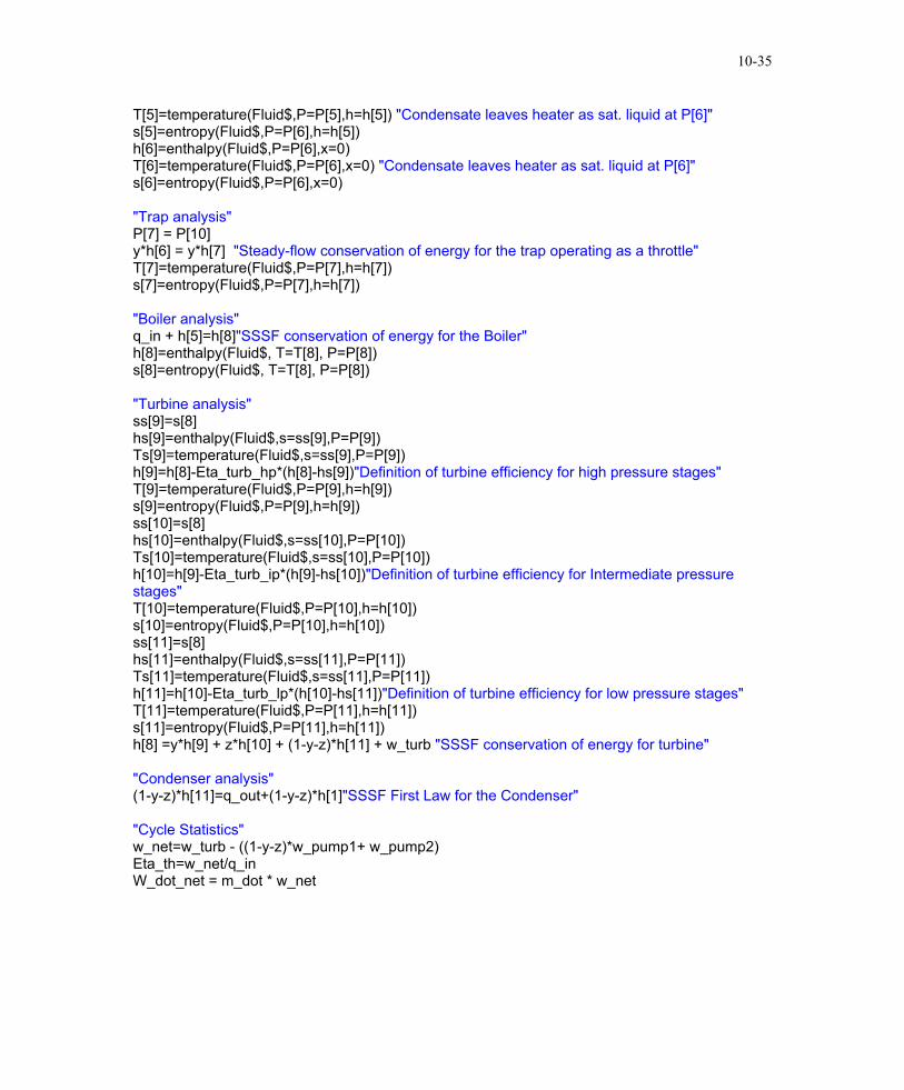
T[5]=temperature(Fluid$,P=P[5],h=h[5]) "Condensate leaves heater as sat. liquid at P[6]" s[5]=entropy(Fluid$,P=P[6],h=h[5]) h[6]=enthalpy(Fluid$,P=P[6],x=0) T[6]=temperature(Fluid$,P=P[6],x=0) "Condensate leaves heater as sat. liquid at P[6]" s[6]=entropy(Fluid$,P=P[6],x=0) "Trap analysis" P[7] = P[10] y*h[6] = y*h[7] "Steady-flow conservation of energy for the trap operating as a throttle" T[7]=temperature(Fluid$,P=P[7],h=h[7]) s[7]=entropy(Fluid$,P=P[7],h=h[7]) "Boiler analysis" q_in + h[5]=h[8]"SSSF conservation of energy for the Boiler" h[8]=enthalpy(Fluid$, T=T[8], P=P[8]) s[8]=entropy(Fluid$, T=T[8], P=P[8]) "Turbine analysis" ss[9]=s[8] hs[9]=enthalpy(Fluid$,s=ss[9],P=P[9]) Ts[9]=temperature(Fluid$,s=ss[9],P=P[9]) h[9]=h[8]-Eta_turb_hp*(h[8]-hs[9])"Definition of turbine efficiency for high pressure stages" T[9]=temperature(Fluid$,P=P[9],h=h[9]) s[9]=entropy(Fluid$,P=P[9],h=h[9]) ss[10]=s[8] hs[10]=enthalpy(Fluid$,s=ss[10],P=P[10]) Ts[10]=temperature(Fluid$,s=ss[10],P=P[10]) h[10]=h[9]-Eta_turb_ip*(h[9]-hs[10])"Definition of turbine efficiency for Intermediate pressure stages" T[10]=temperature(Fluid$,P=P[10],h=h[10]) s[10]=entropy(Fluid$,P=P[10],h=h[10]) ss[11]=s[8] hs[11]=enthalpy(Fluid$,s=ss[11],P=P[11]) Ts[11]=temperature(Fluid$,s=ss[11],P=P[11]) h[11]=h[10]-Eta_turb_lp*(h[10]-hs[11])"Definition of turbine efficiency for low pressure stages" T[11]=temperature(Fluid$,P=P[11],h=h[11]) s[11]=entropy(Fluid$,P=P[11],h=h[11]) h[8] =y*h[9] + z*h[10] + (1-y-z)*h[11] + w_turb "SSSF conservation of energy for turbine" "Condenser analysis" (1-y-z)*h[11]=q_out+(1-y-z)*h[1]"SSSF First Law for the Condenser" "Cycle Statistics" w_net=w_turb - ((1-y-z)*w_pump1+ w_pump2) Eta_th=w_net/q_in W_dot_net = m_dot * w_net

PROPRIETARY MATERIAL. © 2006 The McGraw-Hill Companies, Inc. Limited distribution permitted only to teachers and educators for course preparation. If you are a student using this Manual, you are using it without permission.

10-36

ηturb ηturb ηth m [kg/s] 0.7 0.7 0.3916 231.6

0.75 0.75 0.4045 224.3 0.8 0.8 0.4161 218

0.85 0.85 0.4267 212.6 0.9 0.9 0.4363 207.9

0.95 0.95 0.4452 203.8 1 1 0.4535 200.1

0.7 0.75 0.8 0.85 0.9 0.95 1

0.39

0.4

0.41

0.42

0.43

0.44

0.45

0.46

200

205

210

215

220

225

230

235

ηturb

ηth

m [kg/s]

ηturb =ηpump

0 2 4 6 8 10 120

100

200

300

400

500

600

s [kJ/kg-K]

T[C] 12500 kPa

800 kPa

300 kPa

10 kPa

Steam

1,2

3,4

5,6

7

8

910

11

PROPRIETARY MATERIAL. © 2006 The McGraw-Hill Companies, Inc. Limited distribution permitted only to teachers and educators for course preparation. If you are a student using this Manual, you are using it without permission.

10-37

10-49 A steam power plant operates on an ideal reheat-regenerative Rankine cycle with an open feedwater heater. The mass flow rate of steam through the boiler and the thermal efficiency of the cycle are to be determined. Assumptions 1 Steady operating conditions exist. 2 Kinetic and potential energy changes are negligible. Analysis (a) From the steam tables (Tables A-4, A-5, and A-6),

( ) ( )( )

kJ/kg 61.19280.081.191kJ/kg 0.80

mkPa 1kJ 1

kPa 10800/kgm 0.00101

/kgm 00101.0

kJ/kg 81.191

in,12

33

121in,

3kPa 10 @1

kPa 10 @1

=+=+==

⋅−=−=

==

==

pI

pI

f

f

whh

PPw

hh

v

vv

T

( ) ( )( )

( )( ) kJ/kg 7.24941.23929627.081.191

9627.04996.7

6492.08692.7kPa 10

KkJ/kg 8692.7kJ/kg 3.3481

C500MPa 8.0

kJ/kg 1.2812MPa 8.0

KkJ/kg 7585.6kJ/kg 0.3502

C550MPa 10

kJ/kg 12.73126.1087.720kJ/kg 10.26

mkPa 1kJ 1

kPa 80010,000/kgm 0.001115

/kgm 001115.0

kJ/kg 87.720

liquidsat.MPa 8.0

88

88

78

8

7

7

7

7

656

6

5

5

5

5

in,34

33

343in,

3MPa 8.0 @3

MPa 8.0 @33

=+=+=

=−

=−

=

==

⋅==

°==

=

==

⋅==

°==

=+=+==

⋅−=−=

==

==

=

fgf

fg

f

pII

pII

f

f

hxhh

sss

xss

P

sh

TP

hss

P

sh

TP

whh

PPw

hhP

v

vv

10 MPa

1 - y

63

4

y

10 kPa

0.8 MPa 7

5

8

2

1s

6

1-y 7

6

P II P I

Openfwh

Condenser

BoilerTurbine

4

3 2

1

8

5

y

The fraction of steam extracted is determined from the steady-flow energy balance equation applied to the feedwater heaters. Noting that Q , 0∆pe∆ke ≅≅≅≅W&&

( ) ( 326332266

outin(steady) 0

systemoutin

11

0

hhyyhhmhmhmhmhm

EEEEE

eeii =−+→=+→=

=→=∆=−

∑∑ &&&&&

&&&&&

)where y is the fraction of steam extracted from the turbine ( = & / &m m6 3 ). Solving for y,

2017.061.1921.281261.19287.720

26

23 =−−

=−−

=hhhh

y

Then, ( ) ( )( ) ( ) ( )( )( )( ) ( )( )

kJ/kg 6.14665.18381.3305kJ/kg 5.183881.1917.24942017.011

kJ/kg 1.33051.28123.34812017.0112.7310.35021

outinnet

18out

6745in

=−=−==−−=−−=

=−−+−=−−+−=

qqwhhyq

hhyhhq

and kg/s 54.5===kJ/kg 1466.1kJ/s 80,000

net

net

wW

m&

&

(b) 44.4%===kJ/kg 3305.1kJ/kg 1466.1

in

netth q

PROPRIETARY MATERIAL. © 2006 The McGraw-Hill Companies, Inc. Limited distribution permitted only to teachers and educators for course preparation. If you are a student using this Manual, you are using it without permission.

10-38

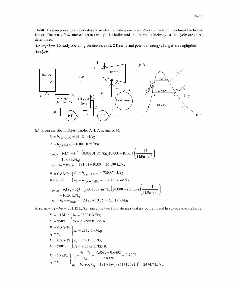
10-50 A steam power plant operates on an ideal reheat-regenerative Rankine cycle with a closed feedwater heater. The mass flow rate of steam through the boiler and the thermal efficiency of the cycle are to be determined. Assumptions 1 Steady operating conditions exist. 2 Kinetic and potential energy changes are negligible. Analysis

9

10

Mixing chamber

1-y

7 y

P II P I

Closed fwh

Condenser

Boiler Turbine

4

3 2

1

8

5

6

T

10 MPa

1 - y

6

3

410

9y

10 kPa

0.8 MPa 7

5

8

2

1

s (a) From the steam tables (Tables A-4, A-5, and A-6),

( ) ( )( )

( ) ( )( )

kJ/kg 13.73126.1087.720kJ/kg 10.26

mkPa 1kJ 1kPa 80010,000/kgm 0.001115

/kgm 001115.0

kJ/kg 87.720

liquidsat.MPa 8.0

kJ/kg 90.20109.1081.191kJ/kg 10.09

mkPa 1kJ 1kPa 1010,000/kgm 0.00101

/kgm 00101.0

kJ/kg 81.191

in,34

33

343in,

3MP 8.0 @3

MPa 8.0 @33

in,12

33

121in,

3kPa 10 @1

kPa 10 @1

=+=+==

⋅−=−=

==

==

=

=+=+==

⋅−=−=

==

==

pII

pII

af

f

pI

pI

f

f

whh

PPw

hhP

whh

PPw

hh

v

vv

v

vv

Also, h4 = h9 = h10 = 731.12 kJ/kg since the two fluid streams that are being mixed have the same enthalpy.

( )( ) kJ/kg 7.24941.23929627.081.191

9627.04996.7

6492.08692.7kPa 10

KkJ/kg 8692.7kJ/kg 3.3481

C500MPa 8.0

kJ/kg 7.2812MPa 8.0

KkJ/kg 7585.6kJ/kg 0.3502

C550MPa 10

88

88

78

8

7

7

7

7

656

6

5

5

5

5

=+=+=

=−

=−

=

==

⋅==

°==

=

==

⋅==

°==

fgf

fg

f

hxhh

sss

x

ssP

sh

TP

hss

P

sh

TP

PROPRIETARY MATERIAL. © 2006 The McGraw-Hill Companies, Inc. Limited distribution permitted only to teachers and educators for course preparation. If you are a student using this Manual, you are using it without permission.

10-39

The fraction of steam extracted is determined from the steady-flow energy balance equation applied to the feedwater heaters. Noting that Q , 0∆peke ≅≅∆≅≅W&&

( ) ( ) ( )( ) ( 3629363292

outin

(steady) 0systemoutin

1

0

hhyhhyhhmhhmhmhm

EE

EEE

eeii −=−−→−=−→=

=

=∆=−

∑∑ &&&&

&&

&&&

)

where y is the fraction of steam extracted from the turbine ( = & / &m m3 4 ). Solving for y,

( ) ( ) 2019.090.20113.73187.7207.2812

90.20113.731

2936

29 =−+−

−=

−+−−

=hhhh

hhy

Then,

( ) ( )( ) ( ) ( )( )( )( ) ( )( )

kJ/kg 6.14668.18375.3304kJ/kg 9.183781.1917.24942019.011

kJ/kg 5.33047.28123.34812019.0113.7310.35021

outinnet

18out

6745in

=−=−==−−=−−=

=−−+−=−−+−=

qqwhhyq

hhyhhq

and

kg/s 54.5===kJ/kg 1467.1kJ/s 80,000

net

net

wW

m&

&

(b) 44.4%=−=−=kJ/kg 3304.5kJ/kg 1837.8

11in

outth q

PROPRIETARY MATERIAL. © 2006 The McGraw-Hill Companies, Inc. Limited distribution permitted only to teachers and educators for course preparation. If you are a student using this Manual, you are using it without permission.

10-40

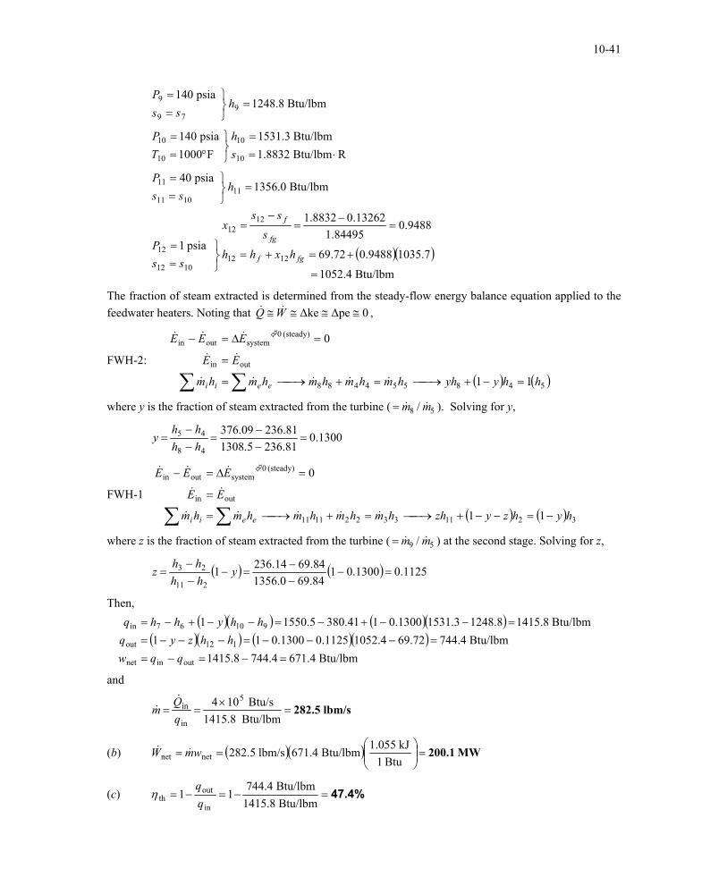
10-51E A steam power plant operates on an ideal reheat-regenerative Rankine cycle with one reheater and two open feedwater heaters. The mass flow rate of steam through the boiler, the net power output of the plant, and the thermal efficiency of the cycle are to be determined. Assumptions 1 Steady operating conditions exist. 2 Kinetic and potential energy changes are negligible. Analysis

High-P Turbine

5 P III

1-y-z 1211

z

10

4

Open fwh II

1-y

y

P II P I

Open fwh I

Condenser

Boiler Low-P Turbine

6

3 2

1

8

7

9

T

9

10z

1500 8 1 - y 5

6

3

y 4 250 psia

1 psia

40 psia 140 psia

1 - y - z

11

7

12

2

1

s (a) From the steam tables (Tables A-4E, A-5E, and A-6E),

( )

( )( )

Btu/lbm 84.6912.072.69Btu/lbm 0.12

ftpsia 5.4039Btu 1

psia 140/lbmft 0.01614

/lbmft 01614.0

Btu/lbm 72.69

in,12

33

121in,

3psia 1 @1

psia 1 @1

=+=+==

⋅−=

−=

==

==

pI

pI

f

f

whh

PPw

hh

v

vv

( )( )( )

( )( )( )

Btu/lbm 41.38031.409.376Btu/lbm 4.31

ftpsia 5.4039Btu 1

psia 2501500/lbmft 0.01865

/lbmft 01865.0Btu/lbm 09.376

liquid sat.psia 250

Btu/lbm 81.23667.014.236

Btu/lbm 0.67ftpsia 5.4039

Btu 1psia 40250/lbmft 0.01715

/lbmft 01715.0Btu/lbm 14.236

liquid sat.psia 40

in,56

33

565in,

3psia 250 @5

psia 250 @55

i,34

33

343in,

3psia 40 @3

psia 40 @33

=+=+==

⋅−=

−=

==

==

=

=+=+=

=

⋅−=

−=

==

==

=

pIII

pIII

f

f

npII

pII

f

f

whh

PPw

hhP

whh

PPw

hhP

v

vv

v

vv

Btu/lbm 5.1308psia 250

RBtu/lbm 6402.1Btu/lbm 5.1550

F1100psia 1500

878

8

7

7

7

7

=

==

⋅==

°==

hss

P

sh

TP

PROPRIETARY MATERIAL. © 2006 The McGraw-Hill Companies, Inc. Limited distribution permitted only to teachers and educators for course preparation. If you are a student using this Manual, you are using it without permission.

10-41

( )(Btu/lbm 4.1052

7.10359488.072.69

9488.084495.1

13262.08832.1

psia 1

Btu/lbm 0.1356psia 40

RBtu/lbm 8832.1Btu/lbm 3.1531

F1000psia 140

Btu/lbm 8.1248psia 140

1212

1212

1012

12

111011

11

10

10

10

10

979

9

=

+=+=

=−

=−

=

==

=

==

⋅==

°==

=

==

fgf

fg

f

hxhh

sss

x

ssP

hss

P

sh

TP

hss

P

)

)

The fraction of steam extracted is determined from the steady-flow energy balance equation applied to the feedwater heaters. Noting that Q , 0∆pe∆ke ≅≅≅≅W&&

FWH-2:

( ) ( 548554488

outin

(steady) 0systemoutin

11

0

hhyyhhmhmhmhmhm

EE

EEE

eeii =−+→=+→=

=

=∆=−

∑∑ &&&&&

&&

&&&

where y is the fraction of steam extracted from the turbine ( = & / &m m8 5 ). Solving for y,

1300.081.2365.130881.23609.376

48

45 =−−

=−−

=hhhh

y

FWH-1

( ) ( 321133221111

outin

(steady) 0systemoutin

11

0

hyhzyzhhmhmhmhmhm

EE

EEE

eeii −=−−+→=+→=

=

=∆=−

∑∑ &&&&&

&&

&&&

)

where z is the fraction of steam extracted from the turbine ( = & / &m m9 5 ) at the second stage. Solving for z,

( ) ( ) 1125.01300.0184.690.135684.6914.2361

211

23 =−−−

=−−−

= yhhhh

z

Then,

( )( ) ( )( )

( )( ) ( )( )Btu/lbm 4.6714.7448.1415

Btu/lbm 744.469.721052.41125.01300.011Btu/lbm 8.14158.12483.15311300.0141.3805.15501

outinnet

112out

91067in

=−=−==−−−=−−−=

=−−+−=−−+−=

qqwhhzyq

hhyhhq

and

lbm/s 282.5=×

==Btu/lbm 1415.8

Btu/s 104 5

in

in

qQ

m&

&

(b) ( )( ) MW 200.1=

==

Btu 1kJ 1.055

Btu/lbm 671.4lbm/s 282.5netnet wmW &&

(c) 47.4%=−=−=Btu/lbm 1415.8Btu/lbm 744.4

11in

outth q

PROPRIETARY MATERIAL. © 2006 The McGraw-Hill Companies, Inc. Limited distribution permitted only to teachers and educators for course preparation. If you are a student using this Manual, you are using it without permission.

10-42

10-52 A steam power plant that operates on an ideal regenerative Rankine cycle with a closed feedwater heater is considered. The temperature of the steam at the inlet of the closed feedwater heater, the mass flow rate of the steam extracted from the turbine for the closed feedwater heater, the net power output, and the thermal efficiency are to be determined. Assumptions 1 Steady operating conditions exist. 2 Kinetic and potential energy changes are negligible. Analysis (a) From the steam tables (Tables A-4, A-5, and A-6),

( )

kJ/kg 85.26543.1442.251

kJ/kg .431488.0/)kPa 2012,500)(/kgm 0.001017(

/

/kgm 001017.0

kJ/kg 42.251

in,12

3121in,

3kPa 20 @1

kPa 20 @1

=+=+=

=−=

−=

==

==

pI

ppI

f

f

whh

PPw

hh

ηv

vvLow-P turbine

910

11

MixingCham.

1-y7

y

PII PI

Closed fwh Cond.

Boiler

High-P turbine

4

3 2

1

8

5

6

/kgm 001127.0

kJ/kg 51.762

liquid sat.MPa 1

3MPa 1 @3

MPa 1 @33

==

==

=

f

fhhPvv

( )

kJ/kg 25.77773.1451.762kJ/kg 73.14

88.0/)kPa 001012,500)(/kgm 001127.0(

/

in,311

3

3113in,

=+=+==

−=

−=

pII

ppII

whh

PPw ηv

Also, h4 = h10 = h11 = 777.25 kJ/kg since the two fluid streams which are being mixed have the same enthalpy.

( )( )( ) kJ/kg 5.32206.31855.347688.05.3476

kJ/kg 6.3185MPa 5

KkJ/kg 6317.6kJ/kg 5.3476

C550MPa 5.12

655665

65

656

6

5

5

5

5

=−−=−−=→

−−

=

=

==

⋅==

°==

sTs

T

s

hhhhhhhh

hss

P

sh

TP

ηη

( )( )( )

C328°=

==

=−−=−−=→

−−

=

=

==

⋅==

°==

88

8

877887

87

878

8

7

7

7

7

kJ/kg 1.3111MPa 1

kJ/kg 1.31111.30519.355088.09.3550

kJ/kg 1.3051MPa 1

KkJ/kg 1238.7kJ/kg 9.3550

C550MPa 5

ThP

hhhhhhhh

hss

P

sh

TP

sTs

T

s

ηη

PROPRIETARY MATERIAL. © 2006 The McGraw-Hill Companies, Inc. Limited distribution permitted only to teachers and educators for course preparation. If you are a student using this Manual, you are using it without permission.

10-43

( )( )( ) kJ/kg 2.24929.23479.355088.09.3550

kJ/kg 9.2347kPa 20

977997

97

979

9

=−−=−−=→

−−

=

=

==

sTs

T

s

hhhhhhhh

hss

P

ηη

The fraction of steam extracted from the low pressure turbine for closed feedwater heater is determined from the steady-flow energy balance equation applied to the feedwater heater. Noting that

, & &Q W ke pe≅ ≅ ≅ ≅∆ ∆ 0

( )( ) ( )1788.0)51.7621.3111()85.26525.777)(1(

1 38210

=→−=−−

−=−−

yyy

hhyhhy

The corresponding mass flow rate is kg/s 4.29=== kg/s) 24)(1788.0(58 mym &&

(c) Then,

( )( ) ( )( ) kJ/kg 1.184042.2512.24921788.011kJ/kg 7.30295.32209.355025.7775.3476

19out

6745in

=−−=−−==−+−=−+−=

hhyqhhhhq

and

kW 28,550=−=−= kJ/kg)1.18407.3029)(kg/s 24()( outinnet qqmW &&

(b) The thermal efficiency is determined from

39.3%==−=−= 393.0kJ/kg 3029.7kJ/kg 1840.1

11in

outth q

PROPRIETARY MATERIAL. © 2006 The McGraw-Hill Companies, Inc. Limited distribution permitted only to teachers and educators for course preparation. If you are a student using this Manual, you are using it without permission.

10-44

Second-Law Analysis of Vapor Power Cycles 10-53C In the simple ideal Rankine cycle, irreversibilities occur during heat addition and heat rejection processes in the boiler and the condenser, respectively, and both are due to temperature difference. Therefore, the irreversibilities can be decreased and thus the 2nd law efficiency can be increased by minimizing the temperature differences during heat transfer in the boiler and the condenser. One way of doing that is regeneration. 10-54 The exergy destructions associated with each of the processes of the Rankine cycle described in Prob. 10-15 are to be determined for the specified source and sink temperatures. Assumptions 1 Steady operating conditions exist. 2 Kinetic and potential energy changes are negligible. Analysis From Problem 10-15,

kJ/kg 8.1931kJ/kg 72.2650

KkJ/kg 5412.6

KkJ/kg 0912.1

out

43

kPa 50 @21

==

⋅==

⋅===

qq

ss

sss

in

f

Processes 1-2 and 3-4 are isentropic. Thus, i12 = 0 and i34 = 0. Also,

( )

( ) kJ/kg 351.3

kJ/kg 1068

=

+−=

+−=

=

−+−=

+−=

K 290kJ/kg 1931.85412.60912.1K 290

K 1500kJ/kg 2650.80912.15412.6K 290

41,41041destroyed,

23,23023destroyed,

R

R

R

R

Tq

ssTx

Tq

ssTx

10-55 The exergy destructions associated with each of the processes of the Rankine cycle described in Prob. 10-16 are to be determined for the specified source and sink temperatures. Assumptions 1 Steady operating conditions exist. 2 Kinetic and potential energy changes are negligible. Analysis From Problem 10-16,

kJ/kg 9.1897kJ/kg 2.3173

KkJ/kg 5995.6

KkJ/kg 6492.0

out

in

43

kPa10@21

==

⋅==

⋅===

qq

ss

sss f

Processes 1-2 and 3-4 are isentropic. Thus, i12 = 0 and i34 = 0. Also,

( )

( ) kJ/kg 172.3

kJ/kg 1112.1

=

+−=

+−=

=

−+−=

+−=

K 290kJ/kg 1897.9

5995.66492.0K 290

K 1500kJ/kg 3173.2

6492.05995.6K 290

41,41041destroyed,

23,23023destroyed,

R

R

R

R

Tq

ssTx

Tq

ssTx

PROPRIETARY MATERIAL. © 2006 The McGraw-Hill Companies, Inc. Limited distribution permitted only to teachers and educators for course preparation. If you are a student using this Manual, you are using it without permission.

10-45

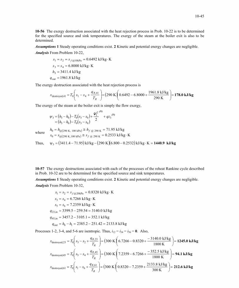
10-56 The exergy destruction associated with the heat rejection process in Prob. 10-22 is to be determined for the specified source and sink temperatures. The exergy of the steam at the boiler exit is also to be determined. Assumptions 1 Steady operating conditions exist. 2 Kinetic and potential energy changes are negligible. Analysis From Problem 10-22,

kJ/kg 8.1961kJ/kg 4.3411

KkJ/kg 8000.6

KkJ/kg 6492.0

out

3

43

kPa10@21

==

⋅==

⋅===

qh

ss

sss f

The exergy destruction associated with the heat rejection process is

( ) kJ/kg 178.0=

+−=

+−=

K 290kJ/kg 1961.8

8000.66492.0K 29041,41041destroyed,

R

R

Tq

ssTx

The exergy of the steam at the boiler exit is simply the flow exergy,

( ) ( )( ) ( )03003

03

023

030033 2ssThhqzssThh

−−−=++−−−=

where ( )( ) KkJ/kg 2533.0

kJ/kg 95.71

K 290 @ kPa 100,K 290@0

K 290 @ kPa 100 ,K 290@0

⋅=≅==≅=

f

f

ssshhh

Thus, ( ) ( )( ) kJ/kg 1440.9=⋅−−−=ψ KkJ/kg 2532.0800.6K 290kJ/kg 95.714.34113

10-57 The exergy destructions associated with each of the processes of the reheat Rankine cycle described in Prob. 10-32 are to be determined for the specified source and sink temperatures. Assumptions 1 Steady operating conditions exist. 2 Kinetic and potential energy changes are negligible. Analysis From Problem 10-32,

kJ/kg 8.213342.2512.2385

kJ/kg 1.3521.31052.3457

kJ/kg 0.314054.2595.3399KkJ/kg 2359.7KkJ/kg 7266.6

KkJ/kg 8320.0

16out

in,45

in,23

65

43

kPa20@21

=−=−=

=−=

=−=⋅==⋅==

⋅===

hhq

q

qssss

sss f

Processes 1-2, 3-4, and 5-6 are isentropic. Thus, i12 = i34 = i56 = 0. Also,

( )

( )

( ) kJ/kg 212.6

kJ/kg 94.1

kJ/kg 1245.0

=

+−=

+−=

=

−+−=

+−=

=

+−=

+−=

K 300kJ/kg 2133.82359.78320.0K 300

K 1800kJ/kg 352.57266.62359.7K 300

K 1800kJ/kg 3140.08320.07266.6K 300

61,61061destroyed,

45,45045destroyed,

23,23023destroyed,

R

R

R

R

R

R

Tq

ssTx

Tq

ssTx

Tq

ssTx

PROPRIETARY MATERIAL. © 2006 The McGraw-Hill Companies, Inc. Limited distribution permitted only to teachers and educators for course preparation. If you are a student using this Manual, you are using it without permission.

10-46

10-58 EES Problem 10-57 is reconsidered. The problem is to be solved by the diagram window data entry feature of EES by including the effects of the turbine and pump efficiencies. Also, the T-s diagram is to be plotted. Analysis The problem is solved using EES, and the solution is given below. function x6$(x6) "this function returns a string to indicate the state of steam at point 6" x6$='' if (x6>1) then x6$='(superheated)' if (x6<0) then x6$='(subcooled)' end "Input Data - from diagram window" {P[6] = 20 [kPa] P[3] = 8000 [kPa] T[3] = 500 [C] P[4] = 3000 [kPa] T[5] = 500 [C] Eta_t = 100/100 "Turbine isentropic efficiency" Eta_p = 100/100 "Pump isentropic efficiency"} "Data for the irreversibility calculations:" T_o = 300 [K] T_R_L = 300 [K] T_R_H = 1800 [K] "Pump analysis" Fluid$='Steam_IAPWS' P[1] = P[6] P[2]=P[3] x[1]=0 "Sat'd liquid" h[1]=enthalpy(Fluid$,P=P[1],x=x[1]) v[1]=volume(Fluid$,P=P[1],x=x[1]) s[1]=entropy(Fluid$,P=P[1],x=x[1]) T[1]=temperature(Fluid$,P=P[1],x=x[1]) W_p_s=v[1]*(P[2]-P[1])"SSSF isentropic pump work assuming constant specific volume" W_p=W_p_s/Eta_p h[2]=h[1]+W_p "SSSF First Law for the pump" v[2]=volume(Fluid$,P=P[2],h=h[2]) s[2]=entropy(Fluid$,P=P[2],h=h[2]) T[2]=temperature(Fluid$,P=P[2],h=h[2]) "High Pressure Turbine analysis" h[3]=enthalpy(Fluid$,T=T[3],P=P[3]) s[3]=entropy(Fluid$,T=T[3],P=P[3]) v[3]=volume(Fluid$,T=T[3],P=P[3]) s_s[4]=s[3] hs[4]=enthalpy(Fluid$,s=s_s[4],P=P[4]) Ts[4]=temperature(Fluid$,s=s_s[4],P=P[4]) Eta_t=(h[3]-h[4])/(h[3]-hs[4])"Definition of turbine efficiency" T[4]=temperature(Fluid$,P=P[4],h=h[4]) s[4]=entropy(Fluid$,T=T[4],P=P[4]) v[4]=volume(Fluid$,s=s[4],P=P[4]) h[3] =W_t_hp+h[4]"SSSF First Law for the high pressure turbine" "Low Pressure Turbine analysis" P[5]=P[4] s[5]=entropy(Fluid$,T=T[5],P=P[5]) h[5]=enthalpy(Fluid$,T=T[5],P=P[5]) s_s[6]=s[5] hs[6]=enthalpy(Fluid$,s=s_s[6],P=P[6]) Ts[6]=temperature(Fluid$,s=s_s[6],P=P[6]) vs[6]=volume(Fluid$,s=s_s[6],P=P[6]) Eta_t=(h[5]-h[6])/(h[5]-hs[6])"Definition of turbine efficiency" h[5]=W_t_lp+h[6]"SSSF First Law for the low pressure turbine" x[6]=QUALITY(Fluid$,h=h[6],P=P[6])

PROPRIETARY MATERIAL. © 2006 The McGraw-Hill Companies, Inc. Limited distribution permitted only to teachers and educators for course preparation. If you are a student using this Manual, you are using it without permission.

10-47

"Boiler analysis" Q_in + h[2]+h[4]=h[3]+h[5]"SSSF First Law for the Boiler" "Condenser analysis" h[6]=Q_out+h[1]"SSSF First Law for the Condenser" T[6]=temperature(Fluid$,h=h[6],P=P[6]) s[6]=entropy(Fluid$,h=h[6],P=P[6]) x6s$=x6$(x[6]) "Cycle Statistics" W_net=W_t_hp+W_t_lp-W_p Eff=W_net/Q_in "The irreversibilities (or exergy destruction) for each of the processes are:" q_R_23 = - (h[3] - h[2]) "Heat transfer for the high temperature reservoir to process 2-3" i_23 = T_o*(s[3] -s[2] + q_R_23/T_R_H) q_R_45 = - (h[5] - h[4]) "Heat transfer for the high temperature reservoir to process 4-5" i_45 = T_o*(s[5] -s[4] + q_R_45/T_R_H) q_R_61 = (h[6] - h[1]) "Heat transfer to the low temperature reservoir in process 6-1" i_61 = T_o*(s[1] -s[6] + q_R_61/T_R_L) i_34 = T_o*(s[4] -s[3]) i_56 = T_o*(s[6] -s[5]) i_12 = T_o*(s[2] -s[1])

0 .0 1 .1 2 .2 3 .3 4 .4 5 .5 6 .6 7 .7 8.8 9 .9 11 .00

100

200

300

400

500

600

700

s [kJ /kg -K ]

T [C

]

8000 kP a

300 0 kP a

20 kP a

3

4

5

6

Id ea l R an k in e cyc le w ith reh eat

1 ,2

SOLUTION Eff=0.389 Eta_p=1 Eta_t=1 Fluid$='Steam_IAPWS' h[1]=251.4 [kJ/kg] h[2]=259.5 [kJ/kg] h[3]=3400 [kJ/kg] h[4]=3105 [kJ/kg] h[5]=3457 [kJ/kg] h[6]=2385 [kJ/kg] hs[4]=3105 [kJ/kg] hs[6]=2385 [kJ/kg] i_12=0.012 [kJ/kg] i_23=1245.038 [kJ/kg] i_34=-0.000 [kJ/kg] i_45=94.028 [kJ/kg] i_56=0.000 [kJ/kg] i_61=212.659 [kJ/kg] P[1]=20 [kPa] P[2]=8000 [kPa]

P[3]=8000 [kPa] P[4]=3000 [kPa] P[5]=3000 [kPa] P[6]=20 [kPa] Q_in=3493 [kJ/kg] Q_out=2134 [kJ/kg] q_R_23=-3140 [kJ/kg] q_R_45=-352.5 [kJ/kg] q_R_61=2134 [kJ/kg] s[1]=0.832 [kJ/kg-K] s[2]=0.8321 [kJ/kg-K] s[3]=6.727 [kJ/kg-K] s[4]=6.727 [kJ/kg-K] s[5]=7.236 [kJ/kg-K] s[6]=7.236 [kJ/kg-K] s_s[4]=6.727 [kJ/kg-K] s_s[6]=7.236 [kJ/kg-K] T[1]=60.06 [C] T[2]=60.4 [C] T[3]=500 [C]

T[4]=345.2 [C] T[5]=500 [C] T[6]=60.06 [C] Ts[4]=345.2 [C] Ts[6]=60.06 [C] T_o=300 [K] T_R_H=1800 [K] T_R_L=300 [K] v[1]=0.001017 [m^3/kg] v[2]=0.001014 [m^3/kg] v[3]=0.04177 [m^3/kg] v[4]=0.08968 [m^3/kg] vs[6]=6.922 [m^3/kg] W_net=1359 [kJ/kg] W_p=8.117 [kJ/kg] W_p_s=8.117 [kJ/kg] W_t_hp=294.8 [kJ/kg] W_t_lp=1072 [kJ/kg] x6s$='' x[1]=0

PROPRIETARY MATERIAL. © 2006 The McGraw-Hill Companies, Inc. Limited distribution permitted only to teachers and educators for course preparation. If you are a student using this Manual, you are using it without permission.

10-31

x[6]=0.9051

PROPRIETARY MATERIAL. © 2006 The McGraw-Hill Companies, Inc. Limited distribution permitted only to teachers and educators for course preparation. If you are a student using this Manual, you are using it without permission.

10-48

10-59 The exergy destruction associated with the heat addition process and the expansion process in Prob. 10-34 are to be determined for the specified source and sink temperatures. The exergy of the steam at the boiler exit is also to be determined. Assumptions 1 Steady operating conditions exist. 2 Kinetic and potential energy changes are negligible. Analysis From Problem 10-34,

( )

( )

kJ/kg 8.3749kJ/kg 1.3375

kJ/kg 8.2664 ,kPa 10 KkJ/kg 3870.8KkJ/kg 7642.7

kJ/kg 0.2902 ,MPa 1 KkJ/kg 8464.6KkJ/kg 5995.6

KkJ/kg 6492.0

in

3

666

5

444

3

kPa 10 @ 21

==

==⋅=⋅=

==⋅=⋅=

⋅===

qh

hPss

hPss

sss f

The exergy destruction associated with the combined pumping and the heat addition processes is

( ) kJ/kg 5.1289K 1600kJ/kg 3749.8

8464.67642.76492.05995.6K 285

15,45130destroyed

=

−+−+−=

+−+−=

R

R

Tq

ssssTx

The exergy destruction associated with the pumping process is

Thus, kJ/kg 1289=−=−=

=−=∆−=−≅

5.05.1289

kJ/kg53.009.1062.10

12destroyed,destroyedheating destroyed,

,,,12destroyed,

xxx

Pvwwwx apspap

The exergy destruction associated with the expansion process is

( ) ( )

( )( ) kJ/kg 247.9=⋅−+−=

+−+−=

KkJ/kg7642.73870.85995.68464.6K 285

036,

5634034destroyed,R

R

Tq

ssssTx

The exergy of the steam at the boiler exit is determined from

( ) ( )( ) ( )03003

03

023

030033 2ssThhqz

VssThh

−−−=++−−−=ψ

where

( )( ) KkJ/kg 1806.0

kJ/kg 51.50

K 285 @ kPa 100 K, 285 @ 0

K 285 @ kPa 100 K, 285 @ 0

⋅=≅==≅=

f

f

ssshhh

Thus, ( ) ( )( ) kJ/kg 1495=⋅−−−= KkJ/kg 1806.05995.6K 285kJ/kg 51.501.33753ψ

PROPRIETARY MATERIAL. © 2006 The McGraw-Hill Companies, Inc. Limited distribution permitted only to teachers and educators for course preparation. If you are a student using this Manual, you are using it without permission.

10-49

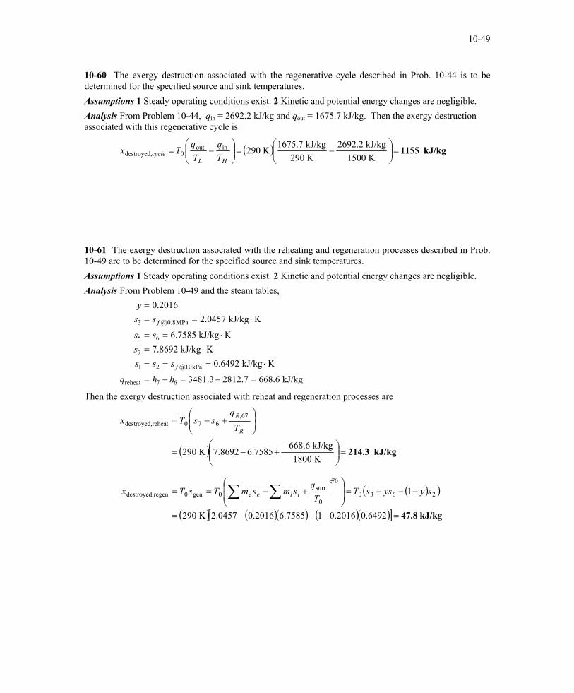
10-60 The exergy destruction associated with the regenerative cycle described in Prob. 10-44 is to be determined for the specified source and sink temperatures. Assumptions 1 Steady operating conditions exist. 2 Kinetic and potential energy changes are negligible. Analysis From Problem 10-44, qin = 2692.2 kJ/kg and qout = 1675.7 kJ/kg. Then the exergy destruction associated with this regenerative cycle is

( ) kJ/kg 1155=

−=

−=

K 1500kJ/kg 2692.2

K 290kJ/kg 1675.7

K 290inout0destroyed,

HLcycle T

qTq

Tx

10-61 The exergy destruction associated with the reheating and regeneration processes described in Prob. 10-49 are to be determined for the specified source and sink temperatures. Assumptions 1 Steady operating conditions exist. 2 Kinetic and potential energy changes are negligible. Analysis From Problem 10-49 and the steam tables,

kJ/kg 6.6687.28123.3481

KkJ/kg 6492.0KkJ/kg 8692.7

KkJ/kg 7585.6

KkJ/kg 0457.22016.0

67reheat

kPa10@21

7

65

MPa8.0@3

=−=−=

⋅===⋅=

⋅==

⋅===

hhq

ssss

ss

ssy

f

f

Then the exergy destruction associated with reheat and regeneration processes are

( )

( )( )

( ) ( )( ) ( )( )[ ] kJ/kg 47.8

kJ/kg 214.3

=−−−=

−−−=

+−==

=

−+−=

+−=

∑∑6492.02016.017585.62016.00457.2K 290

1

K 1800kJ/kg 668.6

7585.68692.7K 290

2630

0

0

surr0gen0regendestroyed,

67,670reheatdestroyed,

syyssTT

qsmsmTsTx

Tq

ssTx

iiee

R

R

PROPRIETARY MATERIAL. © 2006 The McGraw-Hill Companies, Inc. Limited distribution permitted only to teachers and educators for course preparation. If you are a student using this Manual, you are using it without permission.

10-50

10-62 A single-flash geothermal power plant uses hot geothermal water at 230ºC as the heat source. The power output from the turbine, the thermal efficiency of the plant, the exergy of the geothermal liquid at the exit of the flash chamber, and the exergy destructions and exergy efficiencies for the flash chamber, the turbine, and the entire plant are to be determined. Assumptions 1 Steady operating conditions exist. 2 Kinetic and potential energy changes are negligible. Analysis (a) We use properties of water for geothermal water (Tables A-4, A-5, and A-6)

kJ/kg.K 6841.21661.0

kJ/kg 14.990kPa 500

kJ/kg.K 6100.2kJ/kg 14.990

0C230

2

2

12

2

1

1

1

1

==

===

==

=°=

sx

hhP

sh

xT

kg/s 38.19kg/s) 230)(1661.0(

123

=== mxm &&

KkJ/kg 7739.7kJ/kg 3.2464

95.0kPa 10

KkJ/kg 8207.6kJ/kg 1.2748

1kPa 500

4

4

4

4

3

3

3

3

⋅==

==

⋅==

==

sh

xP

sh

xP

KkJ/kg 8604.1

kJ/kg 09.6400

kPa 500

6

6

6

6

⋅==

==

sh

xP

kg/s 81.19119.38230316 =−=−= mmm &&&

2

production well

reinjection well

separator

steam turbine

1

Flash chamber

65

4

3

condenser

The power output from the turbine is

kW 10,842=−=−= kJ/kg)3.24648.1kJ/kg)(274 38.19()( 433T hhmW &&

We use saturated liquid state at the standard temperature for dead state properties

kJ/kg 3672.0kJ/kg 83.104

0C25

0

0

0

0

==

=°=

sh

xT

kW 622,203kJ/kg)83.104.14kJ/kg)(990 230()( 011in =−=−= hhmE &&

5.3%==== 0.0532622,203

842,10

in

outT,th E

W&

(b) The specific exergies at various states are kJ/kg 53.216kJ/kg.K)3672.0K)(2.6100 (298kJ/kg)83.104(990.14)( 010011 =−−−=−−−= ssThhψ

kJ/kg 44.194kJ/kg.K)3672.0K)(2.6841 (298kJ/kg)83.104(990.14)( 020022 =−−−=−−−= ssThhψ

kJ/kg 10.719kJ/kg.K)3672.0K)(6.8207 (298kJ/kg)83.104(2748.1)( 030033 =−−−=−−−= ssThhψ

kJ/kg 05.151kJ/kg.K)3672.0K)(7.7739 (298kJ/kg)83.104(2464.3)( 040044 =−−−=−−−= ssThhψ

kJ/kg 97.89kJ/kg.K)3672.0K)(1.8604 (298kJ/kg)83.104(640.09)( 060066 =−−−=−−−= ssThhψ

The exergy of geothermal water at state 6 is

kW 17,257=== kJ/kg) 7kg/s)(89.9 .81191(666 ψmX &&

PROPRIETARY MATERIAL. © 2006 The McGraw-Hill Companies, Inc. Limited distribution permitted only to teachers and educators for course preparation. If you are a student using this Manual, you are using it without permission.

10-51

(c) Flash chamber:

kW 5080=−=−= kJ/kg)44.19453kg/s)(216. 230()( 211FC dest, ψψmX &&

89.8%==== 0.89853.21644.194

1

2FCII, ψ

ψη

(d) Turbine:

kW 10,854=−=−−= kW 10,842-kJ/kg)05.15110kg/s)(719. 19.38()( T433Tdest, WmX &&& ψψ

50.0%==−

=−

= 0.500)kJ/kg05.15110kg/s)(719. 19.38(

kW 842,10)( 433

TTII, ψψ

ηm

W&

&

(e) Plant:

kW 802,49kJ/kg) 53kg/s)(216. 230(11Plantin, === ψmX &&

kW 38,960=−=−= 842,10802,49TPlantin,Plantdest, WXX &&&

21.8%==== 0.2177kW 802,49kW 842,10

Plantin,

TPlantII, X

W&

Cogeneration 10-63C The utilization factor of a cogeneration plant is the ratio of the energy utilized for a useful purpose to the total energy supplied. It could be unity for a plant that does not produce any power. 10-64C No. A cogeneration plant may involve throttling, friction, and heat transfer through a finite temperature difference, and still have a utilization factor of unity. 10-65C Yes, if the cycle involves no irreversibilities such as throttling, friction, and heat transfer through a finite temperature difference. 10-66C Cogeneration is the production of more than one useful form of energy from the same energy source. Regeneration is the transfer of heat from the working fluid at some stage to the working fluid at some other stage.

PROPRIETARY MATERIAL. © 2006 The McGraw-Hill Companies, Inc. Limited distribution permitted only to teachers and educators for course preparation. If you are a student using this Manual, you are using it without permission.


Recommended