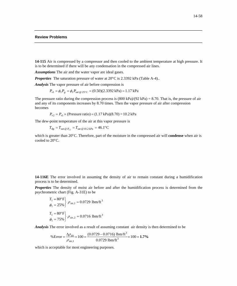
Review Problems 14-115 Air is compressed by a compressor and then cooled to the ambient temperature at high pressure. It is to be determined if there will be any condensation in the compressed air lines. Assumptions The air and the water vapor are ideal gases. Properties The saturation pressure of water at 20°C is 2.3392 kPa (Table A-4).. Analysis The vapor pressure of air before compression is kPa 17.1kPa) 392(0.50)(2.3C25@sat 111 ==== °PPP gv φφ
The pressure ratio during the compression process is (800 kPa)/(92 kPa) = 8.70. That is, the pressure of air and any of its components increases by 8.70 times. Then the vapor pressure of air after compression becomes kPa 10.2=kPa)(8.70) 17.1(ratio) (Pressure12 =×= vv PP
The dew-point temperature of the air at this vapor pressure is C1.46kPa 2.10@sat @sat dp 2
°=== TTTvP
which is greater than 20°C. Therefore, part of the moisture in the compressed air will condense when air is cooled to 20°C. 14-116E The error involved in assuming the density of air to remain constant during a humidification process is to be determined. Properties The density of moist air before and after the humidification process is determined from the psychrometric chart (Fig. A-31E) to be
31,air
1
1 lbm/ft 0729.0%25F80
=⎭⎬⎫
=°=
ρφT
32,air
1
1 lbm/ft 0716.0%75F80
=⎭⎬⎫
=°=
ρφT
Analysis The error involved as a result of assuming constant air density is then determined to be
1.7%=×−
=×∆
= 100lbm/ft 0729.0
lbm/ft )0716.00729.0(100Error% 3
3
air,1
air
ρρ
which is acceptable for most engineering purposes.
14-117 Dry air flows over a water body at constant pressure and temperature until it is saturated. The molar analysis of the saturated air and the density of air before and after the process are to be determined. Assumptions The air and the water vapor are ideal gases. Properties The molar masses of N2, O2, Ar, and H2O are 28.0, 32.0, 39.9 and 18 kg / kmol, respectively (Table A-1). The molar analysis of dry air is given to be 78.1 percent N2, 20.9 percent O2, and 1 percent Ar. The saturation pressure of water at 25°C is 3.1698 kPa (Table A-4). Also, 1 atm = 101.325 kPa. Analysis (a) Noting that the total pressure remains constant at 101.32 kPa during this process, the partial pressure of air becomes kPa 155.981698.3325.101vaporairvaporair =−=−=→+= PPPPPP
Then the molar analysis of the saturated air becomes
0.0097
0.2025
0.7566
0.0313
====
====
====
===
325.101kPa) 155.98(01.0
325.101kPa) 155.98(209.0
325.101kPa) 155.98(781.0
325.1011698.3
airdry dry,ArArAr
airdry dry,OOO
airdry dry,NNN
OHOH
22
2
22
2
2
2
PPy
PP
y
PPy
PP
y
PPy
PP
y
PP
y
Air 1 atm 25°C
Lake
(b) The molar masses of dry and saturated air are
M y Mi idry air kg / kmol= = × + × + × =∑ 0 781 28 0 0 209 32 0 0 01 39 9 29 0. . . . . . .
M y Mi isat. air kg / kmol= = × + × + × + × =∑ 0 7566 28 0 0 2025 32 0 0 0097 39 9 0 0313 18 28 62. . . . . . . .
Then the densities of dry and saturated air are determined from the ideal gas relation to be
( )[ ]( )3kg/m 1.186=
+⋅⋅==
K27325kg/kmol0.29/Km³/kmolkPa8.314kPa325.101
)/( airdry airdry TMR
P
uρ
( )[ ]( )3kg/m 1.170=
+⋅⋅==
K27325kg/kmol62.28/Km³/kmolkPa8.314kPa325.101
)/( airsat air sat. TMR
P
uρ
Discussion We conclude that the density of saturated air is less than that of the dry air, as expected. This is due to the molar mass of water being less than that of dry air.
14-118E The mole fraction of the water vapor at the surface of a lake and the mole fraction of water in the lake are to be determined and compared. Assumptions 1 Both the air and water vapor are ideal gases. 2 Air is weakly soluble in water and thus Henry’s law is applicable. Properties The saturation pressure of water at 60°F is 0.2564 psia (Table A-4E). Henry’s constant for air dissolved in water at 60ºF (289 K) is given in Table 16-2 to be H = 62,000 bar. Analysis The air at the water surface will be saturated. Therefore, the partial pressure of water vapor in the air at the lake surface will simply be the saturation pressure of water at 60°F, psia 2564.0F@60sat vapor == °PP
Assuming both the air and vapor to be ideal gases, the mole fraction of water vapor in the air at the surface of the lake is determined to be Air
13.8 psi 60°F
Lake
percent) 1.86(or 0.0186===psia 8.13
psia 0.2564vaporvapor P
Py
The partial pressure of dry air just above the lake surface is psia 54.132564.08.13vaporairdry =−=−= PPP
Then the mole fraction of air in the water becomes
Discussion The concentration of air in water just below the air-water interface is 1.51 moles per 100,000 moles. The amount of air dissolved in water will decrease with increasing depth. 14-119 The mole fraction of the water vapor at the surface of a lake at a specified temperature is to be determined. Assumptions 1 Both the air and water vapor are ideal gases. 2 Air at the lake surface is saturated. Properties The saturation pressure of water at 18°C is 2.065 kPa (Table A-4). Analysis The air at the water surface will be saturated. Therefore, the partial pressure of water vapor in the air at the lake surface will simply be the saturation pressure of water at 18°C,
Air 100 kPa
18°C
Lake
kPa 065.2C@18sat vapor == °PP
Assuming both the air and vapor to be ideal gases, the partial pressure and mole fraction of dry air in the air at the surface of the lake are determined to be kPa 94.97065.2100vaporairdry =−=−= PPP
97.9%)(or kPa 100kPa 94.97airdry
airdry 0.979===P
Py
Therefore, the mole fraction of dry air is 97.9 percent just above the air-water interface.
14-120E A room is cooled adequately by a 7500 Btu/h air-conditioning unit. If the room is to be cooled by an evaporative cooler, the amount of water that needs to be supplied to the cooler is to be determined. Assumptions 1 The evaporative cooler removes heat at the same rate as the air conditioning unit. 2 Water evaporates at an average temperature of 70°F. Properties The enthalpy of vaporization of water at 70°F is 1053.7 Btu/lbm (Table A-4E). Analysis Noting that 1 lbm of water removes 1053.7 Btu of heat as it evaporates, the amount of water that needs to evaporate to remove heat at a rate of 7500 Btu/h is determined from to be & &Q m hfg= water
lbm/h 7.12===Btu/lbm 1053.7Btu/h 7500
waterfgh
Qm&
&
14-121E The required size of an evaporative cooler in cfm (ft3/min) for an 8-ft high house is determined by multiplying the floor area of the house by 4. An equivalent rule is to be obtained in SI units. Analysis Noting that 1 ft = 0.3048 m and thus 1 ft2 = 0.0929 m2 and 1 ft3 = 0.0283 m3, and noting that a flow rate of 4 ft3/min is required per ft2 of floor area, the required flow rate in SI units per m2 of floor area is determined to
min/m 22.1m 1
min/m 0283.04m 0929.0
min/ft 4ft 1
32
32
32
↔
×↔
↔
Therefore, a flow rate of 1.22 m3/min is required per m2 of floor area. 14-122 A cooling tower with a cooling capacity of 440 kW is claimed to evaporate 15,800 kg of water per day. It is to be determined if this is a reasonable claim. Assumptions 1 Water evaporates at an average temperature of 30°C. 2 The coefficient of performance of the air-conditioning unit is COP = 3. Properties The enthalpy of vaporization of water at 30°C is 2429.8 kJ/kg (Table A-4). Analysis Using the definition of COP, the electric power consumed by the air conditioning unit when running is
&&
.WQ
incooling
COP kW3
kW= = =440 146 7
Then the rate of heat rejected at the cooling tower becomes & & & . .Q Q Winrejected cooling + = + = =440 146 7 586 7 kW
h
Noting that 1 kg of water removes 2429.8 kJ of heat as it evaporates, the amount of water that needs to evaporate to remove heat at a rate of 586.7 kW is determined from to be & &Q m fgrejected water=
In practice, the air-conditioner will run intermittently rather than continuously at the rated power, and thus the water use will be less. Therefore, the claim amount of 15,800 kg per day is reasonable.
14-123E It is estimated that 190,000 barrels of oil would be saved per day if the thermostat setting in residences in summer were raised by 6°F (3.3°C). The amount of money that would be saved per year is to be determined. Assumptions The average cooling season is given to be 120 days, and the cost of oil to be $20/barrel. Analysis The amount of money that would be saved per year is determined directly from
( ,190 000 barrel / day)(120 days / year)($20 / barrel) = $456,000,000 Therefore, the proposed measure will save about half-a-billion dollars a year. 14-124E Wearing heavy long-sleeved sweaters and reducing the thermostat setting 1°F reduces the heating cost of a house by 4 percent at a particular location. The amount of money saved per year by lowering the thermostat setting by 4°F is to be determined. Assumptions The household is willing to wear heavy long-sleeved sweaters in the house, and the annual heating cost is given to be $600 a year. Analysis The amount of money that would be saved per year is determined directly from
($600 / year)(0.04/ F)(4 F)° ° = $96 / year Therefore, the proposed measure will save the homeowner about $100 during a heating season.. 14-125 Shading the condenser can reduce the air-conditioning costs by up to 10 percent. The amount of money shading can save a homeowner per year during its lifetime is to be determined. Assumptions It is given that the annual air-conditioning cost is $500 a year, and the life of the air-conditioning system is 20 years. Analysis The amount of money that would be saved per year is determined directly from
($500 / year)(20 years)(0.10) = $1000 Therefore, the proposed measure will save about $1000 during the lifetime of the system. 14-126 A tank contains saturated air at a specified state. The mass of the dry air, the specific humidity, and the enthalpy of the air are to be determined. Assumptions The air and the water vapor are ideal gases. Analysis (a) The air is saturated, thus the partial pressure of water vapor is equal to the saturation pressure at the given temperature,
kPa 83.931698.397
kPa 1698.3C25@sat
=−=−=
=== °
va
gv
PPP
PPP
3 m3
25°C 97 kPa
Treating air as an ideal gas,
kg 3.29=⋅⋅
==K) K)(298kg/mkPa 287.0(
)m kPa)(3 83.93(3
3
TRPm
a
aa
V
(b) The specific humidity of air is determined from
air dry O/kgH kg 0.0210 2=−
=−
=kPa )1698.3(97kPa) 1698.3)(622.0(622.0
v
v
PPP
ω
(c) The enthalpy of air per unit mass of dry air is determined from air dry kJ/kg 78.6=°°⋅=+≅+= kJ/kg) 546.5(0.0210)(2+C)C)(25kJ/kg 005.1(gpva hTchhh ωω
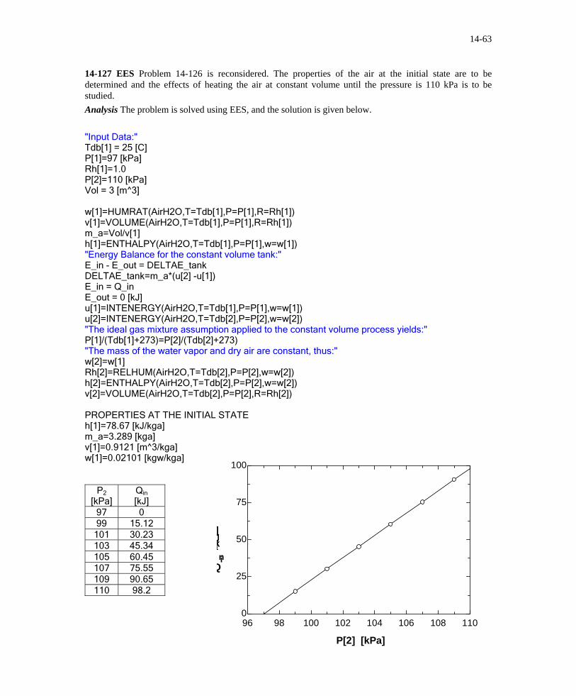
14-127 EES Problem 14-126 is reconsidered. The properties of the air at the initial state are to be determined and the effects of heating the air at constant volume until the pressure is 110 kPa is to be studied. Analysis The problem is solved using EES, and the solution is given below. "Input Data:" Tdb[1] = 25 [C] P[1]=97 [kPa] Rh[1]=1.0 P[2]=110 [kPa] Vol = 3 [m^3] w[1]=HUMRAT(AirH2O,T=Tdb[1],P=P[1],R=Rh[1]) v[1]=VOLUME(AirH2O,T=Tdb[1],P=P[1],R=Rh[1]) m_a=Vol/v[1] h[1]=ENTHALPY(AirH2O,T=Tdb[1],P=P[1],w=w[1]) "Energy Balance for the constant volume tank:" E_in - E_out = DELTAE_tank DELTAE_tank=m_a*(u[2] -u[1]) E_in = Q_in E_out = 0 [kJ] u[1]=INTENERGY(AirH2O,T=Tdb[1],P=P[1],w=w[1]) u[2]=INTENERGY(AirH2O,T=Tdb[2],P=P[2],w=w[2]) "The ideal gas mixture assumption applied to the constant volume process yields:" P[1]/(Tdb[1]+273)=P[2]/(Tdb[2]+273) "The mass of the water vapor and dry air are constant, thus:" w[2]=w[1] Rh[2]=RELHUM(AirH2O,T=Tdb[2],P=P[2],w=w[2]) h[2]=ENTHALPY(AirH2O,T=Tdb[2],P=P[2],w=w[2]) v[2]=VOLUME(AirH2O,T=Tdb[2],P=P[2],R=Rh[2]) PROPERTIES AT THE INITIAL STATE h[1]=78.67 [kJ/kga] m_a=3.289 [kga] v[1]=0.9121 [m^3/kga] w[1]=0.02101 [kgw/kga]
14-128E Air at a specified state and relative humidity flows through a circular duct. The dew-point temperature, the volume flow rate of air, and the mass flow rate of dry air are to be determined. Assumptions The air and the water vapor are ideal gases. Analysis (a) The vapor pressure of air is
Thus the dew-point temperature of the air is (from EES) F41.3°=== psia 128.0@sat @sat dp TTT
vP
(b) The volume flow rate is determined from
/sft 17.45 3=⎟⎟⎠
⎞⎜⎜⎝
⎛ ×===
4)ft 12/8(ft/s) 50(
4
22 ππDVVAV&
(c) To determine the mass flow rate of dry air, we first need to calculate its specific volume,
airdry lbm/ft 95.12
psia 872.14R) R)(520lbm/ftpsia 3704.0(
psia 872.14128.015
33
1
11 =
⋅⋅==
=−=−=
a
a
va
PTR
PPP
v
Thus, lbm/s 1.35===airdry lbm/ft 95.12
s/ft 45.173
3
1
11 v
V&& am
14-129 Air enters a cooling section at a specified pressure, temperature, and relative humidity. The temperature of the air at the exit and the rate of heat transfer are to be determined. Assumptions 1 This is a steady-flow process and thus the mass flow rate of dry air remains constant during the entire process ( . 2 Dry air and water vapor are ideal gases. 3 The kinetic and potential energy changes are negligible.
& & & )m m ma a a1 2= =
Analysis (a) The amount of moisture in the air also remains constant ( )ω ω1 2= as it flows through the cooling section since the process involves no humidification or dehumidification. The total pressure is 97 kPa. The properties of the air at the inlet state are
)(air dry O/kgH kg 0.0110kPa )69.1(97kPa) 69.1(622.0 622.0
airdry kg/m 927.0
kPa 31.95K) K)(308kg/mkPa 287.0(
kPa 31.9569.197
kPa 69.1kPa) 629.5)(3.0(
1111
2211
11
3
3
1
11
111
C35@sat 1111
=°°=+=
==−
=−
=
=
⋅⋅==
=−=−=
==== °
gp
v
v
a
a
va
gv
hTch
PPP
PTR
PPP
PPP
ω
ωω
φφ
v
35°C 30% 6 m3/min 97 kPa
Cooling coils
AIR 1 2
The air at the final state is saturated and the vapor pressure during this process remains constant. Therefore, the exit temperature of the air must be the dew-point temperature, C14.8°=== kPa 69.1@sat @sat dp TTT
vP
(b) The enthalpy of the air at the exit is airdry kJ/kg 78.42kJ/kg) 528.1(0.0110)(2+C)C)(14.8kJ/kg 005.1(2222 =°°⋅=+= gp hTch ω
Also kg/min 47.6airdry kg/m 927.0
s/m 63
3
1
1 ===v
V&& am
Then the rate of heat transfer from the air in the cooling section becomes kJ/min 134=−=−= kJ/kg).7842.44kg/min)(63 47.6()( 21out hhmQ a&
14-130 The outdoor air is first heated and then humidified by hot steam in an air-conditioning system. The rate of heat supply in the heating section and the mass flow rate of the steam required in the humidifying section are to be determined. Assumptions 1 This is a steady-flow process and thus the mass flow rate of dry air remains constant during the entire process ( . 2 Dry air and water vapor are ideal gases. 3 The kinetic and potential energy changes are negligible.
& & & )m m ma a a1 2= =
Properties The amount of moisture in the air also remains constants it flows through the heating section ( )ω ω1 2= , but increases in the humidifying section ( )ω ω3 2> . The inlet and the exit states of the air are completely specified, and the total pressure is 1 atm. The properties of the air at various states are determined from the psychrometric chart (Fig. A-31) to be
airdry /kgm 807.0
)(air dry O/kgH kg 0030.0airdry kJ/kg 7.17
31
221
1
=
===
v
ωωh
10°C 40% 22 m3/min
1 atm
22°C
Heating coils
3
AIR25°C 55%
2 1
h2
1
29 80 0030
== =
..
kJ / kg dry air kg H O / kg dry air2 2ω ω
h3 52 9
0 0109==
..
kJ / kg dry air kg H O / kg dry air3 2ω
Analysis (a) The mass flow rate of dry air is
kg/min 3.27 kg/m 807.0
min/m 223
3
1
1 ===vV&
& am
Then the rate of heat transfer to the air in the heating section becomes
& & ( ) ( . . )Q m h hain kg / min)(29.8 kJ / kg= − = − =2 1 27 3 17 7 330.3 kJ / min
(b) The conservation of mass equation for water in the humidifying section can be expressed as & & & & & ( )m m m m ma w a w a2 2 3 3 2ω ω ω ω+ = = − or 3
Thus, & ( . . )mw = − =27 3 0 0030 kg / min)(0.0109 0.216 kg / min
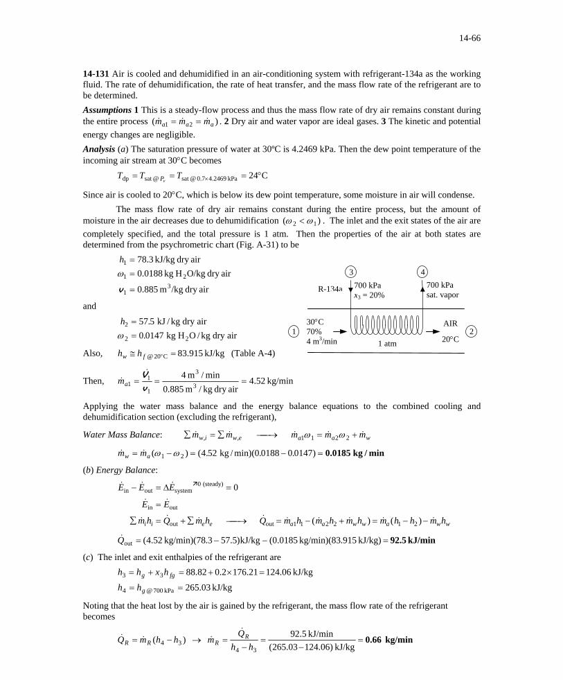
14-131 Air is cooled and dehumidified in an air-conditioning system with refrigerant-134a as the working fluid. The rate of dehumidification, the rate of heat transfer, and the mass flow rate of the refrigerant are to be determined. Assumptions 1 This is a steady-flow process and thus the mass flow rate of dry air remains constant during the entire process ( . 2 Dry air and water vapor are ideal gases. 3 The kinetic and potential energy changes are negligible.
& & & )m m ma a a1 2= =
Analysis (a) The saturation pressure of water at 30ºC is 4.2469 kPa. Then the dew point temperature of the incoming air stream at 30°C becomes C24kPa 2469.47.0@sat @sat dp °=== ×TTT
vP
Since air is cooled to 20°C, which is below its dew point temperature, some moisture in air will condense. The mass flow rate of dry air remains constant during the entire process, but the amount of moisture in the air decreases due to dehumidification ( )ω ω2 1< . The inlet and the exit states of the air are completely specified, and the total pressure is 1 atm. Then the properties of the air at both states are determined from the psychrometric chart (Fig. A-31) to be
airdry /kgm 885.0
airdry O/kgH kg 0188.0airdry kJ/kg 3.78
31
21
1
=
==
v
ωh
4 3
30°C 70% 4 m3/min 1 atm
700 kPa x3 = 20%
AIR
20°C
700 kPa sat. vapor
21
R-134a
and
h2 57 5
0 0147==
..
kJ / kg dry air kg H O / kg dry air2 2ω
Also, (Table A-4) kJ/kg 915.83C20@ =≅ °fw hh
Then, kg/min 52.4airdry kg/m 885.0
min/m 43
3
1
11 ===
vV&
& am
Applying the water mass balance and the energy balance equations to the combined cooling and dehumidification section (excluding the refrigerant),
Water Mass Balance: ∑ = ∑ ⎯ →⎯ =& & & &, ,m m m mw i w e a a w1 1 2 2ω ω + &m
& & ( ) ( . . . )m mw a= − = − =ω ω1 kg / min)(2 4 52 0 0188 0 0147 0.0185 kg / min
(b) Energy Balance:
& & &
& &
& & & & & ( & & ) & ( ) &
E E E
E E
m h Q m h Q m h m h m h m h h m hi i e e a a w w a w w
14-132 Air is cooled and dehumidified in an air-conditioning system with refrigerant-134a as the working fluid. The rate of dehumidification, the rate of heat transfer, and the mass flow rate of the refrigerant are to be determined. Assumptions 1 This is a steady-flow process and thus the mass flow rate of dry air remains constant during the entire process. 2 Dry air and water vapor are ideal gases. 3 The kinetic and potential energy changes are negligible. Analysis (a) The dew point temperature of the incoming air stream at 30°C is
C24
kPa 973.2kPa) 247.4)(7.0(
kPa 973.2@sat @sat dp
C30@sat 1111
°===
==== °
TTT
PPP
vP
gv φφ
Since air is cooled to 20°C, which is below its dew point temperature, some of the moisture in the air will condense.
30°C 70% 4 m3/min 95 kPa
700 kPa x3 = 20%
AIR
20°C
3 4700 kPa sat. vapor
21
R-134a
The amount of moisture in the air decreases due to dehumidification ( )ω ω2 1< . The inlet and the exit states of the air are completely specified, and the total pressure is 95 kPa. The properties of the air at both states are determined to be
airdry kJ/kg 50.81
kJ/kg) 555.6(0.0201)(2+C)C)(30kJ/kg 005.1(
airdry O/kgH kg 0.0201kPa )97.2(95kPa) 97.2(622.0 622.0
airdry kg/m 945.0kPa 03.92
K) K)(303kg/mkPa 287.0(
kPa 03.9297.295
1111
211
11
33
1
11
111
=
°°⋅=+=
=−
=−
=
=⋅⋅
==
=−=−=
gp
v
v
a
a
va
hTch
PPP
PTR
PPP
ω
ω
v
and
airdry kJ/kg 94.59
kJ/kg) 537.4(0.0157)(2+C)C)(20kJ/kg 005.1(
airdry O/kgH kg 0.0157kPa )3392.2(95kPa) 3392.2(622.0 622.0
kPa 3392.2)00.1(
2222
222
22
C20@sat 222
=
°°⋅=+=
=−
=−
=
=== °
gp
v
v
gv
hTch
PPP
PPP
ω
ω
φ
Also, kJ/kg 915.83C20@ =≅ °fw hh (Table A-4)
Then,
kg/min 23.4airdry kg/m 945.0
min/m 43
3
1
11 ===
vV&
& am
Applying the water mass balance and the energy balance equations to the combined cooling and dehumidification section (excluding the refrigerant),
Water Mass Balance: ∑ = ∑ ⎯ →⎯ =& & & &, ,m m m mw i w e a a w1 1 2 2ω ω + &m
& & ( ) ( . . . )m mw a= − = − =ω ω1 kg / min)(2 4 23 0 0201 0 0157 0.0186 kg / min
(c) The inlet and exit enthalpies of the refrigerant are
kJ/kg 03.265
kJ/kg 06.12421.1762.082.88
kPa 700@4
33
==
=×+=+=
g
fgg
hh
hxhh
Noting that the heat lost by the air is gained by the refrigerant, the mass flow rate of the refrigerant is determined from
kg/min 0.636=
−=
−=
−=
kJ/kg )06.12403.265(kJ/min 7.89
)(
34
34
hhQ
m
hhmQ
RR
RR&
&
&&
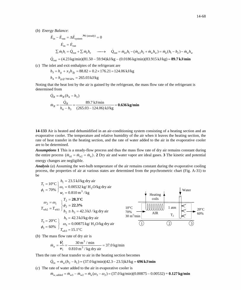
14-133 Air is heated and dehumidified in an air-conditioning system consisting of a heating section and an evaporative cooler. The temperature and relative humidity of the air when it leaves the heating section, the rate of heat transfer in the heating section, and the rate of water added to the air in the evaporative cooler are to be determined. Assumptions 1 This is a steady-flow process and thus the mass flow rate of dry air remains constant during the entire process ( . 2 Dry air and water vapor are ideal gases. 3 The kinetic and potential energy changes are negligible.
& & & )m m ma a a1 2= =
Analysis (a) Assuming the wet-bulb temperature of the air remains constant during the evaporative cooling process, the properties of air at various states are determined from the psychrometric chart (Fig. A-31) to be
kg/m 810.0
airdry O/kgHkg/ 00532.0airdry kJ/kg 5.23
%70C10
31
21
1
1
1
===
⎭⎬⎫
=°=
v
ωφ
hT
10°C 70% 30 m3/min
1 atm
T2
Heating coils
3
AIR
2 1
Water
airdry kg/kJ 3.42
32
2
2
wb3wb2
12
=≅=
°=
⎭⎬⎫
==
hh
T
TT22.3%
C28.3φ
ωω
20°C60%
C1.15
airdry O/kgHkg/ 00875.0airdry kJ/kg 3.42
%60C20
3
23
3
3
3
°===
⎭⎬⎫
=°=
wbT
hT
ωφ
(b) The mass flow rate of dry air is
kg/min 0.37airdry kg/m 810.0
min/m 303
3
1
1 ===v
V&& am
Then the rate of heat transfer to air in the heating section becomes kJ/min 696=−=−= kJ/kg)5.23.3kg/min)(42 0.37()( 12in hhmQ a&
&
(c) The rate of water added to the air in evaporative cooler is kg/min 0.127=0.00532)00875kg/min)(0. 0.37()( 2323added , −=−=−= ωωawww mmmm &&&&
14-134 EES Problem 14-133 is reconsidered. The effect of total pressure in the range 94 to 104 kPa on the results required in the problem is to be studied. Analysis The problem is solved using EES, and the solution is given below. P=101.325 [kPa] Tdb[1] =10 [C] Rh[1] = 0.70 Vol_dot[1]= 50 [m^3/min] Tdb[3] = 20 [C] Rh[3] = 0.60 P[1]=P P[2]=P[1] P[3]=P[1] "Energy balance for the steady-flow heating process 1 to 2:" "We neglect the PE of the flow. Since we don't know the cross sectional area of the flow streams, we also neglect theKE of the flow." E_dot_in - E_dot_out = DELTAE_dot_sys DELTAE_dot_sys = 0 [kJ/min] E_dot_in = m_dot_a*h[1]+Q_dot_in E_dot_out = m_dot_a*h[2] "Conservation of mass of dry air during mixing: m_dot_a = constant" m_dot_a = Vol_dot[1]/v[1] "Conservation of mass of water vapor during the heating process:" m_dot_a*w[1] = m_dot_a*w[2] "Conservation of mass of water vapor during the evaporative cooler process:" m_dot_a*w[2]+m_dot_w = m_dot_a*w[3] "During the evaporative cooler process:" Twb[2] = Twb[3] Twb[3] =WETBULB(AirH2O,T=Tdb[3],P=P[3],R=Rh[3]) h[1]=ENTHALPY(AirH2O,T=Tdb[1],P=P[1],R=Rh[1]) v[1]=VOLUME(AirH2O,T=Tdb[1],P=P[1],R=Rh[1]) w[1]=HUMRAT(AirH2O,T=Tdb[1],P=P[1],R=Rh[1]) {h[2]=ENTHALPY(AirH2O,T=Tdb[2],P=P[2],B=Twb[2])} h[2]=h[3] Tdb[2]=TEMPERATURE(AirH2O,h=h[2],P=P[2],w=w[2]) w[2]=HUMRAT(AirH2O,T=Tdb[2],P=P[2],R=Rh[2]) h[3]=ENTHALPY(AirH2O,T=Tdb[3],P=P[3],R=Rh[3]) w[3]=HUMRAT(AirH2O,T=Tdb[3],P=P[3],R=Rh[3])
14-135 Air is heated and dehumidified in an air-conditioning system consisting of a heating section and an evaporative cooler. The temperature and relative humidity of the air when it leaves the heating section, the rate of heat transfer in the heating section, and the rate at which water is added to the air in the evaporative cooler are to be determined. Assumptions 1 This is a steady-flow process and thus the mass flow rate of dry air remains constant during the entire process ( . 2 Dry air and water vapor are ideal gases. 3 The kinetic and potential energy changes are negligible.
& & & )m m ma a a1 2= =
Analysis (a) Assuming the wet-bulb temperature of the air remains constant during the evaporative cooling process, the properties of air at various states are determined to be
14-136 Conditioned air is to be mixed with outside air. The ratio of the dry air mass flow rates of the conditioned- to-outside air, and the temperature of the mixture are to be determined. Assumptions 1 Steady operating conditions exist. 2 Dry air and water vapor are ideal gases. 3 The kinetic and potential energy changes are negligible. 4 The mixing chamber is adiabatic. Properties The properties of each inlet stream are determined from the psychrometric chart (Fig. A-31) to be
h1 34 3
0 0084==
..
kJ / kg dry air kg H O / kg dry air1 2ω
and
h2 68 5
0 0134==
..
kJ / kg dry air kg H O / kg dry air2 2ω
Analysis The ratio of the dry air mass flow rates of the Conditioned air to the outside air can be determined from
P = 1 atm T3
13°C 90%
34°C 40%
3
2
1
13
32
13
32
2
1
hhhh
mm
a
a
−−
=−−
=ωωωω
&
&
But state 3 is not completely specified. However, we know that state 3 is on the straight line connecting states 1 and 2 on the psychrometric chart. At the intersection point of this line and φ = 60% line we read (b) T3 = °23.5 C
ω 3 2 kg H O / kg dry air
kJ / kg dry air==
0 01095133
..h
Therefore, the mixture will leave at 23.5°C. The ratio is determined by substituting the specific humidity (or enthalpy) values into the above relation,
& / &m ma a1 2
(a) &
&
. .
. .mm
a
a
1
2
0 0134 0 01090 0109 0 0084
=−−
= 1.00
Therefore, the mass flow rate of each stream must be the same.
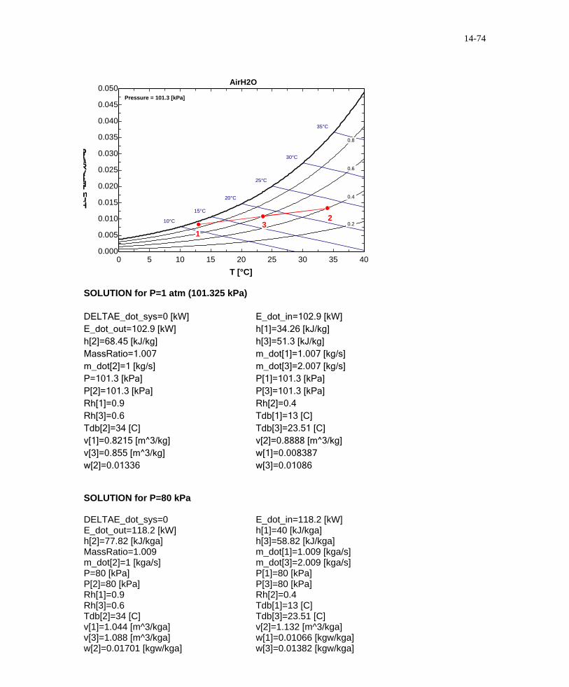
14-137 EES Problem 14-136 is reconsidered. The desired quantities are to be determined using EES at 1 atm and 80 kPa pressures. Analysis The problem is solved using EES, and the solution is given below. "Without loss of generality assume the mass flow rate of the outside air is m_dot[2] = 1 kg/s." P=101.325 [kPa] Tdb[1] =13 [C] "State 1 is the conditioned air" Rh[1] = 0.90 Tdb[2] =34 [C] "State 2 is the outside air" Rh[2] = 0.40 Rh[3] = 0.60 P[1]=P P[2]=P[1] P[3]=P[1] m_dot[2] = 1 [kg/s] MassRatio = m_dot[1]/m_dot[2] "Energy balance for the steady-flow mixing process:" "We neglect the PE of the flow. Since we don't know the cross sectional area of the flow streams, we also neglect theKE of the flow." E_dot_in - E_dot_out = DELTAE_dot_sys DELTAE_dot_sys = 0 [kW] E_dot_in = m_dot[1]*h[1]+m_dot[2]*h[2] E_dot_out = m_dot[3]*h[3] "Conservation of mass of dry air during mixing:" m_dot[1]+m_dot[2] = m_dot[3] "Conservation of mass of water vapor during mixing:" m_dot[1]*w[1]+m_dot[2]*w[2] = m_dot[3]*w[3] h[1]=ENTHALPY(AirH2O,T=Tdb[1],P=P[1],R=Rh[1]) v[1]=VOLUME(AirH2O,T=Tdb[1],P=P[1],R=Rh[1]) w[1]=HUMRAT(AirH2O,T=Tdb[1],P=P[1],R=Rh[1]) h[2]=ENTHALPY(AirH2O,T=Tdb[2],P=P[2],R=Rh[2]) v[2]=VOLUME(AirH2O,T=Tdb[2],P=P[2],R=Rh[2]) w[2]=HUMRAT(AirH2O,T=Tdb[2],P=P[2],R=Rh[2]) Tdb[3]=TEMPERATURE(AirH2O,h=h[3],P=P[3],R=Rh[3]) w[3]=HUMRAT(AirH2O,T=Tdb[3],P=P[3],R=Rh[3]) v[3]=VOLUME(AirH2O,T=Tdb[3],P=P[3],w=w[3])
14-138 [Also solved by EES on enclosed CD] Waste heat from the cooling water is rejected to air in a natural-draft cooling tower. The mass flow rate of the cooling water, the volume flow rate of air, and the mass flow rate of the required makeup water are to be determined. Assumptions 1 Steady operating conditions exist. 2 Dry air and water vapor are ideal gases. 3 The kinetic and potential energy changes are negligible. 4 The cooling tower is adiabatic. Analysis (a) The mass flow rate of dry air through the tower remains constant ( , but the mass flow rate of liquid water decreases by an amount equal to the amount of water that vaporizes in the tower during the cooling process. The water lost through evaporation is made up later in the cycle using water at 27°C. Applying the mass balance and the energy balance equations yields
& & & )m m ma a a1 2= =
Dry Air Mass Balance: AIR EXIT
37°C saturated
2 ∑ = ∑ ⎯ →⎯ = =& & & & &m ma a1 2 , ,m m ma i a e a
The mass flow rate of the cooling water is determined by applying the steady flow energy balance equation on the cooling water,
& & ( & & ) & [ & & ( )]
& & [ . ( . . )] & ( .
Q m h m m h m h m m h
m h m h m h hawaste makeup= − − = − − −
= − − − = −3 3 3 4 3 3 3 2 1 4
3 3 3 4 3 3 41 0 706 0 0412 0 0109 0 9786
ω ω
)
kg/s 768.1=⎯→⎯×− 33 kJ/kg .19)1139786.090.175(=kJ/s 000,50 mm &&
and & . & ( . )( .m ma = =0 706 0 706 76813 kg / s) = 542.3 kg / s(b) Then the volume flow rate of air into the cooling tower becomes /sm 463.1 3=== )kg/m 4kg/s)(0.85 3.542( 3
11 vV am&&
(c) The mass flow rate of the required makeup water is determined from & & ( ) ( .m mamakeup kg / s)(0.0412 .0109)= − = − =ω ω2 1 542 3 0 16.4 kg / s
14-139 EES Problem 14-138 is reconsidered. The effect of air inlet wet-bulb temperature on the required air volume flow rate and the makeup water flow rate is to be investigated. Analysis The problem is solved using EES, and the solution is given below. "Input Data" P_atm =101.325 [kPa] T_db_1 = 23 [C] T_wb_1 = 18 [C] T_db_2 = 37 [C] RH_2 = 100/100 "%. relative humidity at state 2, saturated condition" Q_dot_waste = 50 [MW]*Convert(MW, kW) T_cw_3 = 42 [C] "Cooling water temperature at state 3" T_cw_4 = 27 [C] "Cooling water temperature at state 4" "Dry air mass flow rates:" "RH_1 is the relative humidity at state 1 on a decimal basis" v_1=VOLUME(AirH2O,T=T_db_1,P=P_atm,R=RH_1) T_wb_1 = WETBULB(AirH2O,T=T_db_1,P=P_atm,R=RH_1) m_dot_a_1 = Vol_dot_1/v_1 "Conservaton of mass for the dry air (ma) in the SSSF mixing device:" m_dot_a_in - m_dot_a_out = DELTAm_dot_a_cv m_dot_a_in = m_dot_a_1 m_dot_a_out = m_dot_a_2 DELTAm_dot_a_cv = 0 "Steady flow requirement" "Conservation of mass for the water vapor (mv) and cooling water for the SSSF process:" m_dot_w_in - m_dot_w_out = DELTAm_dot_w_cv m_dot_w_in = m_dot_v_1 + m_dot_cw_3 m_dot_w_out = m_dot_v_2+m_dot_cw_4 DELTAm_dot_w_cv = 0 "Steady flow requirement" w_1=HUMRAT(AirH2O,T=T_db_1,P=P_atm,R=RH_1) m_dot_v_1 = m_dot_a_1*w_1 w_2=HUMRAT(AirH2O,T=T_db_2,P=P_atm,R=RH_2) m_dot_v_2 = m_dot_a_2*w_2 "Conservation of energy for the SSSF cooling tower process:" "The process is adiabatic and has no work done, ngelect ke and pe" E_dot_in_tower - E_dot_out_tower = DELTAE_dot_tower_cv E_dot_in_tower= m_dot_a_1 *h[1] + m_dot_cw_3*h_w[3] E_dot_out_tower = m_dot_a_2*h[2] + m_dot_cw_4*h_w[4] DELTAE_dot_tower_cv = 0 "Steady flow requirement" h[1]=ENTHALPY(AirH2O,T=T_db_1,P=P_atm,w=w_1) h[2]=ENTHALPY(AirH2O,T=T_db_2,P=P_atm,w=w_2) h_w[3]=ENTHALPY(steam,T=T_cw_3,x=0) h_w[4]=ENTHALPY(steam,T=T_cw_4,x=0) "Energy balance on the external heater determines the cooling water flow rate:" E_dot_in_heater - E_dot_out_heater = DELTAE_dot_heater_cv E_dot_in_heater = Q_dot_waste + m_dot_cw_4*h_w[4] E_dot_out_heater = m_dot_cw_3 * h_w[3] DELTAE_dot_heater_cv = 0 "Steady flow requirement"
"Conservation of mass on the external heater gives the makeup water flow rate." "Note: The makeup water flow rate equals the amount of water vaporized in the cooling tower." m_dot_cw_in - m_dot_cw_out = DELTAm_dot_cw_cv m_dot_cw_in = m_dot_cw_4 + m_dot_makeup m_dot_cw_out = m_dot_cw_3 DELTAm_dot_cw_cv = 0 "Steady flow requirement"
14-140 Atmospheric air enters an air-conditioning system at a specified pressure, temperature, and relative humidity. The heat transfer, the rate of condensation of water, and the mass flow rate of the refrigerant are to be determined. Assumptions 1 This is a steady-flow process and thus the mass flow rate of dry air remains constant during the entire process ( . 2 Dry air and water vapor are ideal gases. 3 The kinetic and potential energy changes are negligible.
& & & )m m ma a a1 2= =
Analysis The inlet and exit states of the air are completely specified, and the total pressure is 1 atm. The properties of the air at the inlet and exit states may be determined from the psychrometric chart (Figure A-31) or using EES psychrometric functions to be (we used EES)
airdry O/kgH kg 002885.0airdry kJ/kg 45.27
airdry kg/m 8847.0
airdry O/kgH kg 01880.0airdry kJ/kg 24.78
22
2
31
21
1
===
==
ω
ω
h
h
v
The mass flow rate of dry air is
kg/min 521.4m 0.8847
/minm 43
3
1
1 ===vV&
& am
The mass flow rates of vapor at the inlet and exit are kg/min 0.0850kg/min) 521.4)(01880.0(11 === av mm && ω
1 atm
Cooling coils
12Condensate
R-134a 350 kPa x = 0.20
Condensate removal
350 kPa x = 1.0
T1 =30°C φ 1 = 70% 4 m3/min
T2 =20°C φ 2 = 20%
20°C
kg/min 0.01304kg/min) 521.4)(002885.0(22 === av mm && ω An energy balance on the control volume gives 22out1 wwaa hmhmQhm &&&& ++=where the the enthalpy of condensate water is
4)-A (Table kJ/kg 91.83C20 @2 == °fw hh
and the rate of condensation of water vapor is kg/min 0.07196=−=−= 01304.00850.021 vvw mmm &&& Substituting,
14-141 An uninsulated tank contains moist air at a specified state. Water is sprayed into the tank until the relative humidity in the tank reaches a certain value. The amount of water supplied to the tank, the final pressure in the tank, and the heat transfer during the process are to be determined. Assumptions 1 Dry air and water vapor are ideal gases. 2 The kinetic and potential energy changes are negligible. Analysis The initial state of the moist air is completely specified. The properties of the air at the inlet state may be determined from the psychrometric chart (Figure A-31) or using EES psychrometric functions to be (we used EES)
airdry kg/m 6863.0
airdry O/kgH kg 005433.0airdry kJ/kg 16.49
31
21
1
=
==
v
ωh
The initial mass in the tank is
kg 7285.0m 0.6863
m 5.03
3
1
1 ===vV
am
The partial pressure of dry air in the tank is
kPa 8.128)m (0.5
K) 2735kJ/kg.K)(3 kg)(0.287 (0.7285 32
2 =+
==V
TRmP aa
a
Then, the pressure of moist air in the tank is determined from
⎟⎟⎠
⎞⎜⎜⎝
⎛+=⎟⎟
⎠
⎞⎜⎜⎝
⎛+=
622.01kPa) 8.128(
622.01 22
22ωω
aPP
We cannot fix the final state explicitly by a hand-solution. However, using EES which has built-in functions for moist air properties, the final state properties are determined to be
airdry kJ/kg 97.972
2
==
hP kPa 133.87
airdry kg/m 6867.0
airdry O/kgH kg 02446.03
2
22
=
=
v
ω
The partial pressures at the initial and final states are
kPa 07.581.12887.133
kPa 87.128126.1130
kPa 126.1kPa) 6291.5(20.0
222
111
Csat@3511
=−=−==−=−=
=== °
av
va
v
PPPPPP
PP φ
The specific volume of water at 35ºC is /kgm 205.25 3
C@35 g21 === °vvv ww
The internal energies per unit mass of dry air in the tank are kJ/kg 44.39205.25126.1005433.06863.087.12816.491111111 −=××−×−=−−= wva PwPhu vv kJ/kg 396.6205.2507.502446.06867.081.12897.972222222 =××−×−=−−= wva PwPhu vv The enthalpy of water entering the tank from the supply line is kJ/kg 34.209C@50 f1 == °hhw
The internal energy of water vapor at the final state is kJ/kg 7.2422C@35 g2 == °uuw
The amount of water supplied to the tank is kg 0.01386==−= 0.005433)-6kg)(0.0244 7285.0()( 12 ωωaw mm An energy balance on the system gives
14-142 Air flows steadily through an isentropic nozzle. The pressure, temperature, and velocity of the air at the nozzle exit are to be determined. Assumptions 1 This is a steady-flow process and thus the mass flow rate of dry air remains constant during the entire process ( . 2 Dry air and water vapor are ideal gases. 3 The kinetic and potential energy changes are negligible.
& & & )m m ma a a1 2= =
Analysis The inlet state of the air is completely specified, and the total pressure is 200 kPa. The properties of the air at the inlet state may be determined from the psychrometric chart (Figure A-31) or using EES psychrometric functions to be (we used EES)
Air 35ºC 200 kPa50% RH
T2P2V2
process) c(isentropiair dry kJ/kg.K 613.5
on)condensati (noair dry O/kgH kg 008803.0airdry kJ/kg 65.57
21
221
1
====
=
ss
hωω
We assume that the relative humidity at the nozzle exit is 100 percent since there is no condensation in the nozzle. Other exit state properties can be determined using EES built-in functions for moist air. The results are
C20
kPa 168.2°=
==
2
2
2 airdry kJ/kg 53.42
TPh
An energy balance on the control volume gives the velocity at the exit
Fundamentals of Engineering (FE) Exam Problems 14-143 A room is filled with saturated moist air at 25°C and a total pressure of 100 kPa. If the mass of dry air in the room is 100 kg, the mass of water vapor is (a) 0.52 kg (b) 1.97 kg (c) 2.96 kg (d) 2.04 kg (e) 3.17 kg Answer (d) 2.04 kg Solution Solved by EES Software. Solutions can be verified by copying-and-pasting the following lines on a blank EES screen. (Similar problems and their solutions can be obtained easily by modifying numerical values). T1=25 "C" P=100 "kPa" m_air=100 "kg" RH=1 P_g=PRESSURE(Steam_IAPWS,T=T1,x=0) RH=P_v/P_g P_air=P-P_v w=0.622*P_v/(P-P_v) w=m_v/m_air "Some Wrong Solutions with Common Mistakes:" W1_vmass=m_air*w1; w1=0.622*P_v/P "Using P instead of P-Pv in w relation" W2_vmass=m_air "Taking m_vapor = m_air" W3_vmass=P_v/P*m_air "Using wrong relation" 14-144 A room contains 50 kg of dry air and 0.6 kg of water vapor at 25°C and 95 kPa total pressure. The relative humidity of air in the room is (a) 1.2% (b) 18.4% (c) 56.7% (d) 65.2% (e) 78.0% Answer (c) 56.7% Solution Solved by EES Software. Solutions can be verified by copying-and-pasting the following lines on a blank EES screen. (Similar problems and their solutions can be obtained easily by modifying numerical values). T1=25 "C" P=95 "kPa" m_air=50 "kg" m_v=0.6 "kg" w=0.622*P_v/(P-P_v) w=m_v/m_air P_g=PRESSURE(Steam_IAPWS,T=T1,x=0) RH=P_v/P_g "Some Wrong Solutions with Common Mistakes:" W1_RH=m_v/(m_air+m_v) "Using wrong relation" W2_RH=P_g/P "Using wrong relation"
14-145 A 40-m3 room contains air at 30°C and a total pressure of 90 kPa with a relative humidity of 75 percent. The mass of dry air in the room is (a) 24.7 kg (b) 29.9 kg (c) 39.9 kg (d) 41.4 kg (e) 52.3 kg Answer (c) 39.9 kg Solution Solved by EES Software. Solutions can be verified by copying-and-pasting the following lines on a blank EES screen. (Similar problems and their solutions can be obtained easily by modifying numerical values). V=40 "m^3" T1=30 "C" P=90 "kPa" RH=0.75 P_g=PRESSURE(Steam_IAPWS,T=T1,x=0) RH=P_v/P_g P_air=P-P_v R_air=0.287 "kJ/kg.K" m_air=P_air*V/(R_air*(T1+273)) "Some Wrong Solutions with Common Mistakes:" W1_mass=P_air*V/(R_air*T1) "Using C instead of K" W2_mass=P*V/(R_air*(T1+273)) "Using P instead of P_air" W3_mass=m_air*RH "Using wrong relation" 14-146 A room contains air at 30°C and a total pressure of 96.0 kPa with a relative humidity of 75 percent. The partial pressure of dry air is (a) 82.0 kPa (b) 85.8 kPa (c) 92.8 kPa (d) 90.6 kPa (e) 72.0 kPa Answer (c) 92.8 kPa Solution Solved by EES Software. Solutions can be verified by copying-and-pasting the following lines on a blank EES screen. (Similar problems and their solutions can be obtained easily by modifying numerical values). T1=30 "C" P=96 "kPa" RH=0.75 P_g=PRESSURE(Steam_IAPWS,T=T1,x=0) RH=P_v/P_g P_air=P-P_v "Some Wrong Solutions with Common Mistakes:" W1_Pair=P_v "Using Pv as P_air" W2_Pair=P-P_g "Using wrong relation" W3_Pair=RH*P "Using wrong relation" 14-147 The air in a house is at 20°C and 50 percent relative humidity. Now the air is cooled at constant pressure. The temperature at which the moisture in the air will start condensing is (a) 8.7°C (b) 11.3°C (c) 13.8°C (d) 9.3°C (e) 10.0°C Answer (d) 9.3°C
Solution Solved by EES Software. Solutions can be verified by copying-and-pasting the following lines on a blank EES screen. (Similar problems and their solutions can be obtained easily by modifying numerical values). T1=25 "C" RH1=0.50 P_g=PRESSURE(Steam_IAPWS,T=T1,x=0) RH1=P_v/P_g T_dp=TEMPERATURE(Steam_IAPWS,x=0,P=P_v) "Some Wrong Solutions with Common Mistakes:" W1_Tdp=T1*RH1 "Using wrong relation" W2_Tdp=(T1+273)*RH1-273 "Using wrong relation" W3_Tdp=WETBULB(AirH2O,T=T1,P=P1,R=RH1); P1=100 "Using wet-bulb temperature" 14-148 On the psychrometric chart, a cooling and dehumidification process appears as a line that is (a) horizontal to the left, (b) vertical downward, (c) diagonal upwards to the right (NE direction) (d) diagonal upwards to the left (NW direction) (e) diagonal downwards to the left (SW direction) Answer (e) diagonal downwards to the left (SW direction) 14-149 On the psychrometric chart, a heating and humidification process appears as a line that is (a) horizontal to the right, (b) vertical upward, (c) diagonal upwards to the right (NE direction) (d) diagonal upwards to the left (NW direction) (e) diagonal downwards to the right (SE direction) Answer (c) diagonal upwards to the right (NE direction) 14-150 An air stream at a specified temperature and relative humidity undergoes evaporative cooling by spraying water into it at about the same temperature. The lowest temperature the air stream can be cooled to is (a) the dry bulb temperature at the given state (b) the wet bulb temperature at the given state (c) the dew point temperature at the given state (d) the saturation temperature corresponding to the humidity ratio at the given state (e) the triple point temperature of water Answer (a) the dry bulb temperature at the given state 14-151 Air is cooled and dehumidified as it flows over the coils of a refrigeration system at 85 kPa from 30°C and a humidity ratio of 0.023 kg/kg dry air to 15°C and a humidity ratio of 0.015 kg/kg dry air. If the mass flow rate of dry air is 0.7 kg/s, the rate of heat removal from the air is (a) 5 kJ/s (b) 10 kJ/s (c) 15 kJ/s (d) 20 kJ/s (e) 25 kJ/s Answer (e) 25 kJ/s
Solution Solved by EES Software. Solutions can be verified by copying-and-pasting the following lines on a blank EES screen. (Similar problems and their solutions can be obtained easily by modifying numerical values). P=85 "kPa" T1=30 "C" w1=0.023 T2=15 "C" w2=0.015 m_air=0.7 "kg/s" m_water=m_air*(w1-w2) h1=ENTHALPY(AirH2O,T=T1,P=P,w=w1) h2=ENTHALPY(AirH2O,T=T2,P=P,w=w2) h_w=ENTHALPY(Steam_IAPWS,T=T2,x=0) Q=m_air*(h1-h2)-m_water*h_w "Some Wrong Solutions with Common Mistakes:" W1_Q=m_air*(h1-h2) "Ignoring condensed water" W2_Q=m_air*Cp_air*(T1-T2)-m_water*h_w; Cp_air = 1.005 "Using dry air enthalpies" W3_Q=m_air*(h1-h2)+m_water*h_w "Using wrong sign" 14-152 Air at a total pressure of 90 kPa, 15°C, and 75 percent relative humidity is heated and humidified to 25°C and 75 percent relative humidity by introducing water vapor. If the mass flow rate of dry air is 4 kg/s, the rate at which steam is added to the air is (a) 0.032 kg/s (b) 0.013 kg/s (c) 0.019 kg/s (d) 0.0079 kg/s (e) 0 kg/s Answer (a) 0.032 kg/s Solution Solved by EES Software. Solutions can be verified by copying-and-pasting the following lines on a blank EES screen. (Similar problems and their solutions can be obtained easily by modifying numerical values). P=90 "kPa" T1=15 "C" RH1=0.75 T2=25 "C" RH2=0.75 m_air=4 "kg/s" w1=HUMRAT(AirH2O,T=T1,P=P,R=RH1) w2=HUMRAT(AirH2O,T=T2,P=P,R=RH2) m_water=m_air*(w2-w1) "Some Wrong Solutions with Common Mistakes:" W1_mv=0 "sine RH = constant" W2_mv=w2-w1 "Ignoring mass flow rate of air" W3_mv=RH1*m_air "Using wrong relation" 14-153 ··· 14-157 Design and Essay Problems