68
OPERATING INSTRUCTIONS V200 Work Station Extended, V300 Work Station Extended Safety camera system GB

O P E R A T I N G I N S T R U C T I O N S
V200 Work Station Extended,
V300 Work Station Extended
Safety camera system
GB

Operating Instructions
V200/V300
2 © SICK AG • Industrial Safety Systems • Germany • All rights reserved 8012227/TA69/2009-11-27
This document is protected by the law of copyright, whereby all rights established therein remain with the
company SICK AG. Reproduction of this document or parts of this document is only permissible within the limits
of the legal determination of Copyright Law. Alteration or abridgement of the document is not permitted without
the explicit written approval of the company SICK AG.

Operating Instructions
V200/V300
8012227/TA69/2009-11-27 © SICK AG • Industrial Safety Systems • Germany • All rights reserved 3
Contents
Contents
1 About this document.........................................................................................................6
1.1 Function of this document....................................................................................6
1.2 Target group ..........................................................................................................6
1.3 Information depth .................................................................................................6
1.4 Scope .....................................................................................................................7
1.5 Abbreviations used ...............................................................................................7
1.6 Symbols used ........................................................................................................7
2 On safety.............................................................................................................................9
2.1 Qualified safety personnel....................................................................................9
2.2 Applications of the device...................................................................................10
2.3 Correct use ..........................................................................................................10
2.4 General safety notes and protective measures ................................................11
2.5 Environmental protection ...................................................................................12
2.5.1 Disposal .............................................................................................12
2.5.2 Separation of materials ....................................................................12
3 Product description.........................................................................................................13
3.1 Special features ..................................................................................................13
3.2 Operating principle of the device .......................................................................13
3.3 Application examples..........................................................................................14
3.4 Configurable functions........................................................................................15
3.4.1 Restart interlock................................................................................15
3.4.2 External device monitoring (EDM)....................................................16
3.5 Status indicators .................................................................................................17
3.5.1 Status LEDs of the V200/V300 .......................................................17
3.5.2 Diagnostics LEDs of the V200/V300...............................................18
4 Mounting ..........................................................................................................................19
4.1 Checking the dimensions of the protective field...............................................19
4.1.1 Protective field dimensions allowed at a resolution of
20 mm ...............................................................................................19
4.1.2 Protective field dimensions allowed at a resolution of
24 mm ...............................................................................................20
4.1.3 Protective field dimensions allowed at a resolution of
30 mm ...............................................................................................20
4.2 Determining the safety distance ........................................................................21
4.2.1 Safety distance according to prEN ISO 13�855 and
EN ISO 13�857...................................................................................22
4.2.2 Safety distance if OSHA and ANSI are applicable ...........................24
4.3 Avoiding unmonitored areas ..............................................................................25
4.4 Steps for mounting the safety camera system..................................................27
4.4.1 Mounting on a frame ........................................................................28
4.4.2 Mounting in a frame..........................................................................29
4.4.3 Mounting the reflective tape ............................................................30

Operating Instructions
V200/V300
4 © SICK AG • Industrial Safety Systems • Germany • All rights reserved 8012227/TA69/2009-11-27
Contents
5 Electrical installation .....................................................................................................33
5.1 System connection M12�×8...............................................................................34
5.2 Connecting the V200/V300 without external device monitoring (EDM),
without internal restart interlock and without external key-operated
pushbutton for teach-in......................................................................................35
5.3 Connecting the V200/V300 with external device monitoring (EDM),
with internal restart interlock and with external key-operated
pushbutton for teach-in......................................................................................35
5.4 Two V200/V300 with synchronisation ..............................................................37
5.5 Connection diagrams .........................................................................................38
5.5.1 V200/V300 on UE410 Flexi with external device monitoring
(EDM) and with restart interlock both for V200/V300 as well
as for emergency switching off ........................................................38
5.5.2 V200/V300 on UE103OS with external device monitoring
(EDM) and internal restart interlock ................................................39
6 Application examples .....................................................................................................40
6.1 Application with one V200/V300 ......................................................................40
6.2 Application with two V200/V300 ......................................................................41
6.3 Application with safe access on three sides (ergonomic workplace
design).................................................................................................................42
6.4 Application with automatic material transport to the workstation ..................43
7 Commissioning................................................................................................................44
7.1 Test notes............................................................................................................44
7.2 Pre-commissioning tests ....................................................................................44
7.3 Regular inspection of the protective device by qualified safety
personnel ............................................................................................................44
7.4 Tests of the protective device by a specialist or authorised personnel ..........45
8 Configuration...................................................................................................................46
8.1 Teach-in...............................................................................................................46
8.2 Internal restart interlock.....................................................................................48
8.3 External device monitoring.................................................................................49
8.4 Locking the internal teach-in key.......................................................................50
9 Care and maintenance ...................................................................................................51
10 Fault diagnosis................................................................................................................52
10.1 In the event of faults or errors ...........................................................................52
10.2 SICK support .......................................................................................................52
10.3 Warnings and error messages of the LEDs.......................................................53
11 Technical specifications ................................................................................................54
11.1 Data sheet...........................................................................................................54
11.2 Dimensional drawings ........................................................................................58
11.2.1 Dimensional drawing V200/V300...................................................58
11.2.2 Dimensional drawing, mounting kit .................................................59
12 Ordering information ......................................................................................................60
12.1 Safety camera systems ......................................................................................60
12.2 Accessories .........................................................................................................61

Operating Instructions
V200/V300
8012227/TA69/2009-11-27 © SICK AG • Industrial Safety Systems • Germany • All rights reserved 5
Contents
13 Annex ................................................................................................................................62
13.1 EC declaration of conformity ..............................................................................62
13.2 Checklist for the manufacturer ..........................................................................64
13.3 List of tables........................................................................................................65
13.4 List of illustrations...............................................................................................65
Chapter 1 Operating Instructions
V200/V300
6 © SICK AG • Industrial Safety Systems • Germany • All rights reserved 8012227/TA69/2009-11-27
About this document
1 About this document
Please read this chapter carefully before working with the documentation and the V200
Work Station Extended or V300 Work Station Extended safety camera system, referred to
in the following as V200/V300 for short.
1.1 Function of this document
These operating instructions are designed to address the technical personnel of the
machine manufacturer or the machine operator in regards to safe mounting, installation,
configuration, electrical installation, commissioning, operation and maintenance of the
V200/V300 safety camera system.
These operating instructions do not provide instructions for operating machines on which
the safety camera system is, or will be, integrated. Information on this is to be found in the
operating instructions for the machine.
1.2 Target group
These operating instructions are addressed to planning engineers, machine designers and
operators of plants and systems which are to be protected by one or several V200/V300
safety camera systems. It also addresses people who integrate the V200/V300 into a
machine, initialise its use, or who are in charge of servicing and maintaining the device.
1.3 Information depth
These operating instructions contain the following information on the V200/V300 safety
camera system:
� mounting
� electrical installation
� commissioning
� care and maintenance
� fault diagnosis and troubleshooting
� part numbers
� conformity and approval
Planning and using protective devices such as the V200/V300 also require specific
technical skills which are not detailed in this documentation.
When operating the V200/V300, the national, local and statutory rules and regulations
must be observed.
General information on accident prevention using opto-electronic protective devices can
be found in the brochure “Safe Machines with opto-electronic protective devices”.
Please refer also to the SICK homepage on the Internet at www.sick.com.
Here you will find information on:
� application examples and application reports that supplement the application examples
in chapter 6
� a list of frequently asked questions regarding the V200/V300
� these operating instructions in different languages for viewing and printing
� certificates on the prototype test, the EC declaration of conformity and other documents
Note
Operating Instructions Chapter 1
V200/V300
8012227/TA69/2009-11-27 © SICK AG • Industrial Safety Systems • Germany • All rights reserved 7
About this document
1.4 Scope
This document is an original document.
These operating instructions are only applicable to the V200/V300 safety camera system
with the following entry on the type label in the field Operating Instructions:
8012225/TA69.
This document is part of SICK part number 8012225 (operating instructions “V200/V300
– Safety camera system” in all available languages).
1.5 Abbreviations used
American National Standards Institute
External device monitoring
Electro-sensitive protective equipment (e.g. V200/V300)
Light Emitting Diode
Output signal switching device = signal output from the protective device to the controller
that is used to stop the dangerous movement
Short code for the V200 Work Station Extended/V300 Work Station Extended
safety camera system
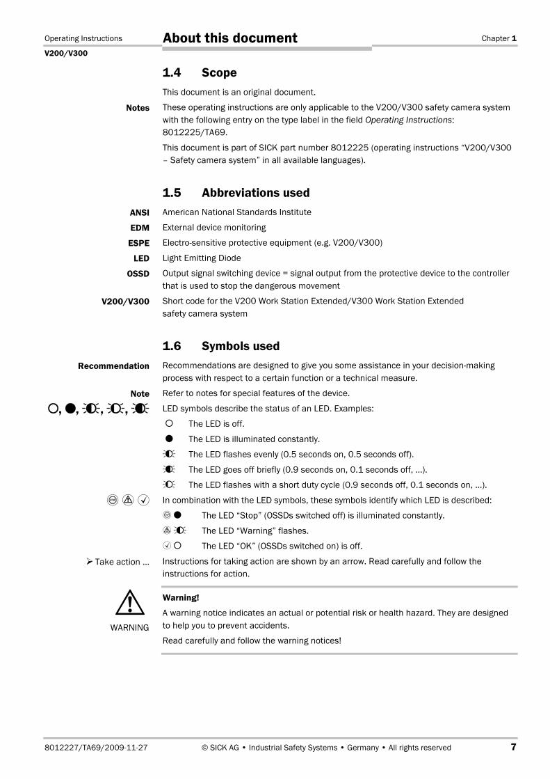
1.6 Symbols used
Recommendations are designed to give you some assistance in your decision-making
process with respect to a certain function or a technical measure.
Refer to notes for special features of the device.
LED symbols describe the status of an LED. Examples:
� The LED is off.
� The LED is illuminated constantly.
��� The LED flashes evenly (0.5 seconds on, 0.5 seconds off).
��� The LED goes off briefly (0.9 seconds on, 0.1 seconds off, …).
�� The LED flashes with a short duty cycle (0.9 seconds off, 0.1 seconds on, …).
In combination with the LED symbols, these symbols identify which LED is described:
� The LED “Stop” (OSSDs switched off) is illuminated constantly.
� ��� The LED “Warning” flashes.
�� The LED “OK” (OSSDs switched on) is off.
Instructions for taking action are shown by an arrow. Read carefully and follow the
instructions for action.
Warning!
A warning notice indicates an actual or potential risk or health hazard. They are designed
to help you to prevent accidents.
Read carefully and follow the warning notices!
Notes
ANSI
EDM
ESPE
LED
OSSD
V200/V300
Recommendation
Note
�,�, ���, ��, ���
��
Take action …
�WARNING
Chapter 1 Operating Instructions
V200/V300
8 © SICK AG • Industrial Safety Systems • Germany • All rights reserved 8012227/TA69/2009-11-27
About this document
The term “dangerous state”
The dangerous state (standard term) of the machine is always shown in the drawings and
diagrams of this document as a movement of a machine part. In practical operation, there
may be a number of different dangerous states:
� machine movements
� electrical conductors
� visible or invisible radiation
� a combination of several risks and hazards

Operating Instructions Chapter 2
V200/V300
8012227/TA69/2009-11-27 © SICK AG • Industrial Safety Systems • Germany • All rights reserved 9
On safety
2 On safety
This chapter deals with your own safety and the safety of the equipment operators.
� Please read this chapter carefully before working with the V200/V300 or with the
machine protected by the V200/V300.
2.1 Qualified safety personnel
The V200/V300 safety camera system must only be installed, commissioned and serviced
by qualified safety personnel. Qualified safety personnel are defined as persons who
� due to their specialist training and experience have adequate knowledge of the power-
driven equipment to be checked
and
� have been instructed by the responsible machine owner in the operation of the machine
and the current valid safety guidelines
and
� are sufficiently familiar with the applicable official health and work safety regulations,
directives and generally recognized engineering practice (e.g. DIN standards, VDE
stipulations, engineering regulations from other EC member states) that they can
assess the work safety aspects of the power-driven equipment
and
� have access to these operating instructions and have read them.
As a rule these are qualified safety personnel from the ESPE manufacturer or also persons
who have been appropriately trained at the ESPE manufacturer, are primarily involved in
checking ESPE and are allocated the task by the organisation operating the ESPE.

Chapter 2 Operating Instructions
V200/V300
10 © SICK AG • Industrial Safety Systems • Germany • All rights reserved 8012227/TA69/2009-11-27
On safety
2.2 Applications of the device
The V200/V300 safety camera system is an item of electro-sensitive protective equipment
(ESPE).
The V200/V300 safety camera system can be operated with 3 resolutions. Depending on
the resolution used, the maximum protective field dimensions change:
Protective field dimensions [m]Resolution
[mm] Minimum Maximum Note
20 0.40 × 0.40 1.00 × 1.00
24 0.40 × 0.40 1.20 × 1.20
30 0.60 × 0.60 1.50 × 1.50
On sizing the protective field the
ratio for the lengths of the sides
must be considered (see section 4.1
“Checking the dimensions of the
protective field” on page19 ff.)
The device is a Type 3 ESPE (V300 Work Station Extended) or a Type 2 (V200 Work Station
Extended) according to EN 61�4961 and IEC/TR 61�4964 and is therefore allowed for use
with controls in category 3 according to EN ISO 13�8491. The device is suitable for
hazardous point protection (hand protection).
Access to the hazardous point must be allowed only through the protective field. As long as
the hazardous point is occupied, the system must not start. Refer to section 3.3
“Application examples” on page 14 for an illustration of the protection modes.
Only use the safety camera system as an indirect protective measure!
An opto-electronic protective device provides indirect protection, e.g. by switching off the
power at the source of the hazard. It cannot provide protection from parts thrown out, nor
from emitted radiation. Transparent objects are not detected.
Depending on the application, mechanical guards may be required in addition to the safety
camera system.
The safety camera system is only intended for use in industrial environments. When used
in residential areas it can cause radio interferences.
2.3 Correct use
The V200/V300 safety camera system must be used only as defined in section 2.2
“Applications of the device”. It must be used only by qualified personnel and only on the
machine where it has been installed and initialised by qualified safety personnel in
accordance with these operating instructions.
If the device is used for any other purposes or modified in any way — also during mounting
and installation — any warranty claim against SICK AG shall become void.
Tab. 1: Maximum protective
field dimensions as a
function of the resolution
�WARNING
Operating Instructions Chapter 2
V200/V300
8012227/TA69/2009-11-27 © SICK AG • Industrial Safety Systems • Germany • All rights reserved 11
On safety
2.4 General safety notes and protective measures
Pay attention to the safety notes!
Please observe the following procedures in order to ensure the correct and safe use of the
V200/V300 safety camera system.
� The national/international rules and regulations apply to the installation, use and
periodic technical inspections of the safety camera system, in particular:
– Machinery Directive 2006/42/EC
– Work Equipment Directive 89/655/EEC
– the work safety regulations/safety rules
– other relevant safety regulations
Manufacturers and operators of the machine on which the safety camera system is used
are responsible for obtaining and observing all applicable safety regulations and rules.
� The notices, in particular the test regulations (see section 7.1 “Test notes” on page 44)
of these operating instructions (e.g. on use, mounting, installation or integration into the
existing machine controller) must be observed.
� The tests must be carried out by qualified safety personnel or specially qualified and
authorised personnel and must be recorded and documented to ensure that the tests
can be reconstructed and retraced at any time.
� Changes to the configuration of the devices can degrade the protective function. After
every change to the configuration you must therefore check the effectiveness of the
protective device. The person who makes the change is also responsible for the correct
protective function of the device.
� The light beams from the camera may be deflected by reflective surfaces. This can
result in failure to identify an object. For this reason reflective surfaces on the reflective
tape or in the protective field are not allowed.
� The operating instructions must be made available to the operator of the machine where
the V200/V300 safety camera system is fitted. The machine operator is to be instructed
in the use of the device by qualified safety personnel and must be instructed to read the
operating instructions.
� To meet the requirements of the relevant product standards (e.g. EN 61�4961), the
external voltage supply for the devices (SELV) must be able to bridge a brief mains
failure of 20 ms. Power supplies according to EN 60�2041 satisfy this requirement.
Suitable power supplies are available as accessories from SICK (see section 12.2
“Accessories” on page61).
�WARNING

Chapter 2 Operating Instructions
V200/V300
12 © SICK AG • Industrial Safety Systems • Germany • All rights reserved 8012227/TA69/2009-11-27
On safety
2.5 Environmental protection
The V200/V300 safety camera system has been designed to minimise environmental
impact. It uses only a minimum of power and natural resources.
� At work, always act in an environmentally responsible manner.
2.5.1 Disposal
� Always dispose of unserviceable or irreparable devices in compliance with local/
national rules and regulations with respect to waste disposal (e.g. European waste
code 16 02 14).
We would be pleased to be of assistance to you on the disposal of these devices.
Contact us.
2.5.2 Separation of materials
Only qualified safety personnel are allowed to separate materials!
Caution is required when dismantling devices. There is a risk of injuries.
Before you send the devices for appropriate recycling, it is necessary to separate the
different materials in the V200/V300.
� Separate the housing from the rest of the parts (in particular the circuit board).
� Send the separated parts for recycling as appropriate:
Components Disposal
Product
Housing Metal recycling (aluminium)
Circuit boards, cable, connector and
electrical connecting pieces
Electronic recycling
Packaging
Cardboard, paper Paper/cardboard recycling
Polyethylene packaging Plastic recycling
Note
�WARNING
Tab. 2: Overview on disposal
by components

Operating Instructions Chapter 3
V200/V300
8012227/TA69/2009-11-27 © SICK AG • Industrial Safety Systems • Germany • All rights reserved 13
Product description
3 Product description
This chapter provides information on the special features and properties of the
V200/V300 safety camera system. It describes the construction and the operating
principle of the device, in particular the different operating modes.
� Please read this chapter before mounting, installing and commissioning the device.
3.1 Special features
� V200 Work Station Extended: Type 2 ESPE according to EN 61�4961
� V300 Work Station Extended: Type 3 ESPE according to EN 61�4961
complies with the requirements for the “Control reliable” safety level.
� protective operation with either internal or external (realised on the machine)
restart interlock
� facility for connecting a reset button
� facility for connecting an external device monitoring (EDM)
� status indication by LED
3.2 Operating principle of the device
The V200/V300 safety camera system comprises a camera as well as a reflective tape
with which the contour to be monitored is defined.
The camera monitors the area bounded by its field of view and the reflective tape – the
protective field – for interruptions. If the V200/V300 detects an interruption in the shape
of the protective field, the camera shuts down its safe outputs.
Please refer to chapter 11 “Technical specifications” on page 54 for the data sheet.
Please refer to page 58 for the dimensional drawings.
Fig. 1: Operating principle
of the V200/V300
Camera
Reflective tape on the
members opposite thecamera
Protective field
Machine-side mountingprofile

Chapter 3 Operating Instructions
V200/V300
14 © SICK AG • Industrial Safety Systems • Germany • All rights reserved 8012227/TA69/2009-11-27
Product description
3.3 Application examples
The mounting of the device is only shown schematically in the following figures for reasons
of simplicity.
For correct mounting, pay attention to the notes in chapter 4 “Mounting” on page 19.
The V200/V300 safety camera system operates correctly as a protective device only if the
following conditions are met:
� The control of the machine must be electrical.
� It must be possible to achieve a safe state on the machine at any time.
� Camera and reflective tape must be so mounted that objects penetrating into the
hazardous area are safely identified by the V200/V300.
� The reset button must be fitted outside the hazardous area such that it cannot be
operated by a person working inside the hazardous area. When operating the reset
button, the operator must have full visual command of the hazardous area.
� The statutory and local rules and regulations must be observed when installing and
using the device.
� The necessary protective field dimensions must not exceed the permitted ratio for the
lengths of the sides (see section 4.1 “Checking the dimensions of the protective field”
on page 19).
Note
Fig. 2: Hazardous point pro-
tection with one V200/V300,
mounting in the frame
(left figure)
Fig. 3: Hazardous point pro-
tection with one V200/V300,
mounting on the frame
(right figure)
Fig. 4: Hazardous point pro-
tection with two V200/V300,
placement in opposite
directions (left figure)
Fig. 5: Hazardous point pro-
tection with two V200/V300,
placement at corner
(right figure)

Operating Instructions Chapter 3
V200/V300
8012227/TA69/2009-11-27 © SICK AG • Industrial Safety Systems • Germany • All rights reserved 15
Product description
3.4 Configurable functions
This section describes the functions of the V200/V300 safety camera system that can be
configured.
Test the protective device after any changes!
After each modification to the protective device or its connection, you must check the
whole protective device for effectiveness (see section 7.1 “Test notes” on page 44).
3.4.1 Restart interlock
The V200/V300 has an internal restart interlock. The dangerous state of the machine (�)
is interrupted on a protective field interruption (�), and is not re-enabled (�) until the
operator presses the reset button.
� If you use the V200/V300 without internal restart interlock, then you must implement
the restart interlock externally, i.e. machine-side.
� Do not confuse the restart interlock with the starting interlock on the machine. The
starting interlock prevents the machine starting after switching on. The restart interlock
prevents the machine starting again after an error or an interruption of the light path.
When using the V200/V300, you can implement the restart interlock in two different ways:
� with the internal restart interlock of the V200/V300:
The V200/V300 controls the restart.
� with the restart interlock of the machine (external):
The V200/V300 has no control over the restart.
�WARNING
Fig. 6: Outline drawing of the
protective operation
Notes
Chapter 3 Operating Instructions
V200/V300
16 © SICK AG • Industrial Safety Systems • Germany • All rights reserved 8012227/TA69/2009-11-27
Product description
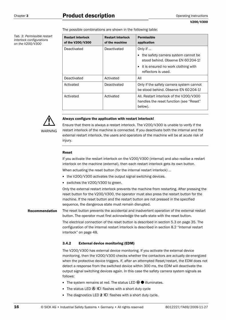
The possible combinations are shown in the following table:
Restart interlock
of the V200/V300
Restart interlock
of the machine
Permissible
application
Deactivated Deactivated Only if …
� the safety camera system cannot be
stood behind. Observe EN 60�2041!
� it is ensured no work clothing with
reflectors is used.
Deactivated Activated All
Activated Deactivated Only if the safety camera system cannot
be stood behind. Observe EN 60�2041!
Activated Activated All. Restart interlock of the V200/V300
handles the reset function (see “Reset”
below).
Always configure the application with restart interlock!
Ensure that there is always a restart interlock. The V200/V300 is unable to verify if the
restart interlock of the machine is connected. If you deactivate both the internal and the
external restart interlock, the users and operators of the machine will be at acute risk of
injury.
Reset
If you activate the restart interlock on the V200/V300 (internal) and also realise a restart
interlock on the machine (external), then each restart interlock gets its own button.
When actuating the reset button (for the internal restart interlock) …
� the V200/V300 activates the output signal switching devices.
� switches the V200/V300 to green.
Only the external restart interlock prevents the machine from restarting. After pressing the
reset button for the V200/V300, the operator must also press the restart button for the
machine. If the reset button and the restart button are not pressed in the specified
sequence, the dangerous state must remain disrupted.
The reset button prevents the accidental and inadvertent operation of the external restart
button. The operator must first acknowledge the safe state with the reset button.
The electrical connection of the reset button is described in section 5.3 on page 35. The
configuration of the internal restart interlock is described in section 8.2 “Internal restart
interlock” on page 48.
3.4.2 External device monitoring (EDM)
The V200/V300 has external device monitoring. If you activate the external device
monitoring, then the V200/V300 checks whether the contactors are actually de-energized
when the protective device triggers. If, after an attempted Reset/restart, the EDM does not
detect a response from the switched device within 300 ms, the EDM will deactivate the
output signal switching devices again. In this case the safety camera system signals as
follows:
� The system remains at red. The status LED � illuminates.
� The status LED � �� flashes with a short duty cycle
� The diagnostics LED 2 �� flashes with a short duty cycle.
Tab. 3: Permissible restart
interlock configurations
on the V200/V300
�WARNING
Recommendation
Operating Instructions Chapter 3
V200/V300
8012227/TA69/2009-11-27 © SICK AG • Industrial Safety Systems • Germany • All rights reserved 17
Product description
If the system is unable to change to a safe operational state (e.g. after contactor failure),
the system locks and shuts down completely (“lockout”, see page 52). The electrical
connection for the external device monitoring is described in section 5.3 on page 35. The
configuration of the external device monitoring is described in chapter 8 “Configuration”
on page 46.
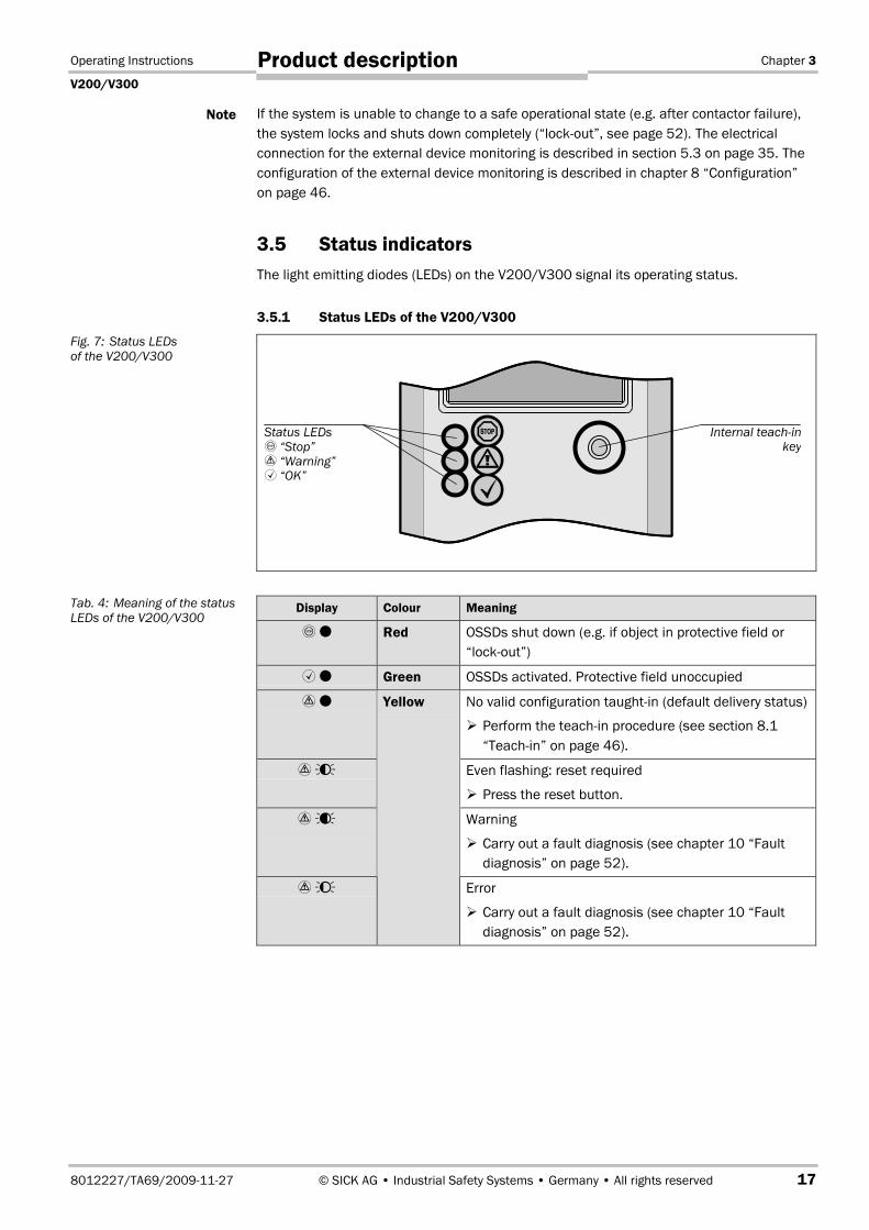
3.5 Status indicators
The light emitting diodes (LEDs) on the V200/V300 signal its operating status.
3.5.1 Status LEDs of the V200/V300
Display Colour Meaning
� Red OSSDs shut down (e.g. if object in protective field or
“lockout”)
�� Green OSSDs activated. Protective field unoccupied
�� No valid configuration taught-in (default delivery status)
� Perform the teach-in procedure (see section 8.1
“Teach-in” on page 46).
� ��� Even flashing: reset required
� Press the reset button.
� ��� Warning
� Carry out a fault diagnosis (see chapter 10 “Fault
diagnosis” on page 52).
� ��
Yellow
Error
� Carry out a fault diagnosis (see chapter 10 “Fault
diagnosis” on page 52).
Note
Fig. 7: Status LEDs
of the V200/V300
Tab. 4: Meaning of the status
LEDs of the V200/V300
Status LEDs
“Stop”
� “Warning”� “OK”
Internal teach-inkey
Chapter 3 Operating Instructions
V200/V300
18 © SICK AG • Industrial Safety Systems • Germany • All rights reserved 8012227/TA69/2009-11-27
Product description
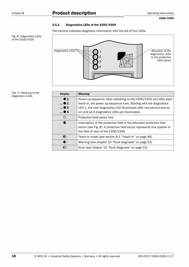
3.5.2 Diagnostics LEDs of the V200/V300
The camera indicates diagnostic information with the aid of four LEDs.
Display Meaning
� 1
… � 2
… � 3
… � 4
Power-up sequence: After switching on the V200/V300 and after each
teach-in, the power up sequence runs. Starting with the diagnostics
LED 1, the next diagnostics LED illuminates after one second and so
on until all 4 diagnostics LEDs are illuminated.
� Protective field sector free
� Interruption of the protective field in the allocated protective field
sector (see Fig. 8). A protective field sector represents one quarter of
the field of view of the V200/V300.
��� Teach-in mode (see section 8.1 “Teach-in” on page 46)
��� Warning (see chapter 10 “Fault diagnosis” on page 52)
�� Error (see chapter 10 “Fault diagnosis” on page 52)
Fig. 8: Diagnostics LEDs
of the V200/V300
Tab. 5: Meaning of the
diagnostics LEDs
Diagnostics LEDs Allocation of the
diagnostics LEDs
to the protectivefield sector
Operating Instructions Chapter 4
V200/V300
8012227/TA69/2009-11-27 © SICK AG • Industrial Safety Systems • Germany • All rights reserved 19
Mounting
4 Mounting
This chapter describes the preparation and completion of the mounting of the V200/V300
safety camera system. Mounting requires the following steps:
� checking the dimensions of the protective field (see below)
� determining the safety distance (see page 21)
� mounting of the camera (see page 25)
� mounting the reflective tape (see page 30)
The following steps are necessary after mounting:
� completing the electrical connections (see chapter 5 on page 33)
� testing the installation (see section 7.1 on page 44)
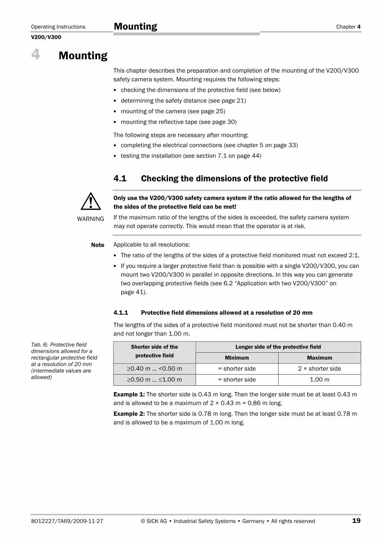
4.1 Checking the dimensions of the protective field
Only use the V200/V300 safety camera system if the ratio allowed for the lengths of
the sides of the protective field can be met!
If the maximum ratio of the lengths of the sides is exceeded, the safety camera system
may not operate correctly. This would mean that the operator is at risk.
Applicable to all resolutions:
� The ratio of the lengths of the sides of a protective field monitored must not exceed 2:1.
� If you require a larger protective field than is possible with a single V200/V300, you can
mount two V200/V300 in parallel in opposite directions. In this way you can generate
two overlapping protective fields (see 6.2 “Application with two V200/V300” on
page 41).
4.1.1 Protective field dimensions allowed at a resolution of 20 mm
The lengths of the sides of a protective field monitored must not be shorter than 0.40 m
and not longer than 1.00 m.
Longer side of the protective fieldShorter side of the
protective field Minimum Maximum
≥0.40 m … <0.50 m = shorter side 2 × shorter side
≥0.50 m … ≤1.00 m = shorter side 1.00 m
Example 1: The shorter side is 0.43 m long. Then the longer side must be at least 0.43 m
and is allowed to be a maximum of 2 × 0.43 m = 0.86 m long.
Example 2: The shorter side is 0.78 m long. Then the longer side must be at least 0.78 m
and is allowed to be a maximum of 1.00 m long.
�WARNING
Note
Tab. 6: Protective field
dimensions allowed for a
rectangular protective field
at a resolution of 20 mm
(intermediate values are
allowed)

Chapter 4 Operating Instructions
V200/V300
20 © SICK AG • Industrial Safety Systems • Germany • All rights reserved 8012227/TA69/2009-11-27
Mounting
4.1.2 Protective field dimensions allowed at a resolution of 24 mm
The lengths of the sides of a protective field monitored must not be shorter than 0.40 m
and not longer than 1.20 m.
Longer side of the protective fieldShorter side of the
protective field Minimum Maximum
≥0.40 m … <0.60 m = shorter side 2 × shorter side
≥0.60 m … ≤1.20 m = shorter side 1.20 m
Example 1: The shorter side is 0.43 m long. Then the longer side must be at least 0.43 m
and is allowed to be a maximum of 2 × 0.43 m = 0.86 m long.
Example 2: The shorter side is 0.78 m long. Then the longer side must be at least 0.78 m
and is allowed to be a maximum of 1.20 m long.
4.1.3 Protective field dimensions allowed at a resolution of 30 mm
The lengths of the sides of a protective field monitored must not be shorter than 0.60 m
and not longer than 1.50 m.
Longer side of the protective fieldShorter side of the
protective field Minimum Maximum
≥0.60 m … <0.75 m = shorter side 2 × shorter side
≥0.75 m … ≤1.50 m = shorter side 1.50 m
Example 1: The shorter side is 0.63 m long. Then the longer side must be at least 0.63 m
and is allowed to be a maximum of 2 × 0.63 m = 1.26 m long.
Example 2: The shorter side is 0.78 m long. Then the longer side must be at least 0.78 m
and is allowed to be a maximum of 1.50 m long.
Tab. 7: Protective field
dimensions allowed for a
rectangular protective field
at a resolution of 24 mm
(intermediate values are
allowed)
Tab. 8: Protective field
dimensions allowed for a
rectangular protective field
at a resolution of 30 mm
(intermediate values are
allowed)
Operating Instructions Chapter 4
V200/V300
8012227/TA69/2009-11-27 © SICK AG • Industrial Safety Systems • Germany • All rights reserved 21
Mounting
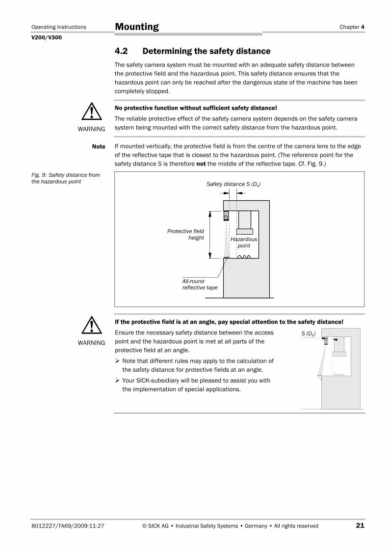
4.2 Determining the safety distance
The safety camera system must be mounted with an adequate safety distance between
the protective field and the hazardous point. This safety distance ensures that the
hazardous point can only be reached after the dangerous state of the machine has been
completely stopped.
No protective function without sufficient safety distance!
The reliable protective effect of the safety camera system depends on the safety camera
system being mounted with the correct safety distance from the hazardous point.
If mounted vertically, the protective field is from the centre of the camera lens to the edge
of the reflective tape that is closest to the hazardous point. (The reference point for the
safety distance S is therefore not the middle of the reflective tape. Cf. Fig. 9.)
If the protective field is at an angle, pay special attention to the safety distance!
Ensure the necessary safety distance between the access
point and the hazardous point is met at all parts of the
protective field at an angle.
� Note that different rules may apply to the calculation of
the safety distance for protective fields at an angle.
� Your SICK-subsidiary will be pleased to assist you with
the implementation of special applications.
�WARNING
Note
Fig. 9: Safety distance from
the hazardous point
�WARNING
Hazardouspoint
Safety distance S (Ds)
Protective field
height
All-roundreflective tape
S (Ds)
Chapter 4 Operating Instructions
V200/V300
22 © SICK AG • Industrial Safety Systems • Germany • All rights reserved 8012227/TA69/2009-11-27
Mounting
4.2.1 Safety distance according to prEN ISO 13�855 and EN ISO 13�857
The safety distance as defined in prEN ISO 13�855 and EN ISO 13�857 depends on:
� stopping/run-down time of the machine or system
(The stopping/run-down time is shown in the machine documentation or must be
determined by taking a measurement.)
� response time of the entire protective device (V200/V300: 20 ms)
� reach or approach speed
� other parameters that are stipulated by the standard depending on the application
How to calculate the minimum safety distance S according to prEN ISO 13�855 and
EN ISO 13�857:
The following calculation shows an example calculation of the safety distance. The
calculation is based on the assumption that the approach is perpendicular to the
protective field.
Depending on the application and the ambient conditions, a different calculation may be
necessary.
� Initial formula: S = K × T + 8 × (d – 14)
Where …
S = Safety distance in [mm]
K = 2000 mm/s
Definition and value as per prEN ISO 13�855, derived from data on the approach
speed of the body or parts of the body
T = Stopping/run-down time of the entire system in [s]
Stopping/run-down time of the entire system = Stopping/run-down time of the
machine + response time of the protective device after light path interruption
d = Detection capability (resolution) of the protective device in [mm]
The reach/approach speed is already included in the calculation formula.
With K = 2000 mm/s the 1st formula is:
1. calculation formula: S = 2000 × T + 8 × (d – 14)
� If the result S is ≥ 100 mm and S ≤ 500 mm, then use the determined value as the
safety distance.
As per prEN ISO 13�855 a safety distance S < 100 mm is not allowed. If you obtain a
value S < 100 mm with your calculation, please contact SICK service.
� If the result is S > 500 mm, use K = 1600 mm/s in the formula and calculate S again:
2. calculation formula: S = 1600 × T + 8 × (d – 14)
� If the new value S is > 500 mm, then use the newly determined value as the minimum
safety distance.
If the new value S is ≤ 500 mm, then use 500 mm as the minimum safety distance.
Example:
The following values apply:
Stopping/run-down time of the machine = 290 ms
Response time of the V200/V300 after light path interruption = 20 ms
Detection capability (resolution) d of the V200/V300 = 20 mm
You will find the values for the response time and the resolution of the V200/V300 in
chapter 11 “Technical specifications” on page 54.
Note
Note
Note
Operating Instructions Chapter 4
V200/V300
8012227/TA69/2009-11-27 © SICK AG • Industrial Safety Systems • Germany • All rights reserved 23
Mounting
Minimum safety distance calculation:
� Step 1: Calculation of the stopping/run-down time of the entire system:
T = 290 ms + 20 ms = 310 ms = 0.31 s
� Step 2: Insert the values in the 1st formula (S = 2000 × T + 8 × (d – 14)):
S = 2000 × 0.31 + 8 × (20 – 14) = 668 mm
� Step 3: Check the value for S.
S > 500 mm. For this reason the 2nd formula must be used.
� Step 4: Insert the values in the 2nd formula (S = 1600 × T + 8 × (d – 14)):
S = 1600 × 0.31 + 8 × (20 – 14) = 544 mm
� Step 5: Check the value of S.
S > 500 mm. For this reason 544 mm must be used as the minimum safety distance.
Chapter 4 Operating Instructions
V200/V300
24 © SICK AG • Industrial Safety Systems • Germany • All rights reserved 8012227/TA69/2009-11-27
Mounting
4.2.2 Safety distance if OSHA and ANSI are applicable1)
If OSHA and ANSI are applicable, the safety distance depends on:
� stopping/run-down time of the machine or system
(The stopping/run-down time is shown in the machine documentation or must be
determined by taking a measurement.)
� response time of the entire protective device (V200/V300: 20 ms)
� reach or approach speed
� other parameters that are stipulated by the standard depending on the application
How to calculate the safety distance Ds if OSHA and ANSI are applicable1)
:
The following calculation shows an example calculation of the safety distance. Depending
on the application and the ambient conditions, a different calculation may be necessary.
� Calculate Ds using the following formula:
Ds = Hs × (Ts + Tc + Tr + Tbm) + Dpf
Where …
Ds = The minimum distance in inches (or millimetres) from the hazardous point to the
protective device
Hs = A parameter in inches/second or millimetres/second, derived from data on
approach speeds of the body or parts of the body. Often 63 inches/second
(1600 mm/second) is used for Hs.
Ts = Stopping/run down time of the machine tool measured at the final control
element
Tc = Stopping/run-down time of the control system
Tr = Response time of the entire protective device after light path interruption
(V200/V300: 20 ms)
Tbm = Additional response time allowed for brake monitor to compensate for wear
Any additional response times must be accounted for in this calculation.
Dpf = An additional distance added to the overall safety distance required. This value is
based on intrusion toward the hazardous point prior to actuation of the electro-
sensitive protective equipment (ESPE). Values range from 0.25 inches to 48
inches (6 to 1220 millimetres) or more depending on application.
Example:
For vertical protection with an opto-electronic protective device with an effective
resolution finer than 2.5 inches (64 millimetres), Dpf can be determined
approximately using the following formula:
Dpf (inches) = 3.4 × (effective resolution – 0.276), but not less than 0.
1)Safety distance according to ANSI B11.19:200304, Annex D and Code of Federal Regulations, Volume 29,
Part 1910.217 … (h) (9) (v).
Note
Note
Operating Instructions Chapter 4
V200/V300
8012227/TA69/2009-11-27 © SICK AG • Industrial Safety Systems • Germany • All rights reserved 25
Mounting
4.3 Avoiding unmonitored areas
Provide separate protection for unmonitored areas!
During the installation of the V200/V300 safety camera system, incorrect mounting or
mutual interference between several systems may result in areas that are not monitored
and through which an operator could reach the hazardous point.
� Protect unmonitored areas using mechanical guards.
� Note the following warning and precautions to prevent unmonitored areas!
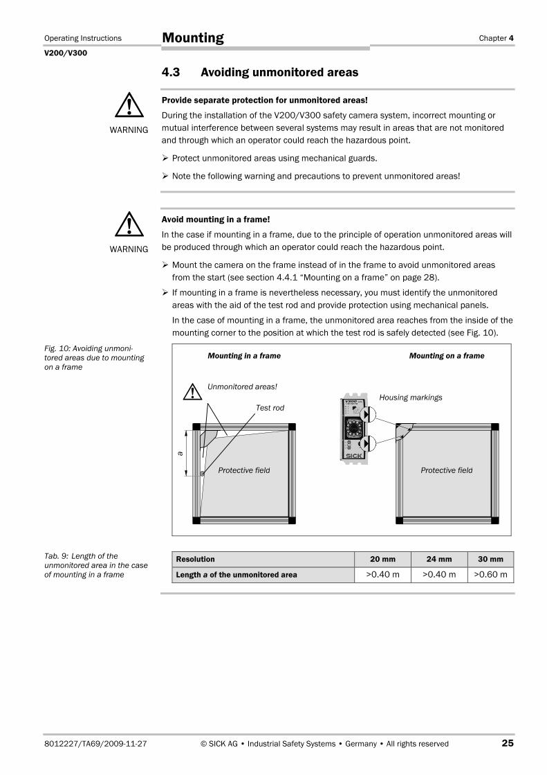
Avoid mounting in a frame!
In the case if mounting in a frame, due to the principle of operation unmonitored areas will
be produced through which an operator could reach the hazardous point.
� Mount the camera on the frame instead of in the frame to avoid unmonitored areas
from the start (see section 4.4.1 “Mounting on a frame” on page 28).
� If mounting in a frame is nevertheless necessary, you must identify the unmonitored
areas with the aid of the test rod and provide protection using mechanical panels.
In the case of mounting in a frame, the unmonitored area reaches from the inside of the
mounting corner to the position at which the test rod is safely detected (see Fig. 10).
Resolution 20 mm 24 mm 30 mm
Length a of the unmonitored area >0.40 m >0.40 m >0.60 m
�WARNING
�WARNING
Fig. 10: Avoiding unmoni-
tored areas due to mounting
on a frame
Tab. 9: Length of the
unmonitored area in the case
of mounting in a frame
�Unmonitored areas!
Test rod
a
Housing markings
Protective fieldProtective field
Mounting on a frameMounting in a frame
Chapter 4 Operating Instructions
V200/V300
26 © SICK AG • Industrial Safety Systems • Germany • All rights reserved 8012227/TA69/2009-11-27
Mounting
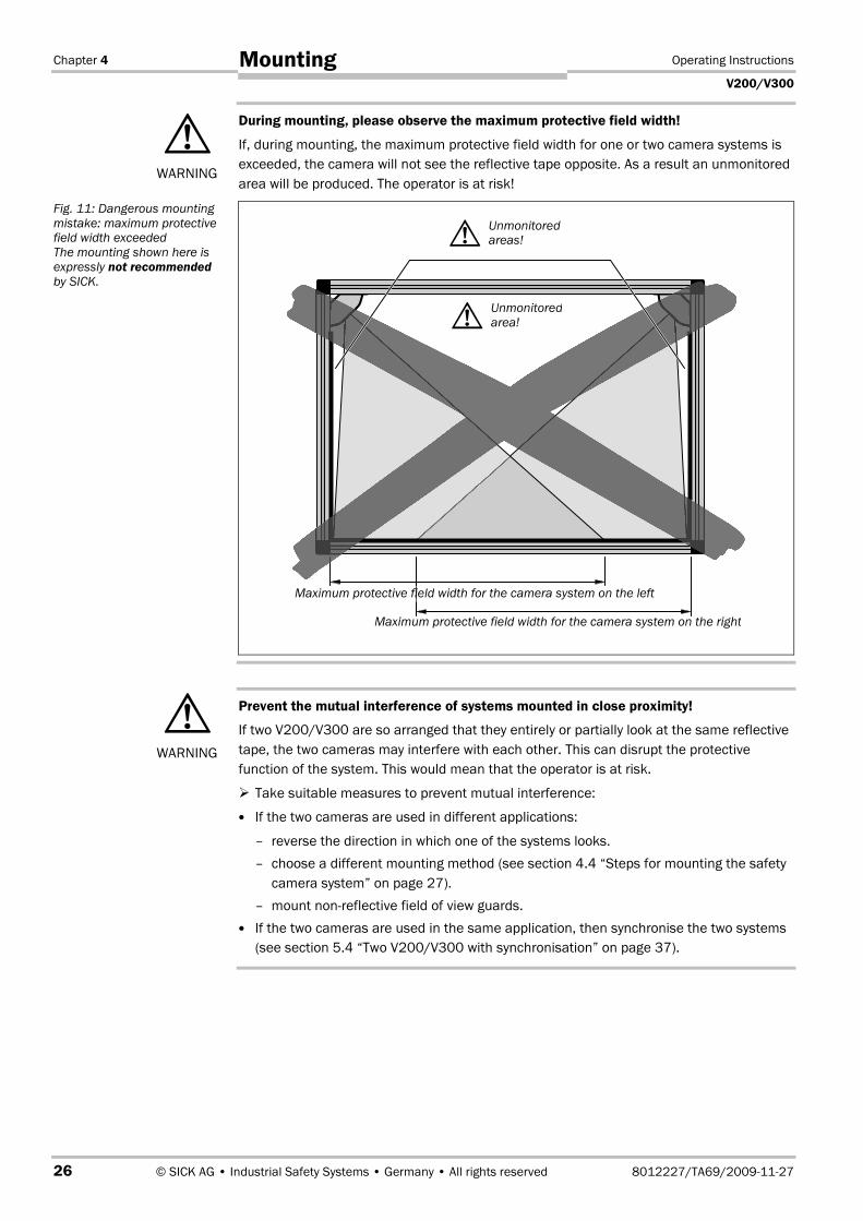
During mounting, please observe the maximum protective field width!
If, during mounting, the maximum protective field width for one or two camera systems is
exceeded, the camera will not see the reflective tape opposite. As a result an unmonitored
area will be produced. The operator is at risk!
Prevent the mutual interference of systems mounted in close proximity!
If two V200/V300 are so arranged that they entirely or partially look at the same reflective
tape, the two cameras may interfere with each other. This can disrupt the protective
function of the system. This would mean that the operator is at risk.
� Take suitable measures to prevent mutual interference:
� If the two cameras are used in different applications:
– reverse the direction in which one of the systems looks.
– choose a different mounting method (see section 4.4 “Steps for mounting the safety
camera system” on page 27).
– mount non-reflective field of view guards.
� If the two cameras are used in the same application, then synchronise the two systems
(see section 5.4 “Two V200/V300 with synchronisation” on page 37).
�WARNING
Fig. 11: Dangerous mounting
mistake: maximum protective
field width exceeded
The mounting shown here is
expressly not recommended
by SICK.
�WARNING
�Unmonitored
areas!
�Unmonitored
area!
Maximum protective field width for the camera system on the left
Maximum protective field width for the camera system on the right
Operating Instructions Chapter 4
V200/V300
8012227/TA69/2009-11-27 © SICK AG • Industrial Safety Systems • Germany • All rights reserved 27
Mounting
4.4 Steps for mounting the safety camera system
Special features to note during mounting:
� Avoid unmonitored areas as described in the previous section.
� Always mount the camera on a flat surface.
� Always mount the camera on a metal surface and ensure good mechanical contact. In
this way you will ensure adequate heat dissipation from the device.
� During mounting, ensure that camera and reflective tape are aligned correctly. The
V200/V300 accepts a defined lateral tolerance (see section 4.4.3 “Mounting the
reflective tape” on page 30).
� Take suitable measures to attenuate vibration if the shock requirements are above the
values given in section 11.1 “Data sheet” on page 54.
� Observe the safety distance of the system during mounting. On this subject read
section 4.2 “Determining the safety distance” on page 21.
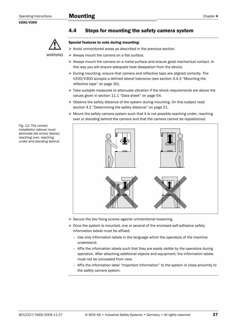
� Mount the safety camera system such that it is not possible reaching under, reaching
over or standing behind the camera and that the camera cannot be repositioned.
� Secure the two fixing screws against unintentional loosening.
� Once the system is mounted, one or several of the enclosed self-adhesive safety
information labels must be affixed:
– Use only information labels in the language which the operators of the machine
understand.
– Affix the information labels such that they are easily visible by the operators during
operation. After attaching additional objects and equipment, the information labels
must not be concealed from view.
– Affix the information label “Important Information” to the system in close proximity to
the safety camera system.
�WARNING
Fig. 12: The correct
installation (above) must
eliminate the errors (below)
reaching over, reaching
under and standing behind.
Chapter 4 Operating Instructions
V200/V300
28 © SICK AG • Industrial Safety Systems • Germany • All rights reserved 8012227/TA69/2009-11-27
Mounting
The most common mounting options are:
� mounting on a frame
� mounting in a frame
You will find other mounting options on the example application at www.sick.com.
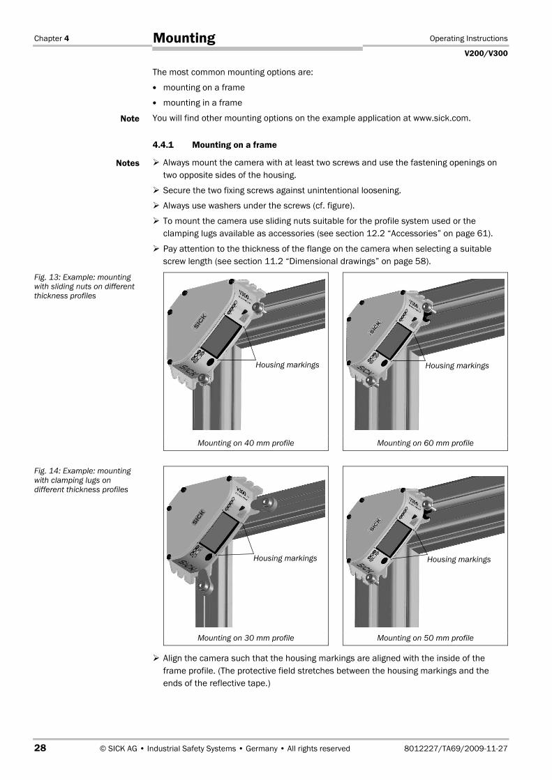
4.4.1 Mounting on a frame
� Always mount the camera with at least two screws and use the fastening openings on
two opposite sides of the housing.
� Secure the two fixing screws against unintentional loosening.
� Always use washers under the screws (cf. figure).
� To mount the camera use sliding nuts suitable for the profile system used or the
clamping lugs available as accessories (see section 12.2 “Accessories” on page 61).
� Pay attention to the thickness of the flange on the camera when selecting a suitable
screw length (see section 11.2 “Dimensional drawings” on page 58).
Mounting on 40 mm profile Mounting on 60 mm profile
Mounting on 30 mm profile Mounting on 50 mm profile
� Align the camera such that the housing markings are aligned with the inside of the
frame profile. (The protective field stretches between the housing markings and the
ends of the reflective tape.)
Note
Notes
Fig. 13: Example: mounting
with sliding nuts on different
thickness profiles
Fig. 14: Example: mounting
with clamping lugs on
different thickness profiles
Housing markings Housing markings
Housing markings Housing markings
Operating Instructions Chapter 4
V200/V300
8012227/TA69/2009-11-27 © SICK AG • Industrial Safety Systems • Germany • All rights reserved 29
Mounting
4.4.2 Mounting in a frame
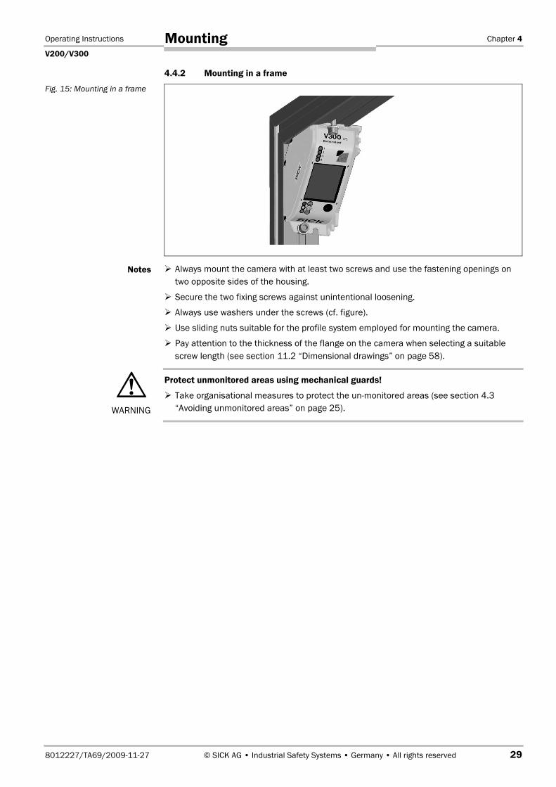
� Always mount the camera with at least two screws and use the fastening openings on
two opposite sides of the housing.
� Secure the two fixing screws against unintentional loosening.
� Always use washers under the screws (cf. figure).
� Use sliding nuts suitable for the profile system employed for mounting the camera.
� Pay attention to the thickness of the flange on the camera when selecting a suitable
screw length (see section 11.2 “Dimensional drawings” on page 58).
Protect unmonitored areas using mechanical guards!
� Take organisational measures to protect the un-monitored areas (see section 4.3
“Avoiding unmonitored areas” on page 25).
Fig. 15: Mounting in a frame
Notes
�WARNING

Chapter 4 Operating Instructions
V200/V300
30 © SICK AG • Industrial Safety Systems • Germany • All rights reserved 8012227/TA69/2009-11-27
Mounting
4.4.3 Mounting the reflective tape
Prior to mounting the reflective tape, pay attention to the following notes:
� Plan the attachment of the reflective tape exactly prior to bonding it in place. The
adhesive on the reflective tape is very resilient. It is not possible to remove the tape
again without destroying it. You will need a suitable solvent to remove the reflective
tape (see 12.2 “Accessories” on page 61).
� If you must bond the reflective tape in several sections, then ensure there are no gaps,
folds or offset at the joints. The reflective tape must run seamlessly along the contour to
be monitored.
Only the longest contiguous section of the reflective tape is taught-in by the
V200/V300. If there are gaps in the reflection, the safety camera system will ignore the
shorter section of the reflective tape.
� If damage to the reflective tape is to be expected due to the application, e.g. because
heavy or sharp-edged objects are to pushed over the working area, you should use one
of the following possible mounting methods:
– Mount the camera in the bottom of the frame.
– Mount the camera lower than the contact surface in front of the frame.
Notes
Fig. 16: Correct arrangement
of the reflective tapes at
joints

Operating Instructions Chapter 4
V200/V300
8012227/TA69/2009-11-27 © SICK AG • Industrial Safety Systems • Germany • All rights reserved 31
Mounting
How to mount the reflective tape:
The reflective tape is attached by simply bonding it in place.
� Clean the surface where the tape is to be attached so that it is clean of residue.
� Remove the protective film on the rear of the reflective tape and apply the tape
perpendicular to the camera’s optical axis. The camera will tolerate a small divergence
from the optical axis (cf. Fig. 17ff.).
Fig. 17: Permissible diver-
gence of the reflective tape
from the optical axis of the
camera as a function of the
distance at 20 mm resolution
(illustration of divergence not
to scale)
Fig. 18: Permissible diver-
gence of the reflective tape
from the optical axis of the
camera as a function of the
distance at 24 mm resolution
(illustration of divergence not
to scale)
V200/V300
Permissible divergence of the reflective tape [mm]
Dis
tan
ce
toth
ere
fle
cti
ve
tap
e[m
] Lateral tolerance
±9.2°
Permissible
applications
Reflective tape
Permissible divergence of the reflective tape [mm]
Dis
tan
ce
toth
ere
fle
cti
ve
tap
e[m
]
Lateral tolerance
±9.2°
Permissible
applications
Reflective tape
V200/V300
Chapter 4 Operating Instructions
V200/V300
32 © SICK AG • Industrial Safety Systems • Germany • All rights reserved 8012227/TA69/2009-11-27
Mounting
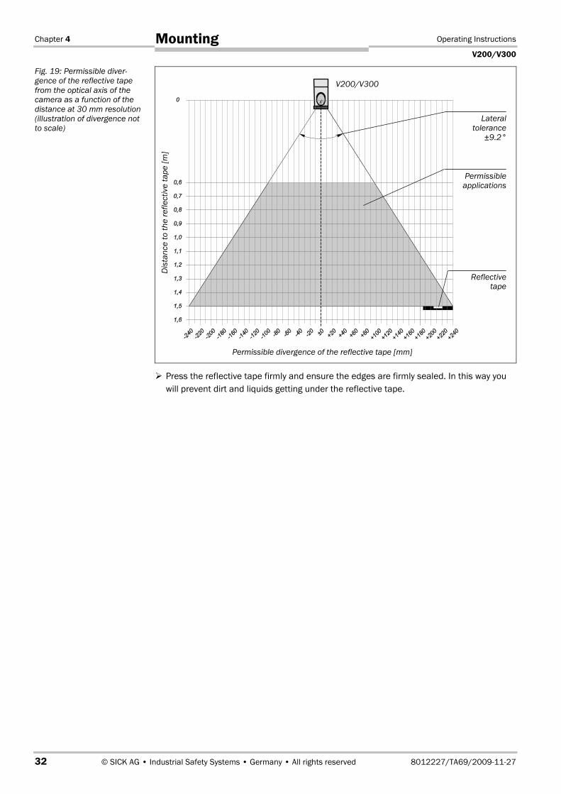
� Press the reflective tape firmly and ensure the edges are firmly sealed. In this way you
will prevent dirt and liquids getting under the reflective tape.
Fig. 19: Permissible diver-
gence of the reflective tape
from the optical axis of the
camera as a function of the
distance at 30 mm resolution
(illustration of divergence not
to scale)
V200/V300
Dis
tan
ce
toth
ere
fle
cti
ve
tap
e[m
]
Lateral
tolerance
±9.2°
Permissible
applications
Reflectivetape
Permissible divergence of the reflective tape [mm]

Operating Instructions Chapter 5
V200/V300
8012227/TA69/2009-11-27 © SICK AG • Industrial Safety Systems • Germany • All rights reserved 33
Electrical installation
5 Electrical installation
Switch the entire machine/system off line!
The machine/system could unintentionally start up while you are connecting the devices.
� Ensure that the entire machine/system is disconnected during the electrical
installation.
Connect OSSD1 and OSSD2 separately!
You are not allowed to connect OSSD1 and OSSD2 together, otherwise signal safety will
not be ensured.
� Ensure that the machine controller processes the two signals separately.
� Contactors connected in series must be positively guided and monitored (see
section 5.3 in “External device monitoring (EDM)” on page 36).
Only connect the OSSDs to a single subsequent switching element!
� Each output signal switching device (OSSD) is only allowed to be connected to one
switching element (e.g. relay or contactor). If several switching elements are required,
then you must choose a suitable form of contact duplication.
Prevent the occurrence of a potential difference between the loads and the protective
device!
� If you connect loads to the OSSDs that are not reverse polarity protected, then you must
connect the 0 V connections for these loads and the related protective device
separately, one after the other, to the same 0 V terminal strip. Only then is it ensured
that in the case of a fault, it is not possible for a potential difference to form between
the 0 V connections for the loads and the related protective device.
� The two outputs are protected against short-circuits to 24 V DC and 0 V. When the light
path is clear, the signal level on the outputs is HIGH DC (at potential), when the light
path is interrupted or there is a device fault the outputs are LOW DC.
� The V200/V300 safety camera system meets the interference suppression
requirements (EMC) for industrial use (interference suppression class A). When used in
residential areas it can cause radio interferences.
� To ensure full electromagnetic compatibility (EMC), functional earth (FE) must be
connected.
�WARNING
Notes
OS
SD
1
OS
SD
2
OS
SD
1
OS
SD
2
Chapter 5 Operating Instructions
V200/V300
34 © SICK AG • Industrial Safety Systems • Germany • All rights reserved 8012227/TA69/2009-11-27
Electrical installation
� To meet the requirements of the relevant product standards (e.g. EN 61�4961), the
external voltage supply for the devices (SELV) must be able to bridge a brief mains
failure of 20 ms. Power supplies according to EN 60�2041 satisfy this requirement.
Suitable power supplies are available as accessories from SICK (see section 12.2
“Accessories” on page 61).
� Dimension the electrical protection for the camera to suit the information in
section 11.1 “Data sheet” on page 54.
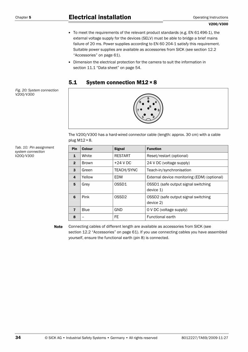
5.1 System connection M12�× 8
The V200/V300 has a hard-wired connector cable (length: approx. 30 cm) with a cable
plug M12�× 8.
Pin Colour Signal Function
1 White RESTART Reset/restart (optional)
2 Brown +24 V DC 24 V DC (voltage supply)
3 Green TEACH/SYNC Teach-in/synchronisation
4 Yellow EDM External device monitoring (EDM) (optional)
5 Grey OSSD1 OSSD1 (safe output signal switching
device 1)
6 Pink OSSD2 OSSD2 (safe output signal switching
device 2)
7 Blue GND 0 V DC (voltage supply)
8 – FE Functional earth
Connecting cables of different length are available as accessories from SICK (see
section 12.2 “Accessories” on page 61). If you use connecting cables you have assembled
yourself, ensure the functional earth (pin 8) is connected.
Fig. 20: System connection
V200/V300
Tab. 10: Pin assignment
system connection
V200/V300
Note

Operating Instructions Chapter 5
V200/V300
8012227/TA69/2009-11-27 © SICK AG • Industrial Safety Systems • Germany • All rights reserved 35
Electrical installation
5.2 Connecting the V200/V300 without external device
monitoring (EDM), without internal restart interlock
and without external key-operated pushbutton for
teach-in
If you use the V200/V300 without the internal restart interlock, then you must implement
the restart interlock externally, i.e. machine-side.
5.3 Connecting the V200/V300 with external device
monitoring (EDM), with internal restart interlock and
with external key-operated pushbutton for teach-in
Note
Fig. 21: Connecting the
V200/V300 without external
device monitoring (EDM),
without internal restart
interlock and without external
key-operated pushbutton for
teach-in
Fig. 22: Connecting the
V200/V300 with external
device monitoring (EDM),
with internal restart interlock
and with external key-
operated pushbutton for
teach-in
+24 V
0 V
1
2
3
4
5
6
7
8
Internal
teach-in key
RESTART
+24 V
TEACH/SYNC
EDM
OSSD1
OSSD2
GND
FE
K1K2
+24 V
0 V
1
2
3
4
5
6
7
8
Internal
teach-inkey
RESTART
+24 V
TEACH/SYNC
EDM
OSSD1
OSSD2
Key-operated
pushbutton for
teach-in
GND
FE
K1K2
k1
k2

Chapter 5 Operating Instructions
V200/V300
36 © SICK AG • Industrial Safety Systems • Germany • All rights reserved 8012227/TA69/2009-11-27
Electrical installation
Reset button/restart
When using the V200/V300 with internal restart interlock (see section 3.4.1 “Restart
interlock” on page 15), the operator must press the reset button prior to restart.
Select the correct installation site for the reset button!
Install the reset button outside the hazardous area such that it cannot be operated from
inside the hazardous area. When operating the reset button, the operator must have full
visual command of the hazardous area.
Perform a teach-in procedure after any change to the connection!
The V200/V300 activates the internal restart interlock only after the next teach-in
procedure. Otherwise the system will not switch to green.
The configuration of the internal restart interlock is described in section 8.2 “Internal
restart interlock” on page 48.
External device monitoring (EDM)
You must implement the external device monitoring electrically as follows: When the
contact elements (K1, K2) reach their de-energised position after the protective device has
responded, the two positively guided N/C contacts (k1, k2) must close. 24 V is then
applied at the input of the EDM. If 24 V is not present after the response of the protective
device, then one of the contact elements is faulty and the external device monitoring
prevents the machine starting up again.
Perform a teach-in procedure after any change to the connection!
The V200/V300 activates the external device monitoring only after the next teach-in
procedure. If you place the system in operation after connecting the contacts to the
external device monitoring (EDM) input without teach-in, then the external device
monitoring will remain deactivated. The system can therefore switch to green despite
faulty contactors.
The configuration of the external device monitoring is described in section 8.3 “External
device monitoring” on page 49.
External key-operated pushbutton for teach-in
To permit remote teach-in and/or to protect the configuration, you can connect an external
key-operated pushbutton for teach-in and lock the internal teach-in key.
� Once the key-operated pushbutton for teach-in has been operated, the V200/V300
locks the internal teach-in key and saves this configuration in the device. Teach-in can
only be performed using the external key-operated pushbutton for teach-in (see
section 8.4 “Locking the internal teach-in key” on page 50).
� If you use two V200/V300 in an application, then both systems use the same external
key-operated pushbutton for teach-in (see Fig. 23 on page 37).
�WARNING
�WARNING
Notes

Operating Instructions Chapter 5
V200/V300
8012227/TA69/2009-11-27 © SICK AG • Industrial Safety Systems • Germany • All rights reserved 37
Electrical installation
5.4 Two V200/V300 with synchronisation
If two V200/V300 are so arranged that they entirely or partially look at the same reflective
tape, the two cameras may interfere with each other. To prevent this situation occurring,
you must synchronise the two cameras.
How to synchronise two V200/V300:
� Connect pin 3 on the two cameras together. The cameras will synchronise automatically
each time after switch on and after every teach-in procedure.
� If you actuate the external key-operated pushbutton for teach-in or one of the two
internal teach-in keys, both devices will learn their protective fields at the same time.
� If you use the internal restart interlock, then you can connect separate reset buttons or
a common reset button for both cameras.
� If you use the external device monitoring, then must connect separate normally closed
contacts (k1, k2) for both cameras.
Fig. 23: Connection of two
V200/V300 with
synchronisation
Notes
+24 V
0 V
1
2
3
4
5
6
7
8
Internal
teach-inkey
RESTART
+24 V
TEACH/SYNC
EDM
OSSD1
OSSD2
GND
FE
K1K2
k1
k2 Internal
teach-in
key
1
2
3
4
5
6
7
8
Key-
operated
pushbutton
for teach-in
k3
k4
K4K3
Chapter 5 Operating Instructions
V200/V300
38 © SICK AG • Industrial Safety Systems • Germany • All rights reserved 8012227/TA69/2009-11-27
Electrical installation
5.5 Connection diagrams
� Take note of the related operating instructions of the integrated devices!
� You can find more connection diagrams at www.sick.com.
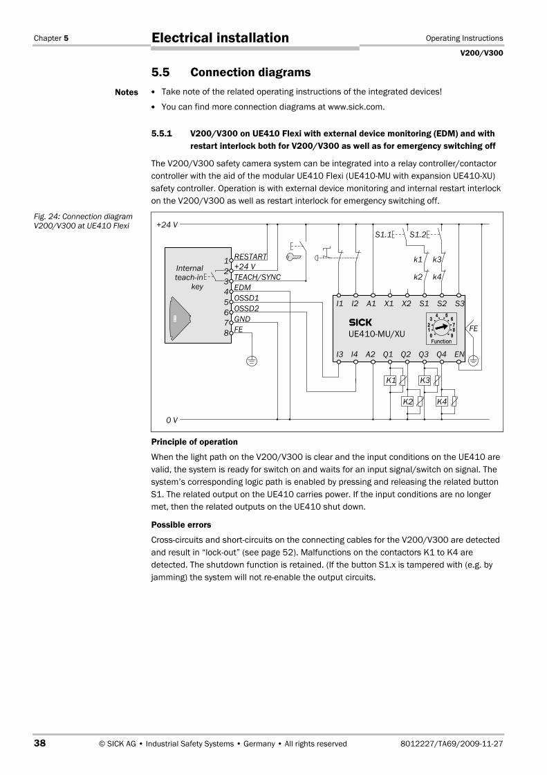
5.5.1 V200/V300 on UE410 Flexi with external device monitoring (EDM) and with
restart interlock both for V200/V300 as well as for emergency switching off
The V200/V300 safety camera system can be integrated into a relay controller/contactor
controller with the aid of the modular UE410 Flexi (UE410MU with expansion UE410XU)
safety controller. Operation is with external device monitoring and internal restart interlock
on the V200/V300 as well as restart interlock for emergency switching off.
Principle of operation
When the light path on the V200/V300 is clear and the input conditions on the UE410 are
valid, the system is ready for switch on and waits for an input signal/switch on signal. The
system’s corresponding logic path is enabled by pressing and releasing the related button
S1. The related output on the UE410 carries power. If the input conditions are no longer
met, then the related outputs on the UE410 shut down.
Possible errors
Cross-circuits and short-circuits on the connecting cables for the V200/V300 are detected
and result in “lockout” (see page 52). Malfunctions on the contactors K1 to K4 are
detected. The shutdown function is retained. (If the button S1.x is tampered with (e.g. by
jamming) the system will not re-enable the output circuits.
Notes
Fig. 24: Connection diagram
V200/V300 at UE410 Flexi
FE
+24 V
0 V
1
2
3
4
5
6
7
8
Internal
teach-in
key
RESTART
+24 V
TEACH/SYNC
EDM
OSSD1
OSSD2
GND
FE
K3K1
k1
k2
S1.1
I1 I2 A1 X1 X2 S1 S2 S3
I3 I4 A2 Q1 Q2 Q3 Q4 EN
K4K2
�
UE410-MU/XU
k3
k4
S1.2
Operating Instructions Chapter 5
V200/V300
8012227/TA69/2009-11-27 © SICK AG • Industrial Safety Systems • Germany • All rights reserved 39
Electrical installation
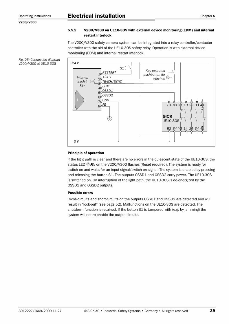
5.5.2 V200/V300 on UE103OS with external device monitoring (EDM) and internal
restart interlock
The V200/V300 safety camera system can be integrated into a relay controller/contactor
controller with the aid of the UE103OS safety relay. Operation is with external device
monitoring (EDM) and internal restart interlock.
Principle of operation
If the light path is clear and there are no errors in the quiescent state of the UE103OS, the
status LED ���� on the V200/V300 flashes (Reset required). The system is ready for
switch on and waits for an input signal/switch on signal. The system is enabled by pressing
and releasing the button S1. The outputs OSSD1 and OSSD2 carry power. The UE103OS
is switched on. On interruption of the light path, the UE103OS is de-energized by the
OSSD1 and OSSD2 outputs.
Possible errors
Cross-circuits and short-circuits on the outputs OSSD1 and OSSD2 are detected and will
result in “lockout” (see page 52). Malfunctions on the UE103OS are detected. The
shutdown function is retained. If the button S1 is tampered with (e.g. by jamming) the
system will not re-enable the output circuits.
Fig. 25: Connection diagram
V200/V300 at UE103OS +24 V
0 V
1
2
3
4
5
6
7
8
Internal
teach-in
key
RESTART
+24 V
TEACH/SYNC
EDM
OSSD1
OSSD2
GND
FE
S1
B1 B3 Y1 13 23 33 41
B2 B4 Y2 14 24 34 42
�
UE10-3OS
Key-operated
pushbutton for
teach-in
Chapter 6 Operating Instructions
V200/V300
40 © SICK AG • Industrial Safety Systems • Germany • All rights reserved 8012227/TA69/2009-11-27
Application examples
6 Application examples
The examples shown are only provided as an aid for your planning. You may need to
consider additional protection measures for your application.
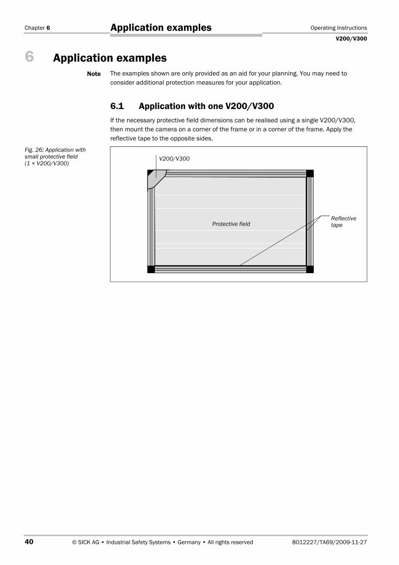
6.1 Application with one V200/V300
If the necessary protective field dimensions can be realised using a single V200/V300,
then mount the camera on a corner of the frame or in a corner of the frame. Apply the
reflective tape to the opposite sides.
Note
Fig. 26: Application with
small protective field
(1 × V200/V300)
Protective field
V200/V300
Reflectivetape

Operating Instructions Chapter 6
V200/V300
8012227/TA69/2009-11-27 © SICK AG • Industrial Safety Systems • Germany • All rights reserved 41
Application examples
6.2 Application with two V200/V300
If the application requires a larger protective field width that can be covered with one
V200/V300, or the hazardous point is to be protected in an ergonomic manner, you can
mount two V200/V300 in parallel in opposite directions (see Fig. 27) or at the corners (see
Fig. 28). In this way you can realise two overlapping protective fields.
� Mount the devices overlapping as shown in the figure (i.e. not back to back). Otherwise
un-monitored areas may be produced.
� Ensure the housing markings on the two cameras are aligned.
� You must synchronise the two V200/V300 with each other so that they do not interfere
with each other (see section 5.4 on page 37).
Notes
Fig. 27: Application with
large protective field
(2 × V200/V300)
Protective field 1
�Unmonitored
areas!
All-roundreflective tapeProtective field 2
Area where both protective fields overlap
Chapter 6 Operating Instructions
V200/V300
42 © SICK AG • Industrial Safety Systems • Germany • All rights reserved 8012227/TA69/2009-11-27
Application examples
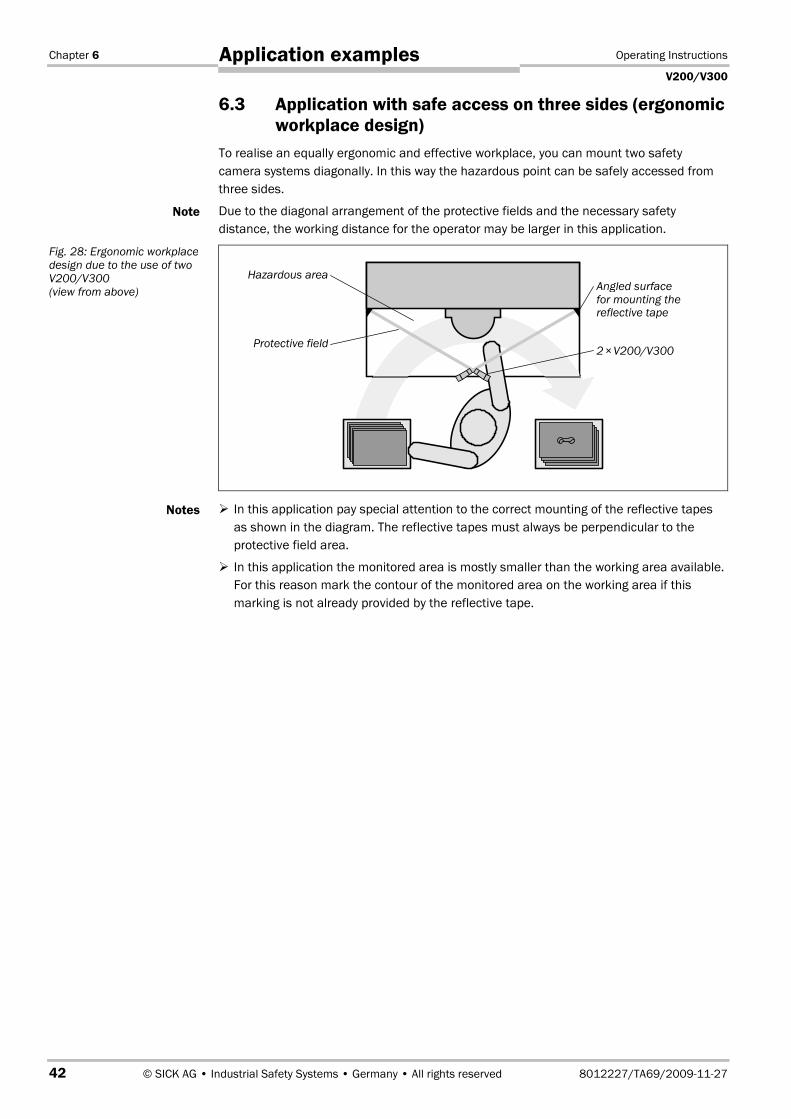
6.3 Application with safe access on three sides (ergonomic
workplace design)
To realise an equally ergonomic and effective workplace, you can mount two safety
camera systems diagonally. In this way the hazardous point can be safely accessed from
three sides.
Due to the diagonal arrangement of the protective fields and the necessary safety
distance, the working distance for the operator may be larger in this application.
� In this application pay special attention to the correct mounting of the reflective tapes
as shown in the diagram. The reflective tapes must always be perpendicular to the
protective field area.
� In this application the monitored area is mostly smaller than the working area available.
For this reason mark the contour of the monitored area on the working area if this
marking is not already provided by the reflective tape.
Note
Fig. 28: Ergonomic workplace
design due to the use of two
V200/V300
(view from above)
Notes
2×V200/V300
Hazardous area
Protective field
Angled surface
for mounting thereflective tape
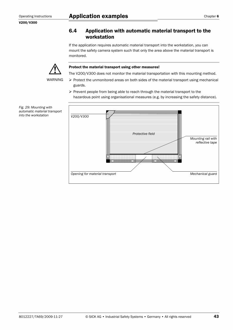
Operating Instructions Chapter 6
V200/V300
8012227/TA69/2009-11-27 © SICK AG • Industrial Safety Systems • Germany • All rights reserved 43
Application examples
6.4 Application with automatic material transport to the
workstation
If the application requires automatic material transport into the workstation, you can
mount the safety camera system such that only the area above the material transport is
monitored.
Protect the material transport using other measures!
The V200/V300 does not monitor the material transportation with this mounting method.
� Protect the unmonitored areas on both sides of the material transport using mechanical
guards.
� Prevent people from being able to reach through the material transport to the
hazardous point using organisational measures (e.g. by increasing the safety distance).
�WARNING
Fig. 29: Mounting with
automatic material transport
into the workstation V200/V300
Mounting rail with
reflective tape
Protective field
Opening for material transport Mechanical guard

Chapter 7 Operating Instructions
V200/V300
44 © SICK AG • Industrial Safety Systems • Germany • All rights reserved 8012227/TA69/2009-11-27
Commissioning
7 Commissioning
Commissioning requires a thorough check by qualified safety personnel!
Before you operate a system protected by the V200/V300 safety camera system for the
first time, make sure that the system is first checked and released by qualified safety
personnel. Please read the notes in chapter 2 “On safety” on page 9.
7.1 Test notes
The purpose of the tests described in the following is to confirm the safety requirements
specified in the national/international rules and regulations, especially the safety
requirements in the Machine and Work Equipment Directive (EU Conformity).
These tests are also used to identify if the protection is affected by external light sources
or other unusual ambient effects.
These tests must therefore always be performed.
7.2 Pre-commissioning tests
� Check the effectiveness of the protective device mounted to the machine, using all
selectable operating modes as specified in the checklist in the annex (see 13.2
“Checklist for the manufacturer” on page 64).
� Ensure that the operating personnel of the machine protected by the safety camera
system are correctly instructed by qualified safety personnel before being allowed to
operate the machine. Instructing the operating personnel is the responsibility of the
machine owner.
7.3 Regular inspection of the protective device by qualified
safety personnel
� Check the system, following the inspection intervals specified in the national rules and
regulations. This procedure ensures that any changes on the machine or manipulations
of the protective device after the initial commissioning are detected.
� If any modifications have been made to the machine or the protective device, or if the
safety camera system has been changed or repaired, the system must be checked
again as specified in the checklist in the annex.
�WARNING

Operating Instructions Chapter 7
V200/V300
8012227/TA69/2009-11-27 © SICK AG • Industrial Safety Systems • Germany • All rights reserved 45
Commissioning
7.4 Tests of the protective device by a specialist or
authorised personnel
Do not operate the machine if the green or yellow LED is lit during the test. During the
check only the Red LED is allowed to illuminate!
If the � or the � LED lights up during the test even for a short period, work must stop at
the machine. In this case the installation of the safety camera system must be checked by
qualified safety personnel.
When must the protective device be checked?
� The protective device must be checked daily by a specialist or by authorised personnel.
� The protective device must be checked each time the operator changes.
How to check the protective device:
� Check the protective device for correct seating and for damage, in particular the
mounting, the electrical connection, the front screen and the reflective tape.
� Check that personnel or body parts can only intrude into the hazardous area through
the protective field of the V200/V300 (e.g. if a mechanical guard has been removed).
� Check whether the protective device is effective for the set operating mode.
� Choose the test rod that matches the resolution used. The diameter of the test rod must
correspond to the actual resolution of the system achieved by the resolution set that
has been used.
� Guide the test rod slowly along the outer edge of the protective field as shown in
Fig. 30.
�WARNING
Fig. 30: Daily test of the
protective device with
the test rod

Chapter 8 Operating Instructions
V200/V300
46 © SICK AG • Industrial Safety Systems • Germany • All rights reserved 8012227/TA69/2009-11-27
Configuration
8 Configuration
Ensure the machine is in a safe condition!
While you configure the safety camera system, the machine could start unintentionally.
� Ensure that the whole system is in a safe condition during the configuration process.
8.1 Teach-in
Prior to initial commissioning, you must perform a new teach-in procedure. The following
occurs during teach-in:
� The V200/V300 detects the current connection configuration and configures the
internal restart interlock, the external device monitoring and the locking of the internal
teach-in key to suit. In the default delivery status, these functions are deactivated.
� The V200/V300 detects the protective field based on the reflective tape. In the default
delivery status, the V200/V300 has no protective field configured.
How to teach-in the current configuration and shape of the protective field:
� Ensure camera and reflective tape are correctly mounted and the electrical connections
have been made.
� Switch on the V200/V300. The � LED is constantly illuminated.
Ensure there are no objects in the protective field during teach-in!
Only the longest contiguous section of the reflective tape is taught-in by the
V200/V300. If there are gaps in the reflection, e.g. because the reflective tape has
been damaged or because there is an object in the protective field, the safety camera
system will ignore the shorter section of the reflective tape.
� Start the teach-in process as follows:
Using the internal teach-in key Using the key-operated pushbutton
for teach-in
Actuate the internal teach-in key using the
teach-in pin as follows:
� Actuate for approx. 5 s
(the diagnostics LED 4 ��� flashes 5 times).
If the V200/V300 does not react, the
internal teach-in key is probably locked.
Start the teach-in process using the key-
operated pushbutton for teach-in or unlock
the teach-in key (see section 8.4 “Locking
the internal teach-in key” on page 50).
� Release for approx. 2 seconds
(the diagnostics LED 4 ��� flashes 2 times).
� Actuate for approx. 5 s
(the diagnostics LED 4 ��� flashes 5 times).
� Important: Now remove your hand from the
protective field so that the V200/V300 can
completely detect the protective field.
� Press the external key-operated
pushbutton for teach-in for at
least 0.5 seconds.
The diagnostics LED 4 �
illuminates.
� Release the key-operated
pushbutton for teach-in.
The diagnostics LED 4 � goes off.
�WARNING
�WARNING
Tab. 11: Starting the
teachin process

Operating Instructions Chapter 8
V200/V300
8012227/TA69/2009-11-27 © SICK AG • Industrial Safety Systems • Germany • All rights reserved 47
Configuration
The V200/V300 now teaches-in the current configuration and shape of the protective
field. The process takes approx. 15 seconds. During the teach-in the flashing
diagnostics LEDs indicate the configuration detected:
Display Meaning
1 ��� OSSDs detected and OK
2 ��� External device monitoring (EDM) detected and activated
3 ��� Reset button detected and restart interlock activated
4 ��� Internal teach-in key unlocked
� Using the LEDs, check whether the teach-in was successful:
Status LEDs Diagnostics LEDs
� � 1 2 3 4
Meaning
� � � � � � � Teach-in was successful. If the protective
field is clear and the restart interlock is
deactivated, the V200/V300 switches to
green.
� ��� � � � � � Teach-in was successful. If the protective
field is clear and restart interlock is
activated, the V200/V300 waits until the
reset button is operated.
� � � � � � � Teach-in has failed (for measures see
below).
� After teach-in it is imperative you check the protective field (see section 7.4 “Tests of
the protective device by a specialist or authorised personnel” on page 45).
If the teach-in fails:
� Check and rectify as necessary the following causes:
– Is the reflector fitted and clean?
– Is the reflector perpendicular to the area of the protective field?
– Is the reflective tape or are sub-segments of the tape very short?
– Are there other reflective objects in the immediate vicinity that could interfere with
the system (e.g. reflective strips on safety clothing, packaging film, etc.)?
� Remove the cause.
� Perform teach-in again.
Tab. 12: Meaning of the
diagnostics LEDs during
teach-in
Tab. 13: LED displays
after teach-in

Chapter 8 Operating Instructions
V200/V300
48 © SICK AG • Industrial Safety Systems • Germany • All rights reserved 8012227/TA69/2009-11-27
Configuration
8.2 Internal restart interlock
The configuration of the restart interlock is defined by the wiring that is in place during the
first or last teach-in process performed.
How to activate the internal restart interlock:
� Make the electrical connections for the reset button (see section 5.3 on page 35).
� Switch on the V200/V300.
� Perform a teach-in procedure.
If there is no signal on the Reset/restart input, then the safety camera system will
activate the internal restart interlock and save this configuration in the device. The
device is now waiting for the reset button to be pressed.
� Check the effectiveness of the protective device as described in section 7.1 “Test
notes” on page 44.
How to deactivate the internal restart interlock:
� Permanently connect the Reset/restart input to 24 V (see section 5.2 on page 35).
� Switch on the V200/V300.
� Perform a teach-in procedure.
If 24 V are present on the Reset/restart input, the safety camera system will deactivate
the internal restart interlock and save this configuration in the device.
� Check the effectiveness of the protective device as described in section 7.1 “Test
notes” on page 44.
Operating Instructions Chapter 8
V200/V300
8012227/TA69/2009-11-27 © SICK AG • Industrial Safety Systems • Germany • All rights reserved 49
Configuration
8.3 External device monitoring
In the default delivery status, the external device monitoring is deactivated.
How to activate the external device monitoring:
� Make the electrical connections (see section 5.3 on page 35).
� Switch on the V200/V300.
� Perform a teach-in procedure.
If the contacts to be monitored are connected to the external device monitoring (EDM)
input, then the safety camera system will activate the external device monitoring and
save this configuration in the device.
The external device monitoring will remain deactivated without teach-in!
If you place the system in operation after connecting the contacts to the external device
monitoring (EDM) input without teach-in, then the external device monitoring will remain
deactivated. The system can therefore switch to green despite faulty contactors.
� Check the effectiveness of the protective device as described in section 7.1 “Test
notes” on page 44.
How to deactivate the external device monitoring:
� Permanently connect the External device monitoring (EDM) input to 0 V (see section 5.2
on page 35).
� Switch on the V200/V300.
� Perform a teach-in procedure.
If there is no signal or 0 V on the external device monitoring (EDM) input, the safety
camera system will deactivate the external device monitoring and save this
configuration in the device.
� Check the effectiveness of the protective device as described in section 7.1 “Test
notes” on page 44.
�WARNING
Chapter 8 Operating Instructions
V200/V300
50 © SICK AG • Industrial Safety Systems • Germany • All rights reserved 8012227/TA69/2009-11-27
Configuration
8.4 Locking the internal teach-in key
In the default delivery status the internal teach-in key is unlocked, i.e. it can be used. To
permit remote teach-in and/or to protect the configuration, you can connect an external
key-operated pushbutton for teach-in and lock the internal teach-in key.
How to lock the internal teach-in key:
� Connect an external key-operated pushbutton for teach-In (see section 5.3 on page 35).
� Switch on the V200/V300.
� Perform a teach-in procedure using the key-operated pushbutton for teach-in.
The V200/V300 locks the internal teach-in key and saves this configuration in the
device. Teach-in can now only be performed using the key-operated pushbutton for
teach-in.
� Check the effectiveness of the protective device as described in section 7.1 “Test
notes” on page 44.
How to unlock the internal teach-in key:
� Switch on the V200/V300.
� Press the key-operated pushbutton for teach-in for at least 60 seconds.
The V200/V300 unlocks the internal teach-in key and saves this configuration in the
device.
� If you no longer need the key-operated pushbutton for teach-in, remove it from the
electrical installation. Otherwise the V200/V300 will again lock the internal teach-in key
the next time the key-operated pushbutton for teach-in is actuated.
� Check the effectiveness of the protective device as described in section 7.1 “Test
notes” on page 44.
Operating Instructions Chapter 9
V200/V300
8012227/TA69/2009-11-27 © SICK AG • Industrial Safety Systems • Germany • All rights reserved 51
Care and maintenance
9 Care and maintenance
The V200/V300 safety camera system is maintenance-free in operation. The front screen
on the V200/V300 as well as the reflective tape should be cleaned regularly and also
cleaned immediately in case of soiling.
� Do not use aggressive cleaning agents.
� Do not use abrasive cleaning agents.
Static charges cause dust particles to be attracted to the front screen and the reflective
tape. You can reduce this effect by using the antistatic plastic cleaner (SICK part number
5600006) and the SICK lens cloth (part number 4003353).
How to clean the front screen and the reflective tape:
� Use a clean and soft brush to remove dust from the front screen and the reflective tape.
� Then wipe the front screen and the reflective tape with a clean and damp cloth.
� After cleaning, check the position of the camera and check the reflective tape for good
condition to ensure it is not possible to reach over, reach under or stand behind the
protective device.
� Check the effectiveness of the protective device as described in section 7.1 “Test
notes” on page 44.
Note
Note
Chapter 10 Operating Instructions
V200/V300
52 © SICK AG • Industrial Safety Systems • Germany • All rights reserved 8012227/TA69/2009-11-27
Fault diagnosis
10 Fault diagnosis
This chapter describes how to identify and rectify errors and malfunctions during the
operation of the safety camera system.
10.1 In the event of faults or errors
Cease operation if the cause of the malfunction has not been clearly identified!
� Stop the machine if you cannot clearly identify or allocate the error and if you cannot
safely rectify the malfunction.
The system state “lockout”
In case of certain faults or an erroneous configuration, the system can go into the
“lockout” state. The status LED � flashes with a short duty cycle �� (short on/long off).
To place the device back in operation:
� Rectify the cause of the fault following the information given in this chapter.
� Switch the power supply for the V200/V300 off and on again (e.g. by unplugging the
system plug and reinserting it).
10.2 SICK support
� If you cannot rectify an error with the help of the information provided in this chapter,
please contact your local SICK representative.
�WARNING

Operating Instructions Chapter 10
V200/V300
8012227/TA69/2009-11-27 © SICK AG • Industrial Safety Systems • Germany • All rights reserved 53
Fault diagnosis
10.3 Warnings and error messages of the LEDs
This section explains the meaning of the indications on the LEDs in case of warnings and
errors and how you can react to them.
The procedure for troubleshooting varies for warnings ��� and errors �� only in the last
step: If there is an error, you must re-start the V200/V300 after rectification.
Status LEDs Diagnostics LEDs
� � 1 2 3 4
Meaning Rectification of the error
� ��� � ��� � � � Warning
� �� � �� � � � Error
Short-circuit or
overcurrent on
an OSSD
� Check the contactor. Replace, if
necessary.
� Check the wiring for short-circuits or
cross-circuits.
� ��� � � ��� � � Warning
� �� � � �� � � Error
External device
monitoring
� Check the contactors and their wiring,
eliminate any wiring errors, if necessary.
� Switch the device off and back on again.
Check the configuration of the external
device monitoring (see page 16).
� ��� � � � ��� � Warning
� �� � � � �� � Error
Reset button � Check the reset button for correct
function. The button may be defective
or stuck.
� Check the wiring of the reset button for
any short-circuit to 24 V.
� ��� � � � � ��� Warning
� �� � � � � �� Error
TEACH input � Check the connection of the external
key-operated pushbutton for teach-in.
� �� � �� �� �� �� Error System error � Disconnect the supply voltage to the
V200/V300 for at least 3 seconds.
� If the problem persists, replace the unit.
Tab. 14: Indications on completion of the teach-in

Chapter 11 Operating Instructions
V200/V300
54 © SICK AG • Industrial Safety Systems • Germany • All rights reserved 8012227/TA69/2009-11-27
Technical specifications
11 Technical specifications
11.1 Data sheet
Minimum Typical Maximum
General system data
Protective field dimensions See section 4.1 “Checking the dimensions of the
protective field” on page 19ff.
Type
V200 Work Station Extended 2 (EN 61�4961, IEC/TR 61�4964)
V300 Work Station Extended 3 (EN 61�4961, IEC/TR 61�4964)
Safety integrity level2)
V200 Work Station Extended SIL1 (IEC 61�508)
V300 Work Station Extended SIL2 (IEC 61�508)
SIL claim limit2)
V200 Work Station Extended SILCL1 (EN 62�061)
V300 Work Station Extended SILCL2 (EN 62�061)
Category
V200 Work Station Extended 2 (EN ISO 13�8491)
V300 Work Station Extended 3 (EN ISO 13�8491)
Performance Level2)
V200 Work Station Extended PL c (EN ISO 13�8491)
V300 Work Station Extended PL d (EN ISO 13�8491)
Test rate 50 ¹/s (EN ISO 13�8491)
Demand rate3)
30 ¹/min (EN ISO 13�8491)
PFHd (mean probability of a
dangerous failure per hour)
3.2 × 10⁻⁹
TM (mission time) 20 years (EN ISO 13�849)
Protection class III (EN 50�178)
Enclosure rating IP 54 (EN 60�529)
Resolution 20 mm, 24 mm or 30 mm
Field of view 103° ± 3°
Ambient operating temperature 0 °C +50 °C
Storage temperature –25 °C +70 °C (≤24 h)
Humidity, taking into account the
operating temperature range
EN 61�4961, section 5.1.2 and section 5.4.2 as
well as IEC/TR 61�4964, section 5.4.2
Air humidity (non-dewing) 15�% 95�%
Sinusoidal vibration 5 g, 10–55 Hz (EN 60�06826)
Shock resistance 10 g, 16 ms (EN 60�068227)
Lighting
Wavelength 850 nm
Occular safety Photobiologically harmless (IEC 62�4717)
2)For detailed information on the exact design of your machine/system, please contact your local SICK
representative.3)
For V200 Work Station Extended the following applies: Between two demands for a safety-related reaction
from the device, at least 100 internal or external tests must be performed.
Tab. 15: Data sheet
V200/V300
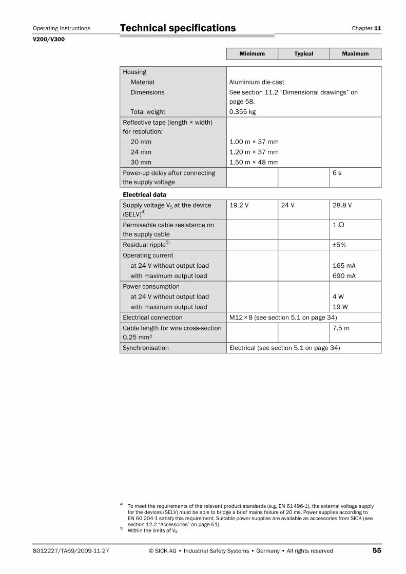
Operating Instructions Chapter 11
V200/V300
8012227/TA69/2009-11-27 © SICK AG • Industrial Safety Systems • Germany • All rights reserved 55
Technical specifications
Minimum Typical Maximum
Housing
Material Aluminium die-cast
Dimensions See section 11.2 “Dimensional drawings” on
page 58.
Total weight 0.355 kg
Reflective tape (length × width)
for resolution:
20 mm 1.00 m × 37 mm
24 mm 1.20 m × 37 mm
30 mm 1.50 m × 48 mm
Power-up delay after connecting
the supply voltage
6 s
Electrical data
Supply voltage VS at the device
(SELV)4)
19.2 V 24 V 28.8 V
Permissible cable resistance on
the supply cable
1 �
Residual ripple5)
±5%
Operating current
at 24 V without output load 165 mA
with maximum output load 690 mA
Power consumption
at 24 V without output load 4 W
with maximum output load 19 W
Electrical connection M12�×8 (see section 5.1 on page 34)
Cable length for wire cross-section
0.25 mm²
7.5 m
Synchronisation Electrical (see section 5.1 on page 34)
4)To meet the requirements of the relevant product standards (e.g. EN 61�4961), the external voltage supply
for the devices (SELV) must be able to bridge a brief mains failure of 20 ms. Power supplies according to
EN 60�2041 satisfy this requirement. Suitable power supplies are available as accessories from SICK (see
section 12.2 “Accessories” on page 61).5)
Within the limits of VS.
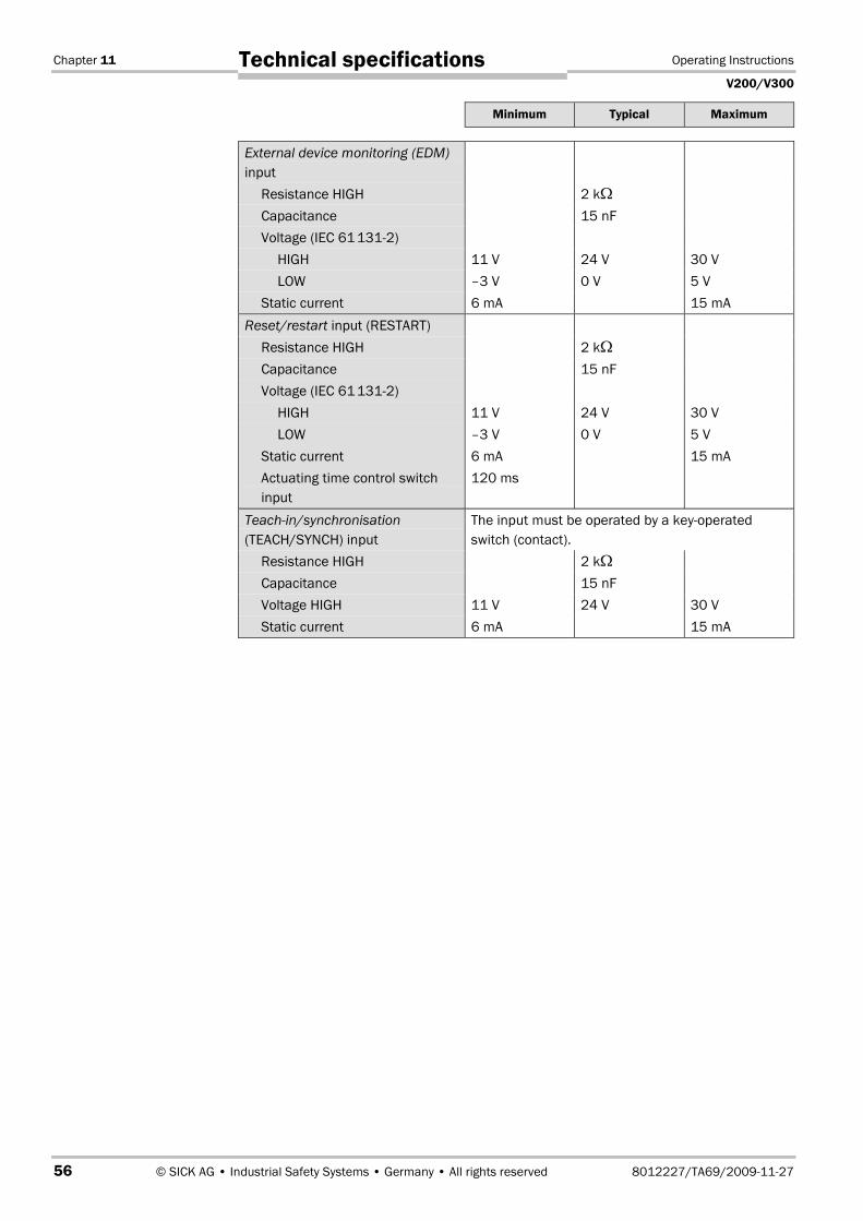
Chapter 11 Operating Instructions
V200/V300
56 © SICK AG • Industrial Safety Systems • Germany • All rights reserved 8012227/TA69/2009-11-27
Technical specifications
Minimum Typical Maximum
External device monitoring (EDM)
input
Resistance HIGH 2 k�
Capacitance 15 nF
Voltage (IEC 61�1312)
HIGH 11 V 24 V 30 V
LOW –3 V 0 V 5 V
Static current 6 mA 15 mA
Reset/restart input (RESTART)
Resistance HIGH 2 k�
Capacitance 15 nF
Voltage (IEC 61�1312)
HIGH 11 V 24 V 30 V
LOW –3 V 0 V 5 V
Static current 6 mA 15 mA
Actuating time control switch
input
120 ms
Teach-in/synchronisation
(TEACH/SYNCH) input
The input must be operated by a key-operated
switch (contact).
Resistance HIGH 2 k�
Capacitance 15 nF
Voltage HIGH 11 V 24 V 30 V
Static current 6 mA 15 mA

Operating Instructions Chapter 11
V200/V300
8012227/TA69/2009-11-27 © SICK AG • Industrial Safety Systems • Germany • All rights reserved 57
Technical specifications
Minimum Typical Maximum
Output signal switching devices
(OSSDs)
2 PNP semiconductors, short-circuit protected6)
,
cross-circuit monitored
Switching voltage HIGH
(active, Urms) at 250 mA
VS – 2.7 V VS
Switching voltage LOW
(inactive)
0 V 0 V 3.5 V
Source switching current 6 mA 250 mA7)
Leakage current8)
250 µA
Load inductance 2.2 H
Load capacity at 50 � 2.2 µF
Permissible line resistance
between device and load9)
2.5 �
Test pulse data10)
Test pulse width 230 µs 300 µs
Test frequency 120 ms
Response time 20 ms
Switch off time 100 ms
Power-up delay of the OSSDs
from red to green
30 ms
Contactors
Permissible dropout time 300 ms
Permissible pick-up time 300 ms
6)Applies to the voltage range between UV and 0 V.
7)Switching currents ≤500 mA are allowed briefly (≤100 ms).
8)In the case of a fault (0 V cable open circuit) the maximum leakage current flowing in the OSSD cable. The
downstream controller must detect this status as LOW. A safe PLC (Programmable Logic Controller) must be
able to identify this status.9)
Make sure to limit the individual cable resistance to the downstream controller to this value to ensure that a
cross-circuit between the outputs is safely detected. (Also note EN 60�204 Electrical Machine Equipment,
Part 1: General Requirements.)10)
When active, the outputs are tested cyclically (brief LOW). When selecting the downstream controllers, make
sure that the test pulses do not result in deactivation when using the above parameters.
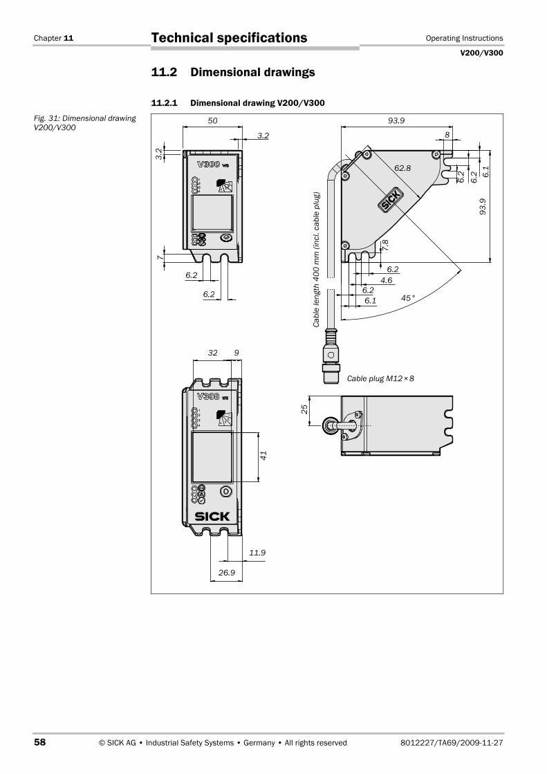
Chapter 11 Operating Instructions
V200/V300
58 © SICK AG • Industrial Safety Systems • Germany • All rights reserved 8012227/TA69/2009-11-27
Technical specifications
11.2 Dimensional drawings
11.2.1 Dimensional drawing V200/V300
Fig. 31: Dimensional drawing
V200/V300
7
50
32
25
6.2
11.9
93.9
8
62.8
93
.9
6.2
Cable plug M12�×8
45°
41
6.1
6.2
7.8
6.2
26.9
9
6.2
Ca
ble
len
gth
40
0m
m(i
ncl.
ca
ble
plu
g)
6.1
4.6
3.2
3.2
6.2
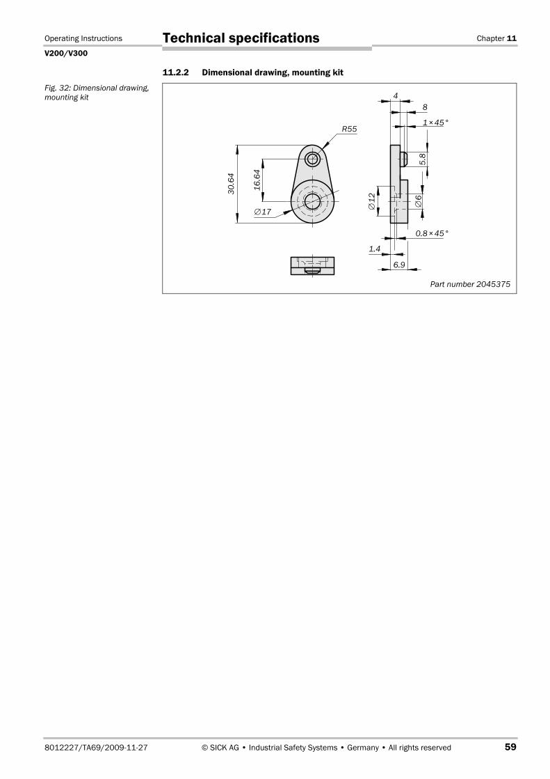
Operating Instructions Chapter 11
V200/V300
8012227/TA69/2009-11-27 © SICK AG • Industrial Safety Systems • Germany • All rights reserved 59
Technical specifications
11.2.2 Dimensional drawing, mounting kit
Fig. 32: Dimensional drawing,
mounting kit
Part number 2045375
16
.64
R55
4
8
1×45°
5.8
30
.64
6.9
1.4
∅17
∅6
∅1
2
0.8×45°
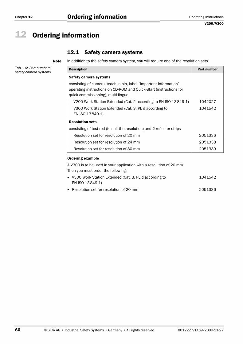
Chapter 12 Operating Instructions
V200/V300
60 © SICK AG • Industrial Safety Systems • Germany • All rights reserved 8012227/TA69/2009-11-27
Ordering information
12 Ordering information
12.1 Safety camera systems
In addition to the safety camera system, you will require one of the resolution sets.
Description Part number
Safety camera systems
consisting of camera, teach-in pin, label “Important Information”,
operating instructions on CDROM and QuickStart (instructions for
quick commissioning), multi-lingual
V200 Work Station Extended (Cat. 2 according to EN ISO 13�8491) 1042027
V300 Work Station Extended (Cat. 3, PL d according to
EN ISO 13�8491)
1041542
Resolution sets
consisting of test rod (to suit the resolution) and 2 reflector strips
Resolution set for resolution of 20 mm 2051336
Resolution set for resolution of 24 mm 2051338
Resolution set for resolution of 30 mm 2051339
Ordering example
A V300 is to be used in your application with a resolution of 20 mm.
Then you must order the following:
� V300 Work Station Extended (Cat. 3, PL d according to
EN ISO 13�8491)
1041542
� Resolution set for resolution of 20 mm 2051336
Note
Tab. 16: Part numbers
safety camera systems
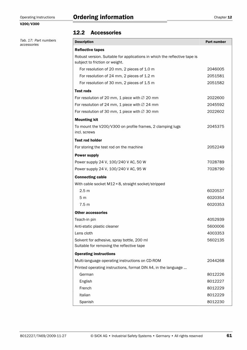
Operating Instructions Chapter 12
V200/V300
8012227/TA69/2009-11-27 © SICK AG • Industrial Safety Systems • Germany • All rights reserved 61
Ordering information
12.2 Accessories
Description Part number
Reflective tapes
Robust version. Suitable for applications in which the reflective tape is
subject to friction or weight.
For resolution of 20 mm, 2 pieces of 1.0 m 2046005
For resolution of 24 mm, 2 pieces of 1.2 m 2051581
For resolution of 30 mm, 2 pieces of 1.5 m 2051582
Test rods
For resolution of 20 mm, 1 piece with ∅ 20 mm 2022600
For resolution of 24 mm, 1 piece with ∅ 24 mm 2045592
For resolution of 30 mm, 1 piece with ∅ 30 mm 2022602
Mounting kit
To mount the V200/V300 on profile frames, 2 clamping lugs
incl. screws
2045375
Test rod holder
For storing the test rod on the machine 2052249
Power supply
Power supply 24 V, 100/240 V AC, 50 W 7028789
Power supply 24 V, 100/240 V AC, 95 W 7028790
Connecting cable
With cable socket M12�×8, straight socket/stripped
2.5 m 6020537
5 m 6020354
7.5 m 6020353
Other accessories
Teach-in pin 4052939
Anti-static plastic cleaner 5600006
Lens cloth 4003353
Solvent for adhesive, spray bottle, 200 ml
Suitable for removing the reflective tape
5602135
Operating instructions
Multi-language operating instructions on CDROM 2044268
Printed operating instructions, format DIN A4, in the language …
German 8012226
English 8012227
French 8012229
Italian 8012229
Spanish 8012230
Tab. 17: Part numbers
accessories

Chapter 13 Operating Instructions
V200/V300
62 © SICK AG • Industrial Safety Systems • Germany • All rights reserved 8012227/TA69/2009-11-27
Annex
13 Annex
13.1 EC declaration of conformity
Fig. 33: EC declaration of
conformity (page 1)
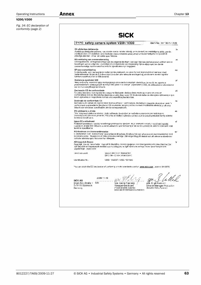
Operating Instructions Chapter 13
V200/V300
8012227/TA69/2009-11-27 © SICK AG • Industrial Safety Systems • Germany • All rights reserved 63
Annex
Fig. 34: EC declaration of
conformity (page 2)

Chapter 13 Operating Instructions
V200/V300
64 © SICK AG • Industrial Safety Systems • Germany • All rights reserved 8012227/TA69/2009-11-27
Annex
13.2 Checklist for the manufacturer
�Checklist for the manufacturer/installer for the installation of electro-sensitive protective equipment (ESPE)
Details about the points listed below must be present at least during initial commissioning — they are, however, dependent on the
respective application, the specifications of which are to be controlled by the manufacturer/installer.
This checklist should be retained and kept with the machine documentation to serve as reference during recurring tests.
1. Have the safety rules and regulations been observed in compliance with the directives/standards applicable to
the machine?
Yes � No �
2. Are the applied directives and standards listed in the declaration of conformity? Yes � No �
3. Does the protective device comply with the required PL/SILCL and PFHd as per EN ISO 13�8491/EN 62�061 and
the type as per EN 61�4961?
Yes � No �
4. Is the access to the hazardous point only possible through the protective field of the ESPE? Yes � No �
5. In the case of hazardous point protection, have appropriate measures been taken to prevent (mechanical point-
of-operation guarding) or monitor unprotected presence in the hazardous area and have these been secured
against removal?
Yes � No �
6. Are additional mechanical protective measures fitted and secured against manipulation which prevent reaching
under, over or around the ESPE?
Yes � No �
7. Has the maximum stopping and/or stopping/run-down time of the machine been measured, specified and
documented (at the machine and/or in the machine documentation)?
Yes � No �
8. Has the ESPE been mounted such that the required safety distance from the nearest hazardous point has been
achieved?
Yes � No �
9. Are the ESPE devices correctly mounted and secured against manipulation after adjustment? Yes � No �
10. Are the required protective measures against electric shock in effect (protection class)? Yes � No �
11. Is the control switch for resetting the protective device (ESPE) or restarting the machine present and correctly
installed?
Yes � No �
12. Are the outputs on the ESPE (OSSD, ASInterface Safety at Work interface) integrated in accordance with the
required PL/SILCL as per EN ISO 13�849/EN 62�061, and do they comply with the circuit diagrams?
Yes � No �
13. Has the protective function been checked in compliance with the test notes of this documentation? Yes � No �
14. Are the given protective functions effective at every setting of the operating mode selector switch? Yes � No �
15. Are the switching elements activated by the ESPE, e.g. contactors, valves, monitored? Yes � No �
16. Is the ESPE effective over the entire period of the dangerous state? Yes � No �
17. Once initiated, will a dangerous state be stopped when switching the ESPE on or off and when changing the
operating mode, or when switching to another protective device?
Yes � No �
18. Has the information label for the daily check been attached so that it is easily visible for the operator? Yes � No �
This checklist does not replace the initial commissioning, nor the regular inspection by qualified safety personnel.
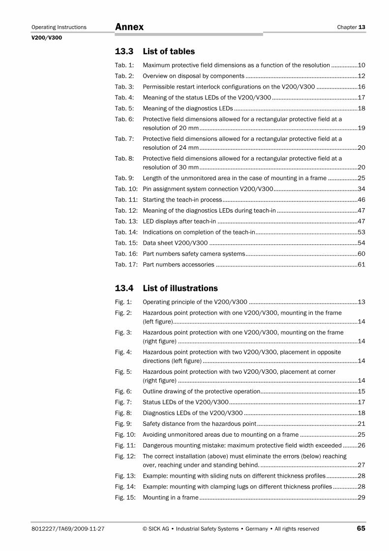
Operating Instructions Chapter 13
V200/V300
8012227/TA69/2009-11-27 © SICK AG • Industrial Safety Systems • Germany • All rights reserved 65
Annex
13.3 List of tables
Tab. 1: Maximum protective field dimensions as a function of the resolution ................10
Tab. 2: Overview on disposal by components ....................................................................12
Tab. 3: Permissible restart interlock configurations on the V200/V300 .........................16
Tab. 4: Meaning of the status LEDs of the V200/V300 ....................................................17
Tab. 5: Meaning of the diagnostics LEDs ...........................................................................18
Tab. 6: Protective field dimensions allowed for a rectangular protective field at a
resolution of 20 mm................................................................................................19
Tab. 7: Protective field dimensions allowed for a rectangular protective field at a
resolution of 24 mm................................................................................................20
Tab. 8: Protective field dimensions allowed for a rectangular protective field at a
resolution of 30 mm................................................................................................20
Tab. 9: Length of the unmonitored area in the case of mounting in a frame ..................25
Tab. 10: Pin assignment system connection V200/V300...................................................34
Tab. 11: Starting the teachin process..................................................................................46
Tab. 12: Meaning of the diagnostics LEDs during teach-in .................................................47
Tab. 13: LED displays after teach-in .....................................................................................47
Tab. 14: Indications on completion of the teach-in..............................................................53
Tab. 15: Data sheet V200/V300 ..........................................................................................54
Tab. 16: Part numbers safety camera systems....................................................................60
Tab. 17: Part numbers accessories ......................................................................................61
13.4 List of illustrations
Fig. 1: Operating principle of the V200/V300 ..................................................................13
Fig. 2: Hazardous point protection with one V200/V300, mounting in the frame
(left figure)................................................................................................................14
Fig. 3: Hazardous point protection with one V200/V300, mounting on the frame
(right figure) .............................................................................................................14
Fig. 4: Hazardous point protection with two V200/V300, placement in opposite
directions (left figure) ..............................................................................................14
Fig. 5: Hazardous point protection with two V200/V300, placement at corner
(right figure) .............................................................................................................14
Fig. 6: Outline drawing of the protective operation...........................................................15
Fig. 7: Status LEDs of the V200/V300..............................................................................17
Fig. 8: Diagnostics LEDs of the V200/V300 .....................................................................18
Fig. 9: Safety distance from the hazardous point .............................................................21
Fig. 10: Avoiding unmonitored areas due to mounting on a frame ...................................25
Fig. 11: Dangerous mounting mistake: maximum protective field width exceeded .........26
Fig. 12: The correct installation (above) must eliminate the errors (below) reaching
over, reaching under and standing behind. ...........................................................27
Fig. 13: Example: mounting with sliding nuts on different thickness profiles ...................28
Fig. 14: Example: mounting with clamping lugs on different thickness profiles ...............28
Fig. 15: Mounting in a frame ................................................................................................29
Chapter 13 Operating Instructions
V200/V300
66 © SICK AG • Industrial Safety Systems • Germany • All rights reserved 8012227/TA69/2009-11-27
Annex
Fig. 16: Correct arrangement of the reflective tapes at joints...........................................30
Fig. 17: Permissible divergence of the reflective tape from the optical axis of the
camera as a function of the distance at 20 mm resolution .................................31
Fig. 18: Permissible divergence of the reflective tape from the optical axis of the
camera as a function of the distance at 24 mm resolution .................................31
Fig. 19: Permissible divergence of the reflective tape from the optical axis of the
camera as a function of the distance at 30 mm resolution .................................32
Fig. 20: System connection V200/V300.............................................................................34
Fig. 21: Connecting the V200/V300 without external device monitoring (EDM),
without internal restart interlock and without external key-operated
pushbutton for teach-in ..........................................................................................35
Fig. 22: Connecting the V200/V300 with external device monitoring (EDM), with
internal restart interlock and with external key-operated pushbutton for
teach-in ....................................................................................................................35
Fig. 23: Connection of two V200/V300 with synchronisation ...........................................37
Fig. 24: Connection diagram V200/V300 at UE410 Flexi .................................................38
Fig. 25: Connection diagram V200/V300 at UE103OS ....................................................39
Fig. 26: Application with small protective field (1 × V200/V300) .....................................40
Fig. 27: Application with large protective field (2 × V200/V300)......................................41
Fig. 28: Ergonomic workplace design due to the use of two V200/V300 ........................42
Fig. 29: Mounting with automatic material transport into the workstation ......................43
Fig. 30: Daily test of the protective device with the test rod..............................................45
Fig. 31: Dimensional drawing V200/V300 .........................................................................58
Fig. 32: Dimensional drawing, mounting kit .......................................................................59
Fig. 33: EC declaration of conformity (page 1) ...................................................................62
Fig. 34: EC declaration of conformity (page 2) ...................................................................63

Operating Instructions Chapter 13
V200/V300
8012227/TA69/2009-11-27 © SICK AG • Industrial Safety Systems • Germany • All rights reserved 67
Annex
SICK AG | Waldkirch | Germany | www.sick.com
80
12
22
7/TA
69
/2
00
9-1
1-2
7 ∙
RV
/XX
∙ Prin
ted
in G
erm
any
(20
09
-12
) ∙ S
ubje
ct to
cha
nge
with
out n
otic
e ∙ T
he s
peci
fied
prod
uct f
eatu
res
and
tech
nica
l dat
a do
not
repr
esen
t any
gua
rant
ee ∙
A4 s
w in
t34 Australia
Phone +61 3 9497 4100 1800 33 48 02 – tollfreeE-Mail [email protected]
Belgium/LuxembourgPhone +32 (0)2 466 55 66E-Mail [email protected]
BrasilPhone +55 11 3215-4900E-Mail [email protected]
Ceská RepublikaPhone +420 2 57 91 18 50E-Mail [email protected]
ChinaPhone +852-2763 6966E-Mail [email protected]
DanmarkPhone +45 45 82 64 00E-Mail [email protected]
DeutschlandPhone +49 211 5301-301E-Mail [email protected]
EspañaPhone +34 93 480 31 00E-Mail [email protected]
FrancePhone +33 1 64 62 35 00E-Mail [email protected]
Great BritainPhone +44 (0)1727 831121E-Mail [email protected]
IndiaPhone +91–22–4033 8333E-Mail [email protected]
IsraelPhone +972-4-999-0590E-Mail [email protected]
ItaliaPhone +39 02 27 43 41E-Mail [email protected]
JapanPhone +81 (0)3 3358 1341E-Mail [email protected]
NederlandsPhone +31 (0)30 229 25 44E-Mail [email protected]
Norge Phone +47 67 81 50 00E-Mail [email protected]
ÖsterreichPhone +43 (0)22 36 62 28 8-0E-Mail [email protected]
PolskaPhone +48 22 837 40 50E-Mail [email protected]
Republic of KoreaPhone +82-2 786 6321/4E-Mail [email protected]
Republika SlovenijaPhone +386 (0)1-47 69 990E-Mail [email protected]
RomâniaPhone +40 356 171 120 E-Mail [email protected]
RussiaPhone +7 495 775 05 34E-Mail [email protected]
SchweizPhone +41 41 619 29 39E-Mail [email protected]
SingaporePhone +65 6744 3732E-Mail [email protected]
SuomiPhone +358-9-25 15 800E-Mail [email protected]
SverigePhone +46 10 110 10 00E-Mail [email protected]
TaiwanPhone +886 2 2375-6288E-Mail [email protected]
TürkiyePhone +90 216 587 74 00E-Mail [email protected]
United Arab EmiratesPhone +971 4 8865 878E-Mail [email protected]
USA/Canada/MéxicoPhone +1(952) 941-6780 1 800-325-7425 – tollfreeE-Mail [email protected]
More representatives and agencies in all major industrial nations at www.sick.com


