1 Models 1 to 4 1 – Connecting rod and piston 2 – Differential 3 – Super buggy 4x4 4 –Racing car Read and keep this booklet for future reference. V43267 UK SUBSIDIARY: Clementoni UK Ltd. Unit 10 - Brook Business Centre - Cowley Mill Road – UXBRIDGE - UB8 2FX P. +44 203 383 2020 - [email protected]MANUFACTURER: Clementoni S.p.A. Zona Industriale Fontenoce s.n.c. 62019 Recanati (MC) - Italy Tel.:+39 071 75811 - www.clementoni.com for future reference. Laboratory MECHANICS RACING CARS
Transcript
1
Models 1to 41 – Connecting rod and piston2 – Differential3 – Super buggy 4x44 –Racing car
Read and keep this booklet for future reference.
V432
67
UK SUBSIDIARY: Clementoni UK Ltd.Unit 10 - Brook Business Centre -
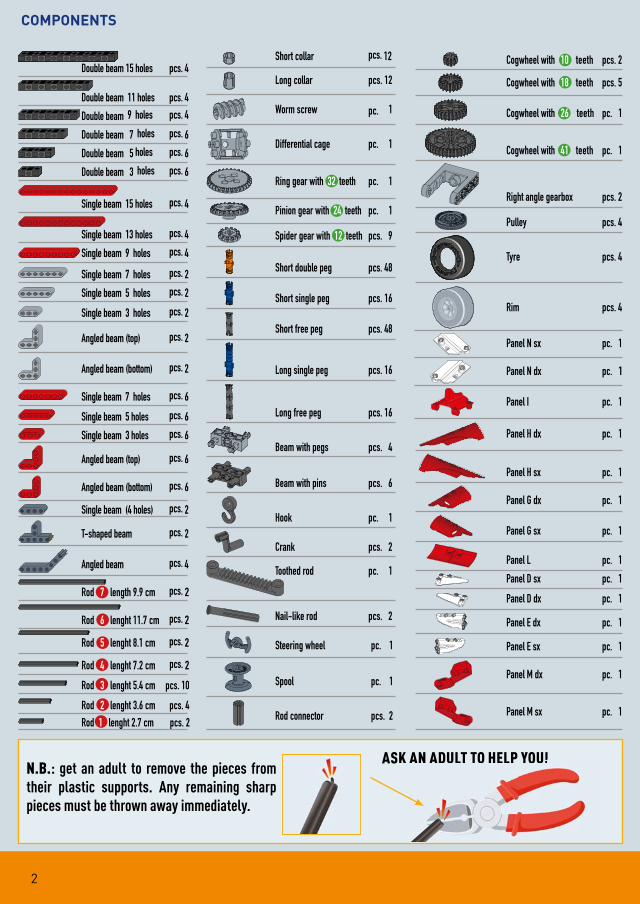
N.B.: get an adult to remove the pieces from their plastic supports. Any remaining sharp pieces must be thrown away immediately.
ASK AN ADULT TO HELP YOU!K AN ADULT TO HELP YOU!
3
The internal combustion engine
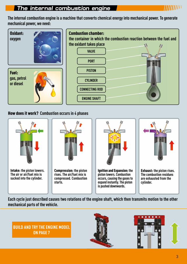
The internal combustion engine is a machine that converts chemical energy into mechanical power. To generate mechanical power, we need:
How does it work? Combustion occurs in 4 phases
Each cycle just described causes two rotations of the engine shaft, which then transmits motion to the other mechanical parts of the vehicle.
BUILD AND TRY THE ENGINE MODEL ON PAGE 7
Intake: the piston lowers. The air or air/fuel mix is sucked into the cylinder.
Compression: the piston rises. The air/fuel mix is compressed. Combustion starts.
Ignition and Expansion: the piston lowers. Combustion occurs, causing the gases to expand instantly. The piston is pushed downwards.
Exhaust: the piston rises. The combustion residues are exhausted from the cylinder.
Oxidant:
oxygen
Fuel:
gas, petrol or diesel
Combustion chamber:
the container in which the combustion reaction between the fuel and the oxidant takes place
VALVE
PORT
PISTON
CYLINDER
CONNECTING ROD
ENGINE SHAFT
4
The differential
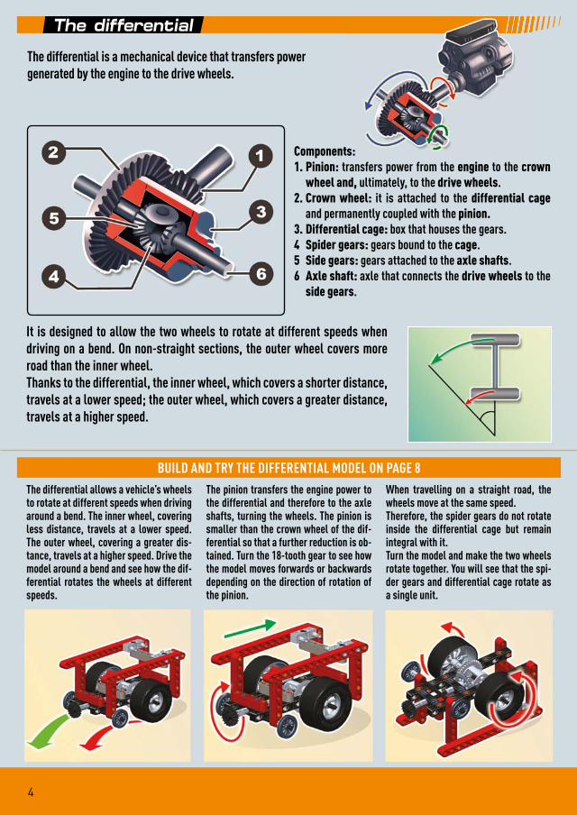
The differential is a mechanical device that transfers powergenerated by the engine to the drive wheels.
Components:
1. Pinion: transfers power from the engine to the crown
wheel and, ultimately, to the drive wheels.2. Crown wheel: it is attached to the differential cage
and permanently coupled with the pinion.
3. Differential cage: box that houses the gears.4 Spider gears: gears bound to the cage.5 Side gears: gears attached to the axle shafts.6 Axle shaft: axle that connects the drive wheels to the
side gears.
It is designed to allow the two wheels to rotate at different speeds when driving on a bend. On non-straight sections, the outer wheel covers more road than the inner wheel. Thanks to the differential, the inner wheel, which covers a shorter distance, travels at a lower speed; the outer wheel, which covers a greater distance, travels at a higher speed.
The differential allows a vehicle’s wheels to rotate at different speeds when driving around a bend. The inner wheel, covering less distance, travels at a lower speed. The outer wheel, covering a greater dis-tance, travels at a higher speed. Drive the model around a bend and see how the dif-ferential rotates the wheels at different speeds.
The pinion transfers the engine power to the differential and therefore to the axle shafts, turning the wheels. The pinion is smaller than the crown wheel of the dif-ferential so that a further reduction is ob-tained. Turn the 18-tooth gear to see how the model moves forwards or backwards depending on the direction of rotation of the pinion.
When travelling on a straight road, the wheels move at the same speed. Therefore, the spider gears do not rotate inside the differential cage but remain integral with it.Turn the model and make the two wheels rotate together. You will see that the spi-der gears and differential cage rotate as a single unit.
ts:
ransfers power from the engine to the cro
BUILD AND TRY THE DIFFERENTIAL MODEL ON PAGE 8
5
Four-wheel drive
In the case of extremely powerful engines or difficult routes due to sloping or uneven terrain, 2 drive wheels may not be enough. To overcome similar situations, certain vehicles are equipped with a four-wheel drive system, in which the engine power is transmitted to all 4 wheels and not only to the front or rear pair.
The transmission of the engine power to all 4 wheels is usually ob-tained by mounting 2 differentials, one for the front pair of wheels and the other for the rear pair. Depending on the necessities, the four-wheel drive can be configured in very different ways:
• for cars travelling on tarred roads, a third differential is necessary to optimally split the engine power;
• for cars that race on gravel roads, the differential can be left out altogether.
In the racing world, it is crucial for the vehicle’s shape to be designed according to aerodynamic criteria. Car manufacturers aim to exploit all the forces generated when a solid body (the car) moves through a fluid (the air), in order to hold the vehicle close to the ground and therefore improve its grip and manoeuvrability. To understand how these forces act, we must first analyse the concepts of lift and downforce.
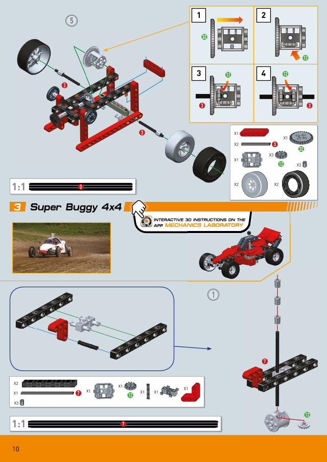
BUILD THE SUPER BUGGY 4X4 ON PAGE 10
Aerodynamics
LIFT AND DOWNFORCE
Lift is the force that counters gravity to generate an upward thrust. Let’s take the wings of an aeroplane as an example. While the aer-oplane advances, the air flows at different speeds over the two sur-faces of the wing: slower over the underside of the wing and faster over the top of the wing. The slower airflow exerts greater pressure, producing an upward thrust.If lift is the upward force, downforce is its opposite, in other words, it is a force that generates a downward thrust. In the case of a racing car, the bodywork elements, such as the spoilers, generate downforce and hold the car to the ground by exploiting the laws of aerodynamics.
6
Aerodinamica nelle auto da corsa
Aerodinamica nelle auto da corsa
Aerodynamic resistance
The wind tunnel
Countering aerodynamic resistance is another extremely im-portant aspect in the motor racing world. This is why cars are designed with extremely streamlined forms. Curved and pointed surfaces offer less resistance compared to flat and broad surfaces, therefore the nose and body of racing cars are designed according to clearly defined aerodynamic criteria. Certain vehicles, which are built to beat land speed records, look like missiles on four wheels.
Whenever we travel on foot, by bicycle or by car, the air surround-ing us opposes a force, known as aerodynamic resistance, running counter to our direction of movement. Aerodynamic re-sistance, therefore, is the force that tends to slow down a body moving through a fluid (in this case, air). If the fluid changes, this force can increase or decrease: water and air are both fluids, but it is far more difficult to walk or run in water than on the ground, because water opposes a greater resistance.
A wind tunnel is often used during the design and development phases. In this facility, a powerful fan gener-ates a flow of air that strikes the vehicle, which is bound at the centre of the tunnel. The wind tunnel allows for simulating the car’s forward movement, even though it lies still. During the tests, smoke nozzles help engineers to view the airflows moving over the bodywork, so that they can identify the aerodynamic surfaces and improve the vehicle’s design.Due to the high costs involved, scale models are often used in place of real cars inside smaller wind tunnels.
BUILD THE RACING CARON PAGE 18
7
INTERACTIVE 3D INSTRUCTIONS ON THE
APP MECHANICS LABORATORY
1
2
3
2
1
41
18
26
2
2
X2
X2 X2 X2X2X4
X2
X2
X1
X2 X2
X1
26
X1
41
1:1 1
X1 1
1:1 2
X1
X2 2 X3
X1
18
X1
1 Connecting rod and piston
8
INTERACTIVE 3D INSTRUCTIONS ON THE
APP MECHANICS LABORATORY
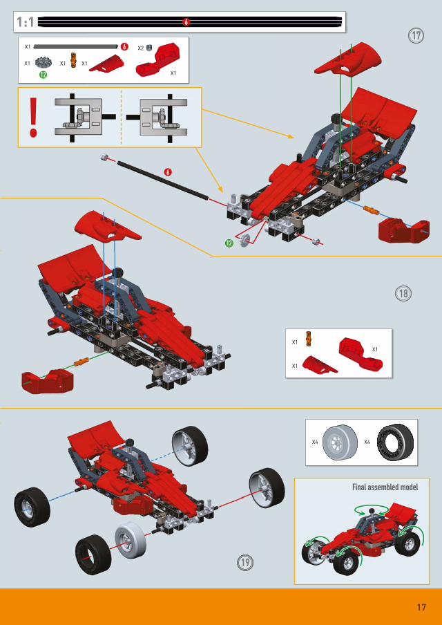
Final assembled model
4
INTERACTIVE 3D INSTRUCTIONS ON THE
APP MECHANICS LABORATORY
1
X1
X1
X2
X1X2
X4
X2
X14
X1
2 Differential
9
2
3
44
24
18
7
5
X2 X2
X1
X2
X1
X1
X4
1:1 7
X1 7
1:1 5
X1 5
X5X2
X1
18
X1
24
10
INTERACTIVE 3D INSTRUCTIONS ON THE
APP MECHANICS LABORATORY
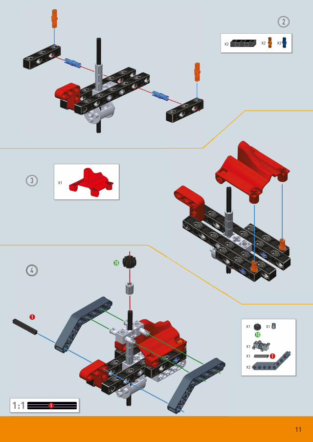
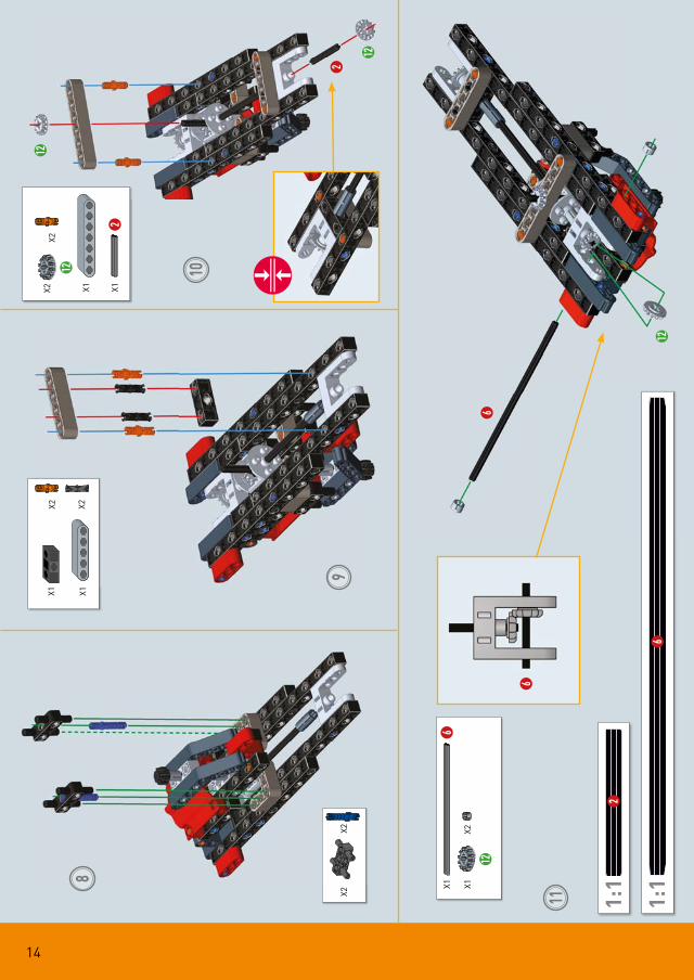
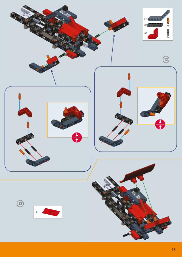
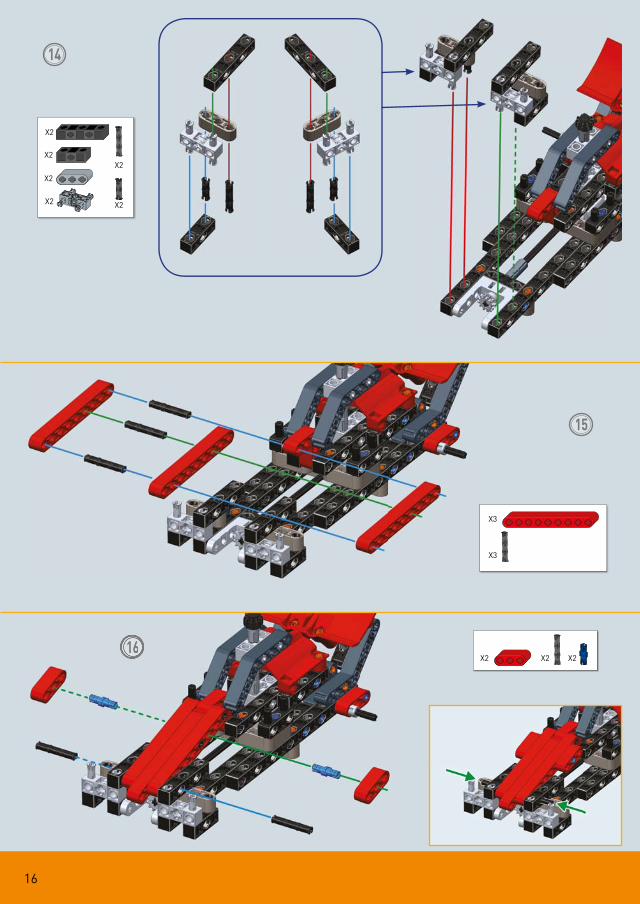
3 Super Buggy 4x4
5
1
1
3
2
412 12
12
32
3
3
3
3
X1X3
12
X1
32
1:1 3
X2 3
X2X2
X2
X1
NICS LABORATORY
7
12
1:1 7
X2
X1X1
12
X3
X1 7 X1 X1X1
11
X1
10
X1
2
3
44
1
10
X2
X1
X2 X2
1:1 1
X1 1
X2
X1
12
65
2
2
2
4
4
12
12
12
X2X2
1:1
2
1:1
4
X1X1
X1X3
12
X12
X14
13
7
X4 X2 X2X1
X2X4X4
X2X4
14
8
9
11
10
2
12
12
6
6
12
1:1
2
X12
X2X2
X1X1X1
X2
X2X2 1:1
6
6X1 X1
12
X2
X2
12
15
1313
12
X1
X2
X2
X2
X6
X4
16
14
15
1616
X2
X2
X2
X2
X2
X2
X3
X2 X2
X3
X2
17
17
!
12
6
12
18
1919
Final assembled model
1:1 6
6X1 X2
X1
12
X1 X1
X1
X1
X1
X4X4
X1
18
INTERACTIVE 3D INSTRUCTIONS ON THE
APP MECHANICS LABORATORY
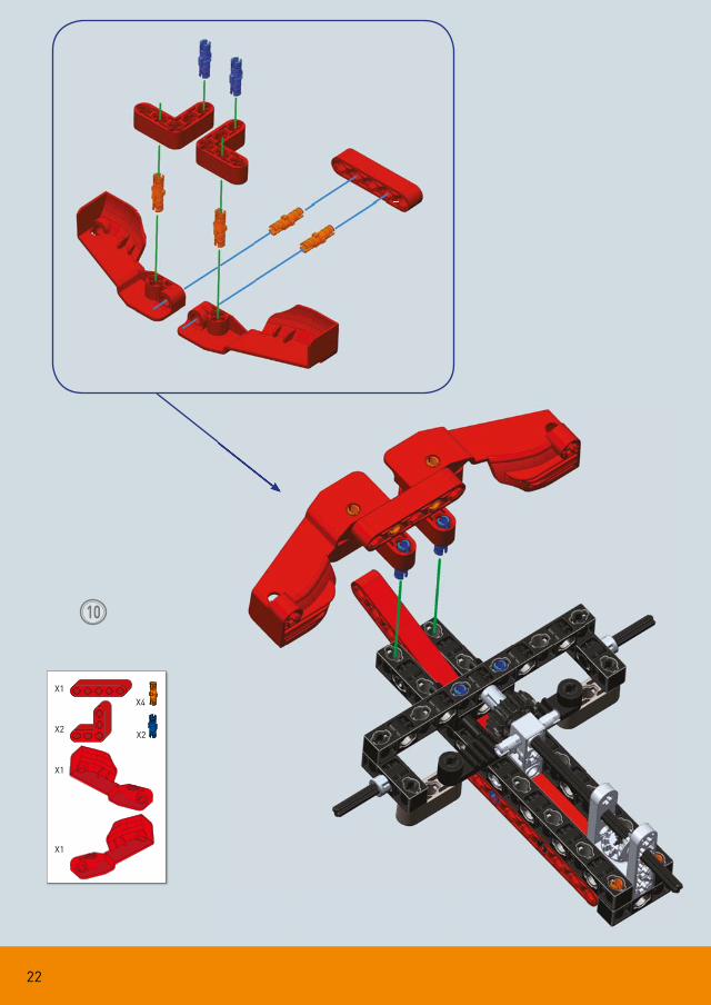
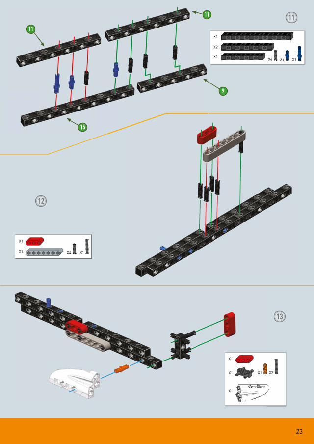
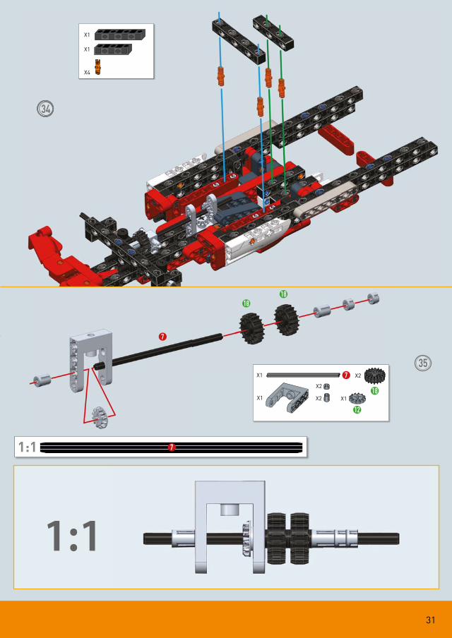
4 Racing car
1
2
APP ME
2
X2
X2
X2
X2
X2
X1
X4
19
3
4
5 6
18
X1
X2
X1
X1 X2
X1 X1
1:1 6
6X1
X1 X1 18
20
6
7
21210
A B
1:1 2
X1
X1
2
X1
10
X1
12
X1
21
8
9
6
12
12
9
X1
12
X1 X2
X2
X1
X1X2
22
10
X1
X2
X1
X1
X4
X2
23
11
12
13
11
11
15
9
X1
X1
X2
X4 X2 X1
X1
X1
X1 X4 X1
X2X1X1
X1
24
15
16
15
14
X1X1
X1 X1
X1
X1
X2
X1
X2
X2
25
17
18
19
X2
X1
X1
X1
X1X1
X1
X1
X1
26
9
15
9
1120
21
22
15
9
11
X1
X2
X1
X4 X2 X1
X1
X1 X2 X3
X1
X1
X1
27
23
24
25
24
25
X1X1
X1 X1
X2
X1
X2
X2
X1
X1
28
26
27
28
X2X1
X1
X1X2
X1
X1X1
X1
29
3
29
30
31
1
1:1 1 1:1 3
X1
X1 1
X1 3
X1 X1
X2
X1
30
32
3333
X2X2X1
X1 X1
X1
31
3434
1:1
35
7
18
12
18
X4
X1
X1
121:1 7
X1
X2
18
X1 7
X2
X2 X1
12
32
36
7
3
37
12
12
X1 3
X2
X2
12
X1
X2
1:1 3
33
6
1:1
1:1
38
3939
10
18
X1
X2 X2 X2
1:1 6
X1 6
X1 X1
X1 X1 X1
18 10
34
4040
A B
35
7
18 26
1:1
41
42
X2 X1
18
X1
26
1:1 7
X1 7
36
43
44
X1
X2
37
45
46
X2
X2
X2
X2
X1
X1
X1
38
47
A B
39
48
4949
X2
X2
X2 X2
X2
X1X2
X2
40
50
51
24
X1
X2
X1
24
X2
X1X1
X1
X1
41
12
12
32
2
32
12
12
2
1 2 3
52
53
X1
X1
X1
32
X2
12
X1
1:1 2
2
X1
42
54
5555
12
3
3
12
3 X1 X1
12
X2 3
1:1 3
X2
43
56
X2X2
X1 X2
X2
44
57
59
58
60
58
59
57
X1
X1
X1
X1
X1
X1
X1
X1
X1 X1
X1
X1
X1 X1
!
!
45
61
62
61
62
X2
X1
X1
X1
46
64
46
64
5
63
1:1 5
X2
X1 5
X2X2
X2
47
65
Final assembled model
65
2 - speed gearboxSteering mechanism activation
X4X4
48
DOWNLOAD THE FREE APP TO BUILD
20 FANTASTICMODELS
THE INTERACTIVE ANIMATIONS WILL GUIDE YOU THROUGH THE ASSEMBLY OPERATIONS IN A SIMPLE AND FUN WAY
THE INSTRUCTIONS OF ALL THE MODELS AND OF THE TECHNICAL APPLICATIONS CAN BE DOWNLOADED ALSO IN THE DIGITAL VERSION FROM THE WEBSITE
www.mechanicslaboratory.clementoni.com
The App is compatible with ANDROID™, APPLE® and AMAZON®devices:
NOT COMPATIBLEwith Windows® operating systems
45 cm
Apple and the Apple logo aretrademarks of Apple Inc., registered in the U.S. and other countries. App Store is a service mark of Apple Inc., registered in the U.S. and other countries
Google Play and the Google Play logo are trademarks of Google LLC
Amazon, and all related logosare trademarks of Amazon.com,Inc. or its affi liates.