16
Vane Motors Manual 25M, 35M, 45M, 50M Series -20 Design

Vane MotorsManual
25M, 35M, 45M, 50M Series -20 Design

There’s a certain energy at Eaton. It’s the power of integrating the competencies of some of the world’s most respected names to build a brand you can trust to meet every power management need. The energy created supports our commitment to powering business worldwide.
As the world’s demand for high-efficiency hydraulic systems for mobile and stationary applications increase, Eaton is helping to solve these challenges more reliably, efficiently, and sustainably. Our goal is simple; to provide unique solutions across a wide range of markets that keep businesses on the leading edge of change. Visit Eaton.com/hydraulics/fusion.
That’s the power of One Eaton.
The Power of One EatonHANSEN™
GROMELLE™

Eaton is a leading diversified power management company
Understanding and helping our customers succeed
• Listening and understanding to requirements and business drivers
• Delivering solutions with value propositions to solve the critical business needs
Knowing what’s important to our customers and integrating that knowledge into the fabric of our business
• …to deliver innovative, quality products
• …to respond fast
• …to provide dedicated customer service and support around the globe
Our strength is global reach with local responsiveness and support
• Customers served in more than 150 countries
• Diverse channels ensure reliable availability and support
• Design and engineering teams provide support for standard products and custom solutions
• Eaton experts offer efficient product and application training
Alternative Energy
Making energy sources technically practical and economically sound requires the kind of control made possible by high-quality components. When Eaton is on the inside, you will experience the reliable, consistent performance to create and capture energy—making renewable energy an every-day energy.
Discrete Manufacturing
Produce at peak efficiency with the superior precision and repeatability of Eaton products. Eaton hydraulic components provide the precise control and consistent operation required for virtually every step in your manufacturing operation. With Eaton, we’ll help you redefinethe meaning of raw productivity.
Oil & Gas
As the oil & gas industry continues to face further globalization and consolidation, large-scale organizations that can meet your needs in every corner of the world are more difficult to find. At Eaton, our portfolio of products is only surpassed by our tremendous reach.
Processing
Whatever your industry, no matter which processes you manage, Eaton parts and systems help keep you up and running. Our components make equipment more efficient and easier to use, so you get optimal machine performanceand maximum productivity.
Agriculture & Forestry
There’s a reason farming and forestry are called “working the land.” These segments involvesome of the hardest work and longest hours of any sector in the economy. Your productivityand profitability depend on the way you manage time and tasks.
Commercial Vehicles
Eaton technologies can make your driving operation more successful. Greater comfortand productivity help increase driver retention, while reduced emissions, leaks, and noiseimprove environmental performance. Increased efficiencies overall mean lower costs and higher net revenue.
Material Handling
Eaton hydraulic systems provide the precise control and consistent operation required for material handling and utility work. With a broad selection of products and solutions built in,Eaton helps make you a master of your domain.
Construction & Mining
When you work on a large scale, even the details are big. You need to trust every part of the equipment that lets you handle construction and mining jobs. For reliable components that deliver consistent performance in extreme conditions, turn to Eaton.
Serving eight key segments - sharing one focus
Eaton provides reliable, efficient and safe power management for a growing number of industries.
4 EATON Vane Motors M-2740-S June 2011
Table of Contents
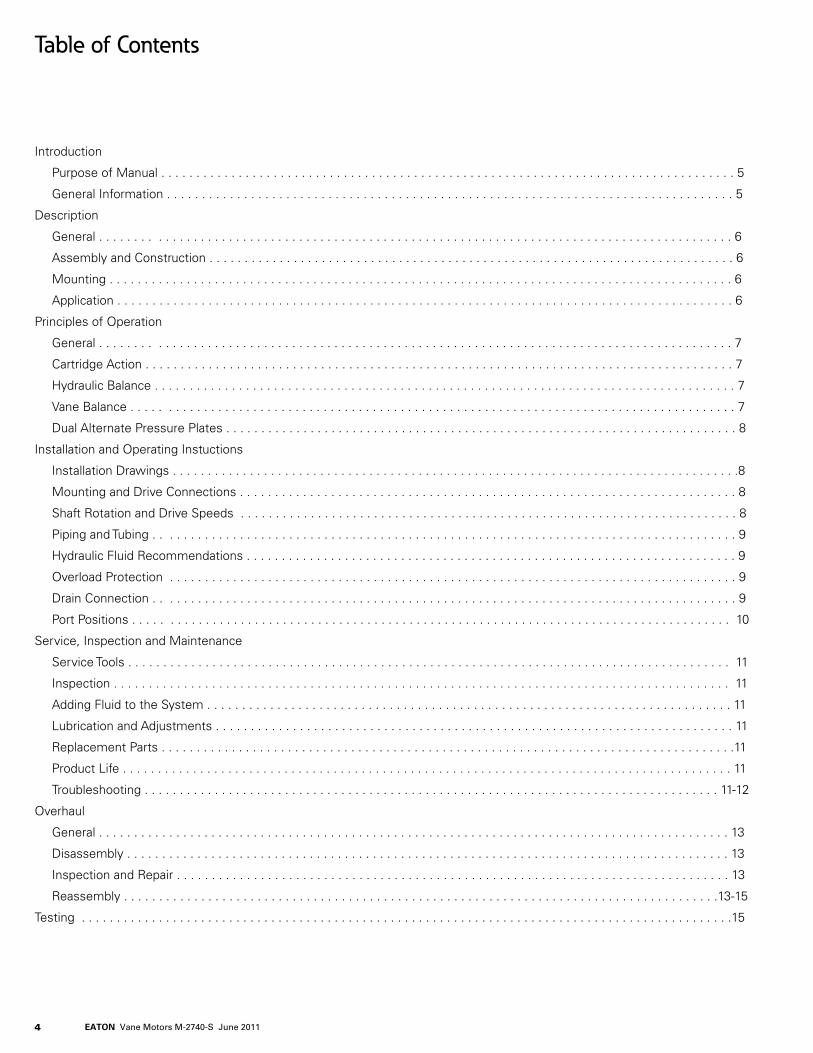
Introduction
Purpose of Manual . . . . . . . . . . . . . . . . . . . . . . . . . . . . . . . . . . . . . . . . . . . . . . . . . . . . . . . . . . . . . . . . . . . . . . . . . . . . . . . . . . 5
General Information . . . . . . . . . . . . . . . . . . . . . . . . . . . . . . . . . . . . . . . . . . . . . . . . . . . . . . . . . . . . . . . . . . . . . . . . . . . . . . . . . 5
Description
General . . . . . . . . . . . . . . . . . . . . . . . . . . . . . . . . . . . . . . . . . . . . . . . . . . . . . . . . . . . . . . . . . . . . . . . . . . . . . . . . . . . . . . . . . . 6
Assembly and Construction . . . . . . . . . . . . . . . . . . . . . . . . . . . . . . . . . . . . . . . . . . . . . . . . . . . . . . . . . . . . . . . . . . . . . . . . . . . 6
Mounting . . . . . . . . . . . . . . . . . . . . . . . . . . . . . . . . . . . . . . . . . . . . . . . . . . . . . . . . . . . . . . . . . . . . . . . . . . . . . . . . . . . . . . . . . 6
Application . . . . . . . . . . . . . . . . . . . . . . . . . . . . . . . . . . . . . . . . . . . . . . . . . . . . . . . . . . . . . . . . . . . . . . . . . . . . . . . . . . . . . . . . 6
Principles of Operation
General . . . . . . . . . . . . . . . . . . . . . . . . . . . . . . . . . . . . . . . . . . . . . . . . . . . . . . . . . . . . . . . . . . . . . . . . . . . . . . . . . . . . . . . . . . 7
Cartridge Action . . . . . . . . . . . . . . . . . . . . . . . . . . . . . . . . . . . . . . . . . . . . . . . . . . . . . . . . . . . . . . . . . . . . . . . . . . . . . . . . . . . . 7
Hydraulic Balance . . . . . . . . . . . . . . . . . . . . . . . . . . . . . . . . . . . . . . . . . . . . . . . . . . . . . . . . . . . . . . . . . . . . . . . . . . . . . . . . . . . 7
Vane Balance . . . . . . . . . . . . . . . . . . . . . . . . . . . . . . . . . . . . . . . . . . . . . . . . . . . . . . . . . . . . . . . . . . . . . . . . . . . . . . . . . . . . . . 7
Dual Alternate Pressure Plates . . . . . . . . . . . . . . . . . . . . . . . . . . . . . . . . . . . . . . . . . . . . . . . . . . . . . . . . . . . . . . . . . . . . . . . . . 8
Installation and Operating Instuctions
Installation Drawings . . . . . . . . . . . . . . . . . . . . . . . . . . . . . . . . . . . . . . . . . . . . . . . . . . . . . . . . . . . . . . . . . . . . . . . . . . . . . . . . .8
Mounting and Drive Connections . . . . . . . . . . . . . . . . . . . . . . . . . . . . . . . . . . . . . . . . . . . . . . . . . . . . . . . . . . . . . . . . . . . . . . . 8
Shaft Rotation and Drive Speeds . . . . . . . . . . . . . . . . . . . . . . . . . . . . . . . . . . . . . . . . . . . . . . . . . . . . . . . . . . . . . . . . . . . . . . . 8
Piping and Tubing . . . . . . . . . . . . . . . . . . . . . . . . . . . . . . . . . . . . . . . . . . . . . . . . . . . . . . . . . . . . . . . . . . . . . . . . . . . . . . . . . . . 9
Hydraulic Fluid Recommendations . . . . . . . . . . . . . . . . . . . . . . . . . . . . . . . . . . . . . . . . . . . . . . . . . . . . . . . . . . . . . . . . . . . . . . 9
Overload Protection . . . . . . . . . . . . . . . . . . . . . . . . . . . . . . . . . . . . . . . . . . . . . . . . . . . . . . . . . . . . . . . . . . . . . . . . . . . . . . . . . 9
Drain Connection . . . . . . . . . . . . . . . . . . . . . . . . . . . . . . . . . . . . . . . . . . . . . . . . . . . . . . . . . . . . . . . . . . . . . . . . . . . . . . . . . . . 9
Port Positions . . . . . . . . . . . . . . . . . . . . . . . . . . . . . . . . . . . . . . . . . . . . . . . . . . . . . . . . . . . . . . . . . . . . . . . . . . . . . . . . . . . . . 10
Service, Inspection and Maintenance
Service Tools . . . . . . . . . . . . . . . . . . . . . . . . . . . . . . . . . . . . . . . . . . . . . . . . . . . . . . . . . . . . . . . . . . . . . . . . . . . . . . . . . . . . . . 11
Inspection . . . . . . . . . . . . . . . . . . . . . . . . . . . . . . . . . . . . . . . . . . . . . . . . . . . . . . . . . . . . . . . . . . . . . . . . . . . . . . . . . . . . . . . . 11
Adding Fluid to the System . . . . . . . . . . . . . . . . . . . . . . . . . . . . . . . . . . . . . . . . . . . . . . . . . . . . . . . . . . . . . . . . . . . . . . . . . . . 11
Lubrication and Adjustments . . . . . . . . . . . . . . . . . . . . . . . . . . . . . . . . . . . . . . . . . . . . . . . . . . . . . . . . . . . . . . . . . . . . . . . . . . 11
Replacement Parts . . . . . . . . . . . . . . . . . . . . . . . . . . . . . . . . . . . . . . . . . . . . . . . . . . . . . . . . . . . . . . . . . . . . . . . . . . . . . . . . . .11
Product Life . . . . . . . . . . . . . . . . . . . . . . . . . . . . . . . . . . . . . . . . . . . . . . . . . . . . . . . . . . . . . . . . . . . . . . . . . . . . . . . . . . . . . . . 11
Troubleshooting . . . . . . . . . . . . . . . . . . . . . . . . . . . . . . . . . . . . . . . . . . . . . . . . . . . . . . . . . . . . . . . . . . . . . . . . . . . . . . . . . . 11-12
Overhaul
General . . . . . . . . . . . . . . . . . . . . . . . . . . . . . . . . . . . . . . . . . . . . . . . . . . . . . . . . . . . . . . . . . . . . . . . . . . . . . . . . . . . . . . . . . . 13
Disassembly . . . . . . . . . . . . . . . . . . . . . . . . . . . . . . . . . . . . . . . . . . . . . . . . . . . . . . . . . . . . . . . . . . . . . . . . . . . . . . . . . . . . . . 13
Inspection and Repair . . . . . . . . . . . . . . . . . . . . . . . . . . . . . . . . . . . . . . . . . . . . . . . . . . . . . . . . . . . . . . . . . . . . . . . . . . . . . . . 13
Reassembly . . . . . . . . . . . . . . . . . . . . . . . . . . . . . . . . . . . . . . . . . . . . . . . . . . . . . . . . . . . . . . . . . . . . . . . . . . . . . . . . . . . . .13-15
Testing . . . . . . . . . . . . . . . . . . . . . . . . . . . . . . . . . . . . . . . . . . . . . . . . . . . . . . . . . . . . . . . . . . . . . . . . . . . . . . . . . . . . . . . . . . . . .15
5EATON Vane Motors M-2740-S June 2011
Introduction
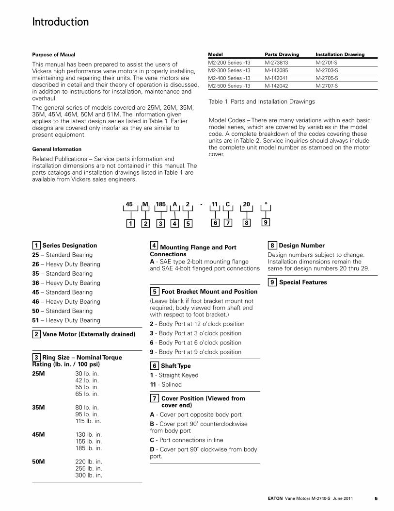
Purpose of Maual
This manual has been prepared to assist the users of Vickers high performance vane motors in properly installing, maintaining and repairing their units. The vane motors are described in detail and their theory of operation is discussed, in addition to instructions for installation, maintenance and overhaul.
The general series of models covered are 25M, 26M, 35M, 36M, 45M, 46M, 50M and 51M. The information given applies to the latest design series listed in Table 1. Earlier designs are covered only insofar as they are similar to present equipment.
General Information
Related Publications – Service parts information and installation dimensions are not contained in this manual. The parts catalogs and installation drawings listed in Table 1 are available from Vickers sales engineers.
Table 1. Parts and Installation Drawings
Model Codes – There are many variations within each basic model series, which are covered by variables in the model code. A complete breakdown of the codes covering these units are in Table 2. Service inquiries should always include the complete unit model number as stamped on the motor cover.
Model Parts Drawing Installation Drawing
M2-200 Series -13 M-273813 M-2701-SM2-300 Series -13 M-142085 M-2703-SM2-400 Series -13 M-142041 M-2705-SM2-500 Series -13 M-142042 M-2707-S
45 M 185 A 2 - 11 C 20 *
1 2 3 4 5 6 7 8 9
1 Series Designation
25 – Standard Bearing
26 – Heavy Duty Bearing
35 – Standard Bearing
36 – Heavy Duty Bearing
45 – Standard Bearing
46 – Heavy Duty Bearing
50 – Standard Bearing
51 – Heavy Duty Bearing
2 Vane Motor (Externally drained)
3 Ring Size – Nominal Torque Rating (lb. in. / 100 psi)
25M 30 lb. in. 42 lb. in. 55 lb. in. 65 lb. in. 35M 80 lb. in. 95 lb. in. 115 lb. in. 45M 130 lb. in. 155 lb. in. 185 lb. in. 50M 220 lb. in. 255 lb. in. 300 lb. in.
4 Mounting Flange and Port ConnectionsA - SAE type 2-bolt mounting flange and SAE 4-bolt flanged port connections
5 Foot Bracket Mount and Position
(Leave blank if foot bracket mount not required; body viewed from shaft end with respect to foot bracket.)
2 - Body Port at 12 o’clock position
3 - Body Port at 3 o’clock position
6 - Body Port at 6 o’clock position
9 - Body Port at 9 o’clock position
6 Shaft Type
1 - Straight Keyed
11 - Splined
7 Cover Position (Viewed from cover end)
A - Cover port opposite body port
B - Cover port 90˚ counterclockwise from body port
C - Port connections in line
D - Cover port 90˚ clockwise from body port.
8 Design Number
Design numbers subject to change.Installation dimensions remain the same for design numbers 20 thru 29.
9 Special Features

6 EATON Vane Motors M-2740-S June 2011
Description
General
Vickers high performance vane motors, when properly installed in a hydraulic circuit, convert hydraulic power into rotary mechanical power. They are positive-displacement, balanced cartridge units, with drive speed dependent on the motor size and gpm delivery to the inlet port. The units are capable of operating at high speeds and high pressures, or higher speeds at lower pressures. These motors may be operated in either direction of rotation, reversed or stalled under load conditions without damage.
All motors covered in this manual are basically identical in construction. The motors are designed so that the maximum torque capability can be changed within a series by changing the cartridge or the cam ring.
Assembly and Construction
Basic motor construction is illustrated in Figure 1. The unit consists principally of a body, cover, drive cartridge and shaft. Rotary motion is developed in the cartridge, which principally consists of a ring, rotor, ten vanes and two pressure plates. The rotor is splined and mates with the output shaft, which is supported by a ball bearing in the body and a bushing bearing in the cover pressure plate.
The vanes slide radially in the rotor slots and follow the elliptical cam contour of the ring as the rotor turns. These vanes are held against the ring by a combination of spring and centrifugal forces.
Port connections are located in the body and cover. Direction of shaft rotation is governed by the direction of fluid flow
through these ports. Pressure is sealed from one port to the other by a Teflon sealing ring in the body on the periphery of the ring. Drainage is ported through an external connection in the cover.
The cartridge is bolted together and can be serviced as a complete assembly. Locating pins position the ring with respect to the pressure plates, and in like manner, two torque pins position the cartridge in the cover. The cover can be assembled in four positions with respect to the body. Changing of the port positions is accomplished by rotating the cover and cartridge.
Mounting
The motors are body face mounted, or are available with an optional foot mounting (see Section IV). The body mounting is a standard SAE 2-bolt type.
Applications
Vickers high performance vane motors are rated in poundinches of torque per 100 psi. Horsepower output is proportional to drive speed so long as pressure is constant. For application information, refer to the appropriate installation drawing (Table 1) or consult Vickers application engineering personnel.
Figure 1. Cutaway View of Vane Motor.
Cover Port
Vane
Spring
Drain
Bushing
CoverPressure
Plate
Ring
Rotor
Body Pressure PlateBearing
Felt Wiper
Shaft
Shaft Seal
Hub Adaptor
Body Port
Teflon RingO-ring

7EATON Vane Motors M-2740-S June 2011
Principles of Operation
General
Rotation of the motor shaft is caused by differential pressure across the motor exerting a force against the vanes. This force is in effect tangential to the rotor and causes the rotor to turn, carrying the motor shaft with it.
If fluid is directed into the motor through the body port (see Figure 2), shaft rotation, as viewed from the shaft end, is clockwise. When the oil supply is directed to the cover port, rotation is counterclockwise, as viewed from the shaft end. Changing the direction of fluid flow thus changes the direction of motor rotation. This is usually accomplished by the use of a suitable directional control valve. With either port open to pressure, the other port becomes the return port.
Cartridge Action
Oil entering the inlet port (see Figure 2) is divided by internal coring and is directed into chambers between the vanes through kidney slots A and A1 (see Figure 3). The chambers between vane 1 and vane 3 are supplied with high-pressure oil from ports A and A1. The chambers between vane 3 and vane 5 are at a lower pressure because they are open to discharge ports B and B1 which are connected to the tank. This clockwise rotation of the rotor and vane assembly results from the difference in pressure across vane 3. The maximum pressure in ports A and A1 is a function of the load the motor must turn. It can be readily seen from Figure 3 that if the direction of flow is reversed, B and B1 will become pressure chambers and the direction of shaft rotation will be reversed.
Hydraulic Balance
Regardless of whether A and A1 or B and B1 are high-pressure chambers, equal pressure will always be present in any two chambers 180 degrees apart. Thus, hydraulic loads against the shaft cancel each other out and the unit is in hydraulic balance.
Vane Balance
The vanes are ported through radial holes so that pressure at the outer edges which are against the ring is essentially equal to the inner edges. Thus, the vanes are balanced hydraulically and are held out against the ring by a combination of spring and centrifugal forces.
Figure 2.
Cover Body
Drainto
tank
ClockwiseRotation
Cover Body
Drainto
tank
ClockwiseRotation
High PressureReturn Pressure
Operating Pressures
Figure 3.
High Pressure(Inlet Port)
Shaft rotationas viewed
from shaft endVane
Rotor
Spring
Ring
BB 1
A1
Return Pressure(Discharge Port)
A
Figure 2.
Cover Body
Drainto
tank
ClockwiseRotation
Cover Body
Drainto
tank
ClockwiseRotation
High PressureReturn Pressure
Operating Pressures
Figure 3.
High Pressure(Inlet Port)
Shaft rotationas viewed
from shaft endVane
Rotor
Spring
Ring
BB 1
A1
Return Pressure(Discharge Port)
A

8 EATON Vane Motors M-2740-S June 2011
Dual Alternate Pressure Plates
The cartridge side plates used in these motors are an exclusive dual-alternate pressure plate design (refer to Figure 4).
Two basically identical plates are used. The plate subjected to high pressure functions as the pressure plate. High pressure acting on the outer annulus of this plate moves the complete cartridge – ring, rotor and both plates – axially away from the high-pressure housing causing the cartridge to seat against the low-pressure housing (points ‘B’ in Figure 4). Construction of the plates is such that the lower pressurized\ plate contacts its housing on an annulus close to the axis of rotation.
Since the periphery of the low-pressure plate is not restrained from further movement, a load applied through the ring deflects it in the direction of the hydraulic load (points ‘A’). This action deflects that portion of the plate near the rotating axis inward towards the rotor face (points ‘B’). Thus, one side plate is deflected towards the rotor by high system pressure; the other plate is deflected towards the rotor as a result of peripheral mechanical loading plus the restraining action near its center.
This design concept results in low leakage rates and high operating efficiency. Also inherent in this design is the elimination of the shuttle valve arrangement found in conventional, dual-directional vane motors.
Installation and Operating InstructionsInstallation Drawings
The installation drawings listed in Table 1 show installation dimensions and port positions.
Mounting and Drive Connections
CAUTION
Motor shafts are designed to be installed in flexible couplings with a slip fit or very light press. Pounding
a coupling end onto the shaft can damage the bearings. Shaft tolerances are shown on the installation drawings. (See Table 1)
• Direct Drive. A pilot on the mounting flange (Figure 5) assures correct mounting and shaft alignment, provided the pilot is firmly seated in the accessory pad. Care should be exercised in tightening all flange mounting screws to prevent misalign-ment. This mounting is a standard SAE 2-bolt type. If gaskets are used between flanges, they should be installed carefully so as to lie flat. Shaft keys and couplings must be properly seated to avoid slipping and possible shearing. Proper coupling alignment is essential to prolong motor life.
• Indirect Drive. Belt, chain and gear drives can be used with certain models of these motors. Specific recommendations and data on limitations should be obtained from a Vickers sales engineer.
Shaft Rotation and Drive Speeds
Motors can be driven in either direction of rotation without changing their construction or assembly.
Normal operating speed can be as low as 50 to 100 rpm.Lower drive speeds depend on torque requirements and characteristics of the driven load. For operation below 50 rpm, consult a Vickers sales engineer.
•
Figure 4
PressurePlates
Pressure
PressureA
B
A
B
Figure 5
Pilot
Shaft

9EATON Vane Motors M-2740-S June 2011
Piping and Tubing
1. All pipes fittings, hose and tubing must be thoroughly cleaned before installation. Recommended methods of cleaning are sandblasting, wirebrushing and pickling.
NOTE: For instructions on pickling, refer to instruction sheet 1221-S.
2. To minimize flow resistance and the possibility of leakage, use only as many fittings and connections as necessary for proper installation.
3. The number of bends in hydraulic lines should be kept to a minimum to prevent excessive turbulence and friction of oil flow and to minimize pressure drop in the lines. Tubing must not be bent too sharply. The recommended radius for bends is three times the inside diameter of the tube.
Hydraulic Fluid Recommendations
General Data
Oil in a hydraulic system performs the dual function of lubrication and transmission of power. It constitutes a vital factor in a hydraulic system and careful selection of it should be made with the assistance of a reputable supplier. Proper selection of oil assures satisfactory life and operation of system components with particular emphasis on hydraulic motors. Any oil selected for use with motors is acceptable for use with valves or pumps.
Data sheets for oil selection are available from Vickers Technical Publications, Troy, Michigan. Order data sheet M-2950-S for mobile applications.
The oil recommendations noted in the data sheet are based on our experience in industry as a hydraulic component manufacturer.
Where special considerations indicate a need to depart from the recommended oils or operating conditions, see your Vickers representative.
Cleanliness
Clean fluid is the best insurance for long service life. To insure your hydraulic system is clean, perform the following steps.
1. Clean (flush) entire new system to remove paint, metal chips, welding shot, etc.
2. Filter each change of oil to prevent introduction of contaminants into the system.
3. Provide continuous oil filtration to remove sludge and products of wear and corrosion generated during the life of the system.
4. Provide continuous protection of system from entry of airborne contamination, by sealing the system and/or by proper filtration of the air.
5. Proper oil filling and servicing of filters, breathers, reservoirs, etc., cannot be overemphasized.
6. Good system and reservoir design will insure that aeration of the oil is kept to a minimum.
Sound Level
Noise is indirectly affected by the fluid selection, but the condition of the fluid is of paramount importance in obtaining optimum reduction of system sound levels.
Some of the major factors affecting fluid conditions that cause the loudest noises in a hydraulic system are:
1. Very high viscosities at start-up temperatures can cause motor noises due to cavitation.
2. Running with a moderately high viscosity fluid will slow the release of entrained air. The fluid will not be completely purged of such air in the time it remains in the reservoir and air will be recycled through the system.
3. Aerated fluid can also be caused by ingestion of air through the pipe joints of inlet lines, high velocity discharge lines, cylinder rod packings, or by fluid discharging above the fluid level in the reservoir. Air in the fluid causes a noise similar to cavitation.
4. Contaminated fluids can cause excessive wear of internal motor parts, which may result in increased sound levels.
Overload Protection
A relief valve must be installed in the system to limit pressure to a prescribed maximum. This protects the system components from excessive pressure. The setting of the relief valve depends on the work requirements of the system and the maximum pressure ratings of the system components. The relief protection must be designed to prevent any hydraulic surge pressure, whether applied to or generated by the motor, from exceeding the maximum pressure rating of the motor.
In the event of an overrunning load, the motor may be driven as a pump. If such a condition occurs, provision must be made in the circuit to supply the motor enough hydraulic fluid to prevent cavitation.
Drain Connection
Drain passages are provided in the motor to carry internal leakage to a drain port in the cover. Never operate the motor unless the drain port is connected to the reservoir. Pressure in the drain line must not be more than 30 psi to avoid internal damage.

10 EATON Vane Motors M-2740-S June 2011
Port Positions
Covers can be assembled in four positions with respect to bodies, as shown in Figure 6. To change the relative location of the ports, it is necessary only to remove the four cover bolts and rotate the cover to the desired position. cover bolts must be tightened to the torque specified in Figure 10 at reassembly.
Foot Bracket Mounting And Body Model Code Position (Viewed From Shaft End)
2 Body Port at 12 o’clock Position3 Body Port at 3 o’clock Position6 Body Port at 6 o’clock Position9 Body Port at 9 o’clock Position
Cover Port Position Model Code (Viewed From Cover End)
A Cover Port Opposite Body PortB Cover Port 90 Counterclockwise from Body PortC Port Connections In LineD Cover Port 90 Clockwise from Body Port
Figure 6.
Body Port
Cover Port
A
B
C
D
2
3
6
9

11EATON Vane Motors M-2740-S June 2011
Service, Inspection and Maintenance
Service Tools
Special tools required for these units are shaft seal drivers and adapter extractor tool. The seal drivers can be made from round stock machined as shown in Figure 7.
The recess in the tool will be deep enough so uniform pressure is applied to the recessed area in the seal channel rather than on the seal lip. The outside diameter of the tool will not interfere with the spring around the seal lip.
The adapter extractor tool is designed to remove the hub adapter from the body after the cartridge is removed (see Figure 8). The extractor tool engages between the ball bearing and the hub adapter.
Inspection
Periodic inspection of oil condition and tubing connections can save time-consuming breakdowns and unnecessary parts replacement. The following should be checked regularly.
1. All hydraulic connections must be kept tight. A loose connection in a pressure line will permit the fluid to leak out. Loose connections in other lines can permit air
to be drawn into the system, resulting in noisy and/or erratic operation.
2. Clean fluid is the best insurance for long service life. Therefore, the reservoir should be checked periodically for dirt or other contaminants. If the fluid becomes contaminated, the system should be thoroughly drained and the reservoir cleaned before new fluid is added.
3. Filter elements also should be checked and replaced periodically. A clogged filter element results in a higher pressure drop. This can force particles through the filter which would ordinarily be trapped, or can cause the bypass to open, resulting in a partial or complete loss of filtration.
4. Air bubbles in the reservoir can ruin the motor and other components. If bubbles are seen, locate the source of the air and seal the leak.
Adding Fluid To The System
When hydraulic fluid is added to replenish the system, it should always be poured through a fine wire screen (200 mesh or finer).
It is important that the fluid be clean and free of any substance which could cause improper operation or wear of the motor or other hydraulic units. Therefore, the use of cloth to strain the fluid should be avoided to prevent lint from getting into the system.
Lubrication and Adjustments
Internal lubrication is provided by system oil flow. No periodic adjustments are required, other than to maintain proper shaft alignment with the driving medium.
Replacement Parts
Reliable operation throughout the specified operating range is assured only if genuine Vickers parts are used. Part numbers are shown in the parts drawings listed in Table 1.
Product Life
The longevity of these products is dependent upon environment, duty cycle, operating parameters and system cleanliness. Since these parameters vary from application to application, the ultimate user must determine and establish the periodic maintenance required to maximize life and detect potential component failure.
Troubleshooting
Table 5 lists the common difficulties experienced with vane motors and hydraulic systems. It also indicates the probable causes and remedies for each of the troubles listed.
It should always be remembered that many apparent motor failures are actually due to the failure of other parts of the system. The cause of improper operation is best diagnosed with adequate testing equipment and a thorough understand-ing of the complete hydraulic system.
5.000
A
CB
Radius Blend
Figure 7.
Figure 8.
Z
Z
.12R
1.38
.63
.19
.388.50
6.56.63
.81
Adapter Extractor Tool(14 gauge – SAE 1040 stock)
.50 R.56 R
.81
1.00
5.000
A
CB
Radius Blend
Figure 7.
Figure 8.
Z
Z
.12R
1.38
.63
.19
.388.50
6.56.63
.81
Adapter Extractor Tool(14 gauge – SAE 1040 stock)
.50 R.56 R
.81
1.00
Dimension Motor Size A B C
25M-20 .312 1.375 1.46835M-20 .312 1.687 1.78145M-20 .437 1.906 2.21850M-20 .437 2.166 2.348
NOTE: All dimensions in inches

12 EATON Vane Motors M-2740-S June 2011
Trouble Probable Cause Remedy
System leakage – loose port connections or Inspect and tighten port connections and lines. broken lines. No fluid – inadequate fluid supply at inlet or in Check fluid level in reservoir. Replenish as system. necessary. System return line or drain line restricted. Check drain filter. Clean and/or replace filter element. Fluid viscosity to heavy to pick up prime. Check all strainers and filter for dirt and sludge. Clean if necessary. Air in system. Tighten any lose connections. Bleed air from highest point in system and replenish fluid. Drive train damaged. Check and repair drive train. Motor driven in wrong direction. Drive direction must be reversed immediately to prevent seizure. Motor coupling or shaft sheared. Check shaft engagement and damage. Replace the necessary parts. Motor binding. Remove and disassemble the unit. Check for correct assembly of parts. also check for dirt or metal chips. clean the parts thoroughly and replace any damaged parts. Insufficient motor speed. Check motor drive speed. Insufficient fluid pressure. Check delivery of motor. Make certain sufficient hydraulic fluid is available to the motor. System overload relief valve set too low. Check pressure and reset relief valve. Motor requiring excessive torque. Remove motor and check torque requirements of drive shaft. Parts of motor cartridge scored due to Remove motor for overhaul. excessive pressure or foreign matter in oil. Improper port connections or control. Reverse port connections or shift valve. Components in system not functioning as intended. Check complete system for proper operation. Air in system. Bleed air from highest point in system and replenish fluid. Motor internally damaged. Remove motor for overhaul. Noise from other system components telegraphing Check complete system for proper operation. back through lines and emerging from motor. External Leakage from motor. Worn seals or cut o-rings. Install new seals and o-rings.Motor shaft continuing to rotate when Control valve is not functioning properly. Check control valve for correct spool and control is in ‘off’ position. leakage.
Motor noisy.
Motor turning in wrong direction.
Motor not developing sufficient speed or torque.
Motor fails to start.
Table 5. Troubleshooting Chart

13EATON Vane Motors M-2740-S June 2011
Overhaul
General
Plug all removed units and cap all lines to prevent the entry of dirt into the system during shutdown. During disassembly, pay particular attention to identification of the parts for correct assembly.
Figure 10 is an exploded view which shows the proper relationship of the parts for disassembly and assembly. Figure 1 can be referred to for the correct assembled relationship.
NOTE: Pre-assembled replacement cartridges are available for rapid field overhaul of these motors. If a replacement cartridge is being used, proceed as in step B-1 following for disassembly and step D-7 and D-8 for reassembly.
Disassembly
1. Cover End. Clamp the motor in a vise with protective jaws, cover end up.
Remove the four cover bolts and lift off the cover. Remove the cartridge from the body. If the cartridge is not being replaced as an assembly, remove two screws and separate the pressure plates from the rotor, ring, vanes and springs.
NOTE: Use a standard piston ring compressor of suitable size when disassembling and assembling the cartridge components.
Carefully pull the rotor and vane assembly half way out of ring and install the ring compressor (see Figure 9). Compress the vanes into the rotor and remove this assembly from ring. Release the ring compressor and disassemble components. Remove the o-ring and back-up rings from the pressure plate and body.
2. Shaft End. Remove the shaft key. Carefully pull the hub adapter from the body with the adapter puller tool (see Figure 8). Remove spirolox ring next to the shaft bearing from the body, then tap the shaft and bearing assembly out. If it is necessary to remove the small snap ring and bearing from the shaft, support the bearing inner race in an arbor press, remove snap ring and press bearing off the shaft. Remove washer and then shaft seal and wiper from the body.
Inspection and Repair
1. Discard the shaft seal, wiper, o-rings and back-up rings. Use a new seal kit for reassembly (see parts catalog). Wash the metal parts in clean petroleum solvent, blow them dry with filtered compressed air and place on a clean surface for inspection.
2. Check for wearing surfaces of the cartridge pressure plates and ring for scoring and wear. Replace any scored or worn parts.
3. Inspect the vanes for burrs, wear and excessive play in the rotor slots. Carefully remove burrs with a medium India stone (Norton abrasives MF724 knife type stone for flat surfaces and MF214 round type stones with 60 conical ends for inside corners). Replace the rotor if the slots are worn. Replace vanes with a new vane and spring kit if the vane tips are worn.
4. Rotate the bearing on the shaft while applying pressure to check for wear, looseness, roughness and pitted or cracked races.
5. Inspect the seal and bushing mating surfaces on the shaft for scoring or wear. Replace the shaft if marks cannot be removed by light polishing.
6. Be sure that any paint or burrs raised on the body and cover mating surfaces are removed before reassembly.
Reassembly
NOTE: Coat all parts with clean hydraulic fluid to facilitate reassembly and provide initial lubrication. Use small amounts of petroleum jelly to hold the o-rings in place during assembly. Soak the shaft wiper in oil before reassembly.
1. Shaft Seal Assembly. Install the shaft wiper in the body. Grease the shaft seal and press it into the body with the seal driver (Figure 7). The spring on the shaft seal must be toward the bearing. Place the washer in the body against the shaft seal.
2. Shaft Assembly. Support the bearing inner race and press in the shaft. Install the tru-arc snap ring on the shaft. Lightly tap the shaft and bearing assembly into the body with a plastic hammer. Install the spirolox ring in the body to secure the bearing and shaft. Thoroughly inspect to insure that spirolox ring is correctly installed.
3. Cartridge Assembly. With the rotor lying on a clean, flat surface, slide the vanes and springs into the rotor slots. Lift the vanes slightly to insure the springs are positioned in the spring recesses of the rotor. With a piston ring compressor of suitable size, compress the vanes in the slots so the vanes will clear the minor diameter of the ring (Figure 9).
CAUTION
Be certain the springs remain seated in the spring recesses of the rotor as vanes are compressed.
•
Figure 9.
Piston RingCompressor
Rotor
Vane
Ring

14 EATON Vane Motors M-2740-S June 2011
Figure 10.
Torque Table25M-20 35M-2045M-2050M-20
Torque Table25M-20 35M-20 45M-2050M-20
Back-upRing
O-ring
O-ring
RetainingRing
RetainingRing
Lock Ring
Bearing
Shaft #11
Key
ShaftSeal
Bolt
Retainer
Wiper
Body
MountingBracket
DrainOpening
Cover
Screw
Back-upRing
O-ringPressure PlateSub-Assembly
(including bushing)
Rotor
Vanes
Springs
O-ringBack-up
Ring
HubAdapter
PressurePlate
RingCartridge
Pin
Bolt
Shaft #1
2 - 4 lb. ft.
8 - 12 lb. ft.
18 - 24 lb. ft.
95 - 150 lb. ft.190 - 210 lb. ft.
290 - 310 lb. ft.355 - 375 lb. ft.

15EATON Vane Motors M-2740-S June 2011
4. Vanes and Rotor. Position the ring on a flat surface and insert the rotor and vane assembly 1/4 way into the ring. Use a suitable size hard wood plug as a driver for positioning the rotor and vane assembly (see Table 5). Release the compressor carefully so the vanes do not snap out against the ring surface. With the hard wood plug, press the vanes and rotor flush with the ring.
NOTE: Vanes may become cocked if not pushed down uniformly.
5. Cartridge Pins. Install the cartridge pins on the body end pressure plate (plate without bushing). Place the rotor, ring and vane assembly over the pins on the plate.
6. Cover End Pressure Plate. Install the cover end pressure plate against the rotor and ring. The porting in this plate will be 90 degrees from the other plate. Carefully install the two cap screws in the cartridge. Tighten the screws
to values shown in Figure 9 being certain the peripheral edges of the ring and plates are flush. Tap with a plastic hammer if necessary to effect alignment.
7. O-Rings and Back-Up Rings. Install backup rings first and then o-rings on the pressure plate hubs. Grease with petroleum jelly. Inspect this assembly to insure that the o-ring is positioned in the concave side of the back-up ring.
8. Cartridge Installation. Clamp the body in a vise with protective jaws. Assemble the hub adapter on the cartridge pressure plate (body end). Install back-up ring and then the o-ring on the hub adapter. Grease with petroleum. Install the cartridge on the shaft, with the hub adapter toward the body. Tap the cartridge into position. Install the retaining ring in the body.
9. Cover Assembly. Install the o-ring in the cover, greasing liberally. Carefully install the cover, being sure the locating pin engages the pin hole in the cover. To check engagement, turn the cover 30 degrees in both directions and be certain the cartridge moves with it. Install four cover bolts and tighten requirement shown in Figure 9.
Testing
If test equipment is available, the motor should be tested at the recommended speeds and pressures shown on the installation drawings (Table 1).
Motor Size Diameter Approx. Length
25M-20 2.80 1.5035M-20 3.36 2.0045M-20 3.95 2.5050M-20 4.50 2.75
Table 5. Rotor Driver Dimensions

Eaton Hydraulics Group USA14615 Lone Oak RoadEden Prairie, MN 55344USATel: 952-937-9800Fax: 952-294-7722www.eaton.com/hydraulics
Eaton Hydraulics Group EuropeRoute de la Longeraie 71110 MorgesSwitzerlandTel: +41 (0) 21 811 4600Fax: +41 (0) 21 811 4601
Eaton Hydraulics Group Asia PacificEaton Building4th Floor, No. 3 Lane 280 Linhong Rd. Changning DistrictShanghai 200335ChinaTel: (+86 21) 5200 0099Fax: (+86 21) 5200 0400
© 2011 Eaton Corporation All Rights Reserved Printed in USA Document No. M-2740-S June 2011


