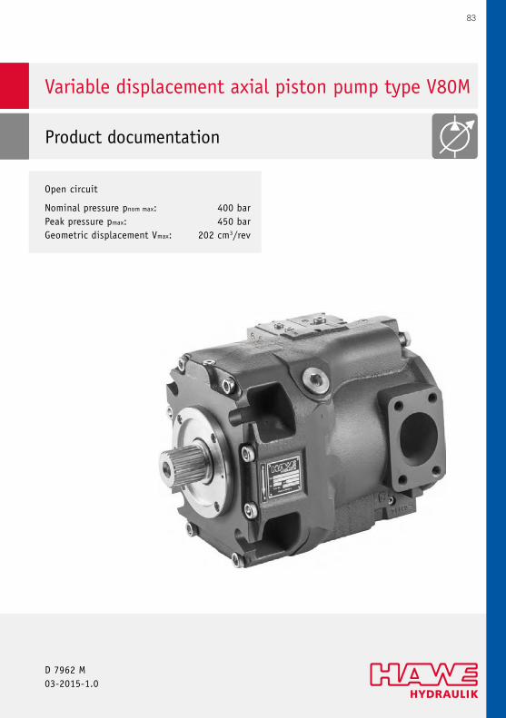
Variable displacement axial piston pump type V80M Product documentation D 7962 M 03-2015-1.0 Open circuit Nominal pressure pnom max: 400 bar Peak pressure pmax: 450 bar Geometric displacement Vmax: 202 cm 3 /rev 83
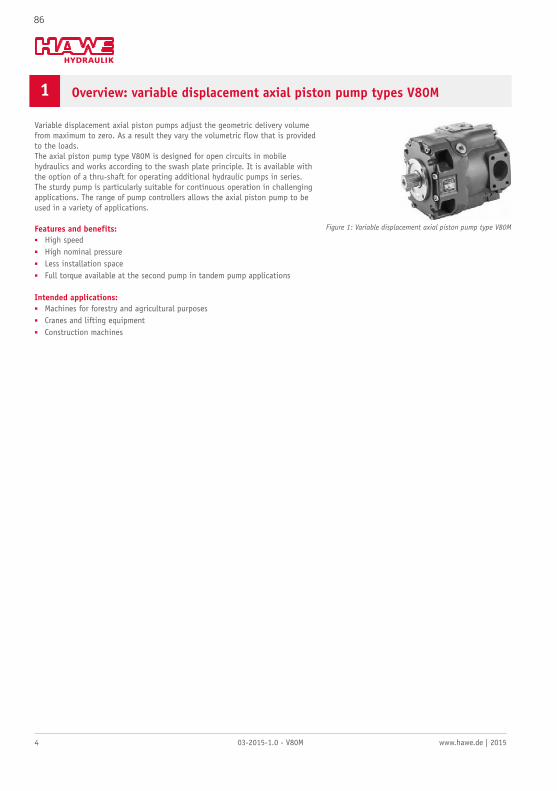
Variable displacement axial piston pumps adjust the geometric delivery volumefrom maximum to zero. As a result they vary the volumetric flow that is providedto the loads.The axial piston pump type V80M is designed for open circuits in mobilehydraulics and works according to the swash plate principle. It is available withthe option of a thru-shaft for operating additional hydraulic pumps in series.The sturdy pump is particularly suitable for continuous operation in challengingapplications. The range of pump controllers allows the axial piston pump to beused in a variety of applications.
Features and benefits:■ High speed■ High nominal pressure■ Less installation space■ Full torque available at the second pump in tandem pump applications
Intended applications:■ Machines for forestry and agricultural purposes■ Cranes and lifting equipment■ Construction machines
Figure 1: Variable displacement axial piston pump type V80M
86
www.hawe.de | 2015 03-2015-1.0 - V80M 5
2 Available versions, main data
2.1 Basic version
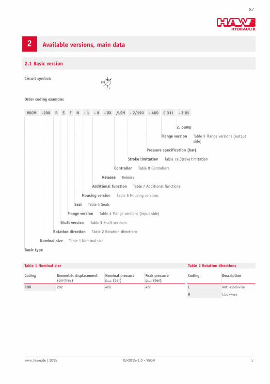
Circuit symbol:
Order coding example:
V80M -200 R S F N - 1 - 0 - XX /LSN - 2/190 - 400 C 311 - Z 05
2. pump
Flange version Table 9 Flange versions (outputside)
Pressure specification (bar)
Stroke limitation Table 7a Stroke limitation
Controller Table 8 Controllers
Release Release
Additional function Table 7 Additional functions
Housing version Table 6 Housing versions
Seal Table 5 Seals
Flange version Table 4 Flange versions (input side)
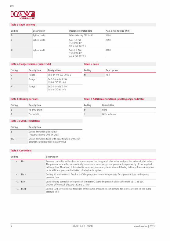
-... N - Pressure controller with adjustable pressure on the integrated pilot valve and port for external pilot valve.The pressure controller automatically maintains a constant system pressure independently of the requireddelivery flow. Therefore, it is suited to constant pressure systems where differing delivery flows are requiredor for efficient pressure limitation of a hydraulic system.
-... Nb - Coding Nb with external feedback of the pump pressure to compensate for a pressure loss in the pumppressure line.
-... LSN Load-sensing controller with pressure limitation. Stand-by pressure adjustable from 15 ... 35 bar.Default differential pressure setting: 27 bar
-... LSNb Coding LSNb with external feedback of the pump pressure to compensate for a pressure loss in the pumppressure line.
88
www.hawe.de | 2015 03-2015-1.0 - V80M 7
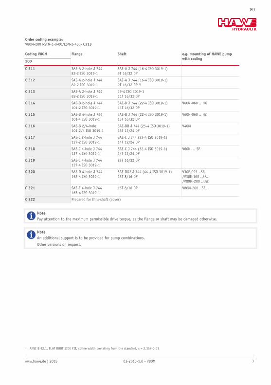
Order coding example:V80M-200 RSFN-1-0-00/LSN-2-400- C313
Coding V80M
200
Flange Shaft e.g. mounting of HAWE pumpwith coding
C 311 SAE-A 2-hole J 74482-2 ISO 3019-1
SAE-A J 744 (16-4 ISO 3019-1)9T 16/32 DP
C 312 SAE-A 2-hole J 74482-2 ISO 3019-1
SAE-A J 744 (16-4 ISO 3019-1)9T 16/32 DP 1)
C 313 SAE-A 2-hole J 74482-2 ISO 3019-1
19-4 ISO 3019-111T 16/32 DP
C 314 SAE-B 2-hole J 744101-2 ISO 3019-1
SAE-B J 744 (22-4 ISO 3019-1)13T 16/32 DP
V60N-060 .. HX
C 315 SAE-B 4-hole J 744101-4 ISO 3019-1
SAE-B J 744 (22-4 ISO 3019-1)13T 16/32 DP
V60N-060 .. HZ
C 316 SAE-B 2/4-hole101-2/4 ISO 3019-1
SAE-BB J 744 (25-4 ISO 3019-1)15T 12/24 DP
V40M
C 317 SAE-C 2-hole J 744127-2 ISO 3019-1
SAE-C J 744 (32-4 ISO 3019-1)14T 12/24 DP
C 318 SAE-C 4-hole J 744127-4 ISO 3019-1
SAE-C J 744 (32-4 ISO 3019-1)14T 12/24 DP
V60N- .. SF
C 319 SAE-C 4-hole J 744127-4 ISO 3019-1
23T 16/32 DP
C 320 SAE-D 4-hole J 744152-4 ISO 3019-1
SAE-D&E J 744 (44-4 ISO 3019-1)13T 8/16 DP
V30E-095 ..SF../V30E-160 ..SF../V80M-200 ..UW..
C 321 SAE-E 4-hole J 744165-4 ISO 3019-1
15T 8/16 DP V80M-200 ..SF..
C 322 Prepared for thru-shaft (cover)
NotePay attention to the maximum permissible drive torque, as the flange or shaft may be damaged otherwise.
NoteAn additional support is to be provided for pump combinations.
Other versions on request.
1) ANSI B 92.1, FLAT ROOT SIDE FIT, spline width deviating from the standard, s = 2.357-0.03
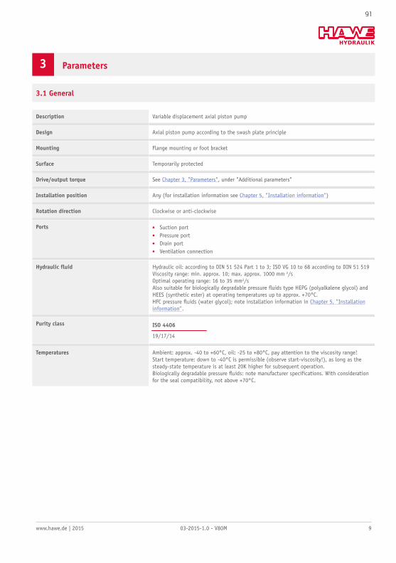
Hydraulic fluid Hydraulic oil: according to DIN 51 524 Part 1 to 3; ISO VG 10 to 68 according to DIN 51 519Viscosity range: min. approx. 10; max. approx. 1000 mm 2/sOptimal operating range: 16 to 35 mm2/sAlso suitable for biologically degradable pressure fluids type HEPG (polyalkalene glycol) andHEES (synthetic ester) at operating temperatures up to approx. +70°C.HFC pressure fluids (water glycol); note installation information in Chapter 5, "Installationinformation".
Purity class ISO 4406
19/17/14
Temperatures Ambient: approx. -40 to +60°C, oil: -25 to +80°C, pay attention to the viscosity range!Start temperature: down to -40°C is permissible (observe start-viscosity!), as long as thesteady-state temperature is at least 20K higher for subsequent operation.Biologically degradable pressure fluids: note manufacturer specifications. With considerationfor the seal compatibility, not above +70°C.
91
10 03-2015-1.0 - V80M www.hawe.de | 2015
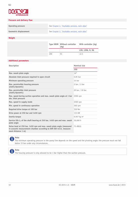
Pressure and delivery flow
Operating pressure See Chapter 2, "Available versions, main data"
Geometric displacement See Chapter 2, "Available versions, main data"
Weight
Type V80M Without controller(kg)
With controller (kg)
LSN, LSNb, N, Nb
200 93 +2.5
Additional parameters
Nominal sizeDescription
200
Max. swash plate angle 16°
Absolute inlet pressure required in open circuit 0.85 bar
Minimum operating pressure 15 bar
Max. permissible housing pressure(static/dynamic)
2 bar / 3 bar
Max. permissible inlet pressure(static/dynamic)
20 bar / 30 bar
Max. speed during suction operation and max. swash plate angle at 1 barabs. Inlet pressure
2200 rpm
Max. speed in supply mode 2500 rpm
Min. speed in continuous operation 500 rpm
Required drive torque at 100 bar 350 Nm
Drive power at 250 bar and 1450 rpm 133 kW
Inertia torque 0.057 kg m2
Service life Lh of the shaft bearing at 250 bar, 1450 rpm and max. swashplate angle
20,000 h
Noise level at 250 bar, 1450 rpm and max. swash plate angle (measuredin acoustic measurement chamber according to DIN ISO 4412, measure-ment distance 1 m)
75 dB(A)
NoteThe minimum operating pressure in the pump line depends on the speed and the pivoting angle; the pressure must not fallbelow 15 bar under any circumstances.
NoteThe housing pressure is only allowed to be 1 bar higher than the suction pressure.
92
www.hawe.de | 2015 03-2015-1.0 - V80M 11
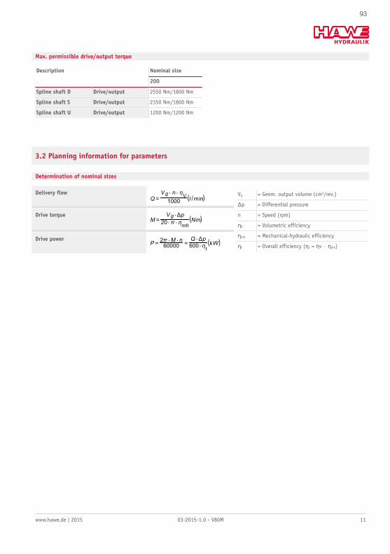
Max. permissible drive/output torque
Nominal sizeDescription
200
Spline shaft D Drive/output 2550 Nm/1800 Nm
Spline shaft S Drive/output 2350 Nm/1800 Nm
Spline shaft U Drive/output 1200 Nm/1200 Nm
3.2 Planning information for parameters
Determination of nominal sizes
Delivery flow
Drive torque
Drive power
Vg = Geom. output volume (cm3/rev.)
Δp = Differential pressure
n = Speed (rpm)
ηV = Volumetric efficiency
ηmh = Mechanical-hydraulic efficiency
ηt = Overall efficiency (ηt = ηv · ηmh)
93
12 03-2015-1.0 - V80M www.hawe.de | 2015
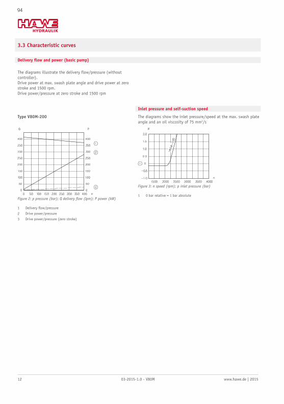
3.3 Characteristic curves
Delivery flow and power (basic pump)
The diagrams illustrate the delivery flow/pressure (withoutcontroller).Drive power at max. swash plate angle and drive power at zerostroke and 1500 rpm.Drive power/pressure at zero stroke and 1500 rpm
Inlet pressure and self-suction speed
Type V80M-200 The diagrams show the inlet pressure/speed at the max. swash plateangle and an oil viscosity of 75 mm2/s
Figure 2: p pressure (bar); Q delivery flow (lpm); P power (kW)
1 Delivery flow/pressure
2 Drive power/pressure
3 Drive power/pressure (zero stroke)
Figure 3: n speed (rpm); p inlet pressure (bar)
1 0 bar relative = 1 bar absolute
94
www.hawe.de | 2015 03-2015-1.0 - V80M 13
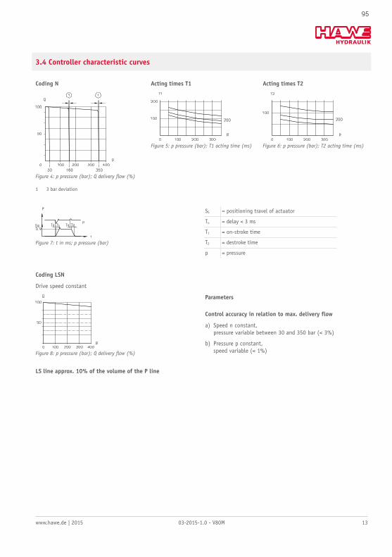
3.4 Controller characteristic curves
Coding N Acting times T1 Acting times T2
Figure 4: p pressure (bar); Q delivery flow (%)
1 3 bar deviation
Figure 5: p pressure (bar); T1 acting time (ms) Figure 6: p pressure (bar); T2 acting time (ms)
Figure 7: t in ms; p pressure (bar)
SS = positioning travel of actuator
Tu = delay < 3 ms
T1 = on-stroke time
T2 = destroke time
p = pressure
Coding LSN
Drive speed constant
Figure 8: p pressure (bar); Q delivery flow (%)
Parameters
Control accuracy in relation to max. delivery flow
a) Speed n constant,pressure variable between 30 and 350 bar (< 3%)
b) Pressure p constant,speed variable (< 1%)
LS line approx. 10% of the volume of the P line
95
14 03-2015-1.0 - V80M www.hawe.de | 2015
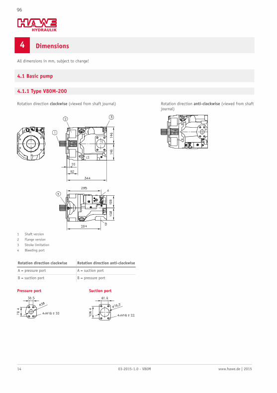
4 Dimensions
All dimensions in mm, subject to change!
4.1 Basic pump
4.1.1 Type V80M-200
Rotation direction clockwise (viewed from shaft journal) Rotation direction anti-clockwise (viewed from shaftjournal)
1 Shaft version
2 Flange version
3 Stroke limitation
4 Bleeding port
Rotation direction clockwise Rotation direction anti-clockwise
A = pressure port A = suction port
B = suction port B = pressure port
Pressure port Suction port
96
www.hawe.de | 2015 03-2015-1.0 - V80M 15
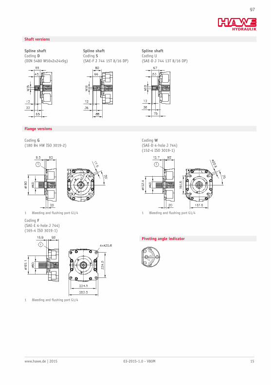
Shaft versions
Spline shaftCoding D(DIN 5480 W50x2x24x9g)
Spline shaftCoding S(SAE-F J 744 15T 8/16 DP)
Spline shaftCoding U(SAE-D J 744 13T 8/16 DP)
Flange versions
Coding G(180 B4 HW ISO 3019-2)
Coding W(SAE-D 4-hole J 744)(152-4 ISO 3019-1)
1 Bleeding and flushing port G1/4 1 Bleeding and flushing port G1/4
Coding F(SAE-E 4-hole J 744)(165-4 ISO 3019-1)
1 Bleeding and flushing port G1/4
Pivoting angle indicator
97
16 03-2015-1.0 - V80M www.hawe.de | 2015
5 Installation information
5.1 General information
The type V80M pumps are suitable for use in an open circuit.
It can be mounted using a flange in accordance with specifications.
The various controllers can be fitted as separate devices as required.
The following essential points must be noted when installing the pump:
Mounting and removal of the pump and attached components may be performed by trained persons only. Ensure absolute cleanlinessduring all work. Contamination may have an adverse effect on the function and service life of the pump.
■ Remove all plastic plugs prior to initial operation.■ Avoid installing the motor above the tank (see Chapter 5.3, "Installation positions").■ Observe the reference values in Section .■ Prior to initial operation, fill the pump with oil and bleed. Automatic pump filling via the suction line by opening the drain ports is
not possible.■ Prevent the pump and suction line from running dry.■ Always ensure a constant supply of oil. Even a brief shortage in the supply of hydraulic fluid to the pump may damage internal parts.
This may not be immediately evident after initial operation.■ The hydraulic oil returning to the tank from the system must not be sucked back in immediately (baffles).■ Run the pump for approx. 10 minutes at max. 50 bar after initial operation.■ Thorough bleeding/flushing of the entire system is recommended before the full pressure range is used.■ Observe the max. permissible operating range temperatures (see Chapter 3, "Parameters") at all times.■ Always comply with the specified oil purity classes (see Chapter 3, "Parameters"); provide appropriate hydraulic fluid filtering.■ Use of a filter in the intake line must be approved by HAWE Hydraulik.■ Include a main pressure-limiting valve in the pressure line to limit the max. system pressure.
98
www.hawe.de | 2015 03-2015-1.0 - V80M 17
5.2 Ports
The nominal diameter of the connecting lines depends on the specified operating conditions, the viscosity of the hydraulic fluid, thestart-up and operating temperatures and the speed of the pump. In principle we recommend the use of hose lines due to the superiordamping characteristics.
Bleeding and flushing port
The pump type V80M is fitted with a G 1/4" (BSPP) bleeding and flushing port. This is used to bleed and flush the front shaft bearing inthe case of vertical installation.
Pressure port
The pressure port connection is established in the case of type V80M via SAE ports, see Chapter 4, "Dimensions". Metric attachmentthreads are used in deviation from the standard.
Observe the tightening torque specified by the fitting manufacturer.
Suction port
The suction port can be established via SAE ports; see Chapter 4, "Dimensions". Metric attachment threads are used in deviation fromthe standard.
If possible, route the suction line to the tank in such a way that it is steadily rising. This allows trapped air to escape. Observe thespecifications in "Installation positions "Chapter 5.3, "Installation positions". The absolute suction pressure must not fall below 0.85bar. A hose line should generally be used in preference to a rigid pipe.
Drain port
The Pump type V80M has 2 drain ports G 1" (BSPP).
The nominal diameter of the leakage line must not be less than 16 mm. The cross-section is determined by the max. permissible housingpressure.
Integrate the leakage line in the system in such a way as to prevent direct connection with the suction line of the pump.
All drain ports can be used simultaneously.
A separate leakage line from the controller to the tank is not required. Observe the specifications in Chapter 5.3, "Installationpositions".
The top drain port can be used to fill the housing.
LS port for version LSN
The LS line is connected to the controller via a G 1/4" (BSPP) threaded connection.
The nominal diameter of the line depends on the installation position of the pump and should be 10% of the pressure line capacity. Ahose line should generally be used in preference to a rigid pipe.
■ When the proportional directional spool valve is in a neutral position, the LS line must be fully relieved (only controller type LSNR,LSN). In the case of controller type LSNRT, relief takes place internally in the controller.
99
18 03-2015-1.0 - V80M www.hawe.de | 2015
5.3 Installation positions
The pump type V80M can be installed in any installation position.
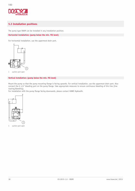
Horizontal installation: (pump below the min. fill level)
For horizontal installation, use the uppermost drain port.
1 suction port open
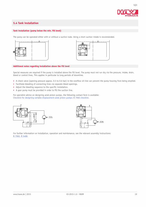
Vertical installation: (pump below the min. fill level)
Mount the pump so that the pump mounting flange is facing upwards. For vertical installation, use the uppermost drain port. Alsoconnect the G 1/4" bleeding port on the pump flange. Take appropriate measures to ensure continuous bleeding of this line (linerouting/bleeding).For installation with the pump flange facing downwards, please contact HAWE Hydraulik.
1 suction port open
100
www.hawe.de | 2015 03-2015-1.0 - V80M 19
5.4 Tank installation
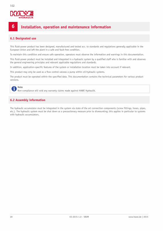
Tank installation (pump below the min. fill level)
The pump can be operated either with or without a suction tube. Using a short suction intake is recommended.
Additional notes regarding installation above the fill level
Special measures are required if the pump is installed above the fill level. The pump must not run dry via the pressure, intake, drain,bleed or control lines. This applies in particular to long periods of downtime.
■ A check valve (opening pressure approx. 0.5 to 0.6 bar) in the overflow oil line can prevent the pump housing from being emptied.■ Facilitate bleeding of connecting lines via separate bleed openings.■ Adjust the bleeding sequence to the specific installation.■ A gear pump must be provided in order to fill the suction line.
For specialist advice on designing axial piston pumps, the following contact form is available:Checklist for designing variable displacement axial piston pumps: B 7960 checklist.
For further information on installation, operation and maintenance, see the relevant assembly instructions:B 7960, B 5488.
101
20 03-2015-1.0 - V80M www.hawe.de | 2015
6 Installation, operation and maintenance information
6.1 Designated use
This fluid-power product has been designed, manufactured and tested acc. to standards and regulations generally applicable in theEuropean Union and left the plant in a safe and fault-free condition.
To maintain this condition and ensure safe operation, operators must observe the information and warnings in this documentation.
This fluid-power product must be installed and integrated in a hydraulic system by a qualified staff who is familiar with and observesthe general engineering principles and relevant applicable regulations and standards.
In addition, application-specific features of the system or installation location must be taken into account if relevant.
This product may only be used as a flow control valveas a pump within oil-hydraulic systems.
The product must be operated within the specified data. This documentation contains the technical parameters for various productversions.
NoteNon-compliance will void any warranty claims made against HAWE Hydraulik.
6.2 Assembly information
The hydraulic accumulator must be integrated in the system via state of the art connection components (screw fittings, hoses, pipes,etc.). The hydraulic system must be shut down as a precautionary measure prior to dismounting; this applies in particular to systemswith hydraulic accumulators.
102
www.hawe.de | 2015 03-2015-1.0 - V80M 21
6.3 Operating instructions
Product, pressure and/or flow settings
All statements in this documentation must be observed for all product, pressure and/or flow settings on or in the hydraulic system.
CautionRisk of injury on overloading components due to incorrect pressure settings!■ Always monitor the pressure gauge when setting or changing the pressure.
CautionRisk of injury due to unexpected movement processes in the machine due to incorrect flow setting!On changing the flow settings loads will move more slowly or more quickly.The consequence can be unexpected movements.
■ Only make flow settings or changes in a controlled manner!
Filtering and purity of the hydraulic fluid
Soiling in the fine range, e.g. abraded material and dust, or in the macro range, e.g. chips, rubber particles from hoses and seals, cancause significant malfunctions in a hydraulic system. It is also to be noted that new hydraulic fluid “from the drum” does not necessari-ly meet the highest purity requirements.
For trouble-free operation pay attention to the purity of the hydraulic fluid (see also purity class in Chapter 3, "Parameters").
6.4 Maintenance information
This product is largely maintenance-free.
Check that the product is securely fastened in the mounting hole at regular intervals, but at least once per year.
Conduct a visual inspection to check the hydraulic connections for damage at regular intervals, but at least once per year. If externalleaks are found, shut down and remedy.
Check the device surfaces for dust deposits at regular intervals (but at least annually) and clean the device if required.
■ General operating manual for the assembly, initial operation and maintenance of hydraulic components and systems: B 5488■ Variable displacement axial piston pump type V60N: D 7960 N■ Variable displacement axial piston pump type V40M: D 7961■ Variable displacement axial piston pump type V30D: D 7960■ Fixed displacement axial piston pump type K60N: D 7960 K■ Axial piston motors type M60N: D 7960 M■ Variable displacement axial piston pump type V30E: D 7960 E■ Proportional directional spool valve type EDL: D 8086■ Proportional directional spool valve, type PSL and PSV size 2: D 7700-2■ Proportional directional spool valve, type PSL, PSM and PSV size 3: D 7700-3■ Proportional directional spool valve, type PSL, PSM and PSV size 5: D 7700-5■ Proportional directional spool valve type PSLF, PSVF and SLF size 3: D 7700-3F■ Proportional directional spool valve type PSLF, PSVF and SLF size 5: D 7700-5F■ Proportional directional spool valve banks, type PSLF, PSVF and SLF size 7: D 7700-7F■ Load-holding valve type LHT: D 7918■ Load-holding valve type LHDV: D 7770■ Proportional amplifier type EV1M3: D 7831/2■ Proportional amplifier type EV1D: D 7831 D