251
Vauxhall Meriva Owner's Manual
Vauxhall MerivaOwner's Manual

Introduction .................................... 2In brief ............................................ 6Keys, doors and windows ............ 19Seats, restraints ........................... 34Storage ........................................ 60Instruments and controls ............. 80Lighting ...................................... 119Climate control ........................... 128Driving and operating ................. 138Vehicle care ............................... 170Service and maintenance .......... 219Technical data ........................... 222Customer information ................ 237Index .......................................... 244
Contents
2 Introduction
Introduction
Introduction 3
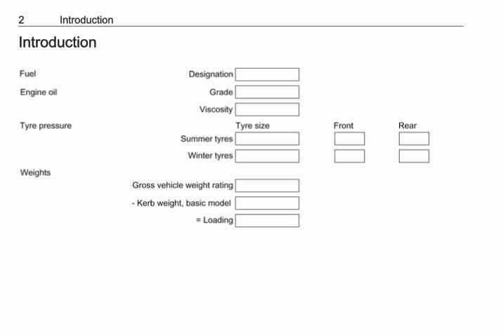
Vehicle specific dataPlease enter your vehicle's data onthe previous page to keep it easilyaccessible. This information isavailable in the sections "Service andmaintenance" and "Technical data"as well as on the identification plate.
IntroductionYour vehicle is a designedcombination of advanced technology,safety, environmental friendlinessand economy.This Owner's Manual provides youwith all the necessary information toenable you to drive your vehiclesafely and efficiently.Make sure your passengers areaware of the possible risk of accidentand injury which may result fromimproper use of the vehicle.You must always comply with thespecific laws and regulations of thecountry that you are in. These lawsmay differ from the information in thisOwner's Manual.Disregarding the description given inthis manual may affect your warranty.
When this Owner's Manual refers to aworkshop visit, we recommend yourVauxhall Authorised Repairer. Forgas vehicles, we recommend aVauxhall Authorised Repairerlicensed to service gas vehicles.All Vauxhall Authorised Repairersprovide first-class service atreasonable prices. Experiencedmechanics trained by Vauxhall workaccording to specific Vauxhallinstructions.The customer literature pack shouldalways be kept ready to hand in thevehicle.
Using this manual● This manual describes all options
and features available for thismodel. Certain descriptions,including those for display andmenu functions, may not apply toyour vehicle due to modelvariant, country specifications,special equipment oraccessories.
● The "In brief" section will give youan initial overview.
● The table of contents at thebeginning of this manual andwithin each section shows wherethe information is located.
● The index will enable you tosearch for specific information.
● This Owner's Manual depicts left-hand drive vehicles. Operation issimilar for right-hand drivevehicles.
● The Owner's Manual uses theengine identifier code. Thecorresponding sales designationand engineering code can befound in the section "Technicaldata".
● Directional data, e.g. left or right,or front or back, always relate tothe direction of travel.
● Displays may not support yourspecific language.
● Display messages and interiorlabelling are written in boldletters.
4 Introduction
Danger, Warnings andCautions
9 Danger
Text marked 9 Danger providesinformation on risk of fatal injury.Disregarding this information mayendanger life.
9 Warning
Text marked 9 Warning providesinformation on risk of accident orinjury. Disregarding thisinformation may lead to injury.
Caution
Text marked Caution providesinformation on possible damage tothe vehicle. Disregarding thisinformation may lead to vehicledamage.
SymbolsPage references are indicated with 3.3 means "see page".Page references and index entriesrefer to the indented headings givenin the section table of content.Thank you for choosing a Vauxhall.We wish you many hours ofpleasurable driving.Your Vauxhall Team

Introduction 5
6 In brief
In brief
Initial drive information
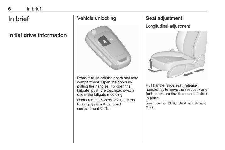
Vehicle unlocking
Press c to unlock the doors and loadcompartment. Open the doors bypulling the handles. To open thetailgate, push the touchpad switchunder the tailgate moulding.Radio remote control 3 20, Centrallocking system 3 22, Loadcompartment 3 26.
Seat adjustmentLongitudinal adjustment
Pull handle, slide seat, releasehandle. Try to move the seat back andforth to ensure that the seat is lockedin place.Seat position 3 36, Seat adjustment3 37.
In brief 7
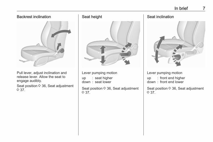
Backrest inclination
Pull lever, adjust inclination andrelease lever. Allow the seat toengage audibly.Seat position 3 36, Seat adjustment3 37.
Seat height
Lever pumping motionup : seat higherdown : seat lower
Seat position 3 36, Seat adjustment3 37.
Seat inclination
Lever pumping motionup : front end higherdown : front end lower
Seat position 3 36, Seat adjustment3 37.
8 In brief
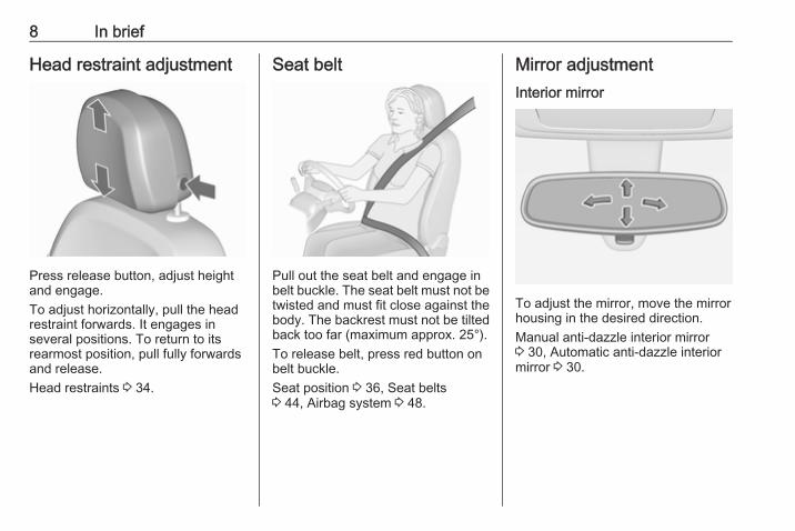
Head restraint adjustment
Press release button, adjust heightand engage.To adjust horizontally, pull the headrestraint forwards. It engages inseveral positions. To return to itsrearmost position, pull fully forwardsand release.Head restraints 3 34.
Seat belt
Pull out the seat belt and engage inbelt buckle. The seat belt must not betwisted and must fit close against thebody. The backrest must not be tiltedback too far (maximum approx. 25°).To release belt, press red button onbelt buckle.Seat position 3 36, Seat belts3 44, Airbag system 3 48.
Mirror adjustmentInterior mirror
To adjust the mirror, move the mirrorhousing in the desired direction.Manual anti-dazzle interior mirror3 30, Automatic anti-dazzle interiormirror 3 30.
In brief 9
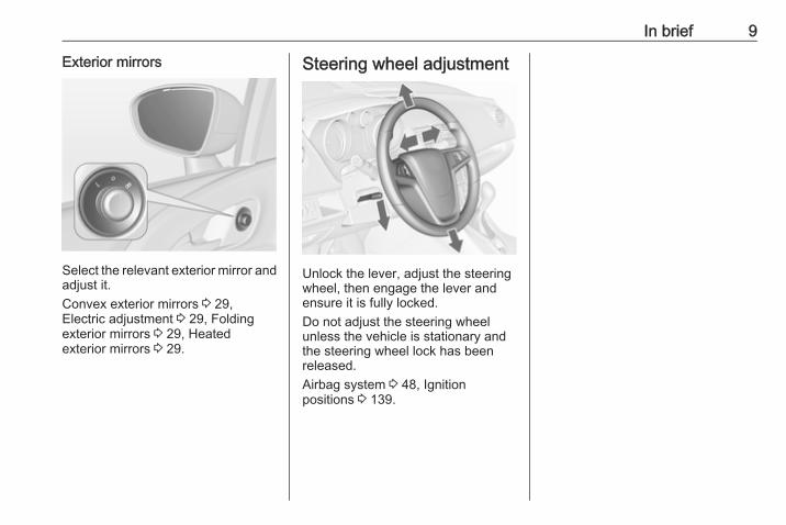
Exterior mirrors
Select the relevant exterior mirror andadjust it.Convex exterior mirrors 3 29,Electric adjustment 3 29, Foldingexterior mirrors 3 29, Heatedexterior mirrors 3 29.
Steering wheel adjustment
Unlock the lever, adjust the steeringwheel, then engage the lever andensure it is fully locked.Do not adjust the steering wheelunless the vehicle is stationary andthe steering wheel lock has beenreleased.Airbag system 3 48, Ignitionpositions 3 139.
10 In brief
Instrument panel overview
In brief 11
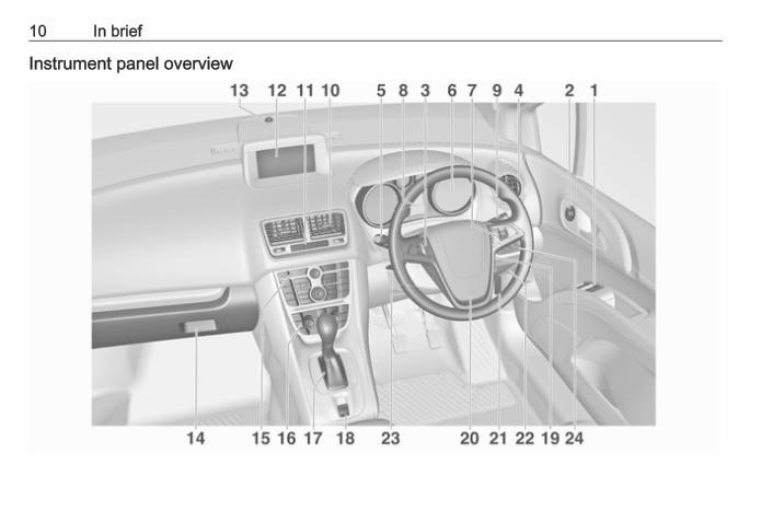
1 Power windows ..................... 312 Exterior mirrors ..................... 293 Cruise control ..................... 1534 Side air vents ...................... 1355 Turn and lane-change
signals, headlight flash,low beam and high beam ... 123
Exit lighting ......................... 126
Parking lights ...................... 124
Driver Information Centre .... 1006 Instruments .......................... 887 Steering wheel controls ....... 818 Driver Information Centre .... 1009 Windscreen wiper,
windscreen washersystem, rear wiper, rearwasher system ..................... 82
10 Centre air vents .................. 13511 Central locking system .......... 22
Hazard warning flashers .... 123
Control indicator for airbagdeactivation .......................... 94
12 Info-Display ......................... 103
13 Sensor for electronicclimate control system ....... 131
14 Glovebox .............................. 60
Fuse box ............................ 19215 Traction Control system ..... 152
Electronic Stability Control . 152
Ultrasonic parking assist .... 155
Eco button ........................... 141
Fuel selector ......................... 8916 Climate control system ........ 12817 Selector lever, manual
transmission ....................... 148
Automatic transmission ...... 14518 Electric parking brake ......... 15019 Ignition switch with
steering wheel lock ............ 13920 Horn ..................................... 82
Driver airbag ........................ 5121 Bonnet release lever .......... 17222 Storage compartment ........... 6023 Steering wheel adjustment . . 81
24 Light switch ........................ 119
Headlight rangeadjustment ......................... 121
Front fog lights ................... 123
Rear fog light ...................... 124
Instrument illumination ....... 125
12 In brief
Exterior lighting
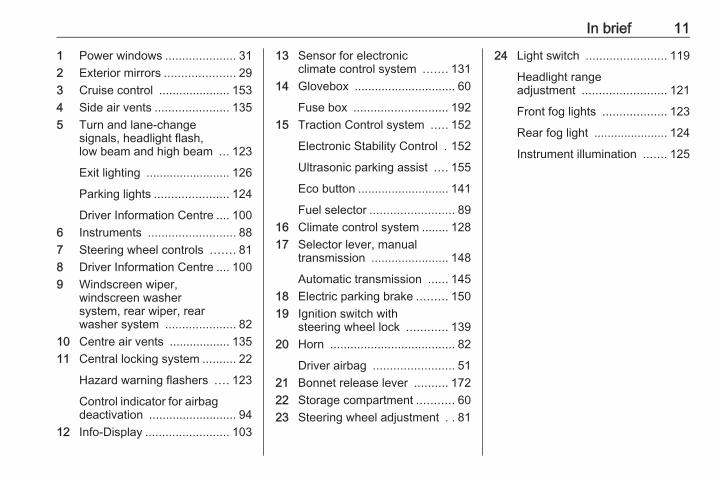
Turn light switch:7 : lights off8 : sidelights9 : low beam
Automatic light controlAUTO : automatic light control:
exterior lighting is switchedon and off automatically
m : activation or deactivation ofthe automatic light control
8 : sidelights9 : low beam
Fog lightsPress light switch> : front fog lightsr : rear fog light
Lighting 3 119.
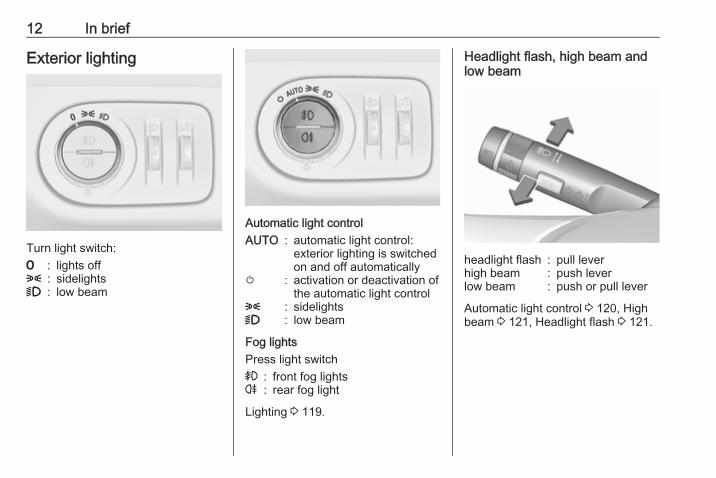
Headlight flash, high beam andlow beam
headlight flash : pull leverhigh beam : push leverlow beam : push or pull lever
Automatic light control 3 120, Highbeam 3 121, Headlight flash 3 121.
In brief 13
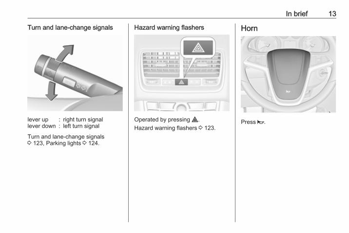
Turn and lane-change signals
lever up : right turn signallever down : left turn signal
Turn and lane-change signals3 123, Parking lights 3 124.
Hazard warning flashers
Operated by pressing ¨.Hazard warning flashers 3 123.
Horn
Press j.

14 In brief
Washer and wiper systemsWindscreen wiper
HI : fastLO : slowINT : interval wiping or automatic
wiping with rain sensorOFF : off
For a single wipe when thewindscreen wiper is off, press thelever down to position 1x.Windscreen wiper 3 82, Wiperblade replacement 3 178.
Windscreen washer
Pull lever.Windscreen washer system 3 82,Washer fluid 3 175.
Rear window wiper
Press the rocker switch to activate therear window wiper:upper switch : continuous
operationlower switch : intermittent
operationmiddle position : off
In brief 15
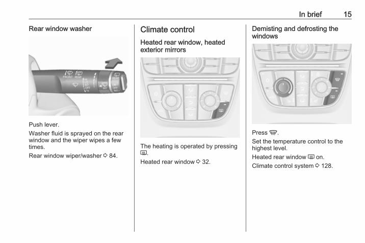
Rear window washer
Push lever.Washer fluid is sprayed on the rearwindow and the wiper wipes a fewtimes.Rear window wiper/washer 3 84.
Climate controlHeated rear window, heatedexterior mirrors
The heating is operated by pressingÜ.Heated rear window 3 32.
Demisting and defrosting thewindows
Press V.Set the temperature control to thehighest level.Heated rear window Ü on.Climate control system 3 128.

16 In brief
TransmissionManual transmission
Reverse: with the vehicle stationary,depress clutch pedal, press therelease button on the selector leverand engage the gear.If the gear does not engage, set thelever to neutral, release the clutchpedal and depress again; then repeatgear selection.Manual transmission 3 148.
Automatic transmission
P : parkR : reverseN : neutralD : drive
Manual mode: move selector leverfrom D to the left.< : higher gear] : lower gear
The selector lever can only be movedout of P when the ignition is on andthe brake pedal is applied. To engageP or R, press the release button.Automatic transmission 3 145.
Starting offCheck before starting off● Tyre pressure and condition
3 196, 3 234.● Engine oil level and fluid levels
3 173.● All windows, mirrors, exterior
lighting and number plates arefree from dirt, snow and ice andare operational.
● Proper position of mirrors, seats,and seat belts 3 29, 3 36,3 45.
● Brake function at low speed,particularly if the brakes are wet.

In brief 17
Starting the engine
● Turn key to position 1.● Move the steering wheel slightly
to release the steering wheellock.
● Operate clutch and brake.● Automatic transmission in P or N.● Do not operate accelerator pedal.● Diesel engines: turn the key to
position 2 for preheating and waituntil control indicator !extinguishes.
● Turn key to position 3 andrelease.
Starting the engine 3 140.
Stop-start system
If the vehicle is at a low speed or at astandstill and certain conditions arefulfilled, activate an Autostop asfollows:● Depress the clutch pedal.● Set the lever in neutral.● Release the clutch pedal.
An Autostop is indicated by theneedle at the AUTOSTOP position inthe tachometer.To restart the engine, depress theclutch pedal again.Stop-start system 3 141.
Parking
9 Warning
● Do not park the vehicle on aneasily ignitable surface. Thehigh temperature of theexhaust system could ignite thesurface.
● Always apply parking brake.Pull switch m for approx.one second.The electric parking brake isapplied when control indicatorm illuminates 3 95.
● Switch off the engine.● If the vehicle is on a level
surface or uphill slope, engagefirst gear or set the selectorlever to position P beforeremoving the ignition key. Onan uphill slope, turn the frontwheels away from the kerb.If the vehicle is on a downhillslope, engage reverse gear orset the selector lever to positionP before removing the ignition
18 In brief
key. Turn the front wheelstowards the kerb.
● Close the windows.● Remove the ignition key from
the ignition switch. Turn thesteering wheel until thesteering wheel lock is felt toengage.For vehicles with automatictransmission, the key can onlybe removed when the selectorlever is in position P.
● Lock the vehicle by pressing e onthe radio remote control.
● Activate the anti-theft alarmsystem 3 27.
● The engine cooling fans may runafter the engine has beenswitched off 3 172.
Caution
After running at high enginespeeds or with high engine loads,operate the engine briefly at a lowload or run in neutral for
approx. 30 seconds beforeswitching off, in order to protectthe turbocharger.
Keys, locks 3 19, Laying the vehicleup for a long period of time 3 171.

Keys, doors and windows 19
Keys, doors andwindows
Keys, locks ................................... 19Keys .......................................... 19Car Pass .................................... 20Radio remote control ................. 20Memorised settings ................... 21Central locking system .............. 22Automatic locking ...................... 24Child locks ................................. 25
Doors ........................................... 26Rear doors ................................. 26Load compartment .................... 26
Vehicle security ............................ 27Anti-theft locking system ........... 27Anti-theft alarm system .............. 27Immobiliser ................................ 28
Exterior mirrors ............................ 29Convex shape ........................... 29Electric adjustment .................... 29Folding mirrors .......................... 29Heated mirrors ........................... 29
Interior mirrors ............................. 30Manual anti-dazzle .................... 30Automatic anti-dazzle ................ 30
Windows ...................................... 30Windscreen ............................... 30Manual windows ........................ 31Power windows ......................... 31Heated rear window .................. 32Sun visors .................................. 33
Roof ............................................. 33Moonroof ................................... 33
Keys, locksKeys
Caution
Do not attach heavy or bulky itemsto the ignition key.
Replacement keysThe key number is specified in theCar Pass or on a detachable tag.The key number must be quotedwhen ordering replacement keys as itis a component of the immobilisersystem.Locks 3 215.The code number of the adapter forthe locking wheel bolts is specified ona card. It must be quoted whenordering a replacement adapter.Wheel changing 3 206.
20 Keys, doors and windows
Lock cylindersDesigned to free-wheel if they areforcefully rotated without the correctkey or if the correct key is not fullyinserted. To reset, turn cylinder withthe correct key until its slot is vertical,remove key and then re-insert it. If thecylinder still free-wheels, turn the keythrough 180° and repeat operation.
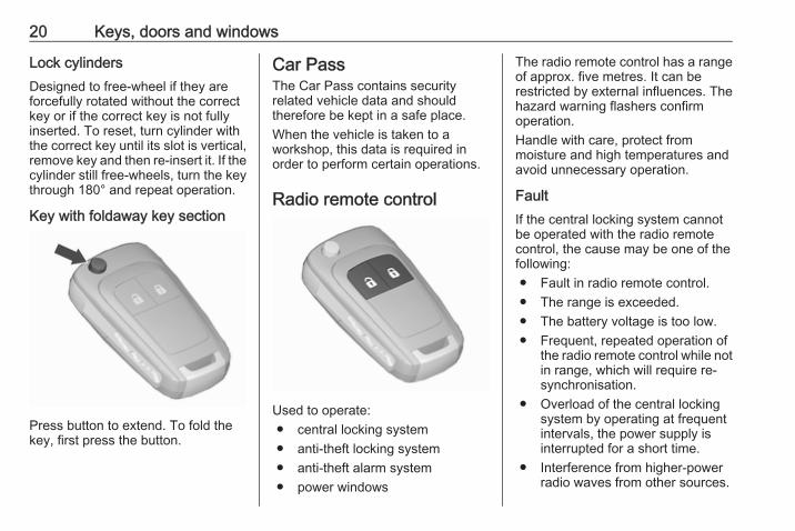
Key with foldaway key section
Press button to extend. To fold thekey, first press the button.
Car PassThe Car Pass contains securityrelated vehicle data and shouldtherefore be kept in a safe place.When the vehicle is taken to aworkshop, this data is required inorder to perform certain operations.
Radio remote control
Used to operate:● central locking system● anti-theft locking system● anti-theft alarm system● power windows
The radio remote control has a rangeof approx. five metres. It can berestricted by external influences. Thehazard warning flashers confirmoperation.Handle with care, protect frommoisture and high temperatures andavoid unnecessary operation.
FaultIf the central locking system cannotbe operated with the radio remotecontrol, the cause may be one of thefollowing:● Fault in radio remote control.● The range is exceeded.● The battery voltage is too low.● Frequent, repeated operation of
the radio remote control while notin range, which will require re-synchronisation.
● Overload of the central lockingsystem by operating at frequentintervals, the power supply isinterrupted for a short time.
● Interference from higher-powerradio waves from other sources.

Keys, doors and windows 21
Unlocking 3 22.
Basic settingsSome settings can be changed in themenu Settings in the Info-Display.Vehicle personalisation 3 111.
Radio remote control batteryreplacementReplace the battery as soon as therange is reduced.
Batteries do not belong in householdwaste. They must be disposed of atan appropriate recycling collectionpoint.
Key with foldaway key section
Extend the key and open the unit.Replace the battery (battery typeCR 2032), paying attention to theinstallation position. Close the unitand synchronise.
Key with fixed key sectionHave the battery replaced by aworkshop.
Radio remote controlsynchronisationAfter replacing the battery, unlock thedoor with the key in the driver's doorlock. The radio remote control will besynchronised when the ignition isswitched on.
Memorised settingsWhenever the key is removed fromthe ignition switch, the followingsettings are automatically memorisedby the key:● lighting● Infotainment system (only
CD 400)● central locking system● comfort settings
The saved settings are automaticallyused the next time the memorised keyis inserted into the ignition switch andturned to position 1 3 139.A precondition is that Personalizationby driver is activated in the personalsettings of the Graphic-Info-Display.This must be set for each key used.On vehicles equipped with
22 Keys, doors and windows
Colour-Info-Display, thepersonalisation is permanentlyactivated.Vehicle personalisation 3 111.
Central locking systemUnlocks and locks doors, loadcompartment and fuel filler flap.A pull on an interior door handleunlocks the respective door. Pullingthe handle once more opens the door.NoticeIn the event of an accident in whichairbags or belt pretensioners aredeployed, the vehicle isautomatically unlocked.
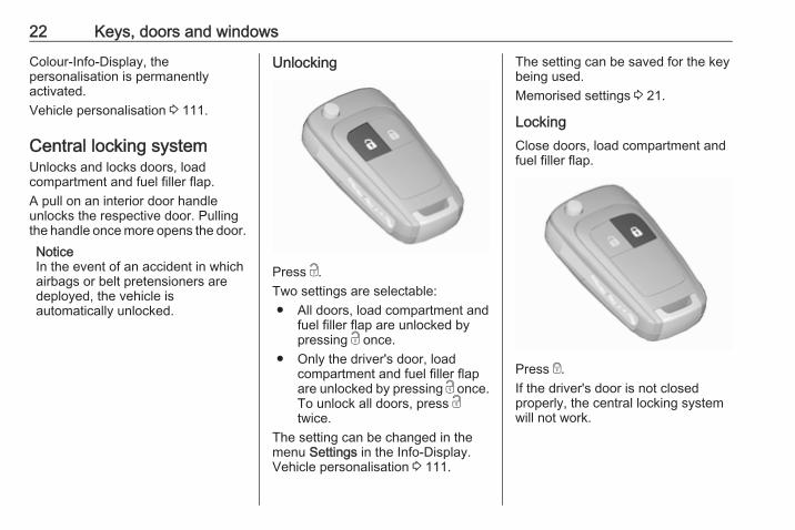
Unlocking
Press c.Two settings are selectable:● All doors, load compartment and
fuel filler flap are unlocked bypressing c once.
● Only the driver's door, loadcompartment and fuel filler flapare unlocked by pressing c once.To unlock all doors, press ctwice.
The setting can be changed in themenu Settings in the Info-Display.Vehicle personalisation 3 111.
The setting can be saved for the keybeing used.Memorised settings 3 21.
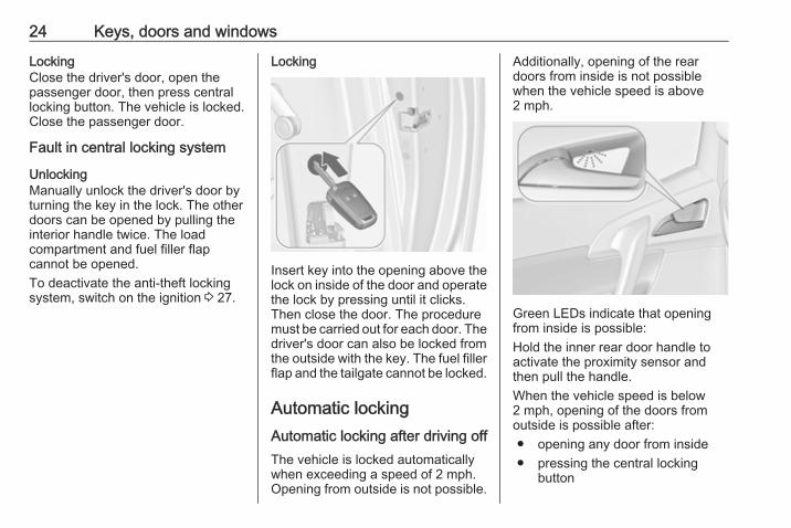
LockingClose doors, load compartment andfuel filler flap.
Press e.If the driver's door is not closedproperly, the central locking systemwill not work.

Keys, doors and windows 23
Unlocking and opening thetailgate
Press c when the ignition is off tounlock all doors. The tailgate isreleased and is unlocked and openedby pushing the touchpad switch underthe tailgate moulding.
Central locking buttonLocks or unlocks all doors, the loadcompartment and fuel filler flap fromthe passenger compartment.
Press central locking button: thedoors are locked or unlocked. If thedoors are locked, the LED in thebutton illuminates.After locking with the radio remotecontrol, the LED in the buttonilluminates for approx. 2 minutes.
Fault in radio remote controlsystem
Unlocking
Manually unlock the driver's door byturning the key in the lock. Switch onthe ignition and press the centrallocking button to unlock all doors,load compartment and fuel filler flap.By switching on the ignition, the anti-theft locking system is deactivated3 27.
24 Keys, doors and windows
LockingClose the driver's door, open thepassenger door, then press centrallocking button. The vehicle is locked.Close the passenger door.
Fault in central locking system
UnlockingManually unlock the driver's door byturning the key in the lock. The otherdoors can be opened by pulling theinterior handle twice. The loadcompartment and fuel filler flapcannot be opened.To deactivate the anti-theft lockingsystem, switch on the ignition 3 27.
Locking
Insert key into the opening above thelock on inside of the door and operatethe lock by pressing until it clicks.Then close the door. The proceduremust be carried out for each door. Thedriver's door can also be locked fromthe outside with the key. The fuel fillerflap and the tailgate cannot be locked.
Automatic lockingAutomatic locking after driving offThe vehicle is locked automaticallywhen exceeding a speed of 2 mph.Opening from outside is not possible.
Additionally, opening of the reardoors from inside is not possiblewhen the vehicle speed is above2 mph.
Green LEDs indicate that openingfrom inside is possible:Hold the inner rear door handle toactivate the proximity sensor andthen pull the handle.When the vehicle speed is below2 mph, opening of the doors fromoutside is possible after:● opening any door from inside● pressing the central locking
button

Keys, doors and windows 25
Caution
Automatic locking is only activewith ignition on.
Fault in the automatic locking systemIn case of a system fault, controlindicator ^ illuminates in theinstrument cluster and a warningchime sounds to indicate that the reardoors are not secured againstopening. Inform passengers to keepclear of the door handles.Stop immediately and activate thechild lock in both rear doors. If thechild lock is already activated, firstdeactivate and then activate again.The green LEDs will extinguish andthe warning chime will stop as soonas both child locks are activated. Pullthe inner rear door handles to checkif the doors are locked from inside.Consult a workshop.
Automatic relock after unlockingA short time after unlocking with theremote control, all doors, loadcompartment and fuel filler flap arelocked automatically, provided that nodoor has been opened.
Child locks
9 Warning
Use the child locks wheneverchildren are occupying the rearseats.
Using a key or suitable screwdriver,turn the child lock in the rear door tothe horizontal position. The greenLED will extinguish. The door cannotbe opened from the inside. Fordeactivation, turn the child lock to thevertical position.
26 Keys, doors and windows
DoorsRear doors
9 Warning
Take care of other persons whengetting in or out at the front andrear simultaneously.Only use the grab handleprovided.
The rear doors have an automaticlocking feature 3 24.
Load compartmentTailgate
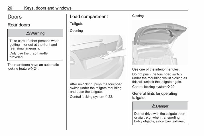
Opening
After unlocking, push the touchpadswitch under the tailgate mouldingand open the tailgate.Central locking system 3 22.
Closing
Use one of the interior handles.Do not push the touchpad switchunder the moulding whilst closing asthis will unlock the tailgate again.Central locking system 3 22.
General hints for operatingtailgate
9 Danger
Do not drive with the tailgate openor ajar, e.g. when transportingbulky objects, since toxic exhaust

Keys, doors and windows 27
gases, which cannot be seen orsmelled, could enter the vehicle.This can cause unconsciousnessand even death.
Caution
Before opening the tailgate checkoverhead obstructions, such as agarage door, to avoid damage tothe tailgate. Always check themoving area above and behind thetailgate.
NoticeThe installation of certain heavyaccessories onto the tailgate mayaffect its ability to remain open.
Vehicle securityAnti-theft locking system
9 Warning
Do not use the system if there arepeople in the vehicle! The doorscannot be unlocked from theinside.
The system deadlocks all the doors.All doors must be closed otherwisethe system cannot be activated.If the ignition was on, the driver's doormust be opened and closed once sothat the vehicle can be secured.Unlocking the vehicle disables themechanical anti-theft locking system.This is not possible with the centrallocking button.
Activating
Press e on the radio remote controltwice within 10 seconds.
Anti-theft alarm systemThe anti-theft alarm system isoperated in conjunction with thecentral locking system.It monitors:● doors, tailgate, bonnet● ignition
Unlocking the vehicle deactivates theanti-theft alarm system.
28 Keys, doors and windows
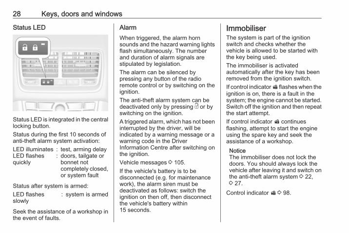
Status LED
Status LED is integrated in the centrallocking button.Status during the first 10 seconds ofanti-theft alarm system activation:LED illuminates : test, arming delayLED flashesquickly
: doors, tailgate orbonnet notcompletely closed,or system fault
Status after system is armed:LED flashesslowly
: system is armed
Seek the assistance of a workshop inthe event of faults.
AlarmWhen triggered, the alarm hornsounds and the hazard warning lightsflash simultaneously. The numberand duration of alarm signals arestipulated by legislation.The alarm can be silenced bypressing any button of the radioremote control or by switching on theignition.The anti-theft alarm system can bedeactivated only by pressing c or byswitching on the ignition.A triggered alarm, which has not beeninterrupted by the driver, will beindicated by a warning message or awarning code in the DriverInformation Centre after switching onthe ignition.Vehicle messages 3 105.If the vehicle's battery is to bedisconnected (e.g. for maintenancework), the alarm siren must bedeactivated as follows: switch theignition on then off, then disconnectthe vehicle's battery within15 seconds.
ImmobiliserThe system is part of the ignitionswitch and checks whether thevehicle is allowed to be started withthe key being used.The immobiliser is activatedautomatically after the key has beenremoved from the ignition switch.If control indicator d flashes when theignition is on, there is a fault in thesystem; the engine cannot be started.Switch off the ignition and then repeatthe start attempt.If control indicator d continuesflashing, attempt to start the engineusing the spare key and seek theassistance of a workshop.NoticeThe immobiliser does not lock thedoors. You should always lock thevehicle after leaving it and switch onthe anti-theft alarm system 3 22,3 27.
Control indicator d 3 98.
Keys, doors and windows 29
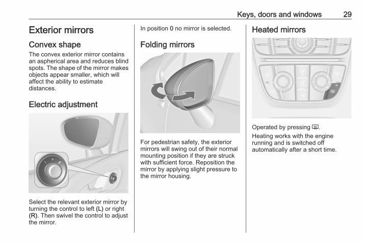
Exterior mirrorsConvex shapeThe convex exterior mirror containsan aspherical area and reduces blindspots. The shape of the mirror makesobjects appear smaller, which willaffect the ability to estimatedistances.
Electric adjustment
Select the relevant exterior mirror byturning the control to left (L) or right(R). Then swivel the control to adjustthe mirror.
In position 0 no mirror is selected.
Folding mirrors
For pedestrian safety, the exteriormirrors will swing out of their normalmounting position if they are struckwith sufficient force. Reposition themirror by applying slight pressure tothe mirror housing.
Heated mirrors
Operated by pressing Ü.Heating works with the enginerunning and is switched offautomatically after a short time.

30 Keys, doors and windows
Interior mirrorsManual anti-dazzle
To reduce dazzle, adjust the lever onthe underside of the mirror housing.
Automatic anti-dazzle
Dazzle from following vehicles atnight is automatically reduced.
WindowsWindscreenHeat-reflecting windscreenThe heat-reflecting windscreen has acoating which reflects solar radiation.Also data signals, e.g. from tollstations, might be reflected.
The marked areas on the windscreenare not covered with the coating.Devices for electronic data recordingand fee payment must be attached inthese areas. Otherwise datarecording malfunctions may occur.
Keys, doors and windows 31
Windscreen stickersDo not attach stickers such as tollroad stickers or similar on thewindscreen in the area of the interiormirror. Otherwise the detection zoneof the sensor and the view area of thecamera in the mirror housing could berestricted.
Manual windowsThe door windows can be opened orclosed with the window cranks.
Power windows
9 Warning
Take care when operating thepower windows. Risk of injury,particularly to children.If there are children on the rearseats, switch on the child safetysystem for the power windows.Keep a close watch on thewindows when closing them.Ensure that nothing becomestrapped in them as they move.
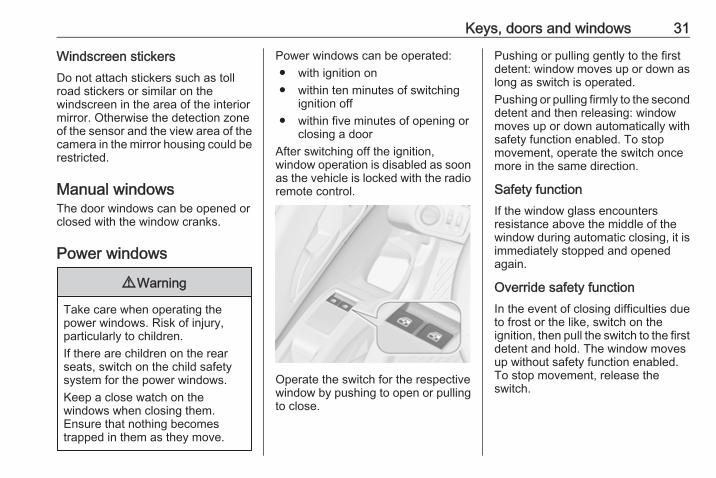
Power windows can be operated:● with ignition on● within ten minutes of switching
ignition off● within five minutes of opening or
closing a doorAfter switching off the ignition,window operation is disabled as soonas the vehicle is locked with the radioremote control.
Operate the switch for the respectivewindow by pushing to open or pullingto close.
Pushing or pulling gently to the firstdetent: window moves up or down aslong as switch is operated.Pushing or pulling firmly to the seconddetent and then releasing: windowmoves up or down automatically withsafety function enabled. To stopmovement, operate the switch oncemore in the same direction.
Safety functionIf the window glass encountersresistance above the middle of thewindow during automatic closing, it isimmediately stopped and openedagain.
Override safety functionIn the event of closing difficulties dueto frost or the like, switch on theignition, then pull the switch to the firstdetent and hold. The window movesup without safety function enabled.To stop movement, release theswitch.

32 Keys, doors and windows
Child safety system for rearwindows
Press z to deactivate rear doorpower windows, the LED illuminates.To activate, press z again.
Operating windows from outsideThe windows can be operatedremotely from outside the vehicle.
Press and hold c to open windows.Press and hold e to close windows.Release button to stop windowmovement.
OverloadIf the windows are repeatedlyoperated within short intervals, thewindow operation is disabled forsome time.
Initialising the power windowsIf the windows cannot be closedautomatically (e.g. afterdisconnecting the vehicle battery), a
warning message or a warning codeis displayed in the Driver InformationCentre.Vehicle messages 3 105.Activate the window electronics asfollows:1. Close doors.2. Switch on ignition.3. Pull switch until the window is
closed and keep pulling foradditional two seconds.
4. Repeat for each window.
Heated rear window
Operated by pressing Ü.

Keys, doors and windows 33
Heating works with the enginerunning and is switched offautomatically after a short time.Depending on the engine type, theheated rear window comes onautomatically when the diesel particlefilter is being cleaned.
Sun visorsThe sun visors can be folded down orswivelled to the side to preventdazzling.If the sun visors have integral mirrors,the mirror covers should be closedwhen driving.A ticket holder is located on the backof the sun visor.
RoofMoonroofDo not affix any stickers to the roof.Do not cover the vehicle using atarpaulin.
SunblindThe sunblind is electrically operated.
Press G or H gently to the firstdetent: the sunblind is opened orclosed as long as the switch isoperated.
Press G or H firmly to the seconddetent and then release: the sunblindis opened or closed automatically. Tostop movement, operate the switchonce more.
Safety functionIf the sunblind encounters resistanceduring automatic closing, it isimmediately stopped and openedagain.
Function standbyIn ignition switch position 1 thesunblind is operable 3 139.
Initialising after a power failureAfter a power failure, it may only bepossible to operate the sunblind to alimited extent. Have the systeminitialised by your workshop.

34 Seats, restraints
Seats, restraints
Head restraints ............................ 34Active head restraints ................ 35
Front seats ................................... 36Seat position .............................. 36Seat adjustment ........................ 37Armrest ...................................... 39Heating ...................................... 40
Rear seats ................................... 41Armrest ...................................... 42
Seat belts ..................................... 44Three-point seat belt ................. 45
Airbag system .............................. 48Front airbag system ................... 51Side airbag system .................... 51Curtain airbag system ............... 52Airbag deactivation .................... 52
Child restraints ............................. 54Child restraint systems .............. 54Child restraint installationlocations ................................... 56
ISOFIX child restraint systems . . 59Top-tether fastening eyes .......... 59
Head restraints
Position
9 Warning
Only drive with the head restraintset to the proper position.
The upper edge of the head restraintshould be at upper head level. If thisis not possible for extremely tallpeople, set to highest position, andset to lowest position for small people.
Adjustment
Head restraints on front seats
Height adjustmentPress release button, adjust heightand engage.
Seats, restraints 35
Horizontal adjustment
To adjust horizontally, pull the headrestraint forwards. It engages inseveral positions.To return to its rearmost position, pullfully forwards and release.
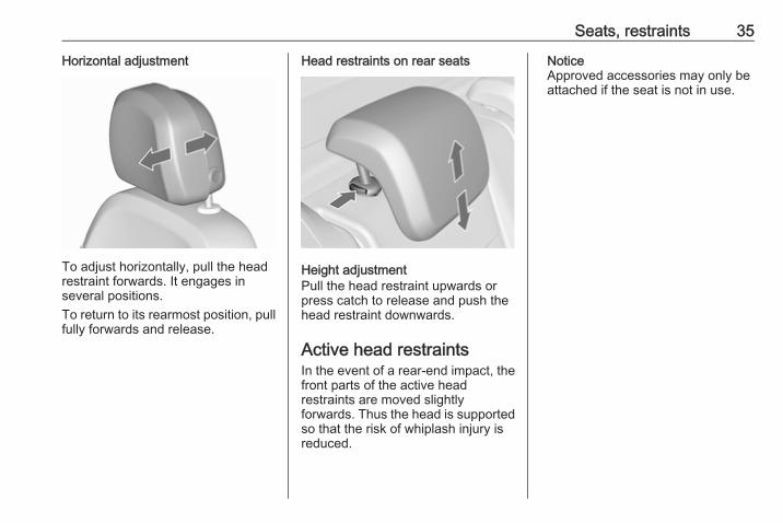
Head restraints on rear seats
Height adjustmentPull the head restraint upwards orpress catch to release and push thehead restraint downwards.
Active head restraintsIn the event of a rear-end impact, thefront parts of the active headrestraints are moved slightlyforwards. Thus the head is supportedso that the risk of whiplash injury isreduced.
NoticeApproved accessories may only beattached if the seat is not in use.
36 Seats, restraints
Front seatsSeat position
9 Warning
Only drive with the seat correctlyadjusted.
9 Danger
Do not sit nearer than 25 cm fromthe steering wheel, to permit safeairbag deployment.
9 Warning
Never adjust seats while driving asthey could move uncontrollably.
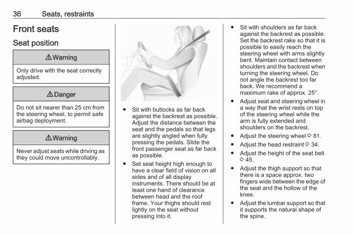
● Sit with buttocks as far backagainst the backrest as possible.Adjust the distance between theseat and the pedals so that legsare slightly angled when fullypressing the pedals. Slide thefront passenger seat as far backas possible.
● Set seat height high enough tohave a clear field of vision on allsides and of all displayinstruments. There should be atleast one hand of clearancebetween head and the roofframe. Your thighs should restlightly on the seat withoutpressing into it.
● Sit with shoulders as far backagainst the backrest as possible.Set the backrest rake so that it ispossible to easily reach thesteering wheel with arms slightlybent. Maintain contact betweenshoulders and the backrest whenturning the steering wheel. Donot angle the backrest too farback. We recommend amaximum rake of approx. 25°.
● Adjust seat and steering wheel ina way that the wrist rests on topof the steering wheel while thearm is fully extended andshoulders on the backrest.
● Adjust the steering wheel 3 81.● Adjust the head restraint 3 34.● Adjust the height of the seat belt
3 45.● Adjust the thigh support so that
there is a space approx. twofingers wide between the edge ofthe seat and the hollow of theknee.
● Adjust the lumbar support so thatit supports the natural shape ofthe spine.
Seats, restraints 37
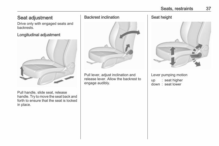
Seat adjustmentDrive only with engaged seats andbackrests.
Longitudinal adjustment
Pull handle, slide seat, releasehandle. Try to move the seat back andforth to ensure that the seat is lockedin place.
Backrest inclination
Pull lever, adjust inclination andrelease lever. Allow the backrest toengage audibly.
Seat height
Lever pumping motionup : seat higherdown : seat lower
38 Seats, restraints
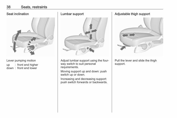
Seat inclination
Lever pumping motionup : front end higherdown : front end lower
Lumbar support
Adjust lumbar support using the four-way switch to suit personalrequirements.Moving support up and down: pushswitch up or down.Increasing and decreasing support:push switch forwards or backwards.
Adjustable thigh support
Pull the lever and slide the thighsupport.

Seats, restraints 39
ArmrestDetachable armrest
The armrest contains a storagecompartment.Storage compartment 3 62.
Installing armrest on the centreconsole
Press the rear button and insert therear guide pins into the upper guiderails. Release the button.
Lower the armrest at the front. Pull thefront handle firmly and insert the frontguide pins into the upper guide rails.Release the handle. Move thearmrest until it engages audibly.NoticeInstall the armrest in the directionshown in the illustration. Otherwisethe armrest may not engageproperly.
40 Seats, restraints
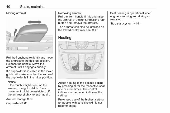
Moving armrest
Pull the front handle slightly and movethe armrest to the desired position.Release the handle. Move thearmrest until it engages audibly.If a cupholder is installed in the lowerguide rail, make sure that the frame ofthe cupholder is in the initial position.NoticeIf too much weight is put on thearmrest, it might unlatch. Ease ofmovement might be restricted. Liftthe armrest slightly to latch again.
Armrest storage 3 62.Cupholders 3 60.
Removing armrestPull the front handle firmly and raisethe armrest at the front. Press the rearbutton and remove the armrest.The armrest can also be installed onthe folded centre rear seat 3 42.
Heating
Adjust heating to the desired settingby pressing ß for the respective seatone or more times. The controlindicator in the button indicates thesetting.Prolonged use of the highest settingfor people with sensitive skin is notrecommended.
Seat heating is operational whenengine is running and during anAutostop.Stop-start system 3 141.
Seats, restraints 41
Rear seats
Seat adjustment
9 Warning
Only drive with the outer seatsengaged in the guide rails.
9 Warning
Never adjust seats while driving asthey could move uncontrollably.
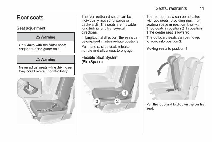
The rear outboard seats can beindividually moved forwards orbackwards. The seats are movable inlongitudinal and transversaldirections.In longitudinal direction, the seats canbe engaged in intermediate positions.Pull handle, slide seat, releasehandle and allow seat to engage.
Flexible Seat System(FlexSpace)
The rear seat row can be adjustedwith two seats, providing maximumseating space in position 1, or withthree seats in position 2. In position1 the centre seat is lowered.The outboard seats can be movedforward into position 3.
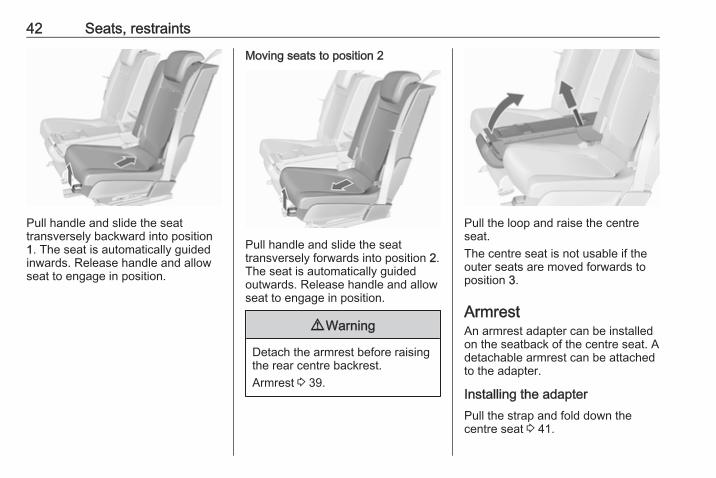
Moving seats to position 1
Pull the loop and fold down the centreseat.
42 Seats, restraints
Pull handle and slide the seattransversely backward into position1. The seat is automatically guidedinwards. Release handle and allowseat to engage in position.
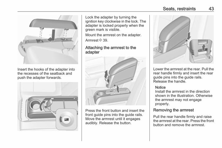
Moving seats to position 2
Pull handle and slide the seattransversely forwards into position 2.The seat is automatically guidedoutwards. Release handle and allowseat to engage in position.
9 Warning
Detach the armrest before raisingthe rear centre backrest.Armrest 3 39.
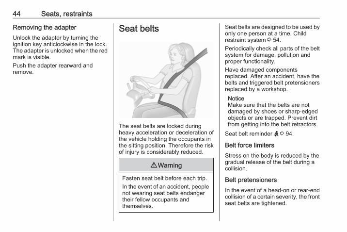
Pull the loop and raise the centreseat.The centre seat is not usable if theouter seats are moved forwards toposition 3.
ArmrestAn armrest adapter can be installedon the seatback of the centre seat. Adetachable armrest can be attachedto the adapter.
Installing the adapterPull the strap and fold down thecentre seat 3 41.
Seats, restraints 43
Insert the hooks of the adapter intothe recesses of the seatback andpush the adapter forwards.
Lock the adapter by turning theignition key clockwise in the lock. Theadapter is locked properly when thegreen mark is visible.Mount the armrest on the adapter.Armrest 3 39.
Attaching the armrest to theadapter
Press the front button and insert thefront guide pins into the guide rails.Move the armrest until it engagesaudibly. Release the button.
Lower the armrest at the rear. Pull therear handle firmly and insert the rearguide pins into the guide rails.Release the handle.NoticeInstall the armrest in the directionshown in the illustration. Otherwisethe armrest may not engageproperly.
Removing the armrestPull the rear handle firmly and raisethe armrest at the rear. Press the frontbutton and remove the armrest.
44 Seats, restraints
Removing the adapterUnlock the adapter by turning theignition key anticlockwise in the lock.The adapter is unlocked when the redmark is visible.Push the adapter rearward andremove.
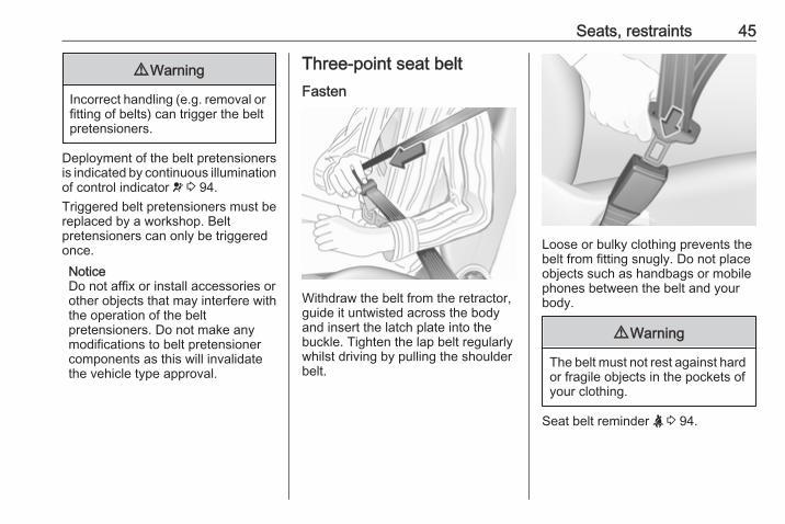
Seat belts
The seat belts are locked duringheavy acceleration or deceleration ofthe vehicle holding the occupants inthe sitting position. Therefore the riskof injury is considerably reduced.
9 Warning
Fasten seat belt before each trip.In the event of an accident, peoplenot wearing seat belts endangertheir fellow occupants andthemselves.
Seat belts are designed to be used byonly one person at a time. Childrestraint system 3 54.Periodically check all parts of the beltsystem for damage, pollution andproper functionality.Have damaged componentsreplaced. After an accident, have thebelts and triggered belt pretensionersreplaced by a workshop.NoticeMake sure that the belts are notdamaged by shoes or sharp-edgedobjects or are trapped. Prevent dirtfrom getting into the belt retractors.
Seat belt reminder X 3 94.
Belt force limitersStress on the body is reduced by thegradual release of the belt during acollision.
Belt pretensionersIn the event of a head-on or rear-endcollision of a certain severity, the frontseat belts are tightened.
Seats, restraints 45
9 Warning
Incorrect handling (e.g. removal orfitting of belts) can trigger the beltpretensioners.
Deployment of the belt pretensionersis indicated by continuous illuminationof control indicator v 3 94.Triggered belt pretensioners must bereplaced by a workshop. Beltpretensioners can only be triggeredonce.NoticeDo not affix or install accessories orother objects that may interfere withthe operation of the beltpretensioners. Do not make anymodifications to belt pretensionercomponents as this will invalidatethe vehicle type approval.
Three-point seat beltFasten
Withdraw the belt from the retractor,guide it untwisted across the bodyand insert the latch plate into thebuckle. Tighten the lap belt regularlywhilst driving by pulling the shoulderbelt.
Loose or bulky clothing prevents thebelt from fitting snugly. Do not placeobjects such as handbags or mobilephones between the belt and yourbody.
9 Warning
The belt must not rest against hardor fragile objects in the pockets ofyour clothing.
Seat belt reminder X 3 94.
46 Seats, restraints
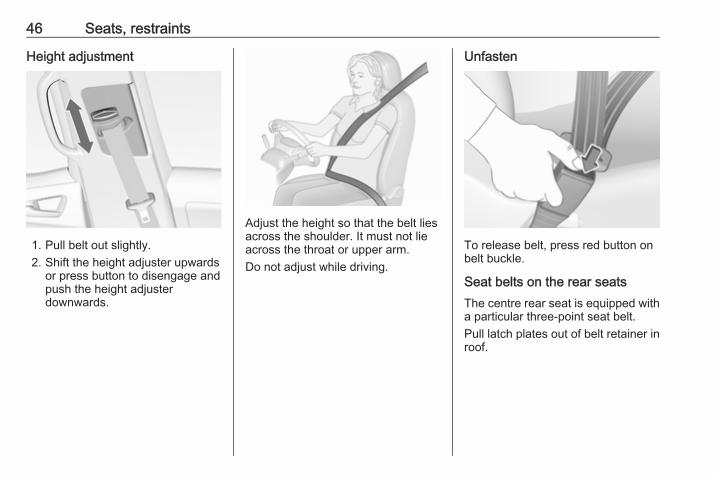
Height adjustment
1. Pull belt out slightly.2. Shift the height adjuster upwards
or press button to disengage andpush the height adjusterdownwards.
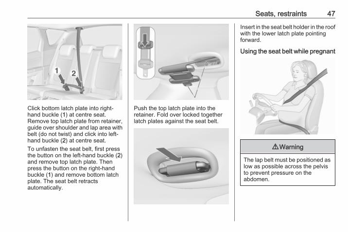
Adjust the height so that the belt liesacross the shoulder. It must not lieacross the throat or upper arm.Do not adjust while driving.
Unfasten
To release belt, press red button onbelt buckle.
Seat belts on the rear seatsThe centre rear seat is equipped witha particular three-point seat belt.Pull latch plates out of belt retainer inroof.
Seats, restraints 47
Click bottom latch plate into right-hand buckle (1) at centre seat.Remove top latch plate from retainer,guide over shoulder and lap area withbelt (do not twist) and click into left-hand buckle (2) at centre seat.To unfasten the seat belt, first pressthe button on the left-hand buckle (2)and remove top latch plate. Thenpress the button on the right-handbuckle (1) and remove bottom latchplate. The seat belt retractsautomatically.
Push the top latch plate into theretainer. Fold over locked togetherlatch plates against the seat belt.
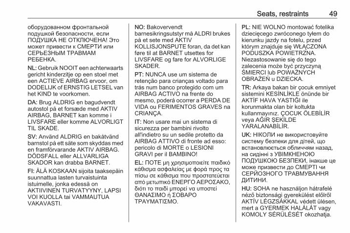
Insert in the seat belt holder in the roofwith the lower latch plate pointingforward.
Using the seat belt while pregnant
9 Warning
The lap belt must be positioned aslow as possible across the pelvisto prevent pressure on theabdomen.
48 Seats, restraints
Airbag systemThe airbag system consists of anumber of individual systemsdepending on the scope ofequipment.When triggered the airbags inflatewithin milliseconds. They also deflateso quickly that it is often unnoticeableduring the collision.
9 Warning
If handled improperly the airbagsystems can be triggered in anexplosive manner.
NoticeThe airbag systems and beltpretensioner control electronics arelocated in the centre console area.Do not put any magnetic objects inthis area.Do not stick anything on the airbagcovers and do not cover them withother materials.Each airbag is triggered only once.Have deployed airbags replaced bya workshop. Furthermore, it might be
necessary to have the steeringwheel, the instrument panel, parts ofthe panelling, the door seals,handles and the seats replaced.Do not make any modifications tothe airbag system as this willinvalidate the vehicle type approval.
When the airbags inflate, escapinghot gases may cause burns.Control indicator v for airbag systems3 94.
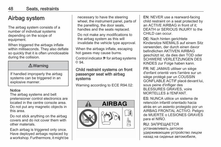
Child restraint systems on frontpassenger seat with airbagsystemsWarning according to ECE R94.02:
EN: NEVER use a rearward-facingchild restraint on a seat protected byan ACTIVE AIRBAG in front of it;DEATH or SERIOUS INJURY to theCHILD can occur.DE: Nach hinten gerichteteKindersitze NIEMALS auf einem Sitzverwenden, der durch einen davorbefindlichen AKTIVEN AIRBAGgeschützt ist, da dies den TOD oderSCHWERE VERLETZUNGEN DESKINDES zur Folge haben kann.FR: NE JAMAIS utiliser un sièged'enfant orienté vers l'arrière sur unsiège protégé par un COUSSINGONFLABLE ACTIF placé devant lui,sous peine d'infliger desBLESSURES GRAVES, voireMORTELLES à l'ENFANT.ES: NUNCA utilice un sistema deretención infantil orientado haciaatrás en un asiento protegido por unAIRBAG FRONTAL ACTIVO. Peligrode MUERTE o LESIONES GRAVESpara el NIÑO.RU: ЗАПРЕЩАЕТСЯустанавливать детскоеудерживающее устройство лицомназад на сиденье автомобиля,
Seats, restraints 49
оборудованном фронтальнойподушкой безопасности, еслиПОДУШКА НЕ ОТКЛЮЧЕНА! Этоможет привести к СМЕРТИ илиСЕРЬЕЗНЫМ ТРАВМАМРЕБЕНКА.NL: Gebruik NOOIT een achterwaartsgericht kinderzitje op een stoel meteen ACTIEVE AIRBAG ervoor, omDODELIJK of ERNSTIG LETSEL vanhet KIND te voorkomen.DA: Brug ALDRIG en bagudvendtautostol på et forsæde med AKTIVAIRBAG, BARNET kan komme iLIVSFARE eller komme ALVORLIGTTIL SKADE.SV: Använd ALDRIG en bakåtvändbarnstol på ett säte som skyddas meden framförvarande AKTIV AIRBAG.DÖDSFALL eller ALLVARLIGASKADOR kan drabba BARNET.FI: ÄLÄ KOSKAAN sijoita taaksepäinsuunnattua lasten turvaistuintaistuimelle, jonka edessä onAKTIIVINEN TURVATYYNY, LAPSIVOI KUOLLA tai VAMMAUTUAVAKAVASTI.
NO: Bakovervendtbarnesikringsutstyr må ALDRI brukespå et sete med AKTIVKOLLISJONSPUTE foran, da det kanføre til at BARNET utsettes forLIVSFARE og fare for ALVORLIGESKADER.PT: NUNCA use um sistema deretenção para crianças voltado paratrás num banco protegido com umAIRBAG ACTIVO na frente domesmo, poderá ocorrer a PERDA DEVIDA ou FERIMENTOS GRAVES naCRIANÇA.IT: Non usare mai un sistema disicurezza per bambini rivoltoall'indietro su un sedile protetto daAIRBAG ATTIVO di fronte ad esso:pericolo di MORTE o LESIONIGRAVI per il BAMBINO!EL: ΠΟΤΕ μη χρησιμοποιείτε παιδικόκάθισμα ασφαλείας με φορά προς ταπίσω σε κάθισμα που προστατεύεταιαπό μετωπικό ΕΝΕΡΓΟ ΑΕΡΟΣΑΚΟ,διότι το παιδί μπορεί να υποστείΘΑΝΑΣΙΜΟ ή ΣΟΒΑΡΟΤΡΑΥΜΑΤΙΣΜΟ.
PL: NIE WOLNO montować fotelikadziecięcego zwróconego tyłem dokierunku jazdy na fotelu, przedktórym znajduje się WŁĄCZONAPODUSZKA POWIETRZNA.Niezastosowanie się do tegozalecenia może być przyczynąŚMIERCI lub POWAŻNYCHOBRAŻEŃ u DZIECKA.TR: Arkaya bakan bir çocuk emniyetsistemini KESİNLİKLE önünde birAKTİF HAVA YASTIĞI ilekorunmakta olan bir koltuktakullanmayınız. ÇOCUK ÖLEBİLİRveya AĞIR ŞEKİLDEYARALANABİLİR.UK: НІКОЛИ не використовуйтесистему безпеки для дітей, щовстановлюється обличчям назад,на сидінні з УВІМКНЕНОЮПОДУШКОЮ БЕЗПЕКИ, інакше цеможе призвести до СМЕРТІ чиСЕРЙОЗНОГО ТРАВМУВАННЯДИТИНИ.HU: SOHA ne használjon hátrafelénéző biztonsági gyerekülést előlrőlAKTÍV LÉGZSÁKKAL védett ülésen,mert a GYERMEK HALÁLÁT vagyKOMOLY SÉRÜLÉSÉT okozhatja.
50 Seats, restraints
HR: NIKADA nemojte koristiti sustavzadržavanja za djecu okrenut premanatrag na sjedalu s AKTIVNIMZRAČNIM JASTUKOM ispred njega,to bi moglo dovesti do SMRTI iliOZBILJNJIH OZLJEDA za DIJETE.SL: NIKOLI ne nameščajte otroškegavarnostnega sedeža, obrnjenega vnasprotni smeri vožnje, na sedež zAKTIVNO ČELNO ZRAČNOBLAZINO, saj pri tem obstajanevarnost RESNIH ali SMRTNIHPOŠKODB za OTROKA.SR: NIKADA ne koristiti bezbednosnisistem za decu u kome su decaokrenuta unazad na sedištu saAKTIVNIM VAZDUŠNIMJASTUKOM ispred sedišta zato štoDETE može da NASTRADA ili da seTEŠKO POVREDI.MK: НИКОГАШ не користете детскоседиште свртено наназад наседиште заштитено со АКТИВНОВОЗДУШНО ПЕРНИЧЕ пред него,затоа што детето може ДА ЗАГИНЕили да биде ТЕШКО ПОВРЕДЕНО.BG: НИКОГА не използвайтедетска седалка, гледаща назад,върху седалка, която е защитена
чрез АКТИВНА ВЪЗДУШНАВЪЗГЛАВНИЦА пред нея - може дасе стигне до СМЪРТ илиСЕРИОЗНО НАРАНЯВАНЕ наДЕТЕТО.RO: Nu utilizaţi NICIODATĂ un scaunpentru copil îndreptat spre partea dinspate a maşinii pe un scaun protejatde un AIRBAG ACTIV în faţa sa;acest lucru poate duce la DECESULsau VĂTĂMAREA GRAVĂ aCOPILULUI.CS: NIKDY nepoužívejte dětskýzádržný systém instalovaný protisměru jízdy na sedadle, které jechráněno před sedadlem AKTIVNÍMAIRBAGEM. Mohlo by dojít kVÁŽNÉMU PORANĚNÍ nebo ÚMRTÍDÍTĚTE.SK: NIKDY nepoužívajte detskúsedačku otočenú vzad na sedadlechránenom AKTÍVNYM AIRBAGOM,pretože môže dôjsť k SMRTI aleboVÁŽNYM ZRANENIAM DIEŤAŤA.LT: JOKIU BŪDU nemontuokite atgalatgręžtos vaiko tvirtinimo sistemossėdynėje, prieš kurią įrengta AKTYVIORO PAGALVĖ, nes VAIKAS GALIŽŪTI arba RIMTAI SUSIŽALOTI.
LV: NEKĀDĀ GADĪJUMĀneizmantojiet uz aizmuguri vērstubērnu sēdeklīti sēdvietā, kas tiekaizsargāta ar tās priekšā uzstādītuAKTĪVU DROŠĪBAS SPILVENU, jopretējā gadījumā BĒRNS var gūtSMAGAS TRAUMAS vai IET BOJĀ.ET: ÄRGE kasutage tahapoolesuunatud lapseturvaistet istmel, milleees on AKTIIVSE TURVAPADJAGAkaitstud iste, sest see võibpõhjustada LAPSE SURMA võiTÕSISE VIGASTUSE.MT: QATT tuża trażżin għat-tfal lijħares lejn in-naħa ta’ wara fuq sitprotett b’AIRBAG ATTIV quddiemu;dan jista’ jikkawża l-MEWT jewĠRIEĦI SERJI lit-TFAL.Beyond the warning required byECE R94.02, for safety reasonsnever use a forward-facing childrestraint system on the passengerseat with an active front airbag.
9 Danger
Do not use a child restraint systemon the passenger seat with activefront airbag.

Seats, restraints 51
The airbag label is located on bothsides of the front passenger sun visor.Airbag deactivation 3 52.
Front airbag systemThe front airbag system consists ofone airbag in the steering wheel andone in the instrument panel on thefront passenger side. These can beidentified by the word AIRBAG.The front airbag system is triggered inthe event of a front-end impact of acertain severity. The ignition must beswitched on.
The inflated airbags cushion theimpact, thereby reducing the risk ofinjury to the upper body and head ofthe front seat occupantsconsiderably.
9 Warning
Optimum protection is onlyprovided when the seat is in theproper position.Seat position 3 36.Keep the area in which the airbaginflates clear of obstructions.Fit the seat belt correctly andengage securely. Only then is theairbag able to protect.
Side airbag system
The side airbag system consists of anairbag in each front seat backrest.This can be identified by the wordAIRBAG.The side airbag system is triggered inthe event of a side impact of a certainseverity. The ignition must beswitched on.
52 Seats, restraints
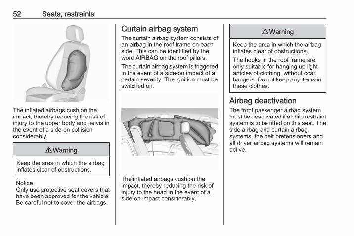
The inflated airbags cushion theimpact, thereby reducing the risk ofinjury to the upper body and pelvis inthe event of a side-on collisionconsiderably.
9 Warning
Keep the area in which the airbaginflates clear of obstructions.
NoticeOnly use protective seat covers thathave been approved for the vehicle.Be careful not to cover the airbags.
Curtain airbag systemThe curtain airbag system consists ofan airbag in the roof frame on eachside. This can be identified by theword AIRBAG on the roof pillars.The curtain airbag system is triggeredin the event of a side-on impact of acertain severity. The ignition must beswitched on.
The inflated airbags cushion theimpact, thereby reducing the risk ofinjury to the head in the event of aside-on impact considerably.
9 Warning
Keep the area in which the airbaginflates clear of obstructions.The hooks in the roof frame areonly suitable for hanging up lightarticles of clothing, without coathangers. Do not keep any items inthese clothes.
Airbag deactivationThe front passenger airbag systemmust be deactivated if a child restraintsystem is to be fitted on this seat. Theside airbag and curtain airbagsystems, the belt pretensioners andall driver airbag systems will remainactive.
Seats, restraints 53
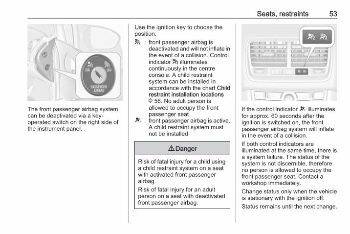
The front passenger airbag systemcan be deactivated via a key-operated switch on the right side ofthe instrument panel.
Use the ignition key to choose theposition:* : front passenger airbag is
deactivated and will not inflate inthe event of a collision. Controlindicator * illuminatescontinuously in the centreconsole. A child restraintsystem can be installed inaccordance with the chart Childrestraint installation locations3 56. No adult person isallowed to occupy the frontpassenger seat
V : front passenger airbag is active.A child restraint system mustnot be installed
9 Danger
Risk of fatal injury for a child usinga child restraint system on a seatwith activated front passengerairbag.Risk of fatal injury for an adultperson on a seat with deactivatedfront passenger airbag.
If the control indicator V illuminatesfor approx. 60 seconds after theignition is switched on, the frontpassenger airbag system will inflatein the event of a collision.If both control indicators areilluminated at the same time, there isa system failure. The status of thesystem is not discernible, thereforeno person is allowed to occupy thefront passenger seat. Contact aworkshop immediately.Change status only when the vehicleis stationary with the ignition off.Status remains until the next change.
54 Seats, restraints
Control indicator for airbagdeactivation 3 94. Child restraints
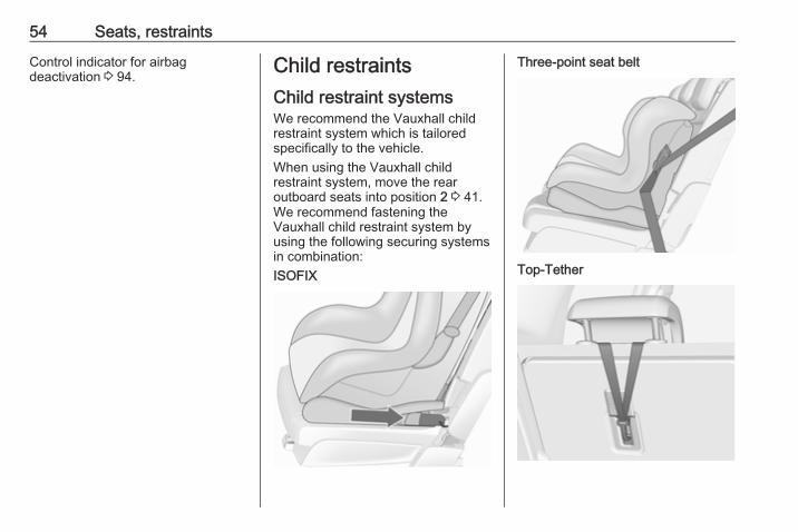
Child restraint systemsWe recommend the Vauxhall childrestraint system which is tailoredspecifically to the vehicle.When using the Vauxhall childrestraint system, move the rearoutboard seats into position 2 3 41.We recommend fastening theVauxhall child restraint system byusing the following securing systemsin combination:ISOFIX
Three-point seat belt
Top-Tether

Seats, restraints 55
When a child restraint system is beingused, pay attention to the followingusage and installation instructionsand also those supplied with the childrestraint system.Always comply with local or nationalregulations. In some countries, theuse of child restraint systems isforbidden on certain seats.
9 Warning
If using a child restraint system onthe front passenger seat, theairbag system for the frontpassenger seat must bedeactivated; if not, the triggering ofthe front airbag poses a risk of fatalinjury to the child.This is especially the case ifrearfacing child restraint systemsare used on the front passengerseat.
Airbag deactivation 3 52,Airbag label 3 48.
Selecting the right systemThe rear seats are the mostconvenient location to fasten a childrestraint system.Children should travel facingrearwards in the vehicle as long aspossible. This makes sure that thechild's backbone, which is still veryweak, is under less strain in the eventof an accident.Suitable are restraint systems thatcomply with valid UN ECEregulations. Check local laws andregulations for mandatory use of childrestraint systems.Ensure that the child restraint systemto be installed is compatible with thevehicle type.Ensure that the mounting location ofthe child restraint system within thevehicle is correct, see followingtables.Allow children to enter and exit thevehicle only on the side facing awayfrom the traffic.When the child restraint system is notin use, secure the seat with a seat beltor remove it from the vehicle.
NoticeDo not stick anything on the childrestraint systems and do not coverthem with any other materials.A child restraint system which hasbeen subjected to stress in anaccident must be replaced.

56 Seats, restraints
Child restraint installation locationsPermissible options for fitting a child restraint system
Weight and age classOn front passenger seat
On rear outboard seats On rear centre seatactivated airbag deactivated airbag
Group 0: up to 10 kgor approx. 10 months
X U1 U2 U3
Group 0+: up to 13 kgor approx. 2 years
X U1 U2 U3
Group I: 9 to 18 kgor approx. 8 months to 4 years
X U1 U2 U3
Group II: 15 to 25 kgor approx. 3 to 7 years
X X U2 U3
Group III: 22 to 36 kgor approx. 6 to 12 years
X X U2 U3
1 : if the child restraint system is being secured using a three-point seat belt, move seat height adjustment to uppermostposition and ensure that vehicle seat belt runs forwards from the upper anchorage point. Adjust seat backrestinclination as far as necessary to a vertical position to ensure that the belt is tight on the buckle side.
2 : only if outboard seats are in position 1 or 2, 3 41.3 : only if outboard seats are flush with the centre seat (position 2, 3 41).U : universal suitability in conjunction with three-point seat belt.X : no child restraint system permitted in this weight and age class.
Seats, restraints 57
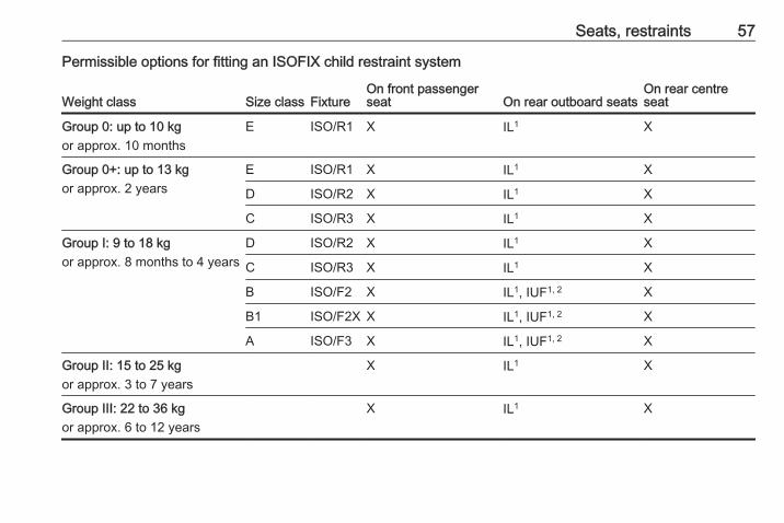
Permissible options for fitting an ISOFIX child restraint system
Weight class Size class FixtureOn front passengerseat On rear outboard seats
On rear centreseat
Group 0: up to 10 kgor approx. 10 months
E ISO/R1 X IL1 X
Group 0+: up to 13 kgor approx. 2 years
E ISO/R1 X IL1 X
D ISO/R2 X IL1 X
C ISO/R3 X IL1 X
Group I: 9 to 18 kgor approx. 8 months to 4 years
D ISO/R2 X IL1 X
C ISO/R3 X IL1 X
B ISO/F2 X IL1, IUF1, 2 X
B1 ISO/F2X X IL1, IUF1, 2 X
A ISO/F3 X IL1, IUF1, 2 X
Group II: 15 to 25 kgor approx. 3 to 7 years
X IL1 X
Group III: 22 to 36 kgor approx. 6 to 12 years
X IL1 X
58 Seats, restraints
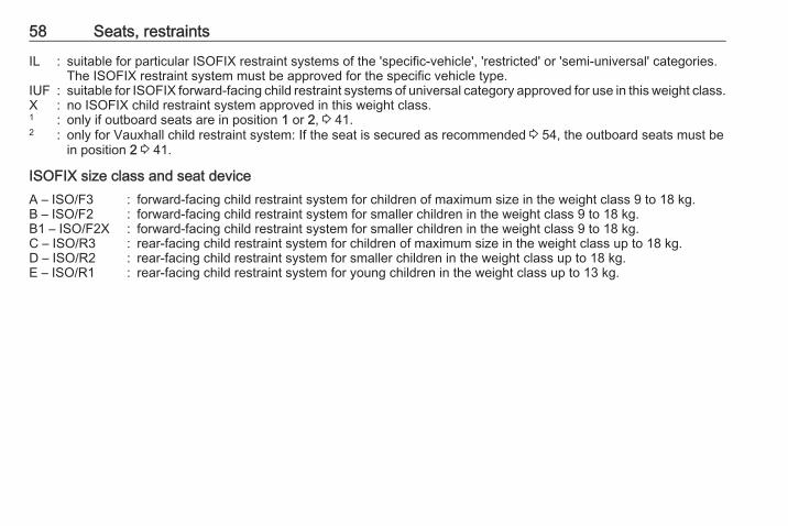
IL : suitable for particular ISOFIX restraint systems of the 'specific-vehicle', 'restricted' or 'semi-universal' categories.The ISOFIX restraint system must be approved for the specific vehicle type.
IUF : suitable for ISOFIX forward-facing child restraint systems of universal category approved for use in this weight class.X : no ISOFIX child restraint system approved in this weight class.1 : only if outboard seats are in position 1 or 2, 3 41.2 : only for Vauxhall child restraint system: If the seat is secured as recommended 3 54, the outboard seats must be
in position 2 3 41.
ISOFIX size class and seat deviceA – ISO/F3 : forward-facing child restraint system for children of maximum size in the weight class 9 to 18 kg.B – ISO/F2 : forward-facing child restraint system for smaller children in the weight class 9 to 18 kg.B1 – ISO/F2X : forward-facing child restraint system for smaller children in the weight class 9 to 18 kg.C – ISO/R3 : rear-facing child restraint system for children of maximum size in the weight class up to 18 kg.D – ISO/R2 : rear-facing child restraint system for smaller children in the weight class up to 18 kg.E – ISO/R1 : rear-facing child restraint system for young children in the weight class up to 13 kg.

Seats, restraints 59
ISOFIX child restraintsystems
Fasten vehicle-approved ISOFIXchild restraint systems to the ISOFIXmounting brackets. Specific vehicleISOFIX child restraint systempositions are marked in the table byIL.ISOFIX mounting brackets areindicated by a label on the backrest.
Top-tether fastening eyesTop-Tether fastening eyes aremarked with the symbol : for a childseat.
In addition to the ISOFIX mounting,fasten the Top-Tether strap to theTop-Tether fastening eyes. The strapmust run between the two guide rodsof the head restraint.ISOFIX child restraint systems ofuniversal category positions aremarked in the table by IUF.
60 Storage
Storage
Storage compartments ................ 60Glovebox ................................... 60Cupholders ................................ 60Front storage ............................. 62Underseat storage ..................... 62Armrest storage ......................... 62Rear carrier system ................... 63
Load compartment ....................... 72Rear storage .............................. 73Load compartment cover ........... 73Rear floor storage cover ............ 74Lashing eyes ............................. 75Safety net .................................. 75Folding tray ................................ 77Warning triangle ........................ 77First aid kit ................................. 77
Roof rack system ......................... 78Roof rack ................................... 78
Loading information ..................... 78
Storage compartments
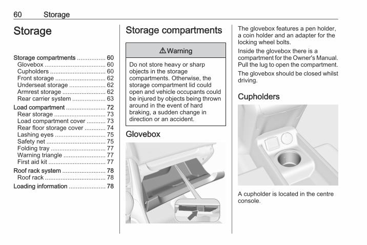
9 Warning
Do not store heavy or sharpobjects in the storagecompartments. Otherwise, thestorage compartment lid couldopen and vehicle occupants couldbe injured by objects being thrownaround in the event of hardbraking, a sudden change indirection or an accident.
Glovebox
The glovebox features a pen holder,a coin holder and an adapter for thelocking wheel bolts.Inside the glovebox there is acompartment for the Owner's Manual.Pull the lug to open the compartment.The glovebox should be closed whilstdriving.
Cupholders
A cupholder is located in the centreconsole.
Storage 61
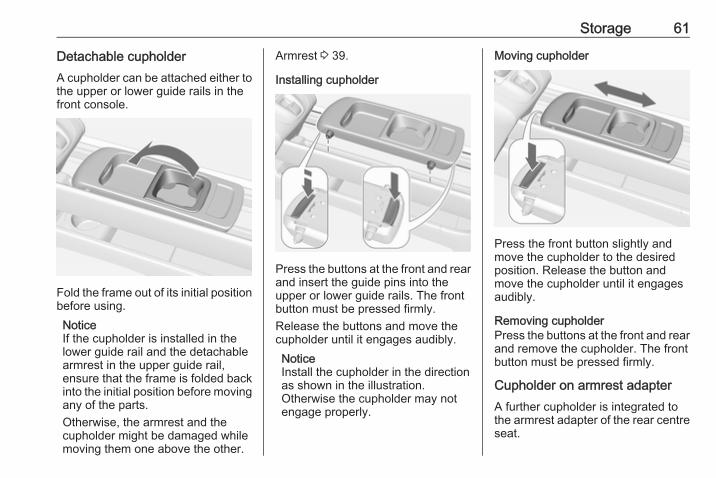
Detachable cupholderA cupholder can be attached either tothe upper or lower guide rails in thefront console.
Fold the frame out of its initial positionbefore using.NoticeIf the cupholder is installed in thelower guide rail and the detachablearmrest in the upper guide rail,ensure that the frame is folded backinto the initial position before movingany of the parts.Otherwise, the armrest and thecupholder might be damaged whilemoving them one above the other.
Armrest 3 39.
Installing cupholder
Press the buttons at the front and rearand insert the guide pins into theupper or lower guide rails. The frontbutton must be pressed firmly.Release the buttons and move thecupholder until it engages audibly.NoticeInstall the cupholder in the directionas shown in the illustration.Otherwise the cupholder may notengage properly.
Moving cupholder
Press the front button slightly andmove the cupholder to the desiredposition. Release the button andmove the cupholder until it engagesaudibly.
Removing cupholderPress the buttons at the front and rearand remove the cupholder. The frontbutton must be pressed firmly.
Cupholder on armrest adapterA further cupholder is integrated tothe armrest adapter of the rear centreseat.

62 Storage
Armrest adapter 3 42.
Front storage
A storage compartment is locatednext to the steering wheel.
Underseat storage
Lift drawer at recessed edge and pullout. Maximum load: 3 kg. To close,push the drawer in and engage.
Armrest storageStorage in the detachable armrest
Push button and fold the armrest lidupwards. The armrest contains astorage compartment.The armrest can also be installed onthe folded centre rear seat 3 42.
Storage 63
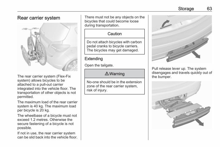
Rear carrier system
The rear carrier system (Flex-Fixsystem) allows bicycles to beattached to a pull-out carrierintegrated into the vehicle floor. Thetransportation of other objects is notpermitted.The maximum load of the rear carriersystem is 40 kg. The maximum loadper bicycle is 20 kg.The wheelbase of a bicycle must notexceed 1.2 metres. Otherwise thesecure fastening of a bicycle is notpossible.If not in use, the rear carrier systemcan be slid back into the vehicle floor.
There must not be any objects on thebicycles that could become looseduring transportation.
Caution
Do not attach bicycles with carbonpedal cranks to bicycle carriers.The bicycles may get damaged.
ExtendingOpen the tailgate.
9 Warning
No-one should be in the extensionzone of the rear carrier system,risk of injury.
Pull release lever up. The systemdisengages and travels quickly out ofthe bumper.

64 Storage
Completely pull out the rear carriersystem until you hear it engage.Ensure that it is not possible to pushin the rear carrier system withoutpulling the release lever again
9 Warning
It is only permissible to fit objectsto the rear carrier system if thesystem has been correctlyengaged. If the rear carrier systemwill not engage correctly, do not fitobjects to the system and slide thesystem back. Seek the assistanceof a workshop.
Install the tail lamps
First remove the rear tail lamp (1),then the front (2) tail lamp from therecesses.
Open out the lamp support on theback of the tail lamp completely.
Push the clamping lever down andpush the lamp support into theretainer until it engages.Perform this procedure for both taillamps.

Storage 65
Check the cable and lamp position tomake sure these are correctlyinstalled and are securely located.
Lock the rear carrier system
Swivel the right clamping lever (1)first, followed by the left clampinglever (2), until a resistance isnoticeable.
The rear carrier system is lockedwhen the clamping levers areswivelled by approx. 50°. Otherwisesafe functionality is not guaranteed.NoticeClose the tailgate.
Unfold the number plate holder
Unfold the holder for the numberplate.Affix the number plate before firstusage of the rear carrier system.
66 Storage
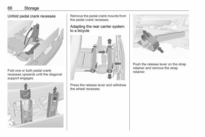
Unfold pedal crank recesses
Fold one or both pedal crankrecesses upwards until the diagonalsupport engages.
Remove the pedal crank mounts fromthe pedal crank recesses.
Adapting the rear carrier systemto a bicycle
Press the release lever and withdrawthe wheel recesses.
Push the release lever on the strapretainer and remove the strapretainer.
Storage 67
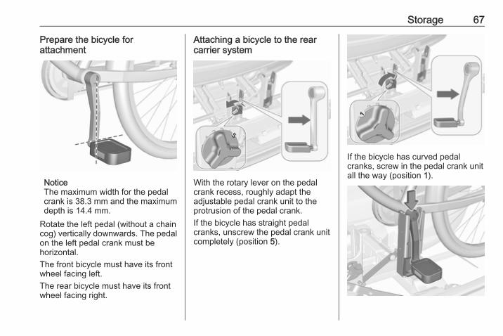
Prepare the bicycle forattachment
NoticeThe maximum width for the pedalcrank is 38.3 mm and the maximumdepth is 14.4 mm.
Rotate the left pedal (without a chaincog) vertically downwards. The pedalon the left pedal crank must behorizontal.The front bicycle must have its frontwheel facing left.The rear bicycle must have its frontwheel facing right.
Attaching a bicycle to the rearcarrier system
With the rotary lever on the pedalcrank recess, roughly adapt theadjustable pedal crank unit to theprotrusion of the pedal crank.If the bicycle has straight pedalcranks, unscrew the pedal crank unitcompletely (position 5).
If the bicycle has curved pedalcranks, screw in the pedal crank unitall the way (position 1).

68 Storage
Put on the bicycle. The pedal crankhere must be placed in the pedalcrank recess opening as shown in theillustration.
Caution
Make sure that the pedal does nottouch the surface of the rear endcarrier. Otherwise the cranksetmight be damaged during thetransport.
Insert pedal crank mount into outerrail of each pedal crank recess fromabove and slide downwards until atleast underneath the notching.
Attach the pedal crank by rotating theattachment screw on the pedal crankmount.
Place the wheel recesses so that thebicycle is roughly horizontal. Here,the distance between the pedals andthe tailgate should be at least 5 cm.Both bicycle tyres must be in thewheel recesses.
Caution
Make sure to pull out the wheelrecesses as far as necessary tohave both bicycle tyres placed inthe recesses. Otherwise ahorizontal mounting of the bicycleis not ensured. Disregard couldlead to damage of the bicyclewheels caused by hot exhaustfumes.

Storage 69
Align the bicycle in the longitudinaldirection of the vehicle: Slightlyloosen the pedal mount.Place the bicycle upright using therotary lever on the pedal crankrecess.If the two bicycles obstruct oneanother, the relative positions of thebicycles can be adapted by adjustingthe wheel recesses and the rotarylever on the pedal crank recess untilthe bicycles no longer touch oneanother. Make sure there is sufficientclearance from the vehicle.
Tighten the attachment screw for thepedal bearing mount to its maximumpoint by hand.Secure both bicycle wheels to wheelrecesses using strap retainers.Check the bicycle to make sure it issecure.
Caution
Ensure gap between bicycle andvehicle is at least 5 cm. Ifnecessary, loosen handlebar andswivel sideways.
The settings for the wheel recessesand on the rotary lever on the pedalcrank recess should be noted andsaved for each bicycle. Correctpresetting will facilitate refitting of thebicycle.NoticeIt is recommended to attach awarning sign at the rearmost bicycleto increase visibility.
Removing a bicycle from the rearcarrier system
Undo strap retainers on both bicycletyres.
70 Storage
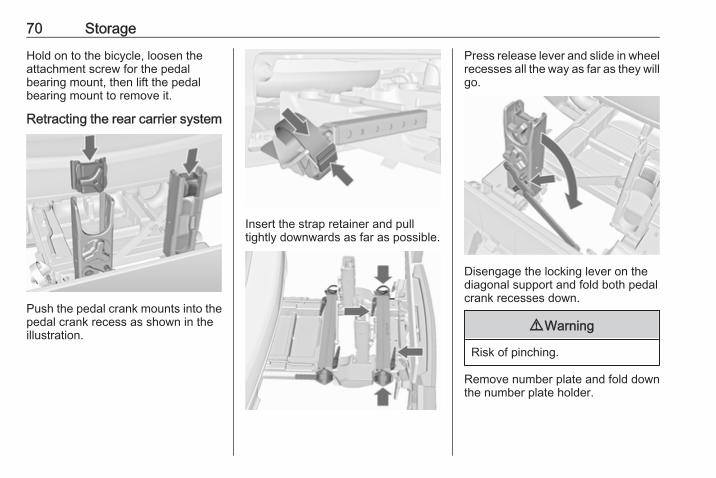
Hold on to the bicycle, loosen theattachment screw for the pedalbearing mount, then lift the pedalbearing mount to remove it.
Retracting the rear carrier system
Push the pedal crank mounts into thepedal crank recess as shown in theillustration.
Insert the strap retainer and pulltightly downwards as far as possible.
Press release lever and slide in wheelrecesses all the way as far as they willgo.
Disengage the locking lever on thediagonal support and fold both pedalcrank recesses down.
9 Warning
Risk of pinching.
Remove number plate and fold downthe number plate holder.

Storage 71
Swivel first the left clamping lever (1),followed by the right clamping lever(2), until they stop.
Push the clamping lever down andpull both lamp supports out of therecesses.
Fold in the lamp supports on thebacks of the tail lamps.First place the front tail lamp (1), thenthe rear tail lamp (2) in the recessesand push down as far as possible.Push cables all the way into all guidesin order to prevent damage.Open the tailgate.
Push the release lever up and hold.Lift the system slightly and push it intothe bumper until it engages.Release lever must return to originalposition.
9 Warning
If the system cannot be correctlyengaged, please seek theassistance of a workshop.
72 Storage
Load compartment
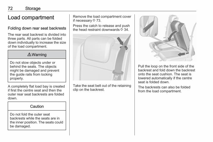
Folding down rear seat backrestsThe rear seat backrest is divided intothree parts. All parts can be foldeddown individually to increase the sizeof the load compartment.
9 Warning
Do not stow objects under orbehind the seats. The objectsmight be damaged and preventthe guide rails from lockingproperly.
A completely flat load bay is createdif first the centre seat and then theouter rear seat backrests are foldeddown.
Caution
Do not fold the outer seatbackrests while the seats are inthe inner position. The seats couldbe damaged.
Remove the load compartment coverif necessary 3 73.Press the catch to release and pushthe head restraint downwards 3 34.
Take the seat belt out of the retainingclip on the backrest.
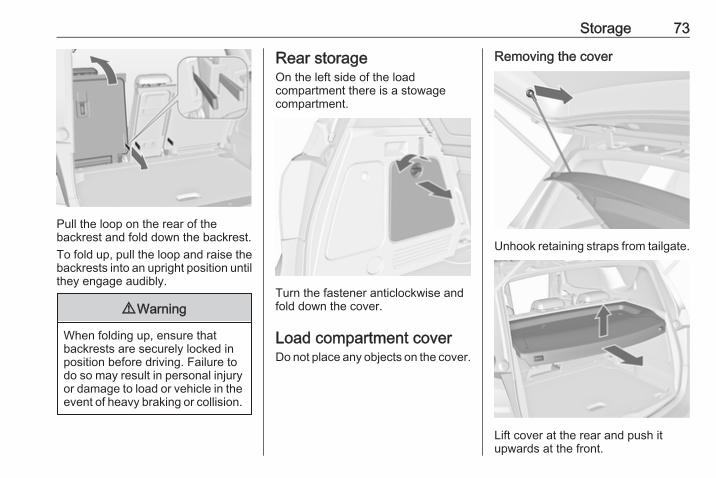
Pull the loop on the front side of thebackrest and fold down the backrestonto the seat cushion. The seat islowered automatically if the centreseat is folded down.The backrests can also be foldedfrom the load compartment.
Storage 73
Pull the loop on the rear of thebackrest and fold down the backrest.To fold up, pull the loop and raise thebackrests into an upright position untilthey engage audibly.
9 Warning
When folding up, ensure thatbackrests are securely locked inposition before driving. Failure todo so may result in personal injuryor damage to load or vehicle in theevent of heavy braking or collision.
Rear storageOn the left side of the loadcompartment there is a stowagecompartment.
Turn the fastener anticlockwise andfold down the cover.
Load compartment coverDo not place any objects on the cover.
Removing the cover
Unhook retaining straps from tailgate.
Lift cover at the rear and push itupwards at the front.
74 Storage
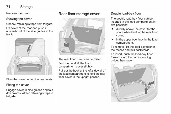
Remove the cover.
Stowing the coverUnhook retaining straps from tailgate.Lift cover at the rear and push itupwards out of the side guides at thefront.
Stow the cover behind the rear seats.
Fitting the coverEngage cover in side guides and folddownwards. Attach retaining straps totailgate.
Rear floor storage cover
The rear floor cover can be raised.Fold it up and lift the loadcompartment cover slightly.Pull out the hook at the left sidewall ofthe load compartment to hold the rearfloor cover in the upright positon.
Double load-bay floorThe double load-bay floor can beinserted in the load compartment intwo positions:● directly above the cover for the
spare wheel well or the rear floorcover,
● in the upper openings in the loadcompartment.
To remove, lift the load-bay floor atthe recess and pull backwards.To insert, push the load-bay floorforwards into the correspondingguide, then lower.

Storage 75
If mounted in the upper position, thespace between the load-bay floor andthe spare wheel well cover can beused as a stowage compartment.In this position, if the rear seatbackrests are folded forwards, analmost completely flat load bay iscreated.In the upper position, the double load-bay floor is able to withstand amaximum load of 100 kg. In the lowerposition, the double load-bay floor isable to withstand the maximumpermissible load.In models with a tyre repair kit, thespare wheel well may be used as anadditional storage compartment. Tyrerepair kit 3 201.Liquid gas shut-off valve 3 159.
Lashing eyes
The lashing eyes are designed tosecure items against slippage, e.g.using lashing straps or luggage net.
Safety netThe safety net can be installed behindthe front seats.Passengers must not be transportedbehind the safety net.
Installation
There are two installation openings inthe roof frame: suspend rod of net atone side, push to the front andengage. Extend rod, suspend at otherside, push to the front and engage.

76 Storage
Suspend hooks of net tensioningbelts in lashing eyes in the floorbehind the front seats. Tension thenet by pulling the loose end of the belt.Suspend and tighten on both sides.
RemovalTilt length adjuster of the nettensioning belts upwards and detachthe belts on both sides. Disengagethe upper rod on one side, disengageother side and remove from theopenings.
Stowage
Place tensioning straps as shown inillustration and align with safety net.
Roll the upper net rod down toapproximately over the middle.Place the upper net rod over thetensioning straps next to the lower netrod. The hooks on the upper net rodmust point away from the lower netrod.
Fasten Velcro tape tightly about thenet next to the length adjusters. Thelength adjusters and net rods must lieflat next to each other.Stow safety net in the space betweenthe double load-bay floor in the loadcompartment. Rear floor storagecover 3 74.
Storage 77
Folding trayLocated in the front seat backrests.Open by pulling upwards until itengages.Fold away by pressing down past theresistance point.Do not place any heavy objects on thefolding tray.
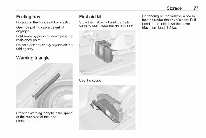
Warning triangle
Stow the warning triangle in the spaceat the rear side of the loadcompartment.
First aid kitStow the first aid kit and the highvisibility vest under the driver's seat.
Use the straps.
Depending on the vehicle, a box islocated under the driver's seat. Pullhandle and fold down the cover.Maximum load: 1.5 kg.
78 Storage
Roof rack systemRoof rackFor safety reasons and to avoiddamage to the roof, the vehicleapproved roof rack system isrecommended. For furtherinformation contact your workshop.Follow the installation instructionsand remove the roof rack when not inuse.
Detach the cover from each mountingpoint.
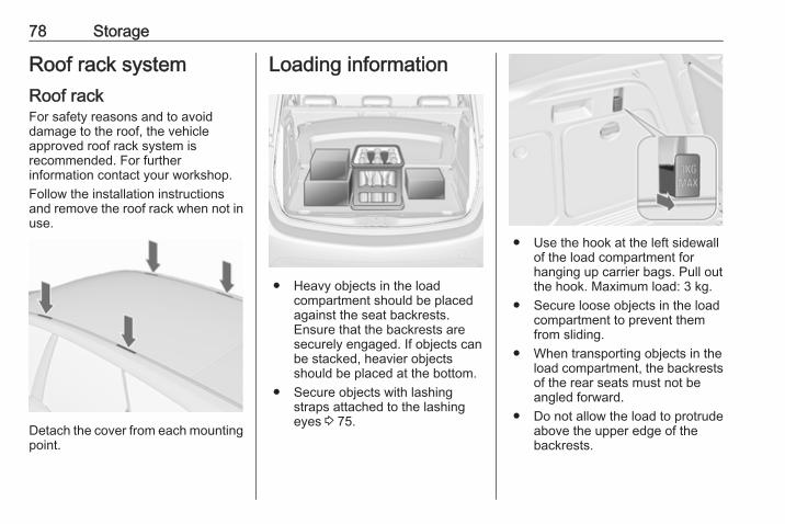
Loading information
● Heavy objects in the loadcompartment should be placedagainst the seat backrests.Ensure that the backrests aresecurely engaged. If objects canbe stacked, heavier objectsshould be placed at the bottom.
● Secure objects with lashingstraps attached to the lashingeyes 3 75.
● Use the hook at the left sidewallof the load compartment forhanging up carrier bags. Pull outthe hook. Maximum load: 3 kg.
● Secure loose objects in the loadcompartment to prevent themfrom sliding.
● When transporting objects in theload compartment, the backrestsof the rear seats must not beangled forward.
● Do not allow the load to protrudeabove the upper edge of thebackrests.

Storage 79
● Do not place any objects on theload compartment cover or theinstrument panel, and do notcover the sensor on top of theinstrument panel.
● The load must not obstruct theoperation of the pedals, parkingbrake and gear selector, orhinder the freedom of movementof the driver. Do not place anyunsecured objects in the interior.
● Do not drive with an open loadcompartment.
9 Warning
Always make sure that the load inthe vehicle is securely stowed.Otherwise objects can be thrownaround inside the vehicle andcause personal injury or damageto the load or vehicle.
● The payload is the differencebetween the permitted grossvehicle weight (see identificationplate 3 223) and the EC kerbweight.
To calculate the payload, enterthe data for your vehicle in theweights table at the front of thismanual.The EC kerb weight includesweights for the driver (68 kg),luggage (7 kg) and all fluids (fueltank 90% full).Optional equipment andaccessories increase the kerbweight.
● Driving with a roof load increasesthe sensitivity of the vehicle tocross-winds and has adetrimental effect on vehiclehandling due to the vehicle'shigher centre of gravity.Distribute the load evenly andsecure it properly with retainingstraps. Adjust the tyre pressureand vehicle speed according tothe load conditions. Check andretighten the straps frequently.Do not drive faster than 75 mph.The permissible roof load is60 kg. The roof load is thecombined weight of the roof rackand the load.
80 Instruments and controls
Instruments andcontrols
Controls ....................................... 81Steering wheel adjustment ........ 81Steering wheel controls ............. 81Heated steering wheel ............... 81Horn ........................................... 82Windscreen wiper/washer ......... 82Rear window wiper/washer ....... 84Outside temperature .................. 84Clock ......................................... 85Power outlets ............................. 86Cigarette lighter ......................... 87Ashtrays .................................... 87
Warning lights, gauges and indi‐cators ........................................... 88
Instrument cluster ...................... 88Speedometer ............................. 88Odometer .................................. 88Trip odometer ............................ 88Tachometer ............................... 88Fuel gauge ................................ 89Fuel selector .............................. 89Engine coolant temperaturegauge ....................................... 89
Service display .......................... 90
Control indicators ...................... 91Turn signal ................................. 93Seat belt reminder ..................... 94Airbag and belt tensioners ......... 94Airbag deactivation .................... 94Charging system ....................... 95Malfunction indicator light .......... 95Service vehicle soon ................. 95Brake and clutch system ........... 95Operate pedal ............................ 95Electric parking brake ................ 96Electric parking brake fault ........ 96Antilock brake system (ABS) ..... 96Upshift ....................................... 96Variable effort steering .............. 96Ultrasonic parking assist ........... 96Electronic Stability Control off . . . 97Electronic Stability Control andTraction Control system ........... 97
Traction Control system off ....... 97Preheating ................................. 97Diesel particle filter .................... 97Tyre pressure monitoringsystem ...................................... 97
Engine oil pressure .................... 98Low fuel ..................................... 98Immobiliser ................................ 98Reduced engine power ............. 98Exterior light .............................. 98High beam ................................. 99
Adaptive forward lighting ........... 99Fog light ..................................... 99Rear fog light ............................. 99Cruise control ............................ 99Door open .................................. 99Automatic locking ...................... 99
Information displays ................... 100Driver Information Centre ........ 100Graphic-Info-Display, Colour-Info-Display ............................ 103
Vehicle messages ...................... 105Warning chimes ....................... 107Battery voltage ........................ 108
Trip computer ............................. 108Vehicle personalisation .............. 111OnStar ....................................... 115

Instruments and controls 81
ControlsSteering wheel adjustment
Unlock lever, adjust steering wheel,then engage lever and ensure it isfully locked.Do not adjust steering wheel unlessvehicle is stationary and steeringwheel lock has been released.
Steering wheel controls
The Infotainment system, the cruisecontrol and a connected mobilephone can be operated via thecontrols on the steering wheel.Further information is available in theInfotainment manual.Cruise control 3 153.
Heated steering wheel
Activate heating by pressing *.Activation is indicated by the LED inthe button.
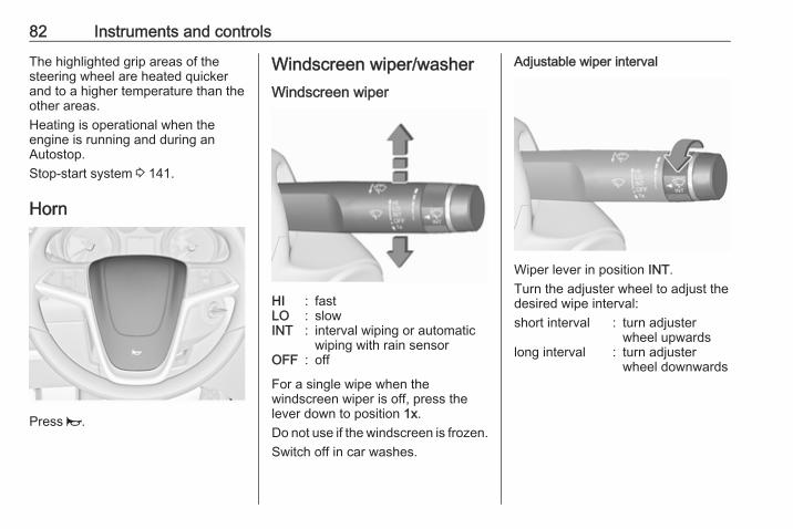
82 Instruments and controls
The highlighted grip areas of thesteering wheel are heated quickerand to a higher temperature than theother areas.Heating is operational when theengine is running and during anAutostop.Stop-start system 3 141.
Horn
Press j.
Windscreen wiper/washerWindscreen wiper
HI : fastLO : slowINT : interval wiping or automatic
wiping with rain sensorOFF : off
For a single wipe when thewindscreen wiper is off, press thelever down to position 1x.Do not use if the windscreen is frozen.Switch off in car washes.
Adjustable wiper interval
Wiper lever in position INT.Turn the adjuster wheel to adjust thedesired wipe interval:short interval : turn adjuster
wheel upwardslong interval : turn adjuster
wheel downwards
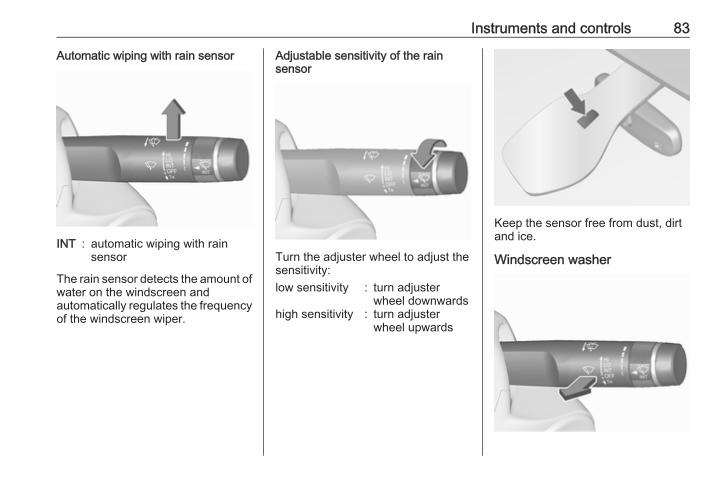
Instruments and controls 83
Automatic wiping with rain sensor
INT : automatic wiping with rainsensor
The rain sensor detects the amount ofwater on the windscreen andautomatically regulates the frequencyof the windscreen wiper.
Adjustable sensitivity of the rainsensor
Turn the adjuster wheel to adjust thesensitivity:low sensitivity : turn adjuster
wheel downwardshigh sensitivity : turn adjuster
wheel upwards
Keep the sensor free from dust, dirtand ice.
Windscreen washer
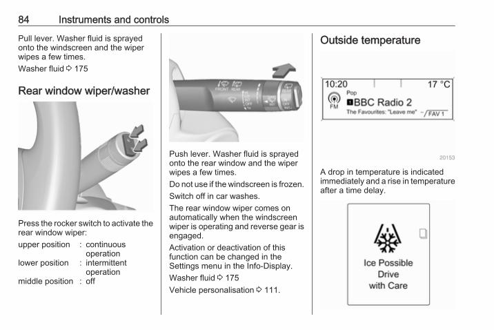
84 Instruments and controls
Pull lever. Washer fluid is sprayedonto the windscreen and the wiperwipes a few times.Washer fluid 3 175
Rear window wiper/washer
Press the rocker switch to activate therear window wiper:upper position : continuous
operationlower position : intermittent
operationmiddle position : off
Push lever. Washer fluid is sprayedonto the rear window and the wiperwipes a few times.Do not use if the windscreen is frozen.Switch off in car washes.The rear window wiper comes onautomatically when the windscreenwiper is operating and reverse gear isengaged.Activation or deactivation of thisfunction can be changed in theSettings menu in the Info-Display.Washer fluid 3 175Vehicle personalisation 3 111.
Outside temperature
A drop in temperature is indicatedimmediately and a rise in temperatureafter a time delay.

Instruments and controls 85
If outside temperature drops to 3 °C,a warning message is displayed in theDriver Information Centre withUplevel-Display orUplevel-Combi-Display.
9 Warning
The road surface may already beicy even though the displayindicates a few degrees above 0°C.
ClockDate and time are shown in theInfo-Display.
Time and date settingsCD 300/CD 400/CD 400plusPress CONFIG. The menu Settings isdisplayed.Select Time & Date.
Selectable setting options:● Set time: Changes the time
shown on the display.● Set date: Changes the date
shown on the display.● Set time format: Changes
indication of hours between 12hours and 24 hours.
● Set date format: Changesindication of date between MM/DD/YYYY and DD.MM.YYYY.
● Display digital clock: Switcheson/off indication of time on thedisplay.
● RDS clock synchronization: TheRDS signal of most VHFtransmitters automatically setsthe time. RDS timesynchronisation can take a fewminutes. Some transmitters donot send a correct time signal. Insuch cases, it is recommended toswitch off automatic timesynchronisation.
Vehicle personalisation 3 111.
Time and date settingsCD 600/Navi 650/Navi 950Press Config and then select theTime and Date menu item to displaythe respective submenu.
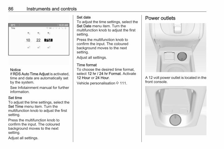
86 Instruments and controls
NoticeIf RDS Auto Time Adjust is activated,time and date are automatically setby the system.See Infotainment manual for furtherinformation.
Set timeTo adjust the time settings, select theSet Time menu item. Turn themultifunction knob to adjust the firstsetting.Press the multifunction knob toconfirm the input. The colouredbackground moves to the nextsetting.Adjust all settings.
Set dateTo adjust the time settings, select theSet Date menu item. Turn themultifunction knob to adjust the firstsetting.Press the multifunction knob toconfirm the input. The colouredbackground moves to the nextsetting.Adjust all settings.
Time formatTo choose the desired time format,select 12 hr / 24 hr Format. Activate12 Hour or 24 Hour.Vehicle personalisation 3 111.
Power outlets
A 12 volt power outlet is located in thefront console.
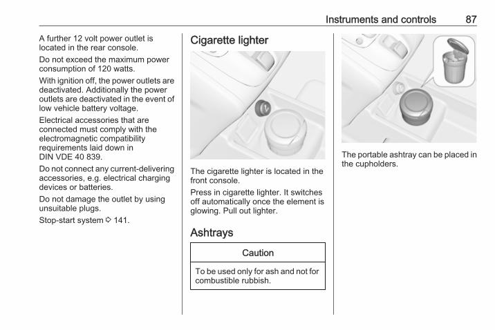
Instruments and controls 87
A further 12 volt power outlet islocated in the rear console.Do not exceed the maximum powerconsumption of 120 watts.With ignition off, the power outlets aredeactivated. Additionally the poweroutlets are deactivated in the event oflow vehicle battery voltage.Electrical accessories that areconnected must comply with theelectromagnetic compatibilityrequirements laid down inDIN VDE 40 839.Do not connect any current-deliveringaccessories, e.g. electrical chargingdevices or batteries.Do not damage the outlet by usingunsuitable plugs.Stop-start system 3 141.
Cigarette lighter
The cigarette lighter is located in thefront console.Press in cigarette lighter. It switchesoff automatically once the element isglowing. Pull out lighter.
Ashtrays
Caution
To be used only for ash and not forcombustible rubbish.
The portable ashtray can be placed inthe cupholders.

88 Instruments and controls
Warning lights, gaugesand indicatorsInstrument clusterIn some versions, the needles of theinstruments briefly rotate to the endposition when the ignition is switchedon.
Speedometer
Indicates vehicle speed.
Odometer
The bottom line displays the recordeddistance in miles.
Trip odometerThe top line displays the recordeddistance since the last reset.To reset, press SET/CLR on the turnsignal lever for a few seconds3 100.On vehicles with reset knob, hold thereset knob depressed for a fewseconds with the ignition on.
Tachometer
Displays the engine speed.Drive in a low engine speed range foreach gear as much as possible.
Caution
If the needle is in the red warningzone, the maximum permittedengine speed is exceeded. Engineat risk.
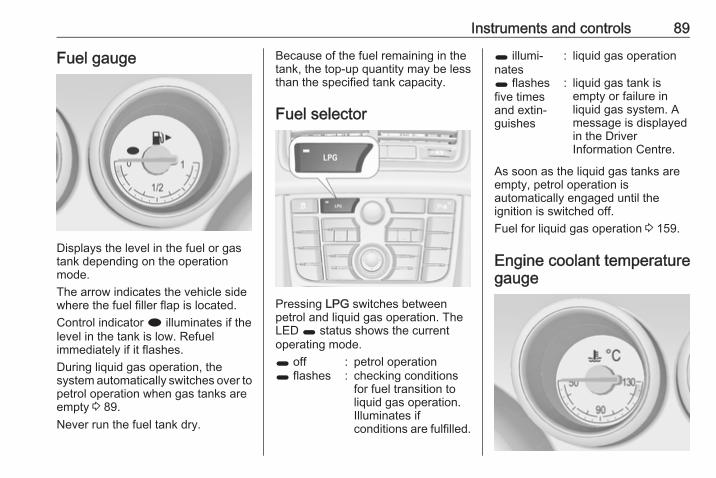
Instruments and controls 89
Fuel gauge
Displays the level in the fuel or gastank depending on the operationmode.The arrow indicates the vehicle sidewhere the fuel filler flap is located.Control indicator i illuminates if thelevel in the tank is low. Refuelimmediately if it flashes.During liquid gas operation, thesystem automatically switches over topetrol operation when gas tanks areempty 3 89.Never run the fuel tank dry.
Because of the fuel remaining in thetank, the top-up quantity may be lessthan the specified tank capacity.
Fuel selector
Pressing LPG switches betweenpetrol and liquid gas operation. TheLED 1 status shows the currentoperating mode.1 off : petrol operation1 flashes : checking conditions
for fuel transition toliquid gas operation.Illuminates ifconditions are fulfilled.
1 illumi‐nates
: liquid gas operation
1 flashesfive timesand extin‐guishes
: liquid gas tank isempty or failure inliquid gas system. Amessage is displayedin the DriverInformation Centre.
As soon as the liquid gas tanks areempty, petrol operation isautomatically engaged until theignition is switched off.Fuel for liquid gas operation 3 159.
Engine coolant temperaturegauge

90 Instruments and controls
Displays the coolant temperature.left area : engine operating
temperature not yetreached
centralarea
: normal operatingtemperature
right area : temperature too high
Caution
If engine coolant temperature istoo high, stop vehicle, switch offengine. Danger to engine. Checkcoolant level.
Service displayThe engine oil life system lets youknow when to change the engine oiland filter. Based on drivingconditions, the interval at which anengine oil and filter change will beindicated can vary considerably.
In the Uplevel-Display orUplevel-Combi-Display the remainingoil life duration is displayed in theVehicle Information Menu.In the Midlevel-Display the remainingengine oil life duration is displayed bythe control indicator I. The ignitionmust be switched on, with the enginenot running.The menu and function can beselected via the buttons on the turnsignal lever.To display the remaining engine oillife duration:
Press MENU to select the VehicleInformation Menu.Turn the adjuster wheel to selectRemaining Oil Life.The system must be reset every timethe engine oil is changed to allowproper functionality. Seek theassistance of a workshop.Press SET/CLR to reset. The ignitionmust be switched on, with the enginenot running.When the system has calculated thatengine oil life has been diminished,Change Engine Oil Soon or a warningcode appears in the DriverInformation Centre. Have engine oil

Instruments and controls 91
and filter changed by a workshopwithin one week or 300 miles(whichever occurs first).Driver Information Centre 3 100.Service information 3 219.
Control indicatorsThe control indicators described arenot present in all vehicles. Thedescription applies to all instrumentversions.Depending on the equipment theposition of the control indicators mayvary.When the ignition is switched on,most control indicators will illuminatebriefly as a functionality test.The control indicator colours mean:red : danger, important reminderyellow : warning, information, faultgreen : confirmation of activationblue : confirmation of activationwhite : confirmation of activation
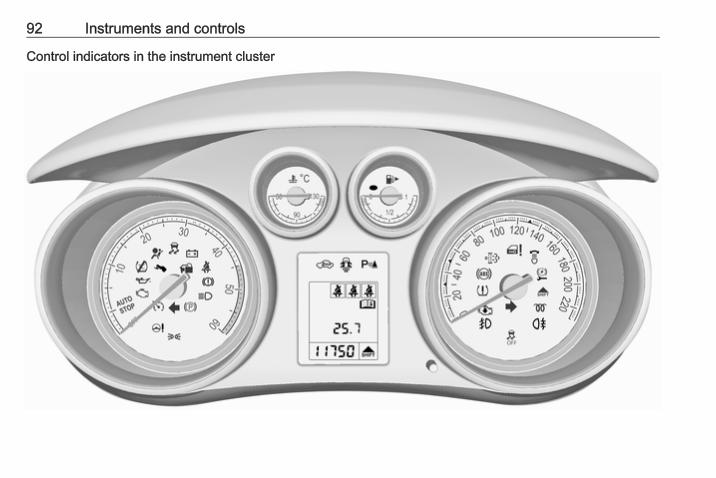
92 Instruments and controls
Control indicators in the instrument cluster

Instruments and controls 93
Control indicators in the centreconsole
Overview
O Turn signal 3 93
X Seat belt reminder 3 94
v Airbag and belt tensioners3 94
V Airbag deactivation 3 94
p Charging system 3 95
Z Malfunction indicator light3 95
g Service vehicle soon 3 95
R Brake and clutch system3 95
- Operate pedal 3 95
m Electric parking brake 3 96
j Electric parking brake fault3 96
u Antilock brake system (ABS)3 96
[ Upshift 3 96
c Variable effort steering 3 96
r Ultrasonic parking assist3 96
n Electronic Stability Control off3 97
b Electronic Stability Control andTraction Control system 3 97
k Traction Control system off3 97
! Preheating 3 97
% Diesel particle filter 3 97
w Tyre pressure monitoringsystem 3 97
I Engine oil pressure 3 98
i Low fuel 3 98
d Immobiliser 3 98
# Reduced engine power 3 98
8 Exterior light 3 98
C High beam 3 99
f Adaptive forward lighting3 99
> Fog light 3 99
r Rear fog light 3 99
m Cruise control 3 99
h Door open 3 99
^ Automatic locking 3 99
Turn signalO illuminates or flashes green.
Illuminates brieflyThe parking lights are switched on.
94 Instruments and controls
FlashesA turn signal or the hazard warningflashers are activated.Rapid flashing: failure of a turn signallight or associated fuse, failure of turnsignal light on trailer.Bulb replacement 3 179, Fuses3 188.Turn signals 3 123.
Seat belt reminderSeat belt reminder on front seatsX illuminates or flashes red.
IlluminatesAfter the ignition has been switchedon until the seat belt has beenfastened.
FlashesAfter having started the engine for amaximum of 100 seconds until theseat belt has been fastened.Fastening the seat belt 3 45.
Seat belt status on rear seats> or X in the Driver InformationCentre flashes or illuminates.
IlluminatesAfter having started the engine for aminimum of 35 seconds until the seatbelt has been fastened.If an unfastened seat belt is fastenedwhilst driving.
FlashesAfter starting off when the seat belt isunfastened.Fastening the seat belt 3 45.
Airbag and belt tensionersv illuminates red.When the ignition is switched on, thecontrol indicator illuminates forapprox. 4 seconds. If it does notilluminate, does not go out after4 seconds or illuminates whilstdriving, there is a fault in the airbagsystem. Seek the assistance of aworkshop. The airbags and beltpretensioners may fail to trigger in theevent of an accident.
Deployment of the belt pretensionersor airbags is indicated by continuousillumination of v.
9 Warning
Have the cause of the faultremedied immediately by aworkshop.
Belt pretensioners, airbag system3 44, 3 48.
Airbag deactivationV illuminates yellow.Illuminates for approx. 60 secondsafter the ignition is switched on. Thefront passenger airbag is activated.* illuminates yellow.The front passenger airbag isdeactivated 3 52.
Instruments and controls 95
9 Danger
Risk of fatal injury for a child usinga child restraint system togetherwith activated front passengerairbag.Risk of fatal injury for an adultperson with deactivated frontpassenger airbag.
Charging systemp illuminates red.Illuminates when the ignition isswitched on and extinguishes shortlyafter the engine starts.
Illuminates when the engine isrunningStop, switch off engine. Vehiclebattery is not charging. Enginecooling may be interrupted. Thebrake servo unit may cease to beeffective. Seek the assistance of aworkshop.
Malfunction indicator lightZ illuminates or flashes yellow.
Illuminates when the ignition isswitched on and extinguishes shortlyafter the engine starts.
Illuminates when the engine isrunningFault in the emission control system.The permitted emission limits may beexceeded. Seek the assistance of aworkshop immediately.
Flashes when the engine isrunningFault that could lead to catalyticconverter damage. Ease up on theaccelerator until the flashing stops.Seek the assistance of a workshopimmediately.
Service vehicle soong illuminates yellow.Additionally a warning message or awarning code is displayed.The vehicle needs a service.Seek the assistance of a workshop.Vehicle messages 3 105.
Brake and clutch systemBrake and clutch fluid levelR illuminates red.The brake and clutch fluid level is toolow 3 175.
9 Warning
Stop. Do not continue yourjourney. Consult a workshop.
Operate pedal- illuminates or flashes yellow.
IlluminatesBrake pedal needs to be depressedto release the electric parking brake3 150.Clutch pedal needs to be depressedto start the engine in Autostop mode.Stop-start system 3 141.
FlashesClutch pedal needs to be depressedfor a main start of the engine 3 16,3 140.

96 Instruments and controls
Electric parking brakem illuminates or flashes red.
IlluminatesElectrical parking brake is applied3 150.
FlashesElectrical parking brake is not fullyapplied or released. Switch onignition, depress brake pedal andattempt to reset the system by firstreleasing and then applying theelectrical parking brake. If m remainsflashing, do not drive and seek theassistance of a workshop.
Electric parking brake faultj illuminates or flashes yellow.
IlluminatesElectrical parking brake is operatingwith degraded performance 3 150.
FlashesElectrical parking brake is in servicemode. Stop vehicle, apply andrelease the electrical parking brake toreset.
9 Warning
Have the cause of the faultremedied immediately by aworkshop.
Antilock brake system(ABS)u illuminates yellow.Illuminates for a few seconds after theignition is switched on. The system isready for operation when the controlindicator extinguishes.If the control indicator does not go outafter a few seconds, or if it illuminateswhile driving, there is a fault in theABS. The brake system remainsoperational but without ABSregulation.Antilock brake system 3 149.
Upshift[ illuminates green when upshiftingis recommended for fuel savingreasons.On vehicles with Uplevel-Display orUplevel-Combi-Display, [ with thenumber of the recommended gear isshown in the bottom line of the DriverInformation Centre.
Variable effort steeringc illuminates yellow.Fault in variable effort steeringsystem. This may lead to a higher orlower steering effort. Consult aworkshop.Stop-start system 3 141.
Ultrasonic parking assistr illuminates yellow.Fault in systemorFault due to sensors that are dirty orcovered by ice or snowor

Instruments and controls 97
Interference due to external sourcesof ultrasound. Once the source ofinterference is removed, the systemwill operate normally.Have the cause of the fault in thesystem remedied by a workshop.Ultrasonic parking assist 3 155.
Electronic Stability Controloffn illuminates yellow.The system is deactivated.
Electronic Stability Controland Traction Control systemb illuminates or flashes yellow.
IlluminatesA fault in the system is present.Continued driving is possible. Drivingstability, however, may deterioratedepending on road surfaceconditions.Have the cause of the fault remediedby a workshop.
FlashesThe system is actively engaged.Engine output may be reduced andthe vehicle may be brakedautomatically to a small degree.Electronic Stability Control 3 152,Traction Control system 3 152.
Traction Control system offk illuminates yellow.The system is deactivated.
Preheating! illuminates yellow.Preheating of diesel engine isactivated. Only activates whenoutside temperature is low.
Diesel particle filter% illuminates or flashes yellow.The diesel particle filter requirescleaning.
Continue driving until %extinguishes. If possible do not allowengine speed to drop below2000 rpm.
IlluminatesThe diesel particle filter is full. Startcleaning process as soon aspossible.
FlashesThe maximum filling level of the filteris reached. Start cleaning processimmediately to avoid damage to theengine.Diesel particle filter 3 144.Stop-start system 3 141.
Tyre pressure monitoringsystemw illuminates or flashes yellow.
IlluminatesTyre pressure loss. Stop immediatelyand check tyre pressure.
98 Instruments and controls
FlashesFault in system or tyre withoutpressure sensor mounted (e.g. sparewheel). After 60-90 seconds thecontrol indicator illuminatescontinuously. Consult a workshop.Tyre pressure monitoring system3 197.
Engine oil pressureI illuminates red.Illuminates when the ignition isswitched on and extinguishes shortlyafter the engine starts.
Illuminates when the engine isrunning
Caution
Engine lubrication may beinterrupted. This may result indamage to the engine and/orlocking of the drive wheels.
1. Depress clutch.2. Select neutral gear, set selector
lever to N.
3. Move out of the flow of traffic asquickly as possible withoutimpeding other vehicles.
4. Switch off ignition.
9 Warning
When the engine is off,considerably more force is neededto brake and steer. During anAutostop the brake servo unit willstill be operational.Do not remove key until vehicle isstationary, otherwise the steeringwheel lock could engageunexpectedly.
Check oil level before seekingassistance of a workshop 3 173.
Low fueli illuminates or flashes yellow.
IlluminatesLevel in fuel tank is too low.Additionally a warning message isdisplayed on vehicles with Uplevel-Display.
FlashesFuel used up. Refuel immediately.Never run the tank dry.Additionally a warning message isdisplayed on vehicles with Midlevel-and Uplevel-Display.Refuelling 3 161.Catalytic converter 3 145.Bleeding the diesel fuel system3 178.
Immobiliserd flashes yellow.Fault in the immobiliser system. Theengine cannot be started.
Reduced engine power# illuminates yellow.The engine power is limited. Consulta workshop.
Exterior light8 illuminates green.The exterior lights are on 3 119.
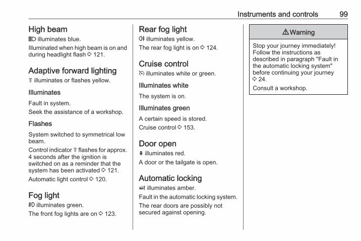
Instruments and controls 99
High beamC illuminates blue.Illuminated when high beam is on andduring headlight flash 3 121.
Adaptive forward lightingf illuminates or flashes yellow.
IlluminatesFault in system.Seek the assistance of a workshop.
FlashesSystem switched to symmetrical lowbeam.Control indicator f flashes for approx.4 seconds after the ignition isswitched on as a reminder that thesystem has been activated 3 121.Automatic light control 3 120.
Fog light> illuminates green.The front fog lights are on 3 123.
Rear fog lightr illuminates yellow.The rear fog light is on 3 124.
Cruise controlm illuminates white or green.
Illuminates whiteThe system is on.
Illuminates greenA certain speed is stored.Cruise control 3 153.
Door openh illuminates red.A door or the tailgate is open.
Automatic locking^ illuminates amber.Fault in the automatic locking system.The rear doors are possibly notsecured against opening.
9 Warning
Stop your journey immediately!Follow the instructions asdescribed in paragraph "Fault inthe automatic locking system"before continuing your journey3 24.Consult a workshop.
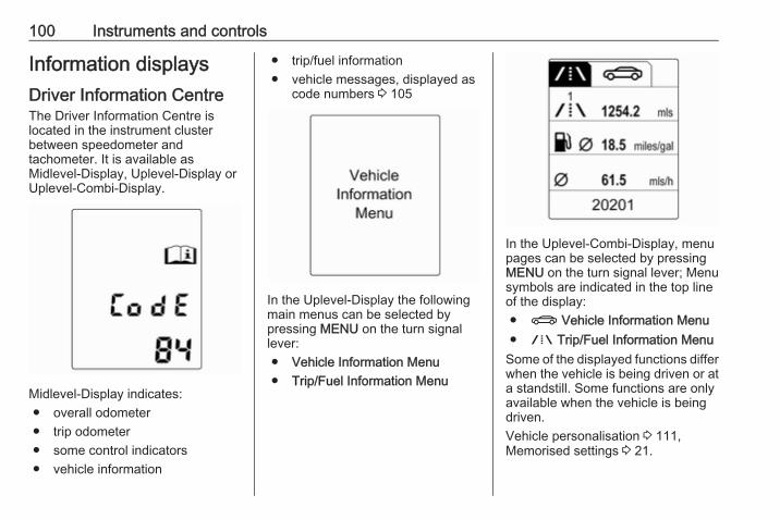
100 Instruments and controls
Information displaysDriver Information CentreThe Driver Information Centre islocated in the instrument clusterbetween speedometer andtachometer. It is available asMidlevel-Display, Uplevel-Display orUplevel-Combi-Display.
Midlevel-Display indicates:● overall odometer● trip odometer● some control indicators● vehicle information
● trip/fuel information● vehicle messages, displayed as
code numbers 3 105
In the Uplevel-Display the followingmain menus can be selected bypressing MENU on the turn signallever:● Vehicle Information Menu● Trip/Fuel Information Menu
In the Uplevel-Combi-Display, menupages can be selected by pressingMENU on the turn signal lever; Menusymbols are indicated in the top lineof the display:● X Vehicle Information Menu● W Trip/Fuel Information Menu
Some of the displayed functions differwhen the vehicle is being driven or ata standstill. Some functions are onlyavailable when the vehicle is beingdriven.Vehicle personalisation 3 111,Memorised settings 3 21.

Instruments and controls 101
Selecting menus and functionsThe menus and functions can beselected via the buttons on the turnsignal lever.
Press MENU to switch between themenus or to return from a submenu tothe next higher menu level.
Turn the adjuster wheel to highlight amenu option or to set a numeric value.
Press SET/CLR to select a function orto confirm a message.
Vehicle Information MenuPress MENU to select the VehicleInformation Menu, or on Uplevel-Combi-Display select X.Turn the adjuster wheel to select asubmenu. Press SET/CLR to confirm.Follow the instructions given in thesubmenus.Possible submenus can be,depending on the version:● Unit: Displayed units can be
changed.On vehicles with Midlevel-Display following settings can beselected:● Unit1: Great Britain● Unit2: United States● Unit3: Europe
● Tyre Pressure System: Checkstyre pressure of all wheels duringdriving 3 197.
● Tyre Load: Select tyre pressurecategory according to theactually inflated tyre pressure3 197.

102 Instruments and controls
● Remaining Oil Life: Indicateswhen to change the engine oiland filter 3 90.
● Speed Warning: If exceeding thepreset speed, a warning chimewill be activated.
● Language: Displayed languagecan be changed if the vehicle isnot equipped with a radio.
Selection and indication can bedifferent between Midlevel-, Uplevel-,and Uplevel-Combi-Display.
Trip/Fuel Information MenuPress MENU to select the Trip/FuelInformation Menu, or select W onUplevel-Combi-Display.Turn the adjuster wheel to select asubmenu. Press SET/CLR to confirm.
● trip odometer 1● trip odometer 2● digital speed
Trip odometer 2 and digital speed areonly available on vehicles withUplevel-Display or Uplevel-Combi-Display.Reset trip odometer by pressingSET/CLR on the turn signal lever fora few seconds or by pressing thereset knob between speedometerand Driver Information Centre withthe ignition on.On vehicles with trip computer moresubmenus are available.Selection and indication can bedifferent between Midlevel-, Uplevel-,and Uplevel-Combi-Display.Trip/Fuel Information Menu, TripComputer 3 108.
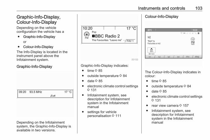
Instruments and controls 103
Graphic-Info-Display,Colour-Info-DisplayDepending on the vehicleconfiguration the vehicle has a● Graphic-Info-Display
or● Colour-Info-Display
The Info-Display is located in theinstrument panel above theInfotainment system.
Graphic-Info-Display
Depending on the Infotainmentsystem, the Graphic-Info-Display isavailable in two versions.
Graphic-Info-Display indicates:● time 3 85● outside temperature 3 84● date 3 85● electronic climate control settings
3 131● Infotainment system, see
description for Infotainmentsystem in the Infotainmentmanual
● settings for vehiclepersonalisation 3 111
Colour-Info-Display
The Colour-Info-Display indicates incolour:● time 3 85● outside temperature 3 84● date 3 85● electronic climate control settings
3 131● rear view camera 3 157● Infotainment system, see
description for Infotainmentsystem in the Infotainmentmanual
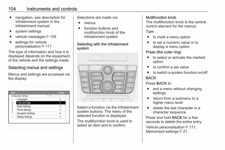
104 Instruments and controls
● navigation, see description forInfotainment system in theInfotainment manual
● system settings● vehicle messages 3 105● settings for vehicle
personalisation 3 111The type of information and how it isdisplayed depends on the equipmentof the vehicle and the settings made.
Selecting menus and settingsMenus and settings are accessed viathe display.
Selections are made via:● menus● function buttons and
multifunction knob of theInfotainment system
Selecting with the Infotainmentsystem
Select a function via the Infotainmentsystem buttons. The menu of theselected function is displayed.The multifunction knob is used toselect an item and to confirm.
Multifunction knobThe multifunction knob is the centralcontrol element for the menus:Turn● to mark a menu option● to set a numeric value or to
display a menu optionPress (the outer ring)● to select or activate the marked
option● to confirm a set value● to switch a system function on/off
BACKPress BACK to:● exit a menu without changing
settings● return from a submenu to a
higher menu level● delete the last character in a
character sequencePress and hold BACK for a fewseconds to delete the entire entry.Vehicle personalisation 3 111,Memorised settings 3 21.
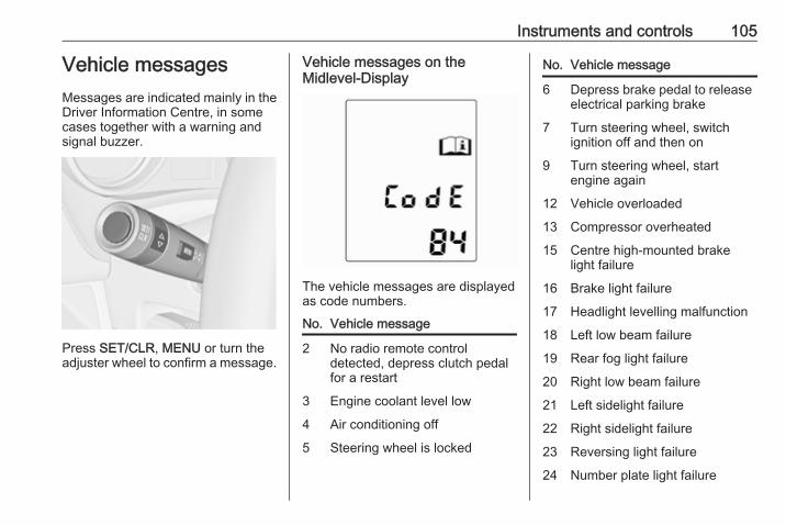
Instruments and controls 105
Vehicle messagesMessages are indicated mainly in theDriver Information Centre, in somecases together with a warning andsignal buzzer.
Press SET/CLR, MENU or turn theadjuster wheel to confirm a message.
Vehicle messages on theMidlevel-Display
The vehicle messages are displayedas code numbers.
No. Vehicle message
2 No radio remote controldetected, depress clutch pedalfor a restart
3 Engine coolant level low
4 Air conditioning off
5 Steering wheel is locked
No. Vehicle message
6 Depress brake pedal to releaseelectrical parking brake
7 Turn steering wheel, switchignition off and then on
9 Turn steering wheel, startengine again
12 Vehicle overloaded
13 Compressor overheated
15 Centre high-mounted brakelight failure
16 Brake light failure
17 Headlight levelling malfunction
18 Left low beam failure
19 Rear fog light failure
20 Right low beam failure
21 Left sidelight failure
22 Right sidelight failure
23 Reversing light failure
24 Number plate light failure
106 Instruments and controls
No. Vehicle message
25 Left front turn signal failure
26 Left rear turn signal failure
27 Right front turn signal failure
28 Right rear turn signal failure
29 Check trailer brake light
30 Check trailer reversing light
31 Check left trailer turn signal
32 Check right trailer turn signal
33 Check trailer rear fog light
34 Check trailer rear light
35 Replace battery in radio remotecontrol
48 Clean side blind zone alertsystem
53 Tighten gas cap
54 Water in diesel fuel filter
55 Diesel particle filter is full3 144
No. Vehicle message
56 Tyre pressure imbalance onfront axle
57 Tyre pressure imbalance onrear axle
58 Tyres without TPMS sensorsdetected
59 Open and then close driverwindow
60 Open and then close frontpassenger window
61 Open and then close rear leftwindow
62 Open and then close rear rightwindow
65 Theft attempted
66 Service theft alarm system
67 Service steering wheel lock
68 Service power steering
69 Service suspension system
70 Service level control system
No. Vehicle message
71 Service rear axle
74 Service AFL
75 Service air conditioning
76 Service side blind zone alertsystem
79 Top up engine oil
81 Service transmission
82 Change engine oil soon
83 Service adaptive cruise control
84 Engine power is reduced
89 Service vehicle soon
94 Shift to park before exiting
95 Service airbag
128 Bonnet open
134 Park assist fault, clean bumper
136 Service parking assist
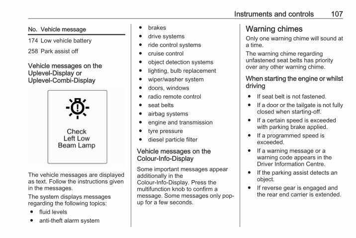
Instruments and controls 107
No. Vehicle message
174 Low vehicle battery
258 Park assist off
Vehicle messages on theUplevel-Display orUplevel-Combi-Display
The vehicle messages are displayedas text. Follow the instructions givenin the messages.The system displays messagesregarding the following topics:● fluid levels● anti-theft alarm system
● brakes● drive systems● ride control systems● cruise control● object detection systems● lighting, bulb replacement● wiper/washer system● doors, windows● radio remote control● seat belts● airbag systems● engine and transmission● tyre pressure● diesel particle filter
Vehicle messages on theColour-Info-DisplaySome important messages appearadditionally in theColour-Info-Display. Press themultifunction knob to confirm amessage. Some messages only pop-up for a few seconds.
Warning chimesOnly one warning chime will sound ata time.The warning chime regardingunfastened seat belts has priorityover any other warning chime.
When starting the engine or whilstdriving● If seat belt is not fastened.● If a door or the tailgate is not fully
closed when starting-off.● If a certain speed is exceeded
with parking brake applied.● If a programmed speed is
exceeded.● If a warning message or a
warning code appears in theDriver Information Centre.
● If the parking assist detects anobject.
● If reverse gear is engaged andthe rear end carrier is extended.
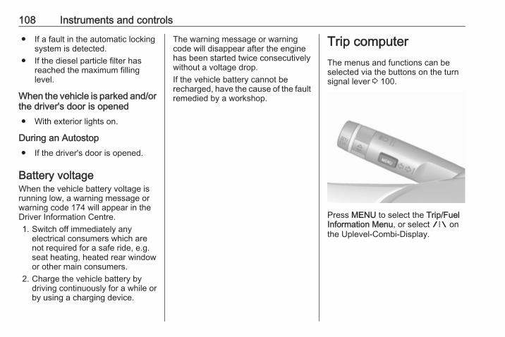
108 Instruments and controls
● If a fault in the automatic lockingsystem is detected.
● If the diesel particle filter hasreached the maximum fillinglevel.
When the vehicle is parked and/orthe driver's door is opened● With exterior lights on.
During an Autostop● If the driver's door is opened.
Battery voltageWhen the vehicle battery voltage isrunning low, a warning message orwarning code 174 will appear in theDriver Information Centre.1. Switch off immediately any
electrical consumers which arenot required for a safe ride, e.g.seat heating, heated rear windowor other main consumers.
2. Charge the vehicle battery bydriving continuously for a while orby using a charging device.
The warning message or warningcode will disappear after the enginehas been started twice consecutivelywithout a voltage drop.If the vehicle battery cannot berecharged, have the cause of the faultremedied by a workshop.
Trip computerThe menus and functions can beselected via the buttons on the turnsignal lever 3 100.
Press MENU to select the Trip/FuelInformation Menu, or select W onthe Uplevel-Combi-Display.
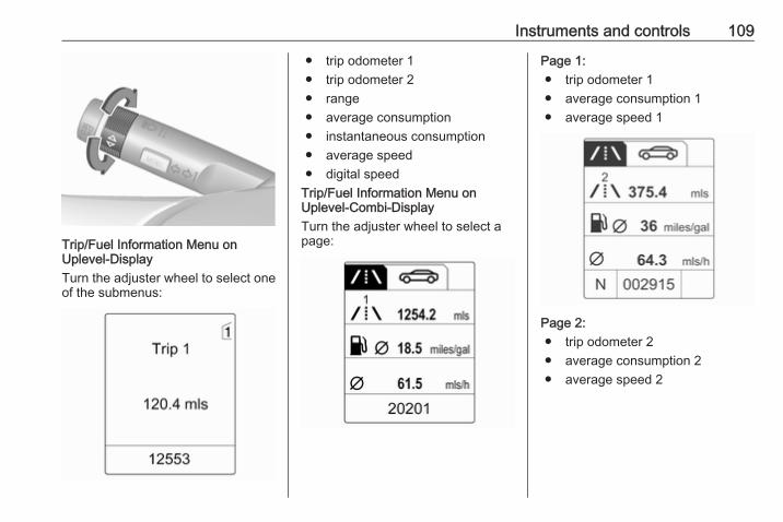
Instruments and controls 109
Trip/Fuel Information Menu onUplevel-DisplayTurn the adjuster wheel to select oneof the submenus:
● trip odometer 1● trip odometer 2● range● average consumption● instantaneous consumption● average speed● digital speed
Trip/Fuel Information Menu onUplevel-Combi-DisplayTurn the adjuster wheel to select apage:
Page 1:● trip odometer 1● average consumption 1● average speed 1
Page 2:● trip odometer 2● average consumption 2● average speed 2
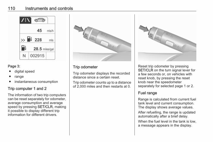
110 Instruments and controls
Page 3:● digital speed● range● instantaneous consumption
Trip computer 1 and 2The information of two trip computerscan be reset separately for odometer,average consumption and averagespeed by pressing SET/CLR, makingit possible to display different tripinformation for different drivers.
Trip odometerTrip odometer displays the recordeddistance since a certain reset.Trip odometer counts up to a distanceof 2,000 miles and then restarts at 0.
Reset trip odometer by pressingSET/CLR on the turn signal lever fora few seconds or, on vehicles withreset knob, by pressing the resetknob near the speedometerseparately for selected page 1 or 2.
Fuel rangeRange is calculated from current fueltank level and current consumption.The display shows average values.After refuelling, the range is updatedautomatically after a brief delay.When the fuel level in the tank is low,a message appears in the display.
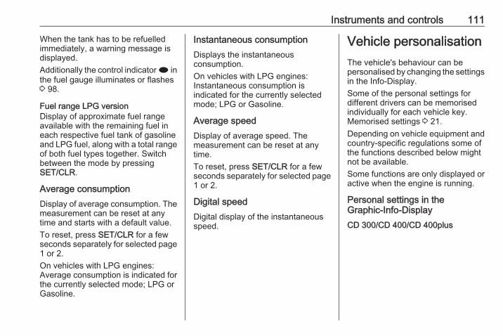
Instruments and controls 111
When the tank has to be refuelledimmediately, a warning message isdisplayed.Additionally the control indicator i inthe fuel gauge illuminates or flashes3 98.
Fuel range LPG versionDisplay of approximate fuel rangeavailable with the remaining fuel ineach respective fuel tank of gasolineand LPG fuel, along with a total rangeof both fuel types together. Switchbetween the mode by pressingSET/CLR.
Average consumptionDisplay of average consumption. Themeasurement can be reset at anytime and starts with a default value.To reset, press SET/CLR for a fewseconds separately for selected page1 or 2.On vehicles with LPG engines:Average consumption is indicated forthe currently selected mode; LPG orGasoline.
Instantaneous consumptionDisplays the instantaneousconsumption.On vehicles with LPG engines:Instantaneous consumption isindicated for the currently selectedmode; LPG or Gasoline.
Average speedDisplay of average speed. Themeasurement can be reset at anytime.To reset, press SET/CLR for a fewseconds separately for selected page1 or 2.
Digital speedDigital display of the instantaneousspeed.
Vehicle personalisationThe vehicle's behaviour can bepersonalised by changing the settingsin the Info-Display.Some of the personal settings fordifferent drivers can be memorisedindividually for each vehicle key.Memorised settings 3 21.Depending on vehicle equipment andcountry-specific regulations some ofthe functions described below mightnot be available.Some functions are only displayed oractive when the engine is running.
Personal settings in theGraphic-Info-DisplayCD 300/CD 400/CD 400plus
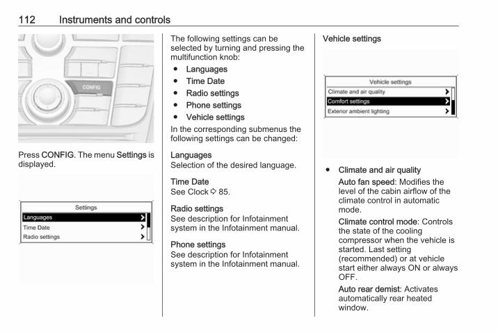
112 Instruments and controls
Press CONFIG. The menu Settings isdisplayed.
The following settings can beselected by turning and pressing themultifunction knob:● Languages● Time Date● Radio settings● Phone settings● Vehicle settings
In the corresponding submenus thefollowing settings can be changed:
LanguagesSelection of the desired language.
Time DateSee Clock 3 85.
Radio settingsSee description for Infotainmentsystem in the Infotainment manual.
Phone settingsSee description for Infotainmentsystem in the Infotainment manual.
Vehicle settings
● Climate and air qualityAuto fan speed: Modifies thelevel of the cabin airflow of theclimate control in automaticmode.Climate control mode: Controlsthe state of the coolingcompressor when the vehicle isstarted. Last setting(recommended) or at vehiclestart either always ON or alwaysOFF.Auto rear demist: Activatesautomatically rear heatedwindow.
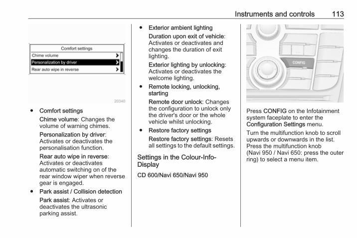
Instruments and controls 113
● Comfort settingsChime volume: Changes thevolume of warning chimes.Personalization by driver:Activates or deactivates thepersonalisation function.Rear auto wipe in reverse:Activates or deactivatesautomatic switching on of therear window wiper when reversegear is engaged.
● Park assist / Collision detectionPark assist: Activates ordeactivates the ultrasonicparking assist.
● Exterior ambient lightingDuration upon exit of vehicle:Activates or deactivates andchanges the duration of exitlighting.Exterior lighting by unlocking:Activates or deactivates thewelcome lighting.
● Remote locking, unlocking,startingRemote door unlock: Changesthe configuration to unlock onlythe driver's door or the wholevehicle whilst unlocking.
● Restore factory settingsRestore factory settings: Resetsall settings to the default settings.
Settings in the Colour-Info-DisplayCD 600/Navi 650/Navi 950
Press CONFIG on the Infotainmentsystem faceplate to enter theConfiguration Settings menu.Turn the multifunction knob to scrollupwards or downwards in the list.Press the multifunction knob(Navi 950 / Navi 650: press the outerring) to select a menu item.
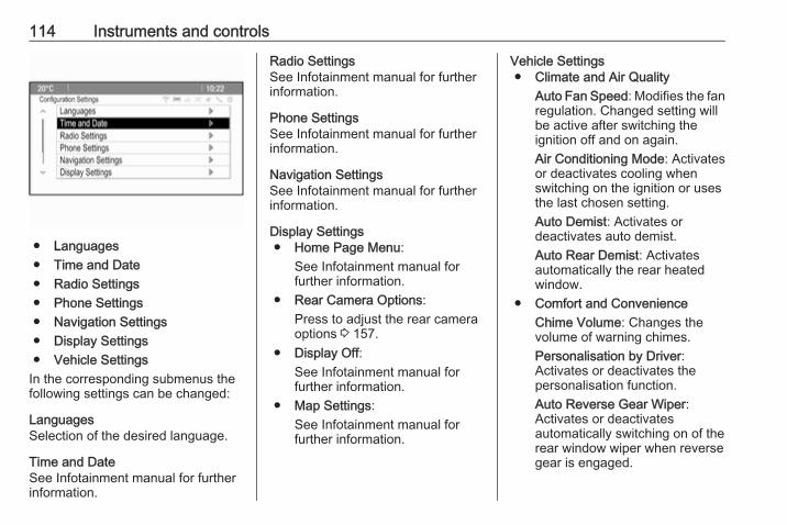
114 Instruments and controls
● Languages● Time and Date● Radio Settings● Phone Settings● Navigation Settings● Display Settings● Vehicle Settings
In the corresponding submenus thefollowing settings can be changed:
LanguagesSelection of the desired language.
Time and DateSee Infotainment manual for furtherinformation.
Radio SettingsSee Infotainment manual for furtherinformation.
Phone SettingsSee Infotainment manual for furtherinformation.
Navigation SettingsSee Infotainment manual for furtherinformation.
Display Settings● Home Page Menu:
See Infotainment manual forfurther information.
● Rear Camera Options:Press to adjust the rear cameraoptions 3 157.
● Display Off:See Infotainment manual forfurther information.
● Map Settings:See Infotainment manual forfurther information.
Vehicle Settings● Climate and Air Quality
Auto Fan Speed: Modifies the fanregulation. Changed setting willbe active after switching theignition off and on again.Air Conditioning Mode: Activatesor deactivates cooling whenswitching on the ignition or usesthe last chosen setting.Auto Demist: Activates ordeactivates auto demist.Auto Rear Demist: Activatesautomatically the rear heatedwindow.
● Comfort and ConvenienceChime Volume: Changes thevolume of warning chimes.Personalisation by Driver:Activates or deactivates thepersonalisation function.Auto Reverse Gear Wiper:Activates or deactivatesautomatically switching on of therear window wiper when reversegear is engaged.

Instruments and controls 115
● Collision Detection SystemsPark Assist: Activates ordeactivates the ultrasonicsensors.
● LightingVehicle Locator Lights: Activatesor deactivates the entry lighting.Exit Lighting: Activates ordeactivates and changes theduration of exit lighting.
● Remote Lock/Unlock/StartRemote Door Unlock: Changesthe configuration to unlock onlythe driver's door or the wholevehicle whilst unlocking.
● Return to Factory Settings?:Resets all settings to the defaultsettings.
OnStarOnStar is a personal connectivity andservice assistant with integratedWi-Fi hotspot. The OnStar service isavailable 24 hours a day, seven daysa week.NoticeOnStar is not available for allmarkets. For further information,contact your workshop.NoticeIn order to be available andoperational, OnStar needs a validOnStar subscription, functioningvehicle electrics, mobile service andGPS satellite link.
To activate the OnStar services andset up an account, press Z and speakwith an advisor.Depending on the equipment of thevehicle, the following services areavailable:● Emergency services and support
in the case of a vehiclebreakdown
● Wi-Fi hotspot
● Smartphone application● Remote control, e.g. location of
the vehicle, activation of horn andlights
● Stolen vehicle assistance● Vehicle diagnostics● Destination downloadNoticeThe OnStar module of the vehicle isdeactivated after ten days without anignition cycle. Functions requiring adata connection will be availableagain after switching on the ignition.
OnStar buttons
116 Instruments and controls
Privacy buttonPress and hold j until a message isheard to activate or deactivate thetransmission of the vehicle location.Press j to answer a call or to end acall to an advisor.Press j to access the Wi-Fi settings.
Service buttonPress Z to establish a connection toan advisor.
SOS buttonPress [ to establish a priorityemergency connection to a speciallytrained emergency advisor.
Status LEDGreen: The system is ready.Green flashing: The system is on acall.Red: A problem arose.Off: System is in standby mode.Red / green flashing for a short periodof time: Transmission of the vehiclelocation has been deactivated.
OnStar services
General servicesIf you need any informationconcerning e.g. opening hours, pointsof interest and destinations or if youneed any support e.g. in the case of avehicle breakdown, a flat tyre andempty fuel tank, press Z to establisha connection to an advisor.
Emergency servicesIn the case of an emergency situation,press [ and talk to an advisor. Theadvisor then contacts emergency orassistance service providers anddirects them to your vehicle.In the case of an accident withactivation of airbags or belttensioners, an automatic emergencycall is established. The advisor isimmediately connected to yourvehicle to see whether help isneeded.
Wi-Fi hotspotThe Wi-Fi hotspot of the vehicleprovides internet connectivity with amaximum speed of 4G/LTE.
NoticeThe Wi-Fi hotspot functionality is notavailable for all markets.
Up to seven devices may beconnected.To connect a mobile device with theWi-Fi hotspot:1. Press j and then select Wi-Fi
settings on the Info-Display. Thesettings displayed include the Wi-Fi hotspot name (SSID),password and connection type.
2. Start a Wi-Fi network search onyour mobile device.
3. Select your vehicle hotspot(SSID) when listed.
4. When prompted, enter thepassword on your mobile device.
NoticeTo change the SSID or password,press Z and talk to an advisor or login to your account.
To switch off the Wi-Fi hotspotfunctionality, press Z to call anadvisor.
Instruments and controls 117
Smartphone appWith the My Vauxhall smartphoneapp, some vehicle functions can beoperated remotely.The following functions are available:● Honk horn or flash lights.● Check fuel level and engine oil
life.● Send navigation destination to
the vehicle, if equipped with abuilt-in navigation system.
● Locate vehicle on a map.● Manage Wi-Fi settings.
To operate these functions, downloadthe app from Apple's App Store orGoogle Play Store.
Remote controlIf desired, use any phone to call anadvisor, who can remotely operatespecific vehicle functions. Find therespective OnStar phone number onour country-specific website.The following functions are available:● Provide information on the
vehicle location.● Honk horn or flash lights.
Stolen vehicle assistanceIf the vehicle is stolen, report the theftto the authorities and request OnStarstolen vehicle assistance. Use anyphone to call an advisor. Find therespective OnStar phone number onour country-specific website.OnStar can provide support inlocating and recovering the vehicle.Theft alertWhen the anti-theft alarm system istriggered, a notification is sent toOnStar. You are then informed aboutthis event by text message or email.
On-demand diagnosticsAt any time e.g. if the vehicle displaysa vehicle message, press Z tocontact an advisor and ask tocomplete a real-time diagnostic checkto directly determine the issue.Depending on the results, the advisorwill provide further support.
Diagnostic reportThe vehicle automatically transmitsdiagnostic data to OnStar whichsends a monthly email report to youand your preferred workshop.
NoticeThe workshop notification functioncan be disabled in your account.
The report contains the status of keyoperating systems of the vehicle likeengine, transmission, airbags, ABS,and other major systems. It alsoprovides information on possiblemaintenance items.To look at the information in greaterdetail, select the link within the emailand log in to your account.
Destination downloadA desired destination can be directlydownloaded to the navigation system.Press Z to call an advisor anddescribe the destination or point ofinterest.The advisor can look up any addressor point of interest and directly sendthe destination to the built-innavigation system.
118 Instruments and controls
OnStar settings
OnStar PINTo have full access to all OnStarservices, a four-digit PIN is required.The PIN has to be personalised whenfirst talking to an advisor.To change the PIN, press Z to call anadvisor.
Account dataAn OnStar subscriber has an accountwhere all the data is stored. Torequest a change of the accountinformation, press Z and talk to anadvisor or log in to your account.If the OnStar service is used onanother vehicle, press Z and requestthat the account be transferred to thenew vehicle.NoticeIn any case, if the vehicle is disposedof, sold or otherwise transferred,immediately inform OnStar aboutthe changes and terminate theOnStar service on this vehicle.
Vehicle locationThe vehicle location is transmitted toOnStar when service is requested ortriggered. A message on the Info-Display informs about thistransmission.To activate or deactivate thetransmission of the vehicle location,press and hold j until an audiomessage is heard.The deactivation is indicated by thestatus light flashing red and green fora short period of time and each timethe vehicle is started.NoticeIf the transmission of the vehiclelocation is deactivated, someservices are no longer available.NoticeThe vehicle location always remainsaccessible to OnStar in the case ofan emergency.
Find the privacy policy in youraccount.
Software updatesOnStar may remotely carry outsoftware updates without furthernotice or consent. These updates areto enhance or maintain safety andsecurity or the operation of thevehicle.These updates may concern privacyissues. Find the privacy policy in youraccount.
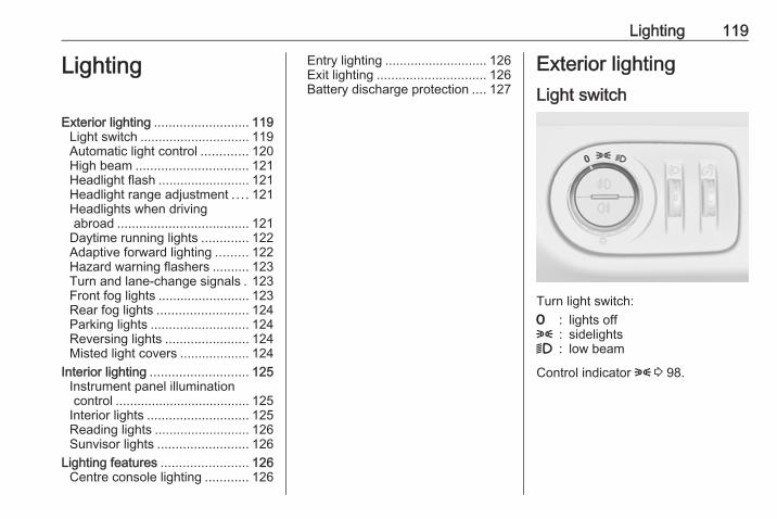
Lighting 119
Lighting
Exterior lighting .......................... 119Light switch .............................. 119Automatic light control ............. 120High beam ............................... 121Headlight flash ......................... 121Headlight range adjustment .... 121Headlights when drivingabroad .................................... 121
Daytime running lights ............. 122Adaptive forward lighting ......... 122Hazard warning flashers .......... 123Turn and lane-change signals . 123Front fog lights ......................... 123Rear fog lights ......................... 124Parking lights ........................... 124Reversing lights ....................... 124Misted light covers ................... 124
Interior lighting ........................... 125Instrument panel illuminationcontrol ..................................... 125
Interior lights ............................ 125Reading lights .......................... 126Sunvisor lights ......................... 126
Lighting features ........................ 126Centre console lighting ............ 126
Entry lighting ............................ 126Exit lighting .............................. 126Battery discharge protection .... 127
Exterior lightingLight switch
Turn light switch:7 : lights off8 : sidelights9 : low beam
Control indicator 8 3 98.
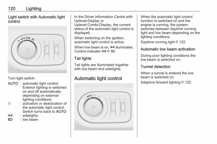
120 Lighting
Light switch with Automatic lightcontrol
Turn light switch:AUTO : automatic light control:
Exterior lighting is switchedon and off automaticallydepending on externallighting conditions
m : activation or deactivation ofthe automatic light control.Switch turns back to AUTO
8 : sidelights9 : low beam
In the Driver Information Centre withUplevel-Display orUplevel-Combi-Display, the currentstatus of the automatic light control isdisplayed.When switching on the ignition,automatic light control is active.When low beam is on, 8 illuminates.Control indicator 8 3 98.
Tail lightsTail lights are illuminated togetherwith low beam and sidelights.
Automatic light control
When the automatic light controlfunction is switched on and theengine is running, the systemswitches between daytime runninglight and low beam depending on thelighting conditions.Daytime running light 3 122.
Automatic low beam activationDuring poor lighting conditions thelow beam is switched on.
Tunnel detectionWhen a tunnel is entered the lowbeam is switched on.Adaptive forward lighting 3 122.

Lighting 121
High beam
To switch from low to high beam,push lever.To switch to low beam, push leveragain or pull.
Headlight flashTo activate the headlight flash, pulllever.
Headlight range adjustmentManual headlight rangeadjustment
To adapt headlight range to thevehicle load to prevent dazzling: turnthumb wheel ? to required position.0 : front seats occupied1 : all seats occupied2 : all seats occupied and load
compartment laden3 : driver's seat occupied and load
compartment laden
Headlights when drivingabroadThe asymmetrical headlight beamextends visibility at the edge of theroad on the front passenger side.However, when driving in countrieswhere traffic drives on the oppositeside of the road, adjust the headlightsto prevent dazzling of oncomingtraffic.
Vehicles without AdaptiveForward Lighting
Turn the adjusting screws clockwiseusing the screwdriver for half a turn.

122 Lighting
The adjusting screws are located atthe headlights above the low beamcaps 3 179.For deactivation, turn the adjustingscrews anticlockwise for half a turn.
Caution
Have the adjustment of theheadlights checked afterdeactivation.We recommend consulting aworkshop.
Vehicles with Adaptive ForwardLighting
1. Key in ignition switch.2. Pull turn signal lever and hold
(headlight flash).3. Switch on ignition.4. After approx. five seconds the
control indicator f starts flashingand an acoustic signal sounds.
Control indicator f 3 99.Every time the ignition is switched on,control indicator f flashes as areminder for approx. four seconds.For deactivation, operate the sameprocedure as described above.Control indicator f will not flash whenfunction is deactivated.
Daytime running lightsDaytime running light increasesvisibility of the vehicle during daylight.They are switched on automaticallywhen ignition is on.
Adaptive forward lightingAdaptive forward lighting ensuresbetter illumination of bends, crossingsand narrow bends.
Dynamic curve lighting
The light beam pivots based onsteering wheel angle and speed,improving lighting in curves.
Corner lighting
On tight bends or when turning off,depending on the steering angle orthe indicator light signal, an additionalleft or right reflector is switched onwhich illuminates the road in thedirection of travel. It is activated up toa speed of 25 mph.
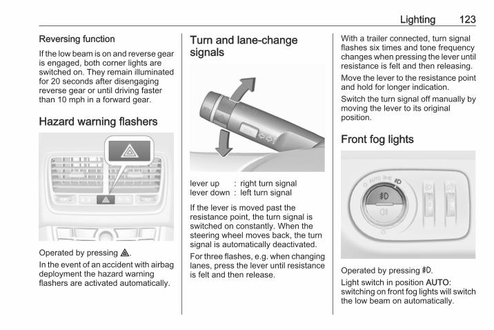
Lighting 123
Reversing functionIf the low beam is on and reverse gearis engaged, both corner lights areswitched on. They remain illuminatedfor 20 seconds after disengagingreverse gear or until driving fasterthan 10 mph in a forward gear.
Hazard warning flashers
Operated by pressing ¨.In the event of an accident with airbagdeployment the hazard warningflashers are activated automatically.
Turn and lane-changesignals
lever up : right turn signallever down : left turn signal
If the lever is moved past theresistance point, the turn signal isswitched on constantly. When thesteering wheel moves back, the turnsignal is automatically deactivated.For three flashes, e.g. when changinglanes, press the lever until resistanceis felt and then release.
With a trailer connected, turn signalflashes six times and tone frequencychanges when pressing the lever untilresistance is felt and then releasing.Move the lever to the resistance pointand hold for longer indication.Switch the turn signal off manually bymoving the lever to its originalposition.
Front fog lights
Operated by pressing >.Light switch in position AUTO:switching on front fog lights will switchthe low beam on automatically.

124 Lighting
Rear fog lights
Operated by pressing r.Light switch in position AUTO:switching on rear fog light will switchthe low beam on automatically.Light switch in position 8: rear foglight can only be switched on withfront fog lights.The vehicle rear fog light isdeactivated when towing.
Parking lights
When the vehicle is parked, theparking lights on one side can beactivated:1. Switch off ignition.2. Move turn signal lever all the way
up (right parking lights) or down(left parking lights).
Confirmed by a signal and thecorresponding turn signal controlindicator.
Reversing lightsThe reversing light comes on whenthe ignition is on and reverse gear isselected.
Misted light coversThe inside of the light housing maymist up briefly in poor, wet and coldweather conditions, in heavy rain orafter washing. The mist disappearsquickly by itself; to help switch on theexterior lights.
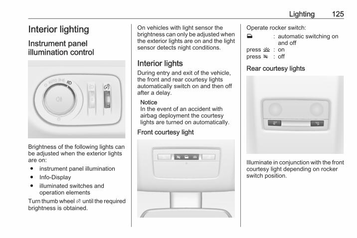
Lighting 125
Interior lightingInstrument panelillumination control
Brightness of the following lights canbe adjusted when the exterior lightsare on:● instrument panel illumination● Info-Display● illuminated switches and
operation elementsTurn thumb wheel A until the requiredbrightness is obtained.
On vehicles with light sensor thebrightness can only be adjusted whenthe exterior lights are on and the lightsensor detects night conditions.
Interior lightsDuring entry and exit of the vehicle,the front and rear courtesy lightsautomatically switch on and then offafter a delay.NoticeIn the event of an accident withairbag deployment the courtesylights are turned on automatically.
Front courtesy light
Operate rocker switch:w : automatic switching on
and offpress u : onpress v : off
Rear courtesy lights
Illuminate in conjunction with the frontcourtesy light depending on rockerswitch position.
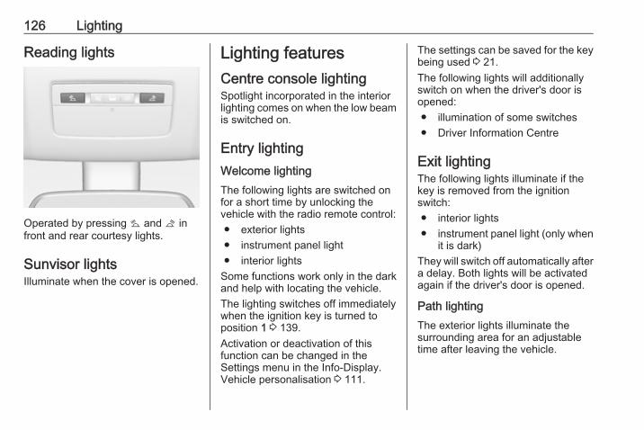
126 Lighting
Reading lights
Operated by pressing s and t infront and rear courtesy lights.
Sunvisor lightsIlluminate when the cover is opened.
Lighting featuresCentre console lightingSpotlight incorporated in the interiorlighting comes on when the low beamis switched on.
Entry lightingWelcome lightingThe following lights are switched onfor a short time by unlocking thevehicle with the radio remote control:● exterior lights● instrument panel light● interior lights
Some functions work only in the darkand help with locating the vehicle.The lighting switches off immediatelywhen the ignition key is turned toposition 1 3 139.Activation or deactivation of thisfunction can be changed in theSettings menu in the Info-Display.Vehicle personalisation 3 111.
The settings can be saved for the keybeing used 3 21.The following lights will additionallyswitch on when the driver's door isopened:● illumination of some switches● Driver Information Centre
Exit lightingThe following lights illuminate if thekey is removed from the ignitionswitch:● interior lights● instrument panel light (only when
it is dark)They will switch off automatically aftera delay. Both lights will be activatedagain if the driver's door is opened.
Path lightingThe exterior lights illuminate thesurrounding area for an adjustabletime after leaving the vehicle.

Lighting 127
Activating
1. Switch off ignition.2. Remove ignition key.3. Open driver's door.4. Pull turn signal lever.5. Close driver's door.
If the driver's door is not closed thelights switch off after 2 minutes.Exit lighting is switched offimmediately if the turn signal lever ispulled while the driver's door is open.Activation, deactivation and durationof this function can be changed in theSettings menu in the Info-Display.Vehicle personalisation 3 111.
The settings can be saved for the keybeing used 3 21.
Battery discharge protectionSwitching off electric lightsTo prevent discharge of the vehiclebattery when the ignition is switchedoff, some interior lights are switchedoff automatically after some time.
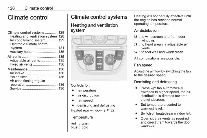
128 Climate control
Climate control
Climate control systems ............. 128Heating and ventilation system 128Air conditioning system ........... 129Electronic climate controlsystem .................................... 131
Auxiliary heater ........................ 135Air vents ..................................... 135
Adjustable air vents ................. 135Fixed air vents ......................... 136
Maintenance .............................. 136Air intake ................................. 136Pollen filter ............................... 136Air conditioning regularoperation ................................ 136
Service .................................... 136
Climate control systemsHeating and ventilationsystem
Controls for:● temperature● air distribution● fan speed● demisting and defrosting
Heated rear window Ü 3 32.
Temperaturered : warmblue : cold
Heating will not be fully effective untilthe engine has reached normaloperating temperature.
Air distributions : to windscreen and front door
windowsM : to head area via adjustable air
ventsK : to foot well and windscreen
All combinations are possible.
Fan speedAdjust the air flow by switching the fanto the desired speed.
Demisting and defrosting● Press V: fan automatically
switches to higher speed, the airdistribution is directed towardsthe windscreen.
● Set temperature control towarmest level.
● Switch on heated rear window Ü.● Open side air vents as required
and direct them towards the doorwindows.
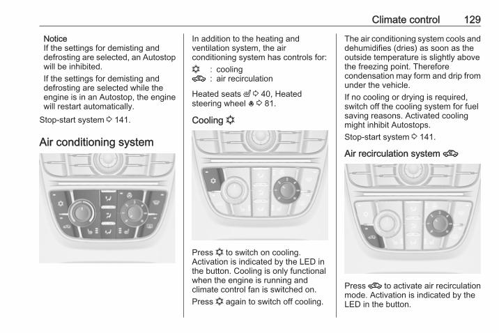
Climate control 129
NoticeIf the settings for demisting anddefrosting are selected, an Autostopwill be inhibited.If the settings for demisting anddefrosting are selected while theengine is in an Autostop, the enginewill restart automatically.
Stop-start system 3 141.
Air conditioning system
In addition to the heating andventilation system, the airconditioning system has controls for:n : cooling4 : air recirculation
Heated seats ß 3 40, Heatedsteering wheel * 3 81.
Cooling n
Press n to switch on cooling.Activation is indicated by the LED inthe button. Cooling is only functionalwhen the engine is running andclimate control fan is switched on.Press n again to switch off cooling.
The air conditioning system cools anddehumidifies (dries) as soon as theoutside temperature is slightly abovethe freezing point. Thereforecondensation may form and drip fromunder the vehicle.If no cooling or drying is required,switch off the cooling system for fuelsaving reasons. Activated coolingmight inhibit Autostops.Stop-start system 3 141.
Air recirculation system 4
Press 4 to activate air recirculationmode. Activation is indicated by theLED in the button.
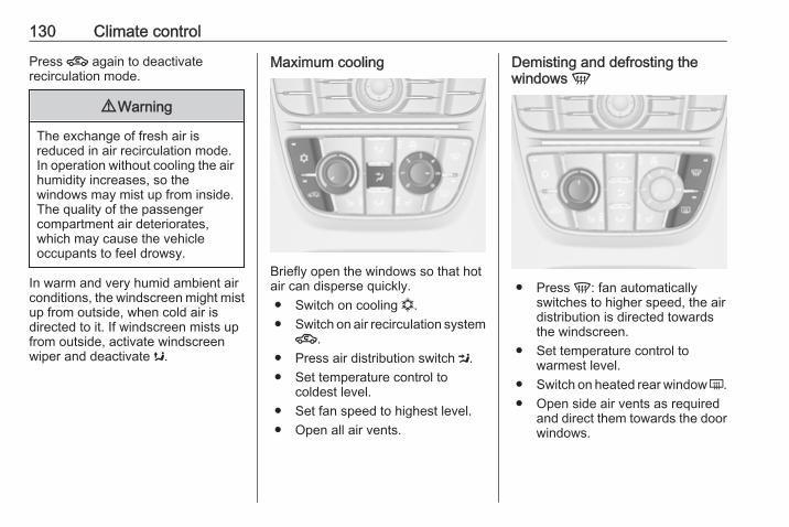
130 Climate control
Press 4 again to deactivaterecirculation mode.
9 Warning
The exchange of fresh air isreduced in air recirculation mode.In operation without cooling the airhumidity increases, so thewindows may mist up from inside.The quality of the passengercompartment air deteriorates,which may cause the vehicleoccupants to feel drowsy.
In warm and very humid ambient airconditions, the windscreen might mistup from outside, when cold air isdirected to it. If windscreen mists upfrom outside, activate windscreenwiper and deactivate s.
Maximum cooling
Briefly open the windows so that hotair can disperse quickly.● Switch on cooling n.● Switch on air recirculation system4.
● Press air distribution switch M.● Set temperature control to
coldest level.● Set fan speed to highest level.● Open all air vents.
Demisting and defrosting thewindows V
● Press V: fan automaticallyswitches to higher speed, the airdistribution is directed towardsthe windscreen.
● Set temperature control towarmest level.
● Switch on heated rear window Ü.● Open side air vents as required
and direct them towards the doorwindows.
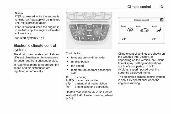
Climate control 131
NoticeIf V is pressed while the engine isrunning, an Autostop will be inhibiteduntil V is pressed again.If V is pressed while the engine isin an Autostop, the engine will restartautomatically.
Stop-start system 3 141.
Electronic climate controlsystemThe dual zone climate control allowsdifferent climatisation temperaturesfor driver and front passenger side.In Automatic mode temperature, fanspeed and air distribution areregulated automatically.
Controls for:● temperature on driver side● air distribution● fan speed● temperature on front passenger
siden : coolingAUTO : automatic mode4 : manual air recirculationV : demisting and defrosting
Heated rear window Ü 3 32, Heatedseats ß 3 40, Heated steering wheel* 3 81.
Climate control settings are shown onthe Graphic-Info-Display, ordepending on the version, on Colour-Info-Display. Setting modificationsare briefly popped-up in bothdisplays, superimposed over thecurrently displayed menu.The electronic climate control systemis only fully operational when theengine is running.

132 Climate control
Automatic mode AUTO
Basic setting for maximum comfort:● Press AUTO, the air distribution
and fan speed are regulatedautomatically.
● Open all air vents to allowoptimised air distribution inautomatic mode.
● Press n to switch on optimalcooling and demisting. Activationis indicated by the LED in thebutton.
● Set the preselectedtemperatures for driver and frontpassenger using the left and rightrotary knob. Recommendedtemperature is 22 °C.
The fan speed regulation in automaticmode can be changed in the menuSettings.Vehicle personalisation 3 111.
Temperature preselectionTemperatures can be set to thedesired value.
If the minimum temperature Lo is set,the climate control system runs atmaximum cooling, if cooling n isswitched on.If the maximum temperature Hi is set,the climate control system runs atmaximum heating.NoticeIf n is switched on, reducing the setcabin temperature can cause theengine to restart from an Autostop orinhibit an Autostop.
Stop-start system 3 141.
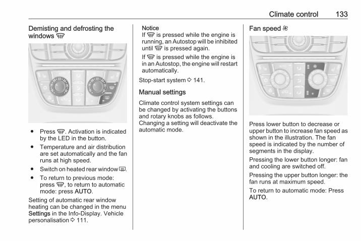
Climate control 133
Demisting and defrosting thewindows V
● Press V. Activation is indicatedby the LED in the button.
● Temperature and air distributionare set automatically and the fanruns at high speed.
● Switch on heated rear window Ü.● To return to previous mode:
press V, to return to automaticmode: press AUTO.
Setting of automatic rear windowheating can be changed in the menuSettings in the Info-Display. Vehiclepersonalisation 3 111.
NoticeIf V is pressed while the engine isrunning, an Autostop will be inhibiteduntil V is pressed again.If V is pressed while the engine isin an Autostop, the engine will restartautomatically.
Stop-start system 3 141.
Manual settingsClimate control system settings canbe changed by activating the buttonsand rotary knobs as follows.Changing a setting will deactivate theautomatic mode.
Fan speed Z
Press lower button to decrease orupper button to increase fan speed asshown in the illustration. The fanspeed is indicated by the number ofsegments in the display.Pressing the lower button longer: fanand cooling are switched off.Pressing the upper button longer: thefan runs at maximum speed.To return to automatic mode: PressAUTO.
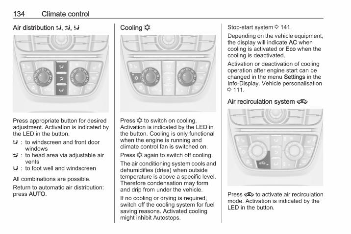
134 Climate control
Air distribution s, M, K
Press appropriate button for desiredadjustment. Activation is indicated bythe LED in the button.s : to windscreen and front door
windowsM : to head area via adjustable air
ventsK : to foot well and windscreen
All combinations are possible.Return to automatic air distribution:press AUTO.
Cooling n
Press n to switch on cooling.Activation is indicated by the LED inthe button. Cooling is only functionalwhen the engine is running andclimate control fan is switched on.Press n again to switch off cooling.The air conditioning system cools anddehumidifies (dries) when outsidetemperature is above a specific level.Therefore condensation may formand drip from under the vehicle.If no cooling or drying is required,switch off the cooling system for fuelsaving reasons. Activated coolingmight inhibit Autostops.
Stop-start system 3 141.Depending on the vehicle equipment,the display will indicate AC whencooling is activated or Eco when thecooling is deactivated.Activation or deactivation of coolingoperation after engine start can bechanged in the menu Settings in theInfo-Display. Vehicle personalisation3 111.
Air recirculation system 4
Press 4 to activate air recirculationmode. Activation is indicated by theLED in the button.

Climate control 135
Press 4 again to deactivaterecirculation mode.
9 Warning
The exchange of fresh air isreduced in air recirculation mode.In operation without cooling the airhumidity increases, so thewindows may mist up from inside.The quality of the passengercompartment air deteriorates,which may cause the vehicleoccupants to feel drowsy.
In warm and very humid ambient airconditions, the windscreen might mistup from outside, when cold air isdirected to it. If windscreen mists upfrom outside, activate windscreenwiper and deactivate s.
Basic settingsSome settings can be changed in theSettings menu in the Info-Display.Vehicle personalisation 3 111.
Auxiliary heaterAir heaterQuickheat is an electric auxiliary airheater which automatically warms upthe passenger compartment morequickly.
Air ventsAdjustable air vents
To open the vent, turn the adjusterwheel to the right. Adjust the airamount at the vent outlet by turningthe adjuster wheel.
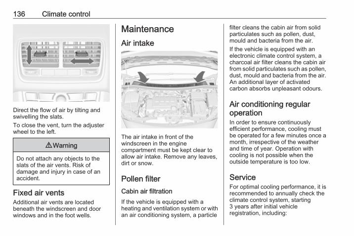
136 Climate control
Direct the flow of air by tilting andswivelling the slats.To close the vent, turn the adjusterwheel to the left.
9 Warning
Do not attach any objects to theslats of the air vents. Risk ofdamage and injury in case of anaccident.
Fixed air ventsAdditional air vents are locatedbeneath the windscreen and doorwindows and in the foot wells.
MaintenanceAir intake
The air intake in front of thewindscreen in the enginecompartment must be kept clear toallow air intake. Remove any leaves,dirt or snow.
Pollen filterCabin air filtrationIf the vehicle is equipped with aheating and ventilation system or withan air conditioning system, a particle
filter cleans the cabin air from solidparticulates such as pollen, dust,mould and bacteria from the air.If the vehicle is equipped with anelectronic climate control system, acharcoal air filter cleans the cabin airfrom solid particulates such as pollen,dust, mould and bacteria from the air.An additional layer of activatedcarbon absorbs unpleasant odours.
Air conditioning regularoperationIn order to ensure continuouslyefficient performance, cooling mustbe operated for a few minutes once amonth, irrespective of the weatherand time of year. Operation withcooling is not possible when theoutside temperature is too low.
ServiceFor optimal cooling performance, it isrecommended to annually check theclimate control system, starting3 years after initial vehicleregistration, including:
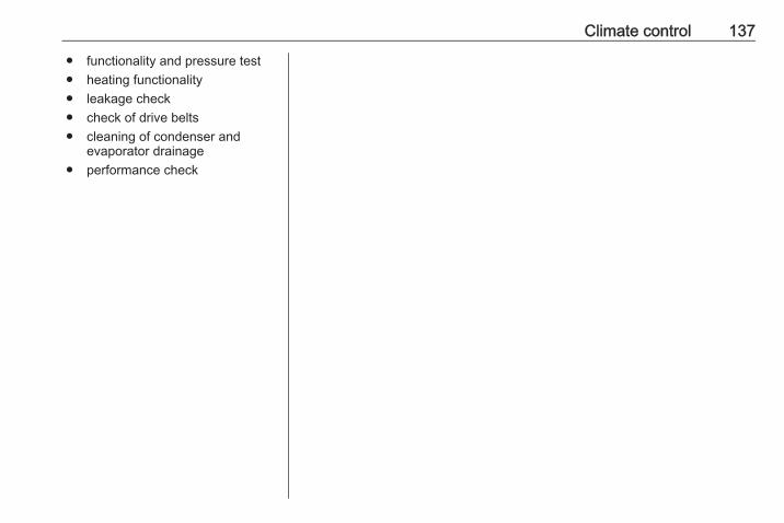
Climate control 137
● functionality and pressure test● heating functionality● leakage check● check of drive belts● cleaning of condenser and
evaporator drainage● performance check
138 Driving and operating
Driving andoperating
Driving hints ............................... 138Control of the vehicle ............... 138Steering ................................... 139
Starting and operating ............... 139New vehicle running-in ............ 139Ignition switch positions ........... 139Retained power off .................. 139Starting the engine .................. 140Overrun cut-off ........................ 141Stop-start system .................... 141Parking .................................... 143
Engine exhaust .......................... 144Diesel particle filter .................. 144Catalytic converter ................... 145
Automatic transmission .............. 145Transmission display ............... 145Selector lever .......................... 146Manual mode ........................... 147Electronic driving programmes 147Fault ........................................ 147Interruption of power supply .... 147
Manual transmission .................. 148
Brakes ........................................ 149Antilock brake system ............. 149Parking brake .......................... 150Brake assist ............................. 151Hill start assist ......................... 151
Ride control systems ................. 152Traction Control system .......... 152Electronic Stability Control ...... 152
Driver assistance systems ......... 153Cruise control .......................... 153Parking assist .......................... 155Rear view camera ................... 157
Fuel ............................................ 159Fuel for petrol engines ............. 159Fuel for diesel engines ............ 159Fuel for liquid gas operation .... 159Refuelling ................................ 161Fuel consumption - CO2-Emissions .............................. 164
Trailer hitch ................................ 165General information ................. 165Driving characteristics andtowing tips .............................. 166
Trailer towing ........................... 166Towing equipment ................... 167
Driving hintsControl of the vehicleNever coast with engine notrunning (except during Autostop)Many systems will not function in thissituation (e.g. brake servo unit, powersteering). Driving in this manner is adanger to yourself and others. Allsystems function during an Autostop,but there will be a controlled reductionin power steering assist and vehiclespeed is reduced.Stop-start system 3 141.
Idle boostIf charging of the vehicle battery isrequired due to vehicle batterycondition, the power output of thegenerator must be increased. This willbe achieved by an idle boost whichmay be audible.On vehicles with Uplevel-Display orUplevel-Combi-Display, a messageappears in the Driver InformationCentre.
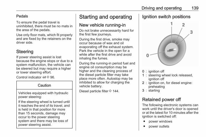
Driving and operating 139
PedalsTo ensure the pedal travel isuninhibited, there must be no mats inthe area of the pedals.Use only floor mats, which fit properlyand are fixed by the retainers on thedriver side.
SteeringIf power steering assist is lostbecause the engine stops or due to asystem malfunction, the vehicle canbe steered but may require a higheror lower steering effort.Control indicator c 3 96.
Caution
Vehicles equipped with hydraulicpower steering:If the steering wheel is turned untilit reaches the end of its travel, andis held in that position for morethan 15 seconds, damage mayoccur to the power steeringsystem and there may be loss ofpower steering assist.
Starting and operatingNew vehicle running-inDo not brake unnecessarily hard forthe first few journeys.During the first drive, smoke mayoccur because of wax and oilevaporating off the exhaust system.Park the vehicle in the open for awhile after the first drive and avoidinhaling the fumes.During the running-in period fuel andengine oil consumption may behigher and the cleaning process ofthe diesel particle filter may takeplace more often. Autostop may beinhibited to allow for charging thevehicle battery.Diesel particle filter 3 144.
Ignition switch positions
0 : ignition off1 : steering wheel lock released,
ignition off2 : ignition on, for diesel engine:
preheating3 : starting
Retained power offThe following electronic systems canwork until the driver's door is openedor at the latest for 10 minutes after theignition is switched off:● power windows● power outlets
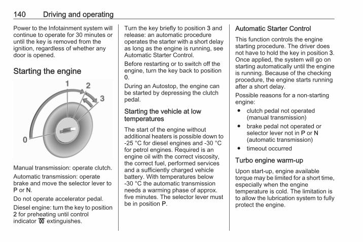
140 Driving and operating
Power to the Infotainment system willcontinue to operate for 30 minutes oruntil the key is removed from theignition, regardless of whether anydoor is opened.
Starting the engine
Manual transmission: operate clutch.Automatic transmission: operatebrake and move the selector lever toP or N.Do not operate accelerator pedal.Diesel engine: turn the key to position2 for preheating until controlindicator ! extinguishes.
Turn the key briefly to position 3 andrelease: an automatic procedureoperates the starter with a short delayas long as the engine is running, seeAutomatic Starter Control.Before restarting or to switch off theengine, turn the key back to position0.During an Autostop, the engine canbe started by depressing the clutchpedal.
Starting the vehicle at lowtemperaturesThe start of the engine withoutadditional heaters is possible down to-25 °С for diesel engines and -30 °Cfor petrol engines. Required is anengine oil with the correct viscosity,the correct fuel, performed servicesand a sufficiently charged vehiclebattery. With temperatures below-30 °C the automatic transmissionneeds a warming phase of approx.five minutes. The selector lever mustbe in position P.
Automatic Starter ControlThis function controls the enginestarting procedure. The driver doesnot have to hold the key in position 3.Once applied, the system will go onstarting automatically until the engineis running. Because of the checkingprocedure, the engine starts runningafter a short delay.Possible reasons for a non-startingengine:● clutch pedal not operated
(manual transmission)● brake pedal not operated or
selector lever not in P or N(automatic transmission)
● timeout occurred
Turbo engine warm-upUpon start-up, engine availabletorque may be limited for a short time,especially when the enginetemperature is cold. The limitation isto allow the lubrication system to fullyprotect the engine.
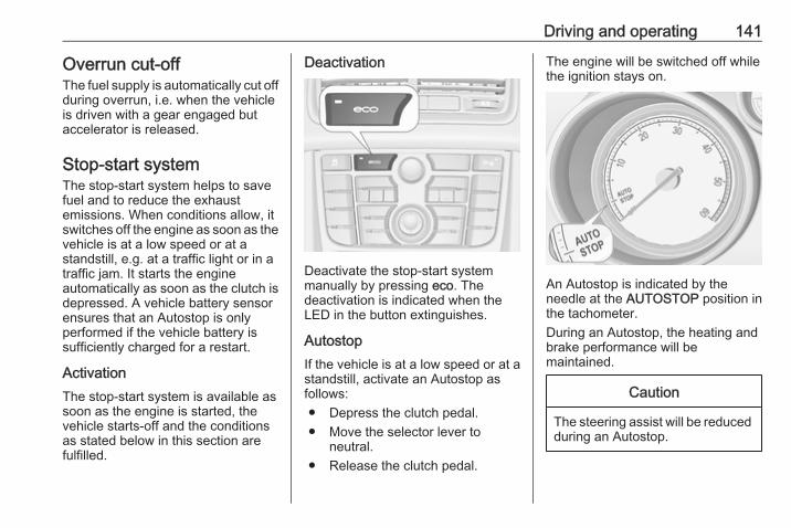
Driving and operating 141
Overrun cut-offThe fuel supply is automatically cut offduring overrun, i.e. when the vehicleis driven with a gear engaged butaccelerator is released.
Stop-start systemThe stop-start system helps to savefuel and to reduce the exhaustemissions. When conditions allow, itswitches off the engine as soon as thevehicle is at a low speed or at astandstill, e.g. at a traffic light or in atraffic jam. It starts the engineautomatically as soon as the clutch isdepressed. A vehicle battery sensorensures that an Autostop is onlyperformed if the vehicle battery issufficiently charged for a restart.
ActivationThe stop-start system is available assoon as the engine is started, thevehicle starts-off and the conditionsas stated below in this section arefulfilled.
Deactivation
Deactivate the stop-start systemmanually by pressing eco. Thedeactivation is indicated when theLED in the button extinguishes.
AutostopIf the vehicle is at a low speed or at astandstill, activate an Autostop asfollows:● Depress the clutch pedal.● Move the selector lever to
neutral.● Release the clutch pedal.
The engine will be switched off whilethe ignition stays on.
An Autostop is indicated by theneedle at the AUTOSTOP position inthe tachometer.During an Autostop, the heating andbrake performance will bemaintained.
Caution
The steering assist will be reducedduring an Autostop.
142 Driving and operating
Conditions for an AutostopThe stop-start system checks if eachof the following conditions is fulfilled:● The stop-start system is not
manually deactivated.● The bonnet is fully closed.● The driver's door is closed or the
driver's seat belt is fastened.● The vehicle battery is sufficiently
charged and in good condition.● The engine is warmed up.● The engine coolant temperature
is not too high.● The engine exhaust temperature
is not too high, e.g. after drivingwith high engine load.
● The ambient temperature isabove -5 °C.
● The defrost selection does notinhibit an Autostop.
● The climate control systemallows an Autostop.
● The brake vacuum is sufficient.
● The self-cleaning function of thediesel particle filter is not active.
● The vehicle was driven at least atwalking speed since the lastAutostop.
Otherwise an Autostop will beinhibited.An Autostop may become lessavailable as the ambient temperatureapproaches the freezing point.Certain settings of the climate controlsystem may inhibit an Autostop. See"Climate control" chapter for furtherinformation 3 131.Immediately after motorway drivingan Autostop may be inhibited.New vehicle running-in 3 139.
Vehicle battery discharge protectionTo ensure reliable engine restarts,several vehicle battery dischargeprotection features are implementedas part of the stop-start system.
Power saving measuresDuring an Autostop, several electricalfeatures such as auxiliary electricheater or rear window heating are
disabled or switched into a powersaving mode. The fan speed of theclimate control system is reduced tosave power.
Restart of the engine by the driverDepress the clutch pedal to restart theengine.The engine start is indicated by theneedle at the idle speed position inthe tachometer.If the selector lever is shifted out ofneutral before depressing the clutchfirst, control indicator - illuminatesor is shown as a symbol in the DriverInformation Centre.Control indicator - 3 95.
Restart of the engine by the stop-start systemThe selector lever must be in neutralto enable an automatic restart.If one of the following conditionsoccurs during an Autostop, theengine will be restarted automaticallyby the stop-start system.
Driving and operating 143
● The stop-start system ismanually deactivated.
● The bonnet is opened.● The driver's seat belt is
unfastened and the driver's dooris opened.
● The engine temperature is toolow.
● The charging level of the vehiclebattery is below a defined level.
● The brake vacuum is notsufficient.
● The vehicle is driven at least atwalking speed.
● The climate control systemrequests an engine start.
● The air conditioning is manuallyswitched on.
If the bonnet is not fully closed, awarning message is displayed in theDriver Information Centre.If an electrical accessory, e.g. aportable CD player, is connected tothe power outlet, a brief power dropduring the restart might be noticeable.
Parking
9 Warning
● Do not park the vehicle on aneasily ignitable surface. Thehigh temperature of theexhaust system could ignite thesurface.
● Always apply parking brake.Pull switch m for approx.one second.The electric parking brake isapplied when control indicatorm illuminates 3 95.
● Switch off the engine.● If the vehicle is on a level
surface or uphill slope, engagefirst gear or set the selectorlever to position P beforeremoving the ignition key. Onan uphill slope, turn the frontwheels away from the kerb.If the vehicle is on a downhillslope, engage reverse gear orset the selector lever to positionP before removing the ignition
key. Turn the front wheelstowards the kerb.
● Close the windows.● Remove the ignition key from
the ignition switch. Turn thesteering wheel until thesteering wheel lock is felt toengage.For vehicles with automatictransmission, the key can onlybe removed when the selectorlever is in position P.
Lock the vehicle and activate the anti-theft alarm system.NoticeIn the event of an accident withairbag deployment, the engine isturned off automatically if the vehiclecomes to a standstill within a certaintime.
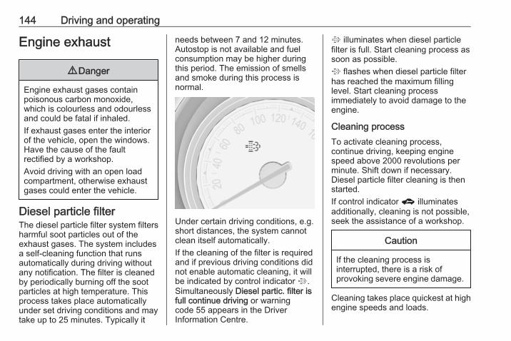
144 Driving and operating
Engine exhaust
9 Danger
Engine exhaust gases containpoisonous carbon monoxide,which is colourless and odourlessand could be fatal if inhaled.If exhaust gases enter the interiorof the vehicle, open the windows.Have the cause of the faultrectified by a workshop.Avoid driving with an open loadcompartment, otherwise exhaustgases could enter the vehicle.
Diesel particle filterThe diesel particle filter system filtersharmful soot particles out of theexhaust gases. The system includesa self-cleaning function that runsautomatically during driving withoutany notification. The filter is cleanedby periodically burning off the sootparticles at high temperature. Thisprocess takes place automaticallyunder set driving conditions and maytake up to 25 minutes. Typically it
needs between 7 and 12 minutes.Autostop is not available and fuelconsumption may be higher duringthis period. The emission of smellsand smoke during this process isnormal.
Under certain driving conditions, e.g.short distances, the system cannotclean itself automatically.If the cleaning of the filter is requiredand if previous driving conditions didnot enable automatic cleaning, it willbe indicated by control indicator %.Simultaneously Diesel partic. filter isfull continue driving or warningcode 55 appears in the DriverInformation Centre.
% illuminates when diesel particlefilter is full. Start cleaning process assoon as possible.% flashes when diesel particle filterhas reached the maximum fillinglevel. Start cleaning processimmediately to avoid damage to theengine.
Cleaning processTo activate cleaning process,continue driving, keeping enginespeed above 2000 revolutions perminute. Shift down if necessary.Diesel particle filter cleaning is thenstarted.If control indicator g illuminatesadditionally, cleaning is not possible,seek the assistance of a workshop.
Caution
If the cleaning process isinterrupted, there is a risk ofprovoking severe engine damage.
Cleaning takes place quickest at highengine speeds and loads.
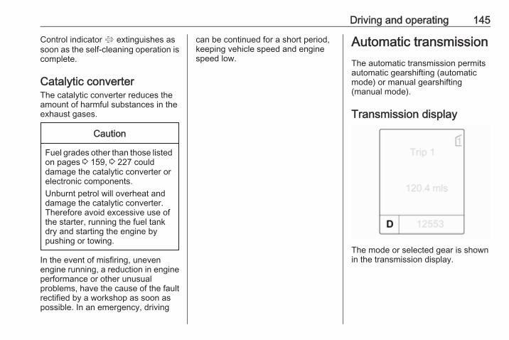
Driving and operating 145
Control indicator % extinguishes assoon as the self-cleaning operation iscomplete.
Catalytic converterThe catalytic converter reduces theamount of harmful substances in theexhaust gases.
Caution
Fuel grades other than those listedon pages 3 159, 3 227 coulddamage the catalytic converter orelectronic components.Unburnt petrol will overheat anddamage the catalytic converter.Therefore avoid excessive use ofthe starter, running the fuel tankdry and starting the engine bypushing or towing.
In the event of misfiring, unevenengine running, a reduction in engineperformance or other unusualproblems, have the cause of the faultrectified by a workshop as soon aspossible. In an emergency, driving
can be continued for a short period,keeping vehicle speed and enginespeed low.
Automatic transmissionThe automatic transmission permitsautomatic gearshifting (automaticmode) or manual gearshifting(manual mode).
Transmission display
The mode or selected gear is shownin the transmission display.

146 Driving and operating
Selector lever
P : park position, wheels are locked,engage only when the vehicle isstationary and the parking brakeis applied
R : reverse gear, engage only whenthe vehicle is stationary
N : neutralD : automatic mode with all gears
The selector lever is locked in P andcan only be moved when the ignitionis on and the brake pedal is applied.
Without brake pedal applied, thecontrol indicator j illuminates.If the selector lever is not in P whenthe ignition is switched off, the controlindicator j and P flash.To engage P or R, press the releasebutton.The engine can only be started withthe lever in position P or N. Whenposition N is selected, press the brakepedal or apply the parking brakebefore starting.Do not accelerate while engaging agear. Never depress the acceleratorpedal and brake pedal at the sametime.
When a gear is engaged, the vehicleslowly begins to creep when thebrake is released.
Engine brakingTo utilise the engine braking effect,select a lower gear in good time whendriving downhill, see manual mode.
Rocking the vehicleRocking the vehicle is onlypermissible if the vehicle is stuck insand, mud or snow. Move the selectorlever between D and R in a repeatpattern. Do not race the engine andavoid sudden acceleration.
ParkingApply the parking brake and engageP.The ignition key can only be removedwhen the selector lever is in positionP.
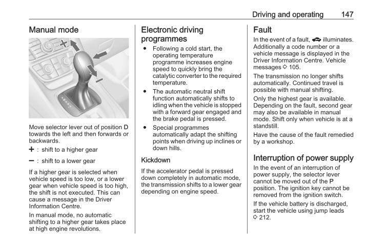
Driving and operating 147
Manual mode
Move selector lever out of position Dtowards the left and then forwards orbackwards.< : shift to a higher gear
] : shift to a lower gear
If a higher gear is selected whenvehicle speed is too low, or a lowergear when vehicle speed is too high,the shift is not executed. This cancause a message in the DriverInformation Centre.In manual mode, no automaticshifting to a higher gear takes placeat high engine revolutions.
Electronic drivingprogrammes● Following a cold start, the
operating temperatureprogramme increases enginespeed to quickly bring thecatalytic converter to the requiredtemperature.
● The automatic neutral shiftfunction automatically shifts toidling when the vehicle is stoppedwith a forward gear engaged andthe brake pedal is pressed.
● Special programmesautomatically adapt the shiftingpoints when driving up inclines ordown hills.
KickdownIf the accelerator pedal is presseddown completely in automatic mode,the transmission shifts to a lower geardepending on engine speed.
FaultIn the event of a fault, g illuminates.Additionally a code number or avehicle message is displayed in theDriver Information Centre. Vehiclemessages 3 105.The transmission no longer shiftsautomatically. Continued travel ispossible with manual shifting.Only the highest gear is available.Depending on the fault, second gearmay also be available in manualmode. Shift only when vehicle is at astandstill.Have the cause of the fault remediedby a workshop.
Interruption of power supplyIn the event of an interruption ofpower supply, the selector levercannot be moved out of the Pposition. The ignition key cannot beremoved from the ignition switch.If the vehicle battery is discharged,start the vehicle using jump leads3 212.

148 Driving and operating
If the vehicle battery is not the causeof the fault, release the selector lever.1. Apply the parking brake.
2. Hold the selector lever trim at themarked position and pull tounlatch at the back.
3. Fold the selector lever trimupwards. Pull to unlatch at thefront.
4. Move the selector lever trim to theleft. Take care that the plug andthe wiring harness at the bottomare not damaged.
5. Insert a screwdriver into theopening as far as it will go andmove the selector lever out of P orN. If P or N is engaged again, theselector lever will be locked inposition again. Have the cause ofthe power supply interruptionremedied by a workshop.
6. Mount the selector lever trim ontothe centre console and refit.
Manual transmission
To engage reverse, depress theclutch pedal and press the releasebutton on the selector lever andengage the gear.If the gear does not engage, set thelever to neutral, release the clutchpedal and depress again; then repeatgear selection.Do not slip the clutch unnecessarily.When operating, depress the clutchpedal completely. Do not use thepedal as a foot rest.

Driving and operating 149
Caution
It is not advisable to drive with thehand resting on the selector lever.
Stop-start system 3 141.
BrakesThe brake system comprises twoindependent brake circuits.If a brake circuit fails, the vehicle canstill be braked using the other brakecircuit. However, braking effect isachieved only when the brake pedalis depressed firmly. Considerablymore force is needed for this. Thebraking distance is extended. Seekthe assistance of a workshop beforecontinuing the journey.When the engine is not running, thesupport of the brake servo unitdisappears once the brake pedal hasbeen depressed once or twice.Braking effect is not reduced, butbraking requires significantly greaterforce. It is especially important to bearthis in mind when being towed.Control indicator R 3 95.
Antilock brake systemAntilock brake system (ABS)prevents the wheels from locking.
ABS starts to regulate brake pressureas soon as a wheel shows a tendencyto lock. The vehicle remainssteerable, even during hard braking.ABS control is made apparentthrough a pulse in the brake pedaland the noise of the regulationprocess.For optimum braking, keep the brakepedal fully depressed throughout thebraking process, despite the fact thatthe pedal is pulsating. Do not reducethe pressure on the pedal.After starting off, the system performsa self-test which may be audible.Control indicator u 3 96.
Adaptive brake lightDuring full braking, all three brakelights flash for the duration of ABScontrol.

150 Driving and operating
Fault
9 Warning
If there is a fault in the ABS, thewheels may be liable to lock dueto braking that is heavier thannormal. The advantages of ABSare no longer available. Duringhard braking, the vehicle can nolonger be steered and mayswerve.
Have the cause of the fault remediedby a workshop.
Parking brakeElectric parking brake
Applying when vehicle is stationary
9 Warning
Pull switch m for approx. onesecond, the electric parking brakeoperates automatically with an
adequate force. For maximumforce, e.g. parking with trailer or oninclines, pull switch m twice.The electric parking brake isapplied when control indicator milluminates 3 96.
The electric parking brake can alwaysbe activated, even if the ignition is off.Do not operate electric parking brakesystem too often with engine notrunning as this will discharge thevehicle battery.Before leaving the vehicle, check theelectric parking brake status.Control indicator m 3 96.
ReleasingSwitch on ignition. Keep brake pedaldepressed and then push switch m.
Drive away functionVehicles with manual transmission:Depressing the clutch pedal and thenslightly releasing the clutch pedal andslightly depressing the acceleratorpedal releases the electric parking
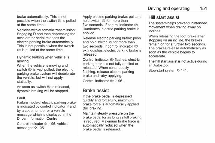
Driving and operating 151
brake automatically. This is notpossible when the switch m is pulledat the same time.Vehicles with automatic transmission:Engaging D and then depressing theaccelerator pedal releases theelectric parking brake automatically.This is not possible when the switchm is pulled at the same time.
Dynamic braking when vehicle ismovingWhen the vehicle is moving andswitch m is kept pulled, the electricparking brake system will deceleratethe vehicle, but will not applystatically.As soon as switch m is released,dynamic braking will be stopped.
FaultFailure mode of electric parking brakeis indicated by control indicator j andby a code number or a vehiclemessage which is displayed in theDriver Information Centre.Control indicator j 3 96, vehiclemessages 3 105.
Apply electric parking brake: pull andhold switch m for more thanfive seconds. If control indicator milluminates, electric parking brake isapplied.Release electric parking brake: pushand hold switch m for more thantwo seconds. If control indicator mextinguishes, electric parking brake isreleased.Control indicator m flashes: electricparking brake is not fully applied orreleased. When continuouslyflashing, release electric parkingbrake and retry applying.Control indicator m 3 96.
Brake assistIf the brake pedal is depressedquickly and forcefully, maximumbrake force is automatically applied(full braking).Maintain steady pressure on thebrake pedal for as long as full brakingis required. Maximum brake force isautomatically reduced when thebrake pedal is released.
Hill start assistThe system helps prevent unintendedmovement when driving away oninclines.When releasing the foot brake afterstopping on an incline, the brakesremain on for a further two seconds.The brakes release automatically assoon as the vehicle begins toaccelerate.The hill start assist is not active duringan Autostop.Stop-start system 3 141.
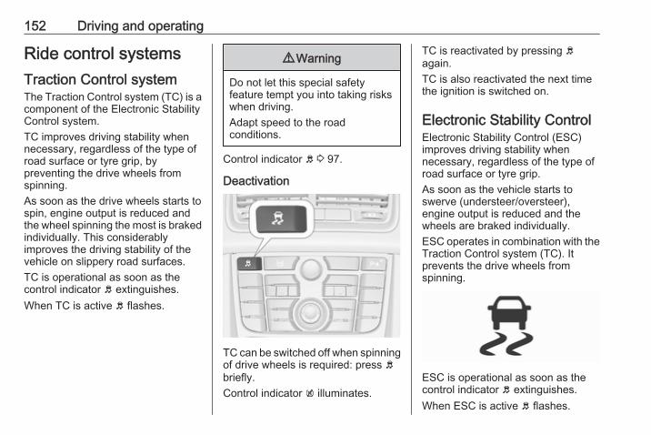
152 Driving and operating
Ride control systemsTraction Control systemThe Traction Control system (TC) is acomponent of the Electronic StabilityControl system.TC improves driving stability whennecessary, regardless of the type ofroad surface or tyre grip, bypreventing the drive wheels fromspinning.As soon as the drive wheels starts tospin, engine output is reduced andthe wheel spinning the most is brakedindividually. This considerablyimproves the driving stability of thevehicle on slippery road surfaces.TC is operational as soon as thecontrol indicator b extinguishes.When TC is active b flashes.
9 Warning
Do not let this special safetyfeature tempt you into taking riskswhen driving.Adapt speed to the roadconditions.
Control indicator b 3 97.
Deactivation
TC can be switched off when spinningof drive wheels is required: press bbriefly.Control indicator k illuminates.
TC is reactivated by pressing bagain.TC is also reactivated the next timethe ignition is switched on.
Electronic Stability ControlElectronic Stability Control (ESC)improves driving stability whennecessary, regardless of the type ofroad surface or tyre grip.As soon as the vehicle starts toswerve (understeer/oversteer),engine output is reduced and thewheels are braked individually.ESC operates in combination with theTraction Control system (TC). Itprevents the drive wheels fromspinning.
ESC is operational as soon as thecontrol indicator b extinguishes.When ESC is active b flashes.

Driving and operating 153
9 Warning
Do not let this special safetyfeature tempt you into taking riskswhen driving.Adapt speed to the roadconditions.
Control indicator b 3 97.
Deactivation
ESC can be deactivated: hold bdepressed for approx. 5 seconds.Control indicator n illuminates.
ESC is reactivated by pressing bagain. If the TC system waspreviously disabled, both TC andESC are reactivated.ESC is also reactivated the next timethe ignition is switched on.
FaultIf there is a fault in the system thecontrol indicator b illuminatescontinuously and a message appearsin the Driver Information Centre. Thesystem is not operational.Have the cause of the fault remediedby a workshop.
Driver assistancesystems
9 Warning
Driver assistance systems aredeveloped to support the driverand not to replace the driver'sattention.The driver accepts fullresponsibility when driving thevehicle.When using driver assistancesystems, always take careregarding the current trafficsituation.
Cruise controlThe cruise control can store andmaintain speeds of approx. 20 to120 mph. Deviations from the storedspeeds may occur when driving uphillor downhill.For safety reasons the cruise controlcannot be activated until the footbrake has been operated once.Activating in first gear is not possible.
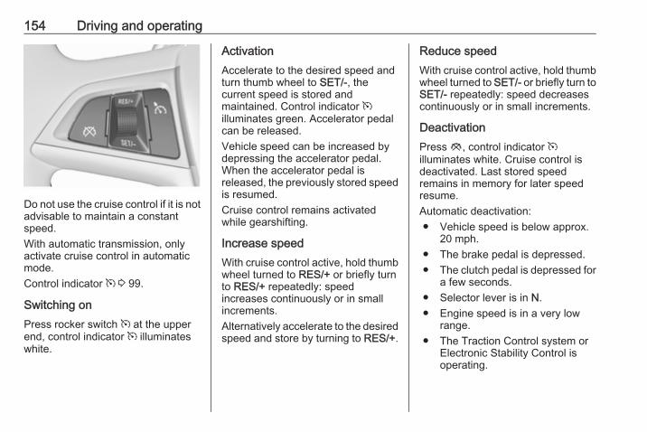
154 Driving and operating
Do not use the cruise control if it is notadvisable to maintain a constantspeed.With automatic transmission, onlyactivate cruise control in automaticmode.Control indicator m 3 99.
Switching onPress rocker switch m at the upperend, control indicator m illuminateswhite.
ActivationAccelerate to the desired speed andturn thumb wheel to SET/-, thecurrent speed is stored andmaintained. Control indicator milluminates green. Accelerator pedalcan be released.Vehicle speed can be increased bydepressing the accelerator pedal.When the accelerator pedal isreleased, the previously stored speedis resumed.Cruise control remains activatedwhile gearshifting.
Increase speedWith cruise control active, hold thumbwheel turned to RES/+ or briefly turnto RES/+ repeatedly: speedincreases continuously or in smallincrements.Alternatively accelerate to the desiredspeed and store by turning to RES/+.
Reduce speedWith cruise control active, hold thumbwheel turned to SET/- or briefly turn toSET/- repeatedly: speed decreasescontinuously or in small increments.
DeactivationPress y, control indicator milluminates white. Cruise control isdeactivated. Last stored speedremains in memory for later speedresume.Automatic deactivation:● Vehicle speed is below approx.
20 mph.● The brake pedal is depressed.● The clutch pedal is depressed for
a few seconds.● Selector lever is in N.● Engine speed is in a very low
range.● The Traction Control system or
Electronic Stability Control isoperating.
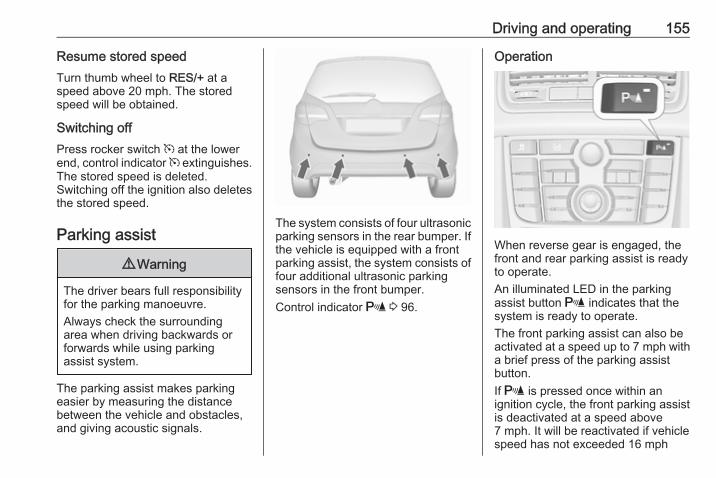
Driving and operating 155
Resume stored speedTurn thumb wheel to RES/+ at aspeed above 20 mph. The storedspeed will be obtained.
Switching offPress rocker switch m at the lowerend, control indicator m extinguishes.The stored speed is deleted.Switching off the ignition also deletesthe stored speed.
Parking assist
9 Warning
The driver bears full responsibilityfor the parking manoeuvre.Always check the surroundingarea when driving backwards orforwards while using parkingassist system.
The parking assist makes parkingeasier by measuring the distancebetween the vehicle and obstacles,and giving acoustic signals.
The system consists of four ultrasonicparking sensors in the rear bumper. Ifthe vehicle is equipped with a frontparking assist, the system consists offour additional ultrasonic parkingsensors in the front bumper.Control indicator r 3 96.
Operation
When reverse gear is engaged, thefront and rear parking assist is readyto operate.An illuminated LED in the parkingassist button r indicates that thesystem is ready to operate.The front parking assist can also beactivated at a speed up to 7 mph witha brief press of the parking assistbutton.If r is pressed once within anignition cycle, the front parking assistis deactivated at a speed above7 mph. It will be reactivated if vehiclespeed has not exceeded 16 mph

156 Driving and operating
beforehand. If vehicle speed hasexceeded 16 mph beforehand, frontparking assist remains deactivatedwhen speed drops below 7 mph.When the system is deactivated, theLED in the button extinguishes andPark Assist Off pops-up in the DriverInformation Centre.The system is deactivatedautomatically when exceeding16 mph.If the vehicle is equipped with rearparking assist only, the systemautomatically switches off whenreverse gear is disengaged. Manualdeactivation is also possible bypressing r.
IndicationAn obstacle is indicated by a buzzingsound. The interval between thesounds becomes shorter as thevehicle gets closer to the obstacle.When the distance is less than30 cm, the buzzing is continuous.
FaultIn the event of a fault in the system,r illuminates or a vehicle messageis displayed in the Driver InformationCentre.Additionally, r illuminates or avehicle message is displayed in theDriver Information Centre if amalfunction of the system due totemporary conditions like snowcovered sensors is detected.Vehicle messages 3 105.
Important hints for using theparking assist systems
9 Warning
Under certain circumstances,various reflective surfaces onobjects or clothing as well asexternal noise sources may causethe system to fail to detectobstacles.Special attention must be paid tolow obstacles which can damagethe lower part of the bumper. Ifsuch obstacles leave the detection
area of the sensors duringapproach of the vehicle, acontinuous warning tone willsound.
Caution
Performance of the sensors canbe reduced when sensors arecovered, e.g. by ice or snow.Performance of the parking assistsystems can be reduced due toheavy loading.Special conditions apply if thereare taller vehicles involved (e.g.off-road vehicles, mini vans,vans). Object identification in theupper part of these vehiclescannot be guaranteed.Objects with a very small reflectioncross-section, e.g. objects ofnarrow size or soft materials, maynot be detected by the system.The parking assist system will notavoid a collision with objects whichare out of the detection range ofthe sensors.
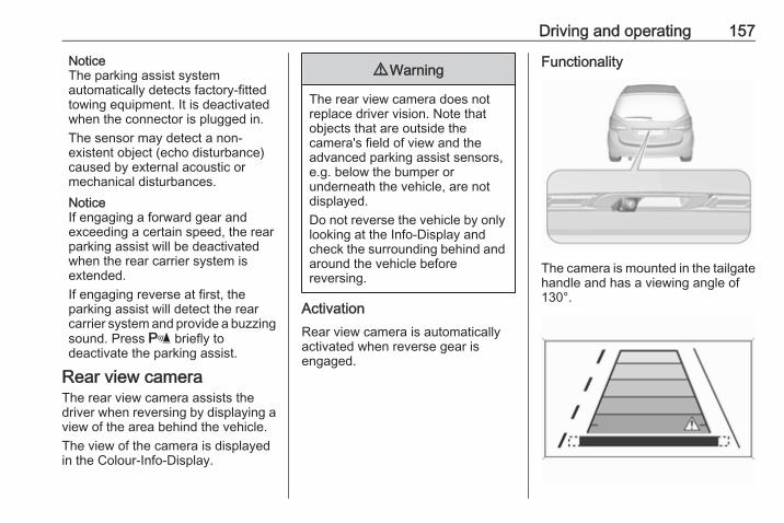
Driving and operating 157
NoticeThe parking assist systemautomatically detects factory-fittedtowing equipment. It is deactivatedwhen the connector is plugged in.The sensor may detect a non-existent object (echo disturbance)caused by external acoustic ormechanical disturbances.NoticeIf engaging a forward gear andexceeding a certain speed, the rearparking assist will be deactivatedwhen the rear carrier system isextended.If engaging reverse at first, theparking assist will detect the rearcarrier system and provide a buzzingsound. Press r briefly todeactivate the parking assist.
Rear view cameraThe rear view camera assists thedriver when reversing by displaying aview of the area behind the vehicle.The view of the camera is displayedin the Colour-Info-Display.
9 Warning
The rear view camera does notreplace driver vision. Note thatobjects that are outside thecamera's field of view and theadvanced parking assist sensors,e.g. below the bumper orunderneath the vehicle, are notdisplayed.Do not reverse the vehicle by onlylooking at the Info-Display andcheck the surrounding behind andaround the vehicle beforereversing.
ActivationRear view camera is automaticallyactivated when reverse gear isengaged.
Functionality
The camera is mounted in the tailgatehandle and has a viewing angle of130°.
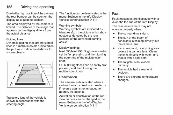
158 Driving and operating
Due to the high position of the camerathe rear bumper can be seen on thedisplay as a guide to position.The area displayed by the camera islimited. The distance of the image thatappears on the display differs fromthe actual distance.
Guiding linesDynamic guiding lines are horizontallines in 1 metre intervals projected onthe picture to define the distance toshown objects.
Trajectory lane of the vehicle isshown in accordance with thesteering angle.
The function can be deactivated in themenu Settings in the Info-Display.Vehicle personalisation 3 111.
Warning symbolsWarning symbols are indicated astriangles 9 on the picture which showobstacles detected by the rearsensors of the advanced parkingassist.
Display settingsNavi 650/Navi 950: Brightness can beset by first pressing and then turningthe outer ring of the multifunctionknob.CD 600: Brightness can be set by firstpressing and then turning themultifunction knob.
DeactivationThe camera is deactivated when acertain forward speed is exceeded orif reverse gear is not engaged forapprox. 10 seconds.Activation or deactivation of the rearview camera can be changed in themenu Settings in the Info-Display.Vehicle personalisation 3 111.
FaultFault messages are displayed with a9 on the top line of the Info-Display.The rear view camera may notoperate properly when:● The surrounding is dark.● The sun or the beam of
headlights is shining directly intothe camera lens.
● Ice, snow, mud, or anything elsecovers the camera lens. Cleanthe lens, rinse it with water, andwipe it with a soft cloth.
● The tailgate is not closedcorrectly.
● The vehicle had a rear endaccident.
● There are extreme temperaturechanges.
Driving and operating 159
FuelFuel for petrol enginesOnly use unleaded fuel that complieswith European standard EN 228 orE DIN 51626-1 or equivalent.The engine is capable of running withfuel that contains up to 10% ethanol(e.g. named E10).Use fuel with the recommendedoctane rating. The engine specificrequirements are given in the enginedata overview 3 227. A countryspecific label at the fuel filler flap cansupersede the requirement.
Caution
Do not use fuel or fuel additivesthat contain metallic compoundssuch as manganese-basedadditives. This may cause enginedamage.
Caution
Use of fuel that does not comply toEN 228 or E DIN 51626-1 orequivalent can lead to deposits orengine damage.
Caution
Use of fuel with too low an octanerating could lead to uncontrolledcombustion and engine damage.
Fuel for diesel enginesOnly use diesel fuel that complieswith EN 590.In countries outside the EuropeanUnion use Euro-Diesel fuel with asulfur concentration below 50 ppm.
Caution
Use of fuel that does not comply toEN 590 or similar can lead toengine powerloss, increased wearor engine damage.
Do not use marine diesel oils, heatingoils, Aquazole and similar diesel-water emulsions. Diesel fuels mustnot be diluted with fuels for petrolengines.
Fuel for liquid gas operationLiquid gas is known as LPG(Liquefied Petroleum Gas) or underits French name GPL (Gaz de PétroleLiquéfié). LPG is also known asAutogas.LPG consists mainly of propane andbutane. The octane rating is between105 and 115, depending on thebutane proportion. LPG is storedliquid at around five to ten barpressure.The boiling point depends on thepressure and mixing ratio. At ambientpressure, it is between -42 °C (purepropane) and -0.5 °C (pure butane).
Caution
The system works at an ambienttemperature of approx. -8 °C to100 °C.
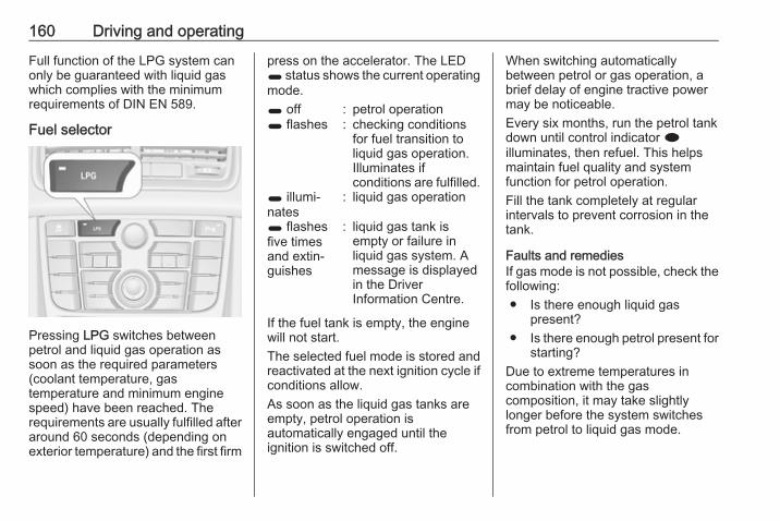
160 Driving and operating
Full function of the LPG system canonly be guaranteed with liquid gaswhich complies with the minimumrequirements of DIN EN 589.
Fuel selector
Pressing LPG switches betweenpetrol and liquid gas operation assoon as the required parameters(coolant temperature, gastemperature and minimum enginespeed) have been reached. Therequirements are usually fulfilled afteraround 60 seconds (depending onexterior temperature) and the first firm
press on the accelerator. The LED1 status shows the current operatingmode.1 off : petrol operation1 flashes : checking conditions
for fuel transition toliquid gas operation.Illuminates ifconditions are fulfilled.
1 illumi‐nates
: liquid gas operation
1 flashesfive timesand extin‐guishes
: liquid gas tank isempty or failure inliquid gas system. Amessage is displayedin the DriverInformation Centre.
If the fuel tank is empty, the enginewill not start.The selected fuel mode is stored andreactivated at the next ignition cycle ifconditions allow.As soon as the liquid gas tanks areempty, petrol operation isautomatically engaged until theignition is switched off.
When switching automaticallybetween petrol or gas operation, abrief delay of engine tractive powermay be noticeable.Every six months, run the petrol tankdown until control indicator iilluminates, then refuel. This helpsmaintain fuel quality and systemfunction for petrol operation.Fill the tank completely at regularintervals to prevent corrosion in thetank.
Faults and remediesIf gas mode is not possible, check thefollowing:● Is there enough liquid gas
present?● Is there enough petrol present for
starting?Due to extreme temperatures incombination with the gascomposition, it may take slightlylonger before the system switchesfrom petrol to liquid gas mode.

Driving and operating 161
In extreme situations, the system mayalso switch back to petrol mode if theminimum requirements are notfulfilled. If conditions allow, it might bepossible to manually switch back toliquid gas operation.Seek the assistance of a workshop inthe event of all other faults.
Caution
Repairs and adjustments may onlybe made by trained specialists inorder to maintain the safety andwarranty on the LPG system.
Liquid gas is given a particular odour(odorised) so that any leaks can bedetected easily.
9 Warning
If you smell gas in the vehicle or inthe immediate vicinity, switch topetrol mode immediately. Nosmoking. No naked flames orignition sources.
If possible, close the manual shut-offvalve on the multivalve. Themultivalve is located on the liquid gastank in the load compartment,underneath the rear floor cover.
Turn the thumb wheel clockwise.If no further gas odour is perceptiblewhen the manual shut-off valve isclosed, the vehicle can be used inpetrol mode. If the gas odour persists,do not start the engine. Have thecause of the fault remedied by aworkshop.When using underground car parks,follow the instructions of the operatorand local laws.
NoticeIn the event of an accident, switch offthe ignition and lights. Close themanual shut-off valve on multivalve.
Refuelling
9 Danger
Before refuelling, switch offignition and any external heaterswith combustion chambers.Follow the operating and safetyinstructions of the filling stationwhen refuelling.
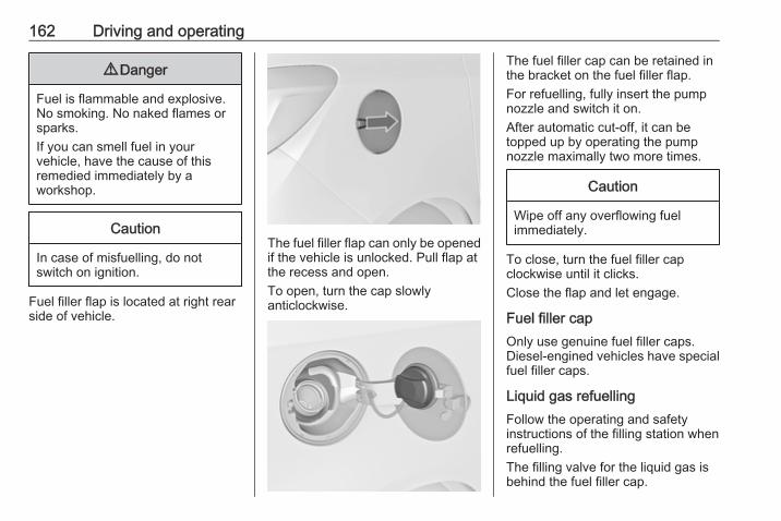
162 Driving and operating
9 Danger
Fuel is flammable and explosive.No smoking. No naked flames orsparks.If you can smell fuel in yourvehicle, have the cause of thisremedied immediately by aworkshop.
Caution
In case of misfuelling, do notswitch on ignition.
Fuel filler flap is located at right rearside of vehicle.
The fuel filler flap can only be openedif the vehicle is unlocked. Pull flap atthe recess and open.To open, turn the cap slowlyanticlockwise.
The fuel filler cap can be retained inthe bracket on the fuel filler flap.For refuelling, fully insert the pumpnozzle and switch it on.After automatic cut-off, it can betopped up by operating the pumpnozzle maximally two more times.
Caution
Wipe off any overflowing fuelimmediately.
To close, turn the fuel filler capclockwise until it clicks.Close the flap and let engage.
Fuel filler capOnly use genuine fuel filler caps.Diesel-engined vehicles have specialfuel filler caps.
Liquid gas refuellingFollow the operating and safetyinstructions of the filling station whenrefuelling.The filling valve for the liquid gas isbehind the fuel filler cap.
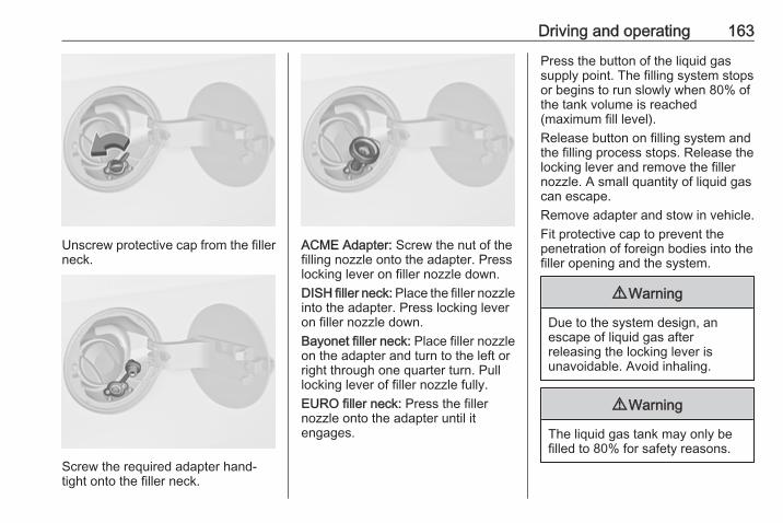
Driving and operating 163
Unscrew protective cap from the fillerneck.
Screw the required adapter hand-tight onto the filler neck.
ACME Adapter: Screw the nut of thefilling nozzle onto the adapter. Presslocking lever on filler nozzle down.DISH filler neck: Place the filler nozzleinto the adapter. Press locking leveron filler nozzle down.Bayonet filler neck: Place filler nozzleon the adapter and turn to the left orright through one quarter turn. Pulllocking lever of filler nozzle fully.EURO filler neck: Press the fillernozzle onto the adapter until itengages.
Press the button of the liquid gassupply point. The filling system stopsor begins to run slowly when 80% ofthe tank volume is reached(maximum fill level).Release button on filling system andthe filling process stops. Release thelocking lever and remove the fillernozzle. A small quantity of liquid gascan escape.Remove adapter and stow in vehicle.Fit protective cap to prevent thepenetration of foreign bodies into thefiller opening and the system.
9 Warning
Due to the system design, anescape of liquid gas afterreleasing the locking lever isunavoidable. Avoid inhaling.
9 Warning
The liquid gas tank may only befilled to 80% for safety reasons.
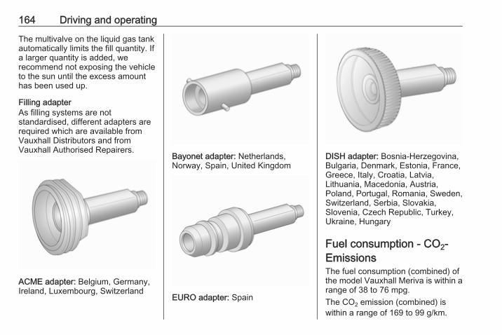
164 Driving and operating
The multivalve on the liquid gas tankautomatically limits the fill quantity. Ifa larger quantity is added, werecommend not exposing the vehicleto the sun until the excess amounthas been used up.
Filling adapterAs filling systems are notstandardised, different adapters arerequired which are available fromVauxhall Distributors and fromVauxhall Authorised Repairers.
ACME adapter: Belgium, Germany,Ireland, Luxembourg, Switzerland
Bayonet adapter: Netherlands,Norway, Spain, United Kingdom
EURO adapter: Spain
DISH adapter: Bosnia-Herzegovina,Bulgaria, Denmark, Estonia, France,Greece, Italy, Croatia, Latvia,Lithuania, Macedonia, Austria,Poland, Portugal, Romania, Sweden,Switzerland, Serbia, Slovakia,Slovenia, Czech Republic, Turkey,Ukraine, Hungary
Fuel consumption - CO2-Emissions The fuel consumption (combined) ofthe model Vauxhall Meriva is within arange of 38 to 76 mpg.The CO2 emission (combined) iswithin a range of 169 to 99 g/km.
Driving and operating 165
For the values specific for yourvehicle, refer to the EEC Certificate ofConformity provided with your vehicleor other national registrationdocuments.
General informationThe official fuel consumption andspecific CO2 emission figures quotedrelate to the EU base model withstandard equipment.Fuel consumption data and CO2emission data are determinedaccording to regulation R (EC) No.715/2007 (in the version respectivelyapplicable), taking into considerationthe vehicle weight in running order, asspecified by the regulation.The figures are provided only for thepurpose of comparison betweendifferent vehicle variants and mustnot be taken as a guarantee for theactual fuel consumption of aparticular vehicle. Additionalequipment may result in slightlyhigher results than the statedconsumption and CO2 figures.
Furthermore, fuel consumption isdependent on personal driving styleas well as road and traffic conditions.
Trailer hitchGeneral informationOnly use towing equipment that hasbeen approved for your vehicle.Entrust retrofitting of towingequipment to a workshop. It may benecessary to make changes thataffect the cooling system, heatshields or other equipment.The bulb outage detection function fortrailer brake light cannot detect apartial bulb outage, e.g. in case of fourtimes five watt bulbs, the function onlydetects lamp outage when only asingle five Watt lamp remains or noneremain.Fitting of towing equipment couldcover the opening of the towing eye.If this is the case use the coupling ballbar for towing. Always keep thecoupling ball bar in the vehicle whennot in use.

166 Driving and operating
Driving characteristics andtowing tipsBefore attaching a trailer, lubricatethe coupling ball. However, do not doso if a stabiliser, which acts on thecoupling ball, is being used to reducesnaking movements.For trailers with low driving stabilityand caravan trailers with a permittedgross vehicle weight of more than1100 kg the use of a stabiliser isstrongly recommended when drivingabove 50 mph.If the trailer starts snaking, drive moreslowly, do not attempt to correct thesteering and brake sharply ifnecessary.When driving downhill, drive in thesame gear as if driving uphill anddrive at a similar speed.Adjust tyre pressure to the valuespecified for full load 3 234.
Trailer towingTrailer loads
9 Warning
Vehicles with engine A13DTE:Use of towing equipment ispermissible for attachingcompatible bicycle carriers only.Do not use towing equipment fortrailer towing.
The permissible trailer loads arevehicle and engine-dependentmaximum values which must not beexceeded. The actual trailer load isthe difference between the actualgross weight of the trailer and theactual coupling socket load with thetrailer coupled.The permissible trailer loads arespecified in the vehicle documents. Ingeneral, they are valid for gradientsup to max. 12%.The permitted trailer load applies upto the specified incline and up to analtitude of 1000 metres above sealevel. Since engine power decreases
as altitude increases due to the airbecoming thinner, therefore reducingclimbing ability, the permissible grosstrain weight also decreases by 10%for every 1000 metres of additionalaltitude. The gross train weight doesnot have to be reduced when drivingon roads with slight inclines (less than8%, e.g. motorways).The permissible gross train weightmust not be exceeded. This weight isspecified on the identification plate3 223.
Vertical coupling loadThe vertical coupling load is the loadexerted by the trailer on the couplingball. It can be varied by changing theweight distribution when loading thetrailer.The maximum permissible verticalcoupling load (75 kg) is specified onthe towing equipment identificationplate and in the vehicle documents.Always aim for the maximum load,especially in the case of heavytrailers. The vertical coupling loadshould never fall below 25 kg.
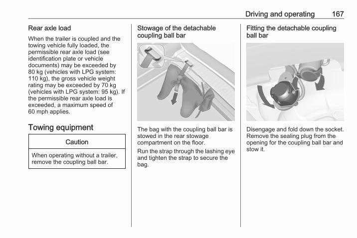
Driving and operating 167
Rear axle loadWhen the trailer is coupled and thetowing vehicle fully loaded, thepermissible rear axle load (seeidentification plate or vehicledocuments) may be exceeded by80 kg (vehicles with LPG system:110 kg), the gross vehicle weightrating may be exceeded by 70 kg(vehicles with LPG system: 95 kg). Ifthe permissible rear axle load isexceeded, a maximum speed of60 mph applies.
Towing equipment
Caution
When operating without a trailer,remove the coupling ball bar.
Stowage of the detachablecoupling ball bar
The bag with the coupling ball bar isstowed in the rear stowagecompartment on the floor.Run the strap through the lashing eyeand tighten the strap to secure thebag.
Fitting the detachable couplingball bar
Disengage and fold down the socket.Remove the sealing plug from theopening for the coupling ball bar andstow it.
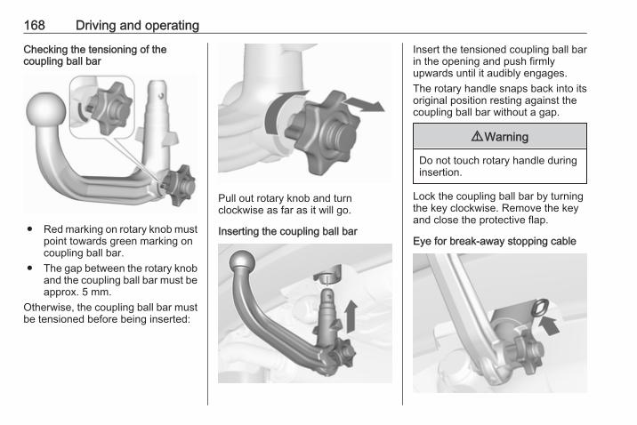
168 Driving and operating
Checking the tensioning of thecoupling ball bar
● Red marking on rotary knob mustpoint towards green marking oncoupling ball bar.
● The gap between the rotary knoband the coupling ball bar must beapprox. 5 mm.
Otherwise, the coupling ball bar mustbe tensioned before being inserted:
Pull out rotary knob and turnclockwise as far as it will go.
Inserting the coupling ball bar
Insert the tensioned coupling ball barin the opening and push firmlyupwards until it audibly engages.The rotary handle snaps back into itsoriginal position resting against thecoupling ball bar without a gap.
9 Warning
Do not touch rotary handle duringinsertion.
Lock the coupling ball bar by turningthe key clockwise. Remove the keyand close the protective flap.
Eye for break-away stopping cable
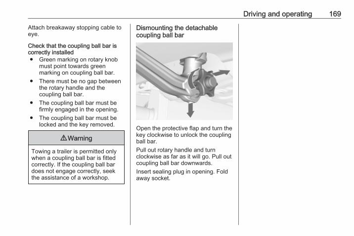
Driving and operating 169
Attach breakaway stopping cable toeye.
Check that the coupling ball bar iscorrectly installed● Green marking on rotary knob
must point towards greenmarking on coupling ball bar.
● There must be no gap betweenthe rotary handle and thecoupling ball bar.
● The coupling ball bar must befirmly engaged in the opening.
● The coupling ball bar must belocked and the key removed.
9 Warning
Towing a trailer is permitted onlywhen a coupling ball bar is fittedcorrectly. If the coupling ball bardoes not engage correctly, seekthe assistance of a workshop.
Dismounting the detachablecoupling ball bar
Open the protective flap and turn thekey clockwise to unlock the couplingball bar.Pull out rotary handle and turnclockwise as far as it will go. Pull outcoupling ball bar downwards.Insert sealing plug in opening. Foldaway socket.
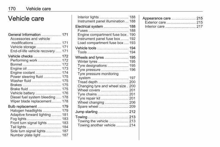
170 Vehicle care
Vehicle care
General Information ................... 171Accessories and vehiclemodifications .......................... 171
Vehicle storage ........................ 171End-of-life vehicle recovery ..... 171
Vehicle checks ........................... 172Performing work ...................... 172Bonnet ..................................... 172Engine oil ................................. 173Engine coolant ......................... 174Power steering fluid ................. 175Washer fluid ............................ 175Brakes ..................................... 175Brake fluid ............................... 175Vehicle battery ......................... 176Diesel fuel system bleeding ..... 178Wiper blade replacement ........ 178
Bulb replacement ....................... 179Halogen headlights .................. 179Adaptive forward lighting ......... 181Fog lights ................................. 183Front turn signal lights ............. 183Tail lights ................................. 184Side turn signal lights .............. 187Number plate light ................... 187
Interior lights ............................ 188Instrument panel illumination ... 188
Electrical system ........................ 188Fuses ....................................... 188Engine compartment fuse box . 190Instrument panel fuse box ....... 192Load compartment fuse box .... 193
Vehicle tools .............................. 194Tools ........................................ 194
Wheels and tyres ....................... 195Winter tyres ............................. 195Tyre designations .................... 195Tyre pressure .......................... 196Tyre pressure monitoringsystem .................................... 197
Tread depth ............................. 200Changing tyre and wheel size . 200Wheel covers ........................... 201Tyre chains .............................. 201Tyre repair kit .......................... 201Wheel changing ....................... 206Spare wheel ............................ 209
Jump starting ............................. 212Towing ....................................... 213
Towing the vehicle ................... 213Towing another vehicle ........... 214
Appearance care ....................... 215Exterior care ............................ 215Interior care ............................. 217
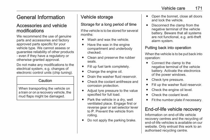
Vehicle care 171
General InformationAccessories and vehiclemodificationsWe recommend the use of genuineparts and accessories and factoryapproved parts specific for yourvehicle type. We cannot assess orguarantee reliability of other products- even if they have a regulatory orotherwise granted approval.Do not make any modifications to theelectrical system, e.g. changes ofelectronic control units (chip tuning).
Caution
When transporting the vehicle ona train or on a recovery vehicle, themud flaps might be damaged.
Vehicle storageStorage for a long period of timeIf the vehicle is to be stored for severalmonths:● Wash and wax the vehicle.● Have the wax in the engine
compartment and underbodychecked.
● Clean and preserve the rubberseals.
● Fill up fuel tank completely.● Change the engine oil.● Drain the washer fluid reservoir.● Check the coolant antifreeze and
corrosion protection.● Adjust tyre pressure to the value
specified for full load.● Park the vehicle in a dry, well
ventilated place. Engage first orreverse gear or set selector leverto P. Prevent the vehicle fromrolling.
● Do not apply the parking brake.
● Open the bonnet, close all doorsand lock the vehicle.
● Disconnect the clamp from thenegative terminal of the vehiclebattery. Beware that all systemsare not functional, e.g. anti-theftalarm system.
Putting back into operationWhen the vehicle is to be put back intooperation:● Connect the clamp to the
negative terminal of the vehiclebattery. Activate the electronicsof the power windows.
● Check tyre pressure.● Fill up the washer fluid reservoir.● Check the engine oil level.● Check the coolant level.● Fit the number plate if necessary.
End-of-life vehicle recoveryInformation on end-of-life vehiclerecovery centres and the recycling ofend-of-life vehicles is available on ourwebsite. Only entrust this work to anauthorised recycling centre.
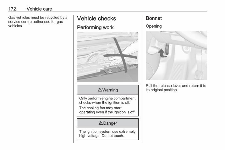
172 Vehicle care
Gas vehicles must be recycled by aservice centre authorised for gasvehicles.
Vehicle checksPerforming work
9 Warning
Only perform engine compartmentchecks when the ignition is off.The cooling fan may startoperating even if the ignition is off.
9 Danger
The ignition system use extremelyhigh voltage. Do not touch.
BonnetOpening
Pull the release lever and return it toits original position.
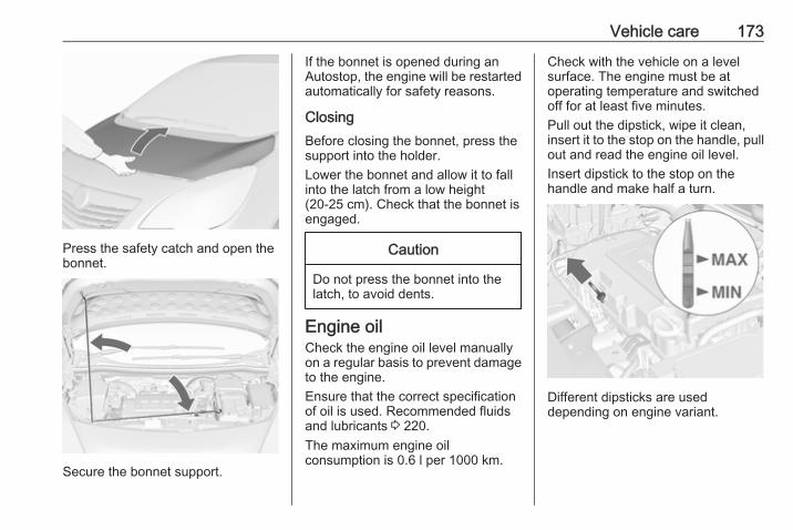
Vehicle care 173
Press the safety catch and open thebonnet.
Secure the bonnet support.
If the bonnet is opened during anAutostop, the engine will be restartedautomatically for safety reasons.
ClosingBefore closing the bonnet, press thesupport into the holder.Lower the bonnet and allow it to fallinto the latch from a low height(20-25 cm). Check that the bonnet isengaged.
Caution
Do not press the bonnet into thelatch, to avoid dents.
Engine oilCheck the engine oil level manuallyon a regular basis to prevent damageto the engine.Ensure that the correct specificationof oil is used. Recommended fluidsand lubricants 3 220.The maximum engine oilconsumption is 0.6 l per 1000 km.
Check with the vehicle on a levelsurface. The engine must be atoperating temperature and switchedoff for at least five minutes.Pull out the dipstick, wipe it clean,insert it to the stop on the handle, pullout and read the engine oil level.Insert dipstick to the stop on thehandle and make half a turn.
Different dipsticks are useddepending on engine variant.
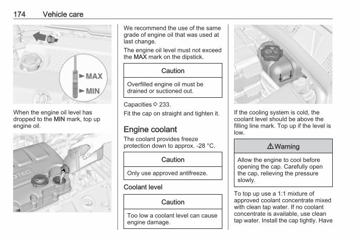
174 Vehicle care
When the engine oil level hasdropped to the MIN mark, top upengine oil.
We recommend the use of the samegrade of engine oil that was used atlast change.The engine oil level must not exceedthe MAX mark on the dipstick.
Caution
Overfilled engine oil must bedrained or suctioned out.
Capacities 3 233.Fit the cap on straight and tighten it.
Engine coolantThe coolant provides freezeprotection down to approx. -28 °C.
Caution
Only use approved antifreeze.
Coolant level
Caution
Too low a coolant level can causeengine damage.
If the cooling system is cold, thecoolant level should be above thefilling line mark. Top up if the level islow.
9 Warning
Allow the engine to cool beforeopening the cap. Carefully openthe cap, relieving the pressureslowly.
To top up use a 1:1 mixture ofapproved coolant concentrate mixedwith clean tap water. If no coolantconcentrate is available, use cleantap water. Install the cap tightly. Have
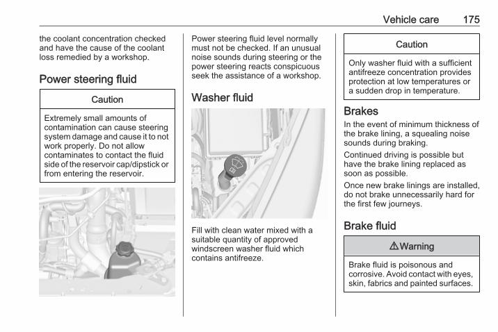
Vehicle care 175
the coolant concentration checkedand have the cause of the coolantloss remedied by a workshop.
Power steering fluid
Caution
Extremely small amounts ofcontamination can cause steeringsystem damage and cause it to notwork properly. Do not allowcontaminates to contact the fluidside of the reservoir cap/dipstick orfrom entering the reservoir.
Power steering fluid level normallymust not be checked. If an unusualnoise sounds during steering or thepower steering reacts conspicuousseek the assistance of a workshop.
Washer fluid
Fill with clean water mixed with asuitable quantity of approvedwindscreen washer fluid whichcontains antifreeze.
Caution
Only washer fluid with a sufficientantifreeze concentration providesprotection at low temperatures ora sudden drop in temperature.
BrakesIn the event of minimum thickness ofthe brake lining, a squealing noisesounds during braking.Continued driving is possible buthave the brake lining replaced assoon as possible.Once new brake linings are installed,do not brake unnecessarily hard forthe first few journeys.
Brake fluid
9 Warning
Brake fluid is poisonous andcorrosive. Avoid contact with eyes,skin, fabrics and painted surfaces.

176 Vehicle care
The brake fluid level must be betweenthe MIN and the MAX marks.When topping up, ensure maximumcleanliness as contamination of thebrake fluid can lead to brake systemmalfunctions. Have the cause of theloss of brake fluid remedied by aworkshop.Only use high-performance brakefluid approved for the vehicle.Brake and clutch fluid 3 220.
Vehicle batteryThe vehicle battery is maintenance-free provided that the driving profileallows sufficient charging of the
battery. Short-distance-driving andfrequent engine starts can dischargethe battery. Avoid the use ofunnecessary electrical consumers.
Batteries do not belong in householdwaste. They must be disposed of atan appropriate recycling collectionpoint.Laying up the vehicle for more thanfour weeks can lead to batterydischarge. Disconnect the clamp fromthe negative terminal of the vehiclebattery.Ensure the ignition is switched offbefore connecting or disconnectingthe vehicle battery.The anti-theft alarm siren must bedeactivated as follows: Switch theignition on then off, disconnect thevehicle's battery within 15 seconds.Vehicle battery discharge protection3 127.
Replacing the vehicle batteryNoticeAny deviation from the instructionsgiven in this paragraph may lead toa temporary deactivation of the stop-start system.
When the vehicle battery is beingreplaced, please ensure that thereare no open ventilation holes in thevicinity of the positive terminal. If aventilation hole is open in this area, itmust be closed off with a dummy cap,and the ventilation in the vicinity of thenegative terminal must be opened.Only use vehicle batteries that allowthe fuse box to be mounted above thevehicle battery.In vehicles with an AGM (AbsorptiveGlass Mat) battery, make sure tohave the battery replaced withanother AGM battery.
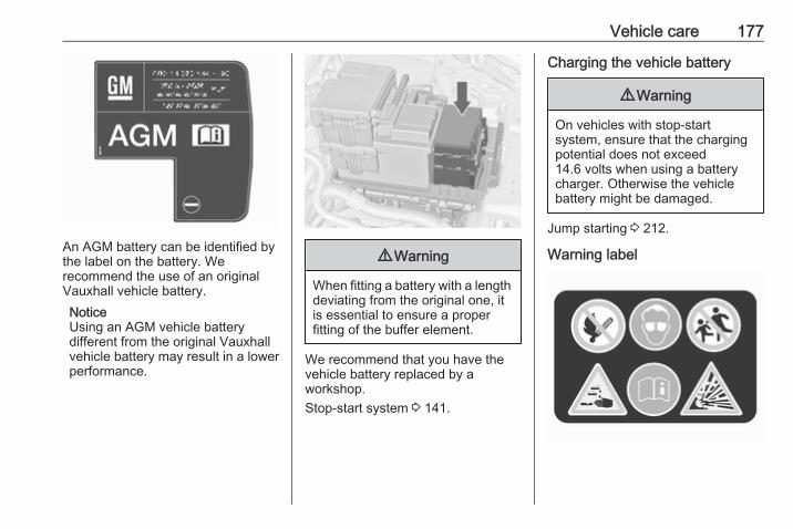
Vehicle care 177
An AGM battery can be identified bythe label on the battery. Werecommend the use of an originalVauxhall vehicle battery.NoticeUsing an AGM vehicle batterydifferent from the original Vauxhallvehicle battery may result in a lowerperformance.
9 Warning
When fitting a battery with a lengthdeviating from the original one, itis essential to ensure a properfitting of the buffer element.
We recommend that you have thevehicle battery replaced by aworkshop.Stop-start system 3 141.
Charging the vehicle battery
9 Warning
On vehicles with stop-startsystem, ensure that the chargingpotential does not exceed14.6 volts when using a batterycharger. Otherwise the vehiclebattery might be damaged.
Jump starting 3 212.
Warning label
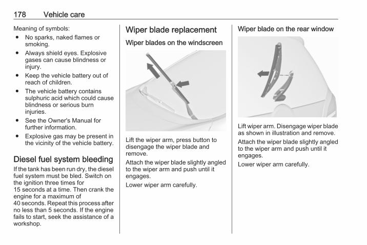
178 Vehicle care
Meaning of symbols:● No sparks, naked flames or
smoking.● Always shield eyes. Explosive
gases can cause blindness orinjury.
● Keep the vehicle battery out ofreach of children.
● The vehicle battery containssulphuric acid which could causeblindness or serious burninjuries.
● See the Owner's Manual forfurther information.
● Explosive gas may be present inthe vicinity of the vehicle battery.
Diesel fuel system bleedingIf the tank has been run dry, the dieselfuel system must be bled. Switch onthe ignition three times for15 seconds at a time. Then crank theengine for a maximum of40 seconds. Repeat this process afterno less than 5 seconds. If the enginefails to start, seek the assistance of aworkshop.
Wiper blade replacementWiper blades on the windscreen
Lift the wiper arm, press button todisengage the wiper blade andremove.Attach the wiper blade slightly angledto the wiper arm and push until itengages.Lower wiper arm carefully.
Wiper blade on the rear window
Lift wiper arm. Disengage wiper bladeas shown in illustration and remove.Attach the wiper blade slightly angledto the wiper arm and push until itengages.Lower wiper arm carefully.
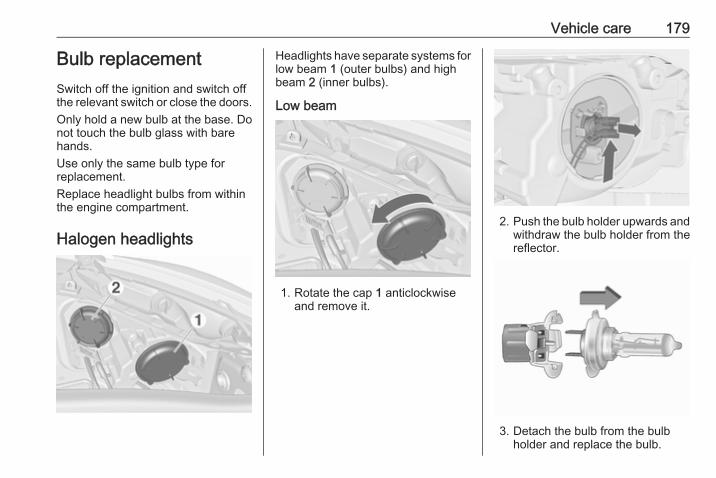
Vehicle care 179
Bulb replacementSwitch off the ignition and switch offthe relevant switch or close the doors.Only hold a new bulb at the base. Donot touch the bulb glass with barehands.Use only the same bulb type forreplacement.Replace headlight bulbs from withinthe engine compartment.
Halogen headlights
Headlights have separate systems forlow beam 1 (outer bulbs) and highbeam 2 (inner bulbs).
Low beam
1. Rotate the cap 1 anticlockwiseand remove it.
2. Push the bulb holder upwards andwithdraw the bulb holder from thereflector.
3. Detach the bulb from the bulbholder and replace the bulb.
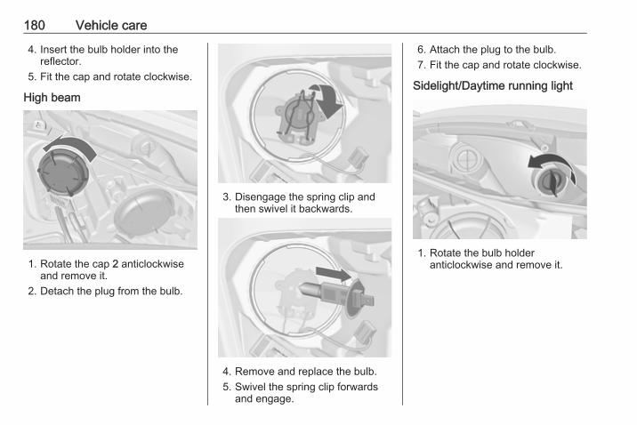
180 Vehicle care
4. Insert the bulb holder into thereflector.
5. Fit the cap and rotate clockwise.
High beam
1. Rotate the cap 2 anticlockwiseand remove it.
2. Detach the plug from the bulb.
3. Disengage the spring clip andthen swivel it backwards.
4. Remove and replace the bulb.5. Swivel the spring clip forwards
and engage.
6. Attach the plug to the bulb.7. Fit the cap and rotate clockwise.
Sidelight/Daytime running light
1. Rotate the bulb holderanticlockwise and remove it.

Vehicle care 181
2. Detach bulb from the bulb holderand replace it.
3. Insert the bulb holder into thereflector and rotate clockwise.
Sidelight/Daytime running lightwith LEDsOn another version sidelight anddaytime running lights are designedas LEDs. In case of defective haveLEDs replaced by a workshop.
Adaptive forward lighting
Headlights have separate systems forlow beam and high beam 1 (outerbulbs) and cornering light 2 (innerbulbs).
Low beam/High beam
1. Rotate the cap 1 anticlockwiseand remove it.

182 Vehicle care
2. Rotate the bulb holder clockwiseto disengage. Withdraw the bulbholder from the reflector.
3. Disengage the bulb holder fromthe plug connector by pressingthe retaining lug.
4. Replace the bulb and connectbulb holder with the plugconnector.
5. Insert the bulb holder, engagingthe two lugs into the reflector androtate anticlockwise to secure.
6. Fit the cap and rotate clockwise.
Cornering light
1. Rotate protective cover 2anticlockwise and remove.
2. Rotate the bulb holderanticlockwise to disengage.Withdraw the bulb holder from thereflector.
3. Disengage the bulb holder fromthe plug connector by pressingthe retaining lugs.
4. Replace the bulb and connectbulb holder with the plugconnector.
5. Insert the bulb holder, engagingthe two lugs into the reflector androtate clockwise to secure.
6. Fit the cap and rotate clockwise.

Vehicle care 183
Sidelight/Daytime running lightSidelight and daytime running lightsare designed as LEDs. In case offailure, have LEDs replaced by aworkshop.
Fog lights
The bulbs are accessible from theunderside of the vehicle.
1. Turn the bulb holder anticlockwiseand remove it from the reflector.
2. Disengage the bulb holder fromthe plug connector by pressingthe retaining lug.
3. Remove and replace the bulbholder with bulb.
4. Attach the plug connector.5. Insert the bulb holder into the
reflector.6. Turn the bulb holder clockwise
and engage.
Front turn signal lights
1. Rotate the bulb holderanticlockwise and remove it.

184 Vehicle care
2. Rotate bulb anticlockwise andremove from bulb holder.
3. Replace bulb.4. Insert the bulb holder into the
reflector and rotate clockwise.
Tail lights
1. Release the cover and remove it.
2. Unscrew the two plastic securingnuts from the inside by hand.
3. Carefully withdraw the lightassembly from retaining pins andremove. Make sure that the cableduct remains in position.
4. Detach the wiring plug from thebulb carrier.

Vehicle care 185
5. Unlatch the four retaining lugs andremove the bulb carrier.
6. Remove and replace the bulb.Tail light and brake light (1)
Tail light (2)Turn signal light (3)Version with Light Emitting Diode(LED):
Only brake light (1) and turn signallight (2) can be changed.
7. Insert the bulb carrier into the taillight assembly. Connect thewiring plug. Fit light assemblyonto retaining pins and tighten thesecuring nuts. Close the coverand engage.
8. Switch on the ignition, operateand check all lights.
Tail lights in the tailgate frame
1. Open the tailgate and remove thecover with a screwdriver.

186 Vehicle care
2. Press the retaining lug andremove the bulb carrierdownwards.
3. To replace the reverse light bulb(1), remove and replace the bulb.To replace the tail light/rear foglight bulb (2), push the bulbslightly into the socket, rotateanticlockwise, remove andreplace the bulb.
4. Insert the bulb carrier into theretainer.
5. Attach the cover.6. Switch on the ignition, operate
and check all lights.
For replacing the tail light bulb andreverse light bulb on the right side ofthe tailgate frame, proceed in thesame way.Version with Light Emitting Diode(LED):Only the reverse light bulb can bechanged.
1. Open the tailgate and remove thecover with a screwdriver.
2. Rotate the bulb holderanticlockwise to disengage.Withdraw the bulb holder.
3. To replace the reverse light bulb,push the bulb slightly into thesocket, rotate anticlockwise,remove and replace the bulb.
4. Insert bulb holder and turnclockwise.
5. Attach the cover.
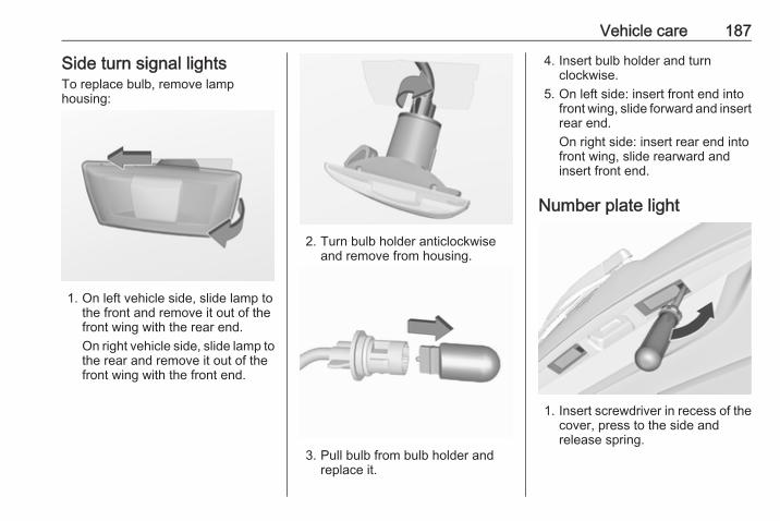
Vehicle care 187
Side turn signal lightsTo replace bulb, remove lamphousing:
1. On left vehicle side, slide lamp tothe front and remove it out of thefront wing with the rear end.On right vehicle side, slide lamp tothe rear and remove it out of thefront wing with the front end.
2. Turn bulb holder anticlockwiseand remove from housing.
3. Pull bulb from bulb holder andreplace it.
4. Insert bulb holder and turnclockwise.
5. On left side: insert front end intofront wing, slide forward and insertrear end.On right side: insert rear end intofront wing, slide rearward andinsert front end.
Number plate light
1. Insert screwdriver in recess of thecover, press to the side andrelease spring.

188 Vehicle care
2. Remove lamp downwards, takingcare not to pull on the cable.
3. Remove bulb holder from lamphousing by turning anticlockwise.
4. Pull bulb from bulb holder andreplace it.
5. Insert bulb holder into lamphousing and turn clockwise.
6. Insert lamp into bumper and letengage.
Interior lightsCourtesy light, reading lightsHave bulbs replaced by a workshop.
Load compartment lightHave bulbs replaced by a workshop.
Instrument panelilluminationHave bulbs replaced by a workshop.
Electrical systemFusesData on the replacement fuse mustmatch the data on the defective fuse.There are three fuse boxes in thevehicle:● in the front left of the engine
compartment● in left-hand drive vehicles, in the
interior behind the storagecompartment, or, in right-handdrive vehicles, behind theglovebox
● behind a cover on the left side ofthe load compartment
Before replacing a fuse, turn off therespective switch and the ignition.A blown fuse can be recognized by itsmelted wire. Do not replace the fuseuntil the cause of the fault has beenremedied.Some functions are protected byseveral fuses.Fuses may also be inserted withoutexistence of a function.

Vehicle care 189
Fuse extractorA fuse extractor may be located in thefuse box in the engine compartment.
Place the fuse extractor on thevarious types of fuse from the top orside, and withdraw fuse.

190 Vehicle care
Engine compartment fusebox
The fuse box is in the front left of theengine compartment.Disengage the cover, lift it upwardsand remove.After having changed defective fusesclose the fuse box cover and pressuntil it engages.If the fuse box cover is not closedcorrectly, malfunctions may occur.
No. Circuit
1 Starter
2 –
3 Fuel filter/Cooling
4 Horn
5 Terminal 30
6 Engine control module/Trans‐mission control unit
7 Fog light
8 Engine cooling
9 Engine cooling
10 Vacuum pump
11 Ignition/Preheating
12 Headlamp levelling
13 Air conditioning system/Terminal 15
14 Transmission control unit
15 High beam right
16 High beam left
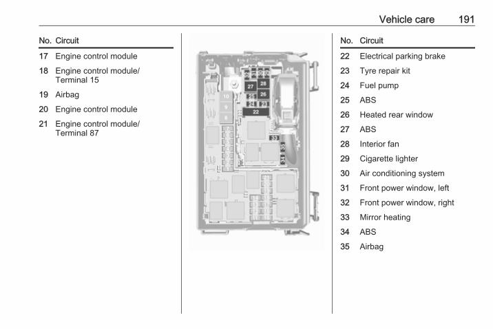
Vehicle care 191
No. Circuit
17 Engine control module
18 Engine control module/Terminal 15
19 Airbag
20 Engine control module
21 Engine control module/Terminal 87
No. Circuit
22 Electrical parking brake
23 Tyre repair kit
24 Fuel pump
25 ABS
26 Heated rear window
27 ABS
28 Interior fan
29 Cigarette lighter
30 Air conditioning system
31 Front power window, left
32 Front power window, right
33 Mirror heating
34 ABS
35 Airbag
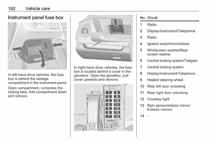
192 Vehicle care
Instrument panel fuse box
In left-hand drive vehicles, the fusebox is behind the storagecompartment in the instrument panel.Open compartment, compress thelocking tabs, fold compartment downand remove.
In right-hand drive vehicles, the fusebox is located behind a cover in theglovebox. Open the glovebox, pullcover upwards and remove.
No. Circuit
1 Radio
2 Display/Instrument/Telephone
3 Radio
4 Ignition switch/Immobiliser
5 Windscreen washer/Rearscreen washer
6 Central locking system/Tailgate
7 Central locking system
8 Display/Instrument/Telephone
9 Heated steering wheel
10 Rear left door unlocking
11 Rear right door unlocking
12 Courtesy light
13 Rain sensor/Interior mirror/Exterior mirrors
14 –
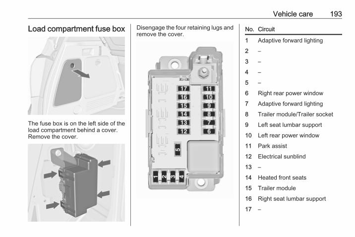
Vehicle care 193
Load compartment fuse box
The fuse box is on the left side of theload compartment behind a cover.Remove the cover.
Disengage the four retaining lugs andremove the cover.
No. Circuit
1 Adaptive forward lighting
2 –
3 –
4 –
5 –
6 Right rear power window
7 Adaptive forward lighting
8 Trailer module/Trailer socket
9 Left seat lumbar support
10 Left rear power window
11 Park assist
12 Electrical sunblind
13 –
14 Heated front seats
15 Trailer module
16 Right seat lumbar support
17 –
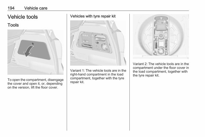
194 Vehicle care
Vehicle toolsTools
To open the compartment, disengagethe cover and open it, or, dependingon the version, lift the floor cover.
Vehicles with tyre repair kit
Variant 1: The vehicle tools are in theright-hand compartment in the loadcompartment, together with the tyrerepair kit.
Variant 2: The vehicle tools are in thecompartment under the floor cover inthe load compartment, together withthe tyre repair kit.
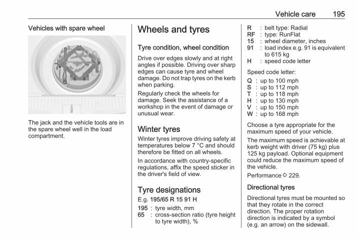
Vehicle care 195
Vehicles with spare wheel
The jack and the vehicle tools are inthe spare wheel well in the loadcompartment.
Wheels and tyres
Tyre condition, wheel conditionDrive over edges slowly and at rightangles if possible. Driving over sharpedges can cause tyre and wheeldamage. Do not trap tyres on the kerbwhen parking.Regularly check the wheels fordamage. Seek the assistance of aworkshop in the event of damage orunusual wear.
Winter tyresWinter tyres improve driving safety attemperatures below 7 °C and shouldtherefore be fitted on all wheels.In accordance with country-specificregulations, affix the speed sticker inthe driver's field of view.
Tyre designationsE.g. 195/65 R 15 91 H195 : tyre width, mm65 : cross-section ratio (tyre height
to tyre width), %
R : belt type: RadialRF : type: RunFlat15 : wheel diameter, inches91 : load index e.g. 91 is equivalent
to 615 kgH : speed code letter
Speed code letter:Q : up to 100 mphS : up to 112 mphT : up to 118 mphH : up to 130 mphV : up to 150 mphW : up to 168 mph
Choose a tyre appropriate for themaximum speed of your vehicle.The maximum speed is achievable atkerb weight with driver (75 kg) plus125 kg payload. Optional equipmentcould reduce the maximum speed ofthe vehicle.Performance 3 229.
Directional tyresDirectional tyres must be mounted sothat they rotate in the correctdirection. The proper rotationdirection is indicated by a symbol(e.g. an arrow) on the sidewall.

196 Vehicle care
Tyre pressureCheck the pressure of cold tyres atleast every 14 days and before anylong journey. Do not forget the sparewheel. This also applies to vehicleswith tyre pressure monitoring system.Unscrew the valve cap.
Tyre pressure 3 234.The tyre pressure information labelon the right door frame indicates theoriginal equipment tyres and thecorrespondent tyre pressures.The tyre pressure data refers to coldtyres. It applies to summer and wintertyres.
Always inflate the spare tyre to thepressure specified for full load.The ECO tyre pressure serves toachieve the smallest amount of fuelconsumption possible.Incorrect tyre pressures will impairsafety, vehicle handling, comfort andfuel economy and will increase tyrewear.Tyre pressures differ depending onvarious options. For the correct tyrepressure value, follow the procedurebelow:1. Identify the engine identifier code.
Engine data 3 227.2. Identify the respective tyre.
The tyre pressure tables show allpossible tyre combinations 3 234.For the tyres approved for yourvehicle, refer to the EEC Certificate ofConformity provided with your vehicleor other national registrationdocuments.The driver is responsible for correctadjustment of tyre pressure.
9 Warning
If the pressure is too low, this canresult in considerable tyre warm-up and internal damage, leading totread separation and even to tyreblow-out at high speeds.
9 Warning
For specific tyres therecommended tyre pressure asshown in the tyre pressure tablemay exceed the maximum tyrepressure as indicated on the tyre.Never exceed the maximum tyrepressure as indicated on the tyre.
If the tyre pressure must be reducedor increased on a vehicle with tyrepressure monitoring system, switchoff ignition.
Temperature dependencyThe tyre pressure depends on thetemperature of the tyre. Duringdriving, tyre temperature andpressure increase. Tyre pressure
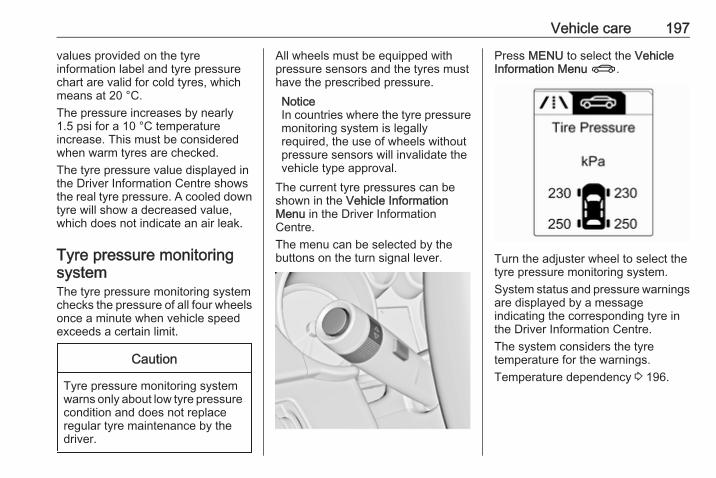
Vehicle care 197
values provided on the tyreinformation label and tyre pressurechart are valid for cold tyres, whichmeans at 20 °C.The pressure increases by nearly1.5 psi for a 10 °C temperatureincrease. This must be consideredwhen warm tyres are checked.The tyre pressure value displayed inthe Driver Information Centre showsthe real tyre pressure. A cooled downtyre will show a decreased value,which does not indicate an air leak.
Tyre pressure monitoringsystemThe tyre pressure monitoring systemchecks the pressure of all four wheelsonce a minute when vehicle speedexceeds a certain limit.
Caution
Tyre pressure monitoring systemwarns only about low tyre pressurecondition and does not replaceregular tyre maintenance by thedriver.
All wheels must be equipped withpressure sensors and the tyres musthave the prescribed pressure.NoticeIn countries where the tyre pressuremonitoring system is legallyrequired, the use of wheels withoutpressure sensors will invalidate thevehicle type approval.
The current tyre pressures can beshown in the Vehicle InformationMenu in the Driver InformationCentre.The menu can be selected by thebuttons on the turn signal lever.
Press MENU to select the VehicleInformation Menu X.
Turn the adjuster wheel to select thetyre pressure monitoring system.System status and pressure warningsare displayed by a messageindicating the corresponding tyre inthe Driver Information Centre.The system considers the tyretemperature for the warnings.Temperature dependency 3 196.
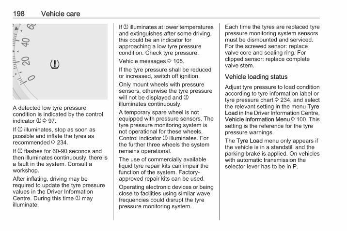
198 Vehicle care
A detected low tyre pressurecondition is indicated by the controlindicator w 3 97.If w illuminates, stop as soon aspossible and inflate the tyres asrecommended 3 234.If w flashes for 60-90 seconds andthen illuminates continuously, there isa fault in the system. Consult aworkshop.After inflating, driving may berequired to update the tyre pressurevalues in the Driver InformationCentre. During this time w mayilluminate.
If w illuminates at lower temperaturesand extinguishes after some driving,this could be an indicator forapproaching a low tyre pressurecondition. Check tyre pressure.Vehicle messages 3 105.If the tyre pressure shall be reducedor increased, switch off ignition.Only mount wheels with pressuresensors, otherwise the tyre pressurewill not be displayed and willuminates continuously.A temporary spare wheel is notequipped with pressure sensors. Thetyre pressure monitoring system isnot operational for these wheels.Control indicator w illuminates. Forthe further three wheels the systemremains operational.The use of commercially availableliquid tyre repair kits can impair thefunction of the system. Factory-approved repair kits can be used.Operating electronic devices or beingclose to facilities using similar wavefrequencies could disrupt the tyrepressure monitoring system.
Each time the tyres are replaced tyrepressure monitoring system sensorsmust be dismounted and serviced.For the screwed sensor: replacevalve core and sealing ring. Forclipped sensor: replace completevalve stem.
Vehicle loading statusAdjust tyre pressure to load conditionaccording to tyre information label ortyre pressure chart 3 234, and selectthe relevant setting in the menu TyreLoad in the Driver Information Centre,Vehicle Information Menu 3 100. Thissetting is the reference for the tyrepressure warnings.The Tyre Load menu only appears ifthe vehicle is in a standstill and theparking brake is applied. On vehicleswith automatic transmission theselector lever has to be in P.
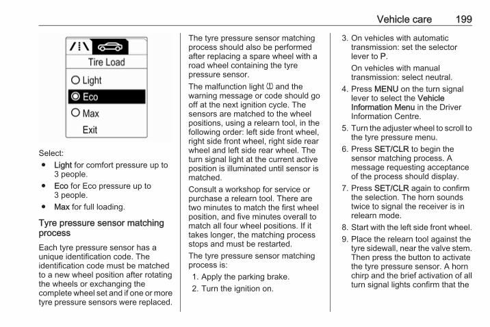
Vehicle care 199
Select:● Light for comfort pressure up to
3 people.● Eco for Eco pressure up to
3 people.● Max for full loading.
Tyre pressure sensor matchingprocessEach tyre pressure sensor has aunique identification code. Theidentification code must be matchedto a new wheel position after rotatingthe wheels or exchanging thecomplete wheel set and if one or moretyre pressure sensors were replaced.
The tyre pressure sensor matchingprocess should also be performedafter replacing a spare wheel with aroad wheel containing the tyrepressure sensor.The malfunction light w and thewarning message or code should gooff at the next ignition cycle. Thesensors are matched to the wheelpositions, using a relearn tool, in thefollowing order: left side front wheel,right side front wheel, right side rearwheel and left side rear wheel. Theturn signal light at the current activeposition is illuminated until sensor ismatched.Consult a workshop for service orpurchase a relearn tool. There aretwo minutes to match the first wheelposition, and five minutes overall tomatch all four wheel positions. If ittakes longer, the matching processstops and must be restarted.The tyre pressure sensor matchingprocess is:1. Apply the parking brake.2. Turn the ignition on.
3. On vehicles with automatictransmission: set the selectorlever to P.On vehicles with manualtransmission: select neutral.
4. Press MENU on the turn signallever to select the VehicleInformation Menu in the DriverInformation Centre.
5. Turn the adjuster wheel to scroll tothe tyre pressure menu.
6. Press SET/CLR to begin thesensor matching process. Amessage requesting acceptanceof the process should display.
7. Press SET/CLR again to confirmthe selection. The horn soundstwice to signal the receiver is inrelearn mode.
8. Start with the left side front wheel.9. Place the relearn tool against the
tyre sidewall, near the valve stem.Then press the button to activatethe tyre pressure sensor. A hornchirp and the brief activation of allturn signal lights confirm that the
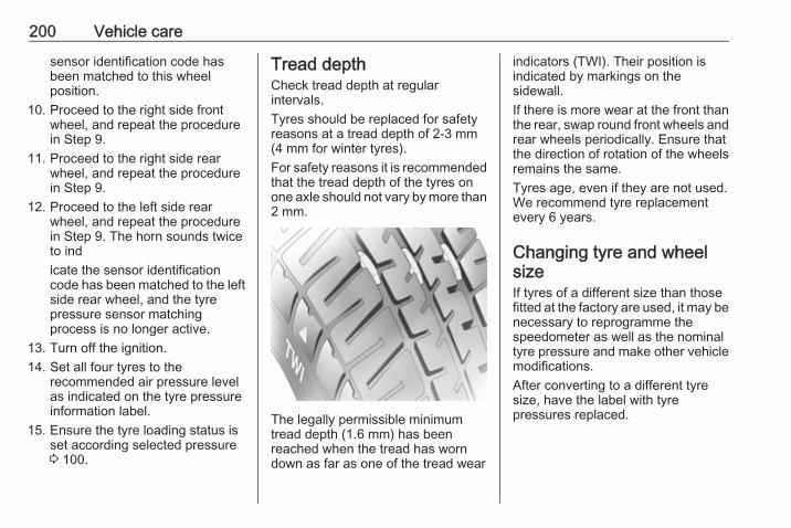
200 Vehicle care
sensor identification code hasbeen matched to this wheelposition.
10. Proceed to the right side frontwheel, and repeat the procedurein Step 9.
11. Proceed to the right side rearwheel, and repeat the procedurein Step 9.
12. Proceed to the left side rearwheel, and repeat the procedurein Step 9. The horn sounds twiceto indicate the sensor identificationcode has been matched to the leftside rear wheel, and the tyrepressure sensor matchingprocess is no longer active.
13. Turn off the ignition.14. Set all four tyres to the
recommended air pressure levelas indicated on the tyre pressureinformation label.
15. Ensure the tyre loading status isset according selected pressure3 100.
Tread depthCheck tread depth at regularintervals.Tyres should be replaced for safetyreasons at a tread depth of 2-3 mm(4 mm for winter tyres).For safety reasons it is recommendedthat the tread depth of the tyres onone axle should not vary by more than2 mm.
The legally permissible minimumtread depth (1.6 mm) has beenreached when the tread has worndown as far as one of the tread wear
indicators (TWI). Their position isindicated by markings on thesidewall.If there is more wear at the front thanthe rear, swap round front wheels andrear wheels periodically. Ensure thatthe direction of rotation of the wheelsremains the same.Tyres age, even if they are not used.We recommend tyre replacementevery 6 years.
Changing tyre and wheelsizeIf tyres of a different size than thosefitted at the factory are used, it may benecessary to reprogramme thespeedometer as well as the nominaltyre pressure and make other vehiclemodifications.After converting to a different tyresize, have the label with tyrepressures replaced.
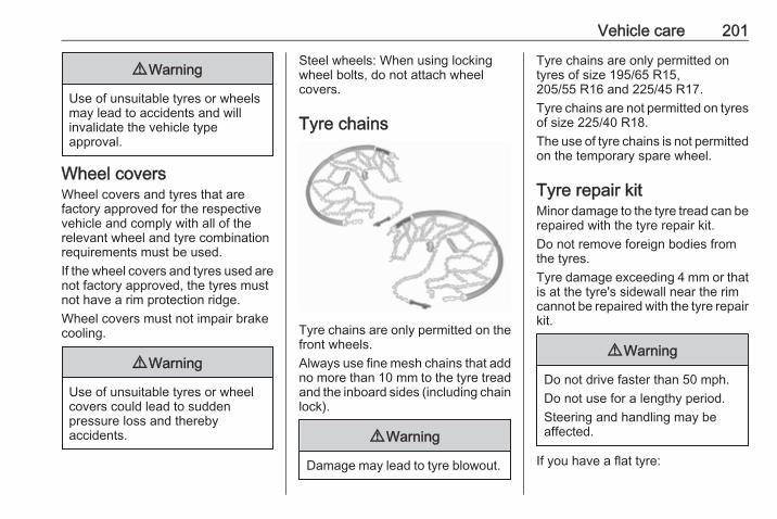
Vehicle care 201
9 Warning
Use of unsuitable tyres or wheelsmay lead to accidents and willinvalidate the vehicle typeapproval.
Wheel coversWheel covers and tyres that arefactory approved for the respectivevehicle and comply with all of therelevant wheel and tyre combinationrequirements must be used.If the wheel covers and tyres used arenot factory approved, the tyres mustnot have a rim protection ridge.Wheel covers must not impair brakecooling.
9 Warning
Use of unsuitable tyres or wheelcovers could lead to suddenpressure loss and therebyaccidents.
Steel wheels: When using lockingwheel bolts, do not attach wheelcovers.
Tyre chains
Tyre chains are only permitted on thefront wheels.Always use fine mesh chains that addno more than 10 mm to the tyre treadand the inboard sides (including chainlock).
9 Warning
Damage may lead to tyre blowout.
Tyre chains are only permitted ontyres of size 195/65 R15,205/55 R16 and 225/45 R17.Tyre chains are not permitted on tyresof size 225/40 R18.The use of tyre chains is not permittedon the temporary spare wheel.
Tyre repair kitMinor damage to the tyre tread can berepaired with the tyre repair kit.Do not remove foreign bodies fromthe tyres.Tyre damage exceeding 4 mm or thatis at the tyre's sidewall near the rimcannot be repaired with the tyre repairkit.
9 Warning
Do not drive faster than 50 mph.Do not use for a lengthy period.Steering and handling may beaffected.
If you have a flat tyre:
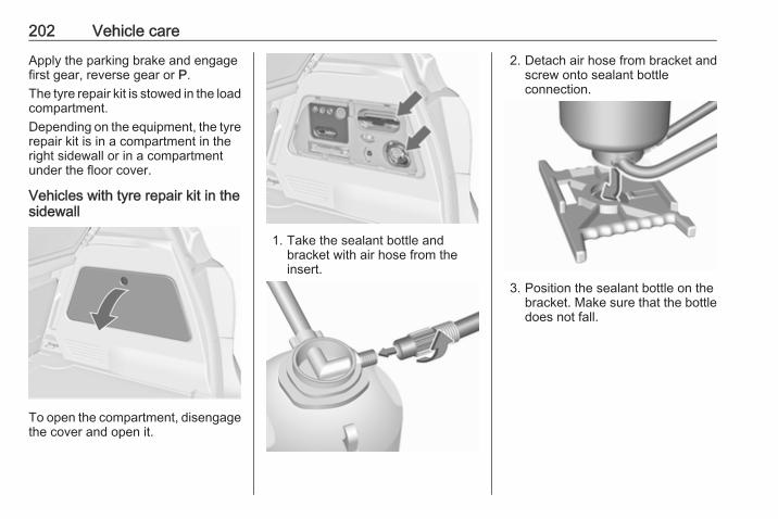
202 Vehicle care
Apply the parking brake and engagefirst gear, reverse gear or P.The tyre repair kit is stowed in the loadcompartment.Depending on the equipment, the tyrerepair kit is in a compartment in theright sidewall or in a compartmentunder the floor cover.
Vehicles with tyre repair kit in thesidewall
To open the compartment, disengagethe cover and open it.
1. Take the sealant bottle andbracket with air hose from theinsert.
2. Detach air hose from bracket andscrew onto sealant bottleconnection.
3. Position the sealant bottle on thebracket. Make sure that the bottledoes not fall.
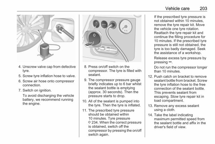
Vehicle care 203
4. Unscrew valve cap from defectivetyre.
5. Screw tyre inflation hose to valve.6. Screw air hose onto compressor
connection.7. Switch on ignition.
To avoid discharging the vehiclebattery, we recommend runningthe engine.
8. Press on/off switch on thecompressor. The tyre is filled withsealant.
9. The compressor pressure gaugebriefly indicates up to 6 bar whilstthe sealant bottle is emptying(approx. 30 seconds). Then thepressure starts to drop.
10. All of the sealant is pumped intothe tyre. Then the tyre is inflated.
11. The prescribed tyre pressureshould be obtained within10 minutes. Tyre pressure3 234. When the correct pressureis obtained, switch off thecompressor by pressing the on/offswitch again.
If the prescribed tyre pressure isnot obtained within 10 minutes,remove the tyre repair kit. Movethe vehicle one tyre rotation.Reattach the tyre repair kit andcontinue the filling procedure for10 minutes. If the prescribed tyrepressure is still not obtained, thetyre is too badly damaged. Seekthe assistance of a workshop.Release excess tyre pressure bypressing ].Do not run the compressor longerthan 10 minutes.
12. Push catch on bracket to removesealant bottle from bracket. Screwthe tyre inflation hose to the freeconnection of the sealant bottle.This prevents sealant fromescaping. Stow tyre repair kit inload compartment.
13. Remove any excess sealantusing a cloth.
14. Take the label indicatingmaximum permitted speed fromthe sealant bottle and affix in thedriver's field of view.
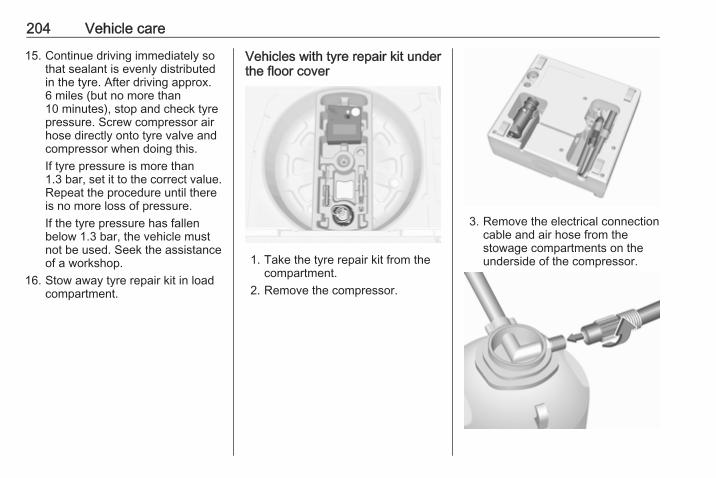
204 Vehicle care
15. Continue driving immediately sothat sealant is evenly distributedin the tyre. After driving approx.6 miles (but no more than10 minutes), stop and check tyrepressure. Screw compressor airhose directly onto tyre valve andcompressor when doing this.If tyre pressure is more than1.3 bar, set it to the correct value.Repeat the procedure until thereis no more loss of pressure.If the tyre pressure has fallenbelow 1.3 bar, the vehicle mustnot be used. Seek the assistanceof a workshop.
16. Stow away tyre repair kit in loadcompartment.
Vehicles with tyre repair kit underthe floor cover
1. Take the tyre repair kit from thecompartment.
2. Remove the compressor.
3. Remove the electrical connectioncable and air hose from thestowage compartments on theunderside of the compressor.
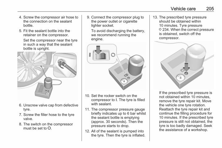
Vehicle care 205
4. Screw the compressor air hose tothe connection on the sealantbottle.
5. Fit the sealant bottle into theretainer on the compressor.Set the compressor near the tyrein such a way that the sealantbottle is upright.
6. Unscrew valve cap from defectivetyre.
7. Screw the filler hose to the tyrevalve.
8. The switch on the compressormust be set to J.
9. Connect the compressor plug tothe power outlet or cigarettelighter socket.To avoid discharging the battery,we recommend running theengine.
10. Set the rocker switch on thecompressor to I. The tyre is filledwith sealant.
11. The compressor pressure gaugebriefly indicates up to 6 bar whilstthe sealant bottle is emptying(approx. 30 seconds). Then thepressure starts to drop.
12. All of the sealant is pumped intothe tyre. Then the tyre is inflated.
13. The prescribed tyre pressureshould be obtained within10 minutes. Tyre pressure3 234. When the correct pressureis obtained, switch off thecompressor.
If the prescribed tyre pressure isnot obtained within 10 minutes,remove the tyre repair kit. Movethe vehicle one tyre rotation.Reattach the tyre repair kit andcontinue the filling procedure for10 minutes. If the prescribed tyrepressure is still not obtained, thetyre is too badly damaged. Seekthe assistance of a workshop.
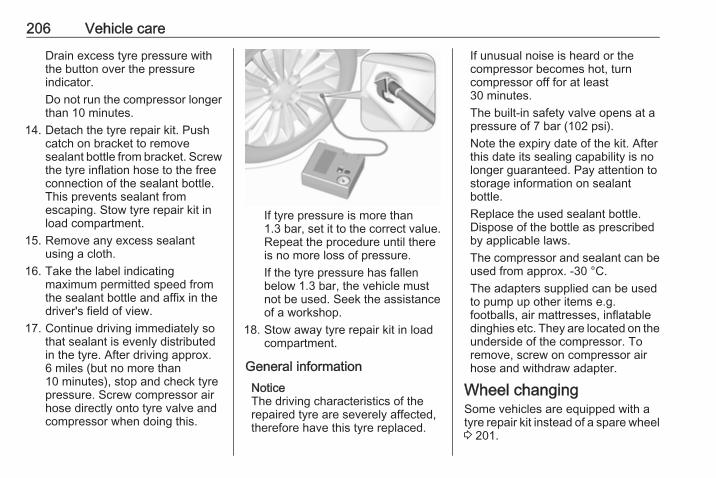
206 Vehicle care
Drain excess tyre pressure withthe button over the pressureindicator.Do not run the compressor longerthan 10 minutes.
14. Detach the tyre repair kit. Pushcatch on bracket to removesealant bottle from bracket. Screwthe tyre inflation hose to the freeconnection of the sealant bottle.This prevents sealant fromescaping. Stow tyre repair kit inload compartment.
15. Remove any excess sealantusing a cloth.
16. Take the label indicatingmaximum permitted speed fromthe sealant bottle and affix in thedriver's field of view.
17. Continue driving immediately sothat sealant is evenly distributedin the tyre. After driving approx.6 miles (but no more than10 minutes), stop and check tyrepressure. Screw compressor airhose directly onto tyre valve andcompressor when doing this.
If tyre pressure is more than1.3 bar, set it to the correct value.Repeat the procedure until thereis no more loss of pressure.If the tyre pressure has fallenbelow 1.3 bar, the vehicle mustnot be used. Seek the assistanceof a workshop.
18. Stow away tyre repair kit in loadcompartment.
General informationNoticeThe driving characteristics of therepaired tyre are severely affected,therefore have this tyre replaced.
If unusual noise is heard or thecompressor becomes hot, turncompressor off for at least30 minutes.The built-in safety valve opens at apressure of 7 bar (102 psi).Note the expiry date of the kit. Afterthis date its sealing capability is nolonger guaranteed. Pay attention tostorage information on sealantbottle.Replace the used sealant bottle.Dispose of the bottle as prescribedby applicable laws.The compressor and sealant can beused from approx. -30 °C.The adapters supplied can be usedto pump up other items e.g.footballs, air mattresses, inflatabledinghies etc. They are located on theunderside of the compressor. Toremove, screw on compressor airhose and withdraw adapter.
Wheel changingSome vehicles are equipped with atyre repair kit instead of a spare wheel3 201.
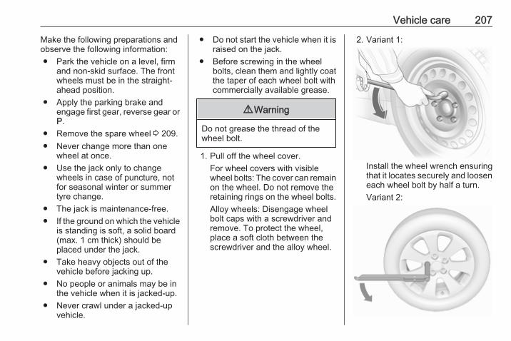
Vehicle care 207
Make the following preparations andobserve the following information:● Park the vehicle on a level, firm
and non-skid surface. The frontwheels must be in the straight-ahead position.
● Apply the parking brake andengage first gear, reverse gear orP.
● Remove the spare wheel 3 209.● Never change more than one
wheel at once.● Use the jack only to change
wheels in case of puncture, notfor seasonal winter or summertyre change.
● The jack is maintenance-free.● If the ground on which the vehicle
is standing is soft, a solid board(max. 1 cm thick) should beplaced under the jack.
● Take heavy objects out of thevehicle before jacking up.
● No people or animals may be inthe vehicle when it is jacked-up.
● Never crawl under a jacked-upvehicle.
● Do not start the vehicle when it israised on the jack.
● Before screwing in the wheelbolts, clean them and lightly coatthe taper of each wheel bolt withcommercially available grease.
9 Warning
Do not grease the thread of thewheel bolt.
1. Pull off the wheel cover.For wheel covers with visiblewheel bolts: The cover can remainon the wheel. Do not remove theretaining rings on the wheel bolts.Alloy wheels: Disengage wheelbolt caps with a screwdriver andremove. To protect the wheel,place a soft cloth between thescrewdriver and the alloy wheel.
2. Variant 1:
Install the wheel wrench ensuringthat it locates securely and looseneach wheel bolt by half a turn.Variant 2:

208 Vehicle care
Fold out the wheel wrench andinstall ensuring that it locatessecurely and loosen each wheelbolt by half a turn.The wheels might be protected bylocking wheel bolts. To loosenthese specific bolts first attach theadapter onto the head of the boltbefore installing the wheelwrench. The adapter is located inthe glovebox.
3. Ensure the jack is positionedcorrectly with the vehicle jackingpoints.
4. Variant 1:
Set the jack to the necessaryheight. Position it directly belowthe jacking point in a manner thatprevents it from slipping.
Attach jack handle and with thejack correctly aligned rotatehandle until wheel is clear of theground.Variant 2:
Set the jack to the necessaryheight. Position it directly belowthe jacking point in a manner thatprevents it from slipping.
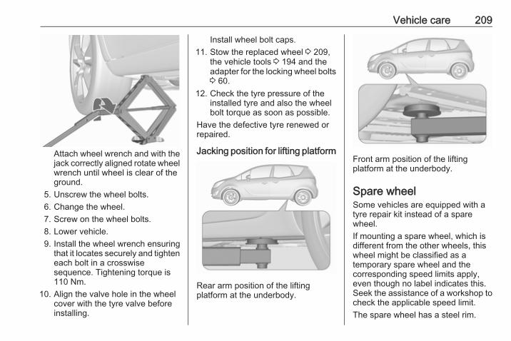
Vehicle care 209
Attach wheel wrench and with thejack correctly aligned rotate wheelwrench until wheel is clear of theground.
5. Unscrew the wheel bolts.6. Change the wheel.7. Screw on the wheel bolts.8. Lower vehicle.9. Install the wheel wrench ensuring
that it locates securely and tighteneach bolt in a crosswisesequence. Tightening torque is110 Nm.
10. Align the valve hole in the wheelcover with the tyre valve beforeinstalling.
Install wheel bolt caps.11. Stow the replaced wheel 3 209,
the vehicle tools 3 194 and theadapter for the locking wheel bolts3 60.
12. Check the tyre pressure of theinstalled tyre and also the wheelbolt torque as soon as possible.
Have the defective tyre renewed orrepaired.
Jacking position for lifting platform
Rear arm position of the liftingplatform at the underbody.
Front arm position of the liftingplatform at the underbody.
Spare wheelSome vehicles are equipped with atyre repair kit instead of a sparewheel.If mounting a spare wheel, which isdifferent from the other wheels, thiswheel might be classified as atemporary spare wheel and thecorresponding speed limits apply,even though no label indicates this.Seek the assistance of a workshop tocheck the applicable speed limit.The spare wheel has a steel rim.
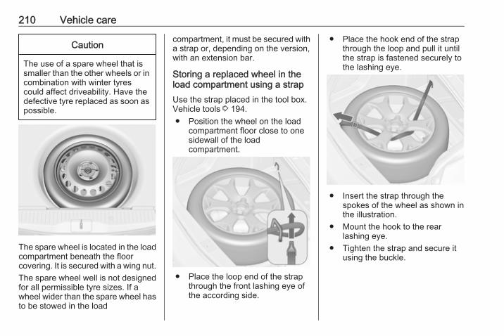
210 Vehicle care
Caution
The use of a spare wheel that issmaller than the other wheels or incombination with winter tyrescould affect driveability. Have thedefective tyre replaced as soon aspossible.
The spare wheel is located in the loadcompartment beneath the floorcovering. It is secured with a wing nut.The spare wheel well is not designedfor all permissible tyre sizes. If awheel wider than the spare wheel hasto be stowed in the load
compartment, it must be secured witha strap or, depending on the version,with an extension bar.
Storing a replaced wheel in theload compartment using a strapUse the strap placed in the tool box.Vehicle tools 3 194.● Position the wheel on the load
compartment floor close to onesidewall of the loadcompartment.
● Place the loop end of the strapthrough the front lashing eye ofthe according side.
● Place the hook end of the strapthrough the loop and pull it untilthe strap is fastened securely tothe lashing eye.
● Insert the strap through thespokes of the wheel as shown inthe illustration.
● Mount the hook to the rearlashing eye.
● Tighten the strap and secure itusing the buckle.
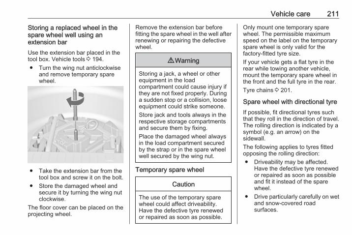
Vehicle care 211
Storing a replaced wheel in thespare wheel well using anextension barUse the extension bar placed in thetool box. Vehicle tools 3 194.● Turn the wing nut anticlockwise
and remove temporary sparewheel.
● Take the extension bar from thetool box and screw it on the bolt.
● Store the damaged wheel andsecure it by turning the wing nutclockwise.
The floor cover can be placed on theprojecting wheel.
Remove the extension bar beforefitting the spare wheel in the well afterrenewing or repairing the defectivewheel.
9 Warning
Storing a jack, a wheel or otherequipment in the loadcompartment could cause injury ifthey are not fixed properly. Duringa sudden stop or a collision, looseequipment could strike someone.Store jack and tools always in therespective storage compartmentsand secure them by fixing.Place the damaged wheel alwaysin the load compartment securedby the strap or in the spare wheelwell secured by the wing nut.
Temporary spare wheel
Caution
The use of the temporary sparewheel could affect driveability.Have the defective tyre renewedor repaired as soon as possible.
Only mount one temporary sparewheel. The permissible maximumspeed on the label on the temporaryspare wheel is only valid for thefactory-fitted tyre size.If your vehicle gets a flat tyre in therear while towing another vehicle,mount the temporary spare wheel inthe front and the full tyre in the rear.Tyre chains 3 201.
Spare wheel with directional tyreIf possible, fit directional tyres suchthat they roll in the direction of travel.The rolling direction is indicated by asymbol (e.g. an arrow) on thesidewall.The following applies to tyres fittedopposing the rolling direction:● Driveability may be affected.
Have the defective tyre renewedor repaired as soon as possibleand fit it instead of the sparewheel.
● Drive particularly carefully on wetand snow-covered roadsurfaces.
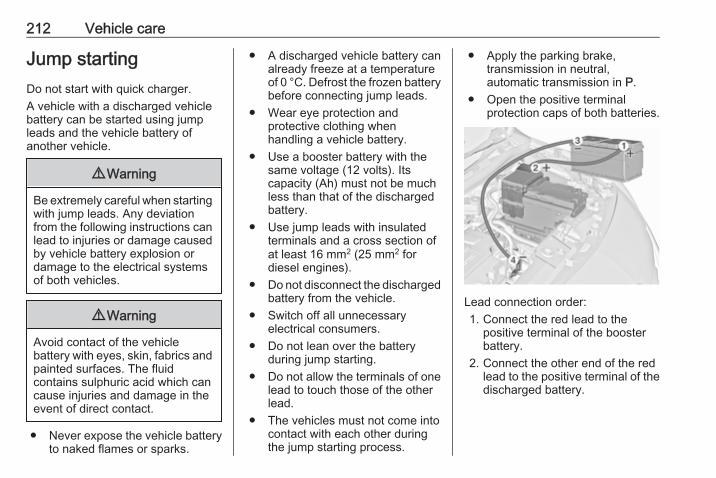
212 Vehicle care
Jump startingDo not start with quick charger.A vehicle with a discharged vehiclebattery can be started using jumpleads and the vehicle battery ofanother vehicle.
9 Warning
Be extremely careful when startingwith jump leads. Any deviationfrom the following instructions canlead to injuries or damage causedby vehicle battery explosion ordamage to the electrical systemsof both vehicles.
9 Warning
Avoid contact of the vehiclebattery with eyes, skin, fabrics andpainted surfaces. The fluidcontains sulphuric acid which cancause injuries and damage in theevent of direct contact.
● Never expose the vehicle batteryto naked flames or sparks.
● A discharged vehicle battery canalready freeze at a temperatureof 0 °C. Defrost the frozen batterybefore connecting jump leads.
● Wear eye protection andprotective clothing whenhandling a vehicle battery.
● Use a booster battery with thesame voltage (12 volts). Itscapacity (Ah) must not be muchless than that of the dischargedbattery.
● Use jump leads with insulatedterminals and a cross section ofat least 16 mm2 (25 mm2 fordiesel engines).
● Do not disconnect the dischargedbattery from the vehicle.
● Switch off all unnecessaryelectrical consumers.
● Do not lean over the batteryduring jump starting.
● Do not allow the terminals of onelead to touch those of the otherlead.
● The vehicles must not come intocontact with each other duringthe jump starting process.
● Apply the parking brake,transmission in neutral,automatic transmission in P.
● Open the positive terminalprotection caps of both batteries.
Lead connection order:1. Connect the red lead to the
positive terminal of the boosterbattery.
2. Connect the other end of the redlead to the positive terminal of thedischarged battery.
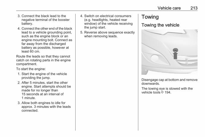
Vehicle care 213
3. Connect the black lead to thenegative terminal of the boosterbattery.
4. Connect the other end of the blacklead to a vehicle grounding point,such as the engine block or anengine mounting bolt. Connect asfar away from the dischargedbattery as possible, however atleast 60 cm.
Route the leads so that they cannotcatch on rotating parts in the enginecompartment.To start the engine:1. Start the engine of the vehicle
providing the jump.2. After 5 minutes, start the other
engine. Start attempts should bemade for no longer than15 seconds at an interval of1 minute.
3. Allow both engines to idle forapprox. 3 minutes with the leadsconnected.
4. Switch on electrical consumers(e.g. headlights, heated rearwindow) of the vehicle receivingthe jump start.
5. Reverse above sequence exactlywhen removing leads.
TowingTowing the vehicle
Disengage cap at bottom and removedownwards.The towing eye is stowed with thevehicle tools 3 194.
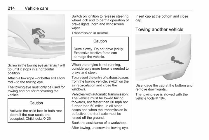
214 Vehicle care
Screw in the towing eye as far as it willgo until it stops in a horizontalposition.Attach a tow rope – or better still a towrod – to the towing eye.The towing eye must only be used fortowing and not for recovering thevehicle.
Caution
Activate the child lock in both reardoors if the rear seats areoccupied. Child locks 3 25.
Switch on ignition to release steeringwheel lock and to permit operation ofbrake lights, horn and windscreenwiper.Transmission in neutral.
Caution
Drive slowly. Do not drive jerkily.Excessive tractive force candamage the vehicle.
When the engine is not running,considerably more force is needed tobrake and steer.To prevent the entry of exhaust gasesfrom the towing vehicle, switch on theair recirculation and close thewindows.Vehicles with automatic transmission:The vehicle must be towed facingforwards, not faster than 50 mph norfurther than 60 miles. In all othercases and when the transmission isdefective, the front axle must beraised off the ground.Seek the assistance of a workshop.After towing, unscrew the towing eye.
Insert cap at the bottom and closecap.
Towing another vehicle
Disengage the cap at the bottom andremove downwards.The towing eye is stowed with thevehicle tools 3 194.
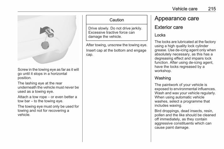
Vehicle care 215
Screw in the towing eye as far as it willgo until it stops in a horizontalposition.The lashing eye at the rearunderneath the vehicle must never beused as a towing eye.Attach a tow rope – or even better atow bar – to the towing eye.The towing eye must only be used fortowing and not for recovering avehicle.
Caution
Drive slowly. Do not drive jerkily.Excessive tractive force candamage the vehicle.
After towing, unscrew the towing eye.Insert cap at the bottom and engagecap.
Appearance careExterior careLocksThe locks are lubricated at the factoryusing a high quality lock cylindergrease. Use de-icing agent only whenabsolutely necessary, as this has adegreasing effect and impairs lockfunction. After using de-icing agent,have the locks regreased by aworkshop.
WashingThe paintwork of your vehicle isexposed to environmental influences.Wash and wax your vehicle regularly.When using automatic vehiclewashes, select a programme thatincludes waxing.Bird droppings, dead insects, resin,pollen and the like should be cleanedoff immediately, as they containaggressive constituents which cancause paint damage.
216 Vehicle care
If using a vehicle wash, comply withthe vehicle wash manufacturer'sinstructions. The windscreen wiperand rear window wiper must beswitched off. Remove antenna andexternal accessories such as roofracks etc.If you wash your vehicle by hand,make sure that the insides of thewheel housings are also thoroughlyrinsed out.Clean edges and folds on openeddoors and the bonnet as well as theareas they cover.
Caution
Always use a cleaning agent witha pH value of 4 to 9.Do not use cleaning agents on hotsurfaces.
Have the door hinges of all doorsgreased by a workshop.Do not clean the engine compartmentwith a steam-jet or high-pressure jetcleaner.
Thoroughly rinse and leather-off thevehicle. Rinse leather frequently. Useseparate leathers for painted andglass surfaces: remnants of wax onthe windows will impair vision.
Exterior lightsHeadlight and other light covers aremade of plastic. Do not use anyabrasive or caustic agents, do not usean ice scraper, and do not clean themdry.
Polishing and waxingWax the vehicle regularly (at thelatest when water no longer beads).Otherwise, the paintwork will dry out.Polishing is necessary only if the painthas become dull or if solid depositshave become attached to it.Paintwork polish with silicone forms aprotective film, making waxingunnecessary.Plastic body parts must not be treatedwith wax or polishing agents.
Windows and windscreen wiperbladesUse a soft lint-free cloth or chamoisleather together with window cleanerand insect remover.When cleaning the rear window frominside, always wipe in parallel to theheating element to prevent damage.For mechanical removal of ice, use asharp-edged ice scraper. Press thescraper firmly against the glass sothat no dirt can get under it andscratch the glass.Remove dirt residues from smearingwiper blades by using a soft cloth andwindow cleaner. Also make sure toremove any residues such as wax,insect residues and similar from thewindow.Ice residues, pollution and continuouswiping on dry windows will damage oreven destroy the wiper blades.

Vehicle care 217
MoonroofNever clean with solvents or abrasiveagents, fuels, aggressive media (e.g.paint cleaner, acetone-containingsolutions etc.), acidic or highlyalkaline media or abrasive pads. Donot apply wax or polishing agents tothe middle part of the moonroof.
Wheels and tyresDo not use high-pressure jetcleaners.Clean rims with a pH-neutral wheelcleaner.Rims are painted and can be treatedwith the same agents as the body.
Paintwork damageRectify minor paintwork damage witha touch-up pen before rust forms.Have more extensive damage or rustareas repaired by a workshop.
UnderbodySome areas of the vehicle underbodyhave a PVC undercoating while othercritical areas have a durableprotective wax coating.
After the underbody is washed, checkthe underbody and have it waxed ifnecessary.Bitumen/rubber materials coulddamage the PVC coating. Haveunderbody work carried out by aworkshop.Before and after winter, wash theunderbody and have the protectivewax coating checked.
Liquid gas system
9 Danger
Liquid gas is heavier than air andcan collect in sink points.Take care when performing workat the underbody in a pit.
For painting work and when using adrying booth at a temperature above60 °C, the liquid gas tank must beremoved.Do not make any modifications to theliquid gas system.
Towing equipmentDo not clean the coupling ball bar witha steam-jet or high-pressure jetcleaner.
Rear carrier systemClean the rear carrier system with asteam-jet or high-pressure jet cleanerat least once a year.Operate the rear carrier systemperiodically if not in regular use, inparticular during winter.
Interior careInterior and upholsteryOnly clean the vehicle interior,including the instrument panel fasciaand panelling, with a dry cloth orinterior cleaner.Clean the leather upholstery withclear water and a soft cloth. In case ofheavy soiling, use leather care.The instrument cluster and thedisplays should only be cleaned usinga soft damp cloth. If necessary use aweak soap solution.
218 Vehicle care
Clean fabric upholstery with avacuum cleaner and brush. Removestains with an upholstery cleaner.Clothing fabrics may not becolourfast. This could cause visiblediscolourations, especially on light-coloured upholstery. Removablestains and discolourations should becleaned as soon as possible.Clean seat belts with lukewarm wateror interior cleaner.
Caution
Close Velcro fasteners as openVelcro fasteners on clothing coulddamage seat upholstery.The same applies to clothing withsharp-edged objects, like zips orbelts or studded jeans.
Plastic and rubber partsPlastic and rubber parts can becleaned with the same cleaner asused to clean the body. Use interiorcleaner if necessary. Do not use anyother agent. Avoid solvents and petrolin particular. Do not use high-pressure jet cleaners.

Service and maintenance 219
Service andmaintenance
General information ................... 219Service information .................. 219
Recommended fluids, lubricantsand parts .................................... 220
Recommended fluids andlubricants ................................ 220
General informationService informationIn order to ensure economical andsafe vehicle operation and tomaintain the value of your vehicle, itis of vital importance that allmaintenance work is carried out at theproper intervals as specified.The detailed, up-to-date serviceschedule for your vehicle is availableat the workshop.Service display 3 90.
European service intervalsMaintenance of your vehicle isrequired every 20,000 miles or afterone year, whichever occurs first,unless otherwise indicated in theservice display.A shorter service interval can be validfor severe driving behaviour, e.g. fortaxis and police vehicles.The European service intervals arevalid for the following countries:
Andorra, Austria, Belgium, Bosnia-Herzegovina, Bulgaria, Croatia,Cyprus, Czech Republic, Denmark,Estonia, Finland, France, Germany,Greece, Greenland, Hungary,Iceland, Ireland, Italy, Latvia,Liechtenstein, Lithuania,Luxembourg, Macedonia, Malta,Monaco, Montenegro, Netherlands,Norway, Poland, Portugal, Romania,San Marino, Serbia, Slovakia,Slovenia, Spain, Sweden,Switzerland, United Kingdom.Service display 3 90.
International service intervalsMaintenance of your vehicle isrequired every 10,000 miles or afterone year, whichever occurs first,unless otherwise indicated in theservice display.The international service intervals arevalid for the countries which are notlisted in the European serviceintervals.Service display 3 90.
220 Service and maintenance
ConfirmationsConfirmation of service is recorded inthe Service and warranty booklet.The date and mileage is completedwith the stamp and signature of theservicing workshop.Make sure that the Service andwarranty booklet is completedcorrectly as continuous proof ofservice is essential if any warranty orgoodwill claims are to be met, and isalso a benefit when selling thevehicle.
Service interval with remainingengine oil life durationThe service interval is based onseveral parameters depending onusage.The service display lets you knowwhen to change the engine oil.Service display 3 90.
Recommended fluids,lubricants and partsRecommended fluids andlubricantsOnly use products that meet therecommended specifications.
9 Warning
Operating materials arehazardous and could bepoisonous. Handle with care. Payattention to information given onthe containers.
Engine oilEngine oil is identified by its qualityand its viscosity. Quality is moreimportant than viscosity whenselecting which engine oil to use. Theoil quality ensures e.g. enginecleanliness, wear protection and oilaging control, whereas viscositygrade gives information on the oil'sthickness over a temperature range.
Dexos is the newest engine oil qualitythat provides optimum protection forgasoline and diesel engines. If it isunavailable, engine oils of other listedqualities have to be used.Recommendations for gasolineengines are also valid forCompressed Natural Gas (CNG),Liquified Petroleum Gas (LPG) andEthanol (E85) fuelled engines.Select the appropriate engine oilbased on its quality and on theminimum ambient temperature3 224.
Topping up engine oilEngine oils of different manufacturersand brands can be mixed as long asthey comply with the required engineoil quality and viscosity.Use of engine oil with onlyACEA A1/B1 or only A5/B5 quality isprohibited, since it can cause long-term engine damage under certainoperating conditions.Select the appropriate engine oilbased on its quality and on theminimum ambient temperature3 224.

Service and maintenance 221
Additional engine oil additivesThe use of additional engine oiladditives could cause damage andinvalidate the warranty.
Engine oil viscosity gradesThe SAE viscosity grade givesinformation of the thickness of the oil.Multigrade oil is indicated by twofigures, e.g. SAE 5W-30. The firstfigure, followed by a W, indicates thelow temperature viscosity and thesecond figure the high temperatureviscosity.Select the appropriate viscosity gradedepending on the minimum ambienttemperature 3 224.All of the recommended viscositygrades are suitable for high ambienttemperatures.
Coolant and antifreezeUse only organic acid type-long lifecoolant (LLC) antifreeze approved forthe vehicle. Consult a workshop.The system is factory filled withcoolant designed for excellentcorrosion protection and frostprotection down to approx. -28 °C. In
northern countries with very lowtemperatures the factory filled coolantprovides frost protection down toapprox. -37 °C. This concentrationshould be maintained all year round.The use of additional coolantadditives that intend to give additionalcorrosion protection or seal againstminor leaks can cause functionproblems. Liability for consequencesresulting from the use of additionalcoolant additives will be rejected.
Brake and clutch fluidOver time, brake fluid absorbsmoisture which will reduce brakingeffectiveness. The brake fluid shouldtherefore be replaced at the specifiedinterval.
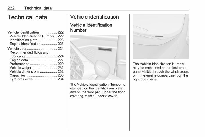
222 Technical data
Technical data
Vehicle identification .................. 222Vehicle Identification Number .. 222Identification plate ................... 223Engine identification ................ 223
Vehicle data ............................... 224Recommended fluids andlubricants ................................ 224
Engine data ............................. 227Performance ............................ 229Vehicle weight ......................... 231Vehicle dimensions ................. 232Capacities ................................ 233Tyre pressures ........................ 234
Vehicle identificationVehicle IdentificationNumber
The Vehicle Identification Number isstamped on the identification plateand on the floor pan, under the floorcovering, visible under a cover.
The Vehicle Identification Numbermay be embossed on the instrumentpanel visible through the windscreen,or in the engine compartment on theright body panel.

Technical data 223
Identification plate
The identification plate is located onthe rear or front right door frame.
Information on identification label:1 : manufacturer2 : type approval number3 : vehicle identification number4 : permissible gross vehicle weight
rating in kg5 : permissible gross train weight in
kg6 : maximum permissible front axle
load in kg7 : maximum permissible rear axle
load in kg8 : vehicle-specific or country-
specific data
The combined total of front and rearaxle loads must not exceed thepermissible gross vehicle weight. Forexample, if the front axle is bearing itsmaximum permissible load, the rearaxle can only bear a load that is equalto the gross vehicle weight minus thefront axle load.The technical data is determined inaccordance with EuropeanCommunity standards. We reservethe right to make modifications.Specifications in the vehicledocuments always have priority overthose given in this manual.
Engine identificationThe technical data tables show theengine identifier code. Engine data3 227.To identify the respective engine,refer to the engine power in the EECCertificate of Conformity providedwith your vehicle or other nationalregistration documents.The Certificate of Conformity showsthe engine identifier code, othernational publications may show theengineering code. Check pistondisplacement and engine power toidentify the respective engine.
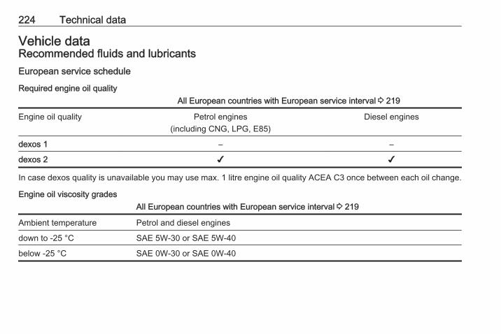
224 Technical data
Vehicle dataRecommended fluids and lubricantsEuropean service schedule
Required engine oil qualityAll European countries with European service interval 3 219
Engine oil quality Petrol engines(including CNG, LPG, E85)
Diesel engines
dexos 1 – –
dexos 2 ✔ ✔
In case dexos quality is unavailable you may use max. 1 litre engine oil quality ACEA C3 once between each oil change.
Engine oil viscosity gradesAll European countries with European service interval 3 219
Ambient temperature Petrol and diesel engines
down to -25 °C SAE 5W-30 or SAE 5W-40
below -25 °C SAE 0W-30 or SAE 0W-40
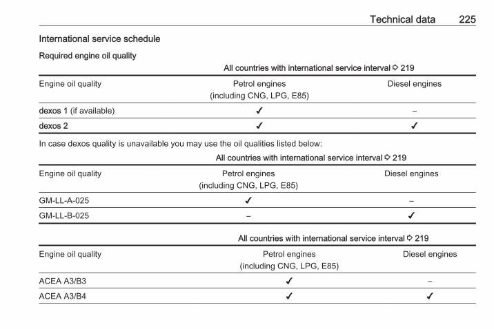
Technical data 225
International service schedule
Required engine oil qualityAll countries with international service interval 3 219
Engine oil quality Petrol engines(including CNG, LPG, E85)
Diesel engines
dexos 1 (if available) ✔ –
dexos 2 ✔ ✔
In case dexos quality is unavailable you may use the oil qualities listed below:
All countries with international service interval 3 219
Engine oil quality Petrol engines(including CNG, LPG, E85)
Diesel engines
GM-LL-A-025 ✔ –
GM-LL-B-025 – ✔
All countries with international service interval 3 219
Engine oil quality Petrol engines(including CNG, LPG, E85)
Diesel engines
ACEA A3/B3 ✔ –
ACEA A3/B4 ✔ ✔
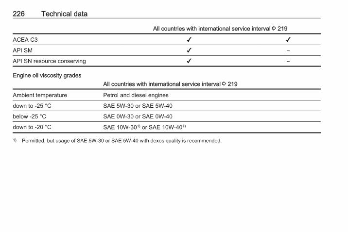
226 Technical data
All countries with international service interval 3 219
ACEA C3 ✔ ✔
API SM ✔ –
API SN resource conserving ✔ –
Engine oil viscosity gradesAll countries with international service interval 3 219
Ambient temperature Petrol and diesel engines
down to -25 °C SAE 5W-30 or SAE 5W-40
below -25 °C SAE 0W-30 or SAE 0W-40
down to -20 °C SAE 10W-301) or SAE 10W-401)
1) Permitted, but usage of SAE 5W-30 or SAE 5W-40 with dexos quality is recommended.

Technical data 227
Engine dataEngine identifier code B14XER B14NEL B14NEL B14NETSales designation 1.4 1.4 1.4 LPG 1.4Engineering code B14XER B14NEL B14NEL B14NET
Piston displacement [cm3] 1398 1364 1364 1364
Engine power [kW] 74 88 88 103
at rpm 6000 4200-6000 4800-6000 4900-6000
Torque [Nm] 130 175/2002) 175 200/2203)
at rpm 4000 1750-4800 1750-4800 1850-4900
Fuel type Petrol Petrol Liquid gas/Petrol Petrol
Octane rating RON4)
recommended 95 95 95 95
possible 98 98 98 98
possible 91 91 91 91
Additional fuel type – – Liquid gas (LPG) –
2) With six-speed transmission.3) With overboost function.4) A country specific label at the fuel filler flap can supersede the engine specific requirement.
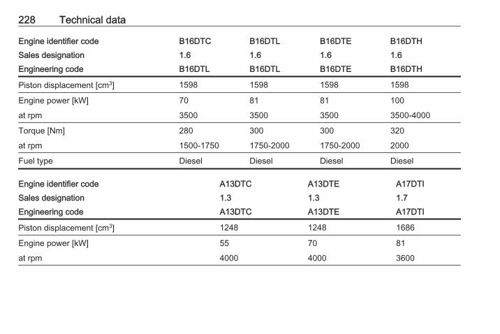
228 Technical data
Engine identifier code B16DTC B16DTL B16DTHB16DTESales designation 1.6 1.6 1.61.6Engineering code B16DTL B16DTL B16DTHB16DTE
Piston displacement [cm3] 1598 1598 15981598
Engine power [kW] 70 81 10081
at rpm 3500 3500 3500-40003500
Torque [Nm] 280 300 320300
at rpm 1500-1750 1750-2000 20001750-2000
Fuel type Diesel Diesel DieselDiesel
Engine identifier code A13DTC A13DTE A17DTISales designation 1.3 1.3 1.7Engineering code A13DTC A13DTE A17DTI
Piston displacement [cm3] 1248 1248 1686
Engine power [kW] 55 70 81
at rpm 4000 4000 3600
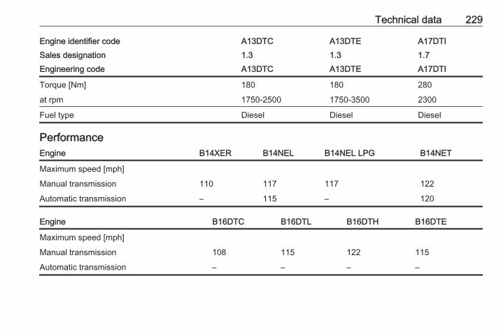
Technical data 229
Engine identifier code A13DTC A13DTE A17DTISales designation 1.3 1.3 1.7Engineering code A13DTC A13DTE A17DTI
Torque [Nm] 180 180 280
at rpm 1750-2500 1750-3500 2300
Fuel type Diesel Diesel Diesel
PerformanceEngine B14XER B14NEL B14NEL LPG B14NET
Maximum speed [mph]
Manual transmission 110 117 117 122
Automatic transmission – 115 – 120
Engine B16DTC B16DTL B16DTH B16DTE
Maximum speed [mph]
Manual transmission 108 115 122 115
Automatic transmission – – – –
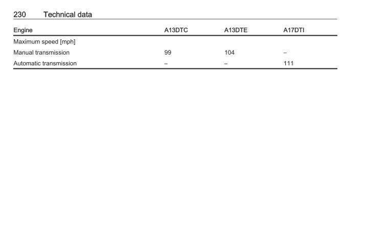
230 Technical data
Engine A13DTC A13DTE A17DTI
Maximum speed [mph]
Manual transmission 99 104 –
Automatic transmission – – 111
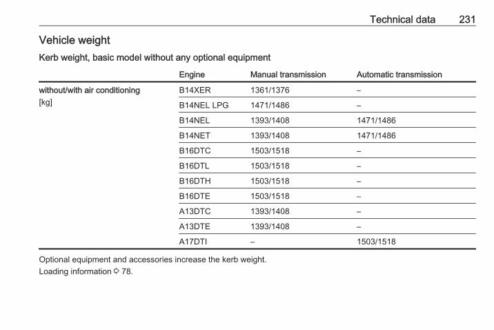
Technical data 231
Vehicle weightKerb weight, basic model without any optional equipment
Engine Manual transmission Automatic transmission
without/with air conditioning[kg]
B14XER 1361/1376 –
B14NEL LPG 1471/1486 –
B14NEL 1393/1408 1471/1486
B14NET 1393/1408 1471/1486
B16DTC 1503/1518 –
B16DTL 1503/1518 –
B16DTH 1503/1518 –
B16DTE 1503/1518 –
A13DTC 1393/1408 –
A13DTE 1393/1408 –
A17DTI – 1503/1518
Optional equipment and accessories increase the kerb weight.Loading information 3 78.
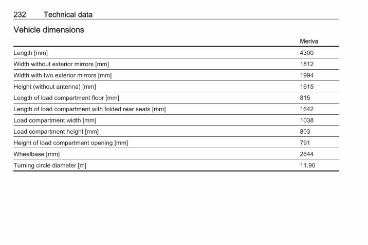
232 Technical data
Vehicle dimensionsMeriva
Length [mm] 4300
Width without exterior mirrors [mm] 1812
Width with two exterior mirrors [mm] 1994
Height (without antenna) [mm] 1615
Length of load compartment floor [mm] 815
Length of load compartment with folded rear seats [mm] 1642
Load compartment width [mm] 1038
Load compartment height [mm] 803
Height of load compartment opening [mm] 791
Wheelbase [mm] 2644
Turning circle diameter [m] 11.90

Technical data 233
CapacitiesEngine oil
Engine B14XER B14NEL B14NEL LPG B14NET A13DTC A13DTE
including Filter [l] 4.0 4.0 4.0 4.0 3.5 3.5
between MIN and MAX [l] 1.0 1.0 1.0 1.0 1.0 1.0
Engine B16DTC B16DTL B16DTH B16DTE A17DTI
including Filter [l] 5.0 5.0 5.0 5.0 5.4
between MIN and MAX [l] 1.0 1.0 1.0 1.0 1.0
Fuel tank
Petrol/diesel, refilling quantity [l] 54
LPG, refilling quantity [l] 34
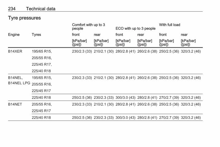
234 Technical data
Tyre pressuresComfort with up to 3people ECO with up to 3 people
With full load
Engine Tyres front rear front rear front rear[kPa/bar]([psi])
[kPa/bar]([psi])
[kPa/bar]([psi])
[kPa/bar]([psi])
[kPa/bar]([psi])
[kPa/bar]([psi])
B14XER 195/65 R15, 230/2.3 (33) 210/2.1 (30) 280/2.8 (41) 260/2.6 (38) 250/2.5 (36) 320/3.2 (46)
205/55 R16,
225/45 R17,
225/40 R18
B14NEL,B14NEL LPG
195/65 R15, 230/2.3 (33) 210/2.1 (30) 280/2.8 (41) 260/2.6 (38) 250/2.5 (36) 320/3.2 (46)
205/55 R16,
225/45 R17
225/40 R18 250/2.5 (36) 230/2.3 (33) 300/3.0 (43) 280/2.8 (41) 270/2.7 (39) 320/3.2 (46)
B14NET 205/55 R16, 230/2.3 (33) 210/2.1 (30) 280/2.8 (41) 260/2.6 (38) 250/2.5 (36) 320/3.2 (46)
225/45 R17
225/40 R18 250/2.5 (36) 230/2.3 (33) 300/3.0 (43) 280/2.8 (41) 270/2.7 (39) 320/3.2 (46)

Technical data 235
Comfort with up to 3people ECO with up to 3 people
With full load
Engine Tyres front rear front rear front rear[kPa/bar]([psi])
[kPa/bar]([psi])
[kPa/bar]([psi])
[kPa/bar]([psi])
[kPa/bar]([psi])
[kPa/bar]([psi])
A13DTC 195/65 R15, 230/2.3 (33) 210/2.1 (30) 280/2.8 (41) 260/2.6 (38) 250/2.5 (36) 320/3.2 (46)
205/55 R16,
225/45 R17,
225/40 R18
A13DTE 195/65 R15, 230/2.3 (33) 210/2.1 (30) 280/2.8 (41) 260/2.6 (38) 250/2.5 (36) 320/3.2 (46)
205/55 R16
B16DTC,B16DTL,B16DTH
205/55 R16, 250/2.5 (36) 230/2.3 (33) 300/3.0 (43) 280/2.8 (41) 270/2.7 (39) 320/3.2 (46)
225/45 R17
225/40 R18 270/2.7 (39) 250/2.5 (36) 300/3.0 (43) 280/2.8 (41) 280/2.8 (41) 320/3.2 (46)
B16DTE 205/55 R16 250/2.5 (36) 230/2.3 (33) 300/3.0 (43) 280/2.8 (41) 270/2.7 (39) 320/3.2 (46)
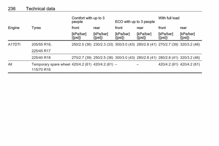
236 Technical data
Comfort with up to 3people ECO with up to 3 people
With full load
Engine Tyres front rear front rear front rear[kPa/bar]([psi])
[kPa/bar]([psi])
[kPa/bar]([psi])
[kPa/bar]([psi])
[kPa/bar]([psi])
[kPa/bar]([psi])
A17DTI 205/55 R16, 250/2.5 (36) 230/2.3 (33) 300/3.0 (43) 280/2.8 (41) 270/2.7 (39) 320/3.2 (46)
225/45 R17
225/40 R18 270/2.7 (39) 250/2.5 (36) 300/3.0 (43) 280/2.8 (41) 280/2.8 (41) 320/3.2 (46)
All Temporary spare wheel115/70 R16
420/4.2 (61) 420/4.2 (61) – – 420/4.2 (61) 420/4.2 (61)
Customer information 237
Customerinformation
Customer information ................ 237Declaration of conformity ......... 237Collision damage repair ........... 239Software acknowledgement .... 239
Vehicle data recording and pri‐vacy ........................................... 241
Event data recorders ............... 241Radio Frequency Identification(RFID) ..................................... 242
Customer informationDeclaration of conformityTransmission systemsThis vehicle has systems thattransmit and/or receive radio wavessubject to Directive 1999/5/EC.These systems are in compliancewith the essential requirements andother relevant provisions ofDirective 1999/5/EC. Copies of theoriginal Declarations of Conformitycan be obtained on our website.
238 Customer information
Jack

Customer information 239
Translation of the original declarationof conformityDeclaration of conformity accordingto EC Directive 2006/42/ECWe declare that the product:Product designation: JackType/GM part number: 13576735is in compliance with the provisions ofDirective 2006/42/EC.Applied technical standards:GMN9737 : jackingGM 14337 : standard equipment
jack – hardwaretests
GMN5127 : vehicle integrity –hoisting and servicestation jacking
GMW15005 : standard equipmentjack and spare tire,vehicle test
ISO TS 16949 : qualitymanagementsystems
The signatory is authorised tocompile the technical documentation.Rüsselsheim, 31st January 2014signed byHans-Peter MetzgerEngineering Group Manager Chassis& StructureAdam Opel AGD-65423 Rüsselsheim
Collision damage repairPaint thicknessDue to production techniques, thethickness of the paint can varybetween 50 and 400 µm.Therefore, different paint thickness isno indicator for a collision damagerepair.
Software acknowledgementCertain OnStar components includelibcurl and unzip software and otherthird party software. Below are thenotices and licenses associated withlibcurl and unzip and for other thirdparty software please see http://www.lg.com/global/support/opensource/index.
libcurlCopyright and permission noticeCopyright (c) 1996 - 2010, DanielStenberg, <[email protected]>.All rights reserved.Permission to use, copy, modify, anddistribute this software for anypurpose with or without fee is herebygranted, provided that the abovecopyright notice and this permissionnotice appear in all copies.The software is provided "as is",without warranty of any kind, expressor implied, including but not limited tothe warranties of merchantability,fitness for a particular purpose andnoninfringement of third party rights.In no event shall the authors or

240 Customer information
copyright holders be liable for anyclaim, damages or other liability,whether in an action of contract, tortor otherwise, arising from, out of or inconnection with the software or theuse or other dealings in the software.Except as contained in this notice, thename of a copyright holder shall notbe used in advertising or otherwise topromote the sale, use or otherdealings in this Software without priorwritten authorization of the copyrightholder.
unzipThis is version 2005-Feb-10 of theInfo-ZIP copyright and license. Thedefinitive version of this documentshould be available at ftp://ftp.info-zip.org/pub/infozip/license.htmlindefinitely.Copyright (c) 1990-2005 Info-ZIP. Allrights reserved.For the purposes of this copyright andlicense, “Info-ZIP” is defined as thefollowing set of individuals:Mark Adler, John Bush, Karl Davis,Harald Denker, Jean-Michel Dubois,Jean-loup Gailly, Hunter Goatley, Ed
Gordon, Ian Gorman, Chris Herborth,Dirk Haase, Greg Hartwig, RobertHeath, Jonathan Hudson, PaulKienitz, David Kirschbaum, JohnnyLee, Onno van der Linden, IgorMandrichenko, Steve P. Miller, SergioMonesi, Keith Owens, GeorgePetrov, Greg Roelofs, Kai UweRommel, Steve Salisbury, DaveSmith, Steven M. Schweda, ChristianSpieler, Cosmin Truta, AntoineVerheijen, Paul von Behren, RichWales, Mike White.This software is provided “as is,”without warranty of any kind, expressor implied. In no event shall Info-ZIPor its contributors be held liable forany direct, indirect, incidental, specialor consequential damages arising outof the use of or inability to use thissoftware.Permission is granted to anyone touse this software for any purpose,including commercial applications,and to alter it and redistribute it freely,subject to the following restrictions:
1. Redistributions of source codemust retain the above copyrightnotice, definition, disclaimer, andthis list of conditions.
2. Redistributions in binary form(compiled executables) mustreproduce the above copyrightnotice, definition, disclaimer, andthis list of conditions indocumentation and/or othermaterials provided with thedistribution. The sole exception tothis condition is redistribution of astandard UnZipSFX binary(including SFXWiz) as part of aself-extracting archive; that ispermitted without inclusion of thislicense, as long as the normalSFX banner has not beenremoved from the binary ordisabled.
3. Altered versions--including, butnot limited to, ports to newoperating systems, existing portswith new graphical interfaces, anddynamic, shared, or static libraryversions--must be plainly markedas such and must not bemisrepresented as being the
Customer information 241
original source. Such alteredversions also must not bemisrepresented as being Info-ZIPreleases--including, but notlimited to, labeling of the alteredversions with the names “Info-ZIP” (or any variation thereof,including, but not limited to,different capitalizations), “PocketUnZip,” “WiZ” or “MacZip” withoutthe explicit permission of Info-ZIP.Such altered versions are furtherprohibited from misrepresentativeuse of the Zip-Bugs or Info-ZIP e-mail addresses or of the Info-ZIPURL(s).
4. Info-ZIP retains the right to usethe names “Info-ZIP,” “Zip,”“UnZip,” “UnZipSFX,” “WiZ,”“Pocket UnZip,” “Pocket Zip,” and“MacZip” for its own source andbinary releases.
Vehicle data recordingand privacyEvent data recordersData storage modules in thevehicleA large number of electroniccomponents of your vehicle containdata storage modules temporarily orpermanently storing technical dataabout the condition of the vehicle,events and errors. In general, thistechnical information documents thecondition of parts, modules, systemsor the environment:● operating conditions of system
components (e.g. filling levels)● status messages of the vehicle
and its single components (e.g.number of wheel revolutions /rotational speed, deceleration,lateral acceleration)
● dysfunctions and defects inimportant system components
● vehicle reactions in particulardriving situations (e.g. inflation ofan airbag, activation of thestability regulation system)
● environmental conditions (e.g.temperature)
These data are exclusively technicaland help identifying and correctingerrors as well as optimising vehiclefunctions.Motion profiles indicating travelledroutes cannot be created with thesedata.If services are used (e.g. repairworks, service processes, warrantycases, quality assurance),employees of the service network(manufacturer included) are able toread out this technical informationfrom the event and error data storagemodules applying special diagnosticdevices. If required, you will receivefurther information at theseworkshops. After an error has beencorrected, the data are deleted fromthe error storage module or they areconstantly overwritten.

242 Customer information
When using the vehicle, situationsmay occur in which these technicaldata related to other information(accident report, damages on thevehicle, witness statements etc.) maybe associated with a specific person -possibly, with the assistance of anexpert.Additional functions contractuallyagreed upon with the client (e.g.vehicle location in emergency cases)allow the transmission of particularvehicle data from the vehicle.
Radio FrequencyIdentification (RFID)RFID technology is used in somevehicles for functions such as tyredeflation detection and ignitionsystem security. It is also used inconnection with conveniences suchas radio remote controls for doorlocking/unlocking and starting, and in-vehicle transmitters for garage dooropeners. RFID technology inVauxhall vehicles does not use orrecord personal information or linkwith any other Vauxhall systemcontaining personal information.

Customer information 243

244
Index AAccessories and vehicle
modifications .......................... 171Active head restraints .................. 35Adaptive brake light.................... 149Adaptive forward lighting .... 99,
122, 181Adjustable air vents ................... 135Airbag and belt tensioners ........... 94Airbag deactivation ................ 52, 94Airbag label................................... 48Airbag system .............................. 48Air conditioning regular
operation ................................ 136Air conditioning system .............. 129Air intake .................................... 136Air vents...................................... 135Alert............................................ 107Antifreeze................................... 174Antilock brake system ................ 149Antilock brake system (ABS) ....... 96Anti-theft alarm system ................ 27Anti-theft locking system .............. 27Appearance care........................ 215Armrest................................... 39, 42Armrest storage ........................... 62Ashtrays ....................................... 87Automatic anti-dazzle .................. 30Automatic light control ............... 120Automatic locking .................. 24, 99
Automatic transmission ............. 145Autostop..................................... 141Auxiliary heater .......................... 135
BBattery discharge protection ...... 127Battery voltage ........................... 108Belts.............................................. 44Bicycle rack.................................. 63Bonnet ....................................... 172Brake and clutch fluid................. 220Brake and clutch system ............. 95Brake assist ............................... 151Brake fluid .................................. 175Brakes ............................... 149, 175Breakdown.................................. 213Bulb replacement ....................... 179
CCapacities .................................. 233Car Pass ...................................... 20Catalytic converter ..................... 145Central locking system ................ 22Centre console lighting .............. 126Changing tyre and wheel size . . . 200Charging system .......................... 95Child locks ................................... 25Child restraint installation
locations ................................... 56Child restraints.............................. 54Child restraint systems ................ 54
245
Cigarette lighter ........................... 87Climate control ............................. 15Climate control, service.............. 136Climate control systems............. 128Clock............................................. 85Code........................................... 105Collision damage repair.............. 239Control indicators.......................... 91Control of the vehicle ................. 138Controls........................................ 81Controls in steering wheel............ 81Convex shape .............................. 29Coolant....................................... 174Coolant and antifreeze............... 220Coolant temperature gauge.......... 89Coupling ball bar........................ 167Cruise control ...................... 99, 153Cupholders .................................. 60Curtain airbag system .................. 52Curve lighting.............................. 122
DDanger, Warnings and Cautions . . . 4Dashboard.................................... 10Daytime running light.................. 120Daytime running lights ............... 122Declaration of conformity............ 237Diesel fuel system bleeding ....... 178Diesel particle filter............... 97, 144Door open .................................... 99
Doors............................................ 26Driver assistance systems.......... 153Driver Information Centre........... 100Driving characteristics and
towing tips .............................. 166Driving hints................................ 138
EElectric adjustment ...................... 29Electrical system......................... 188Electric parking brake........... 96, 150Electric parking brake fault........... 96Electronic climate control system 131Electronic driving programmes . . 147Electronic Stability Control.......... 152Electronic Stability Control and
Traction Control system ........... 97Electronic Stability Control off ...... 97End-of-life vehicle recovery ....... 171Engine compartment fuse box ... 190Engine coolant ........................... 174Engine coolant temperature
gauge ....................................... 89Engine data ............................... 227Engine exhaust .......................... 144Engine identification................... 223Engine oil ................... 173, 220, 224Engine oil pressure ...................... 98Entry lighting .............................. 126Event data recorders.................. 241
Exhaust gases............................ 144Exit lighting ................................ 126Exterior care .............................. 215Exterior light ................................. 98Exterior lighting .................... 12, 119Exterior mirrors............................. 29
FFault ........................................... 147First aid......................................... 77First aid kit ................................... 77Fixed air vents ........................... 136Flex-Fix system............................ 63Fog light ....................................... 99Fog lights.................... 123, 124, 183Folding mirrors ............................. 29Folding tray .................................. 77Front airbag system ..................... 51Front fog lights ........................... 123Front seats.................................... 36Front storage ............................... 62Front turn signal light.................. 179Front turn signal lights ............... 183Fuel............................................. 159Fuel consumption - CO2-
Emissions ............................... 164Fuel for diesel engines .............. 159Fuel for liquid gas operation....... 159Fuel for petrol engines ............... 159Fuel gauge ................................... 89
246
Fuel selector ................................ 89Fuse box..................................... 190Fuses ......................................... 188
GGauges......................................... 88General information ................... 165Glovebox ..................................... 60Graphic-Info-Display, Colour-
Info-Display ............................ 103
HHalogen headlights .................... 179Hand brake......................... 149, 150Hazard warning flashers ............ 123Headlight flash ........................... 121Headlight range adjustment ...... 121Headlights.......................... 119, 121Headlights when driving abroad 121Head restraint adjustment ............. 8Head restraints ............................ 34Heated mirrors ............................. 29Heated rear window ..................... 32Heated steering wheel ................. 81Heating ........................................ 40Heating and ventilation system . 128High beam ........................... 99, 121Hill start assist ........................... 151Horn ....................................... 13, 82
IIdentification plate ..................... 223Ignition switch positions ............. 139Immobiliser ............................ 28, 98Indicators...................................... 88Information displays.................... 100Instrument cluster ........................ 88Instrument panel fuse box ......... 192Instrument panel illumination ..... 188Instrument panel illumination
control .................................... 125Instrument panel overview ........... 10Interior care ............................... 217Interior lighting............................ 125Interior lights ...................... 125, 188Interior mirrors.............................. 30Interruption of power supply ...... 147Introduction .................................... 3ISOFIX child restraint systems .... 59
JJump starting ............................. 212
KKeys ............................................. 19Keys, locks................................... 19Keys, memorised settings............ 21
LLashing eyes ............................... 75Light covers, misted.................... 124
Lighting features......................... 126Light switch ................................ 119Load compartment ................ 26, 72Load compartment cover ............. 73Load compartment fuse box ...... 193Loading information ..................... 78Low fuel ....................................... 98
MMalfunction indicator light ............ 95Manual anti-dazzle ...................... 30Manual mode ............................. 147Manual transmission .................. 148Manual windows .......................... 31Memorised settings...................... 21Midlevel-Display......................... 100Mirror adjustment ........................... 8Misted light covers ..................... 124Moonroof ..................................... 33
NNew vehicle running-in .............. 139Number plate light ..................... 187
OObject detection systems........... 155Octane rating.............................. 227Odometer ..................................... 88Oil............................................... 173Oil, engine.......................... 220, 224Oil pressure.................................. 98
247
OnStar........................................ 115Operate pedal............................... 95Outside temperature .................... 84Overrun cut-off ........................... 141
PParking ................................ 17, 143Parking assist ............................ 155Parking brake ............................ 150Parking lights ............................. 124Particulate filter........................... 144Performance .............................. 229Performing work ........................ 172Personalisation........................... 111Pollen filter ................................. 136Power outlets ............................... 86Power steering fluid.................... 175Power windows ............................ 31Preheating ................................... 97Puncture..................................... 206
QQuickheat................................... 135
RRadio Frequency Identification
(RFID)..................................... 242Radio remote control ................... 20Reading lights ............................ 126Rear carrier system...................... 63Rear doors ................................... 26
Rear floor storage cover .............. 74Rear fog light ............................... 99Rear fog lights ........................... 124Rear seats.................................... 41Rear storage................................. 73Rear view camera ...................... 157Rear window wiper/washer .......... 84Recommended fluids and
lubricants ........................ 220, 224Reduced engine power ............... 98Refuelling ................................... 161Remote control............................. 20Retained power off..................... 139Reversing lights ......................... 124Ride control systems.................. 152Roof.............................................. 33Roof load...................................... 78Roof rack ..................................... 78
SSafety belts................................... 44Safety net .................................... 75Seat adjustment ....................... 6, 37Seat belt ........................................ 8Seat belt reminder ....................... 94Seat belts ..................................... 44Seat heating................................. 40Seat position ................................ 36Selector lever ............................. 146Service ............................... 136, 219
Service display ............................ 90Service information .................... 219Service vehicle soon .................... 95Side airbag system ...................... 51Sidelights.................................... 119Side turn signal lights ................ 187Software acknowledgement....... 239Spare wheel ............................... 209Speedometer ............................... 88Starting and operating................ 139Starting off ................................... 16Starting the engine .................... 140Steering...................................... 139Steering wheel adjustment ...... 9, 81Steering wheel controls ............... 81Steering wheel, heated................. 81Stop-start system........................ 141Storage......................................... 60Storage compartments................. 60Sunvisor lights ........................... 126Sun visors .................................... 33Symbols ......................................... 4
TTachometer ................................. 88Tailgate......................................... 26Tail lights ................................... 184Technical data............................ 227Three-point seat belt .................... 45Tools .......................................... 194
248
Top-tether fastening eyes ............ 59Tow bar....................................... 165Towing................................ 165, 213Towing another vehicle ............. 214Towing a trailer........................... 166Towing equipment ..................... 167Towing the vehicle ..................... 213Traction Control system ............. 152Traction Control system off .......... 97Trailer coupling........................... 165Trailer towing ............................. 166Transmission ............................... 16Transmission display ................. 145Tread depth ............................... 200Trip computer ............................ 108Trip odometer .............................. 88Tunnel detection......................... 120Turn and lane-change signals ... 123Turn signal ................................... 93Tyre chains ................................ 201Tyre designations ...................... 195Tyre pressure ............................ 196Tyre pressure monitoring
system............................... 97, 197Tyre pressures ........................... 234Tyre repair kit ............................. 201Tyres and wheel size, changing. 200
UUltrasonic parking assist ...... 96, 155Underseat storage ....................... 62Upholstery.................................. 217Uplevel-Combi-Display............... 100Uplevel-Display........................... 100Upshift.......................................... 96Using this manual .......................... 3
VVariable effort steering................. 96Vehicle battery ........................... 176Vehicle battery, jump starting..... 212Vehicle checks............................ 172Vehicle data................................ 224Vehicle data recording and
privacy..................................... 241Vehicle dimensions .................... 232Vehicle Identification Number .... 222Vehicle jack................................ 194Vehicle messages ..................... 105Vehicle personalisation ............. 111Vehicle security............................ 27Vehicle specific data ...................... 3Vehicle storage........................... 171Vehicle tools............................... 194Vehicle unlocking ........................... 6Vehicle weight ........................... 231Ventilation................................... 128
WWarning chimes ......................... 107Warning lights............................... 88Warning triangle .......................... 77Washer and wiper systems ......... 14Washer fluid ............................... 175Welcome lighting........................ 126Wheel changing ......................... 206Wheel covers ............................. 201Wheels and tyres ....................... 195Windows....................................... 30Windscreen................................... 30Windscreen wiper/washer ........... 82Winter tyres ............................... 195Wiper blade replacement .......... 178

Copyright by General Motors UK Ltd.
The information contained in this publication is effective as of the date indicated below. General Motors UK Ltd. reserves the rightto make changes to the technical specifications, features and design of the vehicles relative to the information contained in thispublication, as well as changes to the publication itself.
Edition: January 2016, General Motors UK Ltd.
Printed on chlorine-free bleached paper.
*KTA-2690/11-VX-EN*
KTA-2690/11-VX-en 01/2016


