82
Ventilation Accessories We reserve the right to make changes in the dimensions and technical data products due to their continuous improvement

Ventilation Accessories
We reserve the right to make changes in the dimensions and technical data products due to their continuous improvement

Vent
ilati
on A
cces
sori
es
ALNOR® ventilation systemsis a legally protected trademark and technical patent. All rights reserved.
Download WentyleDownload AlnorCAM
Buy via B2B
About the SystemALNOR accessories consist of a complete range of components to finish ventilation systems, such as grilles, nozzles, air diffusers, ventilation valves and plenum boxes.
Dimensions Most the products can be connected to standard round ducts. It can be made directly or through plenum boxes intended for this purposes. The remaining values are based on the tables and information provided in a product’s catalogue datasheet.
About the System
Installation GuideInstallation depends on the type of products employed. In most cases this information results from the installation system of ventilation ducts.
Benefits of UseAn attractive appearance combined with the easy installation of components helps finish a duct system efficiently. Flow rates can be customised to adapt the volume of air delivered to rooms.
LabellingALNOR products are furnished with the construction industry’s B sign and product codes according to their technical specifications contained in this catalogue.
Ventilation Accessories
ALNOR® ventilation systemsis a legally protected trademark and technical patent. All rights reserved.
Download WentyleDownload AlnorCAM
Buy via B2B
Dimensions
Description
Roof Valves
KW
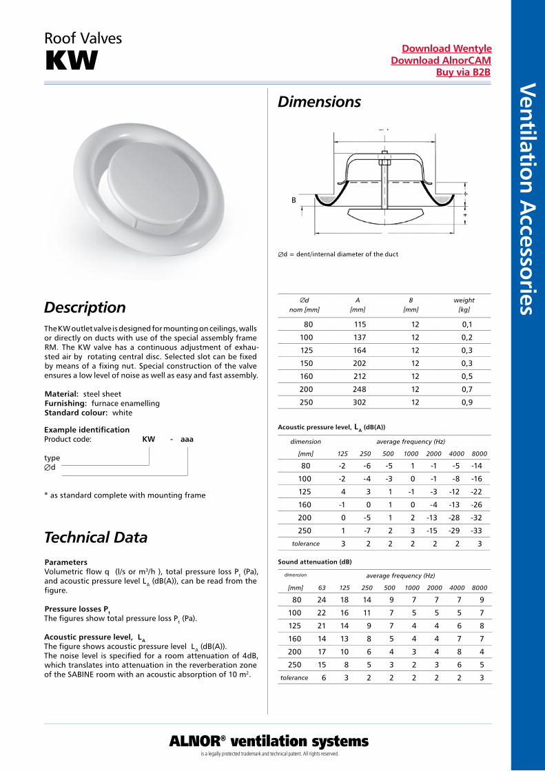
The KW outlet valve is designed for mounting on ceilings, walls or directly on ducts with use of the special assembly frame RM. The KW valve has a continuous adjustment of exhau-sted air by rotating central disc. Selected slot can be fixed by means of a fixing nut. Special construction of the valve ensures a low level of noise as well as easy and fast assembly.
Material: steel sheetFurnishing: furnace enamellingStandard colour: white
Example identificationProduct code: KW - aaa
typeÆd
* as standard complete with mounting frame
Parameters Volumetric flow q (l/s or m3/h ), total pressure loss Pt (Pa), and acoustic pressure level LA (dB(A)), can be read from the figure.
Pressure losses Pt The figures show total pressure loss Pt (Pa).
Acoustic pressure level, LA The figure shows acoustic pressure level LA (dB(A)).The noise level is specified for a room attenuation of 4dB, which translates into attenuation in the reverberation zone of the SABINE room with an acoustic absorption of 10 m2.
Æd = dent/internal diameter of the duct
dnom [mm]
A[mm]
B[mm]
weight[kg]
Acoustic pressure level, LA (dB(A))
Sound attenuation (dB)
dimension average frequency (Hz)
[mm] 125 250 500 1000 2000 4000 8000
dimension average frequency (Hz)
[mm] 63 125 250 500 1000 2000 4000 8000
Technical Data
Æd
A
B
80 115 12 0,1
100 137 12 0,2
125 164 12 0,3
150 202 12 0,3
160 212 12 0,5
200 248 12 0,7
250 302 12 0,9
80 -2 -6 -5 1 -1 -5 -14
100 -2 -4 -3 0 -1 -8 -16
125 4 3 1 -1 -3 -12 -22
160 -1 0 1 0 -4 -13 -26
200 0 -5 1 2 -13 -28 -32
250 1 -7 2 3 -15 -29 -33
tolerance 3 2 2 2 2 2 3
80 24 18 14 9 7 7 7 9
100 22 16 11 7 5 5 5 7
125 21 14 9 7 4 4 6 8
160 14 13 8 5 4 4 7 7
200 17 10 6 4 3 4 8 4
250 15 8 5 3 2 3 6 5
tolerance 6 3 2 2 2 2 2 3

Vent
ilati
on A
cces
sori
es
ALNOR® ventilation systemsis a legally protected trademark and technical patent. All rights reserved.
Download WentyleDownload AlnorCAM
Buy via B2B
Example identificationProduct code: KWI - aaa
typeÆd
* as standard without mounting frame included
Description
Dimensions
Parameters Volumetric flow q (l/s or m3/h ), total pressure loss Pt (Pa), and acoustic pressure level LA (dB(A)), can be read from the figure.
Pressure losses Pt The figures show total pressure loss Pt (Pa).
Acoustic pressure level, LA The figure shows acoustic pressure level LA (dB(A)).The noise level is specified for a room attenuation of 4dB, which translates into attenuation in the reverberation zone of the SABINE room with an acoustic absorption of 10 m2.
Insulated exhaust valves
KWI
The KWI outlet valve is designed for mounting on ceilings, walls or directly on ducts with use of the special assembly frame RM.The KWI valve has a continuous adjustment of exhau-sted air by rotating central disc. Selected slot can be fixed by means of a fixing nut. Special construction of the valve ensures a low level of noise as well as easy and fast assembly. .
Material: galvanized steel sheetFinishing: glossy powder painted acc. to RAL 9016Standard colour: white
Technical Data
Acoustic pressure level, LA (dB(A))
Sound attenuation (dB)
Dnom [mm]
A[mm]
B[mm]
weight[kg]
dimension average frequency (Hz)
[mm] 125 250 500 1000 2000 4000 8000
dimension average frequency (Hz)
[mm] 63 125 250 500 1000 2000 4000 8000
80 108 16 0,1
100 137 16 0,2
125 162 16 0,3
160 193 16 0,5
200 240 19 0,7
80 -2 -6 -5 1 -1 -5 -14
100 -2 -4 -3 0 -1 -8 -16
125 4 3 1 -1 -3 -12 -22
160 -1 0 1 0 -4 -13 -26
200 0 -5 1 2 -13 -28 -32
tolerance 3 2 2 2 2 2 3
80 24 18 14 9 7 7 7 9
100 22 16 11 7 5 5 5 7
125 21 14 9 7 4 4 6 8
160 14 13 8 5 4 4 7 7
200 17 10 6 4 3 4 8 4
tolerance 6 3 2 2 2 2 2 3

Ventilation Accessories
ALNOR® ventilation systemsis a legally protected trademark and technical patent. All rights reserved.
Download WentyleDownload AlnorCAM
Buy via B2B
Dimensions
Description
Example identificationProduct code: KW-S - aaa
typeÆd
* as standard complete with mounting frame
Technical DataParameters Volumetric flow q (l/s or m3/h ), total pressure loss Pt (Pa), and acoustic pressure level LA (dB(A)), can be read from the figure.
Pressure losses Pt The figures show total pressure loss Pt (Pa).
Acoustic pressure level, LA The figure shows acoustic pressure level LA (dB(A)).The noise level is specified for a room attenuation of 4dB, which translates into attenuation in the reverberation zone of the SABINE room with an acoustic absorption of 10 m2.
Chromium plated exhaust valves
KW-S
Dnom [mm]
A[mm]
B[mm]
weight[kg]
Acoustic pressure level, LA (dB(A))
Sound attenuation (dB)
dimension average frequency (Hz)
[mm] 125 250 500 1000 2000 4000 8000
dimension average frequency (Hz)
[mm] 63 125 250 500 1000 2000 4000 8000
The KW-S-RM outlet valve is designed for mounting on ceilings, walls or directly on ducts with use of the special assembly frame RM.The KW-S-RM valve has a continuous adjustment of rotating central disc. Selected slot can be fixed by means of a fixing nut. Special construction of the valve ensures a low level of noise as well as easy and fast assembly.
Material: galvanized steel sheet Finishing: chromium plated
80 115 12 0,15
100 137 12 0,19
125 164 12 0,31
150 202 12 0,35
160 212 12 0,47
200 248 12 0,66
80 -2 -6 -5 1 -1 -5 -14
100 4 3 2 0 -7 -15 -30
125 2 7 3 -2 -10 -20 -32
150 3 7 3 -2 -10 -20 -32
160 5 7 3 -2 -10 -19 -32
200 8 6 4 -3 -10 -19 -32
tolerance 3 2 2 2 2 2 3
80 26 18 14 10 8 8 6 9
100 22 16 11 8 6 6 3 6
125 20 15 9 6 4 3 3 5
150 19 15 9 6 4 3 4 5
160 18 13 8 5 4 4 5 6
200 17 11 7 6 6 5 6 6
tolerance 6 3 2 2 2 2 2 3
D

Vent
ilati
on A
cces
sori
es
ALNOR® ventilation systemsis a legally protected trademark and technical patent. All rights reserved.
Download WentyleDownload AlnorCAM
Buy via B2B
Parameters Volumetric flow q (l/s or m3/h ), total pressure loss Pt (Pa), and acoustic pressure level LA (dB(A)), can be read from the figure.
Pressure losses Pt The figures show total pressure loss Pt (Pa).
Acoustic pressure level, LA The figure shows acoustic pressure level LA (dB(A)).The noise level is specified for a room attenuation of 4dB, which translates into attenuation in the reverberation zone of the SABINE room with an acoustic absorption of 10 m2.
Dimensions
Description
Exhaust valves
KWO
The KWO outlet valve is designed for mounting on ceilings, walls or directly on ducts with use of the special assembly frame RML.The KWO valve has a continuous adjustment of rotating central disc. Selected slot can be fixed by means of a fixing nut. Special construction of the valve ensures a low level of noise as well as easy and fast assembly.
Material: galvanized steel sheetFinishing: glossy powder painted acc. to RAL 9016Standard colour: white
Example identificationProduct code: KWO - aaa
typed
* as standard complete with mounting frame
Technical Data
Acoustic pressure level, LA (dB(A))
Sound attenuation (dB)
Dnom [mm]
A[mm]
weight[kg]
dimension average frequency (Hz)
[mm] 125 250 500 1000 2000 4000 8000
dimension average frequency (Hz)
[mm] 63 125 250 500 1000 2000 4000 8000
100 130 0,3
125 160 0,4
160 190 0,5
200 235 0,8
100 -6 -3 -3 -4 -9 -13 -27
125 -7 -6 -5 -8 -4 -12 -28
160 -3 -7 -5 -2 -12 -16 -29
200 -5 -7 -8 -2 -9 -13 -30
tolerance 3 2 2 2 2 2 3
100 23 18 14 12 12 14 5 6
125 21 17 12 11 12 11 7 6
160 19 14 12 11 11 14 5 7
200 15 13 11 11 13 12 7 7
tolerance 6 3 2 2 2 2 2 3
ØD
Ød

Ventilation Accessories
ALNOR® ventilation systemsis a legally protected trademark and technical patent. All rights reserved.
Download WentyleDownload AlnorCAM
Buy via B2B
Roof Valves
KW, KWI, KW-STechnical DataSelection charts
float [m3/h]
location [mm]
pre
ssur
e lo
ss P
t [P
a]
float [m3/h]
float [m3/h]
float [m3/h]
float [m3/h]
float [m3/h]
location [mm]
pre
ssur
e lo
ss P
t [P
a]
location [mm]
pre
ssur
e lo
ss P
t [P
a]
location [mm]
pre
ssur
e lo
ss P
t [P
a]
location [mm]
pre
ssur
e lo
ss P
t [P
a]
location [mm]
pre
ssur
e lo
ss P
t [P
a]
location [mm]
pre
ssur
e lo
ss P
t [P
a]
float [m3/h]
-12 -6 0 6 12
250

Vent
ilati
on A
cces
sori
es
ALNOR® ventilation systemsis a legally protected trademark and technical patent. All rights reserved.
Download WentyleDownload AlnorCAM
Buy via B2B
Exhaust valves
KWOTechnical DataSelection charts
float
location
stra
ta c
iśni
enia
Pt
[Pa]
float
location
stra
ta c
iśni
enia
Pt
[Pa]
float
location
stra
ta c
iśni
enia
Pt
[Pa]
float
location
stra
ta c
iśni
enia
Pt
[Pa]
pre
ssur
e lo
ccp
ress
ure
locc
pre
ssur
e lo
ccp
ress
ure
locc
2
3
7
9
10
11
14
15
16
10
20
50
100
5 10 20 50 [l/s]
∆ p
t [Pa
]
20
q
50 100 180 [m3/h]
Ø 100
200
30 40
a [mm]
30
35
40
-15 -12 -10 -5 0 5
10
L WA [dB(A)]
2
3
7
9
10
11
14
15
16
10
20
50
100
5 10 20 80 [l/s]
∆ p t [
Pa]
20
q
50 100 200 [m3/h]
Ø 125200
30 40 50
a [mm]
30
35
40
-10 -5 0 5 10
LWA [dB(A)]
2
3
7
9
10
11
14
15
16
10
20
50
100
10 15 20 130 [l/s]
∆ p
t [Pa
]
40
q
100 200 300 [m3/h]
Ø 160200
30 40 50
400
100
a [mm]
30
35
40
-10 -5 0 5 10 15
L WA [dB(A)]
2
3
4
5
7
8
9
11
13
15
10
20
50
100
20 30 40 150 [l/s]
∆ p t [
Pa]
80
q
150 200 300 [m3/h]
Ø 200200
50 100
400
200
100 500
a [mm]
30
35
40
-3 0 5 10 15 20 25
L WA [dB(A)]

Ventilation Accessories
ALNOR® ventilation systemsis a legally protected trademark and technical patent. All rights reserved.
Download WentyleDownload AlnorCAM
Buy via B2B
Dimensions
Description
Supply Air Valves
KN
The KNI air supply valve is designed for mounting on ceilings, walls or directly on ducts with use of the special assembly frame RM. The KNI valve has a continuous adjustment of inlet air by rotating central disc. Selected slot can be fixed by means of a fixing nut. Special construction of the valve ensures a low level of noise as well as easy and fast assembly.
Material: steel sheetFurnishing: furnace enamellingStandard colour: white
Example identificationProduct code: KN - aaa
typeÆd
* as standard complete with mounting frame
Parameters Volumetric flow q (l/s or m3/h.), total pressure loss Pt(Pa) and acoustic pressure level LA (dB(A)) for various cone settings can be read from the figure.
Pressure losses Pt The figures show total pressure loss Pt (Pa).
Acoustic pressure level, LA The figure shows acoustic pressure level LA (dB(A)).The noise level is specified for a room attenuation of 4dB, which translates into attenuation in the reverberation zone of the SABINE room with an acoustic absorption of 10 m2
Control Details of how to control volumetric flow are to be found in the instructions for use.
dnom [mm]
A[mm]
B[mm]
weight[kg]
Acoustic pressure level LA (dB(A))
Sound attenuation (dB)
dimension average frequency (Hz)
[mm] 125 250 500 1000 2000 4000 8000
dimension average frequency (Hz)
[mm] 63 125 250 500 1000 2000 4000 8000
Technical Data
80 115 12 0,15
100 137 12 0,19
125 164 12 0,31
150 202 12 0,35
160 212 12 0,47
200 248 12 0,66
250 302 12 0,88
80 6 3 2 1 -4 -16 -20
100 4 3 2 0 -7 -15 -30
125 2 7 3 -2 -10 -20 -32
160 5 7 3 -2 -10 -19 -32
200 8 6 4 -3 -10 -19 -32
250 9 8 6 -4 -12 -20 -33
tolerance 3 2 2 2 2 2 3
80 22 19 14 11 2 3 7 8
100 22 16 11 8 6 6 3 6
125 20 15 9 6 4 3 3 5
160 18 13 8 5 4 4 5 6
200 17 11 7 6 6 5 6 6
250 18 12 9 7 7 6 7 5
tolerance 6 3 2 2 2 2 2 3
d
A
B

Vent
ilati
on A
cces
sori
es
ALNOR® ventilation systemsis a legally protected trademark and technical patent. All rights reserved.
Download WentyleDownload AlnorCAM
Buy via B2B
Dimensions
Description
Parameters Volumetric flow q (l/s or m3/h ), total pressure loss Pt (Pa), and acoustic pressure level LA (dB(A)), can be read from the figure.
Pressure losses Pt The figures show total pressure loss Pt (Pa).
Acoustic pressure level, LA The figure shows acoustic pressure level LA (dB(A)).The noise level is specified for a room attenuation of 4dB, which translates into attenuation in the reverberation zone of the SABINE room with an acoustic absorption of 10 m2.
Technical Data
Example identificationProduct code: KNI - aaa
typeÆd
* as standard complete with mounting frame
Insulated air supply valves
KNI
Dnom [mm]
A[mm]
Hmax
[mm]weight
[kg]
Acoustic pressure level, LA (dB(A))
Sound attenuation (dB)
dimension average frequency (Hz)
[mm] 125 250 500 1000 2000 4000 8000
dimension average frequency (Hz)
[mm] 63 125 250 500 1000 2000 4000 8000
The KNI air supply valve is designed for mounting on ceilings, walls or directly on ducts with use of the special assembly frame RM. The KNI valve has a continuous adjustment of inlet air by rotating central disc. Selected slot can be fixed by means of a fixing nut. Special construction of the valve ensures a low level of noise as well as easy and fast assembly.
Material: galvanized steel sheet Finishing: glossy powder painted acc. to RAL 9016 Standard colour: white
80 115 45 0,19
100 137 45 0,26
125 164 45 0,33
160 212 45 0,48
200 248 45 0,65
80 6 3 2 1 -4 -16 -20
100 4 3 2 0 -7 -15 -30
125 2 7 3 -2 -10 -20 -32
160 5 7 3 -2 -10 -19 -32
200 8 6 4 -3 -10 -19 -32
tolerance 3 2 2 2 2 2 3
80 22 19 14 11 2 3 7 8
100 22 16 11 8 6 6 3 6
125 20 15 9 6 4 3 3 5
160 18 13 8 5 4 4 5 6
200 17 11 7 6 6 5 6 6
tolerance 6 3 2 2 2 2 2 3
D
max

Ventilation Accessories
ALNOR® ventilation systemsis a legally protected trademark and technical patent. All rights reserved.
Download WentyleDownload AlnorCAM
Buy via B2B
Dimensions
Description
Example identificationProduct code: KN-S-RM - aaa
typeÆd
Parameters Volumetric flow q (l/s or m3/h.), total pressure loss Pt(Pa) and acoustic pressure level LA (dB(A)) for various cone set-tings can be read from the figure.
Pressure losses Pt The figures show total pressure loss Pt (Pa).
Acoustic pressure level, LA The figure shows acoustic pressure level LA (dB(A)).The noise level is specified for a room attenuation of 4dB, which translates into attenuation in the reverberation zone of the SABINE room with an acoustic absorption of 10 m2
Control Details of how to control volumetric flow are to be found in the instructions for use.
Chromium plated air supply valves
KN-S
Technical Data
Dnom [mm]
A[mm]
B[mm]
weight[kg]
Acoustic pressure level LA (dB(A))
Sound attenuation (dB)
dimension average frequency (Hz)
[mm] 125 250 500 1000 2000 4000 8000
dimension average frequency (Hz)
[mm] 63 125 250 500 1000 2000 4000 8000
The KN-S-RM air supply valve is designed for mounting on ceilings, walls or directly on ducts with use of the special assembly frame RM. The KN-S-RM has a continuous adjust-ment of rotating central disc. Selected slot can be fixed by means of a fixing nut. Special construction of the valve ensu-res a low level of noise as well as easy and fast assembly.
Material: galvanized steel sheetFinishing: chromium plated
80 115 12 0,15
100 137 12 0,19
125 164 12 0,31
150 202 12 0,35
160 212 12 0,47
200 248 12 0,66
80 6 4 3 -1 -5 -10 -27
100 4 3 2 0 -7 -15 -30
125 2 7 3 -2 -10 -20 -32
160 3 7 3 -2 -10 -21 -32
160 5 7 3 -2 -10 -19 -32
200 8 6 4 -3 -10 -19 -32
tolerance 3 2 2 2 2 2 3
80 21 13 11 9 7 7 4 6
100 22 16 11 8 6 6 3 6
125 20 15 9 6 4 3 3 5
150 19 14 8 6 4 3 3 6
160 18 13 8 5 4 4 5 6
200 17 11 7 6 6 5 6 6
tolerance 6 3 2 2 2 2 2 3
ØD
ØA
B

Vent
ilati
on A
cces
sori
es
ALNOR® ventilation systemsis a legally protected trademark and technical patent. All rights reserved.
Download WentyleDownload AlnorCAM
Buy via B2B
Parameters Volumetric flow q (l/s or m3/h.), total pressure loss Pt(Pa) and acoustic pressure level LA (dB(A)) for various cone set-tings can be read from the figure.
Pressure losses Pt The figures show total pressure loss Pt (Pa).
Acoustic pressure level, LA The figure shows acoustic pressure level LA (dB(A)).The noise level is specified for a room attenuation of 4dB, which translates into attenuation in the reverberation zone of the SABINE room with an acoustic absorption of 10 m2
Control Details of how to control volumetric flow are to be found in the instructions for use.
Dimensions
Description
Supply Air Valves
KNT
The KNI air supply valve is designed for mounting on ceilings, walls or directly on ducts with use of the special assembly frame RM. The KNI has a continuous adjustment of rotating central disc. Selected slot can be fixed by means of a fixing nut. Special construction of the valve ensures a low level of noise as well as easy and fast assembly.
Material: galvanized steel sheet Finishing: glossy powder painted acc. to RAL 9016Standard colour: white
Example identificationProduct code: KNT - aaa
typed
Technical Data
Acoustic pressure level LA (dB(A))
Sound attenuation (dB)
dimension average frequency (Hz)
[mm] 125 250 500 1000 2000 4000 8000
dimension average frequency (Hz)
[mm] 63 125 250 500 1000 2000 4000 8000
dnom [mm]
D[mm]
weight[kg]
100 -6 -2 -3 -5 -8 -9 -15
125 0 1 -1 -5 -15 -21 -33
160 3 2 -1 -6 -15 -23 -36
tolerance 3 2 2 2 2 2 3
100 22 18 13 11 9 8 7 8
125 20 16 11 9 9 7 6 5
160 18 14 10 9 9 7 6 6
tolerance 6 3 2 2 2 2 2 3
100 135 0,28
125 165 0,44
160 205 0,62
ØD
Ød

Ventilation Accessories
ALNOR® ventilation systemsis a legally protected trademark and technical patent. All rights reserved.
Download WentyleDownload AlnorCAM
Buy via B2B
Roof Valves
KN, KN-STechnical DataSelection charts
float [m3/h]
location [mm]
pre
ssur
e lo
ss P
t [P
a]
float [m3/h]
location [mm]
pre
ssur
e lo
ss P
t [P
a]
float [m3/h]
location [mm]
pre
ssur
e lo
ss P
t [P
a]
float [m3/h]
location [mm]
pre
ssur
e lo
ss P
t [P
a]
float [m3/h]
location [mm]
pre
ssur
e lo
ss P
t [P
a]
float [m3/h]
location [mm]
pre
ssur
e lo
ss P
t [P
a]
float [m3/h]
location [mm]
pre
ssur
e lo
ss P
t [P
a]
250

Vent
ilati
on A
cces
sori
es
ALNOR® ventilation systemsis a legally protected trademark and technical patent. All rights reserved.
Download WentyleDownload AlnorCAM
Buy via B2B
Technical DataSelection charts
float
location [mm]
pre
ssur
e lo
ss P
t [P
a]
float
location [mm]
pre
ssur
e lo
ss P
t [P
a]
float
location [mm]
pre
ssur
e lo
ss P
t [P
a]
float
location [mm]
pre
ssur
e lo
ss P
t [P
a]
float
location [mm]
pre
ssur
e lo
ss P
t [P
a]qv [l/s]
qv [m3/h]
qv [l/s]
qv [m3/h]
qv [l/s]
qv [m3/h]
qv [l/s]
qv [m3/h]
qv [l/s]
qv [m3/h]
10 20
110 20
30
5
15
5
10
10 2030
Insulated air supply valves
KNI
Ventilation Accessories
ALNOR® ventilation systemsis a legally protected trademark and technical patent. All rights reserved.
Download WentyleDownload AlnorCAM
Buy via B2B
Supply Air Valves
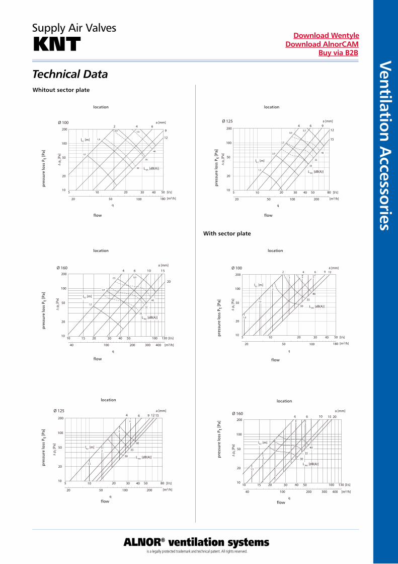
KNTTechnical DataWhitout sector plate
flow
location
pre
ssur
e lo
ss P
t [P
a]
flow
location
pre
ssur
e lo
ss P
t [P
a]
flow
location
pre
ssur
e lo
ss P
t [P
a]
flow
location
pre
ssur
e lo
ss P
t [P
a]
flow
location
pre
ssur
e lo
ss P
t [P
a]
flow
location
pre
ssur
e lo
ss P
t [P
a]
With sector plate
10
20
50
100
5 10 20 50 [l/s]
∆ p
t [Pa
]
20
q
50 100 180 [m3/h]
Ø 100200
30 40
L WA [dB(A)]
l0,2 [m]
a [mm]2 4 6
9
12
1,0
1,5
2,0 2,5
30
35
40
10
20
50
100
5 10 20 80 [l/s]
∆ p
t [Pa
]
20
q
50 100 200 [m3/h]
Ø 125
200
30 40 50
L WA [dB(A)]
l0,2 [m]
a [mm]4 6 9
12
15
1,5
2,0
2,5
3,03,5
30
35
40
10
20
50
100
5 10 20 50 [l/s]
∆ p
t [Pa
]
20
q
50 100 180 [m3/h]
Ø 100200
30 40
L WA [dB(A)]
l0,2 [m]
a [mm]2 4 6 9 12
30
35
40
1,5
1,0
2
3 4 5
10
20
50
100
10 15 20 130 [l/s]
∆ p
t [Pa
]
40
q
100 200 300 [m3/h]
Ø 160200
30 40 50
400
100
L WA [dB(A)]
l0,2 [m]
a [mm]
4 6 10 15
20
1,5
2,0
2,5 3,0
30
35
40
10
20
50
100
5 10 20 80 [l/s]
∆ p t [
Pa]
20
q
50 100 200 [m3/h]
Ø 125
200
30 40 50
L WA [dB(A)]
l0,2 [m]
a [mm]4 6 9 12 15
30
35
40
1,5
2
3
4
10
20
50
100
10 15 20 130 [l/s]
∆ p t [
Pa]
40
q
100 200 300 [m3/h]
Ø 160200
30 40 50
400
100
L WA [dB(A)]
l0,2 [m]
a [mm]
4 6 10 15 20
30
35
40
1,5
2
4 5
3
Vent
ilati
on A
cces
sori
es
ALNOR® ventilation systemsis a legally protected trademark and technical patent. All rights reserved.
Download WentyleDownload AlnorCAM
Buy via B2B
Mounting frames for KNI i KWI
RMI Dimensions
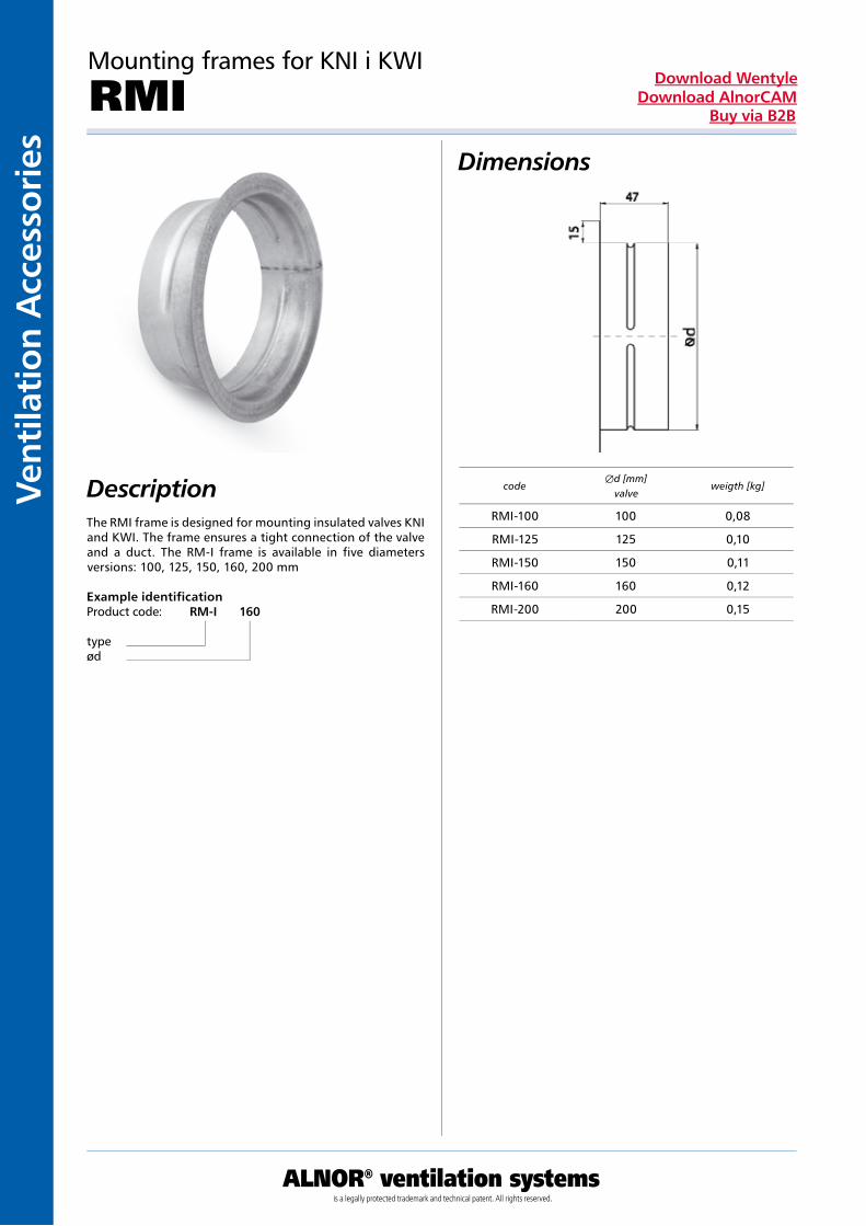
DescriptionThe RMI frame is designed for mounting insulated valves KNI and KWI. The frame ensures a tight connection of the valve and a duct. The RM-I frame is available in five diameters versions: 100, 125, 150, 160, 200 mm
Example identificationProduct code: RM-I 160
typeød
codeÆd [mm]
valveweigth [kg]
RMI-100 100 0,08
RMI-125 125 0,10
RMI-150 150 0,11
RMI-160 160 0,12
RMI-200 200 0,15

Ventilation Accessories
ALNOR® ventilation systemsis a legally protected trademark and technical patent. All rights reserved.
Download WentyleDownload AlnorCAM
Buy via B2B
Mounting frames for KNI i KWI
RMLIDimensions
DescriptionThe RMLI frame is designed for mounting insulated valves KNI and KWI. The frame ensures a tight connection of the valve and a duct. The RM-I frame is available in five diameters versions: 100, 125, 150, 160, 200 mm.
Example identificationProduct code: RMLI 160
typeød
codeÆd valve
[mm]weigth
[kg]
RMLI-100 100 0,08
RMLI-125 125 0,10
RMLI-150 150 0,11
RMLI-160 160 0,12
RMLI-200 200 0,15

Vent
ilati
on A
cces
sori
es
ALNOR® ventilation systemsis a legally protected trademark and technical patent. All rights reserved.
Download WentyleDownload AlnorCAM
Buy via B2B
Descriptions
Description
Mounting frames
RM
Where specified in this catalogue, the control valves are supplied with an end cover that is provided with a bayonet socket. The end cover fits directly into SPR ducts, as well as all types of the flexible ducts.
Example identificationProduct code: RM - aaa
typeÆd
Æd A B weight rated [mm] [mm] [mm] [kg]
80 118 50 0,040
100 125 50 0,050
125 155 50 0,065
150 176 50 0,085
160 186 50 0,100
200 230 50 0,140
250 280 50 0,175
dA
B
Ventilation Accessories
ALNOR® ventilation systemsis a legally protected trademark and technical patent. All rights reserved.
Download WentyleDownload AlnorCAM
Buy via B2B
Dimensions
Description
Mounting frames
RMDL
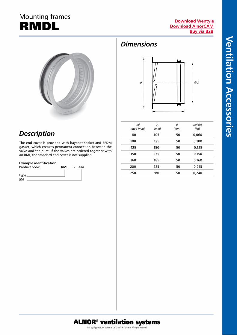
The end cover is provided with bayonet socket and EPDM gasket, which ensures permanent connection between the valve and the duct. If the valves are ordered together with an RMI, the standard end cover is not supplied.
Example identificationProduct code: RML - aaa
typeÆd
Æd A B weight rated [mm] [mm] [mm] [kg]
80 105 50 0,060
100 125 50 0,100
125 150 50 0,125
150 175 50 0,150
160 185 50 0,160
200 225 50 0,215
250 280 50 0,240
B
dA

Vent
ilati
on A
cces
sori
es
ALNOR® ventilation systemsis a legally protected trademark and technical patent. All rights reserved.
Download WentyleDownload AlnorCAM
Buy via B2B
Rosettes
ROZ-HDescription
DescriptionROZ-H chromed rosette. Used as a decorative item to mask the edges of the ventilation duct hole. Material: stainless steel Finish: polished
Example identificationProduct code: ROZ-H 160
typeød
codeÆd
[mm] ÆD
[mm]h
[mm]
ROZ-H-80 90 150 45
ROZ-H-85 95 155 45
ROZ-H-100 110 175 45
ROZ-H-110 120 195 45
ROZ-H-115 125 195 50
ROZ-H-120 130 195 50
ROZ-H-125 135 210 50
ROZ-H-133 143 210 50
ROZ-H-135 145 210 50
ROZ-H-140 150 210 55
ROZ-H-150 160 245 60
ROZ-H-160 170 240 65
ROZ-H-200 180 250 70
ROZ-H-300 190 255 70
D
h
Ventilation Accessories
ALNOR® ventilation systemsis a legally protected trademark and technical patent. All rights reserved.
Download WentyleDownload AlnorCAM
Buy via B2B
Rosettes
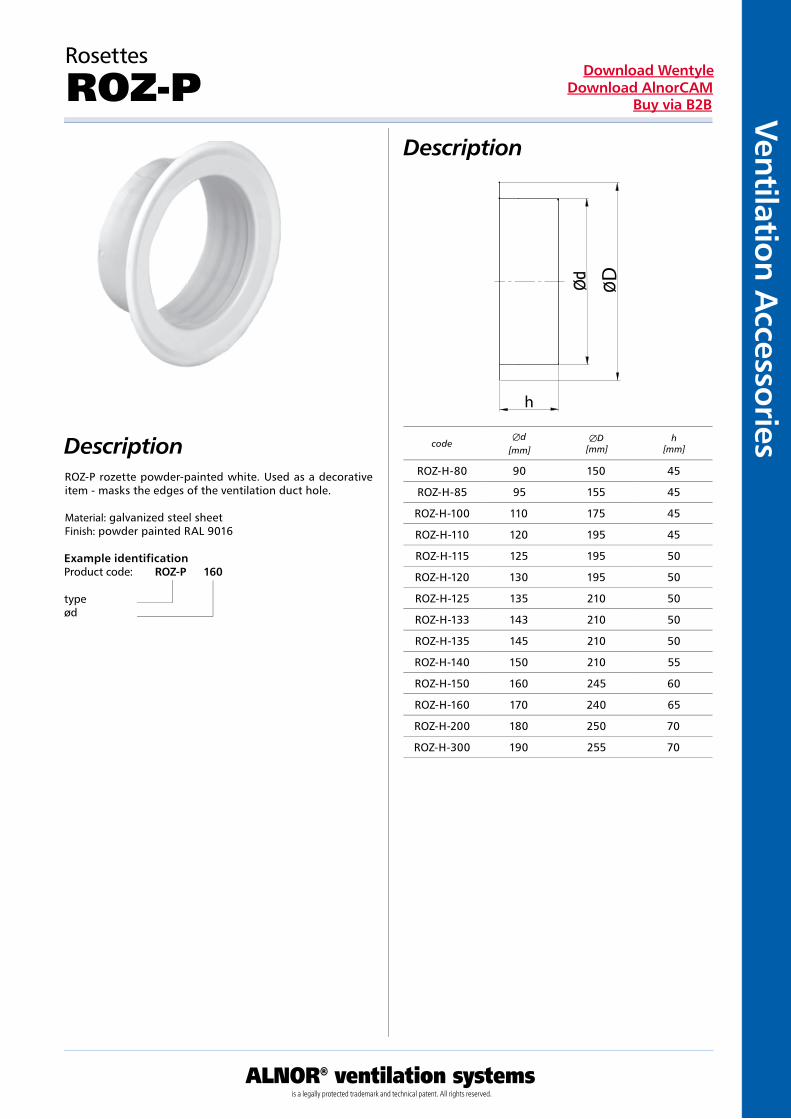
ROZ-PDescription
DescriptionROZ-P rozette powder-painted white. Used as a decorative item - masks the edges of the ventilation duct hole. Material: galvanized steel sheet Finish: powder painted RAL 9016
Example identificationProduct code: ROZ-P 160
typeød
codeÆd
[mm] ÆD
[mm]h
[mm]
ROZ-H-80 90 150 45
ROZ-H-85 95 155 45
ROZ-H-100 110 175 45
ROZ-H-110 120 195 45
ROZ-H-115 125 195 50
ROZ-H-120 130 195 50
ROZ-H-125 135 210 50
ROZ-H-133 143 210 50
ROZ-H-135 145 210 50
ROZ-H-140 150 210 55
ROZ-H-150 160 245 60
ROZ-H-160 170 240 65
ROZ-H-200 180 250 70
ROZ-H-300 190 255 70
D
h

Vent
ilati
on A
cces
sori
es
ALNOR® ventilation systemsis a legally protected trademark and technical patent. All rights reserved.
Download WentyleDownload AlnorCAM
Buy via B2B
Chrome-Nickel Ventilation Cap Supply and Roof Valve
KCN Dimensions
DescriptionKCN valves are designed for supply and roof ventilation systems.They provide smooth control capabilities to adjust precisely the air flow. The design of the control ensures optimal ope-ration in both types of installation. The valves show a very attractive appearance, durability, and are easy to install.
Material: steel sheetFurnishing: polishing
Example identificationProduct code: KCN aaa
typeÆd
d[mm]
A[mm]
B[mm]
C[mm]
100 97 118 52
125 120 141 52
150 145 162 62
160 155 172 62
200 195 208 70

Ventilation Accessories
ALNOR® ventilation systemsis a legally protected trademark and technical patent. All rights reserved.
Download WentyleDownload AlnorCAM
Buy via B2B
Dimensions
Description
Plastic Air Valve
KPP
The KPP air valve is used in intake and exhaust systems.It is made of white PVC what makes it resistant to corrosion. Adju-stment of air flow is made by rotating an internal part of the valve. A selected gap is fixed by means of a locking nut. Con-struction of the valve ensures a low level of noise. The KPP valve is connected to a duct with use of an assembly frame screwed to the valve with use of thread.
Example identificationProduct code: KPP - aaa
typeÆd
type d1
[mm]L
[mm]h
[mm]
KPP-100 100 50 15
KPP-125 125 50 15
KPP-160 160 50 15
KPP-200 200 50 15

Vent
ilati
on A
cces
sori
es
ALNOR® ventilation systemsis a legally protected trademark and technical patent. All rights reserved.
Download WentyleDownload AlnorCAM
Buy via B2B
Wall-Mounted Air Intake/Roof Ejector
UELA Dimensions
DescriptionDepending on their application, UELA components can be used as air intakes or roof ejectors. In addition, the air intake is provided with insect mesh. It is well sealed and fitted with mounting clamps to make its installation easier. The external ring has two mounting holes.UELA components are featured by an attractive appe-arance and long durability. They can be used both indoors and outdoors.
Material: steel sheetFurnishing: polishing
Example identificationProduct code: UELA aaa
typeÆd
d[mm]
A[mm]
B[mm]
C[mm]
100 97 133 52
125 120 165 52
150 145 192 62
160 155 192 62
200 195 253 62

Ventilation Accessories
ALNOR® ventilation systemsis a legally protected trademark and technical patent. All rights reserved.
Download WentyleDownload AlnorCAM
Buy via B2B
Chrome-Nickel Wall-Mounted Air Intake/ExhaustAir Ejector with Overlap
UVLA Dimensions
DescriptionDepending on their application, UELA components can be used as air intakes or roof ejectorsFurnished with a semicircular protection cover preventing the air from being blown in and slanting blades that guide the air flow downwards. In addition, the air intake is provided with insect mesh. It has rubber gaskets and is fitted with mounting clamps to make its installation easier. It is featured by an attractive appearance and long durability and can be used both indoors and outdoors. Material: steel sheetFurnishing: polishing
Example identificationProduct code: UVLA aaa
typeÆd
d[mm]
A[mm]
B[mm]
C[mm]
100 97 133 52
125 120 165 52
150 145 192 62
160 155 192 62
200 195 253 62

Vent
ilati
on A
cces
sori
es
ALNOR® ventilation systemsis a legally protected trademark and technical patent. All rights reserved.
Download WentyleDownload AlnorCAM
Buy via B2B
Chrome-Nickel Wall-Mounted Air Intake/ExhaustAir Ejector with Overlap
USLA Dimensions
Description
Example identificationProduct code: USLA aaa
typeÆd
Depending on their application, USLA components can be used as air intakes or roof ejectorsFurnished with a semicircular protection cover preventing the air from being blown in. In addition, the air intake is provided with mesh. It has rubber gaskets and is fitted with mounting clamps to make its installation easier. It is featured by an attractive appearance and long durability and can be used both indoors and outdoors. Material: steel sheetFurnishing: polishing
d[mm]
A[mm]
B[mm]
C[mm]
100 97 133 52
125 120 165 52
150 145 192 62
160 155 192 62
200 195 253 62

Ventilation Accessories
ALNOR® ventilation systemsis a legally protected trademark and technical patent. All rights reserved.
Download WentyleDownload AlnorCAM
Buy via B2B
Dimensions
Description
Wall-Mounted Air Intakes/Roof Ejectors
USAV
Depending on its application, the USAV can be used as an external grille of an air intake or roof ejector to either take or eject the air. The grille is provided with screw holes.The grilles in sizes 100-315 are also furnished with bird pro-tection covers (mesh size: 2mm). Sizes 400-1250 can be supplied with bird protection covers upon request.
Size 100 – 315: cast aluminiumSize 400 – 1250: galvanised steel
Example identificationProduct code: USAV - aaa
typeÆd
d[mm]
A[mm]
B[mm]
C[mm]
F[m2]
weight[kg]
100 125 5,0 15 0,0044 0,16
125 150 5,0 15 0,0068 0,27
150 175 5,0 15 0,0098 0,32
160 185 5,0 15 0,0120 0,37
200 225 5,0 15 0,0200 0,65
250 275 5,0 15 0,0310 1,12
315 350 7,0 15 0,0470 1,90
400 430 1,0 50 0,0750 3,00
500 530 1,0 50 0,1180 5,50
630 660 1,0 50 0,1870 8,80
B
C
d A

Vent
ilati
on A
cces
sori
es
ALNOR® ventilation systemsis a legally protected trademark and technical patent. All rights reserved.
Download WentyleDownload AlnorCAM
Buy via B2B
Technical Data
Wall-Mounted Air Intakes/Roof Ejectors
USAV
CapacityThe figure shows total pressure Pt (Pa) and noise level LW (dB(A)) as a function of volumetric air flow q (l/s, m3/h).
Noise level in free fieldThe figure shows noise level LW.Noise level within distance x (m).LA = LW − K, see table
Pres
sure
loss
Pt
Pres
sure
loss
Pt
Size
45
40
35
30
25
50
125100 160 200 250
315
200
150
100
70
5040
30
20
15
10
7
5
200
50
30 40 50
1510
70 100 150
20 30 40
300
100
400 500 700
15070
1000
200 300 400
1500
45
40
35
60
55
50
65
200
150
100
70
5040
30
20
15
10
7
5
500400 630 800 1000 1250
3000
1000
5000 7000
1500700
2000
500400
1500
300
1000 10000
2000
7000020000
3000 150005000 7000 10000
5000030000
[l/s]
[m3/h]
[l/s]
[m3/h]
[Pa]
[Pa]
150
Lw(dB(A))
Lw(dB(A))

Ventilation Accessories
ALNOR® ventilation systemsis a legally protected trademark and technical patent. All rights reserved.
Download WentyleDownload AlnorCAM
Buy via B2B
Dimensions
Description
External Non-Return Flap Valve with Overlap
USUA
The USUA external non-return flap valve is made of acid-proof sheet metal and suitable for wall mounting using screws. It serves as an roof ejector, and the overlap protects the outlet against rainfall.
Example identificationProduct code: USUA - aaa
typeÆd
type Æ d1
[mm]A x A[mm]
L[mm]
air flow[cm2]
USUA-100 100 137 × 137 52 71
USUA-125 125 167 × 167 52 113
USUA-150 150 167 × 167 62 165

Vent
ilati
on A
cces
sori
es
ALNOR® ventilation systemsis a legally protected trademark and technical patent. All rights reserved.
Download WentyleDownload AlnorCAM
Buy via B2B
Dimensions
Description
External lamella flap
USMS-P
The USMS-P external flap is made of white PVC and is adjusted for assembling on a wall by means of screws. It plays a role of an ejector. Self-acting closing lamellas protect an inlet against precipitations. The USMS-P flap matches diameters from 100 to 125
Example identificationProduct code: USMS-P
type
162
162
136
136
34
Ø98
Ø10
8
Ø11
8
Ø12
3
18

Ventilation Accessories
ALNOR® ventilation systemsis a legally protected trademark and technical patent. All rights reserved.
Download WentyleDownload AlnorCAM
Buy via B2B
Dimensions
Description
External Non-Return Lamella Flap Valve
USMS
The USMS external non-return flap valve is made of acid-proof sheet metal and suitable for wall mounting using screws. It serves as an roof ejector, with self-closing lamel-lae protecting the outlet against rainfall.
Example identificationProduct code: USMS - aaa
typeÆd
type Æ d1
[mm]A x A[mm]
L[mm]
air flow[cm2]
USMS-100 100 137 × 137 52 70
USMS-125 125 167 × 167 52 112
USMS-150 150 167 × 167 62 164

Vent
ilati
on A
cces
sori
es
ALNOR® ventilation systemsis a legally protected trademark and technical patent. All rights reserved.
Download WentyleDownload AlnorCAM
Buy via B2B
Dimensions
Description
External Grille
USUF
The USUF external grille is made of acid-proof sheet metal and suitable for wall mounting using screws. The high housing and slanting lamellae provide protection against rainfall, and the detachable mesh protects against insects.
Example identificationProduct code: USUF - aaa
typeÆd
type Æ d1
[mm]Æ D1
[mm]L
[mm]air flow
[cm2]
USUF-100 100 133 52 57
USUF-125 125 165 52 93
USUF-150 150 192 62 138
Ventilation Accessories
ALNOR® ventilation systemsis a legally protected trademark and technical patent. All rights reserved.
Download WentyleDownload AlnorCAM
Buy via B2B
Dimensions
Description
Grille
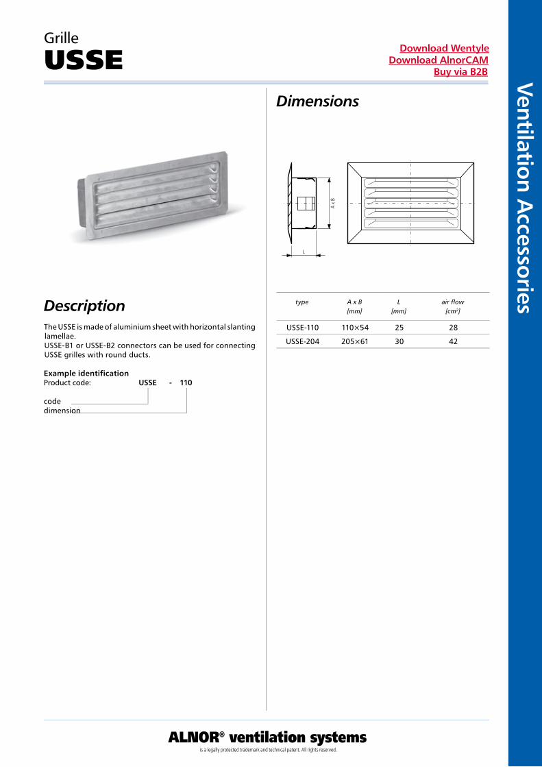
USSE
The USSE is made of aluminium sheet with horizontal slanting lamellae.USSE-B1 or USSE-B2 connectors can be used for connecting USSE grilles with round ducts.
Example identificationProduct code: USSE - 110
codedimension
type A x B[mm]
L[mm]
air flow[cm2]
USSE-110 110×54 25 28
USSE-204 205×61 30 42
L
A x
B

Vent
ilati
on A
cces
sori
es
ALNOR® ventilation systemsis a legally protected trademark and technical patent. All rights reserved.
Download WentyleDownload AlnorCAM
Buy via B2B
Dimensions
Description
Connector
USSE-B1
The USSE-B1 connector is used for fitting USSE grilles to round ducts.
Example identificationProduct code: USSE-B1 - aaa - w
typecodediameter
type A x A[mm]
Æ d1
[mm]
USSE-B1-100-1 110×54 100
USSE-B1-125-1 110×54 125
USSE-B1-150-1 110×54 150
USSE-B1-160-1 110×54 160
USSE-B1-200-1 110×54 200
USSE-B1-250-1 110×54 250
USSE-B1-100-2 205x61 100
USSE-B1-125-2 205x61 125
USSE-B1-150-2 205x61 150
USSE-B1-160-2 205x61 160
USSE-B1-200-2 205x61 200
USSE-B1-250-2 205x61 250
AB

Ventilation Accessories
ALNOR® ventilation systemsis a legally protected trademark and technical patent. All rights reserved.
Download WentyleDownload AlnorCAM
Buy via B2B
Dimensions
Description
Connector
USSE-B2
The USSE-B2 connector is used for fitting USSE grilles to round ducts.
Example identificationProduct code: USSE-B2 - aaa - w
typecodediameter
type A x A[mm]
Æ d1
[mm]e
[mm]
USSE-B2-100-1 110×54 100 36
USSE-B2-125-1 110×54 125 36
USSE-B2-150-1 110×54 150 36
USSE-B2-160-1 110×54 160 36
USSE-B2-200-1 110×54 200 36
USSE-B2-250-1 110×54 250 55
USSE-B2-100-2 205x61 100 36
USSE-B2-125-2 205x61 125 36
USSE-B2-150-2 205x61 150 36
USSE-B2-160-2 205x61 160 36
USSE-B2-200-2 205x61 200 36
USSE-B2-250-2 205x61 250 55
A x B

Vent
ilati
on A
cces
sori
es
ALNOR® ventilation systemsis a legally protected trademark and technical patent. All rights reserved.
Download WentyleDownload AlnorCAM
Buy via B2B
Dimensions
Description
Connector
USSE-B3
The USSE-B3 connector is used for fitting USSE grilles to rectangular ducts.
Example identificationProduct code: USSE-B3 - aaa
codesize
type dimension a x b[mm]
USSE-B3 110 108 x 55
USSE-B3 205 205 x 60

Ventilation Accessories
ALNOR® ventilation systemsis a legally protected trademark and technical patent. All rights reserved.
Download WentyleDownload AlnorCAM
Buy via B2B
Dimensions
Description
Acid-Proof Mesh Connector
USAB
The USAB mesh connector is furnished with an end cover for connection to round ducts. It is made of acid-proof material
Example identificationProduct code: USAB - aaa
typeÆd
type Æ d1
[mm]Æ D
[mm]L
[mm]air flow
[cm2]
USAB-100 100 133 52 65
USAB-125 125 165 52 101
USAB-150 150 192 62 147
USAB-160 160 192 62 157
Vent
ilati
on A
cces
sori
es
ALNOR® ventilation systemsis a legally protected trademark and technical patent. All rights reserved.
Download WentyleDownload AlnorCAM
Buy via B2B
Dimensions
Description
Grille
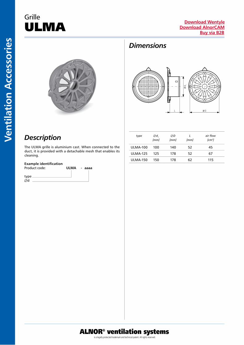
ULMA
The ULMA grille is aluminium cast. When connected to the duct, it is provided with a detachable mesh that enables its cleaning.
Example identificationProduct code: ULMA - aaaa
typeÆd
type Æ d1
[mm]Æ D
[mm]L
[mm]air flow
[cm2]
ULMA-100 100 140 52 45
ULMA-125 125 178 52 67
ULMA-150 150 178 62 115

Ventilation Accessories
ALNOR® ventilation systemsis a legally protected trademark and technical patent. All rights reserved.
Download WentyleDownload AlnorCAM
Buy via B2B
Dimensions
Description
Round duct grills – SGR
SGR
The SGR intake-outtake grill is designed for mounting direc-tly on a round duct by means of delivered screws. Construc-tion of the grill enables its flanges to adhere tightly to a duct plane irrespective of its diameter. The grill is made of galvanized steel, with no welds. It means that it may be used without anticorrosive protections as it has the same surface finishing as ducts. The grill can be equipped with single or double lamellas mounted in vertical and horizontal position. Inclination angle of the lamellas can be adjusted manually. Additionally the grill can be equipped with the SGR-DA angu-lar check damper.
Types of finishing of the grill: galvanized steel sheetThe grill can be powder painted according to RAL 9016
Example identificationProduct code: SGR a bbb ccc
typekindAB
Kind
SGR-0 Single lamellas
SGR-1 Double lamellas
dimension A x B [mm]
min. duct dimension
[mm]
max. duct dimension
[mm]surface [m2]
weight SGR-0 [kg]
weight SGR-1 [kg]
325x75 160 400 0,024 0,9 1,2
425x75 160 400 0,032 1,1 1,4
525x75 160 400 0,039 1,3 1,7
625x75 160 400 0,047 1,5 1,9
825x75 160 400 0,062 1,7 1,9
325x125 250 900 0,040 1,3 1,7
425x125 250 900 0,053 1,5 1,8
525x125 250 900 0,066 1,7 2,0
625x125 250 900 0,078 2,1 2,4
825x125 250 900 0,103 2,5 3,0
425x225 500 1400 0,096 2,7 3,0
525x225 500 1400 0,118 3,1 3,4
625x225 500 1400 0,141 3,4 3,7
825x225 500 1400 0,186 4,8 5,1
A + 40
A BWymiary otworu
B +
50
47
B
A
x
x
Dimension of a hole

Vent
ilati
on A
cces
sori
es
ALNOR® ventilation systemsis a legally protected trademark and technical patent. All rights reserved.
Download WentyleDownload AlnorCAM
Buy via B2B
Technical DataTable
Pt(Pa) - pressure lossLA(dB(A)) - Acoustic pressure level
Round duct grills – SGR
SGR
selection char t
Przepływ(m3/h)
A x B 425 x 75 525 x 75 625 x 75 425 x 125 525 x 125 625 x 125 425 x 225 525 x 225 625 x 225 825 x 225
Pole (m2) 0,0130 0,0160 0,0190 0,0250 0,0310 0,0370 0,0490 0,0610 0,0730 0,0970
200 X (m) 5,1 4,6
24 20
Pt (Pa) 12 8
250 X (m) 6,4 5,7 5,3
29 25 22
Pt (Pa) 19 12 9
300 X (m) 7,6 6,9 6,3 5,5
33 29 26 21
Pt (Pa) 27 18 13 7
350 X (m) 8,9 8 7,4 6,4 5,8
37 33 30 24 20
Pt (Pa) 37 24 17 10 6
400 X (m) 10,2 9,2 8,4 7,3 6,6 6
40 36 33 28 23 20
Pt (Pa) 48 32 23 13 8 6
450 X (m) 11,5 10,3 9,5 8,3 7,4 6,8
43 39 36 31 26 23
Pt (Pa) 61 40 29 17 11 8
500 X (m) 11,5 10,5 9,2 8,2 7,6 6,6
42 38 33 29 25 20
Pt (Pa) 50 35 20 13 9 5
600 X (m) 12,6 11 9,9 9,1 7,9 7,1
43 38 33 30 24 20
Pt (P a) 51 29 19 13 8 5
700 X (m) 12,9 11,5 10,6 9,2 8,2 7,5
41 37 34 28 24 20
Pt (Pa) 40 26 18 10 7 5
800 X (m) 14,7 13,2 12,1 10,5 9,4 8,6
45 40 37 31 27 24
Pt (Pa) 52 34 24 14 9 6
900 X (m) 14,8 13,6 11,8 10,6 9,7 8,4
43 40 34 30 26 21
Pt (Pa) 43 30 17 11
1 000 X (m) 15,1 13,1 11,8 10,8 9,3
42 37 33 29 23
Pt (Pa) 37 21 14 10 5
1 200 X (m) 15,7 14,1 12,9 11,2
41 37 33 28
Pt (Pa) 31 20 14
1 400 X (m) 18,4 16,5 15,1 13,1
45 41 37 32
Pt (Pa) 42 27 19 11
1 600 X (m) 18,8 17,2 14,9
44 40 35
Pt (Pa) 35 24 14
1 800 X (m) 19,4 16,8
43 38
Pt (Pa) 31 18
2 000 X (m) 18,7
40
Pt (Pa) 22
L (dB)A
L (dB)A
L (dB)A
L (dB)A
L (dB)A
L (dB)A
L (dB)A
L (dB)A
L (dB)A
L (dB)A
L (dB)A
L (dB)A
L (dB)A
L (dB)A
L (dB)A
L (dB)A
L (dB)A
Ventilation Accessories
ALNOR® ventilation systemsis a legally protected trademark and technical patent. All rights reserved.
Download WentyleDownload AlnorCAM
Buy via B2B
Dimensions
Description
Dampers for SGR grills
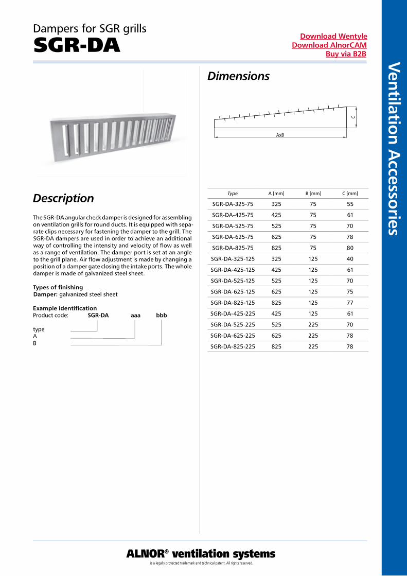
SGR-DA
The SGR-DA angular check damper is designed for assembling on ventilation grills for round ducts. It is equipped with sepa-rate clips necessary for fastening the damper to the grill. The SGR-DA dampers are used in order to achieve an additional way of controlling the intensity and velocity of flow as well as a range of ventilation. The damper port is set at an angle to the grill plane. Air flow adjustment is made by changing a position of a damper gate closing the intake ports. The whole damper is made of galvanized steel sheet.
Types of finishingDamper: galvanized steel sheet
Example identificationProduct code: SGR-DA aaa bbb
typeAB
Type A [mm] B [mm] C [mm]
SGR-DA-325-75 325 75 55
SGR-DA-425-75 425 75 61
SGR-DA-525-75 525 75 70
SGR-DA-625-75 625 75 78
SGR-DA-825-75 825 75 80
SGR-DA-325-125 325 125 40
SGR-DA-425-125 425 125 61
SGR-DA-525-125 525 125 70
SGR-DA-625-125 625 125 75
SGR-DA-825-125 825 125 77
SGR-DA-425-225 425 125 61
SGR-DA-525-225 525 225 70
SGR-DA-625-225 625 225 78
SGR-DA-825-225 825 225 78
AxB
C

Vent
ilati
on A
cces
sori
es
ALNOR® ventilation systemsis a legally protected trademark and technical patent. All rights reserved.
Download WentyleDownload AlnorCAM
Buy via B2B
Dimensions
Description
Rectangular duct grills
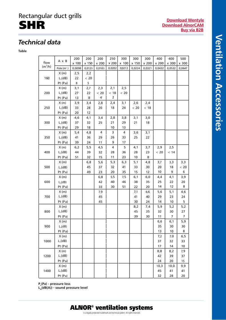
SHR
The SHR intake-outtake grill is designed for mounting on walls of rectangular ducts. The grill is fastened to the duct by means of delivered special clips. The grill is made of galvani-zed steel with no welds. It means that it may be used without anticorrosive protections. Inclination angle of the lamellas can be adjusted manually.
Assembly1 – with use of delivered clipsAccessories 1 – double lamellasType of finishing1 – galvanized steel sheet, powder painted according to RAL 9016
Example identificationProduct code: SHR 1 1 1 bbb ccc
typeassemblyakcesoriafinishingAB
AxB [mm] surface [m2] weight [kg]
200x100 0,010 0,9
200x150 0,012 1,0
200x200 0,018 1,1
250x200 0,021 1,2
300x100 0,022 1,1
300x150 0,023 1,4
300x200 0,032 1,9
400x200 0,043 2,4
400x300 0,053 2,6
500x300 0,064 2,8
A
B +
27
B
A + 27
46
6
A x B(A-27) x (B-27)
Ventilation Accessories
ALNOR® ventilation systemsis a legally protected trademark and technical patent. All rights reserved.
Download WentyleDownload AlnorCAM
Buy via B2B
Technical dataTable
Pt(Pa) - pressure lossLA(dB(A)) - sound pressure level
Rectangular duct grills
SHR
Przepływ
(m3/h)
A x B200
x 100200
x 150500
x 300Pole (m ) 0,0098 0,0125 0,0647
160X (m) 2,5 2,2L (dB) 22 < 20
Pt (Pa) 8 5
200X (m) 3,1 2,7
27 22Pt (Pa) 13
250X (m) 3,9 3,4
33 28Pt (Pa) 20 12
300X (m) 4,6 4,1
37 32Pt (Pa) 29 18
350X (m) 5,4 4,8
41 36Pt (Pa) 39 24
400X (m) 6,2 5,5
44 39Pt (Pa) 51 32
500X (m) 6,8 3,3
45 < 20Pt (Pa) 49
600X (m) 3,9
20Pt (Pa)
700X (m) 4,6
24Pt (Pa)
800X (m) 5,2
27Pt (Pa)
900X (m) 5,9
30Pt (Pa)
1000X (m) 6,5
33Pt (Pa) 10
1200X (m) 7,
37Pt (Pa) 15
1400X (m) 9,9
41Pt (Pa) 20
2
A
L (dB)A
L (dB)A
L (dB)A
L (dB)A
L (dB)A
L (dB)A
L (dB)A
L (dB)A
L (dB)A
L (dB)A
L (dB)A
L (dB)A
L (dB)A
200x 2000,0183
2,3< 20
2,820
3,425
4
29114,532155,637236,842337,94545
8
300x 150
400x 200
0,0224 0,0432
2,6< 20
3,121
3,625
4,1 2,928 < 20105,1 3,733 20156,1 4,438 25227,1 5,641 29308,2 5,945 3239 11
6,635137,
37178,84224
10,34532
300x 100
0212
2,5< 20
3,124
3,82913
3317
36236,341357,54651
4
5
300x 2000,0321
2,4< 18
3,018
3,122
3,7238
4,830126,035206,640247,43530
400x 3000,0532
2,5< 14
3,318
4,122
5,123
5,2307
6,130107,
32148,23920
10,04128
2 0
4
2502000202
2,1< 18
2,418
2,82110
269
28115,332205,54030
3
4
x
0,
2
10 9 6
14 12 8
14 10 5
7
9
8
0,
flow

Vent
ilati
on A
cces
sori
es
ALNOR® ventilation systemsis a legally protected trademark and technical patent. All rights reserved.
Download WentyleDownload AlnorCAM
Buy via B2B
Dimensions
Description
Frame for SHR grate for rectangular ducts
SHR-RM
The SHR-RM assembly frame is designed for mounting the SHR grate in a rectangular duct.
Example identificationProduct code: SHR-RM aaa bbb
typeAB
AxB [mm] surface [m2] weight [kg]
200x100 0,02 0,9
200x150 0,03 1,0
200x200 0,04 1,1
300x100 0,03 1,1
300x150 0,05 1,4
300x200 0,06 1,9
400x200 0,08 2,4
400x300 0,12 2,6
250x200 0,05 1,2
500x300 0,15 2,8

Ventilation Accessories
ALNOR® ventilation systemsis a legally protected trademark and technical patent. All rights reserved.
Download WentyleDownload AlnorCAM
Buy via B2B
Dimensions
Description
Square intake diffusers
NCD-S
The NCD-S square intake diffusers are designed for low- and medium-pressure intake and exhaust ventilation and air-con-dition systems. They can operate with constant and chan-geable air flow, in environments of 70% relative humidity.They are recommended for horizontal intake in accommoda-tions up to 4 m high due to their constant setting of guides. They are mounted on rectangular ventilation ducts, expan-sion boxes and suspended ceilings by means of screws.The diffusers are light and easily assembled, what elimina-tes a necessity of reinforcing of suspended ceilings. Its con-struction enables to take out a central part without disman-tling the whole diffuser.The diffusers are characterized with four-direction intake of air. It is recommended not to use self-locking diffusers in a ceiling position.Using the PRK expansion box, a uniform air flow and dam-ping are obtained when using an insulated box.
Material: aluminiumFinishing: powder paintingStandard colour: RAL 9016
Example identificationProduct code: NCD-S - 295 - 295
typedimension
codeA x A [mm]
B xB [mm]
numberof blades
* typically mounted to the box PRK
NCD-S-295-295 150 295 2
NCD-S-370-370 225 370 3
NCD-S-445-445 305 445 4
NCD-S-520-520 375 520 5
NCD-S-595-595 450 595 6
48

Vent
ilati
on A
cces
sori
es
ALNOR® ventilation systemsis a legally protected trademark and technical patent. All rights reserved.
Download WentyleDownload AlnorCAM
Buy via B2B
Square intake diffusers
NCD-S Dimensions
characteristicdimensions[mm]
A × A[mm]
295-295 150x150 V [m3/h] 170 190 215 235 255 275 300
295-295 150x150 T [m] 1,6-2,5 1,6-2,8 1,9-2,8 2,2-3,1 2,5-3,4 2,5-3,4
295-295 150x150 PS [Pa] 8 9 12 14 17 19 23
295-295 150x150 NC [dB] 15 16 17 19 20 21 22
370-370 225x225 V [m3/h] 380 430 480 525 570 620 670
370-370 225x225 T [m] 2,5-3,7 2,8-4,0 3,1-4,3 3,1-4,3 3,4-4,6 3,4-5,0 3,7-5,0
370-370 225x225 PS [Pa] 9 13 14 17 20 21 27
370-370 225x225 NC [dB] 18 19 21 22 24 25 26
445-445 305x305 V [m3/h] 680 765 850 935 1020 1105 1190
445-445 305x305 T [m] 3,4-5,0 3,7-5,6 4,0-5,9 4,3-6,2 4,3-6,5 4,6-6,8 5,0-7,1
445-445 305x305 PS [Pa] 10 12 16 19 22 23 30
445-445 305x305 NC [dB] 18 20 22 23 25 26 28
520-520 375x375 V [m3/h] 1060 1200 1325 1460 1590 1725 1855
520-520 375x375 T [m] 4,3-6,5 5,0-6,8 5,2-7,1 5,2-7,4 5,6-7,8 5,9-8,1 5,9-8,7
520-520 375x375 PS [Pa] 11 15 18 21 24 28 33
520-520 375x375 NC [dB] 19 21 23 25 27 28 30
595-595 450x450 V [m3/h] 1530 1720 1915 2110 2300 2500 2680
595-595 450x450 T [m] 6,5-7,8 6,2-8,1 6,2-8,7 6,5-9,0 6,5-9,3 6,8-9,9 7,1-10,2
595-595 450x450 PS [Pa] 12 15 18 22 26 29 34
595-595 450x450 NC [dB] 20 21 24 26 28 30 31

Ventilation Accessories
ALNOR® ventilation systemsis a legally protected trademark and technical patent. All rights reserved.
Download WentyleDownload AlnorCAM
Buy via B2B
Dimensions
Description
Expansion boxes to be mounted under the NCD-S diffusers
PRK
The PRK expansion boxes are the attachment units for square diffusers in low- and medium-pressure ventilation systems. They are used to stabilize air flow as well as to achieve its uniform flow to the diffuser. The boxes may be connected to ventilation systems in lateral or upper plane. They may be equipped with a gate fastened to the intake connector pipe. We produce boxes padded with a flexible and high-tempera-ture resistant, 13 mm thick insulation made of natural rubber. It is possible to order the boxes basing on drawings delive-red by the Customer.
Symbols meaning:Assembly:B – lateral connectionG – upper connectionEquipment:D – with a damperInsulation:I – insulatedMaterial: galvanized steelOptionally acid resistant steelFinishing:Unpainted as a standardOptionally powder-painted according to RAL 9016
Example identificationProduct code: PRK 295 B D I Ød
typesizeconnectionequipmentinsulationdiameter
Type B - lateral connection Type G - upper connection
SizeType of difusser
[mm]
AxA [mm]
H [mm]
Max. Ød [mm]
Stand. Ød
[mm]
L [mm]
295 295-295 143x143 200 140 125 165
370 370-370 230x230 250 200 160 165
445 445-445 293x293 350 280 160 165
520 520-520 364x364 350 315 200 165
595 595-595 440x440 400 355 200 165

Vent
ilati
on A
cces
sori
es
ALNOR® ventilation systemsis a legally protected trademark and technical patent. All rights reserved.
Download WentyleDownload AlnorCAM
Buy via B2B
Dimensions
Description
dimensionof difusser
diffuser capacity [m3/h]
pressure loss / noise level [Pa/dB(A)]
Type
* typically mounted to the box PRW
ilość lamelek
NKSD-C 298-8 8
NKSD-C 396-16 16
NKSD-C 498-24 24
NKSD-C 598-24 24
NKSD-C 598-48 48
NKSD-C 623-24 24
NKSD-C 623-48 48
Swirl cassette diffusers
NKSD-C
The NKSD-C swirl diffusers are used in low and medium pressure ventilation systems. The characteristic feature is an air outlet with intensive swirl due to which air in the room is mixed with blown air. They are provided with adjustable plastic air blades (number of blades: 8 – 48 depending on the type) enabling adjustment of uniform air blow direction. Easy mounting, possibility of assembly with a plenum box. They are designed for operation with changeable or conti-nuous air supply. Applicable for industrial room ventilation. They are mounted in ceiling plane. Due to use of the PRW plenum box the uniform air blow can be obtained as well as dampening when an insulated box is used.
Material: galvanized steelFinishing: powder painted RAL 9016
Example identificationProduct code: NKSD-C 598-48
type
72 90 108 144 162 180 252 360 450 540 720 900 1080
298-8 5/<20 9/<20 15/20 25/27 × 35/38 70/-47 - - - - - -
396-16 - - - - 4<20 8/<20 × 36/37 × 80/55 × × ×
498-24 - - - - - - 10/22 20/33 × × 70/50 × 170/70
598-24 - - - - - - - 9/21 14/26 20/33 33/42 55/47 80/55
598-48 - - - - - - - 7/<20 9/20 13/25 25/35 50/46 90/50
625-24 - - - - - - - - 12/24 26/30 38/40 62/42 78/52
625-48 - - - - - - - - 6/20 12/27 22/37 36/48 80/58

Ventilation Accessories
ALNOR® ventilation systemsis a legally protected trademark and technical patent. All rights reserved.
Download WentyleDownload AlnorCAM
Buy via B2B
Dimensions
Description
Swirl cassette diffusers
NKSD-CB
The NKSD-CB cassette swirl diffuser is designed for low and medium pressure intake ventilation systems in rooms which height is up to 4 meters. Air is diffused through 24 radial wings. The advantage of this diffuser is the perfect diffusion of air stream as well a low level of noise generated during air flow. They are mounted to distribution boxes on ventilation dusts and to suspended ceilings. The diffuser is equipped with a central assembly hole. The diffusers are light and easy to install what eliminates a necessity of reinforcing the con-struction of suspended ceiling.The use of the PRW distribution box ensures consistent air supply and attenuation if the box is insulated.
Material: galvanized steelFinishing: powder painted RAL 9016
Example identificationProduct code: NKSD-CB - 600type
type A x A [mm] Ød [mm]
NKSD-CB - 600 600 545
* typically mounted to the box PRW
A
dØ
Vent
ilati
on A
cces
sori
es
ALNOR® ventilation systemsis a legally protected trademark and technical patent. All rights reserved.
Download WentyleDownload AlnorCAM
Buy via B2B
Dimensions
Description
Swirl cassette diffusers
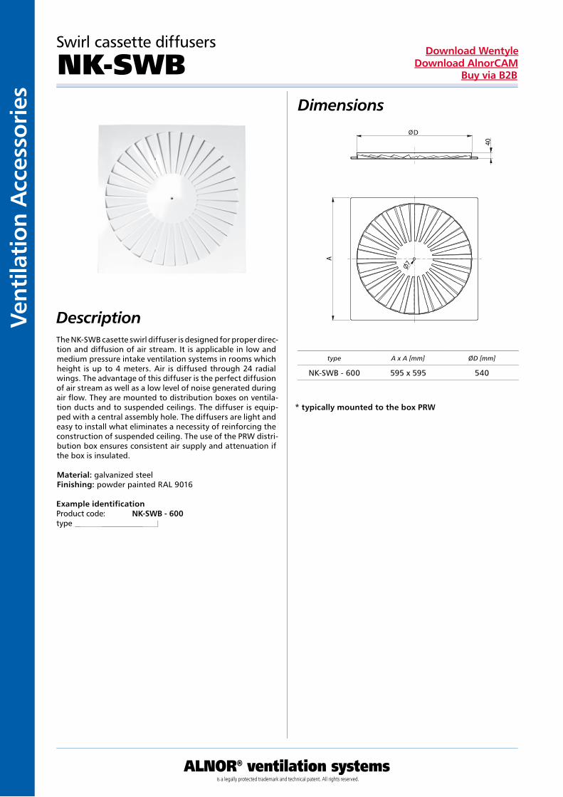
NK-SWB
The NK-SWB casette swirl diffuser is designed for proper direc-tion and diffusion of air stream. It is applicable in low and medium pressure intake ventilation systems in rooms which height is up to 4 meters. Air is diffused through 24 radial wings. The advantage of this diffuser is the perfect diffusion of air stream as well as a low level of noise generated during air flow. They are mounted to distribution boxes on ventila-tion ducts and to suspended ceilings. The diffuser is equip-ped with a central assembly hole. The diffusers are light and easy to install what eliminates a necessity of reinforcing the construction of suspended ceiling. The use of the PRW distri-bution box ensures consistent air supply and attenuation if the box is insulated.
Material: galvanized steelFinishing: powder painted RAL 9016
Example identificationProduct code: NK-SWB - 600type
type A x A [mm] ØD [mm]
NK-SWB - 600 595 x 595 540
* typically mounted to the box PRW
D
A
40
Ventilation Accessories
ALNOR® ventilation systemsis a legally protected trademark and technical patent. All rights reserved.
Download WentyleDownload AlnorCAM
Buy via B2B
Swirl cassette diffusers
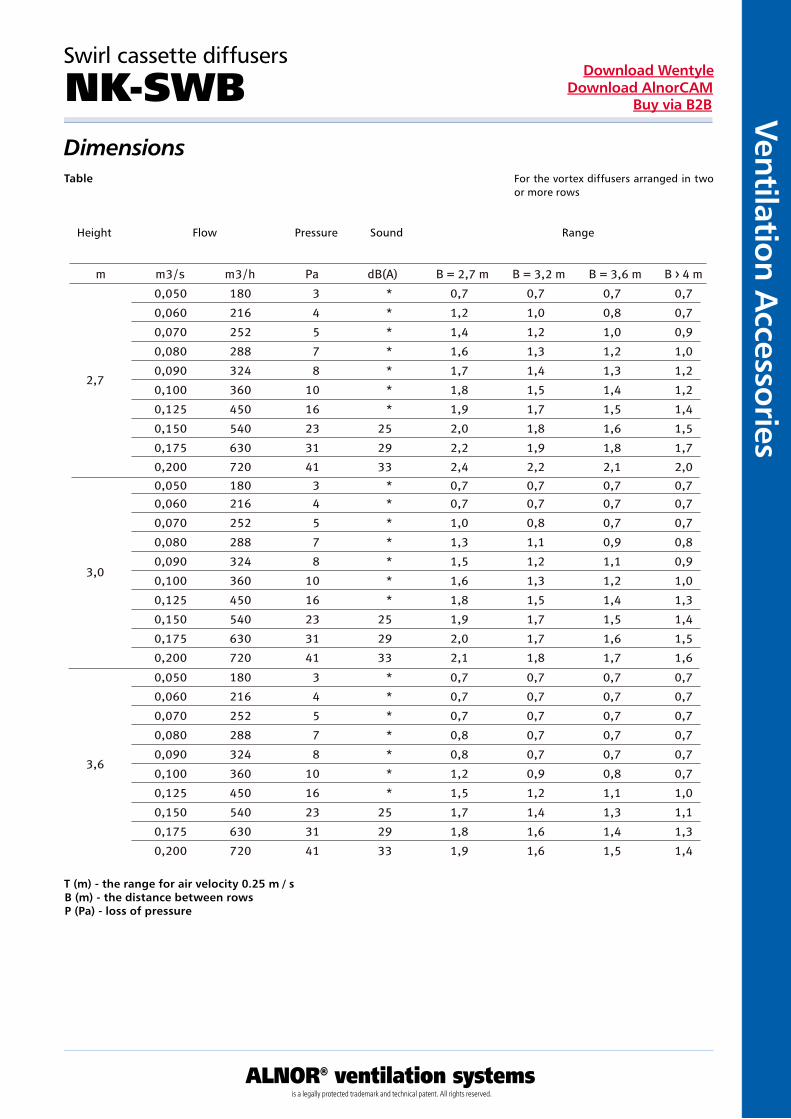
NK-SWB DimensionsTable
T (m) - the range for air velocity 0.25 m / sB (m) - the distance between rowsP (Pa) - loss of pressure
Wysokość Przepływ Zasięg Ciśnienie Hałas
Dla dyfuzorów wirowychrozmieszczonych w dwóch lub więcej rzędach
For the vortex diffusers arranged in two or more rows
Height Flow Pressure Sound Range

Vent
ilati
on A
cces
sori
es
ALNOR® ventilation systemsis a legally protected trademark and technical patent. All rights reserved.
Download WentyleDownload AlnorCAM
Buy via B2B
Dimensions
Description
Expansion boxes to be mounted under the swirl cassette diffuser
PRW
The PRW expansion boxes are the attachment units for swir-ling diffusers in low- and medium-pressure ventilation sys-tems. They are used to stabilize air flow as well as to achieve its uniform flow to the diffuser.The boxes may be connected to ventilation systems in late-ral or upper plane. They can be equipped with a gate faste-ned to the intake connector pipe.The NKSD-C, NK+SWA, NK+SWB, NKSD+CB diffuser is faste-ned to the PRW expansion box by means of a screw rivet.We produce boxes padded with a flexible and high-tempera-ture resistant and insulation made of natural rubber.It is possible to order the boxes basing on drawings delive-red by the Customer.
Symbols meaning:Assembly:B – lateral connectionG – upper connectionEquipment:D – with a damperInsulation:I – insulatedMaterial: galvanized steelOptionally acid resistant steelFinishing:Unpainted as a standardOptionally powder-painted according to RAL 9016
type B - lateral connection type G - upper connection
Rivet nut
Example identificationProduct code: PRW 295 B D I Ød
typesizeconnectionequipmentinsulationdiameter
Type of difusser
[mm]
AxA [mm]
A1xA1
[mm]H
[mm]Max. Ød
[mm]
Stand. Ød
[mm]
L [mm]
298 261x261 291x291 250 200 160 165
396 367x367 391x391 300 250 200 165
498 461x461 491x491 300 250 200 165
598-24 561x561 591x591 330 250 250 165
598-48 580x580 591x591 330 250 250 165
623 595x595 625x625 360 315 315 165
623 595x595 625x625 360 315 315 165

Ventilation Accessories
ALNOR® ventilation systemsis a legally protected trademark and technical patent. All rights reserved.
Download WentyleDownload AlnorCAM
Buy via B2B
Dimensions
Description
Swirl cassette diffusers
NK-SWA
The NK-SWA casette swirl diffuser is designed for proper direc-tion and diffusion of air stream. It is applicable in low and medium pressure intake ventilation systems in rooms which height is up to 4 meters. Air is diffused through 24 radial wings. The advantage of this diffuser is the perfect diffusion of air stream as well as a low level of noise generated during air flow. They are mounted to distribution boxes on ventila-tion ducts and to suspended ceilings. The diffuser is equip-ped with a central assembly hole. The diffusers are light and easy to install what eliminates a necessity of reinforcing the construction of suspended ceiling. The use of the PRW distri-bution box ensures consistent air supply and attenuation if the box is insulated.
Material: galvanized steelFinishing: powder painted RAL 9016
Example identificationProduct code: NK-SWA - 600typ
* typically mounted to the box PRR
type A x A [mm] ØD [mm]
NK-SWA - 300 595 x 595 254
NK-SWA - 400 595 x 595 336
NK-SWA - 500 595 x 595 440
NK-SWA - 600 595 x 595 530
NK-SWA - 625 625 x 625 530
D
A
40

Vent
ilati
on A
cces
sori
es
ALNOR® ventilation systemsis a legally protected trademark and technical patent. All rights reserved.
Download WentyleDownload AlnorCAM
Buy via B2B
Swirl cassette diffusers
NK-SWADimensionsTable
Q (m3 / h) - the volumetric air flowV (m / s) - the air velocityA (m) - distance between diffusersH (m) - distance between ceiling and occupied zone
Wielkość(mm)
Przepływ(m /h)
Strataciśnienia
(Pa)
Poziomtłumienia(dB(A))
Q (m /h)
H (m) V (m/s) A (m)
—
— — —
— — — —
—
— — —
. .
— —
— — — —
— — —
600
600
Wywiew Nawiew
Wielkość(mm)
Przepływ(m /h)
Strataciśnienia
(Pa)
Poziomtłumienia(dB(A))
Size Flow Pressure The level of loss suppression
Size Flow Pressure The level of loss suppression
Exhaust air Supply air

Ventilation Accessories
ALNOR® ventilation systemsis a legally protected trademark and technical patent. All rights reserved.
Download WentyleDownload AlnorCAM
Buy via B2B
Expansion boxes to be mounted under NK-SWA
PRRDimensions
DescriptionPRR-SD-R plenum boxes are connecting elements for NKSD-R round intake diffusers for low and medium pressure venti-lation systems. They are used to stabilize the air flow and obtain an even air supply to the intake diffuser. The plenum box in an instal-lation system may be connected laterally or from the above. They may be fitted with a damper at the exhaust connection. Our boxes are lined with 9mm layer of natural rubber based insulation that is flexible and resistant to high temperatures, It is possible to order pelnum boxes based on your own design drawings. Symbols meaning:Assembly:B – lateral connectionG – upper connectionAssembly:D – with a damperIzolacja:I – insulatedMaterial: galvanized steelOptionally acid resistant steelFinishing:Unpainted as a standardOptionally powder-painted according to RAL 9016
Example identificationProduct code: PRR 300 B D I Æd
typesizeconnectionequipmentisolationdiameter
typ B - ateral connection typ G - upper connection
sizeØD
[mm]Max. Ød
[mm]Dia. Ød[mm]
H[mm]
300 254 224 125 250
400 336 224 125 250
500 440 250 160 300
595 530 315 200 350
625 530 315 200 350
H
ØD
Ød H
ØD
Ød
Vent
ilati
on A
cces
sori
es
ALNOR® ventilation systemsis a legally protected trademark and technical patent. All rights reserved.
Download WentyleDownload AlnorCAM
Buy via B2B
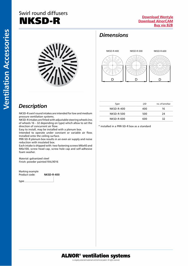
Swirl round diffusers
NKSD-R Dimensions
DescriptionNKSD-R swirl round intakes are intended for low and medium pressure ventilation systems. NKSD-R intakes are fitted with adjustable steering wheels (no. of wheels 16 – 32 depending on type) which allow to set the direction of concurrent air flow. Easy to install, may be installed with a plenum box. Intended to operate under constant or variable air flow. Installed onto the ceiling surface. PRR-SD-R plenum box results in an even air supply and noise reduction with insulated box. Each intake is shipped with: two fastening screws M6x40 and M6x100, screw head cap, screw hole cap and self-adhesive foam washer. Material: galvanized steel Finish: powder painted RAL9016
Marking example Product code: NKSD-R-400
type
* installed in a PRR-SD-R box as a standard
Type ÆD no. of lamellae
NKSD-R-400 400 16
NKSD-R-500 500 24
NKSD-R-600 600 32
D D D
NKSD-R-400 NKSD-R-500 NKSD-R-600

Ventilation Accessories
ALNOR® ventilation systemsis a legally protected trademark and technical patent. All rights reserved.
Download WentyleDownload AlnorCAM
Buy via B2B
Swirl round diffusers
NKSD-R Technical data
Selection graphs
przepustnica przepustnicaNKSD-R-400 NKSD-R-400
przepustnica przepustnicaNKSD-R-500 NKSD-R-500
przepustnic a
6
200 400 500 600 700 800 1200 200 400 500 600 700 800 1200
15213042
70
600/32 przepustnic a
615213042
70
600/32NKSD-R-600 NKSD-R-600
damper damper
damper
damperdamper
damper

Vent
ilati
on A
cces
sori
es
ALNOR® ventilation systemsis a legally protected trademark and technical patent. All rights reserved.
Download WentyleDownload AlnorCAM
Buy via B2B
Expansion boxes to be mounted under NKSD-R
PRR-SD-RDimensions
DescriptionPRR-SD-R plenum boxes are connecting elements for NKSD-R round intake diffusers for low and medium pressure venti-lation systems. They are used to stabilize the air flow and obtain an even air supply to the intake diffuser. The plenum box in an instal-lation system may be connected laterally or from the above. They may be fitted with a damper at the exhaust connection. Our boxes are lined with 9mm layer of natural rubber based insulation that is flexible and resistant to high temperatures, It is possible to order pelnum boxes based on your own design drawings. Marking symbols: Connection: B – lateral connection G – upside connection Equipment: D - with damper Insulation: I - insulated Material: galvanized steel Acid-proof steel on request Finish: Uncoated as a standard On request - powder painted RAL 9016
type B – lateral connection type G – upside connection
Marking example Product code: PRR-SD-R 300 B D I Æd type size connection equipment insulation diameter
dimensionØD
[mm]Max. Ød
[mm]Stand. Ød
[mm]H
[mm]
400 400 200 160 250
500 500 250 160 300
600 600 300 160 350
H
ØD
Ød H
ØD
Ød

Ventilation Accessories
ALNOR® ventilation systemsis a legally protected trademark and technical patent. All rights reserved.
Download WentyleDownload AlnorCAM
Buy via B2B
Dimensions
Description
Round intake diffuser
NCD
The NCD round intake diffusers are designed for low- and medium-pressure intake and exhaust ventilation and air-con-dition systems. They can operate with constant and change-able air flow. Air can be blown as well in vertical as in hori-zontal plane with temperature lower or higher than inside temperature.The diffusers are light and easily assembled. It is possible to assemble them together with a distributor box. Using the PRO distributor box enables to obtain a uniform air flow as well as damping effect when insulated box is used.
Material: aluminiumFinishing: powder-painted according to RAL 9016
Example identificationProduct code: NCD aaa
typesize
* typically mounted to the box PRO or RM-NCD
sizeØA
[mm]Ød
[mm]ØD
[mm]
150 257 149 225
200 307 199 275
250 357 249 325
300 407 299 375
350 457 349 425

Vent
ilati
on A
cces
sori
es
ALNOR® ventilation systemsis a legally protected trademark and technical patent. All rights reserved.
Download WentyleDownload AlnorCAM
Buy via B2B
Round intake diffuser
NCD Technical data
Table
Wydajność(m /h)
Wielkość
Speed v (m/s)
Ps (Pa)
Tmin (m)
Tmax (m)
NC (dB(A))
Speed v (m/s)
Ps (Pa)
Tmin (m)
Tmax (m)
NC (dB(A))
Speed v (m/s)
Speed v (m/s)
Speed v (m/s)
Speed v (m/s)
Speed v (m/s)
Ps (Pa)
Tmin (m)
Tmax (m)
NC (dB(A))
Ps (Pa)
Tmin (m)
Tmax (m)
NC (dB(A))
Ps (Pa)
Tmin (m)
Tmax (m)
NC (dB(A))
Ps (Pa)
Tmin (m)
Tmax (m)
NC (dB(A))
Ps (Pa)
Tmin (m)
Tmax (m)
NC (dB(A))
Ps (Pa)
Tmin (m)
Tmax (m)
NC (dB(A))
Ps (Pa)
Tmin (m)
Tmax (m)
NC (dB(A))
Capacity Size

Ventilation Accessories
ALNOR® ventilation systemsis a legally protected trademark and technical patent. All rights reserved.
Download WentyleDownload AlnorCAM
Buy via B2B
Round intake diffuser
NCD Technical data
Table
Wydajność/h)
Wielkość
Ps (Pa)
Tmin (m)
Tmax (m)
NC (dB(A))
Ps (Pa)
Tmin (m)
Tmax (m)
NC (dB(A))
Ps (Pa)
Tmin (m)
Tmax (m)
NC (dB(A))
Ps (Pa)
Tmin (m)
Tmax (m)
NC (dB(A))
Ps (Pa)
Tmin (m)
Tmax (m)
NC (dB(A))
Ps (Pa)
Tmin (m)
Tmax (m)
NC (dB(A))
Ps (Pa)
Tmin (m)
Tmax (m)
NC (dB(A))
Ps (Pa)
Tmin (m)
Tmax (m)
NC (dB(A))
Ps (Pa)
Tmin (m)
Tmax (m)
NC (dB(A))
(mSpeed v (m/s)
Speed v (m/s)
Speed v (m/s)
Speed v (m/s)
Speed v (m/s)
Speed v (m/s)
Speed v (m/s)
Speed v (m/s)
Capacity Size

Vent
ilati
on A
cces
sori
es
ALNOR® ventilation systemsis a legally protected trademark and technical patent. All rights reserved.
Download WentyleDownload AlnorCAM
Buy via B2B
Dimensions
Description
Example identificationProduct code: PRO 150 B D I Ød
typesizeconnectionequipmentinsulationdiameter
Expansion boxes to be mounted under the NCD
PRO
The PRO expansion boxes are the attachment units for round diffusers in low- and medium-pressure ventilation systems. They are used to stabilize air flow as well as to achieve its uniform flow to the diffuser. The boxes may be connected to ventilation systems in lateral or upper plane. They may be equipped with a gate fastened to the intake connector pipe. We produce boxes padded with a flexible and high-tempera-ture resistant, 13 mm thick insulation made of natural rubber.It is possible to order the boxes basing on drawings delive-red by the Customer.
Symbols meaning:Assembly:B – lateral connectionG – upper connectionEquipment:D – with a damperInsulation:I – insulatedMaterial: galvanized steelOptionally acid resistant steelFinishing:Unpainted as a standardOptionally powder-painted according to RAL 9016
type B - lateral connection type G - upper connection
sizeØD
[mm]Ød
[mm]CxC
[mm]H
[mm]L
[mm]
150 224 wg. zam 280 270 125
200 274 wg. zam 330 310 150
250 312 wg. zam 385 350 175
300 370 wg. zam 430 390 200
350 424 wg. zam 480 440 225

Ventilation Accessories
ALNOR® ventilation systemsis a legally protected trademark and technical patent. All rights reserved.
Download WentyleDownload AlnorCAM
Buy via B2B
Plenum boxes for NCD intake diffusers
PRR-CDDimensions
DescriptionPRR-CD plenum boxes are connecting elements for NCD round intake diffusers for low and medium pressure venti-lation systems. They are used to stabilize the air flow and obtain an even air supply to the intake diffuser. The plenum box in an instal-lation system may be connected laterally or from the above. They may be fitted with a damper at the exhaust connection. Our boxes are lined with 9mm layer of natural rubber based insulation that is flexible and resistant to high temperatures, It is possible to order pelnum boxes based on your own design drawings. Marking symbols: Connection: B – lateral connection G – upside connection Equipment: D - with damper Insulation: I - insulated Material: galvanized steel Acid-proof steel on request Finishing: Uncoated as a standard On request - powder painted RAL 9016
Marking example Product code: PRR-CD 300 B D I Æd type size connection equipment insulation diameter
type B – lateral connection type G – upper connection
sizeØD
[mm]Max. Ød
[mm]Stand. Ød
[mm]H
[mm]
150 220 160 125 200
200 270 200 125 250
250 320 200 160 250
300 370 250 160 300
350 420 250 160 300
H
ØD
Ød H
ØD
Ød
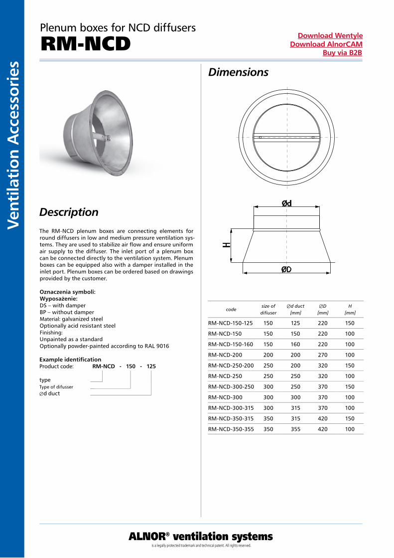
Vent
ilati
on A
cces
sori
es
ALNOR® ventilation systemsis a legally protected trademark and technical patent. All rights reserved.
Download WentyleDownload AlnorCAM
Buy via B2B
Dimensions
Description
Plenum boxes for NCD diffusers
RM-NCD
The RM-NCD plenum boxes are connecting elements for round diffusers in low and medium pressure ventilation sys-tems. They are used to stabilize air flow and ensure uniform air supply to the diffuser. The inlet port of a plenum box can be connected directly to the ventilation system. Plenum boxes can be equipped also with a damper installed in the inlet port. Plenum boxes can be ordered based on drawings provided by the customer.
Oznaczenia symboli:Wyposażenie:DS – with damperBP – without damperMaterial: galvanized steelOptionally acid resistant steelFinishing:Unpainted as a standardOptionally powder-painted according to RAL 9016
Example identificationProduct code: RM-NCD - 150 - 125
typeType of difusserÆd duct
codesize ofdifiuser
Æd duct [mm]
ÆD [mm]
H [mm]
RM-NCD-150-125 150 125 220 150
RM-NCD-150 150 150 220 100
RM-NCD-150-160 150 160 220 100
RM-NCD-200 200 200 270 100
RM-NCD-250-200 250 200 320 150
RM-NCD-250 250 250 320 100
RM-NCD-300-250 300 250 370 150
RM-NCD-300 300 300 370 100
RM-NCD-300-315 300 315 370 100
RM-NCD-350-315 350 315 420 150
RM-NCD-350-355 350 355 420 100

Ventilation Accessories
ALNOR® ventilation systemsis a legally protected trademark and technical patent. All rights reserved.
Download WentyleDownload AlnorCAM
Buy via B2B
Dimension
Description
Long range nozzle
KHA
Example identificationProduct code: KHA - aaa
typeD1
D1
[mm]D2
[mm]D3
[mm]E
[mm]F
[mm]L
[mm]Long range nozzles KHA are applicable in high premises with high volume such as theatre, cinema and industrial halls. High volume flow of air is accompanied by a low level of sound pressure what guarantees a large range of air supply.It is possible to apply the nozzle both for horizontal and ver-tical air supply.The design of the iris-type lifting element allows to change the stream of air in any direction for 30o without causing changes in resistance and sound power.
Material: aluminiumFinish: powder painted acc. to RAL 9016Standard colour: white
100 50 162 10 -2 78
125 64 185 10 4 89
160 82 216 11 10 106
200 108 273 16 14 127
250 136 318 16 23 159
315 174 400 23 29 189
400 230 483 24 47 223
D D
FL
E
D
1 2 3

Vent
ilati
on A
cces
sori
es
ALNOR® ventilation systemsis a legally protected trademark and technical patent. All rights reserved.
Download WentyleDownload AlnorCAM
Buy via B2B
Long range nozzle
KHATechnical Data
LAdB(A) - sound pressure levelq [l/s] - volumetric flowV [m/s] - flow rate
dimension[mm]
stream range
V[m/s]
10 m 20 m 30 m
q[l/s]
LA dB(A)q
[l/s]LA dB(A)
q[l/s]
LA dB(A)
100 - - 26 31 39 42
0,25
125 - - 34 27 50 37
160 23 <20 46 <20 69 32
200 29 <20 61 <20 85 26
250 37 <20 76 <20 106 23
315 50 <20 96 <20 150 21
400 65 <20 129 <20 195 <20
100 26 31 52 50 - -
0,5
125 34 27 68 46 - -
160 46 <20 92 39 138 50
200 61 <20 121 36 182 47
250 76 <20 152 32 229 43
315 98 <20 195 27 293 39
400 129 <20 258 27 387 37
100 52 50 - - - -
1,0
125 68 46 - - -
160 92 39 - - - -
200 121 36 242 49 - -
250 152 32 305 51 -
315 195 27 390 47 585 53
400 258 27 546 45 773 51

Ventilation Accessories
ALNOR® ventilation systemsis a legally protected trademark and technical patent. All rights reserved.
Download WentyleDownload AlnorCAM
Buy via B2B
Round supply diffusers
ACLDimension
DescriptionACL supply diffusers are used with low and medium pressure ventilation systems and air-conditioning intakes and offtakes. They can be used with constant and irregular air-flow. The supplied air may have a temperature lower by 12oC compared to the air temperature in the interior. This allows the AKP inta-kes to be used, for example, in cold storage It is recommend to install on the ceiling surface. Material: aluminium Finish: powder painted Standard color: RAL 9010 on special request, it can be painted in any color from the RAL template.
Example identificationProduct code: ACL aaa
typewielkość
dimensionsØD
[mm]ØL
[mm]ØC
[mm]H
[mm]
125 123 240 200 148
160 158 300 260 158
200 198 360 320 168
250 248 460 420 168
315 313 540 500 168
400 398 540 500 168
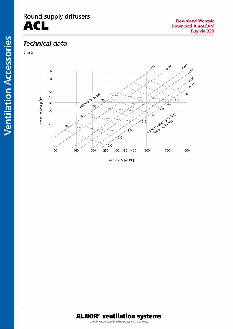
Vent
ilati
on A
cces
sori
es
ALNOR® ventilation systemsis a legally protected trademark and technical patent. All rights reserved.
Download WentyleDownload AlnorCAM
Buy via B2B
Round supply diffusers
ACLTechnical dataCharts
air flow V [m3/h]
volume level d
B
stream co
verage L [m
]
for v=0,25 m
/s
pre
ssur
e lo
ss p
[Pa]

Ventilation Accessories
ALNOR® ventilation systemsis a legally protected trademark and technical patent. All rights reserved.
Download WentyleDownload AlnorCAM
Buy via B2B
Round supply diffusers
ACPDimension
DescriptionACP supply diffusers with perforated surface are intended for low and medium pressure ventilation systems and air-conditioning intakes and offtakes. They can be used with constant and irregular air-flow. The supplied air may have a temperature lower by 12oC compared to the air temperature in the interior. This allows the AKP intakes to be used, for example, in cold storage It is recommend to install on the ceiling surface. Material: aluminium Finish: powder painted Standard color: RAL 9010 on special request, it can be painted in any color from the RAL template.
Example identificationProduct code: ACP aaa
typedimensions
dimensionsØD
[mm]ØL
[mm]ØC
[mm]H
[mm]
125 123 240 200 148
160 158 300 260 158
200 198 360 320 168
250 248 460 420 168
315 313 540 500 168
400 398 540 500 168

Vent
ilati
on A
cces
sori
es
ALNOR® ventilation systemsis a legally protected trademark and technical patent. All rights reserved.
Download WentyleDownload AlnorCAM
Buy via B2B
Round supply diffusers
ACPTechnical dataChartsCharts
air flow V [m3/h]
air flow V [m3/h]
volume level d
B
stream co
verage L [m
]
for v=0,25 m
/s
stream co
verage L [m
]
for v=0,25 m
/s
pre
ssur
e lo
ss p
[Pa]
pre
ssur
e lo
ss p
[Pa]
volume level d
B
volume l
evel
dB
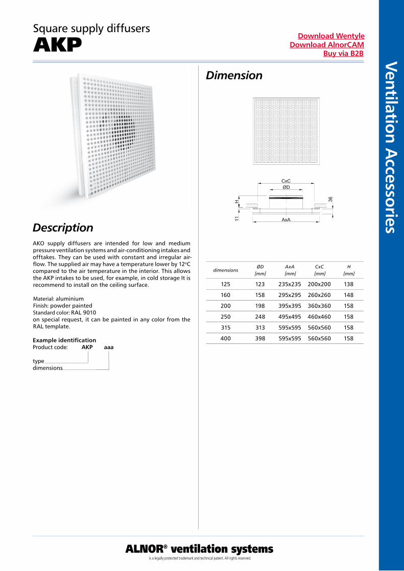
Ventilation Accessories
ALNOR® ventilation systemsis a legally protected trademark and technical patent. All rights reserved.
Download WentyleDownload AlnorCAM
Buy via B2B
Square supply diffusers
AKPDimension
DescriptionAKO supply diffusers are intended for low and medium pressure ventilation systems and air-conditioning intakes and offtakes. They can be used with constant and irregular air-flow. The supplied air may have a temperature lower by 12oC compared to the air temperature in the interior. This allows the AKP intakes to be used, for example, in cold storage It is recommend to install on the ceiling surface. Material: aluminium Finish: powder painted Standard color: RAL 9010 on special request, it can be painted in any color from the RAL template.
Example identificationProduct code: AKP aaa
typedimensions
dimensionsØD
[mm]AxA
[mm]CxC
[mm]H
[mm]
125 123 235x235 200x200 138
160 158 295x295 260x260 148
200 198 395x395 360x360 158
250 248 495x495 460x460 158
315 313 595x595 560x560 158
400 398 595x595 560x560 158

Vent
ilati
on A
cces
sori
es
ALNOR® ventilation systemsis a legally protected trademark and technical patent. All rights reserved.
Download WentyleDownload AlnorCAM
Buy via B2B
Square supply diffusers
AKPTechnical dataCharts
stre
am r
ang
e
pre
ssur
e lo
ss
pre
ssur
e lo
ss
air flow rate
air flow rate
size of the diffuser
size of the diffuser
size of the diffuser
air flow rate
volu
me
leve
l
volu
me
leve
l

Ventilation Accessories
ALNOR® ventilation systemsis a legally protected trademark and technical patent. All rights reserved.
Download WentyleDownload AlnorCAM
Buy via B2B
Round supply diffusers
ITGDimension
DescriptionITG round, long range supply diffusers are intended for high capacity air supply systems. The supplied air may have a temperature lower by 12oC compared to the air temperature in the interior. This allows the ITG intakes to be used, for example, in cold storage The air flow angle may be adjusted, 15o to 30o. By turning the diffuser by 180o it is possible to adjust the air flow focus. Material: galvanized steel sheet Finish: powder painted Standard color: RAL 9010 on special request, it can be painted in any color from the RAL template.
Example identificationProduct code: ITG aaa
typedimensions
dimensionsA
[mm]ØD
[mm]number of hole
[pcs]
200 115 198 2
250 115 248 2
315 115 313 3
400 115 398 3
500 115 498 4
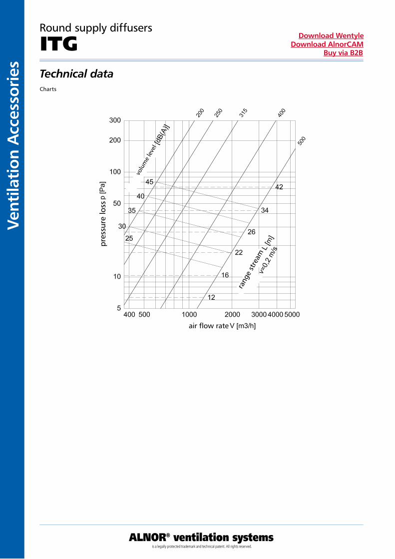
Vent
ilati
on A
cces
sori
es
ALNOR® ventilation systemsis a legally protected trademark and technical patent. All rights reserved.
Download WentyleDownload AlnorCAM
Buy via B2B
Round supply diffusers
ITGTechnical dataCharts
volu
me
leve
l
pres
sure
loss
air flow rate
rang
e st
ream

Ventilation Accessories
ALNOR® ventilation systemsis a legally protected trademark and technical patent. All rights reserved.
Download WentyleDownload AlnorCAM
Buy via B2B
Round supply diffusers
DKFDimension
DescriptionDKF supply diffusers are for low and medium pressure venti-lation systems and air-conditioning intakes and offtakes. They can be used with constant and irregular air-flow. DKF supply diffusers may be used for heating of cooling the interior. DKF supply diffusers allow for a high amount of supplied air. It is recommend to install on the ceiling surface. Material: galvanized steel sheet Finish: powder painted Standard color: RAL 9010 on special request, it can be painted in any color from the RAL template.
Example identificationProduct code: DKF aaa
typedimension
dimensionØD
[mm]ØL
[mm]ØM
[mm]N
[mm]
125 124 305 270 82
160 159 305 270 82
200 199 378 330 84
250 249 477 420 99
315 314 591 530 116
400 398 690 630 128

Vent
ilati
on A
cces
sori
es
ALNOR® ventilation systemsis a legally protected trademark and technical patent. All rights reserved.
Download WentyleDownload AlnorCAM
Buy via B2B
Round supply diffusers
DKFTechnical dataCharts
pre
ssur
e lo
ss p
[Pa]
pre
ssur
e lo
ss p
[Pa]
air flow V [m3/h]
air flow V [m3/h]
strea
m cover
age L
[m]
for v=0,25 m
/s
strea
m cover
age L
[m]
for v=0,25 m
/s
volume level d
B
volume level d
B

Ventilation Accessories
ALNOR® ventilation systemsis a legally protected trademark and technical patent. All rights reserved.
Download WentyleDownload AlnorCAM
Buy via B2B
Dimensions
Description
Steel Wall Air Intake grill
CSQ
Wall air intake grilles are produced with fixed shutters pro-tected with a 12,7 x 12,7 mm mesh made of 1 mm dia. ga-lvanized wire. They are mounted on walls or as a termination of ventilation ducts.They are made of galvanized steel sheet. Optionally they can be powder painted with any RAL colour.The product has the hygienic certificate HK/B/1652/01/2007.
Example identificationProduct code: CSQ - 2500 - 500
type
a
b
a
b
628

Vent
ilati
on A
cces
sori
es
ALNOR® ventilation systemsis a legally protected trademark and technical patent. All rights reserved.
Download WentyleDownload AlnorCAM
Buy via B2B
Dimensions
Description
a
b
588
Aluminium Wall Air Intake Grill
CSQ-A
Wall air intake grilles are produced with fixed shutters pro-tected with a 12,7 x 12,7 mm mesh made of 1 mm dia. ga-lvanized wire. They are mounted on walls or as a termination of ventilation ducts.They are made of aluminium. Optionally they can be powder painted.The product has the hygienic certificate HK/B/1652/01/2007.
Example identificationProduct code: CSQ-A - 2500 - 500
type
a
b

Ventilation Accessories
ALNOR® ventilation systemsis a legally protected trademark and technical patent. All rights reserved.
Download WentyleDownload AlnorCAM
Buy via B2B
Steinlees Steel Wall Air Intake Grill
CSQ-KDimensions
DescriptionWall mounted air intakes are fitted with fixed shutters protec-ted with a 12,7 x 12,7 mm mesh made of 1 mm dia. galvanized wire. Installed on walls or as a termination of ventilation ducts. Made of acid-proof steel sheet. On request, it may be powder painted in any RAL template color. The product has a hygiene certification HK/B/1652/01/2007.
Example identificationProduct code: CSQ-K - 2500 - 500
type
a b
a
b
628
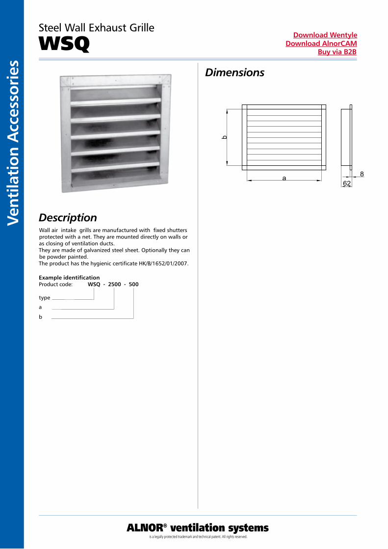
Vent
ilati
on A
cces
sori
es
ALNOR® ventilation systemsis a legally protected trademark and technical patent. All rights reserved.
Download WentyleDownload AlnorCAM
Buy via B2B
Dimensions
DescriptionWall air intake grills are manufactured with fixed shutters protected with a net. They are mounted directly on walls or as closing of ventilation ducts.They are made of galvanized steel sheet. Optionally they can be powder painted.The product has the hygienic certificate HK/B/1652/01/2007.
a
b
628
Steel Wall Exhaust Grille
WSQ
Example identificationProduct code: WSQ - 2500 - 500
type
a
b

Ventilation Accessories
ALNOR® ventilation systemsis a legally protected trademark and technical patent. All rights reserved.
Download WentyleDownload AlnorCAM
Buy via B2B
Dimensions
Description
Aluminium Wall Exhauts Grille
WSQ-A
Wall air intake grills are manufactured with fixed shutters protected with a net. They are mounted directly on walls or as closing of ventilation ducts.They are made of aluminium. Optionally they can be powder painted.The product has the hygienic certificate HK/B/1652/01/2007.
a
b
588
Example identificationProduct code: WSQ-A - 2500 - 500
type
a
b

Vent
ilati
on A
cces
sori
es
ALNOR® ventilation systemsis a legally protected trademark and technical patent. All rights reserved.
Download WentyleDownload AlnorCAM
Buy via B2B
Steinless Steel Wall Exhauts Grille
WSQ-KDimensions
DescriptionWall-mounted air intakes with fixed shutters. Installed on walls or as a termination of ventilation ducts. Made of acid-proof steel sheet. On request, it may be powder painted in any RAL template color. The product has a hygiene certification HK/B/1652/01/2007.
Example identificationProduct code: WSQ-K - 2500 - 500
type
a b
a
b
628


