47
Final Presentation Procter & Gamble: Gillette, South Boston Summer 2014 Internship Hannah Neitzke Automation & Packaging Equipment Engineering Manager: Keith Swenson

Final Presentation Procter & Gamble: Gillette, South Boston
Summer 2014 Internship
Hannah Neitzke Automation & Packaging Equipment Engineering
Manager: Keith Swenson

2
Personal Background Hometown: Sugarland, TX
Education: Louisiana State University:
BSME, May 2015
Interests: Soccer, College Football,
Engineering, Mountain Biking, The
Outdoors, Good Country Music
Sugarland
LSU
“Goal Diggers”

Summer Projects •Set-up Gauges
•ASAM/JSAM
•Blade Break & Transfer Station
•Jump-start for next project
•Automated Carrier Reference Station
•FCAM Chassis
•What is it?
•Measures variation in the location
of dowel pins on Precision Link
Carrier
•Purpose: ensures accurate assembly of
product takes place
•Digital Value Chain
•Will allow for instant update of
information throughout the company
ASAM Gauge
20%
Carrier
Reference
Station
70%
DVC
10%
Project Breakdown

Project #1:
Set-up Gauges Blade Break & Transfer Station
ASAM/JSAM

Blade Break & Transfer Process
Nest Indexes under tooling
Vacuum Head clamps the blade
Nest tooling pivots and snaps blade
Vacuum Head transfers blade and places in housing on
nest
Nest indexes to next station
Nest for Blade Break & Transfer Station Blade Break & Transfer Station
on ASAM/JSAM
Main Objective: Snaps the blade and transfer to housing

Purpose of Set-up Gauge
•Locates vacuum head to correct
location of blade
•Ensures breaking of blade
will take place
•Ensures accurate placement
of blade in housing

Gauge Requirements
Reference surface
Nest
Vacuum
Head .05 mm
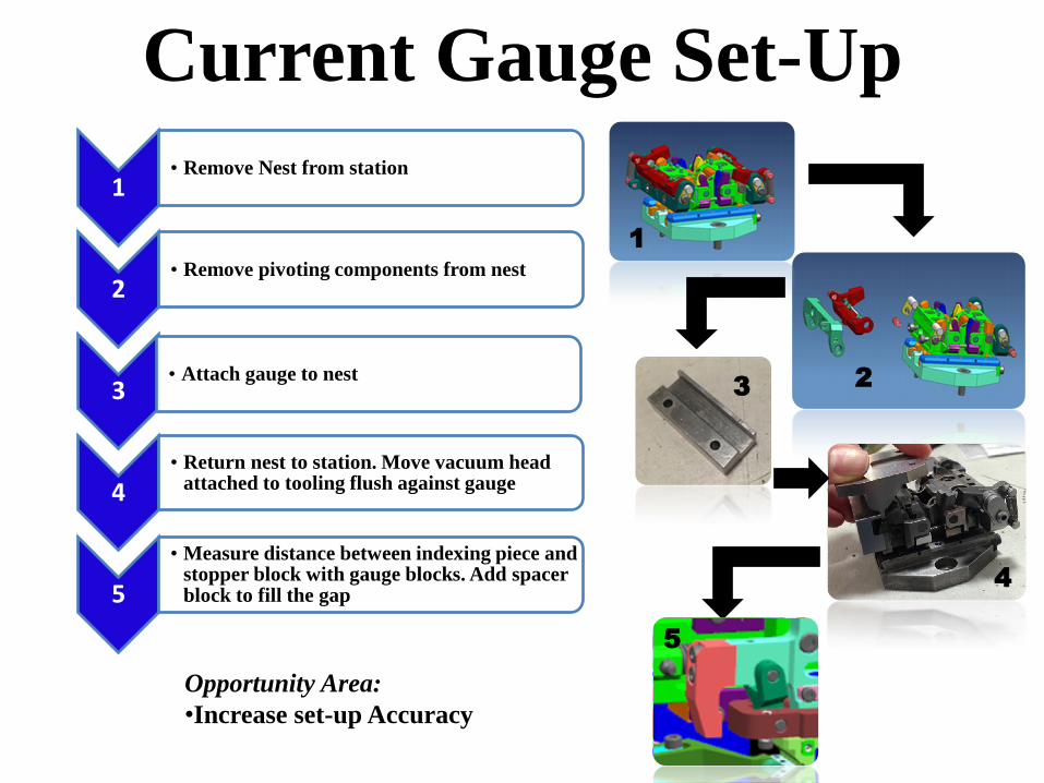
Current Gauge Set-Up
Remove Nest from station
Remove pivoting components from nest
Attach gauge to nest
Return nest to station force suction piece flush against gauge. Ensure stopper block is flush with tooling
1 • Remove Nest from station
2 • Remove pivoting components from nest
3 • Attach gauge to nest
4 • Return nest to station. Move vacuum head
attached to tooling flush against gauge
5
• Measure distance between indexing piece and stopper block with gauge blocks. Add spacer block to fill the gap
1
2 3
4
5
Opportunity Area:
•Increase set-up Accuracy

Gauge Concepts
DESIGN 1 •Attaches to top of nest
•Suction piece fits in slot
•Minus-minus tolerance of
suction piece
DESIGN 2 •“Mock Nest” Design
•Easier Set-up
•Minus-minus tolerance of
suction piece
DESIGN 3 •Replaces suction piece
•H7 fit slot fits over
accurately machined
carbide
•Least tolerance stack-up
Additional Concepts Sketched
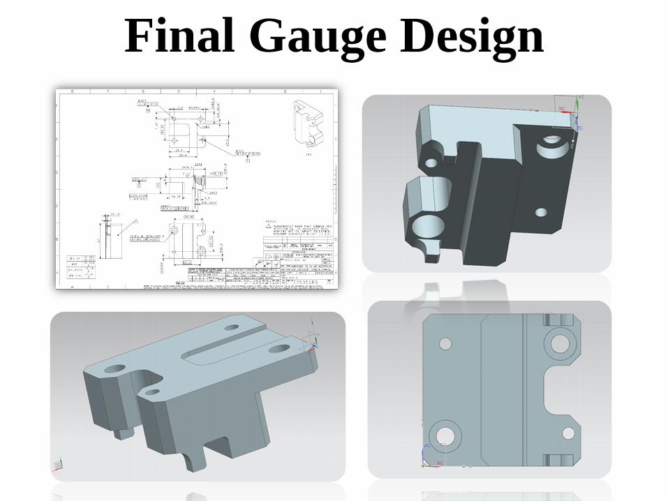
Final Gauge Design
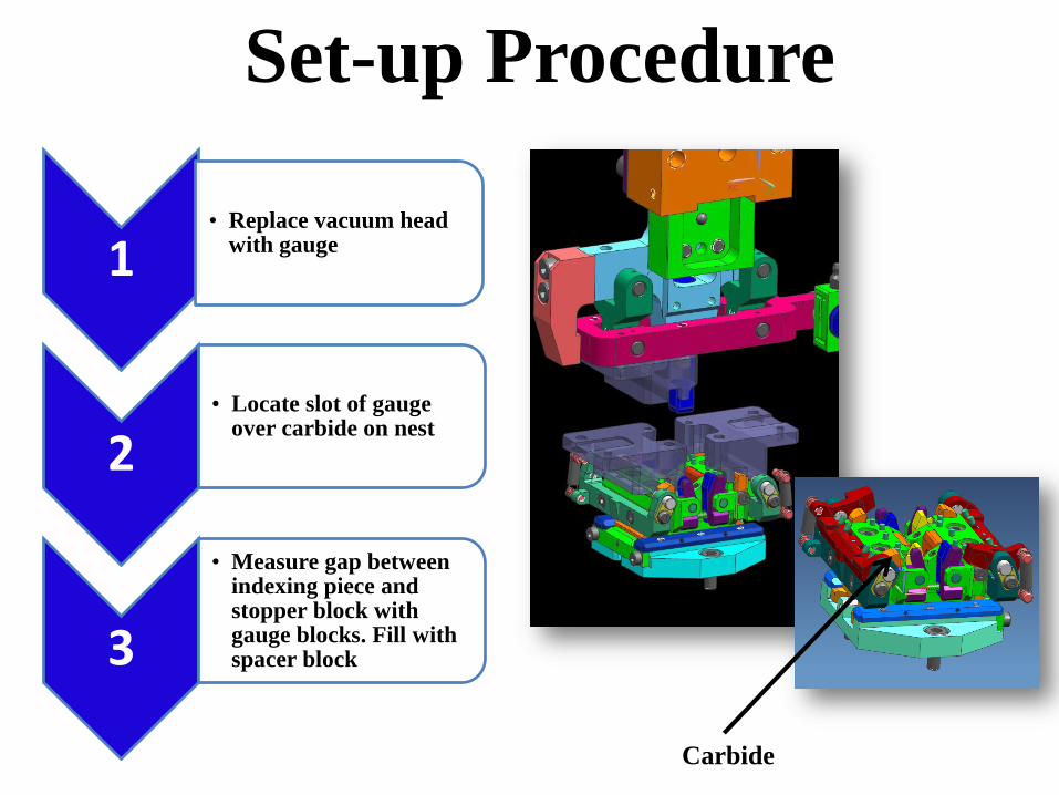
Set-up Procedure
Carbide
1 • Replace vacuum head
with gauge
2 • Locate slot of gauge
over carbide on nest
3
• Measure gap between indexing piece and stopper block with gauge blocks. Fill with spacer block
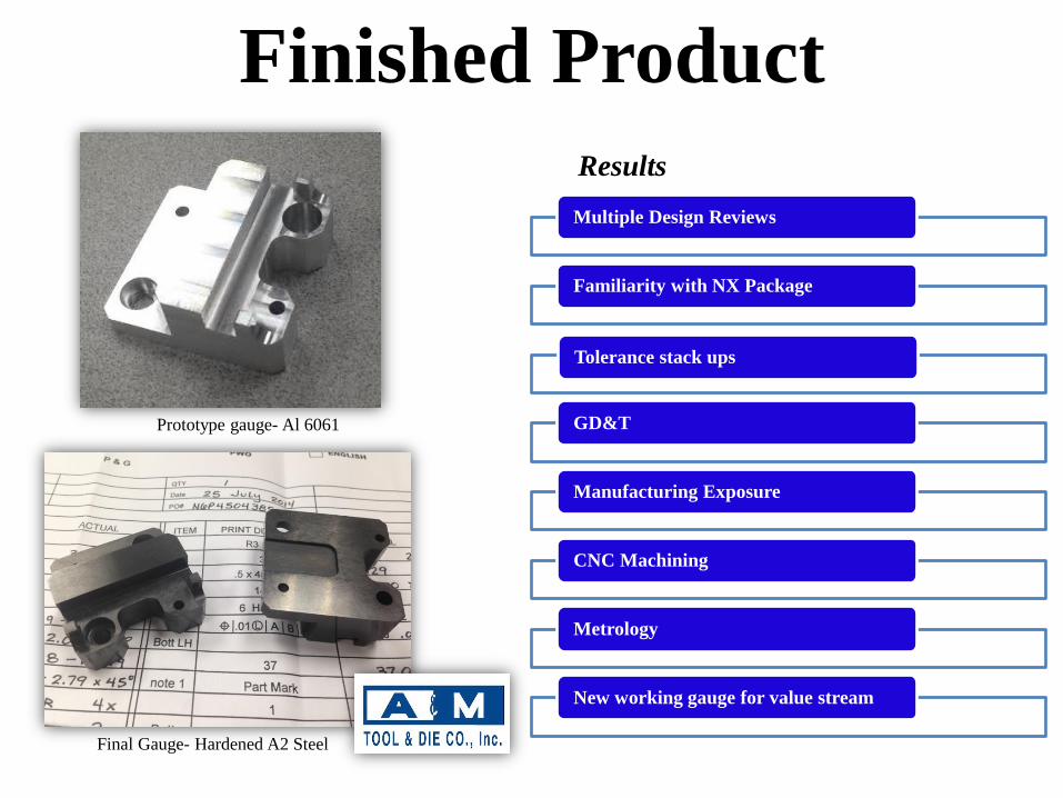
Finished Product
Multiple Design Reviews
Familiarity with NX Package
Tolerance stack ups
GD&T
Manufacturing Exposure
CNC Machining
Metrology
New working gauge for value stream
Results
Prototype gauge- Al 6061
Final Gauge- Hardened A2 Steel

Project #2:
Automated Carrier
Reference Station
Automated Carrier Reference
Station
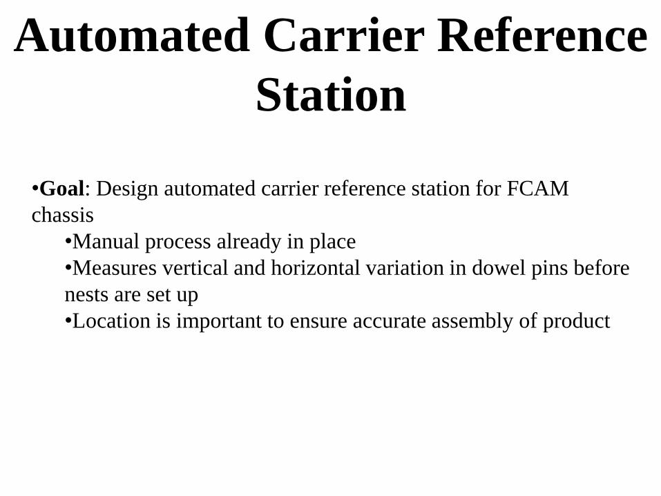
•Goal: Design automated carrier reference station for FCAM
chassis
•Manual process already in place
•Measures vertical and horizontal variation in dowel pins before
nests are set up
•Location is important to ensure accurate assembly of product

Current Process
Current Carrier Reference Station Design
1 • Set up Carrier Reference Station
2 • Apply pre-load to sensor
3 • Manually push indicating tooling forward until
locating pin
4 • Record Measurement
5 • Manually hand wheel chassis to next pin
6 • Repeat process for 101 carriers

Concept Development
Laser
Camera
Mechanically Driven
Servo or Camshaft Driven

Concept Development for Driving
Mechanism Concept 1 Cam
Concept 2 Linear Servo
Concept 3 Curved Rail
driven by
Cam or
Linear Servo
Concept 4 Crank
Mechanism
DESIGN #4

Final Design

Sequence of Operation
1 • Register servo motor with
gage pin and reference block
2 • Chassis indexes, stops at
carrier reference station
3 • Indicator actuates forward
and cams over the pin
4 • Crank and Chassis are both in
dwell
5 • Plunger is actuated back,
reading is transferred to PLC
6 • Indicating piece is actuated
back by crank
7 • Indicator dwells as chassis
moves to next position

Measurements
Horizontal Measurement Vertical Measurement

Custom
Components
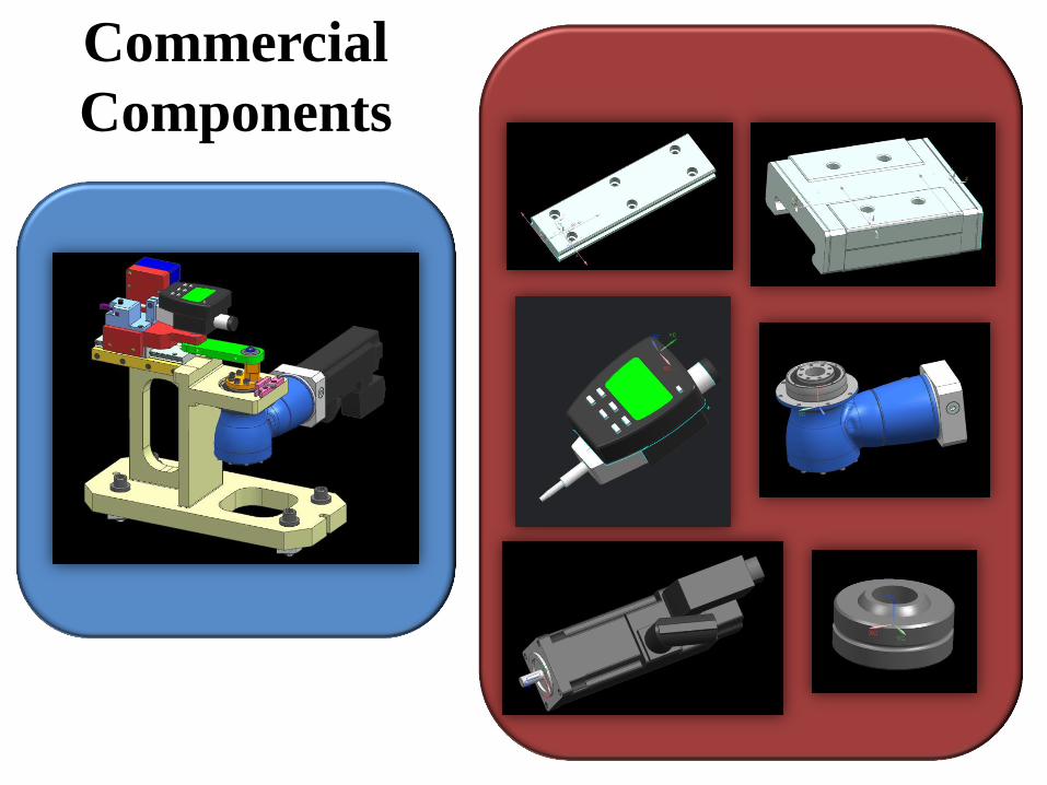
Commercial
Components

Selecting an Indicator
Requirements:
•Data Output
• ≥.001 mm resolution
•Digital
•Plunger Design
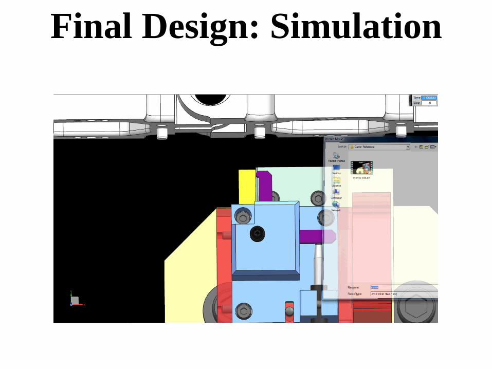
Final Design: Simulation

Timing Diagram
0
0.1
0.2
0.3
0.4
0.5
0.6
0.7
0.8
0.9
1
0 20 40 60 80 100 120 140 160 180 200 220 240 260 280 300 320 340 360
s
θ deg
Position vs. Time Diagram (1 cycle)
Chassis
Tooling
Low Dwell
High Dwell

Kinematics & Dynamics of System
1 • Motion Profile of
Servo
2 • Sizing the Servo

Motion Profile of Servo
1. Select Motion Profile for End
of Arm Tooling
2. Calculate SVAJ curves for
End of Arm Tooling
3. Calculate relationship between
crank angle and machine
angle (servo map)
1

Motion Profile of Servo
STEP 1: Select Motion Profile of End
Piece
•Motion profile for end piece is more logical
solution
1

0
5
10
15
20
25
0 0.5 1 1.5 2 2.5
Po
siti
on
(m
m)
CamShaft Angle, θ
Position vs. Angle
S
β1
0
5
10
15
20
0 0.5 1 1.5 2 2.5
Ve
loci
ty (
mm
/rad
)
CamShaft Angle, θ
Velocity vs. Angle
Velocity vs.Time
β1
-30
-20
-10
0
10
20
30
0 1 2 3
Acc
ele
rati
on
(m
m/r
ad^2
)
CamShaft Angle, θ
Acceleration vs. Angle
Acceleration vs.Angle
β1
Motion Profile of Servo
STEP 2: Calculate SVAJ curves of end piece
1
1

-5
0
5
10
15
20
25
0 50 100 150 200 250 300 350 400
Stro
ke
Machine Angle
Motion of End Piece
Motion Profile of Servo
STEP 2 (continued): Calculate SVAJ curves of end piece
1

Motion Profile of Servo
STEP 3: Solve for position of crank with respect to machine angle
How does θ2 change
with respect to θ?
Need θ2(θ)
1

Motion Profile of Servo
STEP 3 (continued): Solve for position of crank with respect to machine angle
1

Motion Profile of Servo (Analytical
Method)
Implicit Equation
STEP 3 (continued): Solve for position of crank with respect to machine angle
1

Motion Profile of Servo (Analytical
Method)
Solution of Implicit Equation:
STEP 3 (continued): Solve for position of crank with respect to machine angle
1

Motion Profile of Servo (Geometric
Method)
STEP 3 (continued): Solve for position of crank with respect to machine angle
1

Motion Profile of Servo (Geometric
Method)
-50
0
50
100
150
200
250
300
350
400
0 50 100 150 200 250 300 350 400
Cra
nk
An
gle
, θ
2 (
de
gre
es)
Machine Angle, θ (degrees)
Crank Angle vs. Machine Angle (Motion Profile)
STEP 3 (continued): Solve for position of crank with respect to machine angle
1
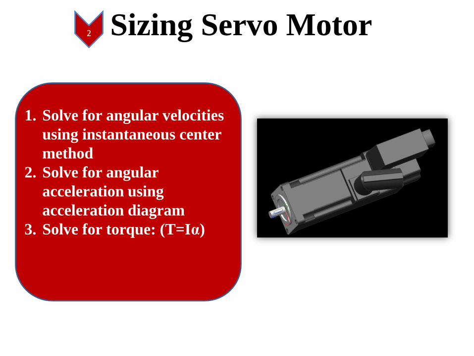
Sizing Servo Motor 2
1. Solve for angular velocities
using instantaneous center
method
2. Solve for angular
acceleration using
acceleration diagram
3. Solve for torque: (T=Iα)
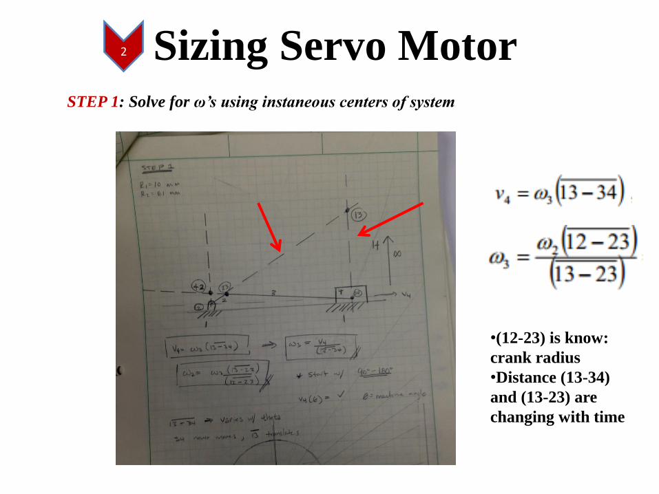
Sizing Servo Motor STEP 1: Solve for ω’s using instaneous centers of system
2
•(12-23) is know:
crank radius
•Distance (13-34)
and (13-23) are
changing with time

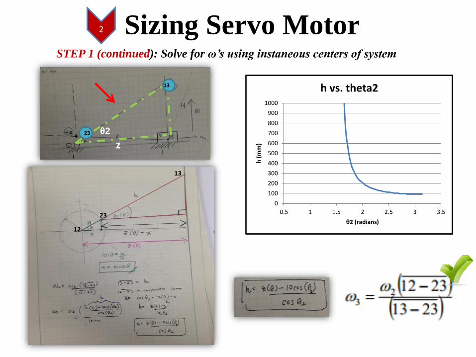
Sizing Servo Motor STEP 1 (continued): Solve for ω’s using instaneous centers of system
0
100
200
300
400
500
600
700
800
900
1000
1.5 1.7 1.9 2.1 2.3 2.5 2.7 2.9 3.1
Y (
mm
)
θ2 (radiians)
Y vs. Crank Angle (rise)
2
13
34`
Y
z θ2
Sizing Servo Motor STEP 1 (continued): Solve for ω’s using instaneous centers of system
0
100
200
300
400
500
600
700
800
900
1000
0.5 1 1.5 2 2.5 3 3.5
h (
mm
)
θ2 (radians)
h vs. theta2
23
13
12
2
13
23 θ2
z

Sizing Servo Motor
0
1
2
3
4
5
6
7
8
9
1 1.2 1.4 1.6 1.8 2 2.2
om
ega
3 (
rad
/se
c)
theta (machine angle)
Omega3 vs. Theta
0
20
40
60
80
100
120
1 1.5 2 2.5
om
ega
2 (
rad
/se
c)
theta(machine angle)
Omega2 vs. Theta
Results for ω2 and ω3 using instaneous centers of system
2
STEP 1 (continued): Solve for ω’s using instaneous centers of system

Sizing Servo Motor STEP 2: Solve for angular acceleration using acceleration diagram.
Repeat for multiple iterations. Draw to scale
2

Sizing Servo Motor
STEP 3: Solve for torque
T=Iα •Inertia calculated from lumped parameter method
•Check following: •Peak Torque ˂ Max Torque
•RMS Torque ˂ Continuous Running Torque
•Driven Inertia ˂ 10*(Driver Inertia)
2

Overall Results of Carrier Reference
Project
Automated system
Quicker Process
Data output
First servo-driven carrier reference station
Wealth of Knowledge

Key Summer Takeaways Collaborative Relationships
Machine Design Experience
Learned from Talented Engineers
Exposure to NX (Modeling, Drawing, Simulations)
Practical application of Kinematics, Dynamics & Machine Design subjects from
school
Welding Lesson
CNC Machining Experience
A&M Machine Shop Tour (Increased Machining Knowledge)
GD&T
Tolerance stack-ups
Opportunities to travel New England
Metrology
New network of friends in Boston

Key Partners
•Keith Swenson
•Chris Zannella
•Loren Gjata
•Dave Morris
•Tim Sweet
•Ken Belliveau
•Arthur Borgeson

THANK YOU!
Questions?


