147
Veritas Storage Foundation™ for Cluster File System Administrator's Guide Linux 5.0 Maintenance Pack 3
Veritas Storage Foundation™for Cluster File SystemAdministrator's Guide
Linux
5.0 Maintenance Pack 3
Veritas Storage Foundation™ for Cluster File SystemAdministrator's Guide
The software described in this book is furnished under a license agreement and may be usedonly in accordance with the terms of the agreement.
Product Version: 5.0 MP3
Documentation version: 5.0MP3.0
Legal NoticeCopyright © 2008 Symantec Corporation. All rights reserved.
Symantec, the Symantec Logo, Veritas, and Storage Foundation, are trademarks or registeredtrademarks of Symantec Corporation or its affiliates in the U.S. and other countries. Othernames may be trademarks of their respective owners.
This Symantec product may contain third party software for which Symantec is requiredto provide attribution to the third party (“Third Party Programs”). Some of the Third PartyPrograms are available under open source or free software licenses. The License Agreementaccompanying the Software does not alter any rights or obligations you may have underthose open source or free software licenses. Please see the Third Party Legal Notice Appendixto this Documentation or TPIP ReadMe File accompanying this Symantec product for moreinformation on the Third Party Programs.
The product described in this document is distributed under licenses restricting its use,copying, distribution, and decompilation/reverse engineering. No part of this documentmay be reproduced in any form by any means without prior written authorization ofSymantec Corporation and its licensors, if any.
THE DOCUMENTATION IS PROVIDED "AS IS" AND ALL EXPRESS OR IMPLIED CONDITIONS,REPRESENTATIONS AND WARRANTIES, INCLUDING ANY IMPLIED WARRANTY OFMERCHANTABILITY, FITNESS FOR A PARTICULAR PURPOSE OR NON-INFRINGEMENT,ARE DISCLAIMED, EXCEPT TO THE EXTENT THAT SUCH DISCLAIMERS ARE HELD TOBE LEGALLY INVALID. SYMANTEC CORPORATION SHALL NOT BE LIABLE FOR INCIDENTALOR CONSEQUENTIAL DAMAGES IN CONNECTION WITH THE FURNISHING,PERFORMANCE, OR USE OF THIS DOCUMENTATION. THE INFORMATION CONTAINEDIN THIS DOCUMENTATION IS SUBJECT TO CHANGE WITHOUT NOTICE.
The Licensed Software and Documentation are deemed to be commercial computer softwareas defined in FAR 12.212 and subject to restricted rights as defined in FAR Section 52.227-19"Commercial Computer Software - Restricted Rights" and DFARS 227.7202, "Rights inCommercial Computer Software or Commercial Computer Software Documentation", asapplicable, and any successor regulations. Any use, modification, reproduction release,performance, display or disclosure of the Licensed Software and Documentation by the U.S.Government shall be solely in accordance with the terms of this Agreement.

Symantec Corporation20330 Stevens Creek Blvd.Cupertino, CA 95014
http://www.symantec.com
Technical SupportSymantec Technical Support maintains support centers globally. TechnicalSupport’s primary role is to respond to specific queries about product featuresand functionality. The Technical Support group also creates content for our onlineKnowledge Base. The Technical Support group works collaboratively with theother functional areas within Symantec to answer your questions in a timelyfashion. For example, the Technical Support group works with Product Engineeringand Symantec Security Response to provide alerting services and virus definitionupdates.
Symantec’s maintenance offerings include the following:
■ A range of support options that give you the flexibility to select the rightamount of service for any size organization
■ Telephone and Web-based support that provides rapid response andup-to-the-minute information
■ Upgrade assurance that delivers automatic software upgrade protection
■ Global support that is available 24 hours a day, 7 days a week
■ Advanced features, including Account Management Services
For information about Symantec’s Maintenance Programs, you can visit our Website at the following URL:
www.symantec.com/techsupp/
Contacting Technical SupportCustomers with a current maintenance agreement may access Technical Supportinformation at the following URL:
www.symantec.com/business/support/index.jsp
Before contacting Technical Support, make sure you have satisfied the systemrequirements that are listed in your product documentation. Also, you should beat the computer on which the problem occurred, in case it is necessary to replicatethe problem.
When you contact Technical Support, please have the following informationavailable:
■ Product release level
■ Hardware information
■ Available memory, disk space, and NIC information
■ Operating system
■ Version and patch level
■ Network topology
■ Router, gateway, and IP address information
■ Problem description:
■ Error messages and log files
■ Troubleshooting that was performed before contacting Symantec
■ Recent software configuration changes and network changes
Licensing and registrationIf your Symantec product requires registration or a license key, access our technicalsupport Web page at the following URL:
www.symantec.com/techsupp/
Customer serviceCustomer service information is available at the following URL:
www.symantec.com/techsupp/
Customer Service is available to assist with the following types of issues:
■ Questions regarding product licensing or serialization
■ Product registration updates, such as address or name changes
■ General product information (features, language availability, local dealers)
■ Latest information about product updates and upgrades
■ Information about upgrade assurance and maintenance contracts
■ Information about the Symantec Buying Programs
■ Advice about Symantec's technical support options
■ Nontechnical presales questions
■ Issues that are related to CD-ROMs or manuals
Maintenance agreement resourcesIf you want to contact Symantec regarding an existing maintenance agreement,please contact the maintenance agreement administration team for your regionas follows:
[email protected] and Japan
[email protected], Middle-East, and Africa
[email protected] America and Latin America
Additional enterprise servicesSymantec offers a comprehensive set of services that allow you to maximize yourinvestment in Symantec products and to develop your knowledge, expertise, andglobal insight, which enable you to manage your business risks proactively.
Enterprise services that are available include the following:
These solutions provide early warning of cyber attacks, comprehensive threatanalysis, and countermeasures to prevent attacks before they occur.
Symantec Early Warning Solutions
These services remove the burden of managing and monitoring security devicesand events, ensuring rapid response to real threats.
Managed Security Services
Symantec Consulting Services provide on-site technical expertise fromSymantec and its trusted partners. Symantec Consulting Services offer a varietyof prepackaged and customizable options that include assessment, design,implementation, monitoring, and management capabilities. Each is focused onestablishing and maintaining the integrity and availability of your IT resources.
Consulting Services
Educational Services provide a full array of technical training, securityeducation, security certification, and awareness communication programs.
Educational Services
To access more information about Enterprise services, please visit our Web siteat the following URL:
www.symantec.com
Select your country or language from the site index.
Technical Support . . . . . . . . . . . . . . . . . . . . . . . . . . . . . . . . . . . . . . . . . . . . . . . . . . . . . . . . . . . . . . . . . . . . . . . . . . . . . . . . . . . . . . . . . . . . . . . 4
Chapter 1 Technical overview . . . . . . . . . . . . . . . . . . . . . . . . . . . . . . . . . . . . . . . . . . . . . . . . . . . . . . . . . . . . . . 13
Storage Foundation Cluster File System architecture ... . . . . . . . . . . . . . . . . . . . . . . . 13About the symmetric architecture ... . . . . . . . . . . . . . . . . . . . . . . . . . . . . . . . . . . . . . . . . . . 13About Storage Foundation Cluster File System primary/secondary
failover ... . . . . . . . . . . . . . . . . . . . . . . . . . . . . . . . . . . . . . . . . . . . . . . . . . . . . . . . . . . . . . . . . . . . . . . . 14About single-host file system semantics using Group Lock
Manager ... . . . . . . . . . . . . . . . . . . . . . . . . . . . . . . . . . . . . . . . . . . . . . . . . . . . . . . . . . . . . . . . . . . . . . . 14About Veritas File System features supported in cluster file
systems .... . . . . . . . . . . . . . . . . . . . . . . . . . . . . . . . . . . . . . . . . . . . . . . . . . . . . . . . . . . . . . . . . . . . . . . . . . . . . 14Veritas File System features in cluster file systems .... . . . . . . . . . . . . . . . . . . 15Veritas File System features not in cluster file systems .... . . . . . . . . . . . . . 16
Storage Foundation Cluster File System benefits andapplications .... . . . . . . . . . . . . . . . . . . . . . . . . . . . . . . . . . . . . . . . . . . . . . . . . . . . . . . . . . . . . . . . . . . . . . . 17How Storage Foundation Cluster File System works .... . . . . . . . . . . . . . . . . . . 17When to use Storage Foundation Cluster File System .... . . . . . . . . . . . . . . . . 18
Chapter 2 Storage Foundation Cluster File Systemarchitecture . . . . . . . . . . . . . . . . . . . . . . . . . . . . . . . . . . . . . . . . . . . . . . . . . . . . . . . . . . . . . . . . . . . . 21
Storage Foundation Cluster File System architecture overview .... . . . . . . . . . 21About Veritas Cluster Server architecture ... . . . . . . . . . . . . . . . . . . . . . . . . . . . . . . . . 21Veritas Volume Manager cluster functionality ... . . . . . . . . . . . . . . . . . . . . . . . . . . 22
When the Storage Foundation Cluster File System primary fails ... . . . . . . . . 23About Storage Foundation Cluster File System and the Group
Lock Manager ... . . . . . . . . . . . . . . . . . . . . . . . . . . . . . . . . . . . . . . . . . . . . . . . . . . . . . . . . . . . . . . . 23About asymmetric mounts ... . . . . . . . . . . . . . . . . . . . . . . . . . . . . . . . . . . . . . . . . . . . . . . . . . . . . 23Parallel I/O .... . . . . . . . . . . . . . . . . . . . . . . . . . . . . . . . . . . . . . . . . . . . . . . . . . . . . . . . . . . . . . . . . . . . . . . . 24Storage Foundation Cluster File System namespace .... . . . . . . . . . . . . . . . . . . 25Storage Foundation Cluster File System backup strategies ... . . . . . . . . . . 25Synchronize time on Cluster File Systems .... . . . . . . . . . . . . . . . . . . . . . . . . . . . . . . . 26Distribute a load on a cluster ... . . . . . . . . . . . . . . . . . . . . . . . . . . . . . . . . . . . . . . . . . . . . . . . . 27File system tuneables ... . . . . . . . . . . . . . . . . . . . . . . . . . . . . . . . . . . . . . . . . . . . . . . . . . . . . . . . . . . . 27Split-brain and jeopardy handling .... . . . . . . . . . . . . . . . . . . . . . . . . . . . . . . . . . . . . . . . . . 27Fencing .... . . . . . . . . . . . . . . . . . . . . . . . . . . . . . . . . . . . . . . . . . . . . . . . . . . . . . . . . . . . . . . . . . . . . . . . . . . . . 28
Contents
Single network link and reliability ... . . . . . . . . . . . . . . . . . . . . . . . . . . . . . . . . . . . . . . . . . . 28I/O error handling policy ... . . . . . . . . . . . . . . . . . . . . . . . . . . . . . . . . . . . . . . . . . . . . . . . . . . . . . . 29
About Veritas Volume Manager cluster functionality ... . . . . . . . . . . . . . . . . . . . . . . . 30Shared disk groups overview .... . . . . . . . . . . . . . . . . . . . . . . . . . . . . . . . . . . . . . . . . . . . . . . . . 31
Chapter 3 Storage Foundation Cluster File Systemadministration . . . . . . . . . . . . . . . . . . . . . . . . . . . . . . . . . . . . . . . . . . . . . . . . . . . . . . . . . . . . . . . 37
About Storage Foundation Cluster File System administration .... . . . . . . . . . 37Veritas Cluster Server overview .... . . . . . . . . . . . . . . . . . . . . . . . . . . . . . . . . . . . . . . . . . . . . . . . . . . 38
About Group Membership and Atomic Broadcast ... . . . . . . . . . . . . . . . . . . . . . . 39About Low Latency Transport ... . . . . . . . . . . . . . . . . . . . . . . . . . . . . . . . . . . . . . . . . . . . . . . . 39
Veritas Volume Manger cluster functionality overview .... . . . . . . . . . . . . . . . . . . . 39Storage Foundation Cluster File System overview .... . . . . . . . . . . . . . . . . . . . . . . . . . . 40
Number of parallel fsck threads to run during recovery istunable ... . . . . . . . . . . . . . . . . . . . . . . . . . . . . . . . . . . . . . . . . . . . . . . . . . . . . . . . . . . . . . . . . . . . . . . . 40
Cluster and shared mounts ... . . . . . . . . . . . . . . . . . . . . . . . . . . . . . . . . . . . . . . . . . . . . . . . . . . . 40Determining or giving primaryship .... . . . . . . . . . . . . . . . . . . . . . . . . . . . . . . . . . . . . . . . 40Asymmetric mounts ... . . . . . . . . . . . . . . . . . . . . . . . . . . . . . . . . . . . . . . . . . . . . . . . . . . . . . . . . . . . . 41Storage Foundation Cluster File System and Veritas Volume
Manager cluster functionality agents ... . . . . . . . . . . . . . . . . . . . . . . . . . . . . . . . . 42Storage Foundation Cluster File System administration
commands .... . . . . . . . . . . . . . . . . . . . . . . . . . . . . . . . . . . . . . . . . . . . . . . . . . . . . . . . . . . . . . . . . . . . . . . . . 42Storage Foundation Cluster File System commands .... . . . . . . . . . . . . . . . . . . 42mount and fsclusteradm commands .... . . . . . . . . . . . . . . . . . . . . . . . . . . . . . . . . . . . . . . 43Time synchronization for Cluster File Systems .... . . . . . . . . . . . . . . . . . . . . . . . . 44Growing a Storage Foundation Cluster File System .... . . . . . . . . . . . . . . . . . . . 44The fstab file ... . . . . . . . . . . . . . . . . . . . . . . . . . . . . . . . . . . . . . . . . . . . . . . . . . . . . . . . . . . . . . . . . . . . . . . 44Distribute the load on a Cluster ... . . . . . . . . . . . . . . . . . . . . . . . . . . . . . . . . . . . . . . . . . . . . . . 45GUIs ... . . . . . . . . . . . . . . . . . . . . . . . . . . . . . . . . . . . . . . . . . . . . . . . . . . . . . . . . . . . . . . . . . . . . . . . . . . . . . . . . . 45
Snapshots on Storage Foundation Cluster File System .... . . . . . . . . . . . . . . . . . . . . 45Cluster snapshot characteristics ... . . . . . . . . . . . . . . . . . . . . . . . . . . . . . . . . . . . . . . . . . . . . 45Performance considerations .... . . . . . . . . . . . . . . . . . . . . . . . . . . . . . . . . . . . . . . . . . . . . . . . . . 46Creating a snapshot on a Storage Foundation Cluster File
System .... . . . . . . . . . . . . . . . . . . . . . . . . . . . . . . . . . . . . . . . . . . . . . . . . . . . . . . . . . . . . . . . . . . . . . . . 46Adding a node to a cluster ... . . . . . . . . . . . . . . . . . . . . . . . . . . . . . . . . . . . . . . . . . . . . . . . . . . . . . . . . . . . 47Configuring Storage Foundation Cluster File System and Cluster
Volume Manager agents on the new node .... . . . . . . . . . . . . . . . . . . . . . . . . . . . . . . . 50Removing a node from a cluster ... . . . . . . . . . . . . . . . . . . . . . . . . . . . . . . . . . . . . . . . . . . . . . . . . . . . 53
Contents8
Chapter 4 Storage Foundation Cluster File System for OracleRAC . . . . . . . . . . . . . . . . . . . . . . . . . . . . . . . . . . . . . . . . . . . . . . . . . . . . . . . . . . . . . . . . . . . . . . . . . . . . . . . . . . . 57
Storage Foundation Cluster File System for Oracle RAC .... . . . . . . . . . . . . . . . . . . 57About Storage Foundation Cluster File System for Oracle
RAC .... . . . . . . . . . . . . . . . . . . . . . . . . . . . . . . . . . . . . . . . . . . . . . . . . . . . . . . . . . . . . . . . . . . . . . . . . . . . 57How SFCFS for Oracle RAC works (high-level perspective) ... . . . . . . . . . . 58Component products and processes of SFCFS for Oracle
RAC .... . . . . . . . . . . . . . . . . . . . . . . . . . . . . . . . . . . . . . . . . . . . . . . . . . . . . . . . . . . . . . . . . . . . . . . . . . . . 60Communication infrastructure ... . . . . . . . . . . . . . . . . . . . . . . . . . . . . . . . . . . . . . . . . . . . . . . 60Data flow .... . . . . . . . . . . . . . . . . . . . . . . . . . . . . . . . . . . . . . . . . . . . . . . . . . . . . . . . . . . . . . . . . . . . . . . . . . . 60Communication requirements ... . . . . . . . . . . . . . . . . . . . . . . . . . . . . . . . . . . . . . . . . . . . . . . . 61Cluster Volume Manager ... . . . . . . . . . . . . . . . . . . . . . . . . . . . . . . . . . . . . . . . . . . . . . . . . . . . . . . 62Cluster Volume Manager architecture ... . . . . . . . . . . . . . . . . . . . . . . . . . . . . . . . . . . . . . 62Storage Foundation Cluster File System .... . . . . . . . . . . . . . . . . . . . . . . . . . . . . . . . . . 63Storage Foundation Cluster File System architecture ... . . . . . . . . . . . . . . . . . 63Oracle Disk Manager ... . . . . . . . . . . . . . . . . . . . . . . . . . . . . . . . . . . . . . . . . . . . . . . . . . . . . . . . . . . . . 64Oracle Disk Manager architecture ... . . . . . . . . . . . . . . . . . . . . . . . . . . . . . . . . . . . . . . . . . . 64Oracle Disk Manager performance enhancements ... . . . . . . . . . . . . . . . . . . . . . 64Veritas Cluster Server functionality for SFCFS for Oracle
RAC .... . . . . . . . . . . . . . . . . . . . . . . . . . . . . . . . . . . . . . . . . . . . . . . . . . . . . . . . . . . . . . . . . . . . . . . . . . . . 65Veritas Cluster Server architecture ... . . . . . . . . . . . . . . . . . . . . . . . . . . . . . . . . . . . . . . . . 65Cluster configuration files ... . . . . . . . . . . . . . . . . . . . . . . . . . . . . . . . . . . . . . . . . . . . . . . . . . . . . 65Installing and configuring SFCFS for Oracle RAC .... . . . . . . . . . . . . . . . . . . . . . 66Verifying the Oracle Cluster Registry and Vote-disk shared
volumes .... . . . . . . . . . . . . . . . . . . . . . . . . . . . . . . . . . . . . . . . . . . . . . . . . . . . . . . . . . . . . . . . . . . . . . 72Installing Oracle Clusterware and Database software .... . . . . . . . . . . . . . . . . 72Relinking Oracle Database with Veritas Extension for Oracle
Disk Manager ... . . . . . . . . . . . . . . . . . . . . . . . . . . . . . . . . . . . . . . . . . . . . . . . . . . . . . . . . . . . . . . . 72Upgrading Oracle Database .... . . . . . . . . . . . . . . . . . . . . . . . . . . . . . . . . . . . . . . . . . . . . . . . . . . 73
Chapter 5 Fencing administration . . . . . . . . . . . . . . . . . . . . . . . . . . . . . . . . . . . . . . . . . . . . . . . . . . . . . . 81
I/O fencing .... . . . . . . . . . . . . . . . . . . . . . . . . . . . . . . . . . . . . . . . . . . . . . . . . . . . . . . . . . . . . . . . . . . . . . . . . . . . . . . 81Data disks ... . . . . . . . . . . . . . . . . . . . . . . . . . . . . . . . . . . . . . . . . . . . . . . . . . . . . . . . . . . . . . . . . . . . . . . . . . . 81Coordinator Disks ... . . . . . . . . . . . . . . . . . . . . . . . . . . . . . . . . . . . . . . . . . . . . . . . . . . . . . . . . . . . . . . . 82Before you configure coordinator disks ... . . . . . . . . . . . . . . . . . . . . . . . . . . . . . . . . . . . 82Adding or removing coordinator disks ... . . . . . . . . . . . . . . . . . . . . . . . . . . . . . . . . . . . . 85Verifying fenced configurations .... . . . . . . . . . . . . . . . . . . . . . . . . . . . . . . . . . . . . . . . . . . . . 86Disabling I/O fencing .... . . . . . . . . . . . . . . . . . . . . . . . . . . . . . . . . . . . . . . . . . . . . . . . . . . . . . . . . . . 87How I/O fencing works during different events ... . . . . . . . . . . . . . . . . . . . . . . . . . 88
Troubleshooting fenced configurations .... . . . . . . . . . . . . . . . . . . . . . . . . . . . . . . . . . . . . . . . . 90Example of a preexisting network partition (split-brain) ... . . . . . . . . . . . . . 90
9Contents
Recovering from a preexisting network partition(split-brain) ... . . . . . . . . . . . . . . . . . . . . . . . . . . . . . . . . . . . . . . . . . . . . . . . . . . . . . . . . . . . . . . . . . . 91
Chapter 6 Using Veritas Extension for Oracle DiskManager . . . . . . . . . . . . . . . . . . . . . . . . . . . . . . . . . . . . . . . . . . . . . . . . . . . . . . . . . . . . . . . . . . . . . . . . . . 93
About Oracle Disk Manager ... . . . . . . . . . . . . . . . . . . . . . . . . . . . . . . . . . . . . . . . . . . . . . . . . . . . . . . . . . 93How Oracle Disk Manager improves database performance .... . . . . . . . . 95
About Oracle Disk Manager and Storage Foundation Cluster FilesSystem .... . . . . . . . . . . . . . . . . . . . . . . . . . . . . . . . . . . . . . . . . . . . . . . . . . . . . . . . . . . . . . . . . . . . . . . . . . . . . . 96
About Oracle Disk Manager and Oracle Managed Files ... . . . . . . . . . . . . . . . . . . . . . 97How Oracle Disk Manager works with Oracle Managed Files ... . . . . . . . 97
Setting up Veritas Extension for Oracle Disk Manager ... . . . . . . . . . . . . . . . . . . . . . 99Configuring Veritas Extension for Oracle Disk Manager ... . . . . . . . . . . . . . . . . . 100How to prepare existing database storage for Oracle Disk Manager
... . . . . . . . . . . . . . . . . . . . . . . . . . . . . . . . . . . . . . . . . . . . . . . . . . . . . . . . . . . . . . . . . . . . . . . . . . . . . . . . . . . . . . . 102Verifying that Oracle Disk Manager is configured .... . . . . . . . . . . . . . . . . . . . . . . . . 102Disabling the Oracle Disk Manager feature ... . . . . . . . . . . . . . . . . . . . . . . . . . . . . . . . . . . . 103
Chapter 7 Veritas Volume Manager cluster functionalityadministration . . . . . . . . . . . . . . . . . . . . . . . . . . . . . . . . . . . . . . . . . . . . . . . . . . . . . . . . . . . . . . 105
About Veritas Volume Manager cluster functionalityadministration .... . . . . . . . . . . . . . . . . . . . . . . . . . . . . . . . . . . . . . . . . . . . . . . . . . . . . . . . . . . . . . . . . . 105
Overview of Cluster Volume Management ... . . . . . . . . . . . . . . . . . . . . . . . . . . . . . . . . . . . . 106Private and shared disk Groups .... . . . . . . . . . . . . . . . . . . . . . . . . . . . . . . . . . . . . . . . . . . . 108Activating modes of shared disk groups .... . . . . . . . . . . . . . . . . . . . . . . . . . . . . . . . . 109Connectivity policy of shared disk groups .... . . . . . . . . . . . . . . . . . . . . . . . . . . . . . 111Limitations of shared disk groups .... . . . . . . . . . . . . . . . . . . . . . . . . . . . . . . . . . . . . . . . . 113
Chapter 8 Agents for Storage Foundation Cluster FileSystem . . . . . . . . . . . . . . . . . . . . . . . . . . . . . . . . . . . . . . . . . . . . . . . . . . . . . . . . . . . . . . . . . . . . . . . . . . . 115
About agents for Storage Foundation Cluster File System .... . . . . . . . . . . . . . . 115Storage Foundation Cluster File System agents ... . . . . . . . . . . . . . . . . . . . . . . . . . . . . . 116Veritas Cluster Server cluster components ... . . . . . . . . . . . . . . . . . . . . . . . . . . . . . . . . . . . 116
Resources ... . . . . . . . . . . . . . . . . . . . . . . . . . . . . . . . . . . . . . . . . . . . . . . . . . . . . . . . . . . . . . . . . . . . . . . . . 116Attributes ... . . . . . . . . . . . . . . . . . . . . . . . . . . . . . . . . . . . . . . . . . . . . . . . . . . . . . . . . . . . . . . . . . . . . . . . . 117Service groups .... . . . . . . . . . . . . . . . . . . . . . . . . . . . . . . . . . . . . . . . . . . . . . . . . . . . . . . . . . . . . . . . . . 117
Modifying the agents and their resources ... . . . . . . . . . . . . . . . . . . . . . . . . . . . . . . . . . . . . . 117Resources and service groups for File System cluster
functionality ... . . . . . . . . . . . . . . . . . . . . . . . . . . . . . . . . . . . . . . . . . . . . . . . . . . . . . . . . . . . . . . 117Resource and service group dependencies ... . . . . . . . . . . . . . . . . . . . . . . . . . . . . . . 118
Contents10
Storage Foundation Cluster File System administrativeinterface ... . . . . . . . . . . . . . . . . . . . . . . . . . . . . . . . . . . . . . . . . . . . . . . . . . . . . . . . . . . . . . . . . . . . . . . . . . . 119Storage Foundation Cluster File System resource management
commands .... . . . . . . . . . . . . . . . . . . . . . . . . . . . . . . . . . . . . . . . . . . . . . . . . . . . . . . . . . . . . . . . . 119Example main.cf file ... . . . . . . . . . . . . . . . . . . . . . . . . . . . . . . . . . . . . . . . . . . . . . . . . . . . . . . . . . . 122Example CVMTypes.cf file ... . . . . . . . . . . . . . . . . . . . . . . . . . . . . . . . . . . . . . . . . . . . . . . . . . . . 124Example CFSTypes.cf file ... . . . . . . . . . . . . . . . . . . . . . . . . . . . . . . . . . . . . . . . . . . . . . . . . . . . . 125
CFSMount agent ... . . . . . . . . . . . . . . . . . . . . . . . . . . . . . . . . . . . . . . . . . . . . . . . . . . . . . . . . . . . . . . . . . . . . . . 126CFSMount type definition .... . . . . . . . . . . . . . . . . . . . . . . . . . . . . . . . . . . . . . . . . . . . . . . . . . . 127Sample of CFSMount configuration .... . . . . . . . . . . . . . . . . . . . . . . . . . . . . . . . . . . . . . 127
CFSfsckd agent ... . . . . . . . . . . . . . . . . . . . . . . . . . . . . . . . . . . . . . . . . . . . . . . . . . . . . . . . . . . . . . . . . . . . . . . . 128CFSfsckd type definition .... . . . . . . . . . . . . . . . . . . . . . . . . . . . . . . . . . . . . . . . . . . . . . . . . . . . . 128Sample of CFSfsckd configuration .... . . . . . . . . . . . . . . . . . . . . . . . . . . . . . . . . . . . . . . . 129
CVMCluster agent ... . . . . . . . . . . . . . . . . . . . . . . . . . . . . . . . . . . . . . . . . . . . . . . . . . . . . . . . . . . . . . . . . . . . 129CVMCluster type definition .... . . . . . . . . . . . . . . . . . . . . . . . . . . . . . . . . . . . . . . . . . . . . . . . . 130Sample of CVMCluster configuration .... . . . . . . . . . . . . . . . . . . . . . . . . . . . . . . . . . . . 130
CVMVolDg agent ... . . . . . . . . . . . . . . . . . . . . . . . . . . . . . . . . . . . . . . . . . . . . . . . . . . . . . . . . . . . . . . . . . . . . . 131CVMVolDg type definition .... . . . . . . . . . . . . . . . . . . . . . . . . . . . . . . . . . . . . . . . . . . . . . . . . . 131Sample of CVMVolDg configuration .... . . . . . . . . . . . . . . . . . . . . . . . . . . . . . . . . . . . . . 132
Appendix A Creating a starter database . . . . . . . . . . . . . . . . . . . . . . . . . . . . . . . . . . . . . . . . . . . . . 133
Creating a database for Oracle 10g or 11g .... . . . . . . . . . . . . . . . . . . . . . . . . . . . . . . . . . . . 133Creating database tablespace on shared raw VxVM volumes
(option 1) ... . . . . . . . . . . . . . . . . . . . . . . . . . . . . . . . . . . . . . . . . . . . . . . . . . . . . . . . . . . . . . . . . . . . 133Creating database tablespace on CFS (option 2) ... . . . . . . . . . . . . . . . . . . . . . . . 135
Glossary . . . . . . . . . . . . . . . . . . . . . . . . . . . . . . . . . . . . . . . . . . . . . . . . . . . . . . . . . . . . . . . . . . . . . . . . . . . . . . . . . . . . . . . . . . . . . . . . . . . . . . . . . . . . . 139
Index . . . . . . . . . . . . . . . . . . . . . . . . . . . . . . . . . . . . . . . . . . . . . . . . . . . . . . . . . . . . . . . . . . . . . . . . . . . . . . . . . . . . . . . . . . . . . . . . . . . . . . . . . . . . . . . . . . . 145
11Contents

Contents12
Technical overview
This chapter includes the following topics:
■ Storage Foundation Cluster File System architecture
■ About Veritas File System features supported in cluster file systems
■ Storage Foundation Cluster File System benefits and applications
Storage Foundation Cluster File System architectureThe Veritas Storage Foundation Cluster File System (SFCFS) allows clusteredservers to mount and use a file system simultaneously as if all applications usingthe file system were running on the same server. The Veritas Volume Managercluster functionality (CVM) makes logical volumes and raw device applicationsaccessible throughout a cluster.
This section includes the following topics:
■ About the symmetric architecture
■ About Storage Foundation Cluster File System primary/secondary failover
■ About singel-host file system semantics using Group Lock Manager
About the symmetric architectureBeginning with SFCFS 5.0, SFCFS uses a symmetric architecture in which all nodesin the cluster can simultaneously function as metadata servers. SFCFS still hassome remnants of the old master/slave or primary/secondary concept. The firstserver to mount each cluster file system becomes its primary; all other nodes inthe cluster become secondaries. Applications access the user data in files directlyfrom the server on which they are running. Each SFCFS node has its own intentlog. File system operations, such as allocating or deleting files, can originate fromany node in the cluster.
1Chapter
About Storage Foundation Cluster File System primary/secondaryfailover
If the server on which the SFCFS primary is running fails, the remaining clusternodes elect a new primary. The new primary reads the intent log of the old primaryand completes any metadata updates that were in process at the time of the failure.
If a server on which an SFCFS secondary is running fails, the primary reads theintent log of the failed secondary and completes any metadata updates that werein process at the time of the failure.
About single-host file system semantics using Group Lock ManagerSFCFS uses the Veritas Group Lock Manager (GLM) to reproduce UNIX single-hostfile system semantics in clusters. This is most important in write behavior. UNIXfile systems make writes appear to be atomic. This means that when an applicationwrites a stream of data to a file, any subsequent application that reads from thesame area of the file retrieves the new data, even if it has been cached by the filesystem and not yet written to disk. Applications can never retrieve stale data, orpartial results from a previous write.
To reproduce single-host write semantics, system caches must be kept coherentand each must instantly reflect any updates to cached data, regardless of thecluster node from which they originate. GLM locks a file so that no other node inthe cluster can update it simultaneously, or read it before the update is complete.
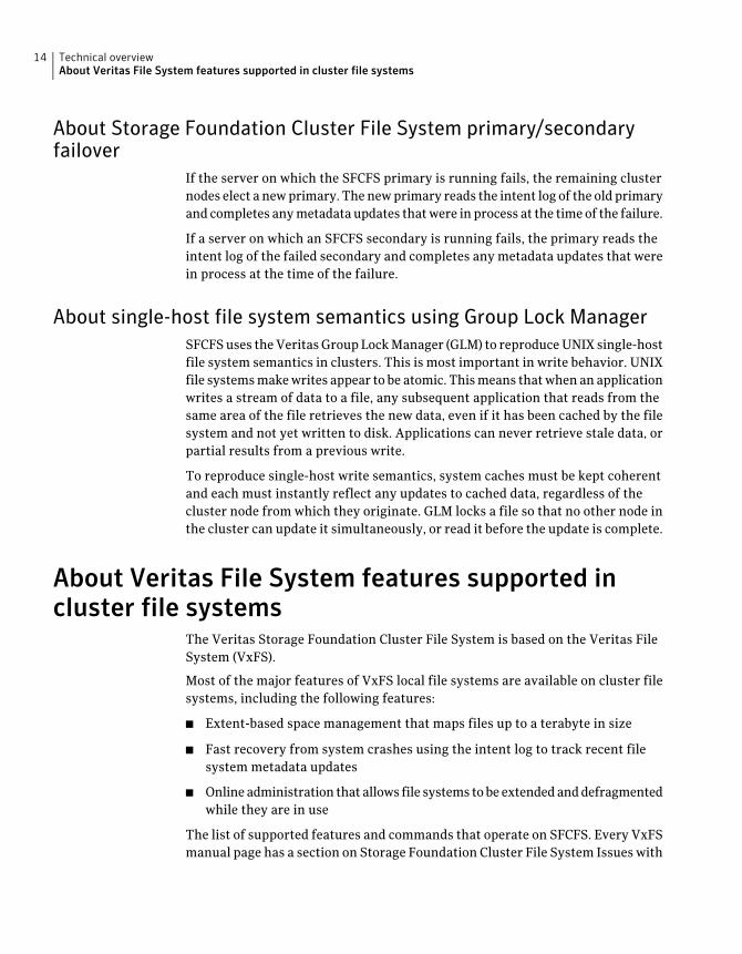
About Veritas File System features supported incluster file systems
The Veritas Storage Foundation Cluster File System is based on the Veritas FileSystem (VxFS).
Most of the major features of VxFS local file systems are available on cluster filesystems, including the following features:
■ Extent-based space management that maps files up to a terabyte in size
■ Fast recovery from system crashes using the intent log to track recent filesystem metadata updates
■ Online administration that allows file systems to be extended and defragmentedwhile they are in use
The list of supported features and commands that operate on SFCFS. Every VxFSmanual page has a section on Storage Foundation Cluster File System Issues with
Technical overviewAbout Veritas File System features supported in cluster file systems
14
information on whether the command functions on a cluster-mounted file systemand indicates any difference in behavior from local mounted file systems.
See the Veritas Storage Foundation Cluster File System Release Notes.
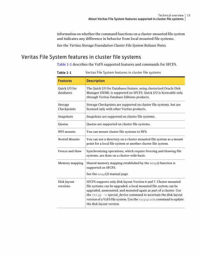
Veritas File System features in cluster file systemsTable 1-1 describes the VxFS supported features and commands for SFCFS.
Table 1-1 Veritas File System features in cluster file systems
DescriptionFeatures
The Quick I/O for Databases feature, using clusterized Oracle DiskManager (ODM), is supported on SFCFS. Quick I/O is licensable onlythrough Veritas Database Editions products.
Quick I/O fordatabases
Storage Checkpoints are supported on cluster file systems, but arelicensed only with other Veritas products.
StorageCheckpoints
Snapshots are supported on cluster file systems.Snapshots
Quotas are supported on cluster file systems.Quotas
You can mount cluster file systems to NFS.NFS mounts
You can use a directory on a cluster mounted file system as a mountpoint for a local file system or another cluster file system.
Nested Mounts
Synchronizing operations, which require freezing and thawing filesystems, are done on a cluster-wide basis.
Freeze and thaw
Shared memory mapping established by the mmap() function issupported on SFCFS.
See the mmap(2) manual page.
Memory mapping
SFCFS supports only disk layout Version 6 and 7. Cluster mountedfile systems can be upgraded, a local mounted file system can beupgraded, unmounted, and mounted again as part of a cluster. Usethe fstyp -v special_device command to ascertain the disk layoutversion of a VxFS file system. Use thevxupgrade command to updatethe disk layout version.
Disk layoutversions
15Technical overviewAbout Veritas File System features supported in cluster file systems
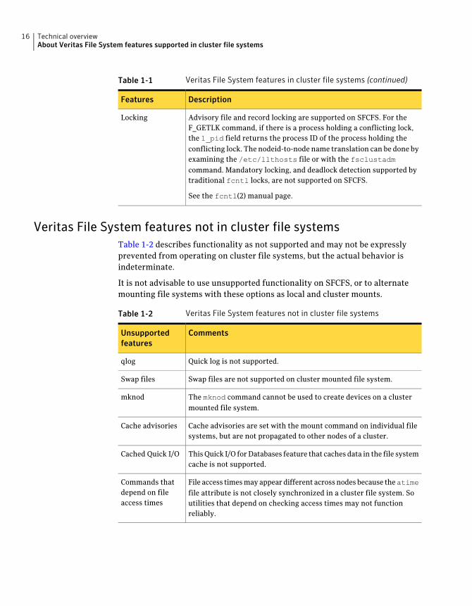
Table 1-1 Veritas File System features in cluster file systems (continued)
DescriptionFeatures
Advisory file and record locking are supported on SFCFS. For theF_GETLK command, if there is a process holding a conflicting lock,the l_pid field returns the process ID of the process holding theconflicting lock. The nodeid-to-node name translation can be done byexamining the /etc/llthosts file or with the fsclustadmcommand. Mandatory locking, and deadlock detection supported bytraditional fcntl locks, are not supported on SFCFS.
See the fcntl(2) manual page.
Locking
Veritas File System features not in cluster file systemsTable 1-2 describes functionality as not supported and may not be expresslyprevented from operating on cluster file systems, but the actual behavior isindeterminate.
It is not advisable to use unsupported functionality on SFCFS, or to alternatemounting file systems with these options as local and cluster mounts.
Table 1-2 Veritas File System features not in cluster file systems
CommentsUnsupportedfeatures
Quick log is not supported.qlog
Swap files are not supported on cluster mounted file system.Swap files
The mknod command cannot be used to create devices on a clustermounted file system.
mknod
Cache advisories are set with the mount command on individual filesystems, but are not propagated to other nodes of a cluster.
Cache advisories
This Quick I/O for Databases feature that caches data in the file systemcache is not supported.
Cached Quick I/O
File access times may appear different across nodes because theatimefile attribute is not closely synchronized in a cluster file system. Soutilities that depend on checking access times may not functionreliably.
Commands thatdepend on fileaccess times
Technical overviewAbout Veritas File System features supported in cluster file systems
16
Storage Foundation Cluster File System benefits andapplications
This section describes the SFCFS benefits and applications.
This section includes the following topics:
■ How Storage Foundation Cluster File System works
■ When to use Storage Foundation Cluster File System
How Storage Foundation Cluster File System worksSFCFS simplifies or eliminates system administration tasks that result from thefollowing hardware limitations:
■ The SFCFS single file system image administrative model simplifiesadministration by making all file system management operations and resizingand reorganization (defragmentation) can be performed from any node.
■ Because all servers in a cluster have access to SFCFS cluster-shareable filesystems, keeping data consistent across multiple servers is automatic. Allcluster nodes have access to the same data, and all data is accessible by allservers using single server file system semantics.
■ Because all files can be accessed by all servers, applications can be allocatedto servers to balance load or meet other operational requirements. Similarly,failover becomes more flexible because it is not constrained by dataaccessibility.
■ Because each SFCFS file system can be on any node in the cluster, the filesystem recovery portion of failover time in an n-node cluster can be reducedby a factor ofn by distributing the file systems uniformly across cluster nodes.
■ Enterprise RAID subsystems can be used more effectively because all of theircapacity can be mounted by all servers, and allocated by using administrativeoperations instead of hardware reconfigurations.
■ Larger volumes with wider striping improve application I/O load balancing.Not only is the I/O load of each server spread across storage resources, butwith SFCFS shared file systems, the loads of all servers are balanced againsteach other.
■ Extending clusters by adding servers is easier because each new server’s storageconfiguration does not need to be set up—new servers simply adopt thecluster-wide volume and file system configuration.
17Technical overviewStorage Foundation Cluster File System benefits and applications
■ The clusterized Oracle Disk Manager (ODM) feature that makes file-baseddatabases perform as well as raw partition-based databases is available toapplications running in a cluster.
When to use Storage Foundation Cluster File SystemYou should use SFCFS for any application that requires the sharing of files, suchas for home directories and boot server files, Web pages, and for cluster-readyapplications. SFCFS is also applicable when you want highly available standbydata, in predominantly read-only environments where you just need to accessdata, or when you do not want to rely on NFS for file sharing.
Almost all applications can benefit from SFCFS. Applications that are not“cluster-aware” can operate on and access data from anywhere in a cluster. Ifmultiple cluster applications running on different servers are accessing data ina cluster file system, overall system I/O performance improves due to the loadbalancing effect of having one cluster file system on a separate underlying volume.This is automatic; no tuning or other administrative action is required.
Many applications consist of multiple concurrent threads of execution that couldrun on different servers if they had a way to coordinate their data accesses. SFCFSprovides this coordination. Such applications can be made cluster-aware allowingtheir instances to co-operate to balance client and data access load, and therebyscale beyond the capacity of any single server. In such applications, SFCFS providesshared data access, enabling application-level load balancing across cluster nodes.
SFCFS provides the following features:
■ For single-host applications that must be continuously available, SFCFS canreduce application failover time because it provides an already-running filesystem environment in which an application can restart after a server failure.
■ For parallel applications, such as distributed database management systemsand Web servers, SFCFS provides shared data to all application instancesconcurrently. SFCFS also allows these applications to grow by the addition ofservers, and improves their availability by enabling them to redistribute loadin the event of server failure simply by reassigning network addresses.
■ For workflow applications, such as video production, in which very large filesare passed from station to station, the SFCFS eliminates time consuming anderror prone data copying by making files available at all stations.
■ For backup, the SFCFS can reduce the impact on operations by running on aseparate server, accessing data in cluster-shareable file systems.
The following are examples of applications and how they might work with SFCFS:
■ Using Storage Foundation Cluster File System on file servers
Technical overviewStorage Foundation Cluster File System benefits and applications
18
Two or more servers connected in a cluster configuration (that is, connectedto the same clients and the same storage) serve separate file systems. If oneof the servers fails, the other recognizes the failure, recovers, assumes theprimaryship, and begins responding to clients using the failed server’s IPaddresses.
■ Using Storage Foundation Cluster File System on web serversWeb servers are particularly suitable to shared clustering because theirapplication is typically read-only. Moreover, with a client load balancing frontend, a Web server cluster’s capacity can be expanded by adding a server andanother copy of the site. A SFCFS-based cluster greatly simplifies scaling andadministration for this type of application.
19Technical overviewStorage Foundation Cluster File System benefits and applications

Technical overviewStorage Foundation Cluster File System benefits and applications
20
Storage Foundation ClusterFile System architecture
This chapter includes the following topics:
■ Storage Foundation Cluster File System architecture overview
■ When the Storage Foundation Cluster File System primary fails
■ About Veritas Volume Manager cluster functionality
Storage Foundation Cluster File System architectureoverview
SFCFS includes Veritas Cluster Server (VCS) and Veritas Volume Manager (VxVM).The Veritas Cluster Server (VCS) provides the communication, configuration, andmembership services required to create a cluster. VCS is the first componentinstalled and configured to set up a cluster file system.
About Veritas Cluster Server architectureThe Group Membership and Atomic Broadcast (GAB) and Low Latency Transport(LLT) are VCS-specific protocols implemented directly on an Ethernet data link.They run on redundant data links that connect the nodes in a cluster. VCS requiresredundant cluster communication links to avoid single points of failure.
GAB provides membership and messaging for the cluster and its applications.GAB membership also provides orderly startup and shutdown of a cluster. Thefile /etc/gabtab is used to configure GAB. Configuration is done with thegabconfig command. For example, the -n option of the command specifies thenumber of nodes in the cluster. GAB is configured automatically when you run
2Chapter
the VCS installation script, but you may have to reconfigure GAB when addingnodes to a cluster.
See the gabconfig(1M) manual page.
LLT provides kernel-to-kernel communications and monitors networkcommunications. The LLT files /etc/llthosts and /etc/llttab are configuredto set system IDs within a cluster, set cluster IDs for multiple clusters, and tunenetwork parameters such as heartbeat frequency. LLT is implemented so thatevents such as state changes are reflected quickly, which in turn enables fastresponses.
As with GAB, LLT is configured automatically when you run the VCS installationscript. The file /etc/llttab contains information you provide during installation.You may also have to reconfigure LLT when adding nodes to a cluster.
See the llttab(4) manual page.
See the Veritas Cluster Server User’s Guide.
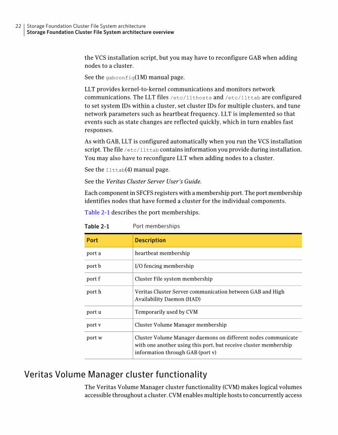
Each component in SFCFS registers with a membership port. The port membershipidentifies nodes that have formed a cluster for the individual components.
Table 2-1 describes the port memberships.
Table 2-1 Port memberships
DescriptionPort
heartbeat membershipport a
I/O fencing membershipport b
Cluster File system membershipport f
Veritas Cluster Server communication between GAB and HighAvailability Daemon (HAD)
port h
Temporarily used by CVMport u
Cluster Volume Manager membershipport v
Cluster Volume Manager daemons on different nodes communicatewith one another using this port, but receive cluster membershipinformation through GAB (port v)
port w
Veritas Volume Manager cluster functionalityThe Veritas Volume Manager cluster functionality (CVM) makes logical volumesaccessible throughout a cluster. CVM enables multiple hosts to concurrently access
Storage Foundation Cluster File System architectureStorage Foundation Cluster File System architecture overview
22
the logical volumes under its control. A VxVM cluster comprises nodes sharinga set of devices. The nodes are connected across a network. If one node fails, othernodes can access the devices. The VxVM cluster feature presents the same logicalview of the device configurations, including changes, on all nodes. You configureCVM shared storage after VCS sets up a cluster configuration.
When the Storage Foundation Cluster File Systemprimary fails
If the server on which the SFCFS primary is running fails, the remaining clusternodes elect a new primary. The new primary reads the file system intent log andcompletes any metadata updates that were in process at the time of the failure.Application I/O from other nodes may block during this process and cause a delay.When the file system is again consistent, application processing resumes.
Because nodes using a cluster file system in secondary mode do not update filesystem metadata directly, failure of a secondary node does not require metadatarepair. SFCFS recovery from secondary node failure is therefore faster than fromprimary node failure.
See “Distribute a load on a cluster ” on page 27.
About Storage Foundation Cluster File System and the Group LockManager
SFCFS uses the Veritas Group Lock Manager (GLM) to reproduce UNIX single-hostfile system semantics in clusters. UNIX file systems make writes appear atomic.This means when an application writes a stream of data to a file, a subsequentapplication reading from the same area of the file retrieves the new data, even ifit has been cached by the file system and not yet written to disk. Applicationscannot retrieve stale data or partial results from a previous write.
To reproduce single-host write semantics, system caches must be kept coherent,and each must instantly reflect updates to cached data, regardless of the nodefrom which they originate.
About asymmetric mountsA VxFS file system mounted with the mount -o cluster option is a cluster, orshared, mount, as opposed to a non-shared or local mount. A file system mountedin shared mode must be on a VxVM shared volume in a cluster environment. Alocal mount cannot be remounted in shared mode and a shared mount cannot be
23Storage Foundation Cluster File System architectureWhen the Storage Foundation Cluster File System primary fails
remounted in local mode. File systems in a cluster can be mounted with differentread/write options. These are called asymmetric mounts.
Asymmetric mounts allow shared file systems to be mounted with differentread/write capabilities. One node in the cluster can mount read/write, while othernodes mount read-only.
You can specify the cluster read-write (crw) option when you first mount the filesystem, or the options can be altered when doing a remount (mount -o remount).
See the mount_vxfs(1M) manual page.
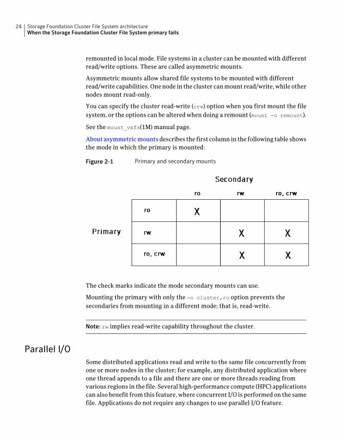
About asymmetric mounts describes the first column in the following table showsthe mode in which the primary is mounted:
Figure 2-1 Primary and secondary mounts
The check marks indicate the mode secondary mounts can use.
Mounting the primary with only the -o cluster,ro option prevents thesecondaries from mounting in a different mode; that is, read-write.
Note: rw implies read-write capability throughout the cluster.
Parallel I/OSome distributed applications read and write to the same file concurrently fromone or more nodes in the cluster; for example, any distributed application whereone thread appends to a file and there are one or more threads reading fromvarious regions in the file. Several high-performance compute (HPC) applicationscan also benefit from this feature, where concurrent I/O is performed on the samefile. Applications do not require any changes to use parallel I/O feature.
Storage Foundation Cluster File System architectureWhen the Storage Foundation Cluster File System primary fails
24
Traditionally, the entire file is locked to perform I/O to a small region. To supportparallel I/O, SFCFS locks ranges in a file that correspond to an I/O request. Thegranularity of the locked range is a page.Two I/O requests conflict if at least oneis a write request, and the I/O range of the request overlaps the I/O range of theother.
The parallel I/O feature enables I/O to a file by multiple threads concurrently, aslong as the requests do not conflict. Threads issuing concurrent I/O requests couldbe executing on the same node, or on a different node in the cluster.
An I/O request that requires allocation is not executed concurrently with otherI/O requests. Note that when a writer is extending the file and readers are laggingbehind, block allocation is not necessarily done for each extending write.
If the file size can be predetermined, the file can be preallocated to avoid blockallocations during I/O. This improves the concurrency of applications performingparallel I/O to the file. Parallel I/O also avoids unnecessary page cache flushesand invalidations using range locking, without compromising the cache coherencyacross the cluster.
For applications that update the same file from multiple nodes, the -nomtime
mount option provides further concurrency. Modification and change times ofthe file are not synchronized across the cluster, which eliminates the overheadof increased I/O and locking. The timestamp seen for these files from a node maynot have the time updates that happened in the last 60 seconds.
Storage Foundation Cluster File System namespaceThe mount point name must remain the same for all nodes mounting the samecluster file system. This is required for the VCS mount agents (online, offline, andmonitoring) to work correctly.
Storage Foundation Cluster File System backup strategiesThe same backup strategies used for standard VxFS can be used with SFCFSbecause the APIs and commands for accessing the namespace are the same. FileSystem checkpoints provide an on-disk, point-in-time copy of the file system.Because performance characteristics of a checkpointed file system are better incertain I/O patterns, they are recommended over file system snapshots (describedbelow) for obtaining a frozen image of the cluster file system.
File System snapshots are another method of a file system on-disk frozen image.The frozen image is non-persistent, in contrast to the checkpoint feature. Asnapshot can be accessed as a read-only mounted file system to perform efficientonline backups of the file system. Snapshots implement “copy-on-write” semanticsthat incrementally copy data blocks when they are overwritten on the snapped
25Storage Foundation Cluster File System architectureWhen the Storage Foundation Cluster File System primary fails
file system. Snapshots for cluster file systems extend the same copy-on-writemechanism for the I/O originating from any cluster node.
Mounting a snapshot filesystem for backups increases the load on the systembecause of the resources used to perform copy-on-writes and to read data blocksfrom the snapshot. In this situation, cluster snapshots can be used to do off-hostbackups. Off-host backups reduce the load of a backup application from theprimary server. Overhead from remote snapshots is small when compared tooverall snapshot overhead. Therefore, running a backup application by mountinga snapshot from a relatively less loaded node is beneficial to overall clusterperformance.
The following are several characteristics of a cluster snapshot:
■ A snapshot for a cluster mounted file system can be mounted on any node ina cluster. The file system can be a primary, secondary, or secondary-only. Astable image of the file system is provided for writes from any node.
■ Multiple snapshots of a cluster file system can be mounted on the same ordifferent cluster node.
■ A snapshot is accessible only on the node mounting a snapshot. The snapshotdevice cannot be mounted on two nodes simultaneously.
■ The device for mounting a snapshot can be a local disk or a shared volume. Ashared volume is used exclusively by a snapshot mount and is not usable fromother nodes as long as the snapshot is active on that device.
■ On the node mounting a snapshot, the snapped file system cannot beunmounted while the snapshot is mounted.
■ A SFCFS snapshot ceases to exist if it is unmounted or the node mounting thesnapshot fails. However, a snapshot is not affected if a node leaves or joinsthe cluster.
■ A snapshot of a read-only mounted file system cannot be taken. It is possibleto mount snapshot of a cluster file system only if the snapped cluster filesystem is mounted with the crw option.
In addition to file-level frozen images, there are volume-level alternatives availablefor shared volumes using mirror split and rejoin. Features such as Fast MirrorResync and Space Optimized snapshot are also available.
See the Veritas VolumeManager System Administrator’s Guide.
Synchronize time on Cluster File SystemsSFCFS requires that the system clocks on all nodes are synchronized using someexternal component such as the Network Time Protocol (NTP) daemon. If the
Storage Foundation Cluster File System architectureWhen the Storage Foundation Cluster File System primary fails
26
nodes are not in sync, timestamps for creation (ctime) and modification (mtime)may not be consistent with the sequence in which operations actually happened.
Distribute a load on a clusterYou can use the fsclustadm to designate a SFCFS primary. The fsclustadm
setprimary mount point can be used to change the primary. This change to theprimary is not persistent across unmounts or reboots. The change is in effect aslong as one or more nodes in the cluster have the file system mounted. The primaryselection policy can also be defined by a VCS attribute associated with the SFCFSmount resource.
For example, if you have eight file systems and four nodes, designating two filesystems per node as the primary is beneficial. The first node that mounts a filesystem becomes the primary for that file system.
File system tuneablesTuneable parameters are updated at the time of mount using the tunefstab fileor vxtunefs command. The file system tunefs parameters are set to be identicalon all nodes by propagating the parameters to each cluster node. When the filesystem is mounted on the node, the tunefs parameters of the primary node areused. The tunefstab file on the node is used if this is the first node to mount thefile system. Symantec recommends that this file be identical on each node.
Split-brain and jeopardy handlingA split-brain occurs when the cluster membership view differs among the clusternodes, increasing the chance of data corruption. Membership change also occurswhen all private-link cluster interconnects fail simultaneously, or when a nodeis unable to respond to heartbeat messages.With I/O fencing, the potential fordata corruption is eliminated. I/O fencing requires disks that support SCSI-3 PGR.
Jeopardy stateIn the absence of I/O fencing, SFCFS installation requires two heartbeat links.When a node is down to a single heartbeat connection, SFCFS can no longerdiscriminate between loss of a system and loss of the final network connection.This state is defined as jeopardy.
SFCFS employs jeopardy to prevent data corruption following a split-brain.
In certain following scenarios, the possibility of data corruption remains:
■ All links go down simultaneously.
27Storage Foundation Cluster File System architectureWhen the Storage Foundation Cluster File System primary fails
■ A node hangs and is unable to respond to heartbeat messages.
To eliminate the chance of data corruption in these scenarios, I/O fencing isrequired. With I/O fencing, the jeopardy state does not require special handlingby the SFCFS stack.
Jeopardy handlingFor installations that do not support SCSI-3 PGR, potential split-brain conditionsare safeguarded by jeopardy handling. If any cluster node fails following a jeopardystate notification, the cluster file system mounted on the failed nodes is disabled.If a node fails after the jeopardy state notification, all cluster nodes also leave theshared disk group membership.
Recover from jeopardyThe disabled file system can be restored by a force unmount and the resource canbe brought online without rebooting, which also brings the shared disk groupresource online. Note that if the jeopardy condition is not fixed, the nodes aresusceptible to leaving the cluster again on subsequent node failure.
See the Veritas Cluster Server User’s Guide.
FencingWith the use of I/O enabled fencing, all remaining cases with the potential tocorrupt data (for which jeopardy handling cannot protect) are addressed.
See “I/O fencing” on page 81.
Single network link and reliabilityCertain environments may prefer using a single private link or a pubic networkfor connecting nodes in a cluster, despite the loss of redundancy for dealing withnetwork failures. The benefits of this approach include simpler hardware topologyand lower costs; however, there is obviously a tradeoff with high availability.
For the above environments, SFCFS provides the option of a single private link,or using the public network as the private link if I/O fencing is present. I/O fencingis used to handle split-brain scenarios. The option for single network is givenduring installation.
See “I/O fencing” on page 81.
Storage Foundation Cluster File System architectureWhen the Storage Foundation Cluster File System primary fails
28
Configuring low priority linkLLT can be configured to use a low-priority network link as a backup to normalheartbeat channels. Low-priority links are typically configured on the customer’spublic or administrative network. This typically results in a completely differentnetwork infrastructure than the cluster private interconnect, and reduces thechance of a single point of failure bringing down all links. The low-priority linkis not used for cluster membership traffic until it is the only remaining link. Innormal operation, the low-priority link carries only heartbeat traffic for clustermembership and link state maintenance. The frequency of heartbeats drops 50percent to reduce network overhead. When the low-priority link is the onlyremaining network link, LLT also switches over all cluster status traffic. Followingrepair of any configured private link, LLT returns cluster status traffic to thehigh-priority link.
LLT links can be added or removed while clients are connected. Shutting downGAB or the high-availability daemon, had, is not required.
To add a link
■ To add a link, type the following command:# lltconfig -d device -t tag
To remove a link
■ To remove a link, type the following command:# lltconfig -u tag
Changes take effect immediately and are lost on the next reboot. For changes tospan reboots you must also update /etc/llttab.
Note: LLT clients do not recognize the difference unless only one link is availableand GAB declares jeopardy.
I/O error handling policyI/O errors can occur for several reasons, including failures of Fibre Channel link,host-bus adapters, and disks. SFCFS disables the file system on the nodeencountering I/O errors. The file system remains available from other nodes.
After the hardware error is fixed (for example, the Fibre Channel link isreestablished), the file system can be force unmounted and the mount resourcecan be brought online from the disabled node to reinstate the file system.
29Storage Foundation Cluster File System architectureWhen the Storage Foundation Cluster File System primary fails
About Veritas Volume Manager cluster functionalityVeritas Volume Manager cluster functionality (CVM) allows up to 32 nodes in acluster to simultaneously access and manage a set of disks under VxVM control(VM disks). The same logical view of the disk configuration and any changes areavailable on each node. When the cluster functionality is enabled, all cluster nodescan share VxVM objects. Features provided by the base volume manager, such asmirroring, fast mirror resync and dirty region logging are also supported in thecluster environment.
Note: RAID-5 volumes are not supported on a shared disk group.
To implement cluster functionality, VxVM works together with the cluster monitordaemon provided by the host operating system or by VCS. The cluster monitorinforms VxVM of changes in cluster membership. Each node starts upindependently and has its own cluster monitor, plus its own copies of the operatingsystem and CVM. When a node joins a cluster it gains access to shared disks. Whena node leaves a cluster, it no longer has access to shared disks. A node joins acluster when the cluster monitor is started on that node.
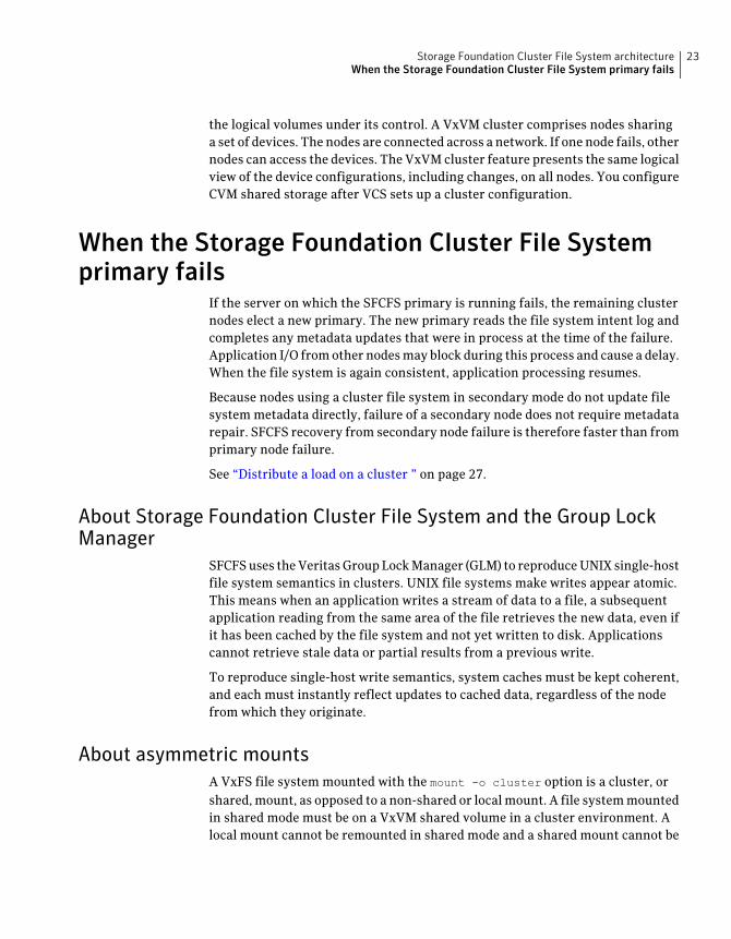
Figure 2-2 illustrates a simple cluster arrangement consisting of four nodes withsimilar or identical hardware characteristics (CPUs, RAM and host adapters), andconfigured with identical software (including the operating system).
The nodes are fully connected by a private network and they are also separatelyconnected to shared external storage (either disk arrays or JBODs: just a bunchof disks) via Fibre Channel. Each node has two independent paths to these disks,which are configured in one or more cluster-shareable disk groups.
The private network allows the nodes to share information about system resourcesand about each other’s state. Using the private network, any node can recognizewhich nodes are currently active, which are joining or leaving the cluster, andwhich have failed. The private network requires at least two communicationchannels to provide redundancy against one of the channels failing. If only onechannel were used, its failure would be indistinguishable from node failure—acondition known as network partitioning.
Storage Foundation Cluster File System architectureAbout Veritas Volume Manager cluster functionality
30
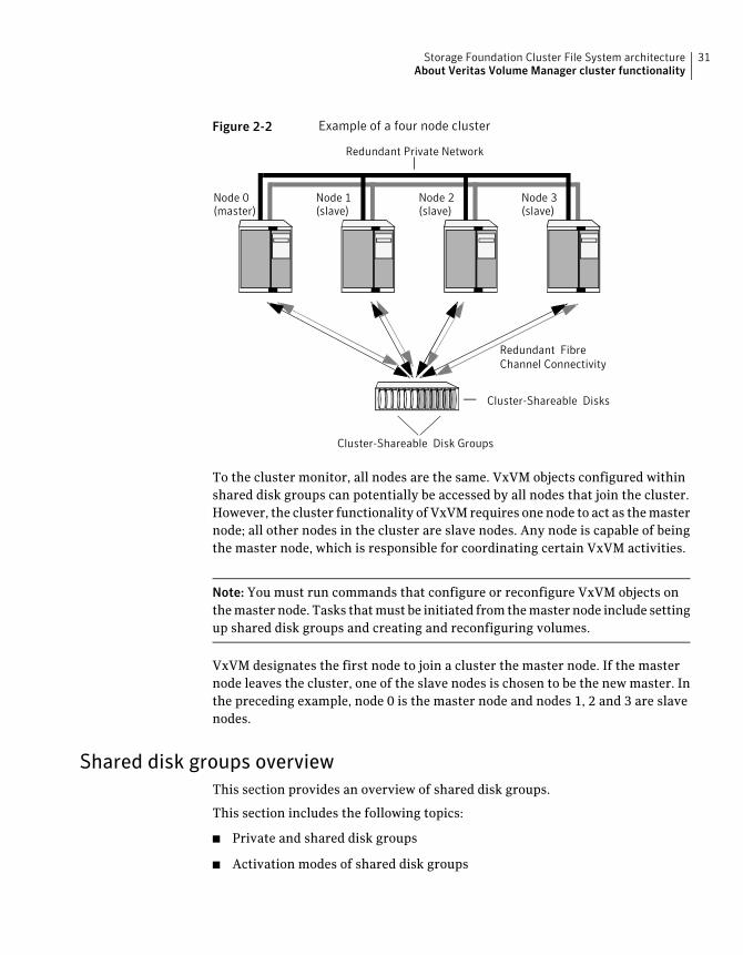
Figure 2-2 Example of a four node cluster
Redundant FibreChannel Connectivity
Cluster-Shareable Disks
Redundant Private Network
Node 0(master)
Node 1(slave)
Node 2(slave)
Node 3(slave)
Cluster-Shareable Disk Groups
To the cluster monitor, all nodes are the same. VxVM objects configured withinshared disk groups can potentially be accessed by all nodes that join the cluster.However, the cluster functionality of VxVM requires one node to act as the masternode; all other nodes in the cluster are slave nodes. Any node is capable of beingthe master node, which is responsible for coordinating certain VxVM activities.
Note: You must run commands that configure or reconfigure VxVM objects onthe master node. Tasks that must be initiated from the master node include settingup shared disk groups and creating and reconfiguring volumes.
VxVM designates the first node to join a cluster the master node. If the masternode leaves the cluster, one of the slave nodes is chosen to be the new master. Inthe preceding example, node 0 is the master node and nodes 1, 2 and 3 are slavenodes.
Shared disk groups overviewThis section provides an overview of shared disk groups.
This section includes the following topics:
■ Private and shared disk groups
■ Activation modes of shared disk groups
31Storage Foundation Cluster File System architectureAbout Veritas Volume Manager cluster functionality
■ Connectivity policy of shared disk groups
■ Limitations of shared disk groups
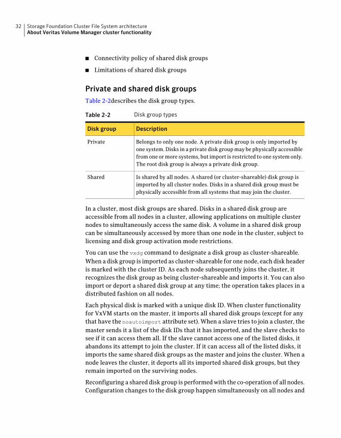
Private and shared disk groupsTable 2-2describes the disk group types.
Table 2-2 Disk group types
DescriptionDisk group
Belongs to only one node. A private disk group is only imported byone system. Disks in a private disk group may be physically accessiblefrom one or more systems, but import is restricted to one system only.The root disk group is always a private disk group.
Private
Is shared by all nodes. A shared (or cluster-shareable) disk group isimported by all cluster nodes. Disks in a shared disk group must bephysically accessible from all systems that may join the cluster.
Shared
In a cluster, most disk groups are shared. Disks in a shared disk group areaccessible from all nodes in a cluster, allowing applications on multiple clusternodes to simultaneously access the same disk. A volume in a shared disk groupcan be simultaneously accessed by more than one node in the cluster, subject tolicensing and disk group activation mode restrictions.
You can use the vxdg command to designate a disk group as cluster-shareable.When a disk group is imported as cluster-shareable for one node, each disk headeris marked with the cluster ID. As each node subsequently joins the cluster, itrecognizes the disk group as being cluster-shareable and imports it. You can alsoimport or deport a shared disk group at any time; the operation takes places in adistributed fashion on all nodes.
Each physical disk is marked with a unique disk ID. When cluster functionalityfor VxVM starts on the master, it imports all shared disk groups (except for anythat have the noautoimport attribute set). When a slave tries to join a cluster, themaster sends it a list of the disk IDs that it has imported, and the slave checks tosee if it can access them all. If the slave cannot access one of the listed disks, itabandons its attempt to join the cluster. If it can access all of the listed disks, itimports the same shared disk groups as the master and joins the cluster. When anode leaves the cluster, it deports all its imported shared disk groups, but theyremain imported on the surviving nodes.
Reconfiguring a shared disk group is performed with the co-operation of all nodes.Configuration changes to the disk group happen simultaneously on all nodes and
Storage Foundation Cluster File System architectureAbout Veritas Volume Manager cluster functionality
32
the changes are identical. Such changes are atomic in nature, which means thatthey either occur simultaneously on all nodes or not at all.
Whether all members of the cluster have simultaneous read and write access toa cluster-shareable disk group depends on its activation mode setting.
See “Activation modes of shared disk groups” on page 33.
The data contained in a cluster-shareable disk group is available as long as at leastone node is active in the cluster. The failure of a cluster node does not affect accessby the remaining active nodes. Regardless of which node accesses acluster-shareable disk group, the configuration of the disk group looks the same.
Note: Applications running on each node can access the data on the VM diskssimultaneously. VxVM does not protect against simultaneous writes to sharedvolumes by more than one node. It is assumed that applications control consistency(by using Veritas Storage Foundation Cluster File System or a distributed lockmanager, for example).
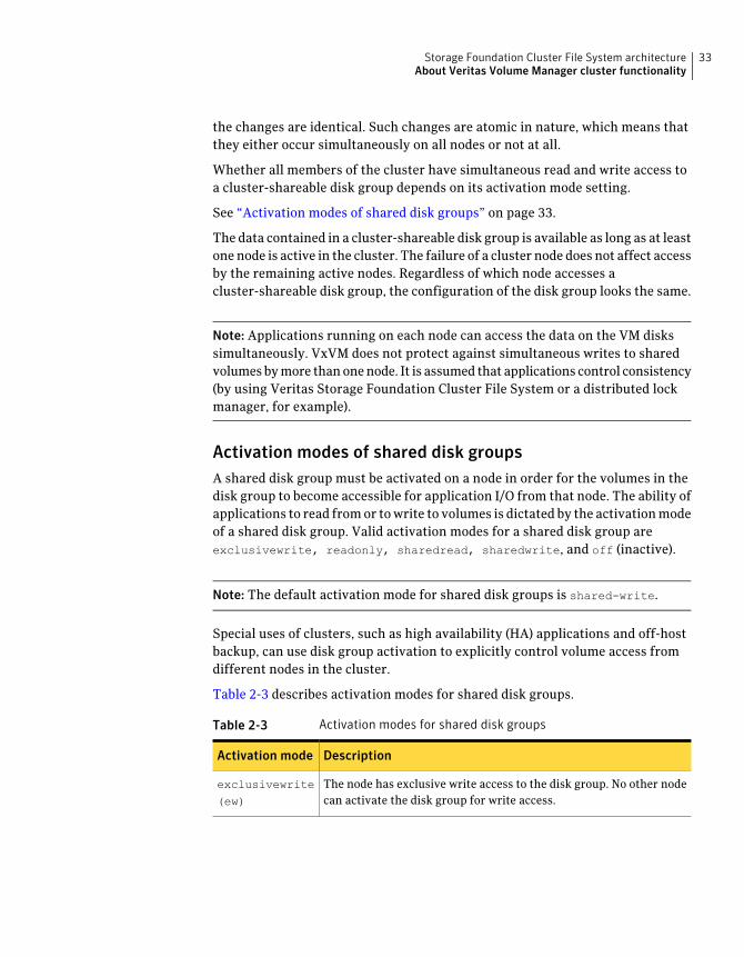
Activation modes of shared disk groupsA shared disk group must be activated on a node in order for the volumes in thedisk group to become accessible for application I/O from that node. The ability ofapplications to read from or to write to volumes is dictated by the activation modeof a shared disk group. Valid activation modes for a shared disk group areexclusivewrite, readonly, sharedread, sharedwrite, and off (inactive).
Note: The default activation mode for shared disk groups is shared-write.
Special uses of clusters, such as high availability (HA) applications and off-hostbackup, can use disk group activation to explicitly control volume access fromdifferent nodes in the cluster.
Table 2-3 describes activation modes for shared disk groups.
Table 2-3 Activation modes for shared disk groups
DescriptionActivation mode
The node has exclusive write access to the disk group. No other nodecan activate the disk group for write access.
exclusivewrite
(ew)
33Storage Foundation Cluster File System architectureAbout Veritas Volume Manager cluster functionality
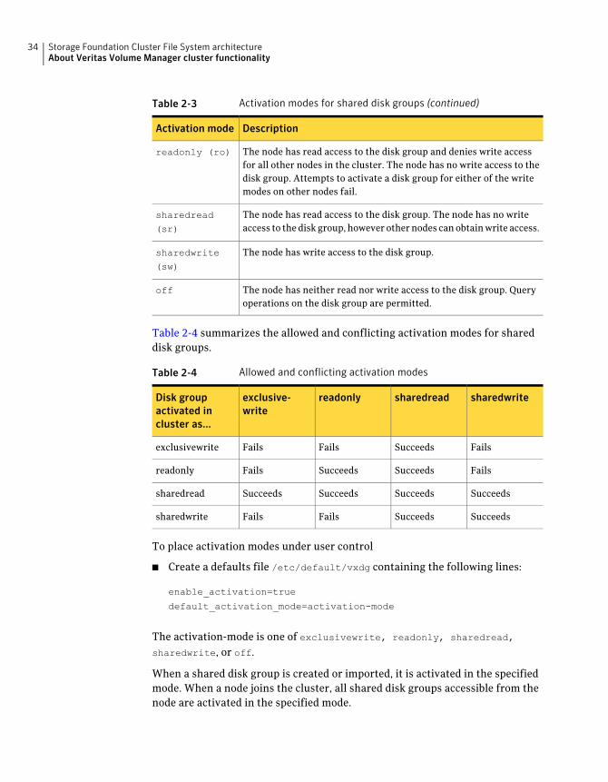
Table 2-3 Activation modes for shared disk groups (continued)
DescriptionActivation mode
The node has read access to the disk group and denies write accessfor all other nodes in the cluster. The node has no write access to thedisk group. Attempts to activate a disk group for either of the writemodes on other nodes fail.
readonly (ro)
The node has read access to the disk group. The node has no writeaccess to the disk group, however other nodes can obtain write access.
sharedread
(sr)
The node has write access to the disk group.sharedwrite
(sw)
The node has neither read nor write access to the disk group. Queryoperations on the disk group are permitted.
off
Table 2-4 summarizes the allowed and conflicting activation modes for shareddisk groups.
Table 2-4 Allowed and conflicting activation modes
sharedwritesharedreadreadonlyexclusive-write
Disk groupactivated incluster as...
FailsSucceedsFailsFailsexclusivewrite
FailsSucceedsSucceedsFailsreadonly
SucceedsSucceedsSucceedsSucceedssharedread
SucceedsSucceedsFailsFailssharedwrite
To place activation modes under user control
■ Create a defaults file /etc/default/vxdg containing the following lines:
enable_activation=true
default_activation_mode=activation-mode
The activation-mode is one of exclusivewrite, readonly, sharedread,
sharedwrite, or off.
When a shared disk group is created or imported, it is activated in the specifiedmode. When a node joins the cluster, all shared disk groups accessible from thenode are activated in the specified mode.
Storage Foundation Cluster File System architectureAbout Veritas Volume Manager cluster functionality
34
The activation mode of a disk group controls volume I/O from different nodes inthe cluster. It is not possible to activate a disk group on a given node if it isactivated in a conflicting mode on another node in the cluster. When enablingactivation using the defaults file, it is recommended that this file be made identicalon all nodes in the cluster. Otherwise, the results of activation are unpredictable.
If the defaults file is edited while the vxconfigd daemon is already running, thevxconfigd process must be restarted for the changes in the defaults file to takeeffect.
If the default activation mode is anything other than off, an activation followinga cluster join, or a disk group creation or import can fail if another node in thecluster has activated the disk group in a conflicting mode.
To display the activation mode for a shared disk group, use the vxdg list
diskgroup command.
You can also use the vxdg command to change the activation mode on a shareddisk group.
See the Veritas VolumeManager Administrator’s Guide.
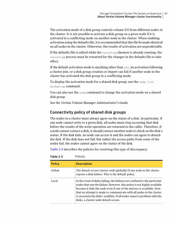
Connectivity policy of shared disk groupsThe nodes in a cluster must always agree on the status of a disk. In particular, ifone node cannot write to a given disk, all nodes must stop accessing that diskbefore the results of the write operation are returned to the caller. Therefore, ifa node cannot contact a disk, it should contact another node to check on the disk’sstatus. If the disk fails, no node can access it and the nodes can agree to detachthe disk. If the disk does not fail, but rather the access paths from some of thenodes fail, the nodes cannot agree on the status of the disk.
Table 2-5 describes the policies for resolving this type of discrepancy.
Table 2-5 Policies
DescriptionPolicy
The detach occurs cluster-wide (globally) if any node in the clusterreports a disk failure. This is the default policy.
Global
In the event of disks failing, the failures are confined to the particularnodes that saw the failure. However, this policy is not highly availablebecause it fails the node even if one of the mirrors is available. Notethat an attempt is made to communicate with all nodes in the clusterto ascertain the disks’ usability. If all nodes report a problem with thedisks, a cluster-wide detach occurs.
Local
35Storage Foundation Cluster File System architectureAbout Veritas Volume Manager cluster functionality
Limitations of shared disk groupsThe cluster functionality of VxVM does not support RAID-5 volumes, or taskmonitoring for cluster-shareable disk groups. These features can, however, beused in private disk groups that are attached to specific nodes of a cluster. Onlinerelayout is supported provided that it does not involve RAID-5 volumes.
The root disk group cannot be made cluster-shareable. It must be private.
Only raw device access may be performed via the cluster functionality of VxVM.It does not support shared access to file systems in shared volumes unless theappropriate software, such as Veritas Storage Foundation Cluster File System, isinstalled and configured.
If a shared disk group contains unsupported objects, deport it and then re-importthe disk group as private on one of the cluster nodes. Reorganize the volumes intolayouts that are supported for shared disk groups, and then deport and re-importthe disk group as shared.
Storage Foundation Cluster File System architectureAbout Veritas Volume Manager cluster functionality
36
Storage Foundation ClusterFile System administration
This chapter includes the following topics:
■ About Storage Foundation Cluster File System administration
■ Veritas Cluster Server overview
■ Veritas Volume Manger cluster functionality overview
■ Storage Foundation Cluster File System overview
■ Storage Foundation Cluster File System administration commands
■ Snapshots on Storage Foundation Cluster File System
■ Adding a node to a cluster
■ Configuring Storage Foundation Cluster File System and Cluster VolumeManager agents on the new node
■ Removing a node from a cluster
About Storage Foundation Cluster File Systemadministration
The Veritas Storage Foundation Cluster File System is a shared file system thatenables multiple hosts to mount and perform file operations concurrently on thesame file. To operate in a cluster configuration, SFCFS requires the integrated setof Veritas products included in the Veritas Storage Foundation Cluster File System.
To configure a cluster, SFCFS requires the Veritas Cluster Server (VCS). VCSsupplies two major components integral to SFCFS. The LLT package provides
3Chapter
node-to-node communications and monitors network communications. The GABpackage provides cluster state, configuration, and membership service, andmonitors the heartbeat links between systems to ensure that they are active. Thereare several other packages supplied by VCS that provide application failoversupport when installing SFCFS HA.
See the Veritas Storage Foundation Cluster File System Installation Guide.
SFCFS also requires the cluster functionality (CVM) of the Veritas Volume Manager(VxVM) to create the shared volumes necessary for mounting cluster file systems.
Note: To install and administer cluster file systems, you should have a workingknowledge of VxVM. To install and administer application failover functionality,you should have a working knowledge of VCS. For more information on theseproducts, refer to the Veritas Volume Manager and Veritas Cluster Serverdocumentation. The user guides for Volume Manager are available in the/opt/VRTSvmdoc directory after you install the Storage Foundation packages. Theuser guides for VCS are available in the /opt/VRTSvcsdcdirectory after you installthe Storage Foundation Cluster File System HA packages.
Topics in this chapter include:
■ VCS Overview
■ CVM Overview
■ SFCFS Overview
■ SFCFS Administration
■ Snapshots on SFCFS
Veritas Cluster Server overviewThe Veritas Cluster Server (VCS) provides the communication, configuration, andmembership services required to create a cluster. VCS is the first componentinstalled and configured to set up a cluster file system.
Group membership and atomic broadcast (GAB) and Low Latency Transport (LLT)are VCS-specific protocols implemented directly on an Ethernet data link or on aFibre Channel fabric. Both GAB and LLT run over redundant data links that connectall the servers in a cluster. VCS requires redundant cluster communication linksto minimize the possibility of cluster failure due to the failure of a singlecommunication link.
Storage Foundation Cluster File System administrationVeritas Cluster Server overview
38
About Group Membership and Atomic BroadcastGroup Membership and Atomic Broadcast (GAB) provides membership andmessaging service, both for the cluster as a whole and for groups of applicationsrunning it. The GAB membership service provides orderly startup and shutdownof a cluster.
The file /etc/gabtab is used to configure GAB. Configuration is done with thegabconfig command. For example, the -n option of the command specifies thenumber of nodes in the cluster. GAB is configured automatically when you runthe VCS installation script, but you may have to reconfigure GAB when you adda node to a cluster.
See the gabconfig(1M) manual page.
About Low Latency TransportLow Latency Transport (LLT) provides kernel-to-kernel communications andmonitors network communications. The LLT files/etc/llthostsand/etc/llttabcan be configured to set system IDs within a cluster, set cluster IDs for multipleclusters, and tune network parameters such as heartbeat frequency. LLT isimplemented so that events such as state changes are reflected quickly, which inturn enables fast responses.
As with GAB, LLT is configured automatically when you run the VCS installationscript. The file /etc/llttab contains information derived from what you inputduring installation. You may also have to reconfigure LLT when you add a nodeto a cluster.
See the llttab(4) manual page.
Veritas VolumeManger cluster functionality overviewThe cluster functionality (CVM) of the Veritas Volume Manager allows multiplehosts to concurrently access and manage a given set of logical devices under VxVMcontrol. A VxVM cluster is a set of hosts sharing a set of devices; each host is anode in the cluster. The nodes are connected across a network. If one node fails,other nodes can still access the devices. The VxVM cluster feature presents thesame logical view of the device configurations, including changes, on all nodes.
You configure CVM shared storage after VCS sets up a cluster configuration.
See “About Veritas Volume Manager cluster functionality administration”on page 105.
See the Veritas VolumeManager Administrator’s Guide.
39Storage Foundation Cluster File System administrationVeritas Volume Manger cluster functionality overview
Storage Foundation Cluster File System overviewA file system cluster consists of one primary, and up to 31 secondaries. Theprimary-secondary terminology applies to one file system, not to a specific node(or hardware platform). So it is possible to have the same cluster node be primaryfor one shared file system, while at the same time it is secondary for anothershared file system. Such distribution of file system primaryship to balance theload on a cluster is a recommended administrative policy.
See “Distribute the load on a Cluster” on page 45.
For CVM, a single cluster node is the master for all shared disk groups and sharedvolumes in the cluster.
Number of parallel fsck threads to run during recovery is tunableIn previous releases the number of parallel fsck thread that could be active duringrecovery was set to 4. If a node failed over 12 file systems, log replay for the 12file systems will not complete at the same time. The maximum parallelism wasrestricted to 4. The number was set to 4 since parallel replay of a large numberof file systems would put memory pressure on smaller systems with less memory.However, on larger systems the restriction of 4 parallel processes replaying is notnecessary. In this release this value is either dependent on the number of CPUsin the system, but you can get the value within given limits.
To set the number of parallel fsck thread
■ On all nodes in the cluster, edit the/opt/VRTSvcs/bin/CFSfsckd/CFSfsckd.envfile and set FSCKD_OPTS="-n N".
where N is the number of parallel fsck threads that the system runs.
Cluster and shared mountsA VxFS file system that is mounted with the mount -o cluster option is calleda cluster or shared mount, as opposed to a non-shared or local mount. A file systemmounted in shared mode must be on a VxVM shared volume in a clusterenvironment. A local mount cannot be remounted in shared mode and a sharedmount cannot be remounted in local mode. File systems in a cluster can be mountedwith different read-write options. These are called asymmetric mounts.
Determining or giving primaryshipBoth primary and secondary nodes handle their metadata intent logging for thecluster file system. The first node of a cluster file system to mount is called theprimary node. Other nodes are called secondary nodes. If a primary node fails, an
Storage Foundation Cluster File System administrationStorage Foundation Cluster File System overview
40
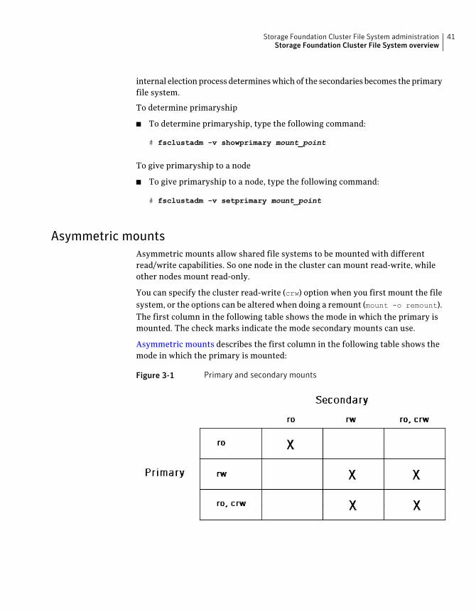
internal election process determines which of the secondaries becomes the primaryfile system.
To determine primaryship
■ To determine primaryship, type the following command:
# fsclustadm -v showprimary mount_point
To give primaryship to a node
■ To give primaryship to a node, type the following command:
# fsclustadm -v setprimary mount_point
Asymmetric mountsAsymmetric mounts allow shared file systems to be mounted with differentread/write capabilities. So one node in the cluster can mount read-write, whileother nodes mount read-only.
You can specify the cluster read-write (crw) option when you first mount the filesystem, or the options can be altered when doing a remount (mount -o remount).The first column in the following table shows the mode in which the primary ismounted. The check marks indicate the mode secondary mounts can use.
Asymmetric mounts describes the first column in the following table shows themode in which the primary is mounted:
Figure 3-1 Primary and secondary mounts
41Storage Foundation Cluster File System administrationStorage Foundation Cluster File System overview
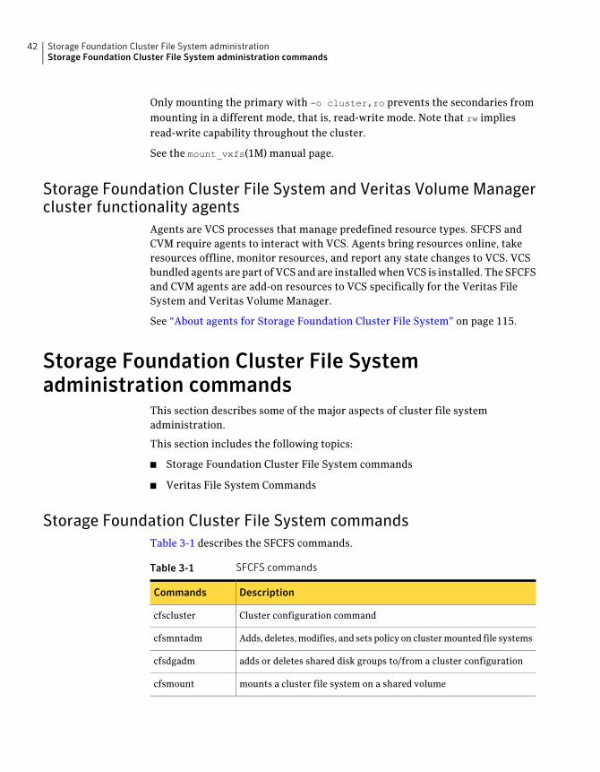
Only mounting the primary with -o cluster,ro prevents the secondaries frommounting in a different mode, that is, read-write mode. Note that rw impliesread-write capability throughout the cluster.
See the mount_vxfs(1M) manual page.
Storage Foundation Cluster File System and Veritas Volume Managercluster functionality agents
Agents are VCS processes that manage predefined resource types. SFCFS andCVM require agents to interact with VCS. Agents bring resources online, takeresources offline, monitor resources, and report any state changes to VCS. VCSbundled agents are part of VCS and are installed when VCS is installed. The SFCFSand CVM agents are add-on resources to VCS specifically for the Veritas FileSystem and Veritas Volume Manager.
See “About agents for Storage Foundation Cluster File System” on page 115.
Storage Foundation Cluster File Systemadministration commands
This section describes some of the major aspects of cluster file systemadministration.
This section includes the following topics:
■ Storage Foundation Cluster File System commands
■ Veritas File System Commands
Storage Foundation Cluster File System commandsTable 3-1 describes the SFCFS commands.
Table 3-1 SFCFS commands
DescriptionCommands
Cluster configuration commandcfscluster
Adds, deletes, modifies, and sets policy on cluster mounted file systemscfsmntadm
adds or deletes shared disk groups to/from a cluster configurationcfsdgadm
mounts a cluster file system on a shared volumecfsmount
Storage Foundation Cluster File System administrationStorage Foundation Cluster File System administration commands
42
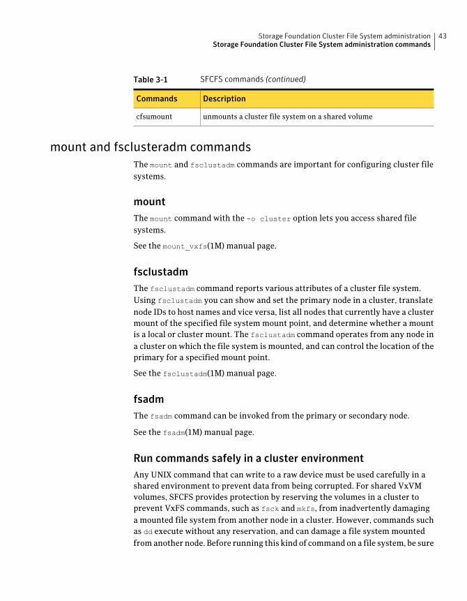
Table 3-1 SFCFS commands (continued)
DescriptionCommands
unmounts a cluster file system on a shared volumecfsumount
mount and fsclusteradm commandsThe mount and fsclustadm commands are important for configuring cluster filesystems.
mountThe mount command with the -o cluster option lets you access shared filesystems.
See the mount_vxfs(1M) manual page.
fsclustadmThe fsclustadm command reports various attributes of a cluster file system.Using fsclustadm you can show and set the primary node in a cluster, translatenode IDs to host names and vice versa, list all nodes that currently have a clustermount of the specified file system mount point, and determine whether a mountis a local or cluster mount. The fsclustadm command operates from any node ina cluster on which the file system is mounted, and can control the location of theprimary for a specified mount point.
See the fsclustadm(1M) manual page.
fsadmThe fsadm command can be invoked from the primary or secondary node.
See the fsadm(1M) manual page.
Run commands safely in a cluster environmentAny UNIX command that can write to a raw device must be used carefully in ashared environment to prevent data from being corrupted. For shared VxVMvolumes, SFCFS provides protection by reserving the volumes in a cluster toprevent VxFS commands, such as fsck and mkfs, from inadvertently damaginga mounted file system from another node in a cluster. However, commands suchas dd execute without any reservation, and can damage a file system mountedfrom another node. Before running this kind of command on a file system, be sure
43Storage Foundation Cluster File System administrationStorage Foundation Cluster File System administration commands
the file system is not mounted on a cluster. You can run the mount command tosee if a file system is a shared or local mount.
Time synchronization for Cluster File SystemsSFCFS requires that the system clocks on all nodes are synchronized using someexternal component such as the Network Time Protocol (NTP) daemon. If thenodes are not in sync, timestamps for creation (ctime) and modification (mtime)may not be consistent with the sequence in which operations actually happened.
Growing a Storage Foundation Cluster File SystemThere is a master node for CVM as well as a primary for SFCFS. When growing afile system, you grow the volume from the CVM master, and then grow the filesystem from any SFCFS node. The CVM master and the SFCFS node can be differentnodes.
To determine the primary file system in a cluster
■ To determine the primary file system in a cluster, type the following command:
# fsclustadm -v showprimary mount_point
To determine that the current node is the master CVM node
■ To determine if the current node is the master CVM node, type the followingcomannd:
# vxdctl -c mode
To actually increase the size of the file system
1 On the master CVM node, type the following command:
# vxassist -g shared_disk_group growto volume_name newlength
2 On any SFCFS node, type the following command:
# fsadm -t vxfs -b newsize -r device_name mount_point
The fstab fileIn the /etc/fstab file, do not specify any cluster file systems to mount-at-bootbecause mounts initiated from fstab occur before cluster configuration begins.For cluster mounts, use the VCS configuration file to determine which file systemsto enable following a reboot.
Storage Foundation Cluster File System administrationStorage Foundation Cluster File System administration commands
44
Distribute the load on a ClusterDistributing the workload in a cluster provides performance and failoveradvantages.
For example, if you have eight file systems and four nodes, designating two filesystems per node as the primary would be beneficial. Primaryship is determinedby which node first mounts the file system. You can also use the fsclustadm todesignate a SFCFS primary. The fsclustadm setprimary command can alsodefine the order in which primaryship is assumed if the current primary fails.After setup, the policy is in effect as long as one or more nodes in the cluster havethe file system mounted.
GUIsUse the Veritas Enterprise Administrator (VEA) for various VxFS functions suchas making and mounting file systems, on both local and cluster file systems.
With SFCFS HA, you can use the VCS Cluster Manager GUI to configure andmonitor SFCFS. The VCS GUI provides log files for debugging LLT and GAB events.
Snapshots onStorage FoundationCluster File SystemA snapshot provides a consistent point-in-time image of a VxFS file system. Asnapshot can be accessed as a read-only mounted file system to perform efficientonline backups of the file system. Snapshots implement copy-on-write semanticsthat incrementally copy data blocks when they are overwritten on the snappedfile system.
See the Veritas File System Administrator’s Guide.
Snapshots for cluster file systems extend the same copy-on-write mechanism forthe I/O originating from any node in the cluster.
Cluster snapshot characteristicsA cluster snapshot has the following characteristics:
■ A snapshot for a cluster mounted file system can be mounted on any node ina cluster. The file system can be a primary, secondary, or secondary-only. Astable image of the file system is provided for writes from any node.
■ Multiple snapshots of a cluster file system can be mounted on the same or adifferent node in a cluster.
■ A snapshot is accessible only on the node mounting a snapshot. The snapshotdevice cannot be mounted on two different nodes simultaneously.
45Storage Foundation Cluster File System administrationSnapshots on Storage Foundation Cluster File System
■ The device for mounting a snapshot can be a local disk or a shared volume. Ashared volume is used exclusively by a snapshot mount and is not usable fromother nodes in a cluster as long as the snapshot is active on that device.
■ On the node mounting a snapshot, the snapped file system cannot beunmounted while the snapshot is mounted.
■ A SFCFS snapshot ceases to exist if it is unmounted or the node mounting thesnapshot fails. A snapshot, however, is not affected if any other node leavesor joins the cluster.
■ A snapshot of a read-only mounted file system cannot be taken. It is possibleto mount snapshot of a cluster file system only if the snapped cluster filesystem is mounted with the crw option.
Performance considerationsMounting a snapshot file system for backup increases the load on the systembecause of the resources used to perform copy-on-writes and to read data blocksfrom the snapshot. In this situation, cluster snapshots can be used to do off-hostbackups. Off-host backups reduce the load of a backup application from theprimary server. Overhead from remote snapshots is small when compared tooverall snapshot overhead. Therefore, running a backup application by mountinga snapshot from a relatively less loaded node is beneficial to overall clusterperformance.
Creating a snapshot on a Storage Foundation Cluster File SystemTo create and mount a snapshot on a two-node cluster using SFCFS administrativeinterface commands.
Storage Foundation Cluster File System administrationSnapshots on Storage Foundation Cluster File System
46
To create a snapshot on a cluster file system
1 To create a VxFS file system on a shared VxVM volume, type the followingcommand:
# mkfs -t vxfs /dev/vx/rdsk/cfsdg/vol1
version 7 layout
104857600 sectors, 52428800 blocks of size 1024, log size 16384
blocks
unlimited inodes, largefiles not supported
52428800 data blocks, 52399152 free data blocks
1600 allocation units of 32768 blocks, 32768 data blocks
2 To mount the file system on all nodes, type the following commands:
# cfsmntadm add cfsdg vol1 /mnt1 all=cluster
# cfsmount /mnt1
The cfsmntadm command adds an entry to the cluster manager configuration,then the cfsmount command mounts the file system on all nodes.
3 Add the snapshot on a previously created volume (snapvol in this example)to the cluster manager configuration. For example:
# cfsmntadm add snapshot cfsdg snapvol /mnt1 /mnt1snap system01=ro
The snapshot of a cluster file system is accessible only on the node where itis created; the snapshot file system itself cannot be cluster mounted.
4 Mount the snapshot, type the following command:
# cfsmount /mnt1snap
5 A snapped file system cannot be unmounted until all of its snapshots areunmounted. Unmount the snapshot before trying to unmount the snappedcluster file system, type the following command:
# cfsumount /mnt1snap
Adding a node to a clusterIf you want to add a new node to a multi-node cluster, first prepare the new systemhardware. Physically connect the new node to the cluster using private networksand attach to any shared storage. Then install the required OS software.
47Storage Foundation Cluster File System administrationAdding a node to a cluster
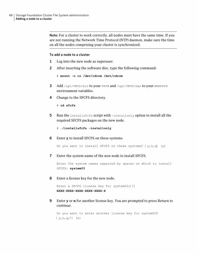
Note: For a cluster to work correctly, all nodes must have the same time. If youare not running the Network Time Protocol (NTP) daemon, make sure the timeon all the nodes comprising your cluster is synchronized.
To add a node to a cluster
1 Log into the new node as superuser.
2 After inserting the software disc, type the following command:
# mount -o ro /dev/cdrom /mnt/cdrom
3 Add /opt/VRTS/bin to your PATH and /opt/VRTS/man to your MANPATHenvironment variables.
4 Change to the SFCFS directory.
# cd sfcfs
5 Run the installsfcfs script with -installonly option to install all therequired SFCFS packages on the new node.
# ./installsfcfs -installonly
6 Enter y to install SFCFS on these systems.
Do you want to install SFCFS on these systems? [y,n,q] (y)
7 Enter the system name of the new node to install SFCFS.
Enter the system names separted by spaces on which to install
SFCFS: system03
8 Enter a license key for the new node.
Enter a SFCFS license key for system03:[?]
XXXX-XXXX-XXXX-XXXX-XXXX-X
9 Enter y or n for another license key. You are prompted to press Return tocontinue.
Do you want to enter another license key for system03?
[y,n,q,?] (n)
Storage Foundation Cluster File System administrationAdding a node to a cluster
48
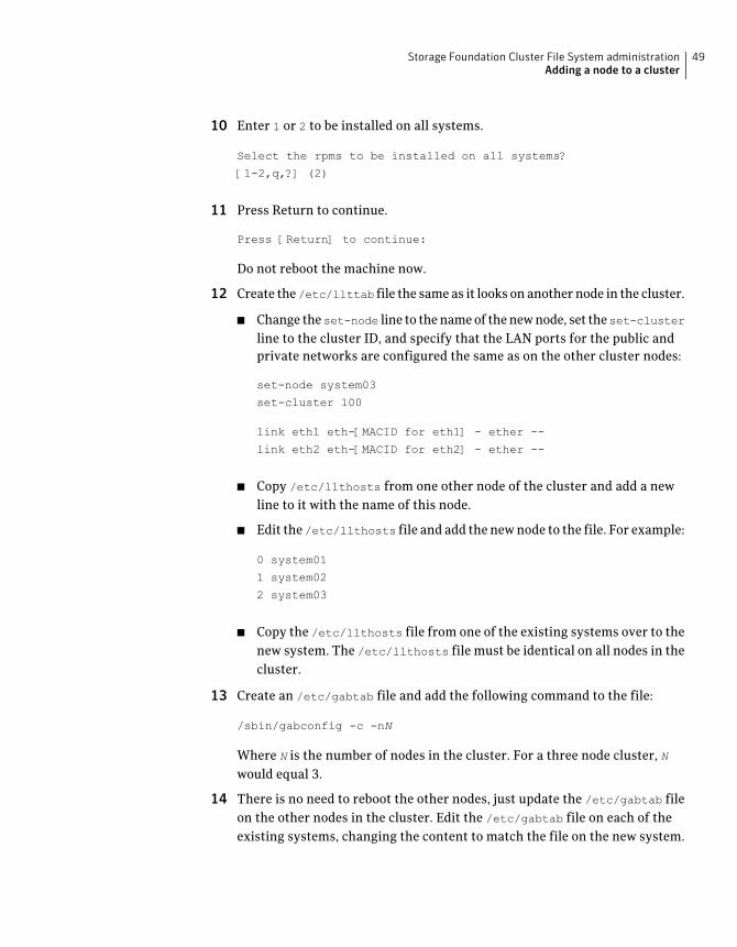
10 Enter 1 or 2 to be installed on all systems.
Select the rpms to be installed on all systems?
[1-2,q,?] (2)
11 Press Return to continue.
Press [Return] to continue:
Do not reboot the machine now.
12 Create the /etc/llttab file the same as it looks on another node in the cluster.
■ Change theset-node line to the name of the new node, set theset-clusterline to the cluster ID, and specify that the LAN ports for the public andprivate networks are configured the same as on the other cluster nodes:
set-node system03
set-cluster 100
link eth1 eth-[MACID for eth1] - ether --
link eth2 eth-[MACID for eth2] - ether --
■ Copy /etc/llthosts from one other node of the cluster and add a newline to it with the name of this node.
■ Edit the /etc/llthosts file and add the new node to the file. For example:
0 system01
1 system02
2 system03
■ Copy the /etc/llthosts file from one of the existing systems over to thenew system. The /etc/llthosts file must be identical on all nodes in thecluster.
13 Create an /etc/gabtab file and add the following command to the file:
/sbin/gabconfig -c -nN
Where N is the number of nodes in the cluster. For a three node cluster, Nwould equal 3.
14 There is no need to reboot the other nodes, just update the /etc/gabtab fileon the other nodes in the cluster. Edit the /etc/gabtab file on each of theexisting systems, changing the content to match the file on the new system.
49Storage Foundation Cluster File System administrationAdding a node to a cluster
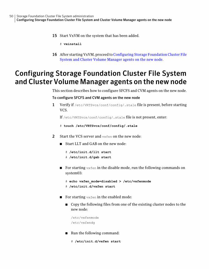
15 Start VxVM on the system that has been added.
# vxinstall
16 After starting VxVM, proceed to Configuring Storage Foundation Cluster FileSystem and Cluster Volume Manager agents on the new node.
Configuring Storage Foundation Cluster File SystemandCluster VolumeManager agents on the newnode
This section describes how to configure SFCFS and CVM agents on the new node.
To configure SFCFS and CVM agents on the new node
1 Verify if /etc/VRTSvcs/conf/config/.stale file is present, before startingVCS.
If /etc/VRTSvcs/conf/config/.stale file is not present, enter:
# touch /etc/VRTSvcs/conf/config/.stale
2 Start the VCS server and vxfen on the new node:
■ Start LLT and GAB on the new node:
# /etc/init.d/llt start
# /etc/init.d/gab start
■ For starting vxfen in the disable mode, run the following commands onsystem03:
# echo vxfen_mode=disabled > /etc/vxfenmode
# /etc/init.d/vxfen start
■ For starting vxfen in the enabled mode:
■ Copy the following files from one of the existing cluster nodes to thenew node:
/etc/vxfenmode
/etc/vxfendg
■ Run the following command:
# /etc/init.d/vxfen start
Storage Foundation Cluster File System administrationConfiguring Storage Foundation Cluster File System and Cluster Volume Manager agents on the new node
50
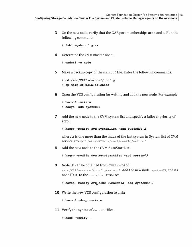
3 On the new node, verify that the GAB port memberships are a and b. Run thefollowing command:
# /sbin/gabconfig -a
4 Determine the CVM master node:
# vxdctl -c mode
5 Make a backup copy of the main.cf file. Enter the following commands:
# cd /etc/VRTSvcs/conf/config
# cp main.cf main.cf.2node
6 Open the VCS configuration for writing and add the new node. For example:
# haconf -makerw
# hasys -add system03
7 Add the new node to the CVM system list and specify a failover priority ofzero:
# hagrp -modify cvm SystemList -add system03 X
where X is one more than the index of the last system in System list of CVMservice group in /etc/VRTSvcs/conf/config/main.cf.
8 Add the new node to the CVM AutoStartList:
# hagrp -modify cvm AutoStartList -add system03
9 Node ID can be obtained from CVMNodeId of/etc/VRTSvcs/conf/config/main.cf. Add the new node, system03, and itsnode ID, #, to the cvm_clust resource:
# hares -modify cvm_clus CVMNodeId -add system03 2
10 Write the new VCS configuration to disk:
# haconf -dump -makero
11 Verify the syntax of main.cf file:
# hacf -verify .
51Storage Foundation Cluster File System administrationConfiguring Storage Foundation Cluster File System and Cluster Volume Manager agents on the new node
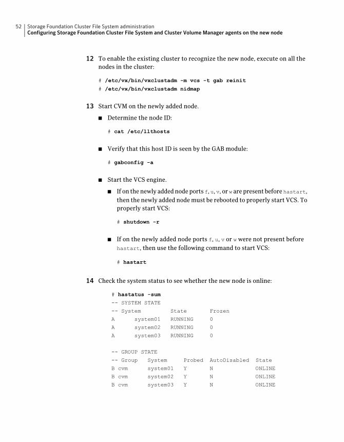
12 To enable the existing cluster to recognize the new node, execute on all thenodes in the cluster:
# /etc/vx/bin/vxclustadm -m vcs -t gab reinit
# /etc/vx/bin/vxclustadm nidmap
13 Start CVM on the newly added node.
■ Determine the node ID:
# cat /etc/llthosts
■ Verify that this host ID is seen by the GAB module:
# gabconfig -a
■ Start the VCS engine.
■ If on the newly added node ports f, u, v, or w are present before hastart,then the newly added node must be rebooted to properly start VCS. Toproperly start VCS:
# shutdown -r
■ If on the newly added node ports f, u, v or w were not present beforehastart, then use the following command to start VCS:
# hastart
14 Check the system status to see whether the new node is online:
# hastatus -sum
-- SYSTEM STATE
-- System State Frozen
A system01 RUNNING 0
A system02 RUNNING 0
A system03 RUNNING 0
-- GROUP STATE
-- Group System Probed AutoDisabled State
B cvm system01 Y N ONLINE
B cvm system02 Y N ONLINE
B cvm system03 Y N ONLINE
Storage Foundation Cluster File System administrationConfiguring Storage Foundation Cluster File System and Cluster Volume Manager agents on the new node
52
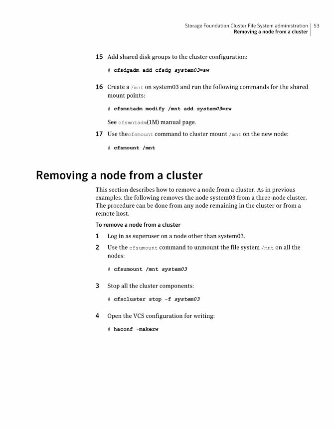
15 Add shared disk groups to the cluster configuration:
# cfsdgadm add cfsdg system03=sw
16 Create a /mnt on system03 and run the following commands for the sharedmount points:
# cfsmntadm modify /mnt add system03=rw
See cfsmntadm(1M) manual page.
17 Use thecfsmount command to cluster mount /mnt on the new node:
# cfsmount /mnt
Removing a node from a clusterThis section describes how to remove a node from a cluster. As in previousexamples, the following removes the node system03 from a three-node cluster.The procedure can be done from any node remaining in the cluster or from aremote host.
To remove a node from a cluster
1 Log in as superuser on a node other than system03.
2 Use the cfsumount command to unmount the file system /mnt on all thenodes:
# cfsumount /mnt system03
3 Stop all the cluster components:
# cfscluster stop -f system03
4 Open the VCS configuration for writing:
# haconf -makerw
53Storage Foundation Cluster File System administrationRemoving a node from a cluster
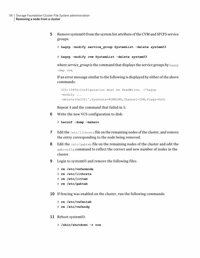
5 Remove system03 from the system list attribute of the CVM and SFCFS servicegroups:
# hagrp -modify service_group SystemList -delete system03
# hagrp -modify cvm SystemList -delete system03
where service_group is the command that displays the service groups by hagrp-dep cvm.
If an error message similar to the following is displayed by either of the abovecommands:
VCS:10456:Configuration must be ReadWrite. ('hagrp
-modify ...
-delete(0x10f)',Sysstate=RUNNING,Channel=IPM,Flags=0x0)
Repeat 4 and the command that failed in 5.
6 Write the new VCS configuration to disk:
# haconf -dump -makero
7 Edit the /etc/llthosts file on the remaining nodes of the cluster, and removethe entry corresponding to the node being removed.
8 Edit the /etc/gabtab file on the remaining nodes of the cluster and edit thegabconfig command to reflect the correct and new number of nodes in thecluster.
9 Login to system03 and remove the following files:
# rm /etc/vxfenmode
# rm /etc/llthosts
# rm /etc/llttab
# rm /etc/gabtab
10 If fencing was enabled on the cluster, run the following commands:
# rm /etc/vxfentab
# rm /etc/vxfendg
11 Reboot system03:
# /sbin/shutdown -r now
Storage Foundation Cluster File System administrationRemoving a node from a cluster
54
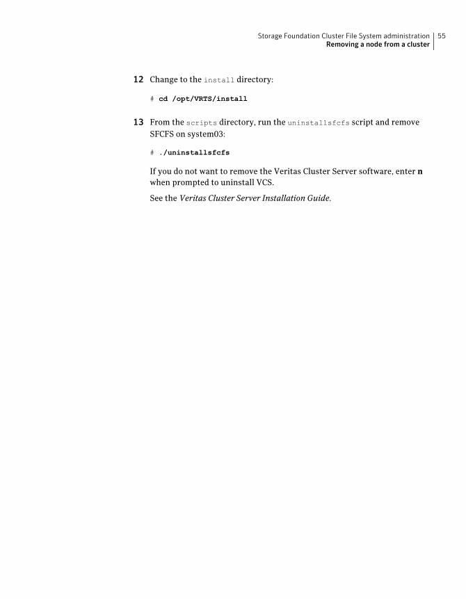
12 Change to the install directory:
# cd /opt/VRTS/install
13 From the scripts directory, run the uninstallsfcfs script and removeSFCFS on system03:
# ./uninstallsfcfs
If you do not want to remove the Veritas Cluster Server software, enter nwhen prompted to uninstall VCS.
See the Veritas Cluster Server Installation Guide.
55Storage Foundation Cluster File System administrationRemoving a node from a cluster

Storage Foundation Cluster File System administrationRemoving a node from a cluster
56
Storage Foundation ClusterFile System for Oracle RAC
This chapter includes the following topics:
■ Storage Foundation Cluster File System for Oracle RAC
Storage Foundation Cluster File System for OracleRAC
Maintenance Pack 3 for Veritas Storage Foundation Cluster File System (SFCFS)5.0 includes support for Oracle RAC.
SFCFS for Oracle RAC supports dynamic multi-pathing (DMP), Oracle Disk Manager(ODM) and Group Membership Services.
SFCFS for Oracle RAC does not support the integration of Veritas Cluster Server(VCS) with the Oracle Clusterware APIs.
In addition, although I/O Fencing may be enabled, it is not supported for use withSFCFS for Oracle RAC. If I/O Fencing is configured, the functionality is notavailable.
Oracle Cluster Registry (OCR) and Vote-disk are not supported on Cluster FileSystem (CFS). Symantec recommends keeping OCR and Vote-disk on volumescreated by the Cluster Volume Manager (CVM).
CRS_HOME is not supported on Cluster File System (CFS).
About Storage Foundation Cluster File System for Oracle RACSFCFS for Oracle RAC is a storage management and clustering solution.
SFCFS for Oracle RAC provides the following features:
4Chapter
■ Enhanced scalability and availability with access to multiple RAC instancesper database in a cluster.
■ Back up and recovery of databases using volume-level and file system-levelsnapshot technologies. SFCFS for Oracle RAC enables full volume-levelsnapshots for off-host processing that reduce load on production systems. Thefile system-level snapshots that involve efficient backup and rollback processes.
■ Sharing of all types of files, in addition to Oracle database files, across nodes.
■ Increased availability and performance with dynamic multi-pathing (DMP),which provides wide storage array support for protection from failures andperformance bottlenecks in the HBAs and SAN switches.
■ Optimized I/O performance and memory footprints through storage mappingtechnologies, such as ODM, and tunable attributes.
How SFCFS for Oracle RAC works (high-level perspective)Real Application Clusters (RAC) is a parallel database environment that takesadvantage of the processing power of multiple computers. The Oracle databaseis the physical data stored in tablespaces on disk. The Oracle instance is a set ofprocesses and shared memory that provide access to the physical database.Specifically, the instance involves server processes acting on behalf of clients toread data into shared memory and make modifications to it, and backgroundprocesses to write changed data to disk.
In traditional environments, only one instance accesses a database at a specifictime. SFCFS for Oracle RAC enables all nodes to concurrently run Oracle instancesand execute transactions against the same database. This software coordinatesaccess to the shared data for each node to provide consistency and integrity.
Each node adds its processing power to the cluster as a whole and can increaseoverall throughput or performance.
At a conceptual level, SFCFS for Oracle RAC is a cluster that manages applications(instances), networking, and storage components using resources that arecontained in service groups.
SFCFS for Oracle RAC clusters have many of the same properties as Veritas ClusterServer (VCS) clusters, such as the following:
■ Each node runs its own operating system.
■ A cluster interconnect enables cluster communications.
■ A public network connects each node to a LAN for client access.
■ Shared storage is accessible by each node that needs to run the application.
Storage Foundation Cluster File System for Oracle RACStorage Foundation Cluster File System for Oracle RAC
58
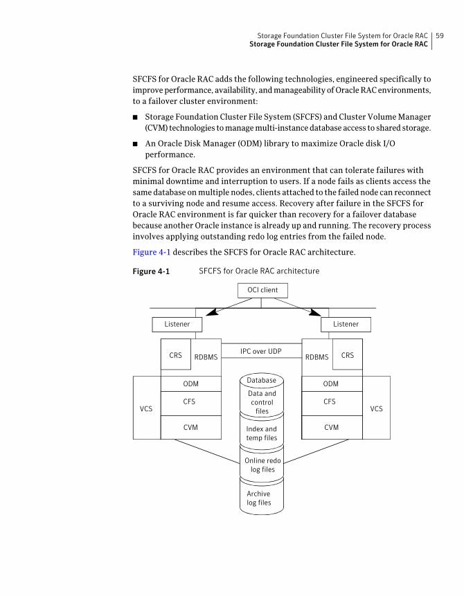
SFCFS for Oracle RAC adds the following technologies, engineered specifically toimprove performance, availability, and manageability of Oracle RAC environments,to a failover cluster environment:
■ Storage Foundation Cluster File System (SFCFS) and Cluster Volume Manager(CVM) technologies to manage multi-instance database access to shared storage.
■ An Oracle Disk Manager (ODM) library to maximize Oracle disk I/Operformance.
SFCFS for Oracle RAC provides an environment that can tolerate failures withminimal downtime and interruption to users. If a node fails as clients access thesame database on multiple nodes, clients attached to the failed node can reconnectto a surviving node and resume access. Recovery after failure in the SFCFS forOracle RAC environment is far quicker than recovery for a failover databasebecause another Oracle instance is already up and running. The recovery processinvolves applying outstanding redo log entries from the failed node.
Figure 4-1 describes the SFCFS for Oracle RAC architecture.
Figure 4-1 SFCFS for Oracle RAC architecture
`
RDBMS
ODM
CFS
CVM
VCS
RDBMSCRS
ODM
CFS
CVM
VCS
ListenerListener
Database
Data andcontrol
files
Index andtemp files
Online redolog files
Archivelog files
OCI client
CRSIPC over UDP
59Storage Foundation Cluster File System for Oracle RACStorage Foundation Cluster File System for Oracle RAC
Component products and processes of SFCFS for Oracle RACTo understand how Storage Foundation Cluster File System for Oracle RAC (SFCFSfor Oracle RAC) manages database instances running in parallel on multiple nodes,review the architecture and communication mechanisms that provide theinfrastructure for Oracle RAC.
General highlights of the component products include the following.
Enables simultaneous access to shared volumes based ontechnology from Veritas Volume Manager (VxVM).
Cluster Volume Manager (CVM)
Enables simultaneous access to shared file systems basedon technology from Veritas File System (VxFS).
Storage Foundation Cluster FileSystem (SFCFS)
Provides the interface with the Oracle Disk Manager(ODM) API.
Database Accelerator
Provides cluster membership, a messaging layer,management of CVM and CFS service groups andresources.
Cluster Server (VCS)
Communication infrastructureTo understand the communication infrastructure, it is necessary to review thedata flow and communications requirements.
Data flowThe CVM, CFS, ODM, and Oracle RAC elements reflect the overall data flow, ordata stack, from an instance running on a server to the shared storage. The variousOracle processes that compose an instance (such as DB Writers, Checkpoint,Archiver, Log Writer, and Server) read and write data to the storage through theI/O stack. Oracle communicates through the ODM interface to CFS, which in turnaccesses the storage through CVM.
Figure 4-2 describes the data flow in SFCFS for Oracle RAC.
Storage Foundation Cluster File System for Oracle RACStorage Foundation Cluster File System for Oracle RAC
60
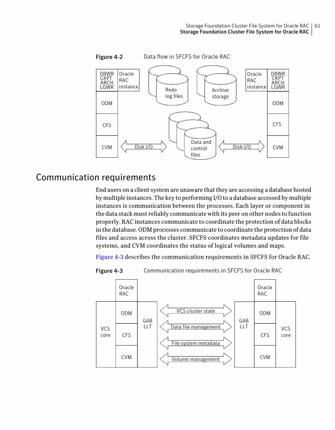
Figure 4-2 Data flow in SFCFS for Oracle RAC
RedoRedolog files
Archivestorage
Data andcontrolfiles
LGWR
ODM
CFS
CVM
OracleRACinstance
ARCHCKPTDBWR
LGWR
ODM
CFS
CVM
OracleRACinstance
ARCHCKPTDBWR
Disk I/ODisk I/O
Communication requirementsEnd users on a client system are unaware that they are accessing a database hostedby multiple instances. The key to performing I/O to a database accessed by multipleinstances is communication between the processes. Each layer or component inthe data stack must reliably communicate with its peer on other nodes to functionproperly. RAC instances communicate to coordinate the protection of data blocksin the database. ODM processes communicate to coordinate the protection of datafiles and access across the cluster. SFCFS coordinates metadata updates for filesystems, and CVM coordinates the status of logical volumes and maps.
Figure 4-3 describes the communication requirements in SFCFS for Oracle RAC.
Figure 4-3 Communication requirements in SFCFS for Oracle RAC
VCScore
OracleRAC
ODM
CFS
CVM
GABLLTVCS
core
OracleRAC
ODM
CFS
CVM
GABLLT Data file management
File system metadata
VCS cluster state
Volume management
61Storage Foundation Cluster File System for Oracle RACStorage Foundation Cluster File System for Oracle RAC
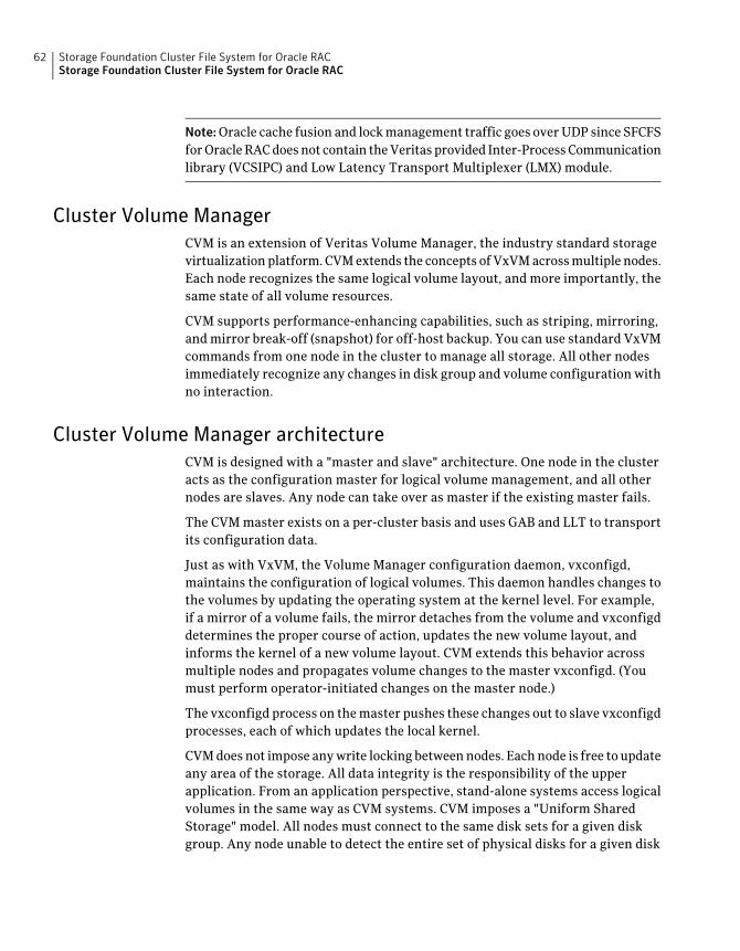
Note:Oracle cache fusion and lock management traffic goes over UDP since SFCFSfor Oracle RAC does not contain the Veritas provided Inter-Process Communicationlibrary (VCSIPC) and Low Latency Transport Multiplexer (LMX) module.
Cluster Volume ManagerCVM is an extension of Veritas Volume Manager, the industry standard storagevirtualization platform. CVM extends the concepts of VxVM across multiple nodes.Each node recognizes the same logical volume layout, and more importantly, thesame state of all volume resources.
CVM supports performance-enhancing capabilities, such as striping, mirroring,and mirror break-off (snapshot) for off-host backup. You can use standard VxVMcommands from one node in the cluster to manage all storage. All other nodesimmediately recognize any changes in disk group and volume configuration withno interaction.
Cluster Volume Manager architectureCVM is designed with a "master and slave" architecture. One node in the clusteracts as the configuration master for logical volume management, and all othernodes are slaves. Any node can take over as master if the existing master fails.
The CVM master exists on a per-cluster basis and uses GAB and LLT to transportits configuration data.
Just as with VxVM, the Volume Manager configuration daemon, vxconfigd,maintains the configuration of logical volumes. This daemon handles changes tothe volumes by updating the operating system at the kernel level. For example,if a mirror of a volume fails, the mirror detaches from the volume and vxconfigddetermines the proper course of action, updates the new volume layout, andinforms the kernel of a new volume layout. CVM extends this behavior acrossmultiple nodes and propagates volume changes to the master vxconfigd. (Youmust perform operator-initiated changes on the master node.)
The vxconfigd process on the master pushes these changes out to slave vxconfigdprocesses, each of which updates the local kernel.
CVM does not impose any write locking between nodes. Each node is free to updateany area of the storage. All data integrity is the responsibility of the upperapplication. From an application perspective, stand-alone systems access logicalvolumes in the same way as CVM systems. CVM imposes a "Uniform SharedStorage" model. All nodes must connect to the same disk sets for a given diskgroup. Any node unable to detect the entire set of physical disks for a given disk
Storage Foundation Cluster File System for Oracle RACStorage Foundation Cluster File System for Oracle RAC
62
group cannot import the group. If a node loses contact with a specific disk, CVMexcludes the node from participating in the use of that disk.
Storage Foundation Cluster File SystemCFS enables you to simultaneously mount the same file system on multiple nodesand is an extension of the industry-standard Veritas File System. Unlike someother file systems that send data through another node to the storage, CFS is atrue SAN file system. All data traffic takes place over the storage area network(SAN), and only the metadata traverses the cluster interconnect.
In addition to using the SAN fabric for reading and writing data, CFS offers storagecheckpoints and rollback for backup and recovery.
Storage Foundation Cluster File System architectureSFCFS for Oracle RAC uses CFS to manage a file system in a large databaseenvironment. Since CFS is an extension of VxFS, it operates in a similar fashionand caches metadata and data in memory (typically called buffer cache or vnodecache). CFS uses a distributed locking mechanism called Global Lock Manager(GLM) to ensure all nodes have a consistent view of the file system. GLM providesmetadata and cache coherency across multiple nodes by coordinating access tofile system metadata, such as inodes and free lists. The role of GLM is set on aper-file system basis to enable load balancing.
CFS involves a primary/secondary architecture. Though any node can initiate anoperation to create, delete, or resize data, the GLM master node carries out theactual operation. After creating a file, the GLM master node grants locks for datacoherency across nodes. For example, if a node tries to modify a row of a block ina file, it must obtain an exclusive lock to ensure other nodes that may have thesame file cached have this cached copy invalidated.
SFCFS for Oracle RAC configurations minimize the use of GLM locking. OracleRAC accesses the file system through the ODM interface and handles its ownlocking; only Oracle (and not GLM) buffers data and coordinates write operationsto files.
A single point of locking and buffering ensures maximum performance. GLMlocking is only involved when metadata for a file changes, such as during createand resize operations.
63Storage Foundation Cluster File System for Oracle RACStorage Foundation Cluster File System for Oracle RAC
Oracle Disk ManagerSFCFS for Oracle RAC requires Oracle Disk Manager (ODM), a standard APIpublished by Oracle for support of database I/O. SFCFS for Oracle RAC providesa library for Oracle to use as its I/O library.
Oracle Disk Manager architectureWhen the ODM library is linked, Oracle is able to bypass all caching and locks atthe file system layer and to communicate directly with raw volumes.
The SFCFS for Oracle RAC implementation of ODM generates performanceequivalent to performance with raw devices while the storage uses easy-to-managefile systems.
All ODM features can operate in a cluster environment. Nodes communicate witheach other before performing any operation that could potentially affect anothernode. For example, before creating a new data file with a specific name, ODMchecks with other nodes to see if the file name is already in use.
Oracle Disk Manager performance enhancementsThe following describes ODM performance enhancements.
ODM enables the following performance benefits that are provided by the OracleDisk Manager:
■ Locking for data integrity.
■ Few system calls and context switches.
■ Increased I/O parallelism.
■ Efficient file creation and disk allocation.
Databases using file systems typically incur the following additional overhead:
■ Extra CPU and memory usage to read data from underlying disks to the filesystem cache. This scenario requires copying data from the file system cacheto the Oracle cache.
■ File locking that allows for only a single writer at a time. Allowing Oracle toperform locking allows for finer granularity of locking at the row level.
■ File systems generally go through a standard Sync I/O library when performingI/O. Oracle can make use of Kernel Async I/O libraries (KAIO) with raw devicesto improve performance.
Storage Foundation Cluster File System for Oracle RACStorage Foundation Cluster File System for Oracle RAC
64
Veritas Cluster Server functionality for SFCFS for Oracle RACThe following VCS functionality is provided for SFCFS for Oracle RAC.
Veritas Cluster Server provides the following functionality for SFCFS for OracleRAC:
■ Management of cluster node membership, including the monitoring of nodehealth by using heart-beat technology.
■ A messaging layer between cluster nodes.
■ Management of CVM and SFCFS service groups and resources and theirinterdependencies.
Veritas Cluster Server architectureThe High Availability Daemon (HAD) is the main VCS daemon running on eachnode. HAD tracks changes in the cluster configuration and monitors resourcestatus by communicating with GAB and LLT. HAD manages all application servicesusing agents, which are installed programs to manage resources (specific hardwareor software entities).
The VCS architecture is modular for extensibility and efficiency. HAD does notneed to know how to start up Oracle or any other application under VCS control.
Instead, you can add agents to manage different resources with no effect on theengine (HAD). Agents only communicate with HAD on the local node, and HADcommunicates status with HAD processes on other nodes. Because agents do notneed to communicate across systems, VCS is able to minimize traffic on the clusterinterconnect.
SFCFS for Oracle RAC provides specific agents for VCS to manage CVM and SFCFS.
Cluster configuration filesVCS uses the following configuration files in a default configuration.
Defines the entire cluster, including the cluster name, systems in thecluster, definitions of service groups, resources, and in addition toservice group and resource dependencies.
main.cf
Defines the resource typestypes.cf
Additional files similar to types.cf file may be present if you add agents.
65Storage Foundation Cluster File System for Oracle RACStorage Foundation Cluster File System for Oracle RAC
Installing and configuring SFCFS for Oracle RACYou can install SFCFS for Oracle RAC on clusters of up to 16 nodes. You can alsoupgrade an existing SFCFS cluster to SFCFS for Oracle RAC.
The Veritas product installer or the installsfcfsrac scripts may be used toperform a fresh installation of SFCFS for Oracle RAC.
The following packages are installed on each cluster node:
■ Veritas Cluster Server (VCS)
■ Veritas Volume Manager (VxVM)
■ Veritas File System (VxFS)
■ Oracle Disk Manager (ODM)
To perform system checks and configure SFCFS for Oracle RAC, you can use theVeritas product installer or the -configure option of the installsfcfsrac
script. You can configure the following components of SFCFS for Oracle RAC:
■ VCS
■ CVM (Veritas Volume Manager enabled for clusters)
■ CFS (Veritas File System enabled for clusters)
The installer and installsfcfsrac scripts also start the SFCFS for Oracle RACprocesses.
See the Veritas Storage Foundation Installation Guide.
Recommendations before installing Oracle softwareAfter installing and configuring SFCFS for Oracle RAC and before installing Oraclesoftware, read the following recommendations.
About the location of ORACLE_HOME
ORACLE_HOME is the location where the Oracle Database binaries are installed.Before installing Oracle binaries on ORACLE_HOME locally on each node or on acluster file system on shared storage, read and comply with the followinginformation:
■ Local installations provide a comfort level using traditional installationmethods and the possibility of improved protection against a single point offailure.
■ SFCFS installations provide a single Oracle installation to manage, regardlessof the number of nodes. This scenario offers a necessary reduction in storagerequirements and easy addition of nodes.
Storage Foundation Cluster File System for Oracle RACStorage Foundation Cluster File System for Oracle RAC
66
Select the location based on your high availability (HA) requirements. Symantecand Oracle recommend using local installations.
About the location of CRS_HOME
CRS_HOME is the location where Oracle Clusterware binaries are installed. CRS_HOMEis not supported on Cluster File System (CFS).
Creating the Oracle user and groupOn each system, create a local group and local user for Oracle. Be sure to assignthe same group ID, user ID, and home directory for the user on each system. Thefollowing example creates the group oinstall and the user oracle.
To create the operating system Oracle user and group on each system
1 Create the oinstall group on each system:
# groupadd -g 1000 oinstall
# groupadd -g 1001 dba
2 Create the oracle user and the oracle ID on each system:
# useradd -g oinstall -u user_id -G dba -d /home/oracle oracle
3 Enable rsh and key-based authentication ssh for the oracle user on all nodes.
See the Oracle product documentation for more information on creating theOracle user and group.
Creating CRS_HOMEThe following procedure creates CRS_HOME.
To create CRS_HOME on each system
1 Log in as root user on one system.
# su - root
2 On one node, create a disk group:
# vxdg init crsdg sdc
67Storage Foundation Cluster File System for Oracle RACStorage Foundation Cluster File System for Oracle RAC
3 Create the volume in the group for CRS_HOME:
# vxassist -g crsdg make crsvol 500M
Refer to the Oracle product documentation for exact size requirements forCRS_HOME.
4 Create a VxFS file system on which to install CRS:
# mkfs -t vxfs /dev/vx/rdsk/crsdg/crsvol
5 Create the mount point for CRS_HOME:
# mkdir /oracle/crs
6 Mount the file system, using the device file for the block device:
# mount -t vxfs /dev/vx/dsk/crsdg/crsvol /oracle/crs
7 Edit the /etc/fstab file and list the new file system:
/dev/vx/dsk/crsdg/crsvol /oracle/crs vxfs defaults 1 1
8 Export the CRS_HOME directory as /oracle/crs for the oracle user.
9 Assign ownership of the directory to oracle and the group oinstall:
# chown -R oracle:oinstall /oracle/crs
# chmod -R 755 /oracle/crs
10 On each cluster node, repeat step 1 through step 9.
Creating ORACLE_HOMEThe following procedure creates ORACLE_HOME.
Storage Foundation Cluster File System for Oracle RACStorage Foundation Cluster File System for Oracle RAC
68
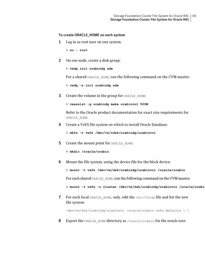
To create ORACLE_HOME on each system
1 Log in as root user on one system.
# su - root
2 On one node, create a disk group:
# vxdg init orabindg sde
For a shared ORACLE_HOME, run the following command on the CVM master:
# vxdg -s init orabindg sde
3 Create the volume in the group for ORACLE_HOME:
# vxassist -g orabindg make orabinvol 500M
Refer to the Oracle product documentation for exact size requirements forORACLE_HOME.
4 Create a VxFS file system on which to install Oracle Database:
# mkfs -t vxfs /dev/vx/rdsk/orabindg/orabinvol
5 Create the mount point for ORACLE_HOME:
# mkdir /oracle/orabin
6 Mount the file system, using the device file for the block device:
# mount -t vxfs /dev/vx/dsk/orabindg/orabinvol /oracle/orabin
For each sharedORACLE_HOME, run the following command on the CVM master:
# mount -t vxfs -o cluster /dev/vx/dsk/orabindg/orabinvol /oracle/orabin
7 For each local ORACLE_HOME, only, edit the /etc/fstab file and list the newfile system:
/dev/vx/dsk/orabindg/orabinvol /oracle/orabin vxfs defaults 1 1
8 Export the ORACLE_HOME directory as /oracle/orabin for the oracle user.
69Storage Foundation Cluster File System for Oracle RACStorage Foundation Cluster File System for Oracle RAC
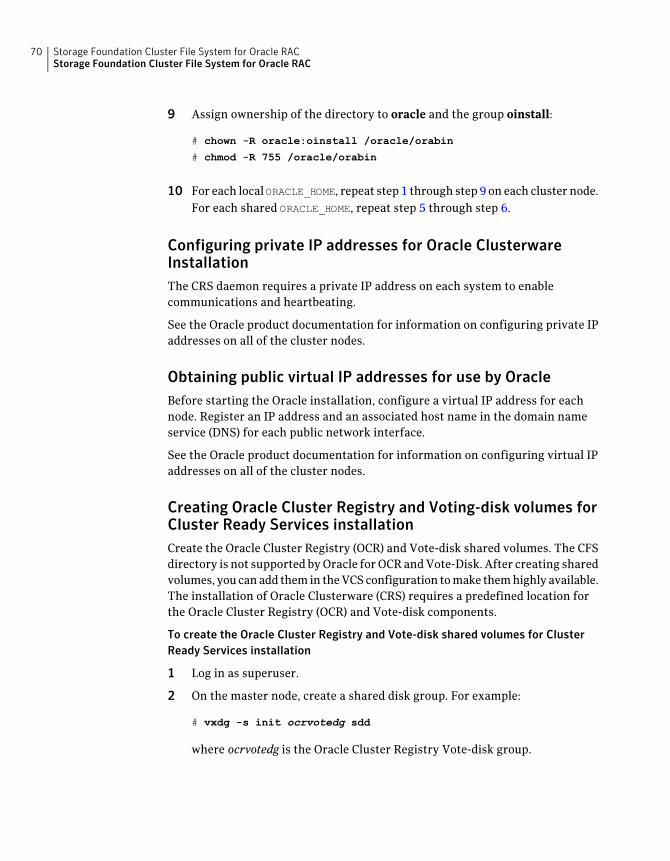
9 Assign ownership of the directory to oracle and the group oinstall:
# chown -R oracle:oinstall /oracle/orabin
# chmod -R 755 /oracle/orabin
10 For each local ORACLE_HOME, repeat step 1 through step 9 on each cluster node.For each shared ORACLE_HOME, repeat step 5 through step 6.
Configuring private IP addresses for Oracle ClusterwareInstallationThe CRS daemon requires a private IP address on each system to enablecommunications and heartbeating.
See the Oracle product documentation for information on configuring private IPaddresses on all of the cluster nodes.
Obtaining public virtual IP addresses for use by OracleBefore starting the Oracle installation, configure a virtual IP address for eachnode. Register an IP address and an associated host name in the domain nameservice (DNS) for each public network interface.
See the Oracle product documentation for information on configuring virtual IPaddresses on all of the cluster nodes.
Creating Oracle Cluster Registry and Voting-disk volumes forCluster Ready Services installationCreate the Oracle Cluster Registry (OCR) and Vote-disk shared volumes. The CFSdirectory is not supported by Oracle for OCR and Vote-Disk. After creating sharedvolumes, you can add them in the VCS configuration to make them highly available.The installation of Oracle Clusterware (CRS) requires a predefined location forthe Oracle Cluster Registry (OCR) and Vote-disk components.
To create the Oracle Cluster Registry and Vote-disk shared volumes for ClusterReady Services installation
1 Log in as superuser.
2 On the master node, create a shared disk group. For example:
# vxdg -s init ocrvotedg sdd
where ocrvotedg is the Oracle Cluster Registry Vote-disk group.
Storage Foundation Cluster File System for Oracle RACStorage Foundation Cluster File System for Oracle RAC
70
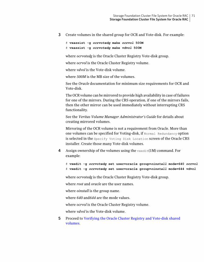
3 Create volumes in the shared group for OCR and Vote-disk. For example:
# vxassist -g ocrvotedg make ocrvol 500M
# vxassist -g ocrvotedg make vdvol 500M
where ocrvotedg is the Oracle Cluster Registry Vote-disk group.
where ocrvol is the Oracle Cluster Registry volume.
where vdvol is the Vote-disk volume.
where 500M is the MB size of the volumes.
See the Oracle documentation for minimum size requirements for OCR andVote-disk.
The OCR volume can be mirrored to provide high availability in case of failuresfor one of the mirrors. During the CRS operation, if one of the mirrors fails,then the other mirror can be used immediately without interrupting CRSfunctionality.
See the Veritas VolumeManager Administrator's Guide for details aboutcreating mirrored volumes.
Mirroring of the OCR volume is not a requirement from Oracle. More thanone volumes can be specified for Voting-disk, if Normal Redundancy optionis selected in the Specify Voting Disk Location screen of the Oracle CRSinstaller. Create those many Vote-disk volumes.
4 Assign ownership of the volumes using the vxedit(1M) command. Forexample:
# vxedit -g ocrvotedg set user=oracle group=oinstall mode=640 ocrvol
# vxedit -g ocrvotedg set user=oracle group=oinstall mode=644 vdvol
where ocrvotedg is the Oracle Cluster Registry Vote-disk group.
where root and oracle are the user names.
where oinstall is the group name.
where 640 and644 are the mode values.
where ocrvol is the Oracle Cluster Registry volume.
where vdvol is the Vote-disk volume.
5 Proceed to Verifying the Oracle Cluster Registry and Vote-disk sharedvolumes.
71Storage Foundation Cluster File System for Oracle RACStorage Foundation Cluster File System for Oracle RAC
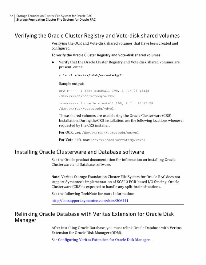
Verifying the Oracle Cluster Registry and Vote-disk shared volumesVerifying the OCR and Vote-disk shared volumes that have been created andconfigured.
To verify the Oracle Cluster Registry and Vote-disk shared volumes
◆ Verify that the Oracle Cluster Registry and Vote-disk shared volumes arepresent, enter:
# ls -l /dev/vx/rdsk/ocrvotedg/*
Sample output:
crw-r----- 1 root oinstall 199, 3 Jun 26 15:58
/dev/vx/rdsk/ocrvotedg/ocrvol
crw-r--r-- 1 oracle oinstall 199, 4 Jun 26 15:58
/dev/vx/rdsk/ocrvotedg/vdvol
These shared volumes are used during the Oracle Clusterware (CRS)Installation. During the CRS installation, use the following locations wheneverrequested by the CRS installer.
For OCR, use: /dev/vx/rdsk/ocrvotedg/ocrvol
For Vote-disk, use: /dev/vx/rdsk/ocrvotedg/vdvol
Installing Oracle Clusterware and Database softwareSee the Oracle product documentation for information on installing OracleClusterware and Database software.
Note: Veritas Storage Foundation Cluster File System for Oracle RAC does notsupport Symantec's implementation of SCSI-3 PGR-based I/O fencing. OracleClusterware (CRS) is expected to handle any split-brain situations.
See the following TechNote for more information:
http://entsupport.symantec.com/docs/306411
Relinking Oracle Database with Veritas Extension for Oracle DiskManager
After installing Oracle Database, you must relink Oracle Database with VeritasExtension for Oracle Disk Manager (ODM).
See Configuring Veritas Extension for Oracle Disk Manager.
Storage Foundation Cluster File System for Oracle RACStorage Foundation Cluster File System for Oracle RAC
72
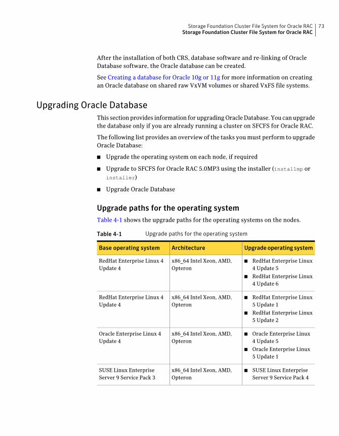
After the installation of both CRS, database software and re-linking of OracleDatabase software, the Oracle database can be created.
See Creating a database for Oracle 10g or 11g for more information on creatingan Oracle database on shared raw VxVM volumes or shared VxFS file systems.
Upgrading Oracle DatabaseThis section provides information for upgrading Oracle Database. You can upgradethe database only if you are already running a cluster on SFCFS for Oracle RAC.
The following list provides an overview of the tasks you must perform to upgradeOracle Database:
■ Upgrade the operating system on each node, if required
■ Upgrade to SFCFS for Oracle RAC 5.0MP3 using the installer (installmp orinstaller)
■ Upgrade Oracle Database
Upgrade paths for the operating systemTable 4-1 shows the upgrade paths for the operating systems on the nodes.
Table 4-1 Upgrade paths for the operating system
Upgradeoperating systemArchitectureBase operating system
■ RedHat Enterprise Linux4 Update 5
■ RedHat Enterprise Linux4 Update 6
x86_64 Intel Xeon, AMD,Opteron
RedHat Enterprise Linux 4Update 4
■ RedHat Enterprise Linux5 Update 1
■ RedHat Enterprise Linux5 Update 2
x86_64 Intel Xeon, AMD,Opteron
RedHat Enterprise Linux 4Update 4
■ Oracle Enterprise Linux4 Update 5
■ Oracle Enterprise Linux5 Update 1
x86_64 Intel Xeon, AMD,Opteron
Oracle Enterprise Linux 4Update 4
■ SUSE Linux EnterpriseServer 9 Service Pack 4
x86_64 Intel Xeon, AMD,Opteron
SUSE Linux EnterpriseServer 9 Service Pack 3
73Storage Foundation Cluster File System for Oracle RACStorage Foundation Cluster File System for Oracle RAC
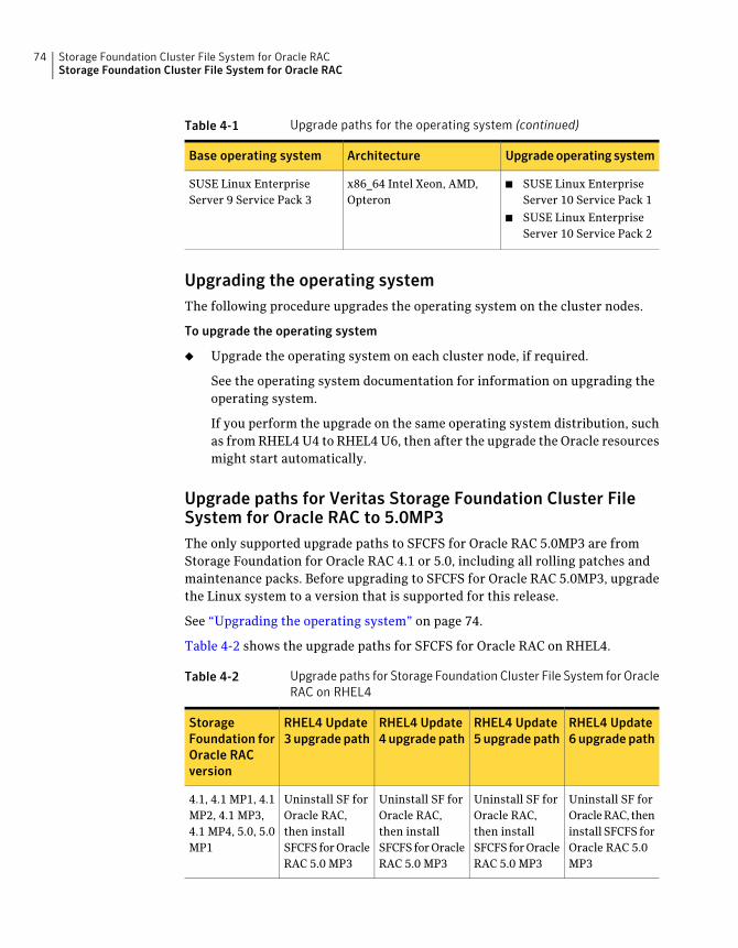
Table 4-1 Upgrade paths for the operating system (continued)
Upgradeoperating systemArchitectureBase operating system
■ SUSE Linux EnterpriseServer 10 Service Pack 1
■ SUSE Linux EnterpriseServer 10 Service Pack 2
x86_64 Intel Xeon, AMD,Opteron
SUSE Linux EnterpriseServer 9 Service Pack 3
Upgrading the operating systemThe following procedure upgrades the operating system on the cluster nodes.
To upgrade the operating system
◆ Upgrade the operating system on each cluster node, if required.
See the operating system documentation for information on upgrading theoperating system.
If you perform the upgrade on the same operating system distribution, suchas from RHEL4 U4 to RHEL4 U6, then after the upgrade the Oracle resourcesmight start automatically.
Upgrade paths for Veritas Storage Foundation Cluster FileSystem for Oracle RAC to 5.0MP3The only supported upgrade paths to SFCFS for Oracle RAC 5.0MP3 are fromStorage Foundation for Oracle RAC 4.1 or 5.0, including all rolling patches andmaintenance packs. Before upgrading to SFCFS for Oracle RAC 5.0MP3, upgradethe Linux system to a version that is supported for this release.
See “Upgrading the operating system” on page 74.
Table 4-2 shows the upgrade paths for SFCFS for Oracle RAC on RHEL4.
Table 4-2 Upgrade paths for Storage Foundation Cluster File System for OracleRAC on RHEL4
RHEL4 Update6 upgrade path
RHEL4 Update5upgradepath
RHEL4 Update4upgradepath
RHEL4 Update3upgradepath
StorageFoundation forOracle RACversion
Uninstall SF forOracle RAC, theninstall SFCFS forOracle RAC 5.0MP3
Uninstall SF forOracle RAC,then installSFCFS for OracleRAC 5.0 MP3
Uninstall SF forOracle RAC,then installSFCFS for OracleRAC 5.0 MP3
Uninstall SF forOracle RAC,then installSFCFS for OracleRAC 5.0 MP3
4.1, 4.1 MP1, 4.1MP2, 4.1 MP3,4.1 MP4, 5.0, 5.0MP1
Storage Foundation Cluster File System for Oracle RACStorage Foundation Cluster File System for Oracle RAC
74
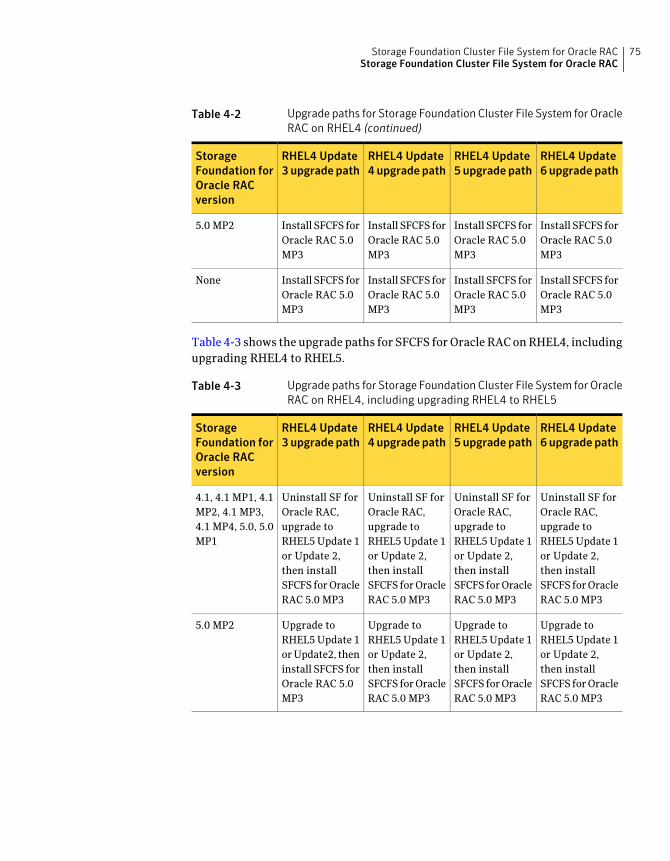
Table 4-2 Upgrade paths for Storage Foundation Cluster File System for OracleRAC on RHEL4 (continued)
RHEL4 Update6 upgrade path
RHEL4 Update5upgradepath
RHEL4 Update4upgradepath
RHEL4 Update3upgradepath
StorageFoundation forOracle RACversion
Install SFCFS forOracle RAC 5.0MP3
Install SFCFS forOracle RAC 5.0MP3
Install SFCFS forOracle RAC 5.0MP3
Install SFCFS forOracle RAC 5.0MP3
5.0 MP2
Install SFCFS forOracle RAC 5.0MP3
Install SFCFS forOracle RAC 5.0MP3
Install SFCFS forOracle RAC 5.0MP3
Install SFCFS forOracle RAC 5.0MP3
None
Table 4-3 shows the upgrade paths for SFCFS for Oracle RAC on RHEL4, includingupgrading RHEL4 to RHEL5.
Table 4-3 Upgrade paths for Storage Foundation Cluster File System for OracleRAC on RHEL4, including upgrading RHEL4 to RHEL5
RHEL4 Update6 upgrade path
RHEL4 Update5upgradepath
RHEL4 Update4upgradepath
RHEL4 Update3upgradepath
StorageFoundation forOracle RACversion
Uninstall SF forOracle RAC,upgrade toRHEL5 Update 1or Update 2,then installSFCFS for OracleRAC 5.0 MP3
Uninstall SF forOracle RAC,upgrade toRHEL5 Update 1or Update 2,then installSFCFS for OracleRAC 5.0 MP3
Uninstall SF forOracle RAC,upgrade toRHEL5 Update 1or Update 2,then installSFCFS for OracleRAC 5.0 MP3
Uninstall SF forOracle RAC,upgrade toRHEL5 Update 1or Update 2,then installSFCFS for OracleRAC 5.0 MP3
4.1, 4.1 MP1, 4.1MP2, 4.1 MP3,4.1 MP4, 5.0, 5.0MP1
Upgrade toRHEL5 Update 1or Update 2,then installSFCFS for OracleRAC 5.0 MP3
Upgrade toRHEL5 Update 1or Update 2,then installSFCFS for OracleRAC 5.0 MP3
Upgrade toRHEL5 Update 1or Update 2,then installSFCFS for OracleRAC 5.0 MP3
Upgrade toRHEL5 Update 1or Update2, theninstall SFCFS forOracle RAC 5.0MP3
5.0 MP2
75Storage Foundation Cluster File System for Oracle RACStorage Foundation Cluster File System for Oracle RAC
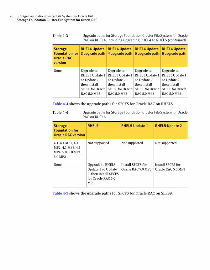
Table 4-3 Upgrade paths for Storage Foundation Cluster File System for OracleRAC on RHEL4, including upgrading RHEL4 to RHEL5 (continued)
RHEL4 Update6 upgrade path
RHEL4 Update5upgradepath
RHEL4 Update4upgradepath
RHEL4 Update3upgradepath
StorageFoundation forOracle RACversion
Upgrade toRHEL5 Update 1or Update 2,then installSFCFS for OracleRAC 5.0 MP3
Upgrade toRHEL5 Update 1or Update 2,then installSFCFS for OracleRAC 5.0 MP3
Upgrade toRHEL5 Update 1or Update 2,then installSFCFS for OracleRAC 5.0 MP3
Upgrade toRHEL5 Update 1or Update 2,then installSFCFS for OracleRAC 5.0 MP3
None
Table 4-4 shows the upgrade paths for SFCFS for Oracle RAC on RHEL5.
Table 4-4 Upgrade paths for Storage Foundation Cluster File System for OracleRAC on RHEL5
RHEL5 Update 2RHEL5 Update 1RHEL5StorageFoundation forOracle RAC version
Not supportedNot supportedNot supported4.1, 4.1 MP1, 4.1MP2, 4.1 MP3, 4.1MP4, 5.0, 5.0 MP1,5.0 MP2
Install SFCFS forOracle RAC 5.0 MP3
Install SFCFS forOracle RAC 5.0 MP3
Upgrade to RHEL5Update 1 or Update2, then install SFCFSfor Oracle RAC 5.0MP3
None
Table 4-3 shows the upgrade paths for SFCFS for Oracle RAC on SLES9.
Storage Foundation Cluster File System for Oracle RACStorage Foundation Cluster File System for Oracle RAC
76
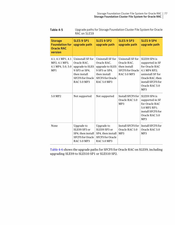
Table 4-5 Upgrade paths for Storage Foundation Cluster File System for OracleRAC on SLES9
SLES 9 SP4upgrade path
SLES 9 SP3upgrade path
SLES 9 SP2upgrade path
SLES 9 SP1upgrade path
StorageFoundation forOracle RACversion
SLES9 SP4 issupported in SFfor Oracle RAC4.1 MP4 RP2;uninstall SF forOracle RAC, theninstall SFCFS forOracle RAC 5.0MP3
Uninstall SF forOracle RAC,then installSFCFS for OracleRAC 5.0 MP3
Uninstall SF forOracle RAC,upgrade to SLES9 SP3 or SP4,then installSFCFS for OracleRAC 5.0 MP3
Uninstall SF forOracle RAC,upgrade to SLES9 SP3 or SP4,then installSFCFS for OracleRAC 5.0 MP3
4.1, 4.1 MP1, 4.1MP2, 4.1 MP3,4.1 MP4, 5.0, 5.0MP1
SLES9 SP4 issupported in SFfor Oracle RAC5.0 MP2 RP1;install SFCFS forOracle RAC 5.0MP3
Install SFCFS forOracle RAC 5.0MP3
Not supportedNot supported5.0 MP2
Install SFCFS forOracle RAC 5.0MP3
Install SFCFS forOracle RAC 5.0MP3
Upgrade toSLES9 SP3 orSP4, then installSFCFS for OracleRAC 5.0 MP3
Upgrade toSLES9 SP3 orSP4, then installSFCFS for OracleRAC 5.0 MP3
None
Table 4-6 shows the upgrade paths for SFCFS for Oracle RAC on SLES9, includingupgrading SLES9 to SLES10 SP1 or SLES10 SP2.
77Storage Foundation Cluster File System for Oracle RACStorage Foundation Cluster File System for Oracle RAC
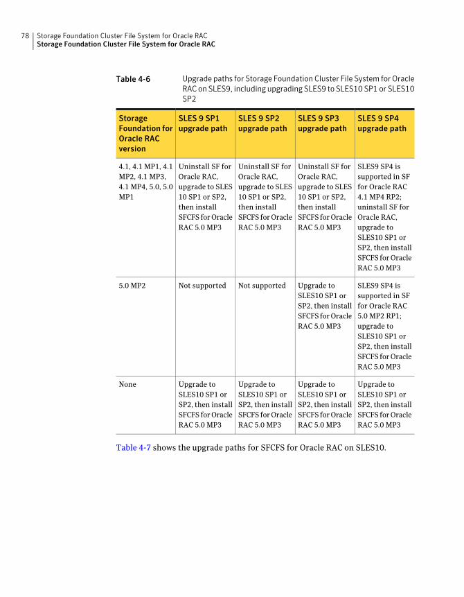
Table 4-6 Upgrade paths for Storage Foundation Cluster File System for OracleRAC on SLES9, including upgrading SLES9 to SLES10 SP1 or SLES10SP2
SLES 9 SP4upgrade path
SLES 9 SP3upgrade path
SLES 9 SP2upgrade path
SLES 9 SP1upgrade path
StorageFoundation forOracle RACversion
SLES9 SP4 issupported in SFfor Oracle RAC4.1 MP4 RP2;uninstall SF forOracle RAC,upgrade toSLES10 SP1 orSP2, then installSFCFS for OracleRAC 5.0 MP3
Uninstall SF forOracle RAC,upgrade to SLES10 SP1 or SP2,then installSFCFS for OracleRAC 5.0 MP3
Uninstall SF forOracle RAC,upgrade to SLES10 SP1 or SP2,then installSFCFS for OracleRAC 5.0 MP3
Uninstall SF forOracle RAC,upgrade to SLES10 SP1 or SP2,then installSFCFS for OracleRAC 5.0 MP3
4.1, 4.1 MP1, 4.1MP2, 4.1 MP3,4.1 MP4, 5.0, 5.0MP1
SLES9 SP4 issupported in SFfor Oracle RAC5.0 MP2 RP1;upgrade toSLES10 SP1 orSP2, then installSFCFS for OracleRAC 5.0 MP3
Upgrade toSLES10 SP1 orSP2, then installSFCFS for OracleRAC 5.0 MP3
Not supportedNot supported5.0 MP2
Upgrade toSLES10 SP1 orSP2, then installSFCFS for OracleRAC 5.0 MP3
Upgrade toSLES10 SP1 orSP2, then installSFCFS for OracleRAC 5.0 MP3
Upgrade toSLES10 SP1 orSP2, then installSFCFS for OracleRAC 5.0 MP3
Upgrade toSLES10 SP1 orSP2, then installSFCFS for OracleRAC 5.0 MP3
None
Table 4-7 shows the upgrade paths for SFCFS for Oracle RAC on SLES10.
Storage Foundation Cluster File System for Oracle RACStorage Foundation Cluster File System for Oracle RAC
78
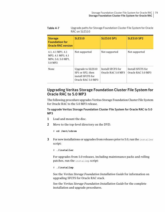
Table 4-7 Upgrade paths for Storage Foundation Cluster File System for OracleRAC on SLES10
SLES10 SP2SLES10 SP1SLES10StorageFoundation forOracle RAC version
Not supportedNot supportedNot supported4.1, 4.1 MP1, 4.1MP2, 4.1 MP3, 4.1MP4, 5.0, 5.0 MP1,5.0 MP2
Install SFCFS forOracle RAC 5.0 MP3
Install SFCFS forOracle RAC 5.0 MP3
Upgrade to SLES10SP1 or SP2, theninstall SFCFS forOracle RAC 5.0 MP3
None
Upgrading Veritas Storage Foundation Cluster File System forOracle RAC to 5.0 MP3The following procedure upgrades Veritas Storage Foundation Cluster File Systemfor Oracle RAC to the 5.0 MP3 release.
To upgrade Veritas Storage Foundation Cluster File System for Oracle RAC to 5.0MP3
1 Load and mount the disc.
2 Move to the top-level directory on the DVD.
# cd /mnt/cdrom
3 For new installations or upgrades from releases prior to 5.0, run theinstallerscript:
# ./installer
For upgrades from 5.0 releases, including maintenance packs and rollingpatches, run the installmp script:
# ./installmp
See the Veritas Storage Foundation Installation Guide for information onupgrading SFCFS for Oracle RAC stack.
See the Veritas Storage Foundation Installation Guide for the completeinstallation and upgrade procedures.
79Storage Foundation Cluster File System for Oracle RACStorage Foundation Cluster File System for Oracle RAC
Upgrading Oracle DatabaseAfter completing the SFCFS for Oracle RAC product upgrade, see one of thefollowing Oracle Metalink documents on the Oracle® Web site to upgrade OracleDatabase:
To upgrade Oracle Database to 10.2.0.4Oracle Metalink Doc ID 316889.1
To upgrade Oracle Database to 11.1.0.6Oracle Metalink Doc ID 429825.1
Storage Foundation Cluster File System for Oracle RACStorage Foundation Cluster File System for Oracle RAC
80
Fencing administration
This chapter includes the following topics:
■ I/O fencing
■ Troubleshooting fenced configurations
I/O fencingSymantec recommends configuring the cluster with I/O fencing enabled. I/Ofencing requires shared devices to support SCSI-3 Persistent Reservations (PR).Enabling I/O fencing prevents data corruption caused by a split brain scenario.
Symantec Storage Foundation Cluster File System is supported without I/O fencingenabled. However, without I/O fencing enabled, split brain scenarios can resultin data corruption.
Symantec Storage Foundation Cluster File System for Oracle RAC is supportedwithout I/O fencing enabled. However, without I/O fencing enabled, split brainscenarios can result in data corruption.
I/O fencing allows write access to members of the active cluster and blocks accessto non-members. The physical components of I/O fencing are data disks andcoordinator disks. Each has a unique purpose and uses different physical diskdevices.
See the Veritas Cluster Server Installation Guide.
See the Hardware Compatibility List (HCL) at the following URL:
http://support.veritas.com/docs/283161
Data disksData disks are standard disk devices used for data storage. These can be physicaldisks or RAID Logical Units (LUNs). These disks must support SCSI-3 PGR. Data
5Chapter
disks are incorporated in standard VxVM/CVM disk groups. CVM is responsiblefor fencing data disks on a disk-group basis. Because VxVM enables I/O fencing,several other features are also provided. Disks added to a group are automaticallyfenced, as are new paths to a device.
Coordinator DisksCoordinator disks are special-purpose disks. They comprise three (or an oddnumber greater than three) standard disks, or LUNs, set aside for use by I/Ofencing during cluster reconfiguration.
The coordinator disks act as a global lock device during a cluster reconfiguration.This lock mechanism determines which node is allowed to fence off data drivesfrom other nodes. From a high level, a system must eject a peer from thecoordinator disks before it can fence the peer from the data drives. This conceptof “racing” for control of coordinator disks is the key to understanding how fencinghelps prevent split-brain.
Coordinator disks cannot be used for any other purpose. You cannot store dataon them, or include them in a disk group for user data. They can be any threedisks that support SCSI-3 PGR. Symantec recommends the coordinator disks usethe smallest LUNs. Because coordinator disks do not store data, cluster nodesneed only register with them, not reserve them.
Before you configure coordinator disksI/O fencing requires coordinator disks to be configured in a disk group that eachcluster system can access. The use of coordinator disks enables the vxfen driverto resolve potential split-brain conditions and prevent data corruption. Acoordinator disk is not used for data storage, so it can be configured as the smallestLUN on a disk array to avoid wasting space.
Coordinator disks must meet the following requirements:
■ There must be at least three coordinator disks and the total number ofcoordinator disks must be an odd number. This ensures a majority of diskscan be achieved.
■ Each of the coordinator disks must use a physically separate disk or LUN.
■ Each of the coordinator disks should be on a different disk array, if possible.
■ Coordinator disks in a disk array should use hardware-based mirroring.
■ The coordinator disks must support SCSI-3 PR. Note that the use of thevxfentsthdw utility to test for SCSI-3 PR support requires that disks be 1MBor greater. Smaller disks can be tested manually.
Fencing administrationI/O fencing
82
Contact Veritas support (http://support.veritas.com) for the procedure.
Setting up the disk group for coordinator disksThis section describes setting up the disk group for coordinator disks.
To set up the disk group for coordinator disks
1 If you have already added and initialized disks you intend to use as coordinatordisks, you can begin the following procedure at 5.
2 Physically add the three disks you intend to use for coordinator disks. Allcluster nodes should physically share them. Symantec Corporationrecommends that you use the smallest size disks or LUNs, so that space fordata is not wasted.
3 If necessary, use the vxdisk scandisks command to scan the disk drives andtheir attributes. This command updates the VxVM device list and reconfiguresDMP with the new devices. For example:
# vxdisk scandisks
4 Use the command vxdisksetup command to initialize a disk as a VxVM disk.The example command that follows specifies the CDS format:
# vxdisksetup -i vxvm_device_name format=cdsdisk
For example:
5 From one node, create a disk group named vxfencoorddg. This group mustcontain an odd number of disks or LUNs and a minimum of three disks.Symantec recommends that you use only three coordinator disks, and thatyou use the smallest size disks or LUNs to conserve disk space.
For example, assume the disks have the device names EMC0_12, EMC0_16,and EMC0_17.
6 On any node, create the disk group by specifying the device name of one ofthe disks.
# vxdg -o coordinator=on init vxfencoorddg EMC0_12
Requirements for testing the coordinator disk groupReview the requirments for testing the coordinator disk group.
Run the vxfentsthdw utility
Review the following guidelines on testing support for SCSI-3:
83Fencing administrationI/O fencing
■ The utility requires that the coordinator disk group be accessible from twosystems. For example, if you have a four-system cluster, select any two systemsfor the test.
■ If you configured ssh (SSH client) for the cluster nodes, VXFENTSTHDW canbe used as long as ssh commands between nodes can execute without passwordprompting and confirmation.If you did not configure ssh, enable each node to have remote rsh access tothe other nodes during installation and disk verification. On each node, placinga “+” character in the first line of the /.rhosts file gives remote access to thesystem running the install program. You can limit the remote access to specificnodes. Refer to the manual page for the /.rhosts file for more information.Remove the remote rsh access permissions after the installation and diskverification process.
■ ssh is used by default and rsh is only used if you do use the vxfentsthdw -n
command.
■ To ensure both nodes are connected to the same disk during the test, use thevxfenadm -i diskpath command to verify the disk serial number.
■ The vxfentsthdwutility has additional options suitable for testing many disks.You can test disks without destroying data using the -r option. The optionsfor testing disk groups (-g) and disks listed in a file (-f) are described in detail:
Testing the coordinator disk groupThis section describes testing the coordinator disk group.
To test the coordinator disk group
1 To start the utility from one node, type the following command:#/opt/VRTSvcs/vxfen/bin/vxfentsthdw
Make sure system-to-system communication is functioning properly beforeperforming this step.
See the vxfentsthdw(1M) man page.
2 After reviewing the overview and warning about overwriting data on thedisks, confirm to continue the process and enter the node names.
3 Enter the name of the disk you are checking.
Creating the vxfendg fileThis section describes creating the vxfendg file.
Fencing administrationI/O fencing
84
To create the vxfendg file
1 To deport the disk group, type the following command:
# vxdg deport vxfencoorddg
2 Import the disk group with the -t option to avoid automatically importing itwhen the nodes restart:
# vxdg -t import vxfencoorddg
3 Deport the disk group. This operation prevents the coordinator disks fromserving other purposes:
# vxdg deport vxfencoorddg
4 On all nodes, type:
# echo "vxfencoorddg" > /etc/vxfendg
Do no use spaces between the quotes in the “vxfencoorddg” text.
This command creates the /etc/vxfendg file, which includes the name ofthe coordinator disk group. Based on the contents of the /etc/vxfendg file,the rc script creates the /etc/vxfentab file for use by the vxfen driver whenthe system starts. The rc script also invokes the vxfenconfig command,which configures the vxfendriver to start and use the coordinator disks listedin /etc/vxfentab. /etc/vxfentab is a generated file; do not modify this file.
Adding or removing coordinator disksBefore adding coordinator disks, verify the disks support SCSI-3 persistentreservations.
85Fencing administrationI/O fencing
To add and remove coordinator disks
1 Log in as root on any cluster node.
2 Import the coordinator disk group. The file /etc/vxfendg includes the nameof the disk group containing the coordinator disks. Type:
# vxdg -tfC import ‘cat /etc/vxfendg‘
where:
Specifies that the disk group is imported only until the systemreboots.
-t
Specifies that the import is to be done forcibly, which is necessaryif one or more disks is inaccessible.
-f
Specifies any import blocks are removed.-C
3 To add disks to, or remove them from, the disk group, use the VxVM diskadministrator utility, vxdiskadm.
4 After disks are added or removed, deport the disk group:
# vxdg deport ‘cat /etc/vxfendg‘
5 Reboot each system in the cluster to make the coordinator disks accessible.
Verifying fenced configurationsAdministrators can use the vxfenadm command to test and troubleshoot fencedconfigurations. The vxfenadm command includes the following options:
Display current I/O fencing mode-d
Read and display keys-g
Read SCSI inquiry information from device-i
Register with disks-m
make a reservation with disks-n
Remove registrations made by other systems-p
Read reservations-r
Remove registrations-x
Fencing administrationI/O fencing
86
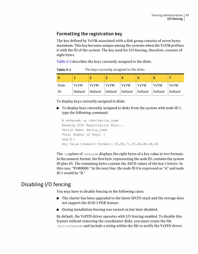
Formatting the registration keyThe key defined by VxVM associated with a disk group consists of seven bytesmaximum. This key becomes unique among the systems when the VxVM prefixesit with the ID of the system. The key used for I/O fencing, therefore, consists ofeight bytes.
Table 5-2 describes the keys currently assigned to the disks.
Table 5-1 The keys currently assigned to the disks
76543210
VxVM
Defined
VxVM
Defined
VxVM
Defined
VxVM
Defined
VxVM
Defined
VxVM
Defined
VxVM
Defined
Node
ID
To display keys currently assigned to disks
■ To display keys currently assigned to disks from the system with node ID 1,type the following command:
# vxfenadm -g /dev/device_name
Reading SCSI Registration Keys...
Device Name: device_name
Total Number of Keys: 1
key[0]:
Key Value [Numeric Format]: 65,80,71,82,48,48,48,48
The -g option of vxfenadm displays the eight bytes of a key value in two formats.In the numeric format, the first byte, representing the node ID, contains the systemID plus 65. The remaining bytes contain the ASCII values of the key’s letters. Inthis case, “PGR0000.” In the next line, the node ID 0 is expressed as “A” and nodeID 1 would be “B.”
Disabling I/O fencingYou may have to disable fencing in the following cases:
■ The cluster has been upgraded to the latest SFCFS stack and the storage doesnot support the SCSI-3 PGR feature.
■ During installation fencing was turned on but later disabled.
By default, the VxFEN driver operates with I/O fencing enabled. To disable thisfeature without removing the coordinator disks, you must create the file/etc/vxfenmode and include a string within the file to notify the VxFEN driver.
87Fencing administrationI/O fencing
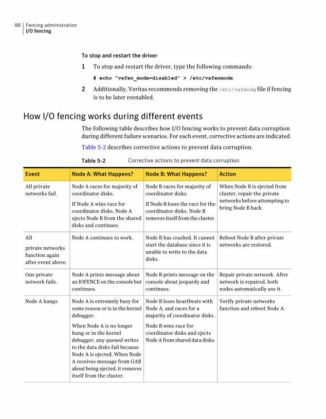
To stop and restart the driver
1 To stop and restart the driver, type the following commands:
# echo "vxfen_mode=disabled" > /etc/vxfenmode
2 Additionally, Veritas recommends removing the /etc/vxfendg file if fencingis to be later reenabled.
How I/O fencing works during different eventsThe following table describes how I/O fencing works to prevent data corruptionduring different failure scenarios. For each event, corrective actions are indicated.
Table 5-2 describes corrective actions to prevent data corruption.
Table 5-2 Corrective actions to prevent data corruption
ActionNode B: What Happens?Node A: What Happens?Event
When Node B is ejected fromcluster, repair the privatenetworks before attempting tobring Node B back.
Node B races for majority ofcoordinator disks.
If Node B loses the race for thecoordinator disks, Node Bremoves itself from the cluster.
Node A races for majority ofcoordinator disks.
If Node A wins race forcoordinator disks, Node Aejects Node B from the shareddisks and continues.
All privatenetworks fail.
Reboot Node B after privatenetworks are restored.
Node B has crashed. It cannotstart the database since it isunable to write to the datadisks.
Node A continues to work.All
private networksfunction againafter event above.
Repair private network. Afternetwork is repaired, bothnodes automatically use it.
Node B prints message on theconsole about jeopardy andcontinues.
Node A prints message aboutan IOFENCE on the console butcontinues.
One privatenetwork fails.
Verify private networksfunction and reboot Node A.
Node B loses heartbeats withNode A, and races for amajority of coordinator disks.
Node B wins race forcoordinator disks and ejectsNode A from shared data disks.
Node A is extremely busy forsome reason or is in the kerneldebugger.
When Node A is no longerhung or in the kerneldebugger, any queued writesto the data disks fail becauseNode A is ejected. When NodeA receives message from GABabout being ejected, it removesitself from the cluster.
Node A hangs.
Fencing administrationI/O fencing
88
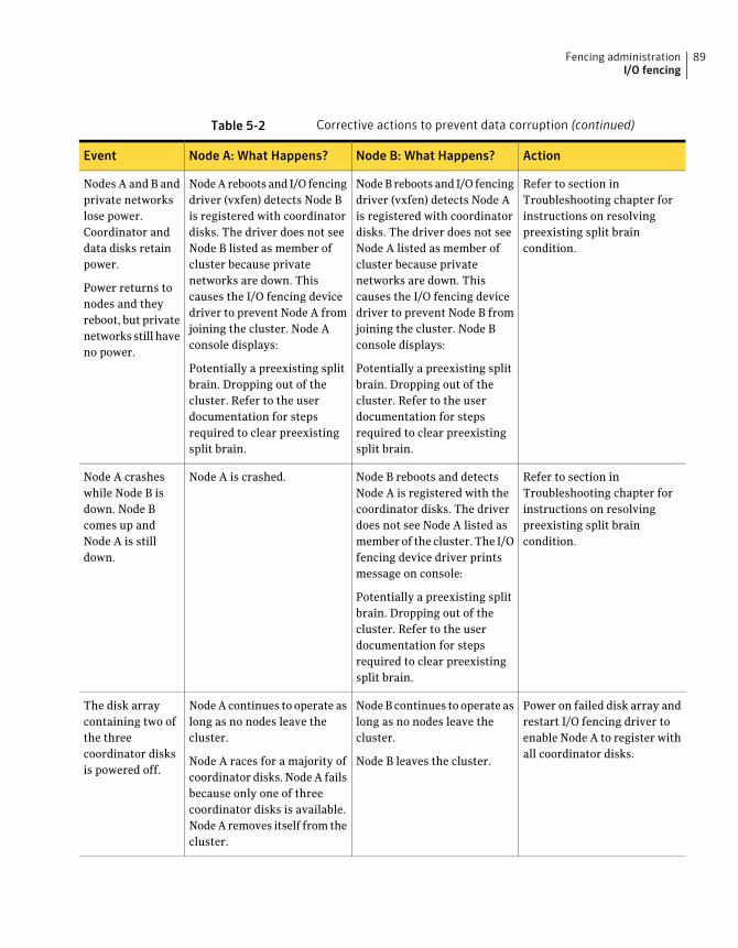
Table 5-2 Corrective actions to prevent data corruption (continued)
ActionNode B: What Happens?Node A: What Happens?Event
Refer to section inTroubleshooting chapter forinstructions on resolvingpreexisting split braincondition.
Node B reboots and I/O fencingdriver (vxfen) detects Node Ais registered with coordinatordisks. The driver does not seeNode A listed as member ofcluster because privatenetworks are down. Thiscauses the I/O fencing devicedriver to prevent Node B fromjoining the cluster. Node Bconsole displays:
Potentially a preexisting splitbrain. Dropping out of thecluster. Refer to the userdocumentation for stepsrequired to clear preexistingsplit brain.
Node A reboots and I/O fencingdriver (vxfen) detects Node Bis registered with coordinatordisks. The driver does not seeNode B listed as member ofcluster because privatenetworks are down. Thiscauses the I/O fencing devicedriver to prevent Node A fromjoining the cluster. Node Aconsole displays:
Potentially a preexisting splitbrain. Dropping out of thecluster. Refer to the userdocumentation for stepsrequired to clear preexistingsplit brain.
Nodes A and B andprivate networkslose power.Coordinator anddata disks retainpower.
Power returns tonodes and theyreboot, but privatenetworks still haveno power.
Refer to section inTroubleshooting chapter forinstructions on resolvingpreexisting split braincondition.
Node B reboots and detectsNode A is registered with thecoordinator disks. The driverdoes not see Node A listed asmember of the cluster. The I/Ofencing device driver printsmessage on console:
Potentially a preexisting splitbrain. Dropping out of thecluster. Refer to the userdocumentation for stepsrequired to clear preexistingsplit brain.
Node A is crashed.Node A crasheswhile Node B isdown. Node Bcomes up andNode A is stilldown.
Power on failed disk array andrestart I/O fencing driver toenable Node A to register withall coordinator disks.
Node B continues to operate aslong as no nodes leave thecluster.
Node B leaves the cluster.
Node A continues to operate aslong as no nodes leave thecluster.
Node A races for a majority ofcoordinator disks. Node A failsbecause only one of threecoordinator disks is available.Node A removes itself from thecluster.
The disk arraycontaining two ofthe threecoordinator disksis powered off.
89Fencing administrationI/O fencing
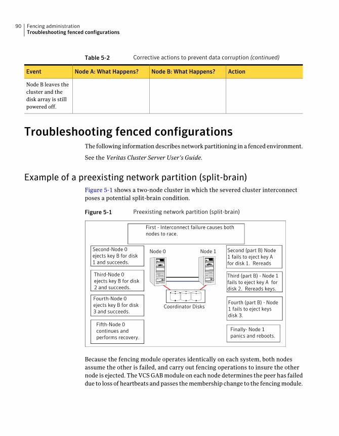
Table 5-2 Corrective actions to prevent data corruption (continued)
ActionNode B: What Happens?Node A: What Happens?Event
Node B leaves thecluster and thedisk array is stillpowered off.
Troubleshooting fenced configurationsThe following information describes network partitioning in a fenced environment.
See the Veritas Cluster Server User’s Guide.
Example of a preexisting network partition (split-brain)Figure 5-1 shows a two-node cluster in which the severed cluster interconnectposes a potential split-brain condition.
Figure 5-1 Preexisting network partition (split-brain)
Second-Node 0ejects key B for disk1 and succeeds.
Node 0 Node 1
Coordinator Disks
Finally- Node 1panics and reboots.
First - Interconnect failure causes bothnodes to race.
Third-Node 0ejects key B for disk2 and succeeds.
Fourth-Node 0ejects key B for disk3 and succeeds.
Fifth-Node 0continues andperforms recovery.
Second (part B) Node1 fails to eject key Afor disk 1. Rereads
Third (part B) - Node 1fails to eject key A fordisk 2. Rereads keys.
Fourth (part B) - Node1 fails to eject keysdisk 3.
Because the fencing module operates identically on each system, both nodesassume the other is failed, and carry out fencing operations to insure the othernode is ejected. The VCS GAB module on each node determines the peer has faileddue to loss of heartbeats and passes the membership change to the fencing module.
Fencing administrationTroubleshooting fenced configurations
90
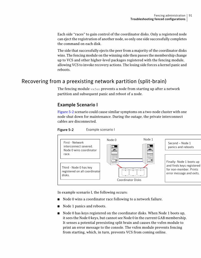
Each side “races” to gain control of the coordinator disks. Only a registered nodecan eject the registration of another node, so only one side successfully completesthe command on each disk.
The side that successfully ejects the peer from a majority of the coordinator diskswins. The fencing module on the winning side then passes the membership changeup to VCS and other higher-level packages registered with the fencing module,allowing VCS to invoke recovery actions. The losing side forces a kernel panic andreboots.
Recovering from a preexisting network partition (split-brain)The fencing module vxfen prevents a node from starting up after a networkpartition and subsequent panic and reboot of a node.
Example Scenario IFigure 5-2 scenario could cause similar symptoms on a two-node cluster with onenode shut down for maintenance. During the outage, the private interconnectcables are disconnected.
Figure 5-2 Example scenario I
Node 0 Node 1
Coordinator Disks
First - Networkinterconnect severed.Node 0 wins coordinatorrace.
Third - Node 0 has keyregistered on all coordinatordisks.
Second – Node 1panics and reboots
Finally- Node 1 boots upand finds keys registeredfor non-member. Printserror message and exits.
In example scenario I, the following occurs:
■ Node 0 wins a coordinator race following to a network failure.
■ Node 1 panics and reboots.
■ Node 0 has keys registered on the coordinator disks. When Node 1 boots up,it sees the Node 0 keys, but cannot see Node 0 in the current GAB membership.It senses a potential preexisting split brain and causes the vxfen module toprint an error message to the console. The vxfen module prevents fencingfrom starting, which, in turn, prevents VCS from coming online.
91Fencing administrationTroubleshooting fenced configurations
Suggested solution: Shut down Node 1, reconnect the cables, and restart Node1.
Example Scenario IISimilar to example scenario I, if private interconnect cables are disconnected ina two-node cluster, Node 1 is fenced out of the cluster, panics, and reboots. Ifbefore the private interconnect cables are fixed and Node 1 rejoins the cluster,Node 0 reboots and remote (or just reboots). No node can write to the data disksuntil the private networks are fixed. This is because GAB membership cannot beformed, therefore the cluster cannot be formed.
Suggested solution: Shut down both nodes, reconnect the cables, restart the nodes.
Example Scenario IIISimilar to example scenario II, if private interconnect cables are disconnected ina two-node cluster, Node 1 is fenced out of the cluster, panics, and reboots. Ifbefore the private interconnect cables are fixed and Node 1 rejoins the cluster,Node 0 panics due to hardware failure and cannot come back up, Node 1 cannotrejoin.
Suggested solution: Shut down Node 1, reconnect the cables, restart the node.You must then clear the registration of Node 0 from the coordinator disks.
To fix scenario III
1 On Node 1, type the following command:
# /opt/VRTSvcs/vxfen/bin/vxfenclearpre
2 Restart the node.
Fencing administrationTroubleshooting fenced configurations
92
Using Veritas Extension forOracle Disk Manager
This chapter includes the following topics:
■ About Oracle Disk Manager
■ About Oracle Disk Manager and Storage Foundation Cluster Files System
■ About Oracle Disk Manager and Oracle Managed Files
■ Setting up Veritas Extension for Oracle Disk Manager
■ Configuring Veritas Extension for Oracle Disk Manager
■ How to prepare existing database storage for Oracle Disk Manager
■ Verifying that Oracle Disk Manager is configured
■ Disabling the Oracle Disk Manager feature
About Oracle Disk ManagerVeritas Extension for Oracle Disk Manager is specifically designed for Oracle9ior later to enhance file management and disk I/O throughput. The features ofOracle Disk Manager are best suited for databases that reside in a file systemcontained in Veritas File System. Oracle Disk Manager allows Oracle9i or laterusers to improve database throughput for I/O intensive workloads with specialI/O optimization.
Veritas Extension for Oracle Disk Manager supports Oracle Resilvering. WithOracle Resilvering, the storage layer receives information from the Oracle databaseas to which regions or blocks of a mirrored datafile to resync after a system crash.
6Chapter
When using Oracle Resilvering, you can turn off VxVM Dirty Region Logging(DRL), which increases performance.
Oracle Disk Manager reduces administrative overhead by providing enhancedsupport for Oracle Managed Files. Veritas Extension for Oracle Disk Manager istransparent to the user. Files managed using Veritas Extension for Oracle DiskManager do not require special file naming conventions. The Oracle Disk Managerinterface uses regular database files.
Note: Veritas Storage Foundation 4.1 for Oracle was the last major release thatsupported Oracle Disk Manager for raw devices.
Database administrators can choose the datafile type used with the Oracle product.Historically, choosing between file system files and raw devices was based onmanageability and performance. The exception to this is a database intended foruse with Oracle Parallel Server, which requires raw devices on most platforms. Ifperformance is not as important as administrative ease, file system files aretypically the preferred file type. However, while an application may not havesubstantial I/O requirements when it is first implemented, I/O requirements maychange. If an application becomes dependent upon I/O throughput, convertingdatafiles from file system to raw devices is often necessary.
Oracle Disk Manager was designed to work with Oracle9i or later to provide bothperformance and manageability. Oracle Disk Manager provides support for Oracle'sfile management and I/O calls for database storage on VxFS file systems and onraw volumes or partitions. This feature is provided as a dynamically-loaded sharedlibrary with which Oracle binds when it is loaded. The Oracle Disk Manager libraryworks with an Oracle Disk Manager driver that is loaded in the kernel to performits functions.
The benefits of using Oracle Disk Manager are:
■ True kernel asynchronous I/O for files and raw devices
■ Reduced system call overhead
■ Improved file system layout by preallocating contiguous files on a VxFS filesystem
■ Performance on file system files that is equivalent to raw devices
■ Transparent to users
■ Contiguous datafile allocation
Using Veritas Extension for Oracle Disk ManagerAbout Oracle Disk Manager
94
How Oracle Disk Manager improves database performanceOracle Disk Manager improves database I/O performance to VxFS file systemsby:
■ Supporting kernel asynchronous I/O
■ Supporting direct I/O and avoiding double buffering
■ Avoiding kernel write locks on database files
■ Supporting many concurrent I/Os in one system call
■ Avoiding duplicate opening of files per Oracle instance
■ Allocating contiguous datafiles
About kernel asynchronous I/O supportAsynchronous I/O performs non-blocking system level reads and writes, allowingthe system to perform multiple I/O requests simultaneously. Kernel asynchronousI/O is better than library asynchronous I/O because the I/O is queued to the diskdevice drivers in the kernel, minimizing context switches to accomplish the work.
About direct I/O support and avoiding double bufferingI/O on files using read() and write() system calls typically results in data beingcopied twice: once between the user and kernel space, and the other betweenkernel space and the disk. In contrast, I/O on raw devices is copied directly betweenuser space and disk, saving one level of copying. As with I/O on raw devices, OracleDisk Manager I/O avoids the extra copying. Oracle Disk Manager bypasses thesystem cache and accesses the files with the same efficiency as raw devices.Avoiding double buffering reduces the memory overhead on the system.Eliminating the copies from kernel to user address space significantly reduceskernel mode processor utilization freeing more processor cycles to execute theapplication code.
About avoiding kernel write locks on database filesWhen database I/O is performed by way of the write() system call, each systemcall acquires and releases a kernel write lock on the file. This lock preventssimultaneous write operations on the same file. Because database systems usuallyimplement their own locks for managing concurrent access to files, write locksunnecessarily serialize I/O writes. Oracle Disk Manager bypasses file systemlocking and lets the database server control data access.
95Using Veritas Extension for Oracle Disk ManagerAbout Oracle Disk Manager
About supporting many concurrent I/Os in one system callWhen performing asynchronous I/O, an Oracle process may try to issue additionalI/O requests while collecting completed I/Os, or it may try to wait for particularI/O requests synchronously, as it can do no other work until the I/O is completed.The Oracle process may also try to issue requests to different files. All this activitycan be accomplished with one system call when Oracle uses the Oracle DiskManager I/O interface. This interface reduces the number of system callsperformed to accomplish the same work, reducing the number of user space/kernelspace context switches.
About avoiding duplicate file opensOracle Disk Manager allows files to be opened once, providing a “file identifier.”This is called “identifying” the files. The same file identifiers can be used by anyother processes in the Oracle instance. The file status is maintained by the OracleDisk Manager driver in the kernel. The reduction in file open calls reducesprocessing overhead at process initialization and termination, and it reduces thenumber of file status structures required in the kernel.
About allocating contiguous datafilesOracle Disk Manager can improve performance for queries, such as sort andparallel queries, that use temporary tablespaces. Without Oracle Disk Manager,Oracle does not initialize the datafiles for the temporary tablespaces. Therefore,the datafiles become sparse files and are generally fragmented. Sparse orfragmented files lead to poor query performance. When using Oracle Disk Manager,the datafiles are initialized for the temporary tablespaces and are allocated in acontiguous fashion, so that they are not sparse.
About Oracle Disk Manager and Storage FoundationCluster Files System
Oracle Disk Manager supports access to clustered files in the SFCFS environment.With a Veritas Storage Foundation Cluster File System license, ODM supportsSFCFS files in a serially-exclusive mode which allows access to each SFCFS fileby one node at a time, but does not allow simultaneous access from multiple nodes.
See the mount.vxodmfs(8) man page for more information on its cluster supportmodes.
Using Veritas Extension for Oracle Disk ManagerAbout Oracle Disk Manager and Storage Foundation Cluster Files System
96
AboutOracle DiskManager andOracleManaged FilesOracle9i or later offers a feature known as Oracle Managed Files (OMF). OMFmanages datafile attributes such as file names, file location, storage attributes,and whether or not the file is in use by the database. OMF is only supported fordatabases that reside in file systems. OMF functionality is greatly enhanced byOracle Disk Manager.
The main requirement for OMF is that the database be placed in file system files.There are additional prerequisites imposed upon the file system itself.
OMF is a file management feature that:
■ Eliminates the task of providing unique file names
■ Offers dynamic space management by way of the tablespace auto-extendfunctionality of Oracle9i or later
OMF should only be used in file systems that reside within striped logical volumes,which support dynamic file system growth. File systems intended for OMF usemust also support large, extensible files in order to facilitate tablespaceauto-extension. Raw partitions cannot be used for OMF.
By default, OMF datafiles are created with auto-extend capability. This attributereduces capacity planning associated with maintaining existing databases andimplementing new applications. Due to disk fragmentation that occurs as thetablespace grows over time, database administrators have been somewhat cautiouswhen considering auto-extensible tablespaces. Oracle Disk Manager eliminatesthis concern.
When Oracle Disk Manager is used in conjunction with OMF, special care is givenwithin Veritas Extension for Disk Manager to ensure that contiguous disk spaceis allocated to datafiles, including space allocated to a tablespace when it isauto-extended. The table and index scan throughput does not decay as thetablespace grows.
How Oracle Disk Manager works with Oracle Managed FilesThe following example illustrates the relationship between Oracle Disk Managerand OMF.
Note:Before building an OMF database, you need the appropriate init.oradefaultvalues. These values control the location of the SYSTEM tablespace, online redologs, and control files after the CREATE DATABASE statement is executed.
97Using Veritas Extension for Oracle Disk ManagerAbout Oracle Disk Manager and Oracle Managed Files
This example shows the init.ora contents and the command for starting thedatabase instance. To simplify Oracle UNDO management, the new Oracle9i orlater init.ora parameter UNDO_MANAGEMENT is set to AUTO. This is known asSystem-Managed Undo.
$ cat initPROD.ora
UNDO_MANAGEMENT = AUTO
DB_CREATE_FILE_DEST = '/PROD'
DB_CREATE_ONLINE_LOG_DEST_1 = '/PROD'
db_block_size = 4096
db_name = PROD
$ sqlplus /nolog
SQL> connect / as sysdba
SQL> startup nomount pfile= initPROD.ora
The Oracle instance starts.
Total System Global Area 93094616 bytes
Fixed Size 279256 bytes
Variable Size 41943040 bytes
Database Buffers 50331648 bytes
Redo Buffers 540672 bytes
To implement a layout that places files associated with the EMP_TABLE tablespacein a directory separate from the EMP_INDEX tablespace, use the ALTER SYSTEM
statement. This example shows how OMF handles file names and storage clausesand paths. The layout allows you to think of the tablespaces as objects in a filesystem as opposed to a collection of datafiles. Since OMF uses the Oracle DiskManager file resize function, the tablespace files are initially created with thedefault size of 100MB and grow as needed. Use the MAXSIZE attribute to limitgrowth.
The following example shows the commands for creating an OMF database andfor creating the EMP_TABLE and EMP_INDEX tablespaces in their own locale.
Note: The directory must exist for OMF to work, so the SQL*Plus HOST commandis used to create the directories:
SQL> create database PROD;
The database is created.
SQL> HOST mkdir /PROD/EMP_TABLE;
SQL> ALTER SYSTEM SET DB_CREATE_FILE_DEST = '/PROD/EMP_TABLE';
Using Veritas Extension for Oracle Disk ManagerAbout Oracle Disk Manager and Oracle Managed Files
98
The system is altered.
SQL> create tablespace EMP_TABLE DATAFILE AUTOEXTEND ON MAXSIZE \
500M;
A tablespace is created.
SQL> ALTER SYSTEM SET DB_CREATE_FILE_DEST = '/PROD/EMP_INDEX';
The system is altered.
SQL> create tablespace EMP_INDEX DATAFILE AUTOEXTEND ON MAXSIZE \
100M;
A tablespace is created.
Use the ls command to show the newly created database:
$ ls -lFR
total 638062
drwxr-xr-x 2 oracle9i dba 96 May 3 15:43 EMP_INDEX/
drwxr-xr-x 2 oracle9i dba 96 May 3 15:43 EMP_TABLE/
-rw-r--r-- 1 oracle9i dba 104858112 May 3 17:28 ora_1_BEhYgc0m.log
-rw-r--r-- 1 oracle9i dba 104858112 May 3 17:27 ora_2_BEhYu4NA.log
-rw-r--r-- 1 oracle9i dba 806912 May 3 15:43 ora_BEahlfUX.ctl
-rw-r--r-- 1 oracle9i dba 10489856 May 3 15:43 ora_sys_undo_BEajPSVq.dbf
-rw-r--r-- 1 oracle9i dba 104861696 May 3 15:4 ora_system_BEaiFE8v.dbf
-rw-r--r-- 1 oracle9i dba 186 May 3 15:03 PROD.ora
./EMP_INDEX:
total 204808
-rw-r--r-- 1 oracle9i dba 104861696 May 3 15:43
ora_emp_inde_BEakGfun.dbf
./EMP_TABLE:
total 204808
-rw-r--r-- 1 oracle9i dba 104861696 May 3 15:43
ora_emp_tabl_BEak1LqK.dbf
Setting upVeritas Extension forOracleDiskManagerVeritas Extension for Oracle Disk Manager is part of Veritas Storage Foundationfor Oracle. Veritas Extension for Oracle Disk Manager is enabled once VeritasStorage Foundation for Oracle and Oracle9i or later are installed, and the Veritas
99Using Veritas Extension for Oracle Disk ManagerSetting up Veritas Extension for Oracle Disk Manager
Extension for Oracle Disk Manager library is linked to the library in the{ORACLE_HOME}/lib directory.
If you are performing a local Oracle installation, not on the SFCFS file system,then ODM linking needs to be performed on all nodes in the cluster.
Before setting up Veritas Extension for Oracle Disk Manager, the followingconditions must be met:
■ Veritas Storage Foundation for Oracle must be installed on yoursystem.
■ Oracle9i, or later, must be installed on your system.
■ If Cached Quick I/O is available, do not enable Oracle Disk Managerwhen Cached Quick I/O is enabled for datafiles. (Cached Quick I/Ois not available on Linux.)
Prerequisites
■ When the Quick I/O feature is available, Oracle Disk Manager usesthe Quick I/O driver to perform asynchronous I/O. Do not turn offthe Quick I/O mount option, which is the default. (Quick I/O is notavailable on Linux.)
■ Oracle uses default file access methods if Oracle9i or later orVeritas Storage Foundation for Oracle is not installed, or VxFS 5.0is not available in the kernel.
Usage Notes
ConfiguringVeritasExtension forOracleDiskManagerIf ORACLE_HOME is on a shared file system, run the following commands from anynode, otherwise run them on each node.
where ORACLE_HOME is the location where Oracle database binaries have beeninstalled.
To configure Veritas Extension for Oracle Disk Manager
1 Log in as oracle.
2 If the Oracle database is running, then shutdown the Oracle database.
3 Verify that /opt/VRTSodm/lib64/libodm.so exists.
4 Link Oracle's ODM library present in ORACLE_HOME with Veritas Extensionfor Oracle Disk Manager library:
For Oracle9i:
■ Change to the $ORACLE_HOME/lib directory, enter:
# cd $ORACLE_HOME/lib
Using Veritas Extension for Oracle Disk ManagerConfiguring Veritas Extension for Oracle Disk Manager
100
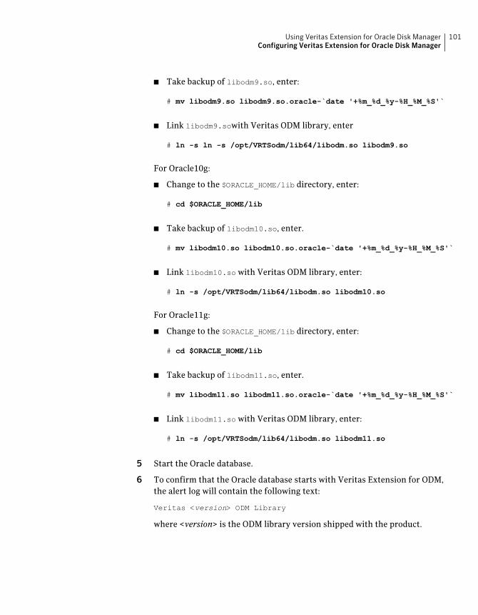
■ Take backup of libodm9.so, enter:
# mv libodm9.so libodm9.so.oracle-`date '+%m_%d_%y-%H_%M_%S'`
■ Link libodm9.sowith Veritas ODM library, enter
# ln -s ln -s /opt/VRTSodm/lib64/libodm.so libodm9.so
For Oracle10g:
■ Change to the $ORACLE_HOME/lib directory, enter:
# cd $ORACLE_HOME/lib
■ Take backup of libodm10.so, enter.
# mv libodm10.so libodm10.so.oracle-`date '+%m_%d_%y-%H_%M_%S'`
■ Link libodm10.so with Veritas ODM library, enter:
# ln -s /opt/VRTSodm/lib64/libodm.so libodm10.so
For Oracle11g:
■ Change to the $ORACLE_HOME/lib directory, enter:
# cd $ORACLE_HOME/lib
■ Take backup of libodm11.so, enter.
# mv libodm11.so libodm11.so.oracle-`date '+%m_%d_%y-%H_%M_%S'`
■ Link libodm11.so with Veritas ODM library, enter:
# ln -s /opt/VRTSodm/lib64/libodm.so libodm11.so
5 Start the Oracle database.
6 To confirm that the Oracle database starts with Veritas Extension for ODM,the alert log will contain the following text:
Veritas <version> ODM Library
where <version> is the ODM library version shipped with the product.
101Using Veritas Extension for Oracle Disk ManagerConfiguring Veritas Extension for Oracle Disk Manager
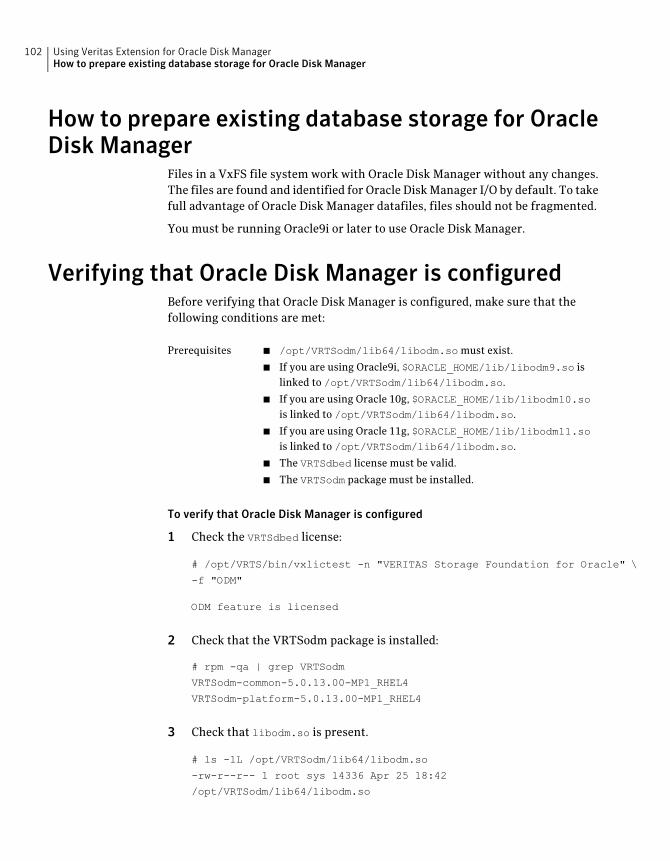
How to prepare existing database storage for OracleDisk Manager
Files in a VxFS file system work with Oracle Disk Manager without any changes.The files are found and identified for Oracle Disk Manager I/O by default. To takefull advantage of Oracle Disk Manager datafiles, files should not be fragmented.
You must be running Oracle9i or later to use Oracle Disk Manager.
Verifying that Oracle Disk Manager is configuredBefore verifying that Oracle Disk Manager is configured, make sure that thefollowing conditions are met:
■ /opt/VRTSodm/lib64/libodm.so must exist.
■ If you are using Oracle9i, $ORACLE_HOME/lib/libodm9.so islinked to /opt/VRTSodm/lib64/libodm.so.
■ If you are using Oracle 10g, $ORACLE_HOME/lib/libodm10.sois linked to /opt/VRTSodm/lib64/libodm.so.
■ If you are using Oracle 11g, $ORACLE_HOME/lib/libodm11.sois linked to /opt/VRTSodm/lib64/libodm.so.
■ The VRTSdbed license must be valid.
■ The VRTSodm package must be installed.
Prerequisites
To verify that Oracle Disk Manager is configured
1 Check the VRTSdbed license:
# /opt/VRTS/bin/vxlictest -n "VERITAS Storage Foundation for Oracle" \
-f "ODM"
ODM feature is licensed
2 Check that the VRTSodm package is installed:
# rpm -qa | grep VRTSodm
VRTSodm-common-5.0.13.00-MP1_RHEL4
VRTSodm-platform-5.0.13.00-MP1_RHEL4
3 Check that libodm.so is present.
# ls -lL /opt/VRTSodm/lib64/libodm.so
-rw-r--r-- 1 root sys 14336 Apr 25 18:42
/opt/VRTSodm/lib64/libodm.so
Using Veritas Extension for Oracle Disk ManagerHow to prepare existing database storage for Oracle Disk Manager
102
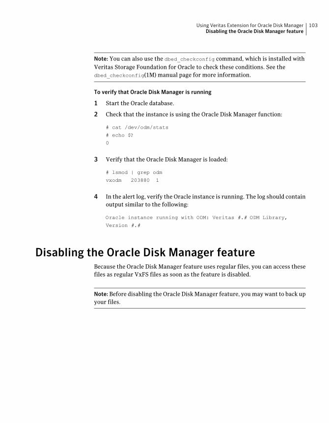
Note: You can also use the dbed_checkconfig command, which is installed withVeritas Storage Foundation for Oracle to check these conditions. See thedbed_checkconfig(1M) manual page for more information.
To verify that Oracle Disk Manager is running
1 Start the Oracle database.
2 Check that the instance is using the Oracle Disk Manager function:
# cat /dev/odm/stats
# echo $?
0
3 Verify that the Oracle Disk Manager is loaded:
# lsmod | grep odm
vxodm 203880 1
4 In the alert log, verify the Oracle instance is running. The log should containoutput similar to the following:
Oracle instance running with ODM: Veritas #.# ODM Library,
Version #.#
Disabling the Oracle Disk Manager featureBecause the Oracle Disk Manager feature uses regular files, you can access thesefiles as regular VxFS files as soon as the feature is disabled.
Note: Before disabling the Oracle Disk Manager feature, you may want to back upyour files.
103Using Veritas Extension for Oracle Disk ManagerDisabling the Oracle Disk Manager feature
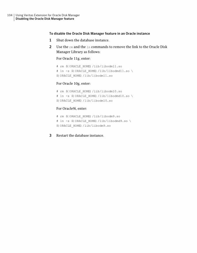
To disable the Oracle Disk Manager feature in an Oracle instance
1 Shut down the database instance.
2 Use the rm and the ln commands to remove the link to the Oracle DiskManager Library as follows:
For Oracle 11g, enter:
# rm ${ORACLE_HOME}/lib/libodm11.so
# ln -s ${ORACLE_HOME}/lib/libodmd11.so \
${ORACLE_HOME}/lib/libodm11.so
For Oracle 10g, enter:
# rm ${ORACLE_HOME}/lib/libodm10.so
# ln -s ${ORACLE_HOME}/lib/libodmd10.so \
${ORACLE_HOME}/lib/libodm10.so
For Oracle9i, enter:
# rm ${ORACLE_HOME}/lib/libodm9.so
# ln -s ${ORACLE_HOME}/lib/libodmd9.so \
${ORACLE_HOME}/lib/libodm9.so
3 Restart the database instance.
Using Veritas Extension for Oracle Disk ManagerDisabling the Oracle Disk Manager feature
104
Veritas Volume Managercluster functionalityadministration
This chapter includes the following topics:
■ About Veritas Volume Manager cluster functionality administration
■ Overview of Cluster Volume Management
About Veritas Volume Manager cluster functionalityadministration
A cluster consists of a number of hosts or nodes that share a set of disks. The mainbenefits of cluster configurations are:
If one node fails, the other nodes can still access the shared disks.When configured with suitable software, mission-critical applicationscan continue running by transferring their execution to a standbynode in the cluster. This ability to provide continuous uninterruptedservice by switching to redundant hardware is commonly termedfailover.
Failover is transparent to users and high-level applications fordatabase and file-sharing. You must configure cluster managementsoftware, such as VCS, to monitor systems and services, and to restartapplications on another node in the event of either hardware orsoftware failure. VCS also allows you to perform generaladministration tasks such as making nodes join or leave a cluster.
Availability
7Chapter
Clusters can reduce contention for system resources by performingactivities such as backup, decision support and report generation onthe more lightly loaded nodes of the cluster. This allows businessesto derive enhanced value from their investment in cluster systems.
Off-hostprocessing
The CVM allows up to 32 nodes in a cluster to simultaneously access and managea set of disks under VxVM control (VM disks). The same logical view of diskconfiguration and any changes to this is available on all the nodes. When thecluster functionality is enabled, all the nodes in the cluster can share VxVM objects.This chapter discusses the cluster functionality that is provided with VxVM.
For complete information on VxVM and CVM. Online versions of the VxVMdocumentation set are installed under the /opt/VRTS/docs directory.
See the Veritas VolumeManager Administrator’s Guide
For complete information on VCS. Online versions of the VCS documentation setare installed under the /opt/VRTS/docs directory.
See the Symantec Cluster Server User’s Guide.
Overview of Cluster Volume ManagementTightly coupled cluster systems have become increasingly popular inenterprise-scale mission-critical data processing. The primary advantage ofclusters is protection against hardware failure. If the primary node fails orotherwise becomes unavailable, applications can continue to run by transferringtheir execution to standby nodes in the cluster. This ability to provide continuousavailability of service by switching to redundant hardware is commonly termedfailover.
Another major advantage of clustered systems is their ability to reduce contentionfor system resources caused by activities such as backup, decision support andreport generation. Enhanced value can be derived from cluster systems byperforming such operations on lightly loaded nodes in the cluster instead of onthe heavily loaded nodes that answer requests for service. This ability to performsome operations on the lightly loaded nodes is commonly termed load balancing.
To implement cluster functionality, VxVM works together with the cluster monitordaemon that is provided by the host operating system or by VCS. The clustermonitor informs VxVM of changes in cluster membership. Each node starts upindependently and has its own cluster monitor plus its own copies of the operatingsystem and VxVM with support for cluster functionality. When a node joins acluster, it gains access to shared disks. When a node leaves a cluster, it no longerhas access to shared disks. A node joins a cluster when the cluster monitor isstarted on that node.
Veritas Volume Manager cluster functionality administrationOverview of Cluster Volume Management
106
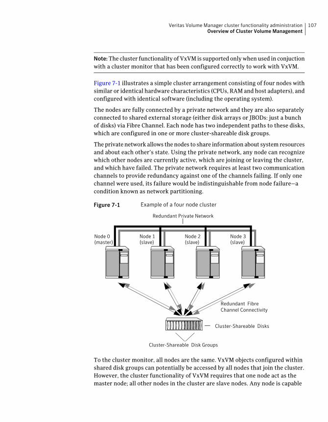
Note:The cluster functionality of VxVM is supported only when used in conjuctionwith a cluster monitor that has been configured correctly to work with VxVM.
Figure 7-1 illustrates a simple cluster arrangement consisting of four nodes withsimilar or identical hardware characteristics (CPUs, RAM and host adapters), andconfigured with identical software (including the operating system).
The nodes are fully connected by a private network and they are also separatelyconnected to shared external storage (either disk arrays or JBODs: just a bunchof disks) via Fibre Channel. Each node has two independent paths to these disks,which are configured in one or more cluster-shareable disk groups.
The private network allows the nodes to share information about system resourcesand about each other’s state. Using the private network, any node can recognizewhich other nodes are currently active, which are joining or leaving the cluster,and which have failed. The private network requires at least two communicationchannels to provide redundancy against one of the channels failing. If only onechannel were used, its failure would be indistinguishable from node failure—acondition known as network partitioning.
Figure 7-1 Example of a four node cluster
Redundant FibreChannel Connectivity
Cluster-Shareable Disks
Redundant Private Network
Node 0(master)
Node 1(slave)
Node 2(slave)
Node 3(slave)
Cluster-Shareable Disk Groups
To the cluster monitor, all nodes are the same. VxVM objects configured withinshared disk groups can potentially be accessed by all nodes that join the cluster.However, the cluster functionality of VxVM requires that one node act as themaster node; all other nodes in the cluster are slave nodes. Any node is capable
107Veritas Volume Manager cluster functionality administrationOverview of Cluster Volume Management
of being the master node, and it is responsible for coordinating certain VxVMactivities.
Note: You must run commands that configure or reconfigure VxVM objects onthe master node. Tasks that must be initiated from the master node include settingup shared disk groups, creating and reconfiguring volumes, and performingsnapshot operations.
VxVM designates the first node to join a cluster performs the function of themaster node. If the master node leaves the cluster, one of the slave nodes is chosento be the new master.
Private and shared disk GroupsThe following types of disk groups are defined:
Belong to only one node. A private disk group is only imported by onesystem. Disks in a private disk group may be physically accessiblefrom one or more systems, but access is restricted to one system only.The boot disk group (usually aliased by the reserved disk group namebootdg) is always a private disk group.
Private diskgroups
Shared by all nodes. A shared (or cluster-shareable) disk group isimported by all cluster nodes. Disks in a shared disk group must bephysically accessible from all systems that may join the cluster.
Shared disk groups
In a cluster, most disk groups are shared. Disks in a shared disk group areaccessible from all nodes in a cluster, allowing applications on multiple clusternodes to simultaneously access the same disk. A volume in a shared disk groupcan be simultaneously accessed by more than one node in the cluster, subject tolicensing and disk group activation mode restrictions.
You can use the vxdg command to designate a disk group as cluster-shareable.
See the Veritas VolumeManager Administrator’s Guide.
When a disk group is imported as cluster-shareable for one node, each disk headeris marked with the cluster ID. As each node subsequently joins the cluster, itrecognizes the disk group as being cluster-shareable and imports it. You can alsoimport or deport a shared disk group at any time; the operation takes places in adistributed fashion on all nodes.
Each physical disk is marked with a unique disk ID. When cluster functionalityfor VxVM starts on the master, it imports all shared disk groups (except for anythat have the noautoimport attribute set). When a slave tries to join a cluster, the
Veritas Volume Manager cluster functionality administrationOverview of Cluster Volume Management
108
master sends it a list of the disk IDs that it has imported, and the slave checks tosee if it can access them all. If the slave cannot access one of the listed disks, itabandons its attempt to join the cluster. If it can access all of the listed disks, itimports the same shared disk groups as the master and joins the cluster. When anode leaves the cluster, it deports all its imported shared disk groups, but theyremain imported on the surviving nodes.
Reconfiguring a shared disk group is performed with the co-operation of all nodes.Configuration changes to the disk group happen simultaneously on all nodes andthe changes are identical. Such changes are atomic in nature, which means thatthey either occur simultaneously on all nodes or not at all.
Whether all members of the cluster have simultaneous read and write access toa cluster-shareable disk group depends on its activation mode setting.
SeeActivating modes of shared disk groups.
The data contained in a cluster-shareable disk group is available as long as at leastone node is active in the cluster. The failure of a cluster node does not affect accessby the remaining active nodes. Regardless of which node accesses acluster-shareable disk group, the configuration of the disk group looks the same.
Note: Applications running on each node can access the data on the VM diskssimultaneously. VxVM does not protect against simultaneous writes to sharedvolumes by more than one node. It is assumed that applications control consistency(by using a distributed lock manager, for example).
Activating modes of shared disk groupsA shared disk group must be activated on a node for the volumes in the disk groupto become accessible for I/O from that node. The ability of applications to readfrom or to write to volumes is determined by the activation mode of a shared diskgroup. Valid activation modes for a shared disk group are exclusive-write,
read-only, shared-read, shared-write, and off (inactive).
Note: The default activation mode for shared disk groups is shared-write.
Applications such as high availability and off-host backup can use disk groupactivation to explicitly control volume access from different nodes in the cluster.
The activation mode of a disk group controls volume I/O from different nodes inthe cluster. It is not possible to activate a disk group on a given node if it isactivated in a conflicting mode on another node in the cluster.
Table 7-1 describes Activation modes for disk groups.
109Veritas Volume Manager cluster functionality administrationOverview of Cluster Volume Management
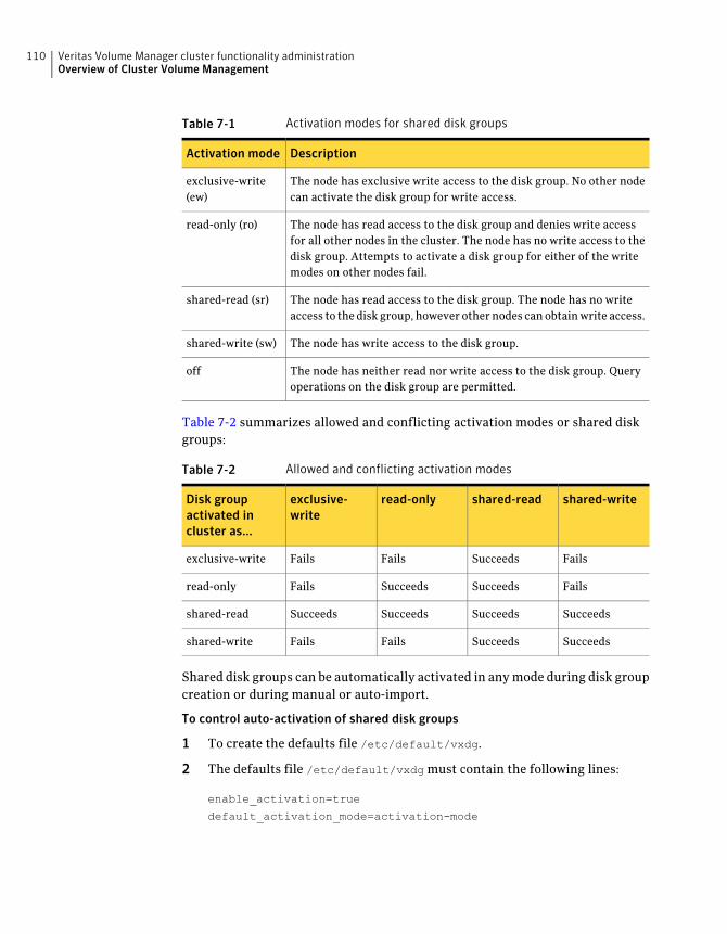
Table 7-1 Activation modes for shared disk groups
DescriptionActivation mode
The node has exclusive write access to the disk group. No other nodecan activate the disk group for write access.
exclusive-write(ew)
The node has read access to the disk group and denies write accessfor all other nodes in the cluster. The node has no write access to thedisk group. Attempts to activate a disk group for either of the writemodes on other nodes fail.
read-only (ro)
The node has read access to the disk group. The node has no writeaccess to the disk group, however other nodes can obtain write access.
shared-read (sr)
The node has write access to the disk group.shared-write (sw)
The node has neither read nor write access to the disk group. Queryoperations on the disk group are permitted.
off
Table 7-2 summarizes allowed and conflicting activation modes or shared diskgroups:
Table 7-2 Allowed and conflicting activation modes
shared-writeshared-readread-onlyexclusive-write
Disk groupactivated incluster as...
FailsSucceedsFailsFailsexclusive-write
FailsSucceedsSucceedsFailsread-only
SucceedsSucceedsSucceedsSucceedsshared-read
SucceedsSucceedsFailsFailsshared-write
Shared disk groups can be automatically activated in any mode during disk groupcreation or during manual or auto-import.
To control auto-activation of shared disk groups
1 To create the defaults file /etc/default/vxdg.
2 The defaults file /etc/default/vxdg must contain the following lines:
enable_activation=true
default_activation_mode=activation-mode
Veritas Volume Manager cluster functionality administrationOverview of Cluster Volume Management
110
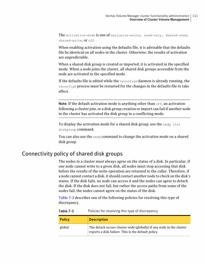
The activation-mode is one of exclusive-write, read-only, shared-read,
shared-write, or off.
When enabling activation using the defaults file, it is advisable that the defaultsfile be identical on all nodes in the cluster. Otherwise, the results of activationare unpredictable.
When a shared disk group is created or imported, it is activated in the specifiedmode. When a node joins the cluster, all shared disk groups accessible from thenode are activated in the specified mode.
If the defaults file is edited while the vxconfigd daemon is already running, thevxconfigd process must be restarted for the changes in the defaults file to takeeffect.
Note: If the default activation mode is anything other than off, an activationfollowing a cluster join, or a disk group creation or import can fail if another nodein the cluster has activated the disk group in a conflicting mode.
To display the activation mode for a shared disk group, use the vxdg list
diskgroup command.
You can also use the vxdg command to change the activation mode on a shareddisk group.
Connectivity policy of shared disk groupsThe nodes in a cluster must always agree on the status of a disk. In particular, ifone node cannot write to a given disk, all nodes must stop accessing that diskbefore the results of the write operation are returned to the caller. Therefore, ifa node cannot contact a disk, it should contact another node to check on the disk’sstatus. If the disk fails, no node can access it and the nodes can agree to detachthe disk. If the disk does not fail, but rather the access paths from some of thenodes fail, the nodes cannot agree on the status of the disk.
Table 7-3 describes one of the following policies for resolving this type ofdiscrepancy.
Table 7-3 Policies for resolving this type of discrepancy
DescriptionPolicy
The detach occurs cluster-wide (globally) if any node in the clusterreports a disk failure. This is the default policy.
global
111Veritas Volume Manager cluster functionality administrationOverview of Cluster Volume Management
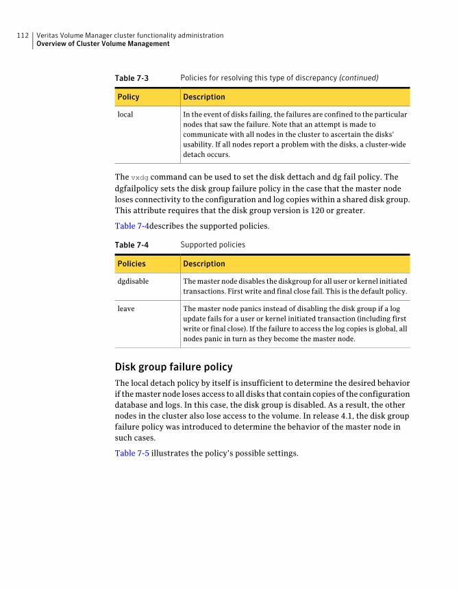
Table 7-3 Policies for resolving this type of discrepancy (continued)
DescriptionPolicy
In the event of disks failing, the failures are confined to the particularnodes that saw the failure. Note that an attempt is made tocommunicate with all nodes in the cluster to ascertain the disks’usability. If all nodes report a problem with the disks, a cluster-widedetach occurs.
local
The vxdg command can be used to set the disk dettach and dg fail policy. Thedgfailpolicy sets the disk group failure policy in the case that the master nodeloses connectivity to the configuration and log copies within a shared disk group.This attribute requires that the disk group version is 120 or greater.
Table 7-4describes the supported policies.
Table 7-4 Supported policies
DescriptionPolicies
The master node disables the diskgroup for all user or kernel initiatedtransactions. First write and final close fail. This is the default policy.
dgdisable
The master node panics instead of disabling the disk group if a logupdate fails for a user or kernel initiated transaction (including firstwrite or final close). If the failure to access the log copies is global, allnodes panic in turn as they become the master node.
leave
Disk group failure policyThe local detach policy by itself is insufficient to determine the desired behaviorif the master node loses access to all disks that contain copies of the configurationdatabase and logs. In this case, the disk group is disabled. As a result, the othernodes in the cluster also lose access to the volume. In release 4.1, the disk groupfailure policy was introduced to determine the behavior of the master node insuch cases.
Table 7-5 illustrates the policy’s possible settings.
Veritas Volume Manager cluster functionality administrationOverview of Cluster Volume Management
112
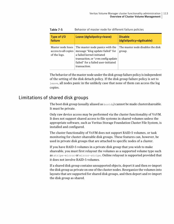
Table 7-5 Behavior of master node for different failure policies
Disable(dgfailpolicy=dgdisable)
Leave (dgfailpolicy=leave)Type of I/Ofailure
The master node disables the diskgroup.
The master node panics with themessage “klog update failed” fora failed kernel-initiatedtransaction, or “cvm config updatefailed” for a failed user-initiatedtransaction.
Master node losesaccess to all copiesof the logs.
The behavior of the master node under the disk group failure policy is independentof the setting of the disk detach policy. If the disk group failure policy is set toleave, all nodes panic in the unlikely case that none of them can access the logcopies.
Limitations of shared disk groupsThe boot disk group (usually aliased as bootdg) cannot be made clustershareable.It must be private.
Only raw device access may be performed via the cluster functionality of VxVM.It does not support shared access to file systems in shared volumes unless theappropriate software, such as Veritas Storage Foundation Cluster File System, isinstalled and configured.
The cluster functionality of VxVM does not support RAID-5 volumes, or taskmonitoring for cluster-shareable disk groups. These features can, however, beused in private disk groups that are attached to specific nodes of a cluster.
If you have RAID-5 volumes in a private disk group that you wish to makeshareable, you must first relayout the volumes as a supported volume type suchas stripe-mirror or mirror-stripe. Online relayout is supported provided thatit does not involve RAID-5 volumes.
If a shared disk group contains unsupported objects, deport it and then re-importthe disk group as private on one of the cluster nodes. Reorganize the volumes intolayouts that are supported for shared disk groups, and then deport and re-importthe disk group as shared.
113Veritas Volume Manager cluster functionality administrationOverview of Cluster Volume Management

Veritas Volume Manager cluster functionality administrationOverview of Cluster Volume Management
114
Agents for StorageFoundation Cluster FileSystem
This chapter includes the following topics:
■ About agents for Storage Foundation Cluster File System
■ Storage Foundation Cluster File System agents
■ Veritas Cluster Server cluster components
■ Modifying the agents and their resources
■ Storage Foundation Cluster File System administrative interface
■ CFSMount agent
■ CFSfsckd agent
■ CVMCluster agent
■ CVMVolDg agent
About agents for Storage Foundation Cluster FileSystem
Agents are processes that manage predefined resource types. When an agent isstarted, it obtains configuration information from the Veritas Cluster Server(VCS). It then periodically monitors the resources and updates VCS with theresource status.
8Chapter
Agents typically do the following:
■ Bring resources online
■ Take resources offline
■ Monitor resources and report any state changes to VCS
VCS bundled agents are part of VCS and are installed when VCS is installed. Thecluster functionality agents are add-on resources to VCS for the Veritas File Systemand Veritas Volume Manager (VxVM). Cluster functionality agents and resourcetypes are part of the VRTScavf package and are configured when you runthecfscluster config command.
See the Symantec Cluster Server Bundled Agents Reference Guide.
PDF versions of this guide are located under the /opt/VRTS/docs directory.
This appendix includes the following topics:
■ Storage Foundation Cluster File System agents
■ Veritas Cluster Server cluster components
■ Modifying the agents and their resources
■ Storage Foundation Cluster File System administrative interface
Storage Foundation Cluster File System agentsSFCFS includes the following agents:
■ CFSMount agent
■ CFSfsckd agent
■ CVMCluster agent
■ CVMVolDg agent
Veritas Cluster Server cluster componentsResources, attributes, and service groups are components integral to clusterfunctionality.
See the Symantec Cluster Server User’s Guide.
ResourcesResources are hardware or software entities, such as disks, volumes, file systemmount points, network interface cards (NICs), IP addresses, applications, and
Agents for Storage Foundation Cluster File SystemStorage Foundation Cluster File System agents
116
databases. Resources work together to provide a service to clients in a client/serverenvironment. Resource types are defined in the types.cf file by a collection ofattributes. The VCS configuration file, main.cf, contains the values for theattributes of the resources. The main.cf file incorporates the resources listed inthe types.cf by way of an include directive.
AttributesAttributes contain data regarding the cluster, nodes, service groups, resources,resource types, and agents. A specified value for a given attribute configures theresource to function in a specific way. By modifying the value of an attribute ofa resource, you change the way the VCS agent manages the resource. Each attributehas a definition and a value. You define an attribute by specifying its data typeand dimension. Attributes also have default values that are assigned when a valueis not specified.
Service groupsService groups are comprised of related resources. When a service group is broughtonline, all the resources within the group are brought online.
Modifying the agents and their resourcesYou can use the VCS Cluster Manager GUI, or enter VCS commands (the “ha”commands such as hastatus and haconf) from the command line, to modify theconfiguration of the resources managed by an agent. You can also edit the main.cffile directly, but you must reboot your system for the changes to take effect. Anexample main.cf file is located in the /etc/VRTSvcs/conf/sample_cvm directory.
It is advisable to use the Veritas Cluster Server GUI to administer your clusterfile system resources.
See Veritas Cluster Server Installation Guide.
Resources and service groups for File System cluster functionalityManaging cluster mounts through VCS requires various resources types, resources,and service groups.
The following VCS resource types required for Veritas Volume Manager clusterfunctionality (or CVM) are:
■ CVMCluster
■ CVMVolDg
117Agents for Storage Foundation Cluster File SystemModifying the agents and their resources
CVMCluster controls the overall operation of CVM. The agents of CVMClusterbring up the CVM cluster. Only one CVMCluster resource is required in a VCSenvironment. It is advisable to use the standard configuration procedure for CVMto add the CVMCluster resource. The procedure creates a service group namedcvm and adds the resources to the configuration.
See “Storage Foundation Cluster File System administrative interface” on page 119.
The following VCS resource types required for SFCFS functionality are:
■ CFSfsckd
■ CFSMount
CFSfsckd is a mandatory resource type for SFCFS functionality. CFSfsckd agentsstart the cluster file system check (fsck command) daemon, vxfsckd, which mustbe running for a cluster mount to succeed. As with CVMCluster, only one resourceinstance is required for CFSfsckd. You add these resources using the SFCFSconfiguration process, which adds the resources to the cvm service group.
See “The cfscluster command” on page 119.
Each CVMVolDg resource controls one shared disk group, and one or more sharedvolumes of that disk group. CVMVolDg resources enable the disk group and setthe disk group activation mode. Each CFSMount resource controls the clustermount of a shared volume on a specified mount point. CFSMount resources alsokeep track of mount options associated with the mount points.
These resource instances are not added automatically during the SFCFSconfiguration; you must add them as required using the SFCFS clusteradministration commands.
Note: That the CFSMount and CVMVolDg resources are not added to the cvm
service group; those should be added to a different service group.
See “The cfsmntadm command” on page 120.
Resource and service group dependenciesDependencies between resources and service groups specify the order in whichthe resource and service group are brought online and taken offline, which mustbe done in correct sequence.
The various resources and service groups required for SFCFS must follow thesedependency (or link) rules:
■ A CFSMount resource must depend on the corresponding CVMVolDg resource
Agents for Storage Foundation Cluster File SystemModifying the agents and their resources
118
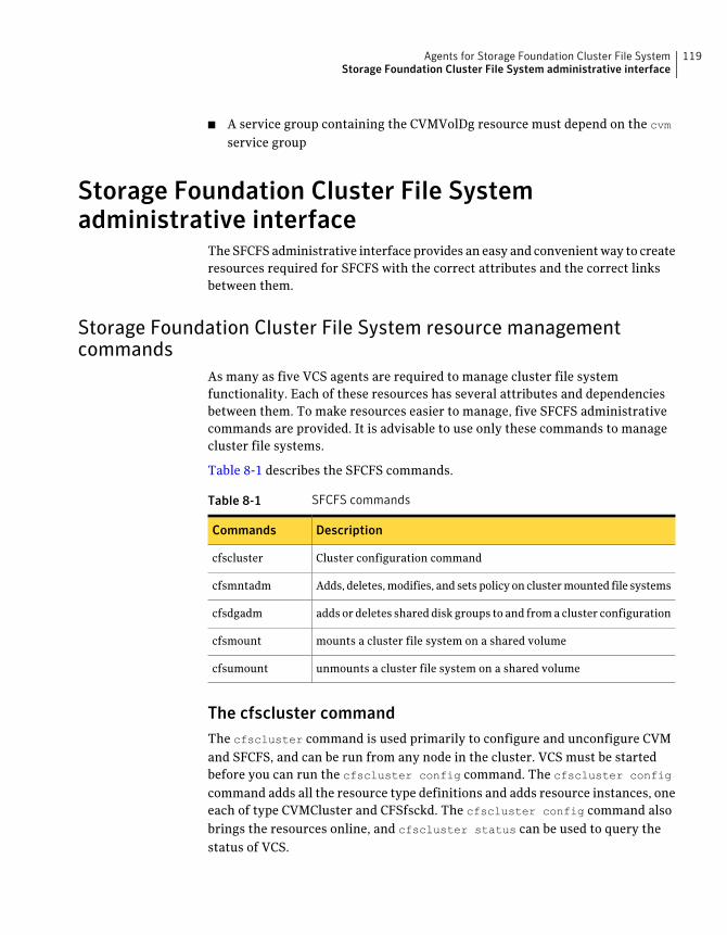
■ A service group containing the CVMVolDg resource must depend on the cvm
service group
Storage Foundation Cluster File Systemadministrative interface
The SFCFS administrative interface provides an easy and convenient way to createresources required for SFCFS with the correct attributes and the correct linksbetween them.
Storage Foundation Cluster File System resource managementcommands
As many as five VCS agents are required to manage cluster file systemfunctionality. Each of these resources has several attributes and dependenciesbetween them. To make resources easier to manage, five SFCFS administrativecommands are provided. It is advisable to use only these commands to managecluster file systems.
Table 8-1 describes the SFCFS commands.
Table 8-1 SFCFS commands
DescriptionCommands
Cluster configuration commandcfscluster
Adds, deletes, modifies, and sets policy on cluster mounted file systemscfsmntadm
adds or deletes shared disk groups to and from a cluster configurationcfsdgadm
mounts a cluster file system on a shared volumecfsmount
unmounts a cluster file system on a shared volumecfsumount
The cfscluster commandThe cfscluster command is used primarily to configure and unconfigure CVMand SFCFS, and can be run from any node in the cluster. VCS must be startedbefore you can run the cfscluster config command. The cfscluster config
command adds all the resource type definitions and adds resource instances, oneeach of type CVMCluster and CFSfsckd. The cfscluster config command alsobrings the resources online, and cfscluster status can be used to query thestatus of VCS.
119Agents for Storage Foundation Cluster File SystemStorage Foundation Cluster File System administrative interface
See “Resources and service groups for File System cluster functionality”on page 117.
The cfscluster unconfig command takes resources offline (except CFSMountresources) and removes all the resources and service groups that were used tomanage the cluster file system.
See the cfscluster(1M) manual page.
You must manually take CFSMount resources offline (using the cfsumount
command) before executing the cfscluster unconfig command.
The cfsmntadm commandOne CVMVolDg and one CFSMount resource is required to control each clustermount. You can use the cfsmntadm add to add these resources. The cfsmntadm
command takes mount points, shared volumes, and shared disk groups asarguments. You can optionally specify a service group name. If a service groupname is specified, the cfsmntadm command creates a new service group (if theservice group is not already present) and makes it dependent on the cvm servicegroup. If no service group name is specified, cfsmntadm add creates a defaultservice group, cfs. The command next adds CVMVolDg to the specified servicegroup and associates it with the specified disk group (if that kind of resource isnot already present in the same service group). Subsequently, cfsmntadm add
adds a CFSMount resource and links it with the CVMVolDg resource, then setsthe appropriate values to the resource attributes. It is advisable to add all themount points (that have their device in the same shared disk group) to the sameservice group.
See “Resources and service groups for File System cluster functionality”on page 117.
Using cfsmntadm, you can also add file system snapshots and Storage Checkpoints;delete, display, and modify resources; and set the primary election policy on acluster mounted file system.
See the cfsmntadm(1M) manual page.
The cfsdgadm commandThe cfsdgadm command is the administrative interface for shared disk groups.Using cfsdgadm, you can add a shared disk group to a cluster configuration, deletea shared disk group, modify the activation mode, or display the shared disk group’sconfiguration information. A shared disk group must already exist before beingspecified with cfsdgadm command.
See the cfsdgadm(1M) manual page.
Agents for Storage Foundation Cluster File SystemStorage Foundation Cluster File System administrative interface
120
The cfsmount and cfsumount commandThe cfsmount command mounts a cluster file system on a shared volume on oneor more nodes. If no nodes are specified, the cluster file system is mounted on allassociated nodes in the cluster. The cluster mount instance for the shared volumemust be previously defined by the cfsmntadm add command before runningcfsmount. The cfsumount command unmounts one or more shared volumes
See the cfsmount(1M) manual page.
Figure 8-1 describes the SFCFS service groups and resource dependencies.
121Agents for Storage Foundation Cluster File SystemStorage Foundation Cluster File System administrative interface
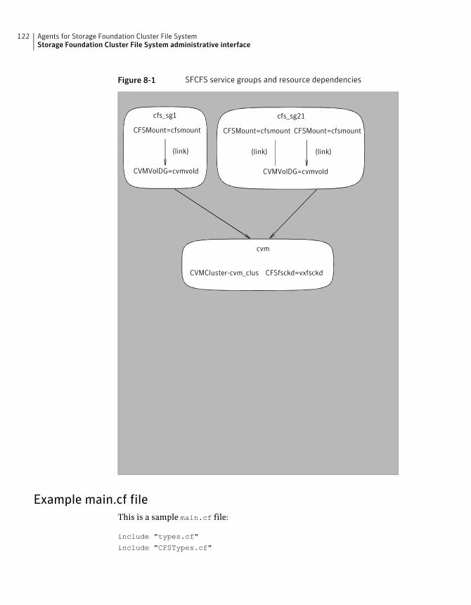
Figure 8-1 SFCFS service groups and resource dependencies
CVMVolDG=cvmvold
cfs_sg1
CFSMount=cfsmount
(link)
cvm
CVMCluster-cvm_clus CFSfsckd=vxfsckd
CVMVolDG=cvmvold
cfs_sg21
CFSMount=cfsmount
(link)
CFSMount=cfsmount
(link)
Example main.cf fileThis is a sample main.cf file:
include "types.cf"
include "CFSTypes.cf"
Agents for Storage Foundation Cluster File SystemStorage Foundation Cluster File System administrative interface
122
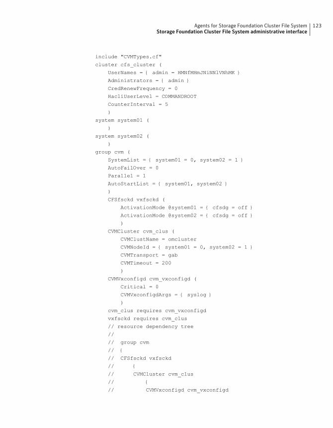
include "CVMTypes.cf"
cluster cfs_cluster (
UserNames = { admin = HMNfMHmJNiNNlVNhMK }
Administrators = { admin }
CredRenewFrequency = 0
HacliUserLevel = COMMANDROOT
CounterInterval = 5
)
system system01 (
)
system system02 (
)
group cvm (
SystemList = { system01 = 0, system02 = 1 }
AutoFailOver = 0
Parallel = 1
AutoStartList = { system01, system02 }
)
CFSfsckd vxfsckd (
ActivationMode @system01 = { cfsdg = off }
ActivationMode @system02 = { cfsdg = off }
)
CVMCluster cvm_clus (
CVMClustName = omcluster
CVMNodeId = { system01 = 0, system02 = 1 }
CVMTransport = gab
CVMTimeout = 200
)
CVMVxconfigd cvm_vxconfigd (
Critical = 0
CVMVxconfigdArgs = { syslog }
)
cvm_clus requires cvm_vxconfigd
vxfsckd requires cvm_clus
// resource dependency tree
//
// group cvm
// {
// CFSfsckd vxfsckd
// {
// CVMCluster cvm_clus
// {
// CVMVxconfigd cvm_vxconfigd
123Agents for Storage Foundation Cluster File SystemStorage Foundation Cluster File System administrative interface
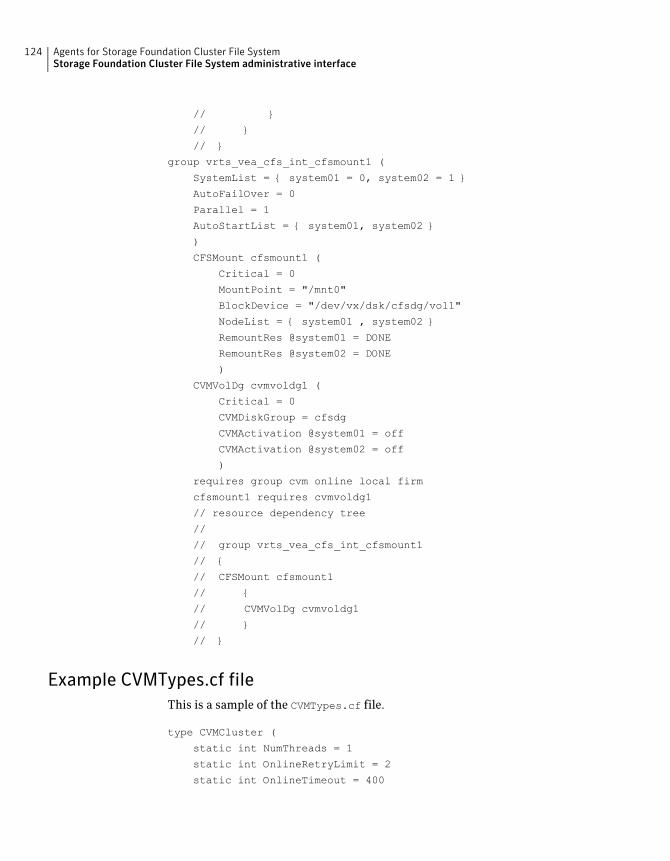
// }
// }
// }
group vrts_vea_cfs_int_cfsmount1 (
SystemList = { system01 = 0, system02 = 1 }
AutoFailOver = 0
Parallel = 1
AutoStartList = { system01, system02 }
)
CFSMount cfsmount1 (
Critical = 0
MountPoint = "/mnt0"
BlockDevice = "/dev/vx/dsk/cfsdg/vol1"
NodeList = { system01 , system02 }
RemountRes @system01 = DONE
RemountRes @system02 = DONE
)
CVMVolDg cvmvoldg1 (
Critical = 0
CVMDiskGroup = cfsdg
CVMActivation @system01 = off
CVMActivation @system02 = off
)
requires group cvm online local firm
cfsmount1 requires cvmvoldg1
// resource dependency tree
//
// group vrts_vea_cfs_int_cfsmount1
// {
// CFSMount cfsmount1
// {
// CVMVolDg cvmvoldg1
// }
// }
Example CVMTypes.cf fileThis is a sample of the CVMTypes.cf file.
type CVMCluster (
static int NumThreads = 1
static int OnlineRetryLimit = 2
static int OnlineTimeout = 400
Agents for Storage Foundation Cluster File SystemStorage Foundation Cluster File System administrative interface
124
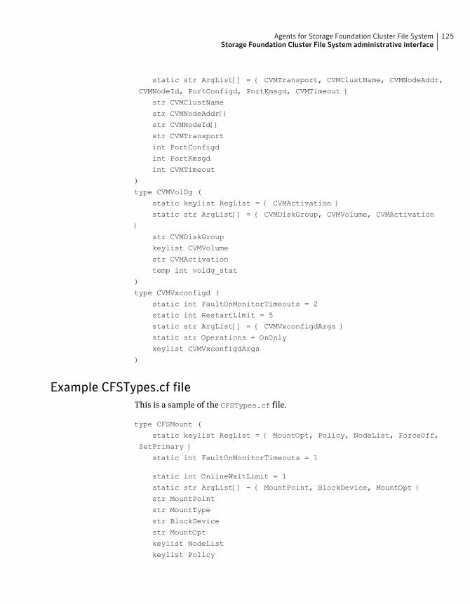
static str ArgList[] = { CVMTransport, CVMClustName, CVMNodeAddr,
CVMNodeId, PortConfigd, PortKmsgd, CVMTimeout }
str CVMClustName
str CVMNodeAddr{}
str CVMNodeId{}
str CVMTransport
int PortConfigd
int PortKmsgd
int CVMTimeout
)
type CVMVolDg (
static keylist RegList = { CVMActivation }
static str ArgList[] = { CVMDiskGroup, CVMVolume, CVMActivation
}
str CVMDiskGroup
keylist CVMVolume
str CVMActivation
temp int voldg_stat
)
type CVMVxconfigd (
static int FaultOnMonitorTimeouts = 2
static int RestartLimit = 5
static str ArgList[] = { CVMVxconfigdArgs }
static str Operations = OnOnly
keylist CVMVxconfigdArgs
)
Example CFSTypes.cf fileThis is a sample of the CFSTypes.cf file.
type CFSMount (
static keylist RegList = { MountOpt, Policy, NodeList, ForceOff,
SetPrimary }
static int FaultOnMonitorTimeouts = 1
static int OnlineWaitLimit = 1
static str ArgList[] = { MountPoint, BlockDevice, MountOpt }
str MountPoint
str MountType
str BlockDevice
str MountOpt
keylist NodeList
keylist Policy
125Agents for Storage Foundation Cluster File SystemStorage Foundation Cluster File System administrative interface
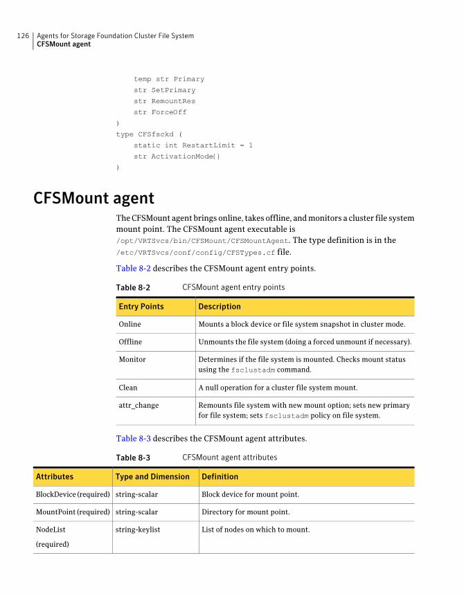
temp str Primary
str SetPrimary
str RemountRes
str ForceOff
)
type CFSfsckd (
static int RestartLimit = 1
str ActivationMode{}
)
CFSMount agentThe CFSMount agent brings online, takes offline, and monitors a cluster file systemmount point. The CFSMount agent executable is/opt/VRTSvcs/bin/CFSMount/CFSMountAgent. The type definition is in the/etc/VRTSvcs/conf/config/CFSTypes.cf file.
Table 8-2 describes the CFSMount agent entry points.
Table 8-2 CFSMount agent entry points
DescriptionEntry Points
Mounts a block device or file system snapshot in cluster mode.Online
Unmounts the file system (doing a forced unmount if necessary).Offline
Determines if the file system is mounted. Checks mount statususing the fsclustadm command.
Monitor
A null operation for a cluster file system mount.Clean
Remounts file system with new mount option; sets new primaryfor file system; sets fsclustadm policy on file system.
attr_change
Table 8-3 describes the CFSMount agent attributes.
Table 8-3 CFSMount agent attributes
DefinitionType and DimensionAttributes
Block device for mount point.string-scalarBlockDevice (required)
Directory for mount point.string-scalarMountPoint (required)
List of nodes on which to mount.string-keylistNodeList
(required)
Agents for Storage Foundation Cluster File SystemCFSMount agent
126
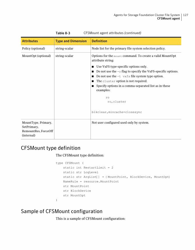
Table 8-3 CFSMount agent attributes (continued)
DefinitionType and DimensionAttributes
Node list for the primary file system selection policy.string-scalarPolicy (optional)
Options for the mount command. To create a valid MountOptattribute string:
■ Use VxFS type-specific options only.
■ Do not use the -o flag to specify the VxFS-specific options.
■ Do not use the -t vxfs file system type option.
■ The cluster option is not required.
■ Specify options in a comma-separated list as in theseexamples:
roro,cluster
blkclear,mincache=closesync
string-scalarMountOpt (optional)
Not user configured used only by system.MountType, Primary,SetPrimary,RemountRes, ForceOff(internal)
CFSMount type definitionThe CFSMount type definition:
type CFSMount (
static int RestartLimit = 2
static str LogLevel
static str ArgList[] = {MountPoint, BlockDevice, MountOpt}
NameRule = resource.MountPoint
str MountPoint
str BlockDevice
str MountOpt
)
Sample of CFSMount configurationThis is a sample of CFSMount configuration:
127Agents for Storage Foundation Cluster File SystemCFSMount agent
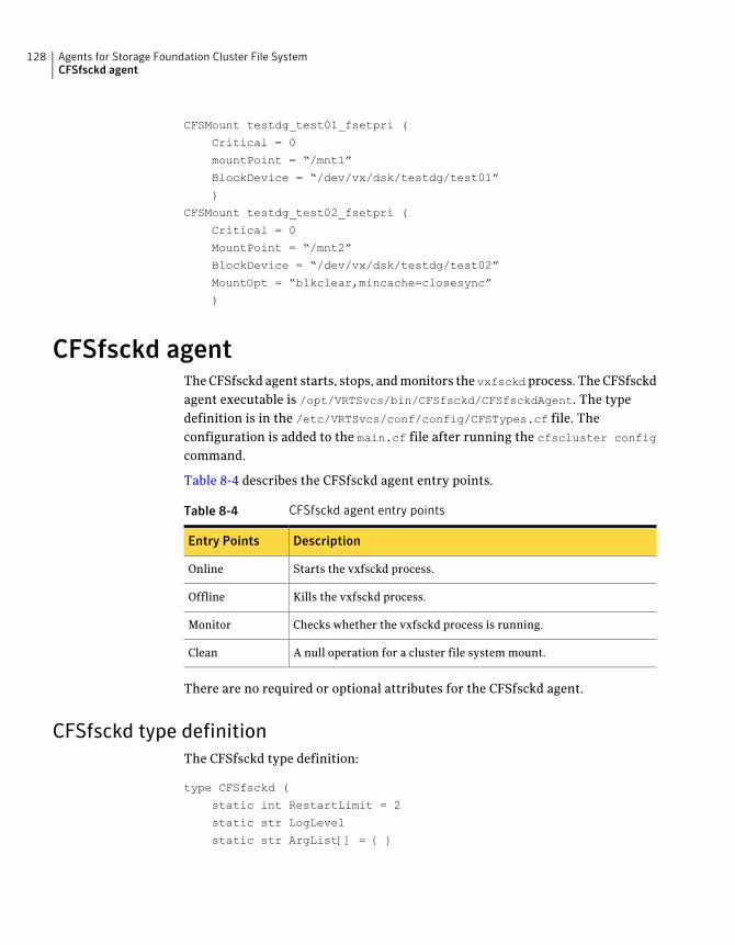
CFSMount testdg_test01_fsetpri (
Critical = 0
mountPoint = “/mnt1”
BlockDevice = “/dev/vx/dsk/testdg/test01”
)
CFSMount testdg_test02_fsetpri (
Critical = 0
MountPoint = “/mnt2”
BlockDevice = “/dev/vx/dsk/testdg/test02”
MountOpt = “blkclear,mincache=closesync”
)
CFSfsckd agentThe CFSfsckd agent starts, stops, and monitors the vxfsckdprocess. The CFSfsckdagent executable is /opt/VRTSvcs/bin/CFSfsckd/CFSfsckdAgent. The typedefinition is in the /etc/VRTSvcs/conf/config/CFSTypes.cf file. Theconfiguration is added to the main.cf file after running the cfscluster config
command.
Table 8-4 describes the CFSfsckd agent entry points.
Table 8-4 CFSfsckd agent entry points
DescriptionEntry Points
Starts the vxfsckd process.Online
Kills the vxfsckd process.Offline
Checks whether the vxfsckd process is running.Monitor
A null operation for a cluster file system mount.Clean
There are no required or optional attributes for the CFSfsckd agent.
CFSfsckd type definitionThe CFSfsckd type definition:
type CFSfsckd (
static int RestartLimit = 2
static str LogLevel
static str ArgList[] = { }
Agents for Storage Foundation Cluster File SystemCFSfsckd agent
128
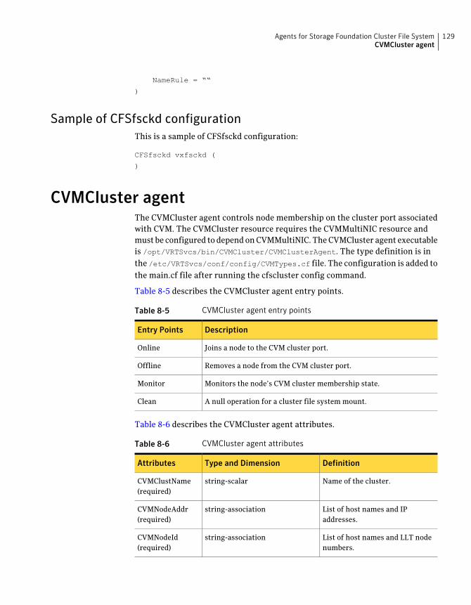
NameRule = ““
)
Sample of CFSfsckd configurationThis is a sample of CFSfsckd configuration:
CFSfsckd vxfsckd (
)
CVMCluster agentThe CVMCluster agent controls node membership on the cluster port associatedwith CVM. The CVMCluster resource requires the CVMMultiNIC resource andmust be configured to depend on CVMMultiNIC. The CVMCluster agent executableis /opt/VRTSvcs/bin/CVMCluster/CVMClusterAgent. The type definition is inthe /etc/VRTSvcs/conf/config/CVMTypes.cf file. The configuration is added tothe main.cf file after running the cfscluster config command.
Table 8-5 describes the CVMCluster agent entry points.
Table 8-5 CVMCluster agent entry points
DescriptionEntry Points
Joins a node to the CVM cluster port.Online
Removes a node from the CVM cluster port.Offline
Monitors the node’s CVM cluster membership state.Monitor
A null operation for a cluster file system mount.Clean
Table 8-6 describes the CVMCluster agent attributes.
Table 8-6 CVMCluster agent attributes
DefinitionType and DimensionAttributes
Name of the cluster.string-scalarCVMClustName(required)
List of host names and IPaddresses.
string-associationCVMNodeAddr(required)
List of host names and LLT nodenumbers.
string-associationCVMNodeId(required)
129Agents for Storage Foundation Cluster File SystemCVMCluster agent
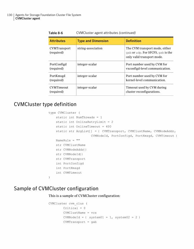
Table 8-6 CVMCluster agent attributes (continued)
DefinitionType and DimensionAttributes
The CVM transport mode, eithergab or udp. For SFCFS, gab is theonly valid transport mode.
string-associationCVMTransport(required)
Port number used by CVM forvxconfigd-level communication.
integer-scalarPortConfigd(required)
Port number used by CVM forkernel-level communication.
integer-scalarPortKmsgd(required)
Timeout used by CVM duringcluster reconfigurations.
integer-scalarCVMTimeout(required)
CVMCluster type definitiontype CVMCluster (
static int NumThreads = 1
static int OnlineRetryLimit = 2
static int OnlineTimeout = 400
static str ArgList[] = { CVMTransport, CVMClustName, CVMNodeAddr,
CVMNodeId, PortConfigd, PortKmsgd, CVMTimeout }
NameRule = ""
str CVMClustName
str CVMNodeAddr{}
str CVMNodeId{}
str CVMTransport
int PortConfigd
int PortKmsgd
int CVMTimeout
)
Sample of CVMCluster configurationThis is a sample of CVMCluster configuration:
CVMCluster cvm_clus (
Critical = 0
CVMClustName = vcs
CVMNodeId = { system01 = 1, system02 = 2 }
CVMTransport = gab
Agents for Storage Foundation Cluster File SystemCVMCluster agent
130
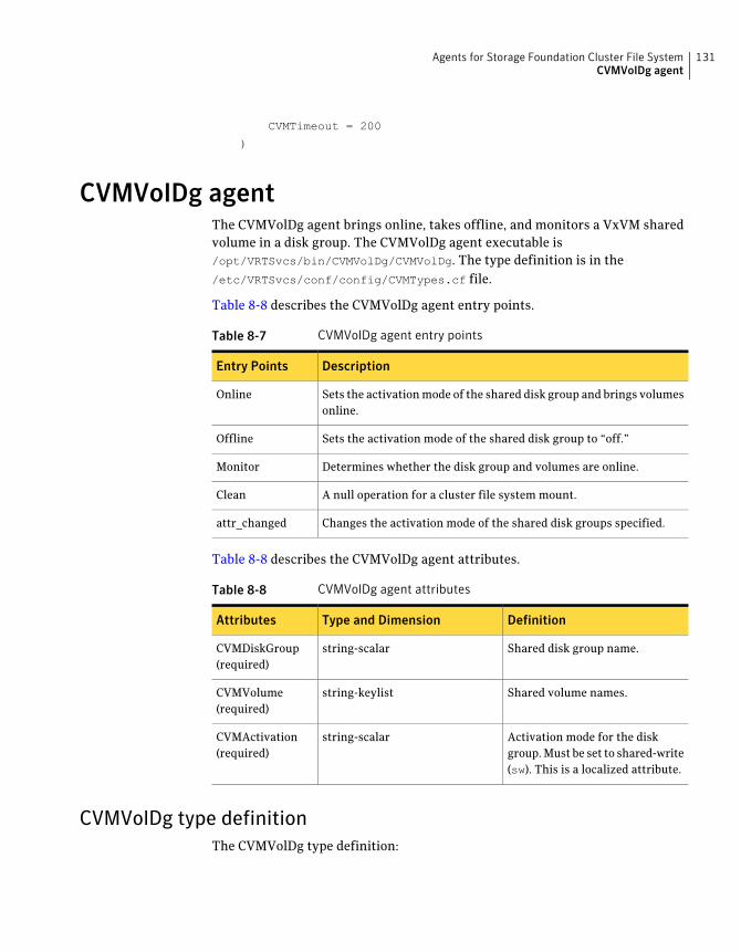
CVMTimeout = 200
)
CVMVolDg agentThe CVMVolDg agent brings online, takes offline, and monitors a VxVM sharedvolume in a disk group. The CVMVolDg agent executable is/opt/VRTSvcs/bin/CVMVolDg/CVMVolDg. The type definition is in the/etc/VRTSvcs/conf/config/CVMTypes.cf file.
Table 8-8 describes the CVMVolDg agent entry points.
Table 8-7 CVMVolDg agent entry points
DescriptionEntry Points
Sets the activation mode of the shared disk group and brings volumesonline.
Online
Sets the activation mode of the shared disk group to “off.”Offline
Determines whether the disk group and volumes are online.Monitor
A null operation for a cluster file system mount.Clean
Changes the activation mode of the shared disk groups specified.attr_changed
Table 8-8 describes the CVMVolDg agent attributes.
Table 8-8 CVMVolDg agent attributes
DefinitionType and DimensionAttributes
Shared disk group name.string-scalarCVMDiskGroup(required)
Shared volume names.string-keylistCVMVolume(required)
Activation mode for the diskgroup. Must be set to shared-write(sw). This is a localized attribute.
string-scalarCVMActivation(required)
CVMVolDg type definitionThe CVMVolDg type definition:
131Agents for Storage Foundation Cluster File SystemCVMVolDg agent
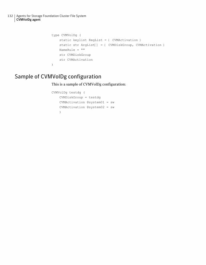
type CVMVolDg (
static keylist RegList = { CVMActivation }
static str ArgList[] = { CVMDiskGroup, CVMActivation }
NameRule = ""
str CVMDiskGroup
str CVMActivation
)
Sample of CVMVolDg configurationThis is a sample of CVMVolDg configuration:
CVMVolDg testdg (
CVMDiskGroup = testdg
CVMActivation @system01 = sw
CVMActivation @system02 = sw
)
Agents for Storage Foundation Cluster File SystemCVMVolDg agent
132
Creating a starter database
This appendix includes the following topics:
■ Creating a database for Oracle 10g or 11g
Creating a database for Oracle 10g or 11gCreate a database tablespace for Oracle 10g or 11g using one of the two options:
■ Option 1: on shared raw VxVM volumes
■ Option 2: on cluster file system (CFS)
Before you begin, take note of the following prerequisites:
■ CRS daemons must be running. To verify the status of CRS, enter:
# $CRS_HOME/bin/crs_stat
■ Use the ping command to verify that all private IP addresses on each node areup.
Creating database tablespace on shared raw VxVM volumes (option1)
This section describes how to create database tablespace on shared raw VxVMvolumes (option 1).
AAppendix
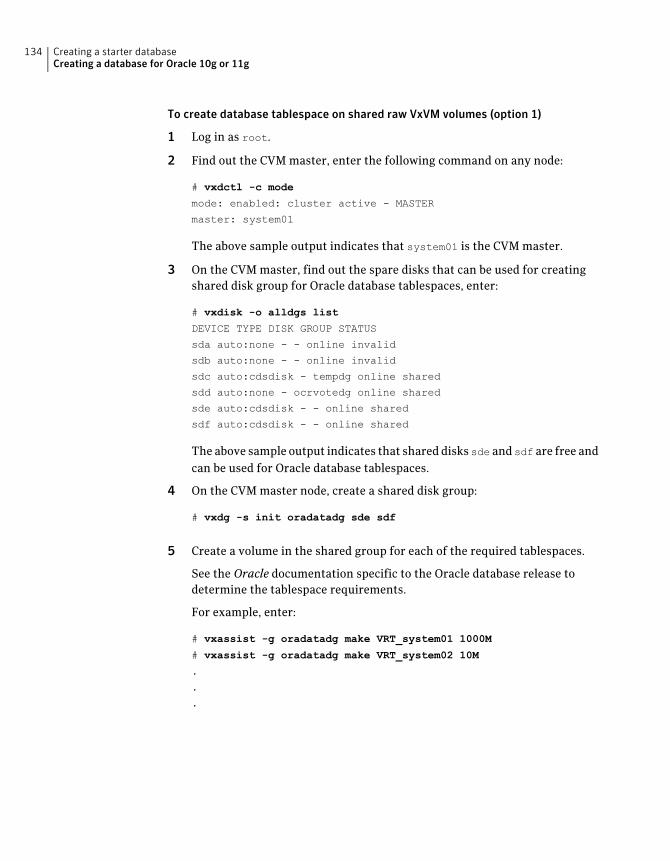
To create database tablespace on shared raw VxVM volumes (option 1)
1 Log in as root.
2 Find out the CVM master, enter the following command on any node:
# vxdctl -c mode
mode: enabled: cluster active - MASTER
master: system01
The above sample output indicates that system01 is the CVM master.
3 On the CVM master, find out the spare disks that can be used for creatingshared disk group for Oracle database tablespaces, enter:
# vxdisk -o alldgs list
DEVICE TYPE DISK GROUP STATUS
sda auto:none - - online invalid
sdb auto:none - - online invalid
sdc auto:cdsdisk - tempdg online shared
sdd auto:none - ocrvotedg online shared
sde auto:cdsdisk - - online shared
sdf auto:cdsdisk - - online shared
The above sample output indicates that shared disks sde and sdf are free andcan be used for Oracle database tablespaces.
4 On the CVM master node, create a shared disk group:
# vxdg -s init oradatadg sde sdf
5 Create a volume in the shared group for each of the required tablespaces.
See the Oracle documentation specific to the Oracle database release todetermine the tablespace requirements.
For example, enter:
# vxassist -g oradatadg make VRT_system01 1000M
# vxassist -g oradatadg make VRT_system02 10M
.
.
.
Creating a starter databaseCreating a database for Oracle 10g or 11g
134
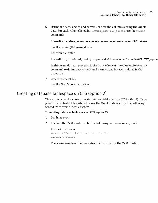
6 Define the access mode and permissions for the volumes storing the Oracledata. For each volume listed in $ORACLE_HOME/raw_config, use the vxedit
command:
# vxedit -g disk_group set group=group user=user mode=660 volume
See the vxedit(1M) manual page.
For example, enter:
# vxedit -g oradatadg set group=oinstall user=oracle mode=660 VRT_system01
In this example, VRT_system01 is the name of one of the volumes. Repeat thecommand to define access mode and permissions for each volume in theoradatadg.
7 Create the database.
See the Oracle documentation.
Creating database tablespace on CFS (option 2)This section describes how to create database tablespace on CFS (option 2). If youplan to use a cluster file system to store the Oracle database, use the followingprocedure to create the file system.
To creating database tablespace on CFS (option 2)
1 Log in as root.
2 Find out the CVM master, enter the following command on any node:
# vxdctl -c mode
mode: enabled: cluster active - MASTER
master: system01
The above sample output indicates that system01 is the CVM master.
135Creating a starter databaseCreating a database for Oracle 10g or 11g
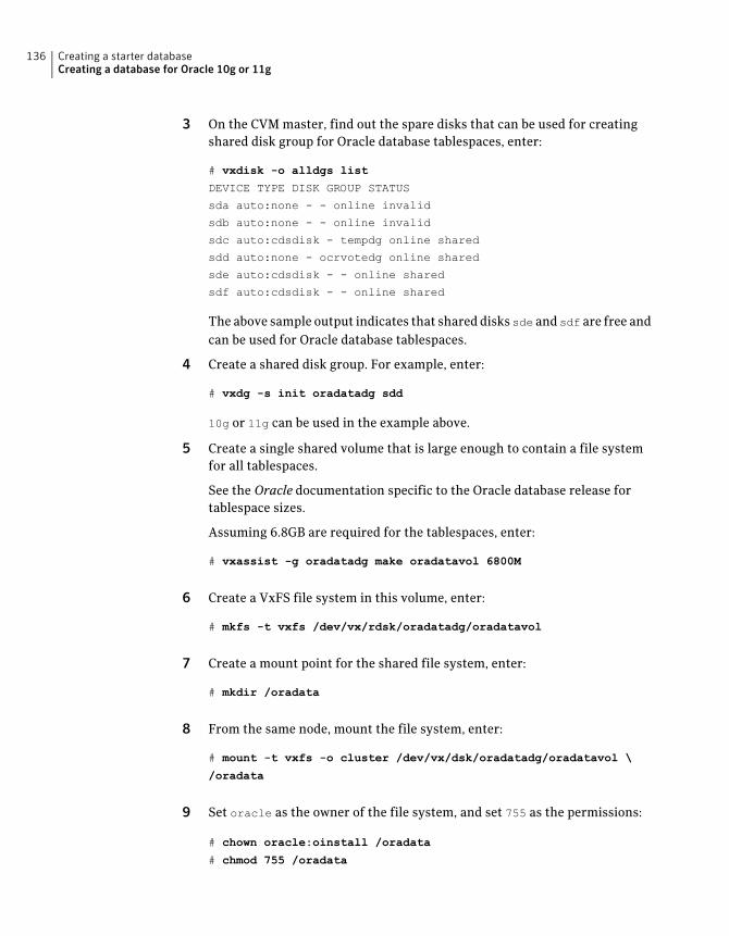
3 On the CVM master, find out the spare disks that can be used for creatingshared disk group for Oracle database tablespaces, enter:
# vxdisk -o alldgs list
DEVICE TYPE DISK GROUP STATUS
sda auto:none - - online invalid
sdb auto:none - - online invalid
sdc auto:cdsdisk - tempdg online shared
sdd auto:none - ocrvotedg online shared
sde auto:cdsdisk - - online shared
sdf auto:cdsdisk - - online shared
The above sample output indicates that shared disks sde and sdf are free andcan be used for Oracle database tablespaces.
4 Create a shared disk group. For example, enter:
# vxdg -s init oradatadg sdd
10g or 11g can be used in the example above.
5 Create a single shared volume that is large enough to contain a file systemfor all tablespaces.
See the Oracle documentation specific to the Oracle database release fortablespace sizes.
Assuming 6.8GB are required for the tablespaces, enter:
# vxassist -g oradatadg make oradatavol 6800M
6 Create a VxFS file system in this volume, enter:
# mkfs -t vxfs /dev/vx/rdsk/oradatadg/oradatavol
7 Create a mount point for the shared file system, enter:
# mkdir /oradata
8 From the same node, mount the file system, enter:
# mount -t vxfs -o cluster /dev/vx/dsk/oradatadg/oradatavol \
/oradata
9 Set oracle as the owner of the file system, and set 755 as the permissions:
# chown oracle:oinstall /oradata
# chmod 755 /oradata
Creating a starter databaseCreating a database for Oracle 10g or 11g
136

10 On the other node(s), complete steps 7 through 9.
11 Create the Oracle database.
See the Oracle documentation.
137Creating a starter databaseCreating a database for Oracle 10g or 11g

Creating a starter databaseCreating a database for Oracle 10g or 11g
138
access control list (ACL) The information that identifies specific users or groups and their access privilegesfor a particular file or directory.
agent A process that manages predefined Veritas Cluster Server (VCS) resource types.Agents bring resources online, take resources offline, and monitor resources toreport any state changes to VCS. When an agent is started, it obtains configurationinformation from VCS and periodically monitors the resources and updates VCSwith the resource status.
allocation unit A group of consecutive blocks on a file system that contain resource summaries,free resource maps, and data blocks. Allocation units also contain copies of thesuper-block.
API Application Programming Interface.
asynchronous writes A delayed write in which the data is written to a page in the system’s page cache,but is not written to disk before the write returns to the caller. This improvesperformance, but carries the risk of data loss if the system crashes before the datais flushed to disk.
atomic operation An operation that either succeeds completely or fails and leaves everything as itwas before the operation was started. If the operation succeeds, all aspects of theoperation take effect at once and the intermediate states of change are invisible.If any aspect of the operation fails, then the operation aborts without leavingpartial changes.
Block-Level Incremental
Backup (BLI Backup)
A Veritas backup capability that does not store and retrieve entire files. Instead,only the data blocks that have changed since the previous backup are backed up.
boot disk A disk that is used for the purpose of booting a system.
boot disk group A private disk group that contains the disks from which the system may be booted.
buffered I/O A mode of I/O operation (where I/O is any operation, program, or device thattransfers data to or from a computer) that first transfers data into the OperatingSystem buffer cache.
bootdg A reserved disk group name that is an alias for the name of the boot disk group.
cluster mounted file
system
A shared file system that enables multiple hosts to mount and perform fileoperations on the same file. A cluster mount requires a shared storage device thatcan be accessed by other cluster mounts of the same file system. Writes to the
Glossary
shared device can be done concurrently from any host on which the cluster filesystem is mounted. To be a cluster mount, a file system must be mounted usingthe mount -o cluster option.
Cluster Services The group atomic broadcast (GAB) module in the SFCFS stack provides clustermembership services to the file system. LLT provides kernel-to-kernelcommunications and monitors network communications.
contiguous file A file in which data blocks are physically adjacent on the underlying media.
CVM The cluster functionality of Veritas Volume Manager.
CVM Master The cluster volume manager (CVM) has a master node that records changes tothe volume configuration.
data block A block that contains the actual data belonging to files and directories.
data synchronous
writes
A form of synchronous I/O that writes the file data to disk before the write returns,but only marks the inode for later update. If the file size changes, the inode willbe written before the write returns. In this mode, the file data is guaranteed to beon the disk before the write returns, but the inode modification times may be lostif the system crashes.
defragmentation The process of reorganizing data on disk by making file data blocks physicallyadjacent to reduce access times.
direct extent An extent that is referenced directly by an inode.
direct I/O An unbuffered form of I/O that bypasses the kernel’s buffering of data. With directI/O, the file system transfers data directly between the disk and the user-suppliedbuffer.
discovered direct I/O Discovered Direct I/O behavior is similar to direct I/O and has the same alignmentconstraints, except writes that allocate storage or extend the file size do not requirewriting the inode changes before returning to the application.
encapsulation A process that converts existing partitions on a specified disk to volumes. If anypartitions contain file systems, /etc/fstab entries are modified so that the filesystems are mounted on volumes instead. Encapsulation is not applicable on somesystems.
extent A group of contiguous file system data blocks treated as a single unit. An extentis defined by the address of the starting block and a length.
extent attribute A policy that determines how a file allocates extents.
external quotas file A quotas file (named quotas) must exist in the root directory of a file system forquota-related commands to work. Support for group quotas requires a groupquotas file is named quotas.grp.
Glossary140
file system block The fundamental minimum size of allocation in a file system. This is equivalentto the fragment size on some UNIX file systems.
fileset A collection of files within a file system.
fixed extent size An extent attribute used to override the default allocation policy of the file systemand set all allocations for a file to a specific fixed size.
fragmentation The on-going process on an active file system in which the file system is spreadfurther and further along the disk, leaving unused gaps or fragments betweenareas that are in use. This leads to degraded performance because the file systemhas fewer options when assigning a file to an extent.
GB Gigabyte (230 bytes or 1024 megabytes).
hard limit The hard limit is an absolute limit on system resources for individual users forfile and data block usage on a file system.
Heartbeats Heartbeat messages are sent over the private link to obtain information on clustermembership changes. If a node does not send a heartbeat for 16 seconds, it isremoved from the membership. The command lltconfig is used for informationon the various heartbeat parameters. The low latency transport (LLT) moduleprovides communication services across the cluster.
indirect address extent An extent that contains references to other extents, as opposed to file data itself.A single indirect address extent references indirect data extents. A double indirectaddress extent references single indirect address extents.
indirect data extent An extent that contains file data and is referenced via an indirect address extent.
inode A unique identifier for each file within a file system that contains the data andmetadata associated with that file.
inode allocation unit A group of consecutive blocks containing inode allocation information for a givenfileset. This information is in the form of a resource summary and a free inodemap.
intent logging A method of recording pending changes to the file system structure. These changesare recorded in a circular intent log file.
internal quotas file VxFS maintains an internal quotas file for its internal usage. The internal quotasfile maintains counts of blocks and indices used by each user and group.
K Kilobyte (210 bytes or 1024 bytes).
large file A file larger than one terabyte. VxFS supports files up to 8 exabytes in size.
large file system A file system larger than one terabytes. VxFS supports file systems up to 8 exabytesin size.
latency For file systems, this typically refers to the amount of time it takes a given filesystem operation to return to the user.
141Glossary
local mounted file
system
A file system mounted on a single host. The single host mediates all file systemwrites to storage from other clients. To be a local mount, a file system cannot bemounted using the mount -o cluster option.
metadata Structural data describing the attributes of files on a disk.
MB Megabyte (220 bytes or 1024 kilobytes).
mirror A duplicate copy of a volume and the data therein (in the form of an orderedcollection of subdisks). Each mirror is one copy of the volume with which themirror is associated.
multi-volume file
system
A single file system that has been created over multiple volumes, with each volumehaving its own properties.
MVS Multi-volume support.
node One of the hosts in a cluster.
node abort A situation where a node leaves a cluster (on an emergency basis) withoutattempting to stop ongoing operations.
node join The process through which a node joins a cluster and gains access to shared disks.
object location table
(OLT)
The information needed to locate important file system structural elements. TheOLT is written to a fixed location on the underlying media (or disk).
page file A fixed-size block of virtual address space that can be mapped onto any of thephysical addresses available on a system.
preallocation A method of allowing an application to guarantee that a specified amount of spaceis available for a file, even if the file system is otherwise out of space.
primary fileset The files that are visible and accessible to the user.
quotas Quota limits on system resources for individual users for file and data block usageon a file system.
quotas file The quotas commands read and write the external quotas file to get or changeusage limits. When quotas are turned on, the quota limits are copied from theexternal quotas file to the internal quotas file.
reservation An extent attribute used to preallocate space for a file.
root disk group A special private disk group that always exists on the system. The root disk groupis named rootdg.
SFCFS The Veritas Storage Foundation Cluster File System.
SFCFS Primary There is a primary node for each file system in the cluster responsible for updatingmetadata in the file system.
shared disk group A disk group in which the disks are shared by multiple hosts (also referred to asa cluster-shareable disk group).
Glossary142
shared volume A volume that belongs to a shared disk group and is open on more than one nodeat the same time.
snapshot file system An exact copy of a mounted file system at a specific point in time. Used to doonline backups.
snapped file system A file system whose exact image has been used to create a snapshot file system.
soft limit The soft limit is lower than a hard limit. The soft limit can be exceeded for a limitedtime. There are separate time limits for files and blocks.
Storage Checkpoint A facility that provides a consistent and stable view of a file system or databaseimage and keeps track of modified data blocks since the last Storage Checkpoint.
structural fileset The files that define the structure of the file system. These files are not visible oraccessible to the user.
super-block A block containing critical information about the file system such as the filesystem type, layout, and size. The VxFS super-block is always located 8192 bytesfrom the beginning of the file system and is 8192 bytes long.
synchronous writes A form of synchronous I/O that writes the file data to disk, updates the inodetimes, and writes the updated inode to disk. When the write returns to the caller,both the data and the inode have been written to disk.
TB Terabyte (240 bytes or 1024 gigabytes).
transaction Updates to the file system structure that are grouped together to ensure they areall completed.
throughput For file systems, this typically refers to the number of I/O operations in a givenunit of time.
unbuffered I/O I/O that bypasses the kernel cache to increase I/O performance. This is similar todirect I/O, except when a file is extended; for direct I/O, the inode is written todisk synchronously, for unbuffered I/O, the inode update is delayed.
VCS The Veritas Cluster Server.
volume A virtual disk which represents an addressable range of disk blocks used byapplications such as file systems or databases.
volume set A container for multiple different volumes. Each volume can have its owngeometry.
vxfs The Veritas File System type. Used as a parameter in some commands.
VxFS The Veritas File System.
VxVM The Veritas Volume Manager.
143Glossary

Glossary144
Symbols/etc/default/vxdg defaults file 110/etc/default/vxdg file 34
Aactivating resources for CFS 119activation modes for shared disk groups 33–34, 109adding a new node to a cluster 47agents
CFS 42, 116CFSfsckd 128CFSMount 126, 128CVM 116CVMCluster 129CVMQlogckd 129CVMVolDg 131modifying 117VCS 116VCS bundled 116
asymmetric mounts 24, 41attributes defined 117
CCFS
activating resources 119agents 42, 116applications 18cluster mounts 40load distribution 27, 45memory mapping 15modifying resources 119overview 40primary 41secondary 41snapshots 26, 45supported features 15synchronization 27, 44
cfscluster command 42, 119cfsdgadm command 42, 119CFSfsckd agent 128
cfsmntadm command 42, 119CFSMount agent 126, 128cfsmount command 42, 119CFSTypes.cf file 125CFSTypes.cf file example 125cfsumount command 43, 119cluster mounted file systems 40cluster-shareable disk groups in clusters 32clusters
activating disk groups 34activation modes for shared disk groups 33, 109adding a new node 47benefits 105cluster-shareable disk groups 32designating shareable disk groups 32, 108limitations of shared disk groups 36, 113maximum number of nodes in 106nodes 30, 106private disk groups 32private networks 30, 107protection against simultaneous writes 33, 109removing a node from 53resolving disk status in 35, 111shared disk groups 32, 108shared objects 109
commandscfscluster 42, 119cfsdgadm 42, 119cfsmntadm 42, 119cfsmount 42, 119cfsumount 43, 119
configuration filesCFSTypes.cf 125CVMTypes.cf 124main.cf 122modifying 117types.cf 117
coordinator disksdefinition of 82
creating resource and service groups 120CVM
agents 116
Index
CVM (continued)cluster functionality of VxVM 105
CVM overview 39CVMCluster agent 129CVMQlogckd agent 129CVMTypes.cf file 124CVMTypes.cf file example 124CVMVolDg agent 131
Ddependencies of resource and service groups 118disable failure policy 112disk groups
activation in clusters 34cluster-shareable 32defaults file for shared 34, 110designating as shareable 32, 108failure policy 112private in clusters 32shared in clusters 32, 108
disksresolving status in clusters 35, 111
Eexclusive-write mode 34, 109exclusivewrite mode 33
Ffailover 106failure policies 112file systems
CFSMount agent monitoring 126fsclustadm
how to determine a cluster file systemprimary 41, 44
how to set a cluster file system primary 41fstab file
using with SFCFS 44fstyp
using to determine the disk layout version 15
GGAB description 22, 39gabtab file description 22, 39GLM description 23GUI
Cluster Manager 45VEA 45
Hhow to determine a cluster file system primary 44how to determine a CVM master node 44how to determine the disk layout version 15
II/O fencing
definition of 81disabling 87scenarios for 88
Kkeys
registration keysformatting of 87
Lleave failure policy 112LLT description 22, 39llttab file description 22, 39load balancing 106LUNs
using for coordinator disks 83
Mmain.cf file
example 122managing resource and service groups 117master node 31, 108modifying agents 117
Nnetwork partition 30, 107nodes
in clusters 30, 106maximum number in a cluster 106
NTPnetwork time protocol daemon 27, 44
Ooff-host processing 106OMF 97
working with Oracle Disk Manager 97Oracle Disk Manager 93
benefits 94disabling 104
Index146
Oracle Disk Manager (continued)preparing existing databases for use with 102setting up 100
Oracle Managed Files 97working with Oracle Disk Manager 97
Pprimary cluster file system 41primaryship
setting with fsclustadm 45private disk groups in clusters 32private networks in clusters 30, 107
Rread-only mode 34, 109readonly mode 33registration key
displaying with vxfenadm 87formatting of 87
registrationskey formatting 87
resource and service groupscreating 120defined 117dependencies 118managing 117
Sservice groups 117SFCFS
using commands 43shared disk groups
activation modes 33–34, 109in clusters 32, 108limitations of 36, 113
shared-read mode 34, 109shared-write mode 34, 109sharedread mode 33sharedwrite mode 33slave nodes 31, 108
Ttypes.cf file 117
Uupgrade
from raw devices 102
VVCS
attributes 117bundled agents 116configuration files
CFSTypes.cf 125main.cf 122
VCS overview 21, 38vxdctl
how to determine a CVM master node 44vxfenadm command
options for administrators 86vxfentab file
created by rc script 84vxfentsthdw
testing disks 84VxVM
cluster functionality (CVM) 105limitations of shared disk groups 36, 113shared objects in cluster 109
147Index


