+ All Categories
Home > Documents > Versatility of the overhead projector in classroom teaching

Versatility of the overhead projector in classroom teaching

Date post: 12-Feb-2022
Category:
Upload: others
View: 4 times
Download: 0 times
Share this document with a friend
63
THE VERSATILITY OP THE OVERHEAD PROJECTOR IN CLASSROm TEACHING CONRAD HXH DEAN 1. S. , Kansas State University, 1962 A »tt^STER'S REPORT submitted In partial fulfillment of the requirements for the degree MASTER OP SCIENCE College of Education KANSAS STATE UNIVERSITY Manhattan, Kansas \: 1966 Approved by: Major Professfr
Transcript

THE VERSATILITY OP THE OVERHEAD PROJECTOR

IN CLASSROm TEACHING

CONRAD HXH DEAN

1. S. , Kansas State University, 1962

A »tt^STER'S REPORT

submitted In partial fulfillment of the

requirements for the degree

MASTER OP SCIENCE

College of Education

KANSAS STATE UNIVERSITYManhattan, Kansas

\: 1966

Approved by:

Major Professfr

"; ACKNOWLEDGMENTS

The writer wishes to acknowledge the assistance and guidance

given by Dr. R. G. Drumright, College of Education, In the preparation

of this report. The writer is also deeply Indebted to the personnel

of Vincent Business Machines of Topeka, Kansas for their help and

cooperation In the preparation of the transparencies and other re-

lated nwterials.

TABLE OP CONTENTS

IMPORTANCE OP THE PROBLEM 1

STATEMENT OP THE PROBLEM 3

PROCEDURE OF RESEARCH 4

EQUIPMENT NEEDED 4

HOfSMAIS ACCESSORIES . 5

ADVANTAGES 5

DISADVANTAGES 10

MAKINS AND MOUNTING THE TRANSPARENCIES 19

SPECIAL DEVICES 32

SUIMARY 38

BIBLIOGRAPHY 40

APPENDIX 42

LIST OF TABLES

TABLE lAa

I. Transparency Types » Tools and Techniques 43

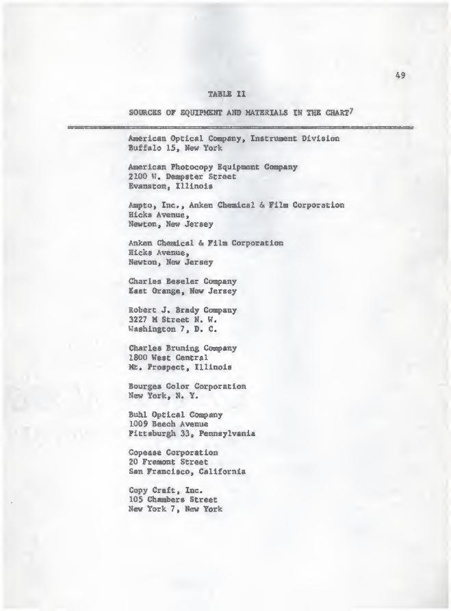
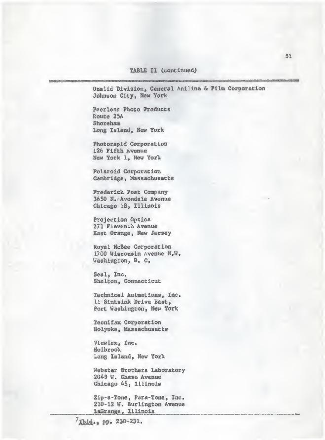
II. Sources of Equipment and Materials In the Chart ....... 49

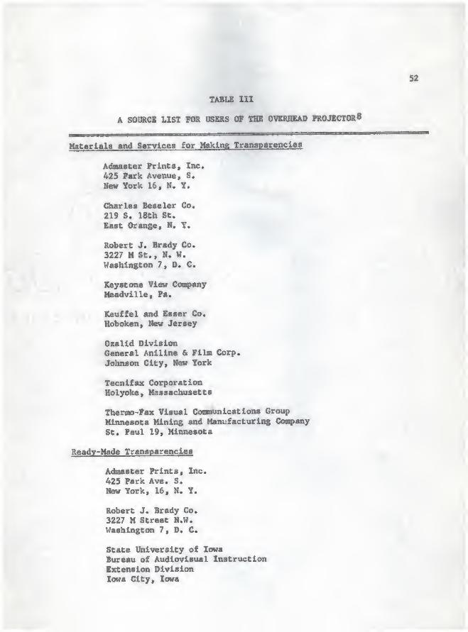
III. A Source List for Users of the Overhead Projector 52

:v\-'^>

LIST OF FIGIRES

riGURB PAGE

1. Proper and Inproper Placeaent of the Projector and Screen

Within a Classroom for Obtaining an Unobscured View .... 12

2. Nomal and Keystoned Projection Images 14

3* Proper Placement of the Projection Screen in Relation to

the Line of Projection to Avoid Keystoning of the Image

When Using the Elevated Screen 15

4. The Placement and Operating Principles of a Rear

Projection Device 16

5. Template for Determining Minimum Image Size on the Basis

of Screen Size and Maximum Viewing Distance From the

Screen 18

6. An Illustration of the Proper Method of Laying a . (^

Transparency on a Base Mount 22

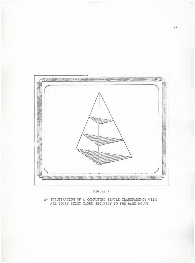
7. An Illustration of a Completed Single Transparency with

All Idges Being Taped Securely to the Base Mount 23

8. An Illustration of a Transparency Utilizing the Trap Door

Principle for Progressive Disclosure of Material 24

9. An Illustration of How an Overlay May be Hinged to the Base

Mount by the Use of Tape 26

f

s

FIGURE PAGE

10. Multiple Overlays that Have Been Tape-Hinged About

the Sides o£ the Base Mount 27

11. An Illustration of the Technique of Taping Transparencies

So That They Will Fold Together to Form a Composite

Image 28

12. An E]q>loded View of a Series of Overlays Where GuoiMd

Coawsrclal Hinges Designed for Stapling to the Base

Mount Have been Used Instead of Tape 30

13. A Device for Adapting the Overhead Projector for Use

With Mounted Photographic Slides 33

14. A Device for Adapting the Overhead Projector for Use

With Fllmstrlps 35

15. A Detailed View of a Device That Can Be Made When

Prograa«d Instruction or the Revelation Style of

Instruction Is to be Employed 36

. r

IMPORTANCE OP THE PROBLEM

Due to ttM Increased population o£ our country and the ever-

Increasing emphasis on education in recent years, educators have become

aware and concerned about the £act that newer and more effective teach-

ing methods are constantly needed in order to train the youth of today

to be effective mesibers of our society.

Learning begins with the stiiaulation of the senses. When more

than one sense is involved, the likelihood that learning will take

place is incraaaad. Words, either written or spoken, are often in-

adequate to convey the precise meaning intended. Since understanding

is rarely for long in the nlnd of the student, instructors are better

able to reach them by the use of audio-visuals.

The results of numerous studies indicate that from 73 per cent to

85 per cent of everything we know was learned through the eyes, while

only 7 per cent to 13 per cent was learned by way of the ear. If a

person is willing to accept these findings as reasonably accurate,

then it becooaa iMwdlately apparent that the visual medium is most

iiq>ortant to an effective and informative presentation. When properly

used, audio-visuals enable the students to understand better and learn

more - up to 35 per cent more in a given time with a 55 per cent longer

retention period.^

^The Overhead Projector . Audio Visual Aids in Training . Part I.

(Chicago: Office of the Army Signal Officer, Headquarters Fifth UnitedStates Army, 1962), p. 2.

2

One of the country's major oil companies^ lists the factors behind

how we learn as:

Through Taste 1 per cent

Through Touch ..... 1% per cent

Through Saell 3% per cent

Through Hearing .11 per cent

Through Sight 83 per cent

This saine company also stated that the learner's ability to

retain the Information studied could be analysed as follows:

What they read 10 per cent

What they hear 20 per cent

What they see 30 per cent

What they see and hear 50 per cent

What they say as they talk 70 per cent

What they say as they do a thing ...... 90 per cent

Within this saas study, the percentages of recall with various

types of instruction were given as:

Recall Three Recall ThreeMethod of Instruction Hours Later Days Later

Telling when used alone 70 per cent 10 per cent

Showing when used alone 72 per cent 20 per cent

When a blend of telling 85 per cent 65 per centand showing is used

2Socony - Vacuum Oil Company Studies

3

One such development in recent years is the increased use of

audio-visual aids in classroom teaching; and of these aids, perhaps the

oat versatile is the overhead projector.

A great deal of research has been done by both civilian and

military agencies to determine the value of the overhead projector

as a teaching aid and to develop projectuals to accoaq>any many dif-

ferent courses, but little has been published on how to use this device

in particular situations and areas. This is due to the idea that since

the overhead projector is extremely versatile, it can best be used by

letting the individual teacher use his own initiative and ingenuity in

designing and using materials in such a way that will best satisfy his

own particular needs.

The one thing that has been learned from previous research is

that the overhead projector is merely an aid to the teaching process

and that it cannot be used effectively as a replacement for the teacher

or the text.

Even though there are some disadvantages in using any teaching

aid, it will be found by anyone using the overhead projector that its

advantages far outweigh its disadvantages, especially when it is com-

pared with other projection devices.

STATEMSNT OF THE PROBLEM

It was the purpose of this study to collect and compile information

and data concerning the versatility of the overhead projector from

sources not readily accessible to the classroom teacher.

PROCEDURE OF RESEARCH

Tha Method of investigation £or this study consisted o£ the

reading of related materials found in books and Journals in the Kansas

State University library. In addition, many convanies supplied liter-

ature and brochures upon request which were analysed for usable content.

Personal or direct observation of mathematics classes in the

Manhattan High School over a three year period was also used.

EQUIPMENT NEEDED

Depending on how extensively the overhead projector Is to be used»

the amount and types of equipment as well as the cost will vary greatly.

All that is really necessary is a projector and some sort of projection

surface, several sheets of clear acetate plastic, and either grease

pencils or felt tip markers.

Equipment may vary widely. As an example, over a dozen companies

have been found, each of which manufactures several models of projectors

from 250 to 1000 watts as well as the accessory equipment. This equip-

ment consists of such items as the various transparency films, prepared

transparencies in different fields, pointers, film strip adapters,

tachistoscopes, and polarising lens attachments. In addition, soma

companies recently have begun manufacturing self-contained rear pro-

jection units and light tables to aid in the make up of transparencies.

Because of the wide selection of equipment available, the cost

of equipping a classroom can be as little as $100.00 or well over

s

$1000.00, depending on Individual needs and availability of funds. This

wiy sees like a rather large investment, especially for the snail school

systen, but considering the nuober of years that an item of this nature

will be used along with the fact that there are a number of items that

the individual teacher can make for himself, the cost is relatively low.

In addition, state and federal funds are now available to help in equip-

ping classrooms.

liOMIIfM>E ACCESSORIES

As was mentioned before, there are a number of things that the

individual teacher can make for himself which help to keep the costs

to a minimum. Some of these items are: a light table, pointer, adapters

for using film strips and slides, transparencies and mounts, and with

a little Ingenuity, a polarizing lens arrangement to give the Illusion

of motion within the projectual.

ADVANTAGES

In working with the overhead projector and the various types of

transparencies and overlays in mathematics classes, a nuad>er of signi-

ficant advantages have been discovered over other types of visual aids,

and especially over other types of projection devices.

First of all, the projector is in front of the group enabling

the speaker to maintain direct eye contact with the group at all times.

Such a position is a considerable help in maintaining student interest

-1- ..+

and when classroom discipline is a probles. An additional advantage

is that the teacher may use a more normal tone o£ voice in his pre-

sentations.

There is no need to darken the room during a presentation. With

the use of the more modem high-intensity bulbs, merely shading the

projection surface is sufficient, thereby allowing the students to

take notes at the aoM time the material is presented. This aspect

also reduces the time necessary in setting up a classroom before a

presentation as well as reducing the likelihood of student inattention

and drowsiness. In addition, both audience and presenter are fully

visible at all times and there is no real reason that the picture must

be kept on the screen at all times.

The students see what is written as it is written and everyone

sees the same thing, thereby eliminating the delay caused by the

instructor having to face the chalkboard to write something and block-

ing it from view until it is colI^>leted. This delay is unnecessary and

is often a cause of class disturbance when students become restless and

begin talking. The projected image will tend to hold the attention of

the class better. The interest of the class is on the work and not on

the teacher personally.

Where space is a problem or where chalkboard space is limited,

the overhead projector can be used as a replacement for the chalkboard

or as an extensfon on the existing board space.

7

Use of this device can result In a considerable saving of class

tine. For instance, if there is a test to be handed back that several

different classes have taken, it is much simpler and faster to put the

answers on a transparency thereby saving the existing chalkboard space

for further explanations.

The overhead projector can be used with any age group and with

any type of subject aiatter. Remembering that this is only a visual

aid, it is the instructor's presentation that will vary with the group

and the aids can be made to suit the presentation.

The overhead projector is extremely simple to operate and main-

tain. Only one person is required to operate the machine and anyone

who can hold a pencil can make a presentation by writing either on tha

glass top or on clear plastic sheets. The overhead projector tends to

complement the presenter rather than replacing him and at all times,

the presenter controls the projector, taking a prominent part in the

presentation. Due to the simplicity of its controls, no special skills

or training are necessary in order to make an effective presentation.

Even the most rudimentary art skills can produce dramatic, effective

transparencies. In addition, this device will operate indefinitely

without overheating and damaging the transparencies and without offering

any discomfort to the operator. With reasonable care being taken in

everyday operation, the only maintenance required will be the occasional

replacement of the lamp.

The overhead projector also lends ltsel£ well to programed

Instruction. First of all. It is an ideal tool for introducing

students to any type of programed instruction. Since the instructor

actually handles the programed text and uncovers or discloses the

respoiuies at a rate that he feels is satisfactory, the possibility

of looking ahead at the desired responses or "cheating" is thereby

eliminated. It is also an ideal tool for the individual teacher who

wishes to develop his own programed units, for it can cut the working

time almost in half. Finally, it is ideal for this type of presentation

in that it allows the students to work at their own rates. But per-

haps the overhead projector might serve its most iiq>ortant function

by making programed instruction an integral part of classroom teaching,

thus getting rid of the stereotyped idea that it is for individual use

only.^

And above all, the overhead projector permits variations and

originality in the instructor's presentations. One example of this is

to intermix positive and negative transparencies so as to ease the

eyes of the audience. Color, which is used primarily to clarify

points made on the screen, can also be added to lend variety to the

presentation. Using a pointer, especially when explaining graphs and

tables, also adds variety. Another method that is often used to add

Dr. James I. Brown, "The Overhead Projector ... Prime Aid for

Programed Instruction," Education Age. I, (September, 1964), 30.

i..-^^

^.

V -' \

9

variety as well as a oiethod of keeping audience attention Is to vary

the length o£ tine that the visuals are left on the screen.

The overhead projector Is extremely flexible In Its applications.

It can be used to help present new material or it may be used to aid

In a auasMry or review. It night be used In test giving or when the

teacher returns tests and It might also be used to give Individual help

to a student or a group of students without disturbing the rest of the

class. It might also be used by the students themselves In showing

their work or In making suggestions. The horizontal stage allows

the operator to write or draw extemporaneously and at the same time to

use a pointer to call attention to details of the presentation. The

operator can project a variety of transparent, translucent, or opaque

solids, animated devices, and fluids, or he can use the overlay method

of presentation with several layers of film, unmasking them in pro-

gressive disclosure or building them up to form a composite image.

Among the list of translucent objects that may be used in

presentations are clear plastic rulers and protractors with black

markings and the transparent slide rule.

Opaque objects, which project only as a silhouette, may also

be used quite extensively in science and mathematics classes. A few

exaaiples are gears, magnets, and the abacus. ' .

There is a wide variety of materials available to either the

individual or to the school system. These Include different machines,

prepared masters, prepared transparencies, different types of films

10

to satisfy different needs, different mounts for use on different

machines and In different situations, and hinges for the use with

overlays. There are also devices available by which a person can

add color to his presentations.

Transparencies up to 10 Inches by 10 Inches can be used, thereby

greatly simplifying the preparation of the artwork for the transparencies

and In w>sC cases, photographic reduction of the original artwork Is not

necessary for the production of transparencies.

The transparencies themselves are light, long- lasting, easy to

clean, and easy to store or transport for ready reference. Once a

transparency Is made. Its form Is penunent. Even though the plastic

sheets auy pick irp static electricity in dry weather, they are by no

means a hygroscopic material.

DISADVANTAGES

As with any other device, the overhead projector has advantages

and disadvantages. First of all, prepared masters and prepared trans-

parencies are extremely costly and they may not serve the exact purpose

the instructor has in mind. At the time when this was written, prepared

Misters cost from $1.00 for a single set of 23 masters up to $140.00 for

a set of over a hundred masters to cover an entire course. Prepared

transparencies would cost from $1.50 for a single mounted transparency

to over $600.00 for a set of eighty which would cover an entire course.

n'- . > -

• .

> -'. '. '-A^ ^ A •

i

n

A person attempting to make his own set of transparencies for a

particular course will find that the process Is largely a matter of

practice and experience, and that at its best, the drawing of the

asters and Mounting of the transparencies is extremely time consuming.

The grease pencils and colored pencils are also very soft and are easily

broken if not properly handled.

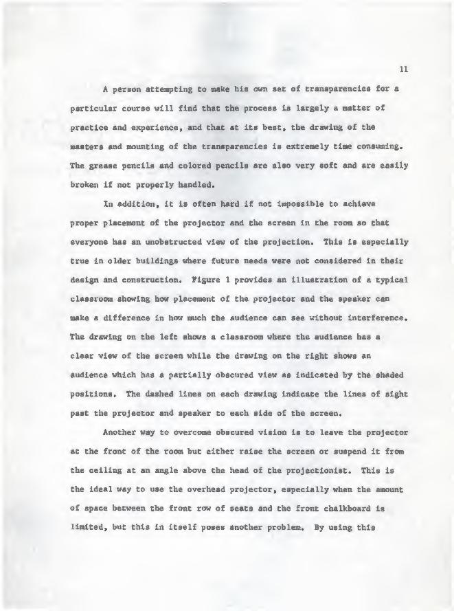
In addition, it is often hard if not impossible to achieve

proper placement of the projector and the screen in the room so that

everyone has an unobstructed view of the projection. This is especially

true in older buildings where future needs were not considered in their

design and construction. Figure 1 provides an illustration of a typical

classroom showing how placement of the projector and the speaker can

ska a difference in how much the audience can see without interference.

The drawing on the left shows a classroom where the audience has a

clear view of the screen while the drawing on the right shows an

audience which has a partially obscured view as indicated by the shaded

positions. The dashed lines on each drawing indicate the lines of sight

past the projector and speaker to each side of the screen.

Another way to overcome obscured vision is to leave the projector

at the front of the room but either raise the screen or suspend it from

the ceiling at an angle above the head of the projectionist. This is

the ideal way to use the overhead projector, especially when the amount

of space between the front row of seats and the front chalkboard is

limited, but this in itself poses another problem. By using this

12

o o.o o o oo o!o o o oO OtO o o oo o|o o o oo o°o o o o

oMP»4

o

ooa:COCO

33H

re z

o <Hz o

tJ

to

ft2

wo

Gz<

w

§PL4

% • >. - *-'

\ \ : 13

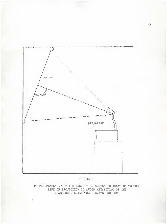
technique » the user will often achieve a distorted Image on the screen.

This distortion is the effect known as keystoning in an image and is

caused by the line of projection not being perpendicular to the screen.

The result is an image that is wider at the top than it is at the bottom.

Figure 2 shows this difference between the normal and the keystoned image

and Figure 3 illustrates the proper way to position the projector and the

screen when it is in the elevated position so that the line of projection

is perpendicular to the screen.

Another way to overcome the problem of limited space and ob-

structed view is to use a rear projection device as is illustrated

in Figure 4. With this device , th« image is first projected at an

angle onto a mirror behind the screen. The light rays are then re-

flected forward onto the back side of a translucent screen at which

time the image is viewed on the front side by the audience. Since the

image is projected onto the back side of the screen and the light neces-

sary to illuminate the screen must actually pass through it, a greater

light source is required within the projector. The screen and mirror

are normally enclosed in some sort of protective casing to help shield

against the entrance of outside light, and also to keep the mirror in

the proper position relative to the screen. In addition to being a space

saver, this method has two other very definite advantages. First of all,

the whole device can be made to be movable and secondly, the size of the

projected image can be considerably enlarged without having to move the

projector any great distance. This is true because of the fact that the

14

keystoned image

normal image

o

FIGURE 2

screen

NORMAL AND KEYSTONED PROJECTION IMAGES

15

\\\\\\\\\\\\\\\

projector

FIGURE 3

PROPER PLACEMENT OF THE PROJECTION SCREEN IN RELATION TO THELINE OF PROJECTION TO AVOID KEYSTONING OF THE

IMAGE WHEN USING THE ELEVATED SCREEN

16

mirror

\ s

\speaker

\projector

\ ^^^^reen

^v/

*

o oaudience (clear view)

o o,.

o o o o o o-

o o o o o oo o o o o oo o o o o oo o o o o o

FIGURE 4

THE PLACEMENT AND OPERATING PRINCIPLES OF A REAR PROJECTION DEVICE

WT^

17

image will enlarge proportionally with the distance from the screen

and with the rear projection device, the light rays are partially

doubled back toward the projectionist.

Another problem that is frequently encountered %ihen using the

overhead projector is that the lettering or writing on the projectual

is not large enough to be seen by those persons in the rear of the

audience. This can be overcome however by the use of a simple template

guide which will help the individual determine the proper sise lettering

which can be seen clearly at the maximum viewing distance from the screen.

Figure 5 shows an exaiq>le of such a guide.

For exas^le, if the screen size is 40 inches by 40 inches and the

maximum viewing distance is 36 feet, then the minimum image height on

the original must be as high as the clear area on the tein)late at the

points. In the figure shown this height is illustrated by the letter

"A" which was drawn in to help clarify this example.

With the saaM screen size, but a longer viewing distance, this

image height must increase. With the same viewing distance, but a

larger screen, this image height may decrease.

Proper viewing distance and screen size for an existing trans-

parency may also be found with this same template method.

.-yj18

V « ,.'

Screen

TEMPLATE FORMINIMUM IMAGE SIZE

Siz^(inches)

96 X 96

84 X 84

70 X 70

60 X 60

50 X 50

40 X 40

36 X 36

5 15 25 35 45 55 65 75

Viewing Distance from Screen (feet)

FIGURE 5

TEMPLATE FOR DETERMINING MINIMUM IMAGE SIZE ON THE BASIS

OF SCREEN SIZE AND MAXIMUM VIEWING DISTANCEFROM THE SCREEN

b' "- '

'.

-.

'

.V ' '",'

it J . ^'"'s"/""^"^"j .-'-

makdk; and mounting the transparencies

The permanent transparencies constructed for use In this study

were all done on Therraofax type 125 extra quality positive transparency

filn so that color could be added by colored pencils. This particular

type of film also has a thickness which makes it more durable with re-

peated usage than other types. There is also a negative type of film

available at a lower cost and various one color films at higher prices,

but for general use, the positive film is probably best from an overall

standpoint.

To distinguish between the positive and negative type of trans-

parency films, the positive type develops an opaque image on a clear

background %rhlle the negative type will develop as a black image on «

clear background.

The two main reasons the Thermofax process was selected over

other duplicating processes were cost and convenience. The overall

cost of a set of transparencies. Including tapes, film, the mounts,

and the coloring devices is much lower than any of the other duplicating

processes. On the average. It costs approximately 17 cents to make one

transparency so that it is ready for presentation, but even at that,

the cost is only about half that of the other processes. The next

reason was convenience because it is a dry photographic process that

allows the transparencies to be used immediately after development

without any need for drying.

10

For the individual wishing to make his own transparencies, there

are some things to be considered before he actually starts to work.

First of all, subject matter must be considered. What ideas

or concepts need to be presented? What specific points, processes,

operations, or ideas need visualizing, and in what order? Is the

purpose to present information or is it to present problems in order

to find a solution? Is more than one subject to be presented? Are

there other speakers to consider? v

The next item to consider is the audience. What is their back-

ground and vocabulary? What related experiences have they had? How

large an audience can the teacher expect and how does he want them to

react?

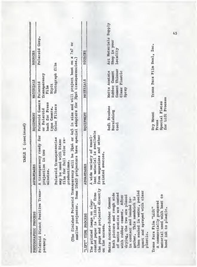
Finally, he oust decide on the method of production. This

might be the handmade process, the spirit duplicator method, a photo-

graphic process, a "lift" type process, the diazo (aononia) process,

or the Thermofax process. A complete explanation of how each of these

processes works and the equipment necessary is to be found in the tables

in the appendix. The teacher must also consider the number of trans-

parencies needed as well as the time involved and the overall cost.^

Depending upon what the individual feels would Biake the most

effective presentation, either the single transparency or the multiple

overlay style may be used.

transparency Preparation Methods . (Fort McPherson, Georgia:

Pictorial Division, Signal Section, Headquarters Third United StatesArmy, 1962), p. 19.

/ .

.-^ '. y.- «i

The single transparency may be either mounted or unmounted.

This is strictly a matter of choice and certainly does not add to or

detract from its effectiveness, but the cardboard mount will give the

transparency more strength and support and it will also keep it from

warping or curling. Figures 6 and 7 show the procedure for laying

the transparency squarely on the mount and then taping all edges

securely to the mount.

One very effective way to use the single mounted transparency

is to use the trap door method for a progressive disclosure or develop-

ment of material as is shown in Figure 8. To use this method of

presentation, a series of thin cardboard flaps are attached to the

base mount by the use of tape or transparency hinges. These flaps

are then raised by the instructor at his discretion to disclose some

concept or procedure. This is a very useful tool when it is important

that everyone sees and understands the same things at the same time or

when showing a necessary sequence of events. One should be aware of

the fact that when more than one figure is placed on a transparency,

the projected image is reduced in sise. This means that either the

projected image must be enlarged or the audience moved closer to the

screen.

If the overlay system is to be used, there are two things to be

considered. First of all, it must be decided what will have to be

placed on each transparency in order to make the most effective

presentation. Secondly, how are the overlays to be attached to the

22

transparency film

mount

FIGURE 6

AN ILLUSTRATION OF THE PROPER METHOD OF LAYINGA TRANSPARENCY ON A BASE MOUNT

ff^?;

23

FIGURE 7

AN ILLUSTRATION OF A COMPLETED SINGLE TRANSPARENCY WITHALL EDGES BEING TAPED SECURELY TO THE BASE MOUNT

24

FIGURE 8

AN ILLUSTRATION OF A TRANSPARENCY UTILIZING THE TRAP DOORPRINCIPLE FOR PROGRESSIVE DISCLOSURE OF MATERIAL

ts

base mount? Since the transparencies are clear, there Is no significant

loss in light intensity for any given number of overlays.

The one big problem with overlays however is how to affix them

to the base mount. This hinging effect may be accomplished either by

the use of tape such as a good adhesive masking tape or mending tape,

or by the use of commercial transparency hinges. During this study,

it was found that the aluminized mylar hinges made by the Tecnifax

Corporation are much more durable and more attractive than the various

tapes. Figure 9 illustrates how tape may be used to attach the overlay,

or overlays, to one side of the base mount while Figure 10 shows how

more than one overlay may be arranged about the sides of the base mount.

Still another way to use the overlays, either mounted or unmoiinted,

is to attach thea so that they will fold up on top of one another as

is shown in Figure 11.

If the guaned, coanarcial hinges are to be used there are

several steps that should be followed for their successful use. First,

all overlays must be arranged so that the image of each one is in the

proper position with regards to the one prior to it. The overlays aust

all be marked so as to insure proper placemant of the hinges along

the edges of the sheets. The gummed hinges are then attached so that

about one-fourth inch of the hinge is attached to the plastic. The

remainder of the hinge is then folded over on itself, allowing about a

quarter inch to be attached to the bottom side of the plastic as was

done on top. This will form a tab made up of two layers of the material

26

FIGURE 9

AN ILLUSTRATION OF HOW AN OVERLAY MAY BE HINGEDTO THE BASE MOUNT BY THE USE OF TAPE

27

FIGURE 10

MULTIPLE OVERLAYS THAT HAVE BEEN TAPE -HINGEDABOUT THE SIDES OF THE BASE MOUNT

28

FIGURE 11

AN ILLUSTRATION OF THE TECHNIQUE OF TAPING TRANSPARENCIESSO THAT THEY WILL FOLD TOGETHER TO

FORM A COMPOSITE IMAGE

29

and extending outward from the edge of the overlays approximately one-

half Inch. The overlays are then arranged In their proper positions

again and the tabs are stapled to the base mount as Is shown In Figure 12.

This coiq>letes the procedures to be followed when using prepared hinges,

and will result In a set of transparencies that are extremely neat and

strong.

Color may be added to the transparencies In a variety of ways.

When using negative type films, the teacher may add color by the use

of colored adhesive films. To use this material, simply place the film

over that area of the transparency to be colored and cut around the

outline with some sharp Instrument. The protective covering Is then

stripped from the adhesive side and the film Is applied to the desired

area of the transparency.

Color may be added to the positive type transparencies by the

use of colored adhesive films and tapes, colored acetate Inks, felt

tip markers, colored grease or marking pencils, and by the use of color

transparency films. When developed, these films will produce a trans-

parency which Is entirely In one color.

Filing of the completed transparencies may be accoiq>llshed by

any one of several siethods. One method Is to simply group the trans-

parencies by the chapter they correspond to In the text. Each trans-

parency Is then given a number to Identify It with one particular section

or part of that chapter. This necessitates the making of a master Index

so that the Instructor will always know what he has and where It can be

found.

30

staple

FIGURE 12

AN EXPLODED VIEl^ OF A SERIES OF OVERLAYS WHERE GUMMEDCOMMERCIAL HINGES DESIGNED FOR STAPLING TO THE

BASE MOUNT HAVE BEEN USED INSTEAD OF TAPE

31

Another method of filing or organizing the transparencies in a

course is by the use of edge-punched base mounts.^ These are similar

in appearance to the Hadley Uni-Sort Cards and the Royal McBce Keysort

Cards used to file information according to predetermined classifications.

To use r-his method » it is first noticed that the holes about the edges

of the mount are numbered by groups. These groups may indicate classes,

grades, week, month, subject, chapters, type of material, an original

or master copy number, or a series nutnber. The numbers are used to

indicate some predetermined subdivision within each group. As soon as

the instructor determines the data on each transparency, he then notches

the holes in each group that correspond to the data he has affixed to

the transparency. This is done with either a hand notcher or some sort

of electric notching device. The transparency is then filed along with

all others to be used.

When a transparency is needed for any one particular subject or

area or when all transparencies in a certain area are desired, a "needle"

or long, slender rod is inserted through the hole corresponding to tlie

data or classification desired. The rod is then raised, allowing the

properly notched cards to fall out for selection.

The mounts themselves are 101( inches by 12 inches so that any

standard file cabinet or drawers can be used. In addition, the mounts

t " 5J. Francis Runnel, An Introduction to Research Procedures in

Education (New York: Harper and Brothers, Publishers, 1958), p. 269.

92

are heavy enough so that standing the mounted transparencies on edge

Is not harmful to them. This is actually to be desired rather than

laying the transparencies down flat for storage.

For the person attes^ting to prepare his own Thermofax masters

or originals, it should be noted that these can be drawn or written

up on any low rag content paper using any type of carbon base marking

device. For maximum results with the Theirmofax process, white paper

is to be preferred, but any light colored paper is acceptable as long

«• it Is reasonably flexible.

SPECIAL DEVICES

Thttrs are a nuaber of attachasnts which can be purchased for

use on or with the overhead projector, but for the average person

they can Just as easily be handmade. With a little care taken in

their construction, a slide adapter and a film strip adapter can be

developed which are Just as attractive and durable as any that can be

purchased.

Figure 13 is an illustration of how a device for projecting

photographic slides can be made from a piece of posterboard or some

similar material. First, the cardboard is cut so that it completely

covers the light table of the projector. A hole is then cut in the

cardboard the exact size of the film in the slide and a piece of

cardboard is then glued on either side of the hole to serve as a guide

and centering device for the slide mounts. The distance between these

33

FIGURE

A DEVICE FOR ADAPTING THE OVERHEAD PROJECTORFOR USE WITH MOUNTED PHOTOGRAPHIC SLIDES

34

strips Is equal to the outside measurements of the mounted slides.

Figure 14 shows how a similar device may be constructed for

use with film strips. For this device, two pieces of cardboard are

glued on either side of the aperature - the top pieces being slightly

larger and forming a small overhang on each side. This will enable

tha film strip to remain centered over the aperature while at the »mm

time remaining perfectly flat against the base. The film strip is then

pulled through by hand at the desired rate.

Another device that can be easily made is a pair of rollers

attached to opposite sides of the projector's light table. A 100 foot

roll of clear plastic is then placed on one of the rollers with one

end of the roll running across the top of the light table of the pro-

jector. With the use of this continuous roll device, a person can

write for a full hour or more without having to erase or clean off

the plastic.

Another device that is extremely useful is made up of two

Identical mounts placed together with a thin shim between them along

two opposite sides. The transparency is taped to the inside of the

bottom mount in the conventional way and the mounts are stapled to-

gether along the sides containing the shims. Cardboard strips are

then slipped between the mounts through the open ends, thereby cover-

ing up any material on the transparency until the instructor chooses to

disclose it. This device, as Is shown in Figure 15, is particularly

applicable to programed instruction or to the revelation method of

35

FIGURE 14

A DEVICE FOR ADAPTING THE OVERHEAD PROJECTORFOR USE WITH FILMSTRIPS

36

FIGURE 15

A DETAILED VIEW OF A DEVICE THAT CAN BE MADE WHEN PROGRAMEDINSTRUCTION OR THE REVELATION STYLE OF

INSTRUCTION IS TO BE EMPLOYED

37

teaching where only after a suitable response has been given is the

answer disclosed.

Two more devices that are sonetines found in the classroom are

the tachistoscope and the polarizing lens attachatents.

The tachistoscope attachment to the overhead projector is a

device closely reseBd}ling the shutter arrangement on a camera. The

amount of opening cannot be varied but the length of time that the

shutter is open can be controlled. This timing device can be either

mechanically or electrically operated. There are also models available

that are hand operated - where the iterator oust cock the shutter each

time and then manually release it.

These devices are most cooBKmly used in the teaching of reading

but they can also find application in any subject where speed or time

is an important factor or where rapid identification is one consideration.

By definition, polarization refers to the action or process of

affecting light waves so that the vibrations assume a definite form or

pattern. This is achieved by a specially ground lens that is rotated

in a fixed position relative to the light rays entering. The importance

of such a lens is that if an image is being projected along the light

rays when passing through such a lens, the effect is an illusion of

motion on the projection surface.

The polarizing lens attachment finds its application in the class-

room as an atcacbzaent to the lens barrel of the overhead projector.

Normally, the lens is rotated in a plane perpendicular to the light

Mrays by use of a small electric motor and gear arrangement. It can

also be turned by hand, but either way, some allowance snist be made

to control the rate or speed of rotation. By varying the speed at

which the lens is rotated, the apparent rate of motion of the pro-

jected material can be speeded up or slowed down.

One caution though; If a person is making his own transpar-

encies he must Incorporate im}tlon symbols into the drawings and these

must be of near professional quality if the proper effect is to be

achieved.

SUMMARY

In this study, observations were made on the geometry classes

at the Manhattan High School over a three year period to determine

the usefulness of the overhead projector as a teaching aid. Illus-

trations and directions were presented in this paper for determining

the type and amount of equipment needed in a classroom, items that

can be made by the teacher, methods of making and mounting the trans-

parencies, various styles of presentations, organizing and filing

of the prepared transparencies, and special devices for use with the

overhead projector. A large number of advantages, as well as a few

of the problems and disadvantages, were determined and discussed,

but since no statistical controls were applied, no definite con-

elusions could be reached.

39

On the basis o£ the observations made during this study, ttw

only recommendation that can be made Is for the further use of the

overhead projector and the continued experimentation by other teachers

in all teaching areas.

• ^'4:"-.

BIBLIOGRAPHY

41

BIBUL06KAPKY

Brown, Or. J«ms I. '*Ib« Overhaad Frejactor ... Frlat Aid for

PrograMd Instruction/' Bducatlon Aite . I (S^tMber, 1964),

30 - 33.

The Overhead Projector . Audio Vlaual Alda Ija Training , fart I.

Chicago: Office of the Ktwf Signal Officer, Baadquartera

Fifth Oolted Statea AraQr, 1962, 2.

Pearson, Neville. '*Iran8parency, Typea, Tools and Techniques,**

Audiovisual Inatructlon . X, (April, 1962), 228-231.

Riagaal, J. Francla. An Introduction to lU^earch Procedures jLn

MMffcies* lav York: Harper and Brothera, Publlabera,

19St.

Socony - Vacuum Oil Coapany Studlea.

Tranaparency Preparation Methoda. Fort McFheraon, Georgia: Pictorial

Dlvlaltm, Signal Section, Ileadquartera Third United Statea Anqr,

1962, 19.

i-f

APPENDIX

g

mu

S "^O uf-i an o

•o o•r4 0)

43

o

uou

au4)H

4J

£ S u M 41 0>

o aik<

t >» « a «!§ 1S >4 h h 4J -H 4J

•w a « « e u o um n u a. 9) e V U 00 (0

ar. n

orlear

ke

ma

trans erman

ed

pe

proj

lor.

C B Ut) -rt

M 4i • O« -rl O U«a 3 4J 0)

simil Krylo;

lar

c

to

ma

nore

and

pColor which

in

CO C (Oh-)<t u « oW O •-* M

ft m «o u u «B B o4> •^ m oa. O u •

a « «>> i-i >M «Ju i-i 1-4 h •r*

s cS9CO ^

•H Ao B 4> 9

s ^ 0,4J ?.

goZ

• >%

o a 2« «•^ > 4JQ.-a s ,

2-l§J3 •H

u U WCO -rH t4 U9 > •1 0)

I-I "-1

« •« eB M 0) M •

u a-o«M «o ja n

l3 a ^V o «

tiJ ^^J}M O u 4J

1

to

'

«o >»rH

s

V* .2e • •r4 o.«i n UU -4 « c<a t-i 4J •oa o

a J .gB » u•1 u W 9 uU4J "S O JO

(0 •r* *J

§1ii %u g

B (0g>

•w •»4 « 1-r

u ~ > o *jH O

1^•H

h 1-1

at

I

«

OOu

^4J

g %gxo a

f-l h « •

U •<•* •rA a u bO B 4)9 <M

« a wi 4|iH r-l a a«M e04J o o B

•H I-I -w >M >4 -r^

8 9 S^a^ «B 4) 4) 4) >SU•r4 U

n

saat

ou

us

easil

dof>% 60 -^ •H 4)

« OB O I-I • « I-i •

Vi n B >t « u« (t 4J 4) 0) ^ f-l 1-1

U 4) -rt Jia<-i O W 4) a • 4J

« u 4) -H W tj

4» -H «u (M J3 U « •H W «J

• O. 4) «H » OB -O M 9 •

5 U 4)If ^ 4) TJ >4 (4-1 V4

1 B 4J J3 ;i< a O TJ

1

«r-l «J

giS

Isis

ing

on

wax

(car-

Whe

ear

plastic

of

4) 4J l4 1-4 4>

O JQ «O U -r*

ftl^•O JS 4J

-... 4J o

M >r( Ki «l

o » O *J

g'.a ftv4 4J ^4W « *i /->•r4 « •H dK <-* M O» a » .B

sti

a

5h4)C4J«>4J•«o

u1 1 -HC « 4JV C au « «OS M r-i

^ H 04

a-d *<M S y« 3 dM U« f-4 »4

« -H «O y a

1 r-l

O -r*

« y<-* aM «

4J

g«.<w y .^tt -^ in

1i§l• 4) uS

§•rl 1 •Hu (0 c ao « 1-t oa 4) y

o'u 1 0)0,4J o 4J

3ui

T-*

o t-l •r<

>M « ftCB o Ck

JN 4) 3u 01 l-i •oc ^0) 4J M .MM 4J« U 3 Wa 01 8a we 0) T* y« •o c Wi

MH g^ o

ycMOUu•r4

ot

,

U9 4)U U

a >«4) 4i «^ 4» i4

y aH < CO

O 4) Mu U 10

*j d W 4>•H o

Sc^

u u•H oM «

yO -H

I

4>

youSUM4) <H 14

a M ao a

^ « o

^ uu u•r^ O O

r-( S «4J Uu « w4) jS S

t >»u« • dU >v 3

M n a a M

^g"5 a 4> %^ut» ii< "-^ e a

§11a 3 4i o «4J d •H a a

" ^s Id u 3•o u a 4*

••H Q) u y 4) 4Ja 4) u M j3 ct3 V4 S1 4)

u -a i-< 4J 4J4) d 0. _ 4>

4) *J U <M a 3 d y4J a n •o -w a» a tMa B •-'

d r-l

a -r* 0) T) Q)

^«5 u y4i d

O. 4) 4J>^ V4 4J

• •o 4) • 4j (8 a• a 3•o a ^

4) 3 o>» Ai y•"! " t4 U 4)u J«! u •w u a

d "d 0) y 0) (0 M a••^ d d •3S a ^ •«M « -H 1-1 a a d04 J3 1-^ 0*4J o. (A <H a

a a 0)

d* Sii '^o uua ay -r1

ii y4) -Ha 4J

o a4J r-l

y»-i y 4J ^Cui-i a 4J3 4J aTS a t-t ^j

a a R0) <-! 4)

J3 Q. U r-t

u ay(M 4}

3 4J aO 4> J3

Jb JS -H du a 3 -H

^

44

14

omM -a 60sj- d d ij

I a -H dI 4J a. 41 V4a CO o a 4)

u ^ '-4 5. u>» a -rj d

O a 4) fi

IS.• a 41

a •-< N

9 a

^a

d 3•^ r-l -Oa a a3 T* u

u>» « boa ii o

a >»M

^1 § a15 1-4 u

•M3

oa >Ma a aD.^

3 5H a u

y jd 1M 60o •4J r-t d S

a •rl

js e a0.-H •O J

60 a 4JU -H 0.a u o ur-l o360 >^

1-4

Su^§ ^

•rl

a a<« a

§!a

aido

a a -H> > 4J•r4 ^ yij 4J a•-4 a •<-i

a 60 oo a MQ. S a

I

9

S

oB

O U

U «

a«00

u o

a u« d -H 2; ^-4 4 h o >O M0< H<au laat a •§ « * Wi

a •a M <a 0)

u -H eu M uo « r^

•rl c« o i hO 'H <M UMO Vj

« pk« jii at er-l U CLrHO M « >% O04 O JQ W U

41 O

« o

duo• « 4J

*^ "Z" 2u o e

«u

a•

o

r-* UO tt

A4 O.

45

is

^ o

UU » -M

js a u mU 0) « CO

0) ^ Oii-400 4J <« a

a

1} d .

ll e u u ay

Q O & It O • >tOuy* cjuQ. •o o •-< c o • •

• u •

1 g*

o u qsue o •• u o.

11 M CD a uH •,4 CO >t o M 4J ofj a h ^ 4J (^ « • OOM u o o q

oo •04auswoc4JO^^a©aCSMJJO MBlS-.^* o

fi 0-H* SCO UU (S-O• e •••^ 30C<-<« •! g •woa4J-4h9*4j3-Ho>apsiA«M

UMM^ ^< U U U U •< U

• M au o «n o . f ^fi • 00 o o u o u CO >tOi «> Q h*5

.

• -H "O O J3a » c o &4 CO -O « M S O4J -rl ^ fQ iB W09 ,

o eiO 3 O CO

3 (0 ••4 X M U MCO CO CL} 1-3 -• jd a

8 ss g 0) fU 0) a h b 01 (U oo 01 •-< r-i 4J ua

ocd o "w •« nU 3 »4 otT3 « Q) o VM fh M S »<

M u "O cs a CO

a< o «> >« S J3 hI

»< »M ec! > »

8 l:§l .I-*

6 <8 -rl1

S «M 0)

»M -H T) CS3 s O 00 UW « -H

i^7 fJ C 0)

s« c n«M

P^ Q •rl M

IS gJ^ss ^ ^Jdg

>t S 19S rH

g gM /-s a.« (U o4J U fH1

1

ja o g

1

1a M o

V o

1 4J 0) h :

ii .iSS u 2lM cd -^3 O C •

30-'so'oc90 moeo9* a u ou M• aU CBU4i «Hr-45. 4> P^-H O T» »M «ou>«a «wcbt4 o>\w_ a a o *j '->'-> i-ifo

O M O 09 r-l UCO CAM

«« -^ W « to -^ U •OMC(t -H a o o -w «

u Qg 2K 2 ectctf-iQ) oai CO2 2 i-lf4«)3U«-HU >\ >\^K s a. m -o n u a-w c a o

U4JttM-r^ialu9 XO.O

1 91 I

ao Tf u CO cuR 1 >t 60 « 1 --I -r^ a>%CO-MaHa •?0''r4«

< 3

"88.C « K 'O

- * «x) e »4 •> hi >•« ^ 1 U 9 jDuOb 0) v4<|)a

•H C « U 0)

8« CO at eo->4 H « 0) i-i 0) S

>» ^'r* 1 « « > «) tf oCOflCWU (i-l-ii^ 4)'O-H-<-i00«CB-r4>-l08)UhiQ'a T3CAC

o-4 «J 01 9 c ILI

^ C) 4J 00

QM sOT s

i

•f4 nsSiioac ui3-it4

-• - 2 H • «d O -H 3 «) c uvo-H ^ V4-F4a) dco*

4J U « U 0) -O hiM (k, Ai e ^•HO 1 JS 4 « i

t

K 4J C O r-»P4 2p4 «l U « M • u O

U4 Tt js M u ti or*^ p41 CLH <u «> w s ait400>>«u'a«) a. u a

^ 6 _ N-l « Jfl K1::

a a q) G a. 0.4JC ^ J 9 O « -rl

MJE

Q'5 >M •-4ooee>S>»a 5^q«Ma)«SB«oooS«din^M « H 4J u u « » 2r* 43

H

a oa".« M4J ttj

CO o X8

C04) •«

B C «OM il

i4J

gU\^

H

a

00e

U-OKOCiOO>« •-

oa 4J«JO cSHo0)

3 3 1-1

« c eI 1-«

O »4 C Mfi V « 0)

0) Cu B O.JQ O S OH U U U

U fl>

> to

>> « a

f* O 9 **

4J o "O w T)

^

c «5

M C « «

_ o • o y

3 o. S «< 0< 3 4J ,0

O V *i

^ « B •

3 u «go I-" <« nTt « 0) 00C O "O -^03 V 4 V4

» M S O

a

lbU CO

1^ »M C

O -<

•r-< >*-i Ct

O 0) 0)

U 3 (0 JJ

8

47

oou

5 -o

0) CS h VI tf.-1 1-j M O 1-t

(U > o g

m am•O *J «w

« 14 t4 -r* •» i-i ct a ca

^ (4 o « uaO O 05 H O4^

a

M g ^>> 4> e, "M4J 0< • n ft

•-< a «» Ai 0) M(d u c at)3 00 CO i4

=^5 1 « g^M«

•0•a o i4 i-» (1) u

flJ H •« r-* '-'

5 V< O C 3 3

M (0

W iH

•O _u e «-I 1-1 B43 «ft «

r-l « O•H l-t r-«

«« 1-1 o« u

8^n

OB >.'09 e «•H a • ^

I

I

01 « « 1

g4J h M tj

ga o

SJ M>« o O O

M f^ o f-<

•M a O^ a 0) « u<9 a

u 0) 0) tJ •o43 0) -0

u 0) H « CD

B h 3(d « O1-1 « 0) iJ1-4 n TS .ai-« »-4 O «iH « u >% >.U 1-1 « 2 CD

(Q W4 a•

I-l

«) 1 u a 1

4J s s 8-4J

Oua

«0 B 4J 4J «

1O

g»4CO

•s

?0) 3 * C( u4i f-i « B

c n S ID 0) i41-t

§B 0) 3 uCS 4J O* A

tt u «J CO

(0 a 4J « O.50) i-l O«M V4 44O o

S^«1-1 Ba 6 4J 1-1 i4

B a Mo 14 0) 3 O 4J

t^ i^ *ftja •a

iH »4 a fH ft »<Q (0 m « I-l

a B 14 *

(U V « M u 0)

43 u Vi 0) 4J43H Ct, 4J 4J O u

i w0) 4J O•O 0) U

q) uO 2 0)i4 « 1-1

3 Oi4 CO a•-< 0)

0) O .B43 U4J CO

u> « o•w 0) -Oa o. 0)

3 O UI-l C8

>» « '-4

n > o.

ai443 a

0)

43 g

ra 0) i4

"•Si•a *j y0) CO «a ft uo-I o» =0) u B> B O0) 0) I

•d i4 a•c o

CO 3 o>i4 « :

a

^

a

J3 «U U p. «C 9 (S M0) as H 9<o a O Xcu u u 0)

§ej o u-•"*• —h a> ca eH '-^ n <a

u «a a ^f-t O n n 0)

v4 et o 0) "Oh a p. « «4J N Ai U 9

.H O 60

O O 4) -rl

V4 f) -H O. Ci

48

ge 4> 4J « d H •

^ a) B Q "^ 4J •

m « 4J o &oCO

O M

^ d n u '-*"-> Q ^u o fit 4> n o0) -w ^ a N hH 4J u < o eu

81

4J a 8

I

w-* a

4J f-l

cCO

U *4

I) • U V4 ,oc u a CO

gnc u >

«> <

00B O

I

Ou uex, o

O Q4.B 0)

t4 u

^ SM B

Ot

TABUB II

SOimCES OF EQUIPMENT AND MATERIALS IN THE CHART^

American Optical Company, Instrument DivisionBuffalo 15, New York

American Photocopy Equipment Conqpany

2100 W. Dempster StreetEvanston, Illinois

Ampto, Inc., Anken Chemical & Film CorporationHicks Avenue,Newton, New Jersey

Anken Chemical & Film CorporationHicks Avenue,Newton, New Jersey

Charles Beseler Cosqpany

East Orange, New Jersey

Robert J. Brady Coiq>any

3227 M Street N. W.Washington 7, D. C.

Charles Brunlng Company1800 West CentralIfc. Prospect, Illinois

'.'

Bourges Color CorporationNew York, N. Y.

Buhl Optical Company1009 Beech AvenuePittsburgh 33, Pennsylvania

Copease Corporation20 Fremont StreetSan Francisco, California

Copy Craft, Inc.105 Chambers StreetNew York 7 , New York

so

TABLE II (continued)

CmnMc tbotoatapy Corporation80 Fifth AvwuieHew York 11, New York

A. B. Dick5700 W. Touhy AvwnMChicago 31 » Illinois

Ditto, Inc.

228S W. Harrison StreetChicago, Illinois

Basfian KodakBochester, Haw York

Foto Type1414 Roscoe StreetChicago, Illinois

General Photo Products CoopanyBOK 23Chathan, Mew Jersey

CSestetner Corporation216 Lake AvenueYonkera, Mew Ywrk

Zdeax Corporation150 Fifth AvenueMew York, New York

Keuffel and Baser ConpanyAdasM and Third StreetaHoboken, Mew Jersey

F. G. Ludwig, Inc.Coulter StreetOld Sayforook, Connecticut

Hinnasota Mining and Manufacturing Coopany8t. Paul 19, Minnesota

Mord Photoc<^y Corporation300 Denton AvenueHew Hlyde ParkLong lalwid. Maw York

51

TABLE II (continued)

Osalld Division, General Aniline & Film CorporationJohnson City» New York

Peerless Photo ProductsRoute 25AShorehamLong Island, Mew York

Photorapid Corporation126 Fifth AvenueNew York 1, New York

Polaroid CorporationCaaibridge, Massachusetts

Frederick Post Company3650 N. Avondale AvenueChicago 18, Illinois

Projection Optics271 Fxeventh AvenueKast Orange, New Jersey

Royal McBee Corporation1700 Wisconsin Avenue N.W.

Washington, D. C.

Seal, Inc.Shelton, Connecticut

Technical Animations, Inc.

11 Sintsink Drive East,Port Washington, New York

Tecnifax CorporationHolyoke, Massachusetts

Viewlex, Inc.HolbrookLong Island, New York

Webster Brothers Laboratory2049 W. Chase AvenueChicago 45, Illinois

Zip-a-Tone, Para-Tone, Inc.210-12 W. Burlington AvenueLaGrange, Illinois

'ibid., pp. 230-231.

52

TABLE III

A SOURCE LIST FOR USERS OF THE OVERHEAD PROJECTOR*

Katerials and Services for Making Transparencies

Admaster Prints, Inc.

425 Park Avenue, S,

New York 16, N. Y.

Charles Beseler Co.

219 S. ISch St.

East Orange, N. Y«

Robert J. Brady Co.

3227 M St., N. W. C'

'

Washington 7 , D. C. ^

Keystone View Company -, ,. .,,

Meadville, Pa.

Keuffel and Esser Co.

Hoboken, Hew Jersey

Ozalid DivisionGeneral Aniline & Film Corp.

Johnson City, New York

Tecnifax CorporationHolyoke, Massachusetts

Thenno-Fax Visual Coraminlcations Group

Minnesota Mining and Manufacturing Company

St. Paul 19, Minnesota

Ready-Made Transparencies

Admaster Prints, Inc.

425 Park Ave. S. ;

New York, 16, N. Y.

Robert J. Brady Co.

3227 M Street N.W.

Washington 7, D. C.

* State University of Iowa

Bureau of Audiovisual InstructionExtension DivisionIowa City, Iowa

S3

TABLE III (continued)

Ready-Made Transparencies

McGraw-Hill Book Company > Inc.

330 W. 42nd St.

New York 36, N. Y.

RCA Educational ServicesCamden 8, New Jersey

Tecnifax CorporationHolyoke, Mass.

Tweedy Transparencies321 Central Ave.Newark 3, N. J.

How-To-Do-It Literature - i

'

Fifth U. S. Army HeadquartersSignal SectionFort Sheridan, 111.

Keystone View CompanyMeadville, Pa.

Ozalid DivisionGeneral Aniline fie Flln Corp.Johnson City, N. Y.

Henry Stewart, Inc.210 Ellicott St.

Buffalo 3, N. Y.

Technifax CorporationHolyoke, Mass.

Third U. S. Arny(Central Film and Equipment ExchangeFt. McPherson, Ga.

54

TABLE III (continued)

How-To-Do-It yilma

Indiana University FilnsAudio-Visual Center

Indiana UniversityBlooaington, Ind.

State University of IowaBureau of Audiovisual InstructionExtension DivisionIowa Clty» Iowa

Florida State University(Audiovisual Center)Tallahassee, Florida

Overhead Projectors

American Optical Company(Instrument Division)Buffalo 15, New York

Bmsch & Lomb Inc.

(Instruaait Sales Division)635 St. Paul St.

Rochester 2, New York

Charles Beseler CoBq)any,

219 S. 18th St.

East Orange, N. J.

,

..'?Buhl Optical Coopany1009 Beech Ave.Pittsburgh 33, Pa.

Keystone View Company.

Headville, Pa.

Laboratory Furniture Company, Inc.

Old Country RoadP. 0. Box 590Mlneola, New York

E. Leitz, Inc.

468 Park Ave., S.

New York 16, New York

m.

19

TABU III (continued)

Overhead Projectora

Minnesota Mlnlnt end Manifocturint Gonpaagf

900 Bush Ave.

St. Paul 19, MlMU

Osalld DivlaionGeneral Aniline & Fila Corporation

Johnson City, New York

Projection Optics Conpoay, Inc.

271 Eleventh Ave.

Beat Orange, M. J.

Tecnlfax CorporationHolyoke, Maas.

Victorlite Industries, Inc.

4117 W, Jefferson Blvd.

Los Angeles 16, Calif.

Amciliary Eauipwent

Adataster Sales Corporation425 Park Ave. S.

Maw York 16, N. Y.

B. Wlleon Corporation546 W. 119th St.

Chicago 28, Illinoia

^Ibld . . pp. 232-233.

THE VERSATILITY OF THE OVERHEAD PROJECTORIN CLASSROOM TEACHING

by

CONRAD HUGH DEAN

B. S,f Kansas State University, 1962

AN ABSTRACT OF A MASTER'S REPORT

submitted in partial fulfillnent o£ the

requireoents for the degree

MASTER OF SCIENCE

College of Education

KANSAS STATE UNIVERSITYManhattan, Kansas

1966

'.i*

The purpose o£ this study was to collect and compile information

from sources and areas not readily available to the classroom teacher

as well as from the library in order to illustrate how the overhead

projector can be applied to any teaching area with a little ingenuity.

The method of research used in this study consisted of the reading

and analyzing of all books and literature available locally in the li-

brary. In addition to this, many coiqianics sent related materials

which were analysed for usable content.

Personal or direct observation of the geometry classes at the

Manhattan High School over a three year period was also employed as •

eans of gathering data.

Illustrations and directions were presented in this paper for

determining the type and amount of equipment needed in a classroom,

items that can be made by the teacher, methods of making and mounting

the transparencies, various styles of presentations, organising and

filing of the prepared transparencies, and special devices for use

with the overhead projector. A large number of advantages, as well as

a few of the problesis and disadvantages, were determined and discussed,

but since no statistical controls were applied, no definite conclusions

could be reached.

On the basis of the observations made during this study, the only

recommendation that can be made Is for the further use of the overhead

projector and for the continued experimentation by other teachers in all

areas . ,


Recommended