The differential lock for dummies Introduction A locking differential, diff-lock or locker is a variation on the standard automotive differential. A locking differential may provide increased traction compared to a standard, or "open" differential by restricting each of the two wheels on an axle to the same rotational speed without regard to available traction or differences in resistance seen at each wheel. In an automobile (mostly four- wheel-drive), such locking differentials are sometimes used in place of a standard differential, where they convey certain dynamic advantages, at the expense of greater complexity. To understand the characteristics of the locking differential, it’s necessary first to review the standard differential, called an open differential. The Differential Introduction A differential is a device, usually but not necessarily employing gears, capable of transmitting torque and rotation through three shafts. It receives one input and provides two outputs. The differential is found on all modern cars and on many other wheeled vehicles. It splits the engine torque two ways, allowing each output (the driving road wheels) to spin at a different speed. We will start with the open differential because it’s the simplest type of differential. First we’ll see where the differential is situated in a car Situation In a car, the engine generates a torque which is transferred to the transmission. The transmission or gearbox provides speed and torque conversions from the rotating engine power to another shaft using gear ratios. This shaft is the input of the differential that drives the wheel axels of the car. There are essentially three ways to drive a car: 1. Front-wheel drive: The engine drives only the fort-wheels 2. Rear-wheel drive: The engine drives only the rear-wheels 3. All-wheel drive : The engine drives all the weels
Transcript
The differential lock for dummies
Introduction
A locking differential, diff-lock or locker is a variation on the standard automotive differential. A
locking differential may provide increased traction compared to a standard, or "open" differential by
restricting each of the two wheels on an axle to the same rotational speed without regard to
available traction or differences in resistance seen at each wheel. In an automobile (mostly four-
wheel-drive), such locking differentials are sometimes used in place of a standard differential, where
they convey certain dynamic advantages, at the expense of greater complexity.
To understand the characteristics of the locking differential, it’s necessary first to review the
standard differential, called an open differential.
The Differential
Introduction
A differential is a device, usually but not necessarily employing gears, capable of transmitting torque
and rotation through three shafts. It receives one input and provides two outputs.
The differential is found on all modern cars and on
many other wheeled vehicles. It splits the engine
torque two ways, allowing each output (the driving
road wheels) to spin at a different speed. We will
start with the open differential because it’s the simplest type of differential. First we’ll see where the
differential is situated in a car
Situation
In a car, the engine generates a torque which is transferred to the transmission. The transmission or
gearbox provides speed and torque conversions from the rotating engine power to another shaft
using gear ratios. This shaft is the input of the differential that drives the wheel axels of the car.
There are essentially three ways to drive a car:
1. Front-wheel drive: The engine drives only the fort-wheels
2. Rear-wheel drive: The engine drives only the rear-wheels
3. All-wheel drive : The engine drives all the weels
You can see there are differentials between every driven wheel-pairs, but why?
The function of the differential
The way engine power is conveyed to the wheels by the drive train affects the way a vehicle gets
traction on a road surface. Most of us know about the first two components the drive train: the
engine and the transmission. The third part, the differential is not nearly as familiar. That part has
traditionally been a major source of mysterious traction problems for many cars.
To understand the function of the differential, it’s necessary
first to review the “differential problem”, as engineers describe
it. The problem stems from the basic nature of power-driven
wheels on axles. The best way to propel a vehicle is with power
to both wheels. When both wheels of a car were solidly driven
by the drive shaft (see images), they are locked together and
forced to spin at the same speed. This would be a good way
when the car would always drive straight, but when cornering,
the inner wheel needs to travel a shorter distance than the outer wheel. Since speed is equal to the
distance traveled divided by the time it takes to go that distance, the wheel that travel a shorter
distance travel at a lower speed than the outer wheel. The result is the inner wheel spinning and/or
the outer wheel dragging, and this results in difficult an unpredictable handling, damage to tires and
roads, and strain on axle components.
The solution for this problem is the differential; it distributes torque equally to both wheels, allowing
each output to spin at a different speed. The differential has three jobs:
1. To aim the engine power at both wheels
2. To act as the final gear reduction in the vehicle, slowing the rotational speed of the
transmission on final time before it hits the wheels.
3. To transmit the power to the wheels while allowing them to rotate at different speeds (this is
the one that earned the differential its name: it “differentiates” or compensate the speed of
the two wheels).
For the non-driven wheels on a car (the front wheels on a rear-wheel drive car, the back wheels on a
front-wheel drive car) the differential is not an issue. There is no connection between them so they
spin independently. But the driven wheels are linked together so that a single engine and
transmission can turn both wheels. All-wheel-drive vehicles need a differential between each set of
drive wheels, and they need one between the front and the back wheels as well, because the front
wheels travel a different distance through a turn than the rear wheels.
Part-time four-wheel-drive systems don't have a differential between the front and rear wheels;
instead, they are locked together so that the front and rear wheels have to turn at the same average
speed. This is why these vehicles are hard to turn on concrete when the four-wheel-drive system is
engaged.
Construction
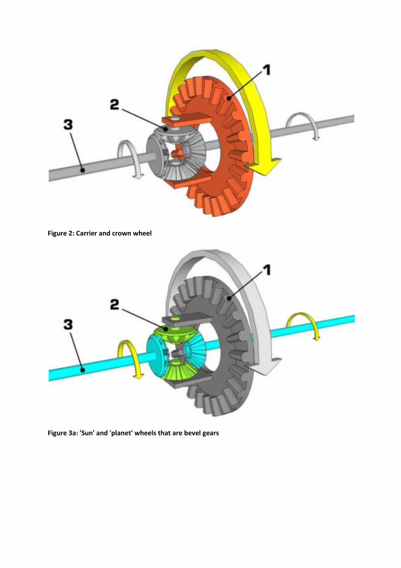
Torque is supplied from the engine, via the transmission, to a drive shaft, which runs to the final drive unit that contains the differential. A spiral bevel pinion (fig.1) takes its drive from the end of the propeller shaft, and is encased within the housing of the final drive unit. This meshes with the large spiral bevel ring gear, known as the crown wheel. The crown wheel and pinion may mesh in hypoid orientation. The crown wheel gear is attached to the differential carrier or cage (fig.2), which contains the 'sun' and 'planet' wheels or gears (fig.3a & 3b), which are a cluster of four opposed bevel gears in perpendicular plane, so each bevel gear meshes with two neighbours, and rotates counter to the third, that it faces and does not mesh with. The two sun wheel gears are aligned on the same axis as the crown wheel gear, and drive the axle half shafts connected to the vehicle's driven wheels (fig.4). The other two planet gears are aligned on a perpendicular axis which changes orientation with the ring gear's rotation.
Figure 3a: 'Sun' and 'planet' wheels that are bevel gears
The carrier (green) is held stationary while the sun gear (yellow) is used as input. The planet gears (blue) turn in a ratio determined by the number of teeth in each gear. Here, the ratio is -24/16, or -3/2; each planet gear turns at 3/2 the rate of the sun gear, in the opposite direction.
Figure 3a: 'Sun' and 'planet' wheels that are spur gears
Figure 4: Half shafts connected to the vehicle's driven wheels
Bevel gears are gears where the axes of the two shafts intersect and the tooth-bearing faces of the
gears themselves are conically shaped. Bevel gears are most often mounted on shafts that are 90
degrees apart, but can be designed to work at other angles as well. The pitch surface of bevel gears is
a cone.
Working
When power is applied from the engine, it travels from the driveshaft, into the spiral bevel pinion,
into the carrier via the ring gear. The carrier is the heart of the differential and houses the small
pinion gears (planet gears) that are held in place by a shaft. These gears allow the half shafts to
rotate at different speeds. When one axle rotates slowly, the other will compensate by rotating
faster. When a car is driving straight down the road, both drive wheels are spinning at the same
speed. The input spiral bevel pinion is turning the ring gear and cage, and none of the pinions within
the carrier are rotating(opposite the carrier): both side gears are effectively locked to the cage. (see
figure)
Figure: straight
When a car is driving straight down the road:
The input force is spread evenly over both axles (left right)
Torque: Τ1= Τ2
Resistance force left = resistance force right
Angular velocity: ω1= ω2 n1=n2
Power: Τ1 x ω1 = Τ2 x ω2 P1=P2 Flash bestand rechtdoor
As the car begins to turn the small pinions in the cage start to spin, allowing the wheels to move at
different speeds. The inside wheel spins slower than the cage, while the outside wheel spins faster.
(See figure)
Figure: turn (relative = relative to the carrier)
Flashbestand turn
When a car is turning:
The input force is spread evenly over both axles (left right)
Torque: Τ1= Τ2
Resistance force left > resistance force right
Angular velocity: ω1< ω2 n1<n2
Average(n1,n2) =ncrown wheel
Power: Τ1 x ω1 < Τ2 x ω2 P1<P2 Evidence of the average angular velocity Given: Angular Velocity of the crown wheel: ωcw
Ask: ωaverage Solution: Angular velocity of the half shafts relative to the carrier: ω1rel & ω2rel
If ω1 is the angular velocity of the inner wheel and ω2 is the angular velocity of the outer wheel ω1= ωcw + ω1rel ω2= ωcw + ω2rel And: ω2rel = - ω1rel = ω (in 3D!!!) ω1= ωcw - ω ω2= ωcw + ω ωaverage= 0.5 x (ω1 + ω2)= 0.5 (ωcw - ω + ωcw + ω) = 0.5 x 2ωcw = ωcw
As the differential carrier rotates, the changing axis orientation of the planet gears imparts the motion of the ring gear to the motion of the sun gears by pushing on them rather than turning against them (that is, the same teeth stay in the same mesh or contact position), but because the planet gears are not restricted from turning against each other, within that motion, the sun gears can counter-rotate relative to the ring gear and to each other under the same force (in which case the same teeth do not stay in contact).
Thus, for example, if the car is making a turn to the right, the main crown wheel may make 10 full rotations. During that time, the left wheel will make more rotations because it has further to travel, and the right wheel will make fewer rotations as it has less distance to travel. The sun gears (which drive the axle half-shafts) will rotate in opposite directions relative to the ring gear by, say, 2 full turns each (4 full turns relative to each other), resulting in the left wheel making 12 rotations, and the right wheel making 8 rotations.
The rotation of the crown wheel gear is always the average of the rotations of the side sun gears. This is why, if the driven roadwheels are lifted clear of the ground with the engine off, and the drive shaft is held (say leaving the transmission 'in gear', preventing the ring gear from turning inside the differential), manually rotating one driven roadwheel causes the opposite roadwheel to rotate in the opposite direction by the same amount.
When the vehicle is traveling in a straight line, there will be no differential movement of the planetary system of gears other than the minute movements necessary to compensate for slight differences in wheel diameter, undulations in the road (which make for a longer or shorter wheel path), etc.
A function of the differential was a also to act as the final gear reduction in the vehicle, slowing the rotational speed of the transmission on final time before it hits the wheels. This final gear reduction is carried by the bevel pinion and the crown wheel. When the pinion has 8 teeth and the crown wheel 32, there is are speed reduction of 25%.
Functional discription of the parts
The drive shaft: The drive shaft is the input shaft of the differential, it serve to transmit
driving torque from the transmission to the differential.
The bevel pinion and the crown wheel: They serve for the final gear reduction and to drive
the carrier that's intersect the driveshaft direction. Most of the time we use a SPIRAL bevel
pinion. This type of pinion can tolerate bigger forces because the contact area is greater.
The carrier: is connected with the planet gear and not with the sungear (half shafts).
The planet gears: connect the crown wheel (indirectly) with the bevel gears of the half shafts
(directly) so the half shafts can rotate at different speeds.
The bevel pinions of the half shafts: connects the half shafts with the planet gears.
The half shafts: transmitting the driving torque to the wheels.
(Bearings): to reduce friction.
The Case: To protect the differential mechanism. Mostly the case is filled with oil so the
friction between the gears is reduced and to improve the cooling.
Differentials and traction
One undesirable side effect of a open differential is that it can limit traction under less than ideal conditions. The amount of traction required to propel the vehicle at any given moment depends on the load at that instant—how heavy the vehicle is, how much drag and friction there is, the gradient of the road, the vehicle's momentum, and so on.
The torque applied to each driving wheel is a result of the engine, transmission and drive axles applying a twisting force against the resistance of the traction at that road wheel. Unless the load is exceptionally high, the drivetrain can usually supply as much torque as necessary, so the limiting factor is usually the traction under each wheel. It is therefore convenient to define traction as the amount of torque that can be generated between the tire and the road surface, before the wheel starts to slip. If the torque applied to drive
wheels does not exceed the threshold of traction, the vehicle will be propelled in the desired direction; if not, then one or more wheels will simply spin.
To illustrate how a open differential can limit torque applied to the driving wheels, imagine a simple rear-wheel drive vehicle, with one rear road wheel on asphalt with good grip, and the other on a patch of slippery ice. With the load, gradient, etc. The vehicle requires a certain amount of torque applied to the drive wheels to move forward. If the two road wheels were driven without a differential, each road wheel would be supplied with an equal amount of torque, and would push against the road surface as hard as possible. The road wheel on ice would quickly reach the limit of traction, but would be unable to spin because the other road wheel has good traction. The traction of the asphalt plus the small extra traction from the ice exceeds the minimum requirement, so the vehicle will be propelled forward.
With an open differential, however, as soon as the "ice wheel" exceeds the threshold of traction available, it will start to spin; this will further reduce traction at that wheel as the amount of torque required to spin the wheel against traction lowers after the threshold is initially broken. Since an open differential limits total torque applied to both drive wheels to the amount utilized by the lower traction wheel multiplied by a factor of 2, when one wheel is on a slippery surface, the total torque applied to the driving wheels will be lower than the minimum torque required for vehicle propulsion. Thus, the vehicle will not be propelled.
Many newer vehicles feature traction control, which partially mitigates the poor traction characteristics of an open differential by using the anti-lock braking system to limit or stop the slippage of the low traction wheel, thus transferring more torque to the wheel with good traction.
The limited slip differential
Open differentials might get you into trouble when you are driving off-road. If you have a
four-wheel drive truck, or an SUV, with an open differential on both the front and the back,
you could get stuck. because the open differential always applies the same torque to both
wheels. If one of the front tires and one of the back tires comes off the ground, they will just
spin helplessly in the air, and you won't be able to move at all. The solution to the problems
above is the limited slip differential (LSD). Limited slip differentials use various mechanisms
to allow normal differential action when going around turns. When a wheel slips, they allow
more torque to be transferred to non-slipping wheels.
The Differential lock
A differential lock using differential gears in normal use but using air or electrically controlled mechanical system, which when locked allow no difference in speed between the two wheels on the axle. They employ a mechanism for allowing the axles to be locked relative to each other, causing both wheels to turn at the same speed regardless of which has more traction; this is equivalent to effectively bypassing the differential gears entirely. The differential lock = 100% limited slip differential = "Zuivere Sperdifferentieel"