Vertical Interface Methodology for Connecting Constructive and Virtual Level Simulations Roger D. Smith Student Id#: 8048 Dissertation submitted in partial fulfillment of the requirements for the degree of Doctor of Philosophy in Computer Science Century University 2155 Louisiana Boulevard, NE Suite 8600 Albuquerque, NM 87110-5401 September 15, 1994
Transcript
Vertical Interface Methodology forConnecting Constructive and Virtual Level Simulations
Roger D. Smith
Student Id#: 8048
Dissertationsubmitted in partial fulfillment
of the requirements for the degree ofDoctor of Philosophyin Computer Science
Century University2155 Louisiana Boulevard, NE
Suite 8600Albuquerque, NM 87110-5401
September 15, 1994
ii
c 1994Roger D. Smith
All Rights Reserved
iii
The Dissertation
of
Roger D. Smith
is approved, and is acceptable
in content, quality, and form.
________Charles Jimminez, PhD______
________Lawrence Paullson, PhD_____
________Thomas A Burgess, PhD_____Faculty Advisor
Century University2155 Louisiana Boulevard, NE
Suite 8600Albuquerque, NM 87110-5401
September 15, 1994
iv
Acknowledgements
It is appropriate that Dr. Thomas Burgess be acknowledged in this paper for his services asFaculty Advisor and mentor. Without Dr. Burgess's advice and contribution, this paper mightnot have been possible.
Note on Electronic VersionThe figures published in the original version of this dissertation were not captured in a digitalformat that could be included in this document. Unfortunately, blank spaces are found wherethese figures reside in the printed version.
v
Roger D. SmithSeptember 15, 1994
Vertical Interface Methodology forConnecting Constructive and Virtual Level Simulations
Abstract
The United States Department of Defense has invested heavily in computer simulations sinceWorld War II. As a result, simulations and models exist to replicate or evaluate most combatsystems and situations. One large class of simulations consists of those used for trainingpersonnel to perform their operations more successfully. These are recognized by the generalpublic as "war games" and "flight simulators".
As training simulations evolved, a natural dichotomy of functionality and interface emergedwhich lead to major differences between: Constructive, Virtual, and Live simulation. Horizontal and vertical interfacing of these classes of simulation is an important step in thefuture development of training systems. It is also seen as a means of decreasing the cost offuture development. Rather than creating multiple models of the same function, as has beendone in the past, it will be possible to create one which complies with the interface standards. This will then operate in conjunction with any other model which also meets these interfacestandards.
In this paper, we will explore methods for integrating constructive and virtual level simulations. The virtual community is beginning to develop semi-automated forces (SAFOR) algorithmswhich will allow them to join with constructive simulations. Enhanced versions of SAFORwill be the bridge that connects the constructive and virtual worlds. These will perform thefidelity enhancement and removal needed for two-way communications across the verticalbridge.
The simple broadcast backbone networks used in both the constructive and virtual communitieswill not support the types of exercises envisioned for the military. A more complex structuremust be imposed on the network, something similar to the Internet. Each node will simulateevents in a specified geographic area. Within a node or LAN, these areas may be furthersubdivided into a military command structure.
vi
Table of Contents
1 Introduction................................................................................................................................. 11.1 Background................................................................................................................. 11.2 Origin of the Models................................................................................................... 3
1.2.1 Constructive Simulations............................................................................ 41.2.2 Virtual Simulators........................................................................................ 51.2.3 Live Simulation........................................................................................... 6
1.3 Interoperability............................................................................................................ 61.4 Enabling Technologies................................................................................................ 81.5 Contribution of this Work........................................................................................... 91.6 Dissertation Organization.......................................................................................... 11
2 Review of Literature and Earlier Work..................................................................................... 122.1 Incorporation of Models within Simulations............................................................ 132.2 Independent Processes on a Single Machine............................................................. 172.3 Simulations with Distributed Components............................................................... 20
2.3.1 Local Area Networks.................................................................................. 202.3.2 Wide Area Networks.................................................................................. 22
2.4 Dedicated Horizontal Interfaces................................................................................ 272.4.1 CBS - AWSIM Interface............................................................................ 282.4.2 CBS - CSSTSS Interface............................................................................ 302.4.3 CBS - TACSIM Interface........................................................................... 30
Figure 1-1. Three Categories of DoD Simulation......................................................................... 2Figure 1-2. Conceptual Architecture for a Vertically Integrated Training Simulation................. 2Figure 1-3. One View of Relationships Between the Different Simulation Levels..................... 7Figure 1-4. ALSP/DIS Conceptual Interface................................................................................ 9Figure 1-5. Vertical Integration Tasks.......................................................................................... 10Figure 1-6. Interface Organizational Architecture....................................................................... 11Figure 2-1. Interoperability Evolution Tree................................................................................. 13Figure 2-2. Integration of High Fidelity Model........................................................................... 16Figure 2-3. Database Oriented Simulation Structure................................................................... 18Figure 2-4. Training Simulation Operational Environment........................................................ 20Figure 2-5. Simulation WAN....................................................................................................... 22Figure 2-6. Simulation Data Packet............................................................................................. 23Figure 2-7. CBS Workstation Connections.................................................................................. 24Figure 2-8. TACSIM-TALON Integration................................................................................... 25Figure 2-9. RPC Structure............................................................................................................ 27Figure 2-10. Logical Processes in Parallel Simulation................................................................ 32Figure 2-11. Aggregate Level Simulation Protocol Design......................................................... 37Figure 2-12. DIS Architecture...................................................................................................... 42Figure 2-13. DIS Functional Requirements................................................................................. 43Figure 2-14. DIS PDU Requirements.......................................................................................... 44Figure 2-15. DIS Protocol Data Unit........................................................................................... 45Figure 2-16. DIS Programs........................................................................................................... 46Figure 2-17. Physical DIS Network Interface.............................................................................. 46Figure 2-18. DIS Gateways.......................................................................................................... 47Figure 2-19. DIS Network Performance Analysis....................................................................... 47Figure 2-20. Virtual Body Coordinate System............................................................................. 48Figure 2-21. DIS Connections to Live Equipment...................................................................... 49Figure 2-22. ModSAF Development Timeline............................................................................ 52Figure 2-23. ModSAF Components............................................................................................. 53Figure 2-24. ModSAF Model Libraries....................................................................................... 54Figure 2-25. AWSIM to ModSAF Functionality......................................................................... 56Figure 2-26. JPL Project Alpha Links.......................................................................................... 58Figure 2-27. Eagle to BDS-D Functionality................................................................................ 59Figure 2-28. Eagle to IST SAFOR Gateways.............................................................................. 60Figure 2-29. BBS to SIMNET Connections................................................................................ 62Figure 2-30. BBS to SIMNET Functionality............................................................................... 65Figure 3-1. Constructive-Virtual Unit Relationships................................................................... 67Figure 3-2. Simple Unit Movement............................................................................................. 71Figure 3-3. Complex Unit Movement.......................................................................................... 73Figure 3-4. Simple Unit Detection............................................................................................... 73Figure 3-5. Layers of Disaggregation........................................................................................... 80Figure 3-6. CBS-TACSIM Disaggregation Template.................................................................. 80
x
Figure 3-7. Interaction of Objective and Environment................................................................ 84Figure 4-1. Model Level............................................................................................................... 90Figure 4-2. Military Unit Level.................................................................................................... 91Figure 4-3. Military Command Level.......................................................................................... 92Figure 4-4. Operational Level...................................................................................................... 92Figure 4-5. Geographic Areas...................................................................................................... 93
1
Chapter 1
Introduction
1.1 Background
The United States Department of Defense has invested heavily in computer simulations sinceWorld War II. As a result, simulations and models exist to replicate or evaluate most combatsystems and situations. One large class of simulations consists of those used for trainingpersonnel to perform their operations more successfully. These are recognized by the generalpublic as "war games" and "flight simulators".
As training simulations evolved, a natural dichotomy of functionality and interface emergedwhich lead to major differences between:
Constructive Level (war games),
Virtual Level (flight simulators), and
Live (target and flight ranges)
2
simulation (Figure 1-1) [Singley, 1993]. After nearly 40 years of progress, these threesub-communities have grown so far apart that they do not and can not interoperate. As a result,
each group can not take advantage of the progress made by the other two, often resulting induplicated work.
Figure 1-1. Three Categories of DoD Simulation
3
Horizontal and vertical interfacing is seen as an important step in the future development ofmilitary simulations. Many benefits ensue. It will be possible to create a more complete andaccurate environment in which to train our defense forces by joining these together. It is alsoseen as a means of decreasing the cost of future development. Rather than creating multiplemodels of the same function, as has been done in the past, it will be possible to create onewhich complies with the interface standards. This will then operate in conjunction with any
other model which also meets these interface standards (Figure 1-2).
The 1991 Defense Science Board studied the problem of the lack of interoperability betweenthese communities and between different simulators within each community [DMSO, 1993].Their recommendation was that projects be initiated to link all simulations and allow them toparticipate together in a single simulation environment. In response, the Virtual Levelcommunity created the Distributed Interactive Simulation project (DIS). The Constructive Levelcommunity created the Aggregate Level Simulation Protocol project (ALSP).
The Live simulation community faces a much more difficult task. Their simulators are actuallythe aircraft and vehicles of war. Interfacing these requires a built-in simulation mode which canbe switched on when engaged in an exercise, and off when engaged in actual operations. Theseideas are being included in new procurements, but some equipment can currently be interfacedwith simulations due to the design of the simulation. The intent in the Live world is to use theDIS standards. Hence, solving the ALSP to DIS mergence problem will provide a large measure
Figure 1-2. Conceptual Architecture for a Vertically Integrated Training Simulation
4
of the connection needed to include the Live community.
Both the ALSP and DIS projects have made serious progress within their own environs, buthave made little effort to join with one another. The number of problems to be solved by eachproject is so vast, the impact so far reaching, and man-power so limited, that it is difficult tointerest either community in this vertical integration task. However, the Department of Defensehas continued to emphasize its interest in integrating all simulations, regardless of their level offidelity. As a result, a few projects are underway to bridge this gap. These researchers havebegun by addressing minor problems and attempting to demonstrate special case integration,rather than completing the entire vertical integration project at once.
1.2 Origin of the Models
Now that the government is so focused on connectivity, it is easy to criticize earlier models fornot catering to this need. But, an understanding of the origin and mission of existing modelswill be helpful in understanding their capabilities and future needs.
Wargaming is an ancient art. As long as there have been organized wars there has been someform of wargaming. Drawing in the sand and moving stones as forces against the enemy mayhave been the beginning. Originally used to plan an attack, the techniques became a means ofre-telling a battle and then a form of training. Playing out a war in the sand with markersrepresenting friendly and enemy forces was used to teach lessons learned in past battles. It alsobecame a means of exploring "what if" scenarios; enabling visualization of tactics and invitingreactions from others.
During the Roman era, wargaming was formalized into "sand tables" and unit icons. A largesand box was landscaped into a representation of the field of battle. Trees, hills, boulders, cliffs,rivers, and swamps were all represented. Military forces were simulated with wooden or stonecarvings of men, horses, and tents. Two commanders could then face each other across the sandand explore the possible outcomes of planned tactics. As a training tool this was, and still is,invaluable. In fact, modern sand tables that fill entire gymnasiums can be found in use by theArmy in places like Fort Leavenworth, Kansas and Fort Hood, Texas. While soldiers may trainwith their weapons in drills, commanders use wargames to exercise their primary weapon - themind.
1.2.1 Constructive Simulations
There are hundreds of models within the constructive community. These are usually referred toas constructive models, since individual objects (tanks, helicopters, etc.) are grouped intooperational constructs such as armor companies and air defense batteries. In this paper we limitourselves to the most widely used and accepted of these. Hundreds of models exist becauseanalysts with a problem to solve often construct a unique model of it, complete their study, thenput it aside until it is needed again. There has also been a tendency for projects to build theirown new models, rather than adapting one built by others. The largest and most widely accepted
5
of these are:
Corps Battle Simulation (CBS) - This model is used to train the decision making abilities ofcorps, division, and battalion commanders. It focuses on troop movement, attrition, artilleryfire, and follow-on-force employment.
Brigade/Battalion Simulation (BBS) - This model is a smaller scale model following in thefootsteps of CBS, but meant specifically for battalion commanders.
Air Warfare Simulation (AWSIM) - This model is used by the US and NATO Air Forces totrain wing and squadron commanders in the employment of their air assets. It focuses onair-to-air, air-to-surface, and surface-to-air combat. It models air movement, attrition, electronicwarfare, air refueling, ground strikes, and the response against these aircraft by surface-to-airmissiles.
Tactical Simulation System (TACSIM) - This model simulates the performance of divisionand theater intelligence collection assets. It is meant to train the intelligence analysts thatprovide enemy situation maps to the combat commanders.
Joint Electronic Combat / Electronic Warfare Simulation (JECEWSI) - This modelfocuses on the electronic warfare environment. It includes the use of air- and ground-basedradio frequency (RF) jammers, and radar collection and detection.
Combat Service Support Training Simulation System (CSSTSS) - This models the use ofthe logistic capabilities to provide supplies to forces in combat. Supplies modeled includeammunition, missiles, food, fuel - almost everything necessary to equip and maintain an army incombat.
Battle Intelligence Collection Model (BICM) - This is an intelligence collection model meantto bypass the intelligence analysts and provide enemy situations in an analyzed form directly tothe combat commanders.
Aggregate Level Simulation Protocol (ALSP) - This is a family of software and com-munication protocols which join all of the above models into a loose confederation, operatingtogether.
Before the advent of ALSP, models were connected on a one-to-one basis. When it becamenecessary to connect the air and ground war, an interface was built to transfer data between CBSand AWSIM. This interface was designed with one mission in mind and no thought given togenerality or reuse. Therefore, the software could only be used for this one connection. Thetrend having been set, other interfaces were soon needed to bring the strengths of each modelinto a single exercise environment. Interfaces were soon built between CBS-TACSIM,CBS-JECEWSI, CBS-BICM, etc.
Once the benefits of this type of distributed modeling were experienced, it became desirable toconstruct a generic interface standard which could be used for all current and future models.
6
This emerged as ALSP.
1.2.2 Virtual Simulators
Interfacing at the Virtual level emerged a bit differently. Simulators of fighter aircraft andarmored vehicles were developed to train the equipment operators without actually using theequipment. This soon spread to commercial aircraft and industrial vehicles. The first large scaleintegration project was sponsored by the Defense Advanced Research Projects Agency(DARPA). A group of tank simulators were joined to form a family known as the SimulatorNetworking (SIMNET) project. This soon became renowned for its ability to immerse multiplepeople and teams in a single virtual combat environment. Tank crews were able to fight againsteach other, even to the point of firing their weapons, without risking each other's lives.Following this success, DARPA (now ARPA) undertook to include flight simulators,helicopters, armored vehicles, and even infantry into this virtual environment. This project isthe Distributed Interactive Simulation (DIS). The focus is much the same as ALSP, but at thevirtual level.
On the DIS side, SIMNET is being replaced with ever more complicated simulators under theArmy's Combined Arms Tactical Trainer (CATT) program. These along with a host of existingVirtual level simulations, will make up the DIS network. The CATT program includes:
Close Combat Tactical Trainer (CCTT) - This is the direct follow-on to SIMNET. Itreplicates the functions of armored and mechanized vehicles such as the M1A1 tank, M1A2tank, and the Bradley Fighting Vehicle.
Aviation CATT (AVCATT) - This will replicate Army air assets, primarily Apache and CobraAttack helicopters.
Air Defense CATT (ADCATT) - Simulates the performance of air defense batteries such asthe Patriot.
Field Artillery CATT (FACATT) - Simulates operations of 155mm artillery and MultipleLaunch Rocket Systems (MLRS).
Engineering CATT (ENCATT) - Simulates the operations of engineering vehicles such asmine layers/removers, bulldozers, and bridging equipment.
These simulators will be tested under a program known as Battlefield Distributed Simulation -Developmental (BDS-D). The experiments will focus on operations: Line-of-sight Anti-tank(LOSAT), Command Ground Station (CGS), Combined Arms Command and Control (CAC2),Combat Identification (CID), and Rotorcraft Pilot's Associate (RPA). All of these focus ontesting the capabilities of the simulators to provide realistic, integrated training in the virtualenvironment [Singley, 1993].
1.2.3 Live Simulation
7
The third form of simulation identified by the 1991 Defense Science Board is Live Simulation.This is the operation of fighters in training exercises as popularized by movies such as "TopGun". Although operating the actual equipment the activity is a simulation in that it involvesstaged combat between the aircraft. Exercises are carried out by the Air Force in the "Red Flag"program, the Navy "Top Gun" program, the Army "Green Flag", and a host of others.
1.3 Interoperability
As computer and networking technology has matured the ability to replicate reality within themhas increased. We are now at a point where we can join thousands of these simulators into asingle environment and create events which are useful in a training sense, and valuable from aresearch point of view.
One major problem that has arisen is the fact that ALSP models update unit activities and statusevery 1 to 6 minutes, while DIS models do so every 100 to 300 milliseconds, a 1:600 difference[Smith, 1992 and The DIS Vision, 1993]. The difference is obviously due to the level of fidelityof object performance. A flight simulator pilot expects to see the terrain and other objects movepast him in real time. But the division commander is used to watching movement in terms ofhours. Obviously some bridge or translation mechanism is needed to remove details from thedata flowing up to ALSP and add it to data flowing down to DIS.
Figure 1-3. One View of Relationships Between the Different Simulation Levels
8
One bridge has evolved from a project designed to provide automated but reactive opponents inthe DIS world. In a SIMNET exercise, there is a definite need for more friendly and enemyobjects than there are simulators and crews to man them. Without this, the virtual world consistsof a handful of tanks hunting each other. But, realism may require hundreds or thousands ofvehicles all engaged in independent war fighting activities. To provide this level of interaction,the SIMNET project developed the Semi-Automated Forces model (SAFOR). This isresponsible for creating intelligent, reactive, and realistic fighting forces to join with or fightagainst the tanks actually manned by human crews. Thus far, it has succeeded at only a verycrude level of realism, but it is the beginning of more advanced techniques. Generally, theconcept has been dubbed Computer Generated Forces (CGF) and is being pursued by severaldifferent offices (Figure 1-3).
Since Computer Generated Forces use state and event information to create a realistic force,they are performing some of the functionality needed to add fidelity to information flowingdown from ALSP to DIS. This is currently being explored as a bridging technique. By reversingthe process, CGF may also operate as a filter, removing details from data flowing from DIS toALSP.
Given that such bridges are necessary, we will explore the types of functions that must beincorporated into them. We plan to show which details in the DIS-world must cross into ALSP-space, and which do not. We will also show the effects of playing aggregated units in ALSP,while smaller parts of these are played as manned objects in the DIS-world.
9
1.4 Enabling Technologies
Earlier we referred to the recent advancements in technology which have made simulationpossible and desirable. Here we will briefly outline these technologies and their contributions.
Power. The first is the extreme improvement in computer processing power. The powerof early computers had a definite sizing effect on the simulations developed on them.Each model was seen as being the size of the host computer, usually a DEC VAX. Asdistributed computing has come to the forefront this limitation is being shattered.
Networking. Distribution via networking has seriously altered the mission of combatsimulations. Where CBS, TACSIM, etc., were originally used to train a local audience,they are now networked together and operate across the globe. In fact, it is not unusualfor the computer running a simulation in Germany to be physically located in Kansas.The Blue forces may be operating in tents in the fields outside small German villages,but their opponents are at the National Simulation Center, Fort Leavenworth, Kansas.Time zones and geography are irrelevant, as both groups are immersed in the simulatedevents inside the computer. At first, computers were joined in a Local Area Network inwhich the communication medium was a dedicated line wired between the computers.Later, Wide Area Networks where assembled, and then enhanced by the advent of fiberoptics and communications satellites.
Graphics. Graphics have had a profound impact on the utility of computer simulation.Early models operated with input and output in textual format. It was then up to thehumans to translate this into graphic form, usually as tactical maps of unit locations andterrain. Today, the computer also controls these displays and automatically updates themas the simulation progresses. Unfortunately, graphics have not been implemented as aninput form, as much as for output. This is primarily due to the difficulty in creating auser input interface which is quicker, more flexible, and more intuitive to use than akeyboard.
Modeling. The last advancement is the development of military combat simulation andmodeling techniques. These are noticed only by those in the industry, but they have beensignificant. Unit representation in TACSIM has enabled it to model the operations ofthousands of units, containing tens of thousands of objects on a very limited computerbudget. Monte Carlo modeling is a relatively new field. As with computers one of itsfirst proponents was John Von Neumann in the 1950's. The field developed quickly intothe 1980's, but is now experiencing a plateau, primarily due to the attention beingfocused on new computing technologies.
10
1.5 Contribution of this Work
We will attempt to explore and suggest some solutions to the vertical integration problem in thispaper. Specifically, we will be looking at methods for managing the changes in fidelity requiredby units at the constructive level and those at the virtual level. This must be done in anenvironment in which several models are interoperating at both levels. Therefore, the task goesbeyond a simple generic connection between two models. Interactions and information crosstalk must be considered (Figure 1-4). When one tank transfers its position up to the constructiveworld, it becomes more than a single message. The information must go to all constructivemodels concerned with the operation of the organizational unit owning that tank, which maynumber from one to one hundred. Therefore, all models of interaction must scale well,preferably O(log n).
Figure 1-4. ALSP/DIS Conceptual Interface
11
On the other hand, a method is needed for adding detail to unit commands flowing down intothe virtual level. Although an aggregated unit may be told to move from point A to point B in agenerally straight line, its virtual counterpart must translate this into a specific path throughdetailed terrain representations. It must also account for and react to any intervention byobstacles such as missing bridges and encounters with enemy units. The effects of these detailsmust then be reflected in the operations of the aggregated unit in the upper levels (Figure 1-5).
These problems are not trivial, which is one reason for the slow progress being made inconnecting the two worlds. But, neither is the task impossible. In the real world, thesetranslations are made constantly during wartime, where hundreds of human minds and bodiesare involved in the process which we intend to accomplish with a few computers.
Figure 1-5. Vertical Integration Tasks
12
If we are to separate the interface into functional parts, rather than use one large conduit, wemust select a method of organization. Several options are workable (Figure 1-6). Allinteractions with a given constructive level simulation may be assigned a communicationchannel and interface device. Grouping may be done at the organizational command level.Here, all information concerning units or objects belonging to an operational commandheadquarters use the same interface. Different types of unit operations may share an interfaceunit. Here, all movement messages use one conduit, resupply messages another, andengagement messages still another. Finally, information may be grouped geographically. Allmessages originating or destined for a certain area may be assigned the same interface channel.
All of these methods will be examined in this paper, along with the types of informationexchanged in the messages. Additionally, we will explore methods for translating theinformation so that it is appropriate to the level of the intended receiver.
Figure 1-6. Interface Organizational Architecture
13
1.6 Dissertation Organization
This dissertation is organized into five chapters. Chapter 1 is an the introduction to the problemand the current simulation community. Chapter 2 is a review of the simulation literature andearlier work that has been done on the vertical integration problem. Chapter 3 describes thetypes of translations that need to be performed on data traveling across the vertical bridge.These translations will be performed by interfacing models which are inserted between theALSP and DIS networks. Chapter 4 describes possible organizational architectures fortransmitting data between constructive and virtual simulations. This describes the functionalarchitecture for organizing data transfer. It does not discuss the physical connectivity needed tocarry the data. Chapter 5 provides a summary of the findings of the paper and recommendsavenues of future research on the vertical integration problem.
14
Chapter 2
Review of Literature and Earlier Work
Since vertical integration is in such an infant state, there is little literature available in the formof textbooks. Most information is in the form of conference proceedings and meetings betweensimulation proponents. These include semi-annual workshops on designing the DIS interface;quarterly meetings to design the ALSP interface; conversations between members of thecommunity; existing interfaces between specific simulations; annual conferences sponsored bythe Society for Computer Simulation, IEEE, and the Association for Computing Machinery;and, finally, electronic conferences on simulation.
This chapter will examine several of the existing and experimental methods for interfacingsimulations. These include:
Incorporation of Models within Simulations,Independent Processes on a Single Machine,Simulations with Distributed Components,Dedicated Horizontal Interfaces, Parallel Simulation Coordination,Aggregate Level Simulation Protocol,Distributed Interactive Simulation,Computer Generated Forces Models, andVertical Integration Prototypes.
15
The rest of this chapter will be devoted to exploring these nine interface types. Special attentionwill be given to the aspects of these which are pertinent to the topic of this dissertation. For thisreason, the sections are not exhaustive, more information on each can be found in the sourceslisted in the bibliography. The dynamic nature of the vertical prototypes insures that anyattempt to catalog their operations will necessarily be limited to the capability available at thetime of writing. All of these will have progressed by the time this dissertation is published. This paper attempts to make a contribution to the evolution of interoperability by exploringideas for vertical integration standards which will hopefully lead to full, seamless integration of
all simulations (Figure 2-1).
2.1 Incorporation of Models within Simulations
A basic method of simulation integration is accomplished by embedding one model insideanother. This is usually done by allowing a specialized, high-fidelity model of some sub-system
Figure 2-1. Interoperability Evolution Tree
16
of the larger system to handle all events pertaining to its area of expertise.
We shall explain this through the use of examples taken from the ALBAM simulation. ALBAM was built to simulate the entire theater of war. This includes events in direct-fireground combat, indirect-fire ground combat, logistics operations, combat engineering, groundand airborne electronic warfare, intelligence collection and dissemination, air-to-air combat,surface-to-air engagements, air-to-surface strikes, air-to-air refueling, airbase sortie generation,ground movement across terrain and via road networks, and all of the simulation management,input and output associated with these operations. Excluding the graphics displays and afteraction data collection, all of these functions are accomplished on a single computer using asingle global database [Smith, 1992].
Although the entire theater was replicated, certain areas were identified as highly significantoperations. In these cases, a finer level of detail was necessary than could be accomplished forthe entire model within the hardware, data, man-power, and schedule constraints. Enhancements were requested for the following areas:
To accommodate the first two on the list, detailed algorithms were incorporated into theALBAM model. But for the engagements, it was decided that existing specialized modelswould be integrated into the larger ALBAM model. The specialized models chosen for thesewere:
With an increase in fidelity comes an increase is CPU cost. Therefore, these improvements hadto be managed such that the entire ALBAM model was not adversely affected in its ability toprocess events in real-time. To accomplish this, two methods of integration were selected. TAC Thunder and TSAM would be used to generate multi-dimensional tables of theprobability-of-kill (Pk) for a given set of situations. This would be done for a wide range ofconditions, encompassing all events that would actually occur during an ALBAM simulation. Generating the tables was a massive undertaking involving hundreds of hours of planning andexecution time.
Under this method, when ALBAM determined that an air-to-air engagement was occurring, thevariables that govern the engagement were used as indices into the stored TAC Thunder tablesto acquire an appropriate Pk. The variables are not exactly those used to generate the tables. Inthese cases interpolation is done between the surrounding table values.
17
As an example, the variables provided by ALBAM for each side of the engagement may be:
Notice than a group of aircraft may carry more than one type of air-to-air missile. TAC Thunderis built to handle complex engagements between differing weapon types, simultaneously. Thisis a better method than generating multiple independent engagements for each type of missile,and then trying to introduce dependence in these events by adjusting the resulting probabilities.
The model would then operate on these variables as:
f [ R(CS, S, A, R, CM, Mi, Mj, ...) , B(CS, S, A, R, CM, Mi, Mj, ...) ] = Rk and BkRmix, Rmjx, . . .Bmix, Bmjx, . . .
where,
R(. . .) = Characteristics of Red/Enemy Aircraft Cell,B(. . .) = Characteristics of Blue/Friendly Aircraft Cell,
Rk = Aircraft Killed in Red Cell,Bk = Aircraft Killed in Blue Cell,Rmix = Red Missiles of Type i Expended,Rmjx = Red Missiles of Type j Expended,...Bmix = Blue Missiles of Type i Expended,Bmjx = Blue Missiles of Type j Expended,...
In the case of the TSAM model, the same method was used but the answer returned was aprobability of kill for aircraft in the cell. Monte Carlo methods are then used to determine theactual attrition experienced.
One fact should be obvious as we described the independent variables in the function above. Ahigh-fidelity model requires more detailed inputs in order to produce more accurate outputs. When models like TAC Thunder are run independently, the number of inputs is in the hundreds. These include variables such as cloud cover, wind speeds and directions, aircraft weight - both
18
fuel empty and fuel full, radar parameters, missile seeker-head characteristics, opening aspectangle, sun angle, etc. To join with a model such as ALBAM, these must be set to reasonablevalues and held constant through all replications used to generate the data tables. In doing this,certain assumptions must be made and recorded. The outcome of the air-to-air engagements arethen known to be accurate, subject to these assumptions.
In one sense, these assumptions weaken the fidelity of the TAC Thunder results. It is similar tofighting a battle by using historical texts to present examples similar to the combat situationcurrently experienced. The selected tactics may not be totally applicable, but the results aremore accurate than what could have been replicated without the text.
For the surface-to-air engagements, a different method was selected for integrating the JointMunitions Effectiveness Models (JMEM). In this case, translation software was built to preparethe variables (similar to those shown in the above example) for input directly into the models.The JMEM software had been integrated into the ALBAM executable binary. As with TACThunder, those variables not available had to be set to reasonable values. The computer thenexecuted the JMEM software and returned the results for application by ALBAM (Figure 2-2)
[General Dynamics, 1989].
This method does not require the storage space for the calculated tables, but it does increase thesize of the simulation software and executable binaries. It is slower than the table method, butprovides more accurate results since it does not have to resort to interpolation betweenpre-calculated values.
It should be pointed out that combat outcomes returned by the high-fidelity models to ALBAMneed not be applied directly to the target objects. These are still subject to interpretation ormodification within the larger model. In the case of ALBAM, a reliability factor was added to
Figure 2-2. Integration of High Fidelity Model
19
the air-to-surface Pk to produce a reduced kill-level on ALBAM targets. Similar factors areoften added for weapon/sensor counter measures and the existing electronic environment. These values represent characteristics not modeled in TAC Thunder or JMEM, and are usuallyderived from other models or actual combat data. The validity of combining these factors issomething that must be investigated. These bridge several data sources and produce a syntheticevent which more closely resembles a real-world encounter when applied correctly.
All of these methods indicate some of the steps that are taken to integrate models of differinglevels of fidelity, as will be the case between the ALSP and DIS communities.
2.2 Independent Processes on a Single Machine
Although early models were usually limited to a single process operating on a single machine,this paradigm soon gave way to more complex structures. The first step was to expand theoperations of the simulation to include multiple models operating on the same machine. Theadvantage of this on a single processor machine was not in achieving parallelism, but inallowing users' processes to appear to operate in parallel. The advantages of this in a multi-usersystem are to free the user from the task of waiting for one process to finish in order to executethe next, and to allocate more of the computer's total CPU cycles to the simulation, which nowappears as two independent customers on the machine. If these process were to share data,significant work had to be done to account for the lack of synchronicity between the processes. Once this was accomplished, the most common method for passing this data was to write to andread from files on disk.
The difficulties of operating simulations in this manner are very evident. The modeler mustspend much of his/her time overcoming the limitations of the computer's operating systemrather than designing and improving the models themselves. Also, simulations of this type donot allow for much human interaction. It was very difficult to input data at appropriate times ina dynamic manner. Since data sharing was done via disk files, human interaction with these canseriously delay or even corrupt the simulation runs. Therefore, this achievement of splitting themodel into several pieces was applicable where multiple runs of the simulation could operateindependently. But, the next step was to allow separate processes to access the same data poolsimultaneously. The primary method of accomplishing this was to create a "global memory"section accessible to any process which requested a mapping to it.
The creation of global or shared memory was very helpful in allowing the user to synchronizemultiple processes and observe the operations of the simulation. One process could now bedeveloped to read the shared memory and display its contents. Since files were not beingaccessed, such processes interfered little with the operation of the models. An I/O process canthen allow the operator to play an interactive part in directing the progress of the simulation.
Many models, both simple and complex, were, and are, developed under this structure. Simulations, such as the Air Land Battle Assessment Model, the Tactical Simulation, and theAir Warfare Simulation, operate in this mode today. All three of these are very complex,
20
capable of supporting dozens of users simultaneously. But, excepting the graphic displaydevices, all of the processes of the simulation are designed to operate on a single computer.
Communications among the different processes that make up the simulation is usually done bypassing messages into the global memory area. Each process is assigned locations to look forinput and to place output. These data exchange points are in many ways similar to the disk fileexchanges described earlier, though they do not suffer from many of the limitations.
In the case of the Air Land Battle Assessment Model (ALBAM), there is a single simulationprocess which focuses on a shared database (Figure 2-3). Events are scheduled by thesimulation itself or by any one of the many command input processes attached to user terminals. The users also have data output processes/terminals which display tables of informationconcerning the progress of the combat engagements being generated. Time synchronization isnot a problem since there is only one process determining time, and all the others simply acceptit and use it in their operations. The humans operating the simulation are synchronized withthis time by displays on their terminals, which they must accept as the current time. If this doesnot flow at the rate expected by the operators, it may cause disapproval, but they can not affectany change in it, nor can they cause the execution of events contradictory to the simulation time.
Originally, tabular combat data was plotted on maps by a host of clerks charged with the task. When a dynamic war was unfolding this method became very man-power intensive andinefficient. A natural alternative was to use graphic computers to automatically display this dataas it is known. These types of connections are discussed in one of the following sections.
Since the database is shared there is no need to pass messages between processes. Each processmay be responsible for extracting the information it needs and formatting it appropriately. Conversely, input processes are free to write information into the database, as specified in thedesign.
Models of this type are limited to the power of the CPU they are tied to. In turn, this is limitedby the state-of-the-art prevailing at the time of the computer's purchase. Although a simulationmay start small, it is common for additional features to be added until it taxes the capabilities ofthe machine. Therefore, all simulations are limited by the computer, rather than by the scope ofthe problem being solved. The model is not scalable.
Interfaces in this structure are purely via the data blackboard constructed in global memory. Allexchanges occur according to formats and rules laid out with an in-depth understanding of theoperations being performed and the order in which they are performed. Aside from the lack ofscalability, the system is limited in that modifications in the method or the order in which dataare stored must be done with a complete understanding of the system. Without this it ispossible, and probable, that the change will disrupt the operations of another part of the model,either directly or via a trickle-down effect.
22
2.3 Simulations with Distributed Components
Simulations with multiple processes appear to be natural candidates for distribution amongseveral computers. To accomplish this, hardware, software, and model connections need to beestablished to maintain the integrity of the simulated world. The connections of interest in thispaper are the modeling connections. In the examples above, ALBAM was designed to operatewith graphics computers producing maps of the locations and types of military units on thebattlefield (Figure 2-4). It also had a connection to another computer designed to extract datafor combat analysis. These systems presented a simple modeling interface. Both the graphicscomputers and the after action analysis computer were only reading the data being generated bythe simulation, input, and output processes. In this scenario there are no time or event
synchronization problems.
2.3.1 Local Area Networks
Graphics terminals have usually been output devices. As sophistication has grown, these arenow able to manipulate the graphics scene and filter the data being presented. But they stillenjoyed a one-way interface with the simulation process and its database. In this case, a fewsimple algorithms added to the simulation process can identify, extract, package, and transferthe data elements needed for the graphics display. Here, the coordination needed to capture aconsistent picture of the simulation data is a natural characteristic of the fact that the simulationmodels stop, while the graphics service routines capture and transfer their data packets [Smith,1992].
Given that a simulated entity, like a military unit, is assigned hundreds of characteristics, only
Figure 2-4. Training Simulation Operational Environment
23
those effecting the graphics images to be displayed are included in the data packets captured bythe service routines. Assume that a unit has the following characteristics:
Name,Size,Type,Location,Orientation,Velocity,Activity,Subordination,Future and Current Objectives,Historical Records,Combat Equipment Lists,Sensor Equipment Lists, andCommunications Equipment Lists.
To create a graphic representation of the unit may require only the fields: name, size, type,location, orientation, velocity, and activity. In most cases, the unit size and type will form anindex into a table of standard military symbols. These are placed according to the location field(which is actually short-hand for two or three coordinates). The symbol can then be annotatedwith the unit's name and iconic representations of velocity and orientation.
The graphics computer is actually a simulation of the visual representation of a military unit. Therefore, this is a crude, but efficient, vertical integration between a high fidelity simulation(ALBAM) and lower fidelity simulation (the graphic computer).
The same is true of the connection between the simulation model and the after action analysis(AAA) computer. In this case, the AAA may require quite a bit more of the characteristics ofthe simulated unit, but the method for acquiring and transferring this information may beexactly the same. In fact, the AAA system may add detail that is experienced, but not saved ororganized in the main simulation. AAA systems are typically concerned with the performanceof organizations and units through time. Since the AAA maintains a record of all collectedevents and statuses, it is in a position to know and synthesize data in the time domain. Thedriving simulation does not maintain this information. It is only aware of the state it is in rightnow, and has no memory of past events, though it does reflect the results of having experiencedthem. The simulated unit's strength may be down to 50%. The unit's data record contains noinformation as to how it arrived at this state, or even whether this state is its natural condition. Only the AAA system maintains these records and can demonstrate the events that led up to thepresent state.
We are not asserting that the main simulation could not have stored this information itself, onlythat it does not. The same situation exists when interfacing any two simulations. There is noreason that a constructive ground model could not maintain and track the locations of all of theequipment that has been "constructed" into a single unit record with a single location. But, thefact is that this type of information is not essential to the mission for which the model was built.
24
Therefore, these characteristics are handled by another model which does have such a mission. This separation of purpose is one of the driving factors behind the need for vertical simulationintegration.
2.3.2 Wide Area Networks
The Corps Battle Simulation (CBS) is used world-wide to create simulated trainingenvironments with which to improve the performance of military forces. Like ALBAM, itattempts to model all aspects of the battlefield at an acceptable level of detail. But, it hasextended the concept of distribution much further. Though the simulation model may berunning on a computer in Germany, users may interact with the model from terminals andcomputers in America, Korea, or France. (Figure 2-5). These players are usually equipped withcomputers which are responsible for providing a local copy of all data needed at that site.
The CBS core computer maintains the master copy of the database. This is then distributed to aprocess called the "Master Interface" (MI), which is responsible for brokering all data between
Figure 2-5. Simulation WAN
25
the core database and the remote databases. When the simulation moves or destroys units, itupdates its own database and informs the MI of the changes. The MI then updates its primarydatabase and begins the process of distributing the change to all of the distributed systems that itknows are interested. When the cycle is complete, all computers on the local and wide areanetwork contain their version of the data change first created by the CBS simulation model. This does not imply that all of the databases are identical. The MI understands exactly whichremote systems are interested in which types of data and distributes only that information to thesite. This reduces the amount of traffic on the networks, and reduces the filtering that must bedone by the remote systems to locate the data of interest [CBS Executive Overview, 1993].
To transmit this information, the MI creates data packets in a specified format. Upon receipt,these are then translated by the receiving system and the data stored or processed according tothe local software's instructions. A sample of one of these packets is shown in Figure 2-6. Thisis a common representation used for data packets in networking texts. It begins by identifyingthe type of data that will be found in the packet; followed by the intended receiver and sender ofthe information; the body which contains the actual data to be shared; and closes with a trailerindicating that the end of the packet has been reached. We point this out, because this sameconcept is being heralded as a great advantage of the new Distributed Interactive Simulation
(DIS) protocols, which we will examine a little later.
Figure 2-6. Simulation Data Packet
26
The organizational structure between CBS, the MI, and the distributed operations stations canbe drawn as in Figure 2-7. This type of organization is very effective, in fact it is being imitatedin current experiments to connect the constructive BBS and the virtual SIMNET simulations. One beauty of this system is that all interactive and scheduled data requests are handled by theMI. This leaves the CBS model free to spend the lion's share of its time processing simulationevents. It's entire connection to the outside world is the MI. Servicing only one customer andaccepting no interactive data requests eliminates many possibilities for slowing the system.
The Tactical Intelligence Simulation (TACSIM) is attached to several remote components. Oneof these, the TACSIM Analysis Operations Node (TALON), receives all reports produced byTACSIM; analyzes them; and produces a summary report which is then returned to TACSIMfor dissemination (Figure 2-8). TALON receives the output of TACSIM, making it similar tothe graphics terminal, which is only a receiver. TALON also returns reports to TACSIM for
Figure 2-7. CBS Workstation Connections
Figure 2-8. TACSIM-TALON Integration
27
delivery to the users. This extends the system to a two-way flow of information. TALON usesthe game time provided by TACSIM to insure that its operations are synchronized with those ofthe core simulation. In fact this game-time is often not determined by TACSIM, but is passedfrom CBS to TACSIM. Under this configuration, time flows forward, and it flows physically(as data packets) from simulation to simulation. The interfaces create a chain in which eachsimulation is one time step behind the link in front of it [TALON, 1994].
Model: CBS -> TACSIM -> TALONTime: t t-
�
t t-2*�
t
where, �
t = size of the time step.
This configuration does not disrupt the operations of these aggregate simulations because:
Each operates independently of the others,The confederation is stimulating humans thinking in terms of hours,Computer processing speeds prevent lag behind the set time differences.
If we were connecting CBS or TACSIM to a virtual-level simulation, much of the same reason-ing could apply. But, if this chaining effect were to be extended through 100 or 500 simulators,it would no longer be acceptable. A virtual simulator's position in the chain would dictate thetime it experienced, and another object, physically next to it, may be experiencing events asmuch as 100 time steps in the future. This interface technique does not scale.
The above interface technique has been used successfully for years to connect 2 to 6constructive simulations. The time lags at these levels are insignificant when compared to themission of training combat commanders. These commanders are used to having their situationmaps and report boards updated hourly. Therefore, the effect of a six minute lag between twosimulators is lost in the noise.
We mentioned that TALON analyzes TACSIM reports and produces a summary. This is a formof fidelity conversion. Details in TACSIM data are condensed into the significant events whichare of interest to participants at a higher level of aggregation. TALON adds a level ofaggregation and allows the human participants to eliminate the people that formerly performedthose operations.
The simulation must retain the accuracy of the TACSIM data input, but must reduce the volumeby a factor of 100. Since TACSIM is an intelligence collection model, the data given toTALON represents one side's perception of the enemy. To aid TALON in analyzing thisinformation, it is given access to the true information about the units being detected. With bothpieces of data it can then appear to make deductions as its human counterpart would, butwithout having to resort to the field of artificial intelligence. It is more akin to an expert system- given certain inputs, what would humans have decided about the data.
The processing done by TALON is similar to that which must be done when data is passed froma virtual level simulation to a constructive simulation. Many of the details need to be washed
28
out without losing the thread that is of interest in the aggregate world. To do this, the items ofaggregate interest must first be identified. Then a mapping can be done from all object data tothese interest items, with some information being ignored. As an example, TALON summariesconsist of the following data items:
UnitName,Location,Orientation,Activity,Affiliation,Time of State,Size, andType.
TACSIM, on the other hand, produces much more detailed information: the radar characteristicsof specific objects on the battlefield; the arrangement of individual pieces of equipment; and thecommand structure between several units. Filtering this down to the TALON level requires theomission of details.
The TACSIM-TALON interface is a special case of data flowing from a virtual level simulationto a constructive simulation. We state this even though TACSIM and TALON are bothconsidered constructive simulations. Actually, TACSIM just operates at a lesser degree ofaggregation than TALON. Dividing simulations into the three categories - Constructive(Aggregate), Virtual (Object), and Live - creates a simple frame of reference. But, it alsocategorizes simulations more strictly than is naturally true.
Connecting TALON to TACSIM is done via a networking technique known as remoteprocedure calls (RPC). These allow an application to be written as if all of its components areoperating on the local machine, though they actually span a network. The communicationutilities are hidden from the system developer and user. The structure of RPC is shown inFigure 2-9. This technique is extremely useful when a distributed simulation requires that you
Figure 2-9. RPC Structure
29
communicate with remote components as easily as with local [Shirley, 1994].
RPC is part of a larger technique known as client/server programming. A server is assigned thetask of processing requests for information and sending the results to the requester. Therequester is known an a client because it comes to the server asking for assistance, much likegoing to a lawyer or accountant for services. The client requests, the server complies. A servermay receive requests from any number of clients on any number of network nodes. On the ever-popular Internet, most of the services are established using this technique. Theability to access another computer and download files to a local computer is known as "ftp" (filetransfer protocol). It appears to the user that he has accessed the remote computer and isexploring its contents. Actually each command is being brokered between the local ftp clientand the remote ftp server. Each command entered is interpreted and transmitted to the remotecomputer. The appropriate response is then transmitted back to the local client where it isdisplayed, providing the appearance of being "logged in" to the remote computer. The loginprocess was simply a security check to insure that the client had permission to access the serverapplication. Other client/server applications include: finger, telnet, gopher, WAIS, WWW, andarchie. When simulations become distributed widely these same techniques must be used toverify permissions, provide timely responses, and hide the distinction between remote and localservices.
2.4 Dedicated Horizontal Interfaces
Although interfacing all simulations is a new effort in DoD, limited interfaces have been built inthe past. These have usually consisted of software and networks developed jointly by twomodel proponents to meet their interfacing needs. These interfaces operate only between thetwo target simulations, and are not able to connect others into a loose confederation. Uniqueinterfaces exist between CBS and TACSIM, CBS and AWSIM, CBS and CSSTSS, CBS andRESA, TACSIM and GRWSIM, and others. Although the software can not be reused, thetechniques and lessons learned are valuable.
2.4.1 CBS - AWSIM Interface
With CBS handling the ground warfare and AWSIM handling the air warfare during anexercise, the interface between them is an excellent example of the type of two-waycommunication and sharing of control that can be useful in a generic vertical integration. Oneof the basic concepts used in this interface is the idea of "ghosting". A ghost is an entity in onesimulation that is in no way controlled by that simulation. It may appear or disappear, withoutany cause, from the local simulation. An excellent example of a ghost unit is a flight of fighteraircraft being flown and controlled by AWSIM. The air model determines when and what typeof aircraft will be launched from an air base. Once airborne, these are controlled by pre-loadedor interactive commands directing them on their mission. Once the mission is complete, theseaircraft return to the air base and lose their unique identity as they return to the inventory of theair base.
30
While airborne, these aircraft are subject to attack by enemy aircraft and by ground-based airdefense systems, including surface-to-air missiles (SAMs) and anti-aircraft artillery (AAA). SAMs are modeled in AWSIM, and engage the aircraft as a natural component of the model. But, AAA assets are usually controlled by ground units only in CBS. If the aircraft do notappear in CBS, there is no way for the AAA to impact the outcome of the war [ALSP, 1993].
To create a target for the AAA, the AWSIM aircraft were ghosted in the CBS model. Theyappear from nowhere upon launch and disappear upon landing. During their mission, the ghostmay be detected and fired on by the CBS AAA assets. But, since the aircraft are ghosts theycan not be hit in CBS. Instead the engagement event is sent to AWSIM to determine theoutcome. In a sense, the AAA fire is then a ghost in AWSIM, appearing from nowhere andcausing events. When AWSIM receives the AAA event message, it uses its native algorithmsand response surfaces to determine which, if any, aircraft are killed. Those that are killed arethen removed from the AWSIM model, just as if they had been killed by a local SAM battery. A message is then generated and sent to CBS so the same results will be reflected in the ghost.
In a typical battle, many different interactions can occur between CBS-controlled and AWSIM-controlled entities. Each of these is handled in a similar way, allowing interaction betweenmodels, but maintaining their basic independence. The table below illustrates the ghosting thatoccurs to allow these interactions [CBS-AWSIM, 1993].
CBS AWSIMGhost Fixed Wing AircraftRotary Wing Aircraft GhostSHORAD NoneHIMAD HIMADALLRAD ALLRADAcquisition Radar GhostGhost AirliftNone Air Bases
With this list, we define the points at which interaction can take place between the two models. Fixed Wing Aircraft and SHORAD (Short Range Air Defense) were described in the example. There is no need to ghost SHORAD into AWSIM because the targets they are looking for arebrought into CBS for them. This same idea defines the interface for helicopters and acquisitionradar.
AWSIM air bases are not represented in CBS. But, in real world conflict helicopters may landat air bases to receive fuel and weapons. To enable this capability, CBS has agreed to place aForward Area Rearming and Refueling Point (FARRP) at each air base location. Both items arefixed and thus simulate the use of air bases by helicopters.
The modeling of HIMAD (High and Medium Range Air Defense) assets is a combination of theghosting and joint location techniques. The asset actually appears and can be controlled in bothsimulations. But it has different operational characteristics in each. To AWSIM, HIMADassets are seen as missile emplacements which can be fired, replenished, turned on and off, and
31
be destroyed. To CBS, HIMAD assets appear as ground vehicles which can move and bedestroyed. In this sense, CBS owns the wheels and drivers, while AWSIM owns the missilesand fire-controllers. When CBS moves its portion, the AWSIM portion moves with it. WhenAWSIM fires missiles, CBS loses these supplies. When the AWSIM HIMAD is bombed, boththe top and bottom of the asset are destroyed. When the CBS asset is destroyed by artillery fire,both pieces are destroyed. When the HIMAD runs out of missiles, these are resupplied by CBS. A message passed to AWSIM then replenishes them in that model where they are actually used.
The HIMAD assets seem to be more fully integrated than other assets. This is not true. Thenature of the asset calls for a two-part rendering, where the nature of the other assets does notrequire this level of interaction.
The ALLRAD (All Range Air Defense) assets are modeled in CBS as SHORAD, and inAWSIM as HIMAD. They are then toggled between looking for targets in CBS or in AWSIM. The theory is that, although capable of shooting at all targets, each is actually assigned a missionwhich dictates where it will operate. Changing this mission transfers control of the asset fromone model to the other.
The CBS model may mix air defense asset types that are contained within a unit. AWSIMallows only one type of air defense asset per unit. To join the two, CBS agreed to place onlyone type of missile in each unit joined with AWSIM. This type of limitation is indicative of theproblems that can occur as we explore a generic interface between many models.
32
2.4.2 CBS - CSSTSS Interface
The interface between CBS and CSSTSS resembles that between CBS and AWSIM, in thetechniques employed. The Combat Support Services Training Simulation System (CSSTSS) isa very high fidelity model of the mission performed by logistics assets. It is responsible forresupply and maintenance missions. When we mentioned above that CBS resupplies themissiles used by AWSIM, this assumed that CSSTSS was not also operating in the exercise. Ifit were, the mission would actually be controlled by CSSTSS, but the results would be the samefrom AWSIM's point of view [CBS-CSSTSS, 1993].
When CBS realizes that a unit needs to be resupplied, it sends a request to the supply unitassigned to it. This message, containing a list of the needed equipment, food, fuel, etc., is thenpassed on to CSSTSS which is responsible for acting on it. CSSTSS prepares the logisticspackage and loads it on the delivery trucks. These trucks are subject to repair and maintenanceschedules in CSSTSS. Therefore, although they exist, a delay may occur until they are readyfor operations. Once CSSTSS has determined that the assets can be placed in a convoy on theirway to the combat unit, a message is sent to CBS which generates the supply unit. CSSTSSdetermines the route that will be taken, the unit that will be serviced, the number and type oftrucks that will be used, and the time to load and unload the supplies. Once instantiated inCBS, this convoy of trucks is subject to its movement constraints and enemy assets. To CBS,the unit is just a convoy of trucks. The contents of these are only represented in CSSTSS.
If the convoy is attacked and destroyed, CBS relays the information to CSSTSS which thendetermines exactly which supplies were destroyed. When this convoy finally arrives at thecombat unit, it will contain a reduced amount of the requested materials. CSSTSS will thendetermine when these are actually unloaded and available for use by the CBS unit.
Should the convoy be obstructed such that delivery of the supplies is impossible, both modelsagree that the convoy will retrace its steps and return to the supply unit that generated it. Thisprevents missions from hanging in the simulations with no clear success or failure.
CSSTSS also controls the helicopters that are used to airlift combat units in CBS. In a sense,the CBS unit is then viewed as supplies for delivery. CSSTSS determines whether thehelicopters are available, based upon their flight histories and maintenance schedules.
2.4.3 CBS - TACSIM Interface
CBS and TACSIM have a one-way interface in which data flows from CBS to TACSIM. Before an exercise the databases are built jointly such that TACSIM's contains all of the units inCBS's. During the exercise CBS sends location changes and attrition results to TACSIM, whichmirrors them in the corresponding unit [CBS-TACSIM, 1993].
The one-way interface is required for security reasons. This also dictates a very simplearchitecture compared to the two examples above. Message passing and control are simpletasks here. But, there is another aspect of this interface which is of interest to this paper. CBStracks a unit as a "bucket" which contains an assortment of objects. Although these objects are
33
individually identified, they can not be individually controlled. But, each object has attributeswhich allow it to contribute to events such as unit combat and movement.
TACSIM tracks the unit as a single controllable piece, also. But, it also tracks the location ofeach individual object. It does this by creating a template into which the CBS objects must fit,according to their activity. A unit moving in a convoy would be assigned a template thatroughly forms a line in which each object is oriented in the same direction, single file nose totail. The same unit, in attack posture, may be arranged by a template into a phalanx. Thisallows TACSIM to collect information which intelligence analysts can use to deduce these unitcharacteristics. The templates are a way of adding detail to a CBS unit-bucket.
CBS also identifies each unit-bucket with a single 16 character name. This is fine for trackingentities within a simulation, but is not adequate for intelligence analysts, who are being trainedto deduce unit identifications and relationships based on this information. Therefore, TACSIMadds detail in this area, mapping more descriptive identifiers to each CBS name and addingseveral levels of command structure within the unit-bucket which CBS does not replicate at all. This addition of detail may be useful in connecting virtual and constructive simulations as well.
2.5 Parallel Simulation Techniques
Multiple, distributed, networked simulations are a form of parallel computing. Having realizedthe limitations of a single machine, separate models were developed which fit well within thecapabilities of the computers available. Joining these into a single simulated environment is aspecialized form of a parallel computer. In fact, this field declares one of its sub-domains to bethat of distributed computing. Various languages such as p4, pvm, Posybl, and Linda have beendeveloped to facilitate work in this area. These, and other tools, may be very useful indeveloping distributed simulation interface techniques.
Distributed computing is an effort to exceed the limitations imposed by single CPU computers,but without resorting to the cost of specialized, multiple processor machines. As networkingbecomes more refined, the idea of harnessing all of the unused CPU cycles on the networkedmachines is a target of opportunity. One subset of the problems addressed in this field is knownas parallel simulation. Here researchers attempt to partition a simulation into logical processes(LP's), which can be assigned to separate processors. These then work on multiple pieces of theproblem in parallel, decreasing the time to finish the computations, or increasing the size of theproblem that can be addressed within the time constraints [Reynolds, 1993].
34
If LP's can be defined such that no communication or data sharing is required between themduring the assigned computations, the simulation is said to be trivially parallel. This situation isideal, and as, with most ideals, rare. Usually, some degree of communication is necessary toprovide the data needed for each process to continue. At the very least, knowledge of the timebeing simulated on other CPU's is necessary. The typical approach to dividing the problem intoLP's is to look for natural spatial separations (Figure 2-10). In military combat, the domain ofan event is limited to some geographic area. The degree to which spacial decomposition cancreate sets which do not interact is the degree to which independence is achieved between LP's. Many different types of LP division will be explored as one of the primary topics of this thesis.
One controlling factor for LP's is the fact that eventually events or entities will cross theboundaries between them. When this happens it is necessary that the time stamp associatedwith the event or entity fit into the time domain of the new LP. If this is not true, the event mayhave no impact, or an incorrect impact, on the newly encountered LP. Assume that an artillerysalvo is filed from the domain of LP-1 into that of LP-2. If LP-2 is operating many game-timehours ahead of LP-1, the shells will impact in an area no longer occupied by the target. In thiscase, LP-1's view of the world at time t must be able to generate effective events in LP-2 whichwill also occur at time "t".
Figure 2-10. Logical Processes in Parallel Simulation
35
To maintain this time synchronicity, ideas such as Time Warp were developed. Here, each LP isallowed to calculate events according to the power of its CPU and constraints placed on it bythe environment encompassing the entire simulation. All processes are constructed such thatthey periodically exchange their local time. These times are then used to determine the GlobalVirtual Time (GVT). We will not explore all of the steps in calculating an accurate GVT here,although some will be detailed in exploring new techniques for vertical integration [Jefferson,1985].
LP's may proceed conservatively or optimistically, once GVT is established. Conservativeprogression limits each LP to operating in a time window around GVT. Once the threshold ofthis window is reached, the LP must put itself in a "wait" state until GVT progresses. Thisinsures that all LP's will be operating within the same limited range of time, and that boundarycrossing events can be implemented in the LP's receiving them.
Optimistic progression assumes that boundary crossing events are rare, and therefore, each LPshould use its processing power to move as fast and as far along the time axis as it can. Shouldone of the rare events arrive, the LP will then backtrack to a time just before the event andreprocess everything after that, with the new event included. Obviously this rollback processcan be very computation and storage intensive, making optimistic time warp something to bebalanced against the frequency of boundary crossing events.
One of the requirements of distributed interfaces is to maintain the necessary level ofsynchronization between all of the remote pieces, this is also one of the major topic in theparallel computing field. Distributed software libraries, such as p4 and pvm, send messages tospecified processes, providing them with important information, such as the time and eventsthat they must handle. An example of each of these library calls is:
int info = pvm_send(int tid, int msgtag);int info = pvm_recv(int tid, int msgtag);int info = pvm_sendsig(int tid, int signum);
p4_send(int type, int to, char *msg, int len);p4_recv(int *req_type, int *req_from, char **msg, int *len_rcvd);
These require the following variables,
tid, to, from = Destination for Message,msgtag, signum, msg = Message Pointer,len, len_rcvd = Length of Message, andreq_type = Message Type.
This is as simple as a standard function call in C programs, but the data passed actually arrivesat a process running on a different computer. Both p4 and pvm hide the networkcommunications from the programmer [Butler, 1992 and Geist, 1993].
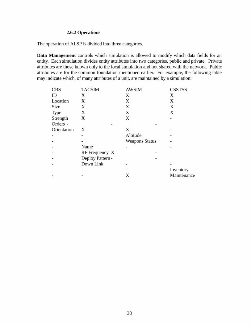
There is one limitation to man-in-the-loop (MIL) simulation which is usually not a factor in
36
parallel computing and parallel simulation. MIL applications are expected to run in real-time,where real-time is defined as simulation time passing at the same rate as clock-time, and using atime step that is appropriate for the level of aggregation of the simulation. If the computers arecapable of performing computations much faster than this, all of their power can not be used.
Extra power beyond that needed to maintain real-time operations can be harnessed to somedegree. If some form of optimistic time warp is being used, the CPU can calculate events in thefuture. This information must then be queued up for later release to the MIL, since it depicts hisfuture, which he is not allowed to know. But, should events from another LP cause a rollback,this pre-calculation must be "un-done" by returning to the state before the new event'stime-stamp. This may endanger the ability of the processor to maintain real-timesynchronization for one or more time-stamps. Since the pre-calculated events were not releasedto the MIL, he will never know that these were preformed, unless the process subsequently fallsbehind real-time.
In the vertical integration environment the major components are DIS and ALSP. Simulationson DIS are expected to maintain accurate event data with update time intervals of 100 or 300milliseconds. ALSP simulations, on the other hand, maintain a time step of 1 to 6 minutes. Obviously, ALSP provides a time buffer, which may allow rollback and recalculation to beperformed without impacting the rate of time flow, DIS may be at risk. This may indicateapplications for optimistic time warp in messages flowing to ALSP, but not for those flowing toDIS.
When constant real-time is required, the power of the computer selected will be impacted by thetype of task it will perform and the type of software algorithms to be used.
Given that we are using a conservative approach, we must acquire a computer that can handlethe maximum load during any given time step. With optimistic approaches, we may be free toacquire a machine which provides real-time operations for some average load over somenumber of time steps which can be integrated.
Again, once the computers are selected, we have limited the size of the scenario and the level offidelity which can be represented. Exceeding this size limit will require more LP's distributedover more CPU's.
On method of parallel simulation is patterned after the Single Instruction Multiple Device(SIMD) computer. Here, one event stream is managed by a single processor. This then servesthe events that they are allowed to process to all of the other client processors. Here, it isimpossible to use optimistic time warp techniques, since each CPU is knowledgeable only ofthe events that the event manager considers "safe" to work on. In many ways, this is identical tomultiple simulation processes operating on the same CPU. The only difference is thataccess/modification to the database is being managed remotely.
In any case, parallel computers are faced with situations in which no two LP's are glued to auniversal time or rate of time progression. Each may be free to live as fast as it can. But whenthese LP's interact, they experience some of the same confusions that Kurt Vonnegut's Billy
37
Pilgrim did in Slaughter House Five. He was continuously coming "unstuck in time", losing allsense of causality and responsibility to the events occurring around him. In T.H. White's, TheOnce and Future King, Merlyn the Magician lives his life backward in time. Beginning life asan old man, and dying as a newborn baby at some later date. As his life progresses, he iscontinually forgetting people and events that happened in the conventional past, which is hisfuture. When simulations experience this, there can be no guarantee of causality and we ceaseto replicate reality as we know it.
2.6 Aggregate Level Simulation Protocol
2.6.1 Origins
In the late 1980's, DARPA conducted some very successful experiments in linking armorsimulators within a single virtual environment, a project known as Simulator Networking(SIMNET) project. As a result, they approached MITRE with a request for a standardinterfacing capability between constructive simulations. The models which they expected tointegrate were primarily training tools used to stimulate soldiers in their various positions incombat. Training exercises, such as Reforger and Ulchi Focus Lens, were typically carried outby one or two large simulations, such as CBS and AWSIM. This project intended to join anymodel with the correct interface into the exercise. The project is now known as AggregateLevel Simulation Protocol (ALSP) [Weatherly, 1991].
ALSP is based on four fundamental design principles gleaned from the SIMNET work:
1) Distributed Computation Based on Entity Ownership,2) Avoidance of Single Critical Resources,3) Reliance on Broadcast Communications, and4) Replication of a Limited Set of Attributes Among all Simulations.
These principles are intended to overcome many of the limitations seen in earlier efforts to joinsimulations. The first, implies that joining the ALSP confederation will not significantlyincrease the computational burden of the simulation. The second, eliminates reliance onresources which can become bottlenecks to the entire system. The third, is intended to allowflexibility such that a simulation may join or leave the confederation during an ongoingexercise. The fourth, is intended to create a common foundation among all simulations for alimited set of entity attributes.
38
2.6.2 Operations
The operation of ALSP is divided into three categories.
Data Management controls which simulation is allowed to modify which data fields for anentity. Each simulation divides entity attributes into two categories, public and private. Privateattributes are those known only to the local simulation and not shared with the network. Publicattributes are for the common foundation mentioned earlier. For example, the following tablemay indicate which, of many attributes of a unit, are maintained by a simulation:
CBS TACSIM AWSIM CSSTSSID X X XLocation X X XSize X X XType X X XStrength X X -Orders - - -Orientation X X -- - Altitude -- - Weapons Status -- Name - -- RF Frequency X -- Deploy Pattern - -- Down Link - -- - - Inventory- - X Maintenance
39
Here "X" indicates that the characteristic is known in some form to the simulation, and "-"
indicates that the simulation does not deal with data of this type (Figure 2-11).
It is the public attributes that require management. Although all simulations may be aware ofthe existence of the entity and the state of its public attributes, this does not imply that they maymodify these attributes. Typically each entity is controlled by one simulation which is thenresponsible for maintaining its attribute states. Events effecting this entity are then routed to itsparent simulation for actualization.
Let us remember the CSSTSS convoy generated by a request from CBS, in the section onDedicated Horizontal Interfaces. There a special message had to be generated to requestCSSTSS convoy resupply. If characteristics of this operation effected any other model, aseparate message would have been sent to those. But, with the advent of ALSP, all simulationsare now on the same network and speak the same protocols. A single standard message cannow be generated to activate all necessary events among all confederation members [CBS-CSSTSS, 1993].
Time Management controls the temporal causality of events among all simulations. Thisfunction is performed for all messages transmitted across the network. In earlier sections, wedescribed conservative and optimistic methods for handling time in a parallel environment. ALSP chose to use the conservative method. The use of optimistic methods would have re-quired that all simulations joining the network operate state-saving and rollback algorithms. Most of these types of simulations do not have such a capability and dictating the creation ofthese algorithms to join the network is infeasible. The simulations also operate with men--in-the-loop. Therefore, each simulation would have to create some type of moving window tostore events and states until they could be released to the humans.
ALSP manages the time of all simulations to create a Global Virtual Time (GVT), which allsimulations are then subject to. To accomplish this, all simulations are assigned a beginningtime, assume day 1 hour 1 minute 0 (Julian 0010100). From there, each is allowed to simulatethe events taking it forward one time step. But, each simulation is free to use a step sizeappropriate to its operations. Therefore, the simulations may step forward out of sequence. But, the minimum of the new current times becomes the new GVT, and is distributed to allsimulations [Weatherly, 1991].
41
ALSP Time tCBS Ops t -> t +
�
tcTACSIM Ops t -> t +
�
ttAWSIM Ops t -> t +
�
ta
Assume that the CBS time step is 6 minutes, AWSIM is 1 minute, and TACSIM is 2 minutes. The new GVT after one step would be 0010101, which would be distributed to all. CBS wouldrealize that is free to calculate from 0010101 to 0010107. But, its 6 minute time step wouldalso dictate that it does not step again until 0010106. Similarly for TACSIM. But, AWSIMwould see that it has arrived at its next desirable time step, and calculate again. Therefore,AWSIM would loop through 6 time steps and TACSIM 3, before CBS would move again. But,when CBS did move again it would include the accumulated events from the other models. Using this method each simulation is free to see the world in chunks that are significant to it. This also allows them to operate in the same manner that they were prior to joining the ALSPconfederation, resulting in a minimal amount of software changes. It is estimated that less than10% of the simulations software will be impacted by joining ALSP.
Architecture is the structure used to join all the simulations to each other and to the network. This consists of protocols, translators, and gateways. Two protocols are used: that between thetranslator and the gateway, and that between gateways.
Each translator is a custom entity which is built to allow existing simulations, such as CBS,TACSIM, and AWSIM, to join the ALSP confederation. The translator changes local datasemantics into global semantics understandable by other simulations. It also performs thereverse translations on incoming messages. This operation will be greatly reduced, oncesimulations are built specifically to join ALSP.
Each gateway transports message packets across the network to all other simulations. Itmanages the addition and removal of simulations during an exercise. Finally, it manages thelocal time, and notifies the network manager of this, so that a GVT can be reached.
In ALSP, simulations are known as actors. They need not be traditional simulations interestedin controlling objects and interfacing with other simulations. They may be data collectors orgraphic workstations which are receive-only systems. The gateways are known as ALSPCommon Modules (ACMs). There is also an actor that is actually part of the ALSParchitecture. The ALSP Broadcast Emulator (ABE) calculates and distributes the GVT for allparticipating simulations.
Since objects are owned by a simulation, this dictates some basic limitations on adding andremoving simulations from the confederation. Prior to the beginning of an exercise, control ofall units must be negotiated and assigned. Once an exercise begins, any simulations joiningmay not assume control of entities which are already owned by another simulation. They must,therefore, bring with them the entities they will be responsible for. This implies that theaddition and removal of simulations must be managed by some exercise controller. Otherwise,entities may appear suddenly in the middle of ongoing interactions, destroying the validity ofthe operation. Similarly, when a simulation is removed from the confederation, all entities that
42
it controls must be removed with it or control passed to another member of the confederation. This may include transferring control to Computer Generated Forces (CGF) models.
The basic steps in entering the simulation environment are:
1) Join the Confederation. This is done by sending a "join" message, which notifies allother simulations and the network of your existence.
2) Refresh Local Data. This is a "refresh" message, which causes all simulations totransmit the public data elements of the entities which they control. This informationbrings the new simulation up-to-date with the situation as it now exists.
3) Operate. The new simulation now operates in the environment as an equal memberof the confederation.
4) Remove. A simulation exits the exercise by sending a "remove" message to thenetwork so that all packet traffic intended for it will be eliminated. This assumes thatthe final part of step 3 was to transfer ownership of any controlled entities that need toremain in the exercise.
The ALSP Operational Specification gives the impression that, although intended to be genericand universal in scope, the project has actually evolved into a proprietary solution to a knownproblem. No explanation is given of the general outline of the message packets to be delivered. The entire document describes library calls for executing a set of known simulationinteractions. This implies that ALSP may be becoming a custom interface such as thosedescribed above, but involving a dozen simulations rather than just two. Although such alibrary of routines is necessary regardless of the generic nature of the interface, it is the lack of ageneral description that leads one to believe that the generic focus has been lost. No attention isgiven to unknown simulations and undefined interface events.
The Defense Modeling and Simulation Office (DMSO) commissioned a panel to reviewexisting aggregate level linkage technologies. This panel made several pertinent observations. First, all current linkage work addresses the perspective of the local simulation organization. None of them is investigating the larger, more general problem of connecting simulations at alllevels. A senior representative of DIS made the statement, "All we are doing is anecdotal; thereis very little theory", emphasizing the need for studies of this type [DMSO, 1993].
The panel concluded that the distinction between vertical and horizontal interfaces is artificial. Simulations can not be neatly divided into virtual and constructive categories. Rather, everysimulation has its own unique representation of reality, and interfacing any two of them presentsunique situations and problems. The recommendation was to develop a common conceptuallanguage for representing combat phenomena, objects, and relationships. Once this is done,simulations can be built which will interoperate naturally, regardless of their level ofaggregation. Although there is a problem of aggregation and disaggregation to be solved, this iscomplicated and confused with the problem of differing conceptual languages between thesimulations. The language must be standardized first.
43
An example of a problem that is both constructive and virtual is found in the air transportationfield. An aircraft in flight is seen by those aboard to be a group of hundreds of individuals andaircraft sub-systems. But from the air traffic control tower it is a single entity with a verylimited set of attributes, few of which are replicated inside the aircraft. By the same token theairport appears as a single entity to the aircraft through most of its flight. But, near landing itsuddenly becomes a set of runways, competing aircraft, and control personnel. Is this aconstructive or a virtual problem? Which direction is vertical and which horizontal?
An essential characteristic of all simulations must be that a problem may be solved with anycombination of simulations that are appropriate. The solution provided by any of them shouldtend toward the same direction. Although, the outcome of specific events may not be the same,the global outcome should be. This is certainly not true with the simulations available today. There are no standards which govern the replication of reality within a simulation. Therefore,the variability that exists prevents any sort of similarity between simulation results. Whetherone chooses a suite of: CBS+AWSIM, CBS+RESA, BBS+AWSIM, CBS+TACSIM,CBS+BICM, etc. , the results should vary because of the Monte Carlo nature of the simulationsand the input provided by the human operators. They should not vary because of the differentmethods of representing reality.
The DMSO study group concluded that in establishing a common foundation of entityattributes, several characteristics should be considered:
1) Minimal software changes to existing models,2) Maximum software reuse,3) Open systems approach,4) Distribute globally,5) Scalable,6) Extensible to, as yet, unknown simulations.
2.7 Distributed Interactive Simulation
Undeniably, the largest simulation interfacing effort, Distributed Interactive Simulation (DIS), isfocused on joining virtual level simulators. These include: armored vehicles, helicopters,aircraft, naval vessels, and individual humans. The project was initially sponsored by DARPA,and has since transitioned to the Defense Modeling and Simulation Office (DMSO) and theArmy Simulation Training and Instrumentation Command (STRICOM). The architecture,protocols, and representation standards are being developed by industry, government, anduniversity representatives who meet at semi-annual workshops to exchange ideas. Theseworkshops started with 55 participants in 1990, and have grown to over 1000 in 1993. Most ofthe work is being funded by simulation project offices, who intend to become members of theDIS network when it is operational, and by industry investment, in hopes of winning contractsin the future [The DIS Vision, 1993].
44
DIS strives to create a cohesive environment in which soldiers can train against an enemy, usingany type of equipment and tactics. The military hopes to present them with realistic combatevents, which can not be reproduced in a physical training environment because of safety,equipment, terrain, and budgetary constraints. It will become an environment in which jointand combined exercises can be conducted. A joint exercise is one in which multiple servicesparticipate - the army, air force, navy, marines, national guard, and coast guard. A combinedexercise includes U.S. allies, particularly members of NATO and South Korea.
There are three primary advantages to performing virtual exercises rather than physical ones. First, they are relatively inexpensive. The military watched the cost of the large, Germanexercise Reforger drop from $115 million to $22 million, as they added more simulations toreplace physical activities. With DIS they hope to train pilots in a simulator, and experience thissame level of savings. Second, the exercise can be distributed. For a physical exercise, all ofthe participants must be brought together on a common playing field. Transporting and housingthe troops and equipment is a major undertaking, requiring long planning periods and largepieces of terrain. Networked simulators can exist anyplace in the world, and yet appear to beoperating together in the same area. This need is increasing as the NATO countries no longerperceive a serious threat from the Soviet block. Their farmlands had been a primary playingfield for these very destructive exercises. Third, simulations are more secure than physicalexercises. When practicing combat tactics across large physical areas our opponents usuallysend observers who collect this information and use it to plan their defenses and counter moves. If events occur inside a family of networked computers they can be masked by limited networkaccess and encryption.
In addition to the training benefits, the Army Science Board sees this type of simulation asuseful in the system acquisition process, the test and evaluation of new equipment, and combatrequirements development.
DIS is founded upon six basic concepts.
1) No central computer for event scheduling or conflict resolution,2) Autonomous simulation nodes responsible for maintaining the state of one or moresimulation entities,3) A standard protocol for communicating "ground truth" data,4) Receiving nodes are responsible for determining what is perceived,5) Simulation nodes communicate only changes in their state, and6) Dead reckoning is used to reduce communications processing.
Supplementing these concepts are the eight key design principles.
1) Object oriented entity design,2) Defined sphere of interaction for entity cause and effect,3) Common beginning gaming area environment,4) Database driven model designs,5) Synchronous and asynchronous interconnections,6) Local models determine level of resolution and aggregation,
45
7) Simulation management for cross-entity functions, and8) Communications services will provide functionality required for interconnectionbased upon the OSI network model.
All of these lead to a DIS architecture as visualized in Figure 2-12.
The DIS network will function like the Internet in many ways. The intent of both is to supportusers world-wide without allowing local node problems to disrupt the operations of the entirenetwork. A DIS network is designed to support multiple independent exercises simultaneously. To do this, each exercise is assigned an "exercise number". To use the network, an exercisesponsor must submit information which will allow the network controllers to determine thebandwidth that will be required, based upon the number and type of nodes, the geographic areato be covered, and the level of aggregation. If sufficient bandwidth is available during theperiod requested, the exercise is approved, if not, negotiations will determine the best alternatetime for both parties.
In order to participate in a DIS exercise a minimal level of interface functionality has beendefined. These are enumerated in Figure 2-13 and 2-14. The functionality is designed to insurethat no node takes advantage of others by rendering some lower level of entity interaction,making it impossible to detect, kill, or communicate with.
Communication between simulation nodes is done with a set of standard Protocol Data Units(PDUs). These are designed to provide a foundational view of the battlefield for allparticipants. Each node is free to inject any detail that is only needed locally, as long as it doesnot distort the public view portrayed by the PDUs. The most commonly used of these is theEntity State PDU. This describes the object of each node to all other nodes. This PDU is
Figure 2-12. DIS Architecture
46
shown in Figure 2-15. Some of the other PDUs are listed in the Figures above, but there areothers which are designed for very specific needs. Since DIS is still in the design phase, PDUsare changed and added at almost every workshop.
As with all communication, latency in data transfer can be a problem. DIS establishes twolevels of interaction with guaranteed minimal latency of 100 and 300 milliseconds, and a lowvariance in these numbers. Entities that are considered "tightly coupled" must maintain a 100millisecond communication rate. These may include fighter aircraft flying in formation. "Loosely coupled" entities are allowed to communicate at a rate of 300 milliseconds. These areentities in the same sphere of interaction but who are not interacting with each other, such as atank and a fighter aircraft. The latency variance has not been qualitatively defined at this point.
Figure 2-13. DIS Functional Requirements
Figure 2-14. DIS PDU Requirements
Figure 2-15. DIS Protocol Data Unit
47
Simulators perceived to be able to operate in this environment in the near future are listed inFigure 2-16. Many of these are still under development, and so are being designed with the DISstandards in mind. These should be able to optimize their DIS performance, where existingsimulators may find the DIS requirements more difficult to implement. The goals of the DISprogram are very aggressive and have been defined at varying levels of detail through the next
several years in the DIS Operational Concept.
Figure 2-16. DIS Programs
48
Based upon standard PDUs and network structure, DIS can be visualized as in Figure 2-17 and18. Like the Internet, DIS is comprised of a network of networks. LANs connect a geograp-hically grouped set of simulators, which then join a WAN along with other LANs in a similarconfiguration. It is probable that many of the "tightly coupled" simulators will be found amongthe members of the same LAN. This will reduce network traffic across the WAN. Therequirements for the LAN and the WAN may differ because of the types of functions needed. Each LAN may be controlled locally and have no need for encryption, for example. The WANmay be a military network or it may be provided by a commercial entity. Here, encryption willbe essential, incurring processing overhead which impacts data transmission rates.
Currently, all communication is performed via broadcast messages. The DIS committeesrealize that, as the number of nodes climbs from 1,000 to 100,000, this technique will not scale. Therefore, there are efforts to create methods to multi-cast packet distribution on the network. This is probably most essential in the WAN environment, and may not be necessary on theLAN's. Experiments have been performed using the SIMNET project to identify the level ofPDU exchange that will be experienced in DIS. These indicate that DIS will be able to functionwith 1,000 entities on an FDDI or ATM network, but the multi-casting problem must be solvedif the number of nodes is to grow to the 100,000 entities envisioned [Smith, 1994].
The results of one of the studies are summarized in Figure 2-19. In this study, three differentcategories of PDU exchange were used: ground movement, air movement, and radiocommunications. The last indicates an area where multi-casting will be extremely useful. Inthe experiment, 60 communication channels were simultaneously operated. With broadcastcommunications, all of this information must be transmitted to each simulation node. Thenodes then determine which of the data is useful. If the nodes were assigned to multi-castgroups according to the radio channels they were currently using, this would decrease theinformation received by orders of magnitude. Of the 60 radio channels in operation, a given
node may be using one or two of them, eliminating 58 or 59 of the data steams propagated tothat node.
Figure 2-19. DIS Network Performance Analysis
50
Another issue being addressed, is the geographic coordinates to be used in DIS. It does notmatter what coordinate system nodes use locally, but each must be able to translate this into astandard form in order to communicate with others. The DIS standard is a three-dimensionalgeocentric system, represented as Latitude, Longitude, and Distance from the center of theearth. Many existing simulations were designed to operate in a very limited area and weretherefore free to generate their own local coordinate systems. These may have been a standardCartesian x-y-z or the Army UTM. Unfortunately, neither is appropriate for interaction andcommunication with simulators operating in geographically dispersed areas. Therefore, thesemust be converted to the new system, or the node must use a translation algorithm incommunicating with other nodes. The latter is more common for existing simulations. Theproblem is illustrated quite well in Figure 2-20a-c. The DIS coordinate system and theSIMNET coordinate system are shown for entity location (20a) and for entity orientation(20b-c) [Lin, 1993].
Figure 2-20. Virtual Body Coordinate System
51
In accordance with DIS's ambition, they intend to add interfaces with real-world entities such astroops in the field, operational aircraft, and ships at sea. The first step in accomplishing this isto assign an accurate location to each of these. This will be done by equipping each with aGlobal Positioning System (GPS) receiver and a transmitter. The GPS will calculate positionbased on orientation from the GPS satellites in orbit, an elaborate triangulation problem. Thiswill then be transmitted to a "Central Node" which will be responsible for injecting theinformation into the DIS simulation network (Figure 2-21a-b). Communications will betwo-way, enabling the simulation to tell real-world participants the level of damage incurred
Figure 2-21. DIS Connections to Live Equipment
52
from simulated entities and which network entities are detectable by real unit sensors. Transmitting damage/kill information will result in the same actions that occur now in thedigital environment. If a soldier is involved in a field exercise using laser enhanced weaponsand sensors, a "killed" signal will deactivate his rifle and signal the kill. Making simulatedentities appear to real sensor systems will be more difficult. Virtual reality technologies areenvisioned to cue human eyes and ears. Radar, infrared, and sonar systems must be integratedwith a simulation module, which will inject the simulation information just as if it had beenrelayed from the sensor's antenna. This type of real-world interaction will remain in theexperimental and demonstration phases for many years to come.
2.8 Computer Generated Forces Models
The DIS community has recognized that it is impossible to acquire simulators for all of theobjects found in a typical combat engagement. But, without these entities, the environmentdoes not sufficiently replicate events that will occur in an actual war, reducing the value ofsimulated training. In fact, the ability to generate more simulated entities than one can fieldphysically is one of the attractive advantages of simulation-based training exercises.
Since the DIS community envisions simulations with 10,000 to 100,000 entities, most of thesemust be generated and controlled by computer models. These models will be either completelyindependent of human interaction, or controlled at some macro-level. These have come to beknown as Computer Generated Forces (CGF). As they exist today, they have much in commonwith constructive simulations. Where a DIS simulation replicates a single object (tank, truck,helicopter, aircraft, etc.), a constructive model replicates thousands. CGF is an attempt to use asingle model for multiple objects, without losing the fidelity provided in the virtual world. Thisattempt to take the best of both worlds makes these model a natural bridging mechanism forvertical integration.
The DMSO commissioned a survey of the different CGF models and techniques being used[DMSO, 1993]. In doing this, they set four criteria that a model must meet:
1) DIS compliant. It communicates with the outside world via DIS PDUs. 2) Real-time interface.3) Entity-level representation of combat elements.4) Credible surrogate for the behavior of manned units.
With these criteria they found eight models which could be considered CGF and another fivewhich were moving in that direction.
Comprehensive CGF CGF RelatedBBN SAF 4.3.3 IBM Blackboard ResearchModSAF UCCATS/JCM/AMOEBABDS-D CGF BBS/DISIFOR/WISSARD Eagle-SAF-SIMNET
53
CCTT SAFOR RESA-UVASWEG/SUPPRESSORIST SAFORJanus A
The executive overview of the study states that several good ideas are found in the CGFarchitectures and should be used in future development. These are:
- Explicit representation and capture of command and control information,- Standardized messages and formats for command and control across all echelons,- Modular, reconfigurable entity representations,- Distributed storage of state information,- Arbitration schemes for resolving conflicting goals,- 3-D view controllable from CGF operator console.
They also found notable weaknesses:
- No development structure. Do not use existing algorithms,- No documented, robust set of requirements,- No structure for including other projects in the development effort,- No interface with the DIS PDU and terrain development groups.
The broadness of DMSO's criteria included models which are not all useful in our discussion ofvertical simulation integration. Therefore, we will discuss only those models that offer promisein this area.
2.8.1 ModSAF
Of the CGF models BBN SAF 4.3.3 and ModSAF can be discussed as a single entity. Althougheach may be found in use on different projects, ModSAF is the current, growing model. The
Figure 2-22. ModSAF Development Timeline
54
BBN SAF is an earlier baseline used in the SIMNET project (Figure 2-22) [ModSAF, 1994].
When one hears the term computer generated forces, one may naturally assume that some typesof artificial intelligence techniques will be involved. This is not the case, although knowledge-based and rule-based systems are present. ModSAF does not use either of these. In fact, it is anattempt to create a user interface in which a single operator can control 50 to 150 entities. Allof these entities and the environment in which they operate, are modeled at the DIS virtuallevel, so it can not be considered a constructive model, even though there are similarities. Thisdetail limits a ModSAF suite to tracking 1,000 total entities.
The ModSAF operator uses a 2-D graphic plan-view display (God's eye view) showing a terrainmap and object icons. He is then responsible for manipulating these such that they present acredible force to the virtual level simulators they are interfaced with. Although the display maylook constructive, the models do not contain many of the statistical characteristics ofconstructive models. For example, where CBS may determine object-to-object visibility usingaverage terrain and Monte Carlo decision algorithms, ModSAF deals with actual terrain pointsand calculates the actual intervisibility for each encounter. This type of difference was one ofthe primary causes for the development of CGF models, rather than the adaptation of existingconstructive models.
ModSAF contains four distinct databases, two local and two virtual. The local are the terraindatabase and the object parameters database. These provide the beginning picture of thebattlefield. The terrain does not change through a war, though dynamic terrain is an activeresearch area. The Object Parameters describe the entities that are owned and controlled by theModSAF model. These characteristics change as combat events unfold. The virtual databasesare those which are created and updated by external models sharing the network with ModSAF. These are the Persistent Object database (PO-DB) and the DIS database (DIS-DB). ThePO-DB creates the battle scene which includes external entities. It is dynamic and includes thecontents of the Object Parameters database. The DIS-DB contains all of the messages that havearrived from the outside world. These include those that have created the PO-DB and othersinvolved with simulation management.
55
ModSAF is composed of three distinct models: SAFstation, SAFsim, and SAF-logger (Figure2-23). SAFstation is the user interface provided to the operator. This is a 2-D map withdrawing tools, terrain analysis tools, and mission planning templates. With a single SAFstation,an operator may control a single or multiple SAFsim processes, which actually model objectactivity. An operator is responsible for constructing missions for the entities he controls. Missions may involve multiple objects and they span a period of time, referred to as a missionmatrix. Multiple matrices within the same SAFstation are referred to as a matrix stack. Onceconstructed, the matrices and stacks are given to the SAFsim for execution. The operator mayalso interactively enter commands based on the combat situations displayed on the screen.
SAFsim manipulates the entities it controls based on the mission matrix stacks, interactiveorders, local terrain information, and enemy unit engagements. A separate task manager foreach simulated object takes events from the queue and executes them. Objects use avoidancealgorithms to modify their behavior to maneuver around trees and rivers. SAFsim contains fourdifferent model libraries which define the level of fidelity of the simulation. These are:
Hull models which control the movement of the object,Turret models which control the aiming rotation of weapons and sensors.Weapon models which perform probability of hit calculations.Sensor models which determine whether detection has occurred.Damage models which determine the level and type of damage given a hit.
Figure 2-23. ModSAF Components
56
Each of these is directed by tasks such as movement, terrain, search, and targeting (Figure 2-24). When appropriate, objects seek to engage enemy units that are encountered.
SAF-logger records all incoming information and the conditions under which decisions weremade. These are used to evaluate the models and the to replay the results of combat events.
ModSAF is a purely interactive simulation with automatic terrain avoidance and engagementalgorithms. Since the locations of all entities are stored in the DIS-DB it is possible to passcontrol of certain objects from one SAFsim to another under the same SAFstation. This createsa method of load balancing and fault tolerance which makes the system attractive. ModSAF isdesigned to operate on a 2Hz update cycle when fully loaded. This does not comply with theDIS 100 - 300 millisecond standard for manned entities. The impact of this is not currentlyknown.
A quick glance makes it clear why some type of bridging model is needed between DIS andALSP, and why ModSAF is considered for this function. In a vertically integrated exercise,
Figure 2-24. ModSAF Model Libraries
57
given that DIS may field 1000 simulators (very optimistic), 19,000 must be controlled byModSAF. Assuming that those 1,000 DIS are geographically grouped, and therefore encounterat most half of the CBS objects, this is 9,500. As currently designed, this will require 64ModSAF simulation suites, which is a feasible number for initial vertical interface experiments.
58
2.8.2 IST SAFOR
The IST SAFOR was commissioned as a low cost system. It resides on an 80386 based PC,using the MS-DOS operating system. Promising work has been done to perform terrainreasoning and weapon selection for the controlled entities. But, it is designed to control only asingle object. As a system, it can not be used for vertical integration, although the algorithmsand model architecture may be employed in future CGF systems.
2.8.3 IBM Blackboard
The IBM Blackboard Research is based on artificial intelligence (AI) techniques. A single,common blackboard is used to record and modify information from several different sources. Units and events are monitored by AI algorithms, which use these to make decisions. Decisionsare then translated into actions for locally controlled objects, and commands are issued to carrythese out. Experiments have been done with two platoons of M3 Bradley vehicles and SovietBMP's, but the results are not published in the DMSO report. Although just a research project,it aims for the capabilities needed for a vertical interface.
2.8.4 Rasputin
Although not included in the DMSO survey, the Rapid Scenarios Preparation Unit forIntelligence (Rasputin) has the ability to perform CGF functions. This system was built toprovide a simple graphic interface in constructing a scenario, including timed movementpatterns. Commands are issued at levels of organizational aggregation, such as battalionheadquarters. The stated objective is simply to move from point A to point B. Lower levelobjects are then constrained to follow realistic courses through the terrain database by a rule-base of military operations. This requires that they follow roads, avoid obstacles, and optimizetheir paths. A knowledge-base containing thousands of rules is used. Unfortunately, the systemcan not provide real-time calculations of these steps. It is meant for engineering-level studies. The exact time required to calculate movement is not generally known to the simulationcommunity. The DMSO study identified four enabling technologies necessary to create true ComputerGenerated Forces.
1) Behavioral representation of decision making. 2) Processing and interpreting terrain information. 3) Exercise support (scenario generation, plan development, and live analysis).4) General computing technologies, to include processing speed, parallel processing,networking, and computer image generators.
As these technologies develop, the ability to truly generate and control realistic units viacomputer will grow.
2.9 Vertical Integration Prototypes
59
There are currently several experimental projects being conducted on the viability of connectingvirtual and constructive level simulations. All attempt to join one virtual and one constructivesimulation, with a CGF model as the bridge. The first step is to disaggregate a constructiveunit, such as an armor company, and instantiate the objects of that unit in a virtual simulation. The second step is to assign virtual attributes to those disaggregated objects. The third step,which is currently missing, is to automate the operation of those objects in the virtual world.
2.9.1 AWSIM to ModSAF
The Air Warfare Simulation (AWSIM) is one of the members of the ALSP confederation. It isresponsible for controlling fixed wing aircraft and surface-to-air missile batteries [SummaryReport: The Ninth ..., 1993].
The Modular Semi-Automated Forces Model (ModSAF) is the leading CGF model in the DIScommunity. The first capabilities developed in the model were air-to-air and air-to-groundoperations.
These two models are being joined by the MITRE corporation as part of the ARPA SimulatedTheater of War (STOW) 94 demonstration. The requirement is to use AWSIM to generate andcontrol aircraft sorties in support of a virtual level exercise. To accomplish this the combat areahas been divided into two sections. The AWSIM/ALSP box is the large area and completely
contains the smallerDIS/ModSAF area (Figure 2-25).
AWSIM controllers will generate missions in response to support requests from the exercise
Figure 2-25. AWSIM to ModSAF Functionality
60
participants. These missions will be launched from AWSIM air bases, complete with theappropriate number of aircraft, fuel, munitions, sensors, a flight path, and an objective. Oncelaunched, the AWSIM flight model controls the mission until it enters the ModSAF play box. At that point, control is handed to ModSAF and the mission becomes a ghost unit in AWSIM. As a ghost, the mission will not be attacked by AWSIM air defenses or enemy aircraft. Thisresponsibility now rests upon the networked DIS simulators. AWSIM now tracks only thegeneral location of the mission, in preparation for receiving control back from ModSAF forafter action analysis. Once the aircraft exit the ModSAF box, control returns to AWSIM inorder to complete the mission. While in AWSIM, aircraft must operate in the electronicwarfare, air defense and air-to-air combat environment native to the model. This allowsAWSIM to widen the scope of the scenario being replicated in the DIS-level STOW exercise.
While in the ModSAF box each aircraft is individually instantiated and controlled by theModSAF operator. This task is man-power intensive and will require several ModSAFoperators for each AWSIM operator generating the missions. Since AWSIM is operating in asupport function, independent decision making may be exercised in mission composition,arming, and flight path generation, based upon objectives supplied by the DIS commanders.
To enable this technique, ModSAF was joined to ALSP as a quasi-member of theconfederation. Special messages and algorithms had to be created to enable this, sinceModSAF does not posses all of the characteristics of a constructive model, nor are ALSP and itsmembers the driving force of the demonstration exercise. This structure will test the usefulnessof constructive simulations in enhancing virtual exercises. But, the ultimate goal of verticalintegration is to allow both levels to participate equally in a simulated environment.
2.9.2 JPL Alpha Project
61
The NASA Jet Propulsion Laboratory has created a research effort dubbed the Alpha Project. This is an attempt to bridge the constructive-virtual gap, using mathematic algorithms, ratherthan man-in-the-loop simulators such as ModSAF. Although in its infancy, the project hasbegun to define splines for continuous flight-paths from the discrete mission points given in a
Figure 2-26. JPL Project Alpha Links
62
constructive simulation. They are also defining sampling criteria for replicating a mission flightprofile from a continuous DIS flight-path (Figure 2-26a). A DIS flight-path is actually adiscrete set of points, just as in the constructive world, but these points are defined to be100-300 milliseconds apart. Should an object not deviate from its last orientation, deadreckoning (DR) algorithms are used to project its position along the last known vector. Therefore, the sample is made to meet these criteria and minimize network data traffic (Figure2-26b).
The project has defined the constructive piece as the Advanced Simulation Framework (ASF)in the Figures. This framework may represent enhancements to existing simulations. such asAWSIM and CBS, or an architecture to be used in constructing the next generation ofconstructive models. Though the later is the most desirable, budgetary constraints and projectdemands will influence the development and implementation of this research project.
2.9.3 Eagle to BDS-D/SIMNET
Eagle is an Army TRADOC Analysis Command (TRAC) model for constructive corps anddivision level combat operating on a Symbolics and a Sun workstation. Units are representeddown to the company and battalion level. It is used to conduct combat analysis studies forevaluating weapons systems, command and control, military doctrine, and the effectiveness oforganized forces [Hardy, January 1992].
Battlefield Distributed Simulation - Developmental (BDS-D) is a program designed to bringmultiple virtual simulations together in a shared environment. The Simulator Networking(SIMNET) project is a group of armored vehicle simulators that have been networked into ashared virtual environment. The actual interface with the constructive world is via the Institutefor Simulation and Training's Semi-Automated Forces model (IST SAFOR). This is a PCbased model comprised of an Operator Interface (OI) computer and a simulator computer. Asdescribed in the CGF section, IST SAFOR primarily performs terrain reasoning and someweapon selection decisions preparatory to combat. All other operations are handled by humanoperators.
63
There are several similarities between this project and the AWSIM to ModSAF project,although this is more ambitious. It attempts to maintain a simulated environment in which boththe virtual SAFOR and the constructive Eagle participate equally (Figure 2-27). Eagle is notjust a support tool for a SIMNET exercise. In joining Eagle and IST SAFOR, every effort was
made to maintain the independent operating capability that each started with.
Figure 2-27. Eagle to BDS-D Functionality
64
The Eagle play box is a 100km by 100km square. Within this box, are one or more smallerCGF areas where IST SAFOR operates. Each CGF area is controlled by one or more ISTSAFOR models. The number required is completely dependent upon the number of vehiclesoperating within the area. Unlike AWSIM/ModSAF, an Eagle unit does not disaggregate uponentering the CGF area. Disaggregation points have been defined within the CGF area. Theseform gateways for transferring control from Eagle to IST SAFOR and back (Figure 2-28). TheEagle and SIMNET worlds are parallel layers like a multi-dimensional chess board. The disag-gregation points are the only portals for traveling between these layers. Multiple CGF areas canoverlap and the IST SAFOR model receiving the Eagle unit is determined by the portal that isentered.
When an Eagle aggregated unit enters one of the portals to CGF, unit control is passed to theIST SAFOR model. Within Eagle, the unit no longer moves, although it can still receiveoperator orders. Once transferred to IST SAFOR, an Eagle unit is disaggregated and the objectsbegin to appear in the SIMNET world connected to the CGF models. This magical apparitionis a characteristic that must be eliminated at some future point in the project. The vehicles arenow controlled by the IST SAFOR operator, with the aid of the terrain reasoning algorithms. The manual work-load, together with computer processing limits determines the number ofobjects that can be controlled in each CGF model.
Figure 2-28. Eagle to IST SAFOR Gateways
65
Unlike AWSIM/ModSAF, when an Eagle unit has turned control over to the CGF, it is stillvulnerable to other aggregated units operating in Eagle who have not entered the portal. Theunit's position continues to change as the CGF objects move. The location is the center of massof the CGF objects. Enemy objects detected by Eagle objects within the CGF are alsoregistered as detected in the constructive model and appear on the constructive operator'sscreen.
When the Eagle operator wishes to regain control of the unit, he simply issues a movementorder which will take it out of the disaggregation portal. The objects then disappear from theSIMNET world and the aggregate unit continues standard constructive operations within Eagle. A unit will also be reaggregated out of the CGF back into Eagle if the center of mass of thedisaggregated objects moves outside of the transfer portal.
In addition to the above capabilities the developers have created the ability to receive indirectfire within the SIMNET world from an Eagle artillery unit (whether constructive ordisaggregated into the CGF). The CGF operator sends a request for fire to the Eagle operator,who manually enters the order directing the salvos into the CGF area. The shells enter in theSIMNET world creating visual explosions and actual damage. The damage may effectSIMNET objects and disaggregated Eagle objects.
The developers of the Eagle/BDS-D interface report that it is possible to operate at two levels offidelity. In the first, disaggregated units in the SIMNET world appear as individual vehicles. Inthe second, Eagle units appear as a single constructive icon in the SIMNET world. Thisprovides a level of integration which does not require large amounts of network traffic.
In the above discussion, one point that needs to be clarified is that Eagle units disaggregate intothe CGF, where they may engage other CGF units, whether organic to the CGF or disaggregatedfrom Eagle. The disaggregated units may appear visually in a networked SIMNETenvironment. But they do not exist there in any other way. They may not engage with otherSIMNET objects to damage them or be damaged by them. The appearance capability isprovided only in order to create a realistic "looking" scenario in SIMNET and to stimulateSIMNET sensors.
2.9.4 BBS to SIMNET
The Brigade/Battalion Battle Simulation (BBS) is used to train brigade and battalioncommanders in combat decision making. The commanders operate in a field command postfrom which they issue orders based on the battlefield they see on their maps. These orders arereceived by soldiers operating BBS computer terminals rather than by their real-worldequivalents in the field. The combat events are then executed in the BBS model and the resultsrelayed back to the command post. BBS is very similar to CBS, but with a slightly higher levelof resolution. BBS operates on a 15 second time-step, CBS on a 1 minute time-step. BBS is anetworked simulation. Multiple company-level nodes are connected together to simulate abrigade or battalion. Each object is instantiated at a unique location. These characteristicsmake it similar to the network of object simulators in the virtual world [Summary Report: TheNinth ..., 1993].
66
SIMNET and the SIMNET SAF have been defined earlier in the paper.
This integration project has proceeded much as the Eagle to BDS-D interface. The primarymethod of joining the constructive and virtual worlds is to insert a CGF model between the twoand build interfaces to it on both sides. The CGF model used for this project is known as theSIMNET SAF. This is the original Semi-Automated Forces model developed to supportSIMNET exercises between networked tanks and helicopters. Therefore, the interface betweenSIMNET and SIMNET/SAF already exists. Figure 2-29 shows the integration architecture of anetwork of BBS nodes and a network of SIMNET nodes. Since both the upper and lowerpieces of the picture existed, all work has been focused in the intermediate level named theAIUBBS. The SAF Engine shown in the Figure is the SIMNET/SAF. SIMCON and the
Figure 2-29. BBS to SIMNET Connections
67
AIUSAF were built for this project.
During phase one of the project the goal was to create the appearance of BBS controlled units,disaggregated by the SAF, in the SIMNET world. These unit/objects were then to moveaccording to orders given by the SAF operator and the characteristics assigned by the BBSoperator. This has been accomplished.
The goals of phase two were to create a functional prototype in which units and objects couldinteract in active combat. This too has been accomplished. What remains is to expand thedegree or interaction and the sharing of events. The "BBS/SIMNET Functional Validation TestReport" describes the results of the phase two test. Although conceptually a test, the integrationis limited by several design characteristics of the BBS, SAF, and SIMNET models.
The decision to disaggregate a BBS unit into the SAF and SIMNET world is based on itsproximity to a SIMNET object, rather than by entry into geographic transfer areas. When aBBS unit is within 5km of a SIMNET object, a message is sent to the AIU informing it that adisaggregation must be performed. This results in the AIU preparing the data required by theSAF to instantiate all of the objects of the BBS unit in the SAF/SIMNET world.
The SAF engine receives this data and creates the appropriate objects. These are then visibleand active both in the SAF and in SIMNET.
The AIU manages the differences in time progression in the virtual and constructive world. BBS time progresses in 15 second intervals. SIMNET time is continuous. Therefore, unitmovement within each BBS time-step is buffered in the AIU and the final unit state is releasedto BBS at the beginning of its next time-step. If SIMNET movement does not deviate from thelast reported heading and speed, there will be no new messages for the units position. Underthese conditions, the AIU calculates the dead reckoned (DR) position of the objects at the endof the current BBS time-step. Since the ultimate goal is to join constructive simulations with aDIS standard network, rather than a SIMNET standard, the AIU was designed to be able totranslate BBS messages into either DIS or SIMNET packets. This will allow migration to theDIS network at some future point.
The SAF engine creates and deletes objects according to their relative locations between theBBS and SIMNET entities. SAF is responsible for moving units according to the last suppliedorientation and speed. It must also position the objects of a disaggregated unit according to theBBS supplied "firing posture". This posture indicates a template for the formation of theobjects belonging to the unit.
The Simulation Controller (SIMCON) is responsible for providing some of the automatedfunctions available in BBS, but not in SAF or SIMNET. These include the effects of airsupport, combat engineering, resupply, and automatic responses to combat losses (defensivepositioning and withdraw). These functions provide a realistic looking scenario in the virtualworld, but are functionally inert. For example, minefields can appear in the virtual world, butthey will have no effect on objects driving over them.
68
In this project, the SAF has been designed to model operational units, rather than simpleunrelated objects. Since the relationship between objects is maintained, this allows response bythe entire unit to external events. One instance of this particularly impressed observers at thevalidation test. A flight of two helicopters passed in front of an air defense battery. One of thehelicopters was shot down. In response to this, the other helicopter dropped in altitude andturned to engage the ADA battery. Had each object been maintained without the relationship of"2 ship flight", the surviving helicopter would have continued on its original course and wouldhave been destroyed as well.
BBS/SIMNET has also implemented the ability for constructive artillery to fire into the virtualworld and cause damage.
It appears that this project has made an excellent choice of two simulators to be interfaced. Thenetworked nature of BBS, and its 15 second time-step, make it more compatible with the DISworld than either Eagle or AWSIM. A map of the computer architecture is shown in Figure 2-30.
The approach used by the AWSIM/ModSAF project is particularly forward thinking. Theyrealize that the constructive world will be joined by the ALSP and have tried to use thisstructure in their vertical integration. The BBS/SIMNET interface has begun with, what seemsto be, a natural marriage or constructive and virtual models. This may avoid discontinuity longenough to provide a bridge, without some of the compromises that would otherwise arise in thedesign.
We would like to point out that all of these vertical prototypes are man-power intensive. Duringan actual exercise, this man-power must be taken from the units being trained. This is one ofthe problems with constructive simulations today, they require that only part of a unit receivesrealistic training, while others members are supporting the computerized infrastructure. Addingthe load of maintaining a vertical bridge may exceed the ability of military units to operate withthe staff remaining to them.
69
Figure 2-30. BBS to SIMNET Functionality
70
Chapter 3
Translational Functions
In order to construct a vertical gateway between simulations, we must first identify the type ofdata that must be passed across it, the environment in which it will be used, and the translationsthat this implies. In considering these we will use an example in which a known aggregatedunit in a constructive simulation is communicating with the known objects that make up such aunit in the virtual world. We will consider first the cases of translating from constructive tovirtual, and then from the virtual to the constructive.
One of the first issues to arise is whether considering a single constructive simulation and asingle type of virtual simulator is sufficient. The answer to this will unfold as we explore theissue of unit control versus representation. Since the DIS and ALSP projects are attempting toforce a standard on simulation integration, the problem should not be impacted by the type ofsimulation we choose to integrate with.
In creating the vertical bridge, we are making assumptions based on military doctrine,experience, and our understanding of the uses to which the simulations are being put. Thisresults in a loss of human generated unpredictability.
3.1 Relationships
The first step is to determine the relationship between the constructive entity and the virtualobjects. It is common to aggregate into military units such as companies, battalions, andbrigades. The military has the very useful characteristic of defining the composition,operational characteristics, command structure, and options available to these units. In theoryeverything a soldier does in the field can be traced to a manual which was written to trainmillions just like him to behave in a predictable manner. This characteristic is absolutelynecessary in order to create a fighting force that can be directed with the least amount ofconfusion and variation.
71
3.1.1 Templates
Doctrinal behavior allows us to build templates which are software instantiations of the rulesdescribed in the military manuals. These should then mirror the desired behavior of the militaryunit.
A trivial case is that in which a single object, say a tank, is aggregated into a constructivemodel. This is shown in figure 3-1a. In both levels of simulation the icon displayed representsthe same piece of equipment. But, once it begins to operate, it with be acted upon by differentmodels of the environment. A more complex, and more common, case is shown in figure 3-1b. Here, a tank company is composed of various pieces and numbers of equipment. These may
include tanks, trucks, jeeps, humans, and small arms. The problem of maintaining consistencyis much increased.
To define the placement of the objects in the complex unit we must determine its type, size, andactivity. These three characteristics will provide a basic template for operational deployment. Our unit is an ARMORED, COMPANY, in CONVOY. This implies the shape of the unit asbeing in a road march, the equipment arrayed in columns proceeding down a road. It alsoplaces the command tank at a certain location in these columns. This basic deployment willthen be acted upon by characteristics of the environment - the width of the road, the proximityto the enemy, the time of day, the mission objective, and the surrounding terrain. Again, we canrely on doctrine to give us the perfect pattern in which to array our pieces of equipment. Ifseveral tank companies were to be disaggregated from a larger battalion, the method ofdeducing the deployment would be essentially the same. In discussing the deployment pattern, we are actually defining the physical location and
Figure 3-1. Constructive-Virtual Unit Relationships
72
orientation of the objects. These are some of the primary characteristics needed in describing anobject. Assuming that the aggregate unit also knows the types of objects it contains, a mappingcan be made which identifies the virtual objects that match these. This provides the appearancecharacteristics often needed in the virtual world.
3.1.2 Dynamics
We have hinted at the fact that the unit will not exist in a vacuum, but in an environment whichwill have some impact on the template so neatly laid out in the military manual. Several ofthese modifiers have been listed, but their exact effects have not been defined. It is not ourintent to enumerate them here. We merely wish to point out that the modifications have alsobeen distilled from centuries of lethal combat situations and placed in manuals in an attempt tomake current forces more survivable and effective than their predecessors. In addition to theprinted word, we may modify the deployment patterns by information gathered from militaryexperts and Monte Carlo methods. The latter are used to introduce that amount of randomvariation found in all human activities. This imparts an unpredictability that makes the unitsappear to be even more human. Rules are needed to bound the randomness and prevent thedeployment from becoming chaotic.
Given that the aggregate unit is disaggregated into the virtual world, does the fact thatenvironmental factors entered into the locations of the vehicles have any impact on the locationor orientation of the constructive unit? This depends upon which simulation is actually incontrol of the objects/units we are considering, rather than just representing them. This will beexplored further in a later section.
Viewing the above situation from the virtual side, we see a different problem. Given thelocations of a set of objects known to belong to a specific constructive unit, what is the derivedlocation of that unit? The first to answer this question will respond that we should average thelocations of the virtual objects to arrive at the constructive location, and perhaps some type ofweighted average can be used.
Unfortunately, this answer is too simple to suffice. Remember that the constructive to virtualtransformation was accomplished via a template based on a defined command point. Averagingvirtual locations will certainly not arrive at the same location of the aggregate unit that mayhave been used to lay-down the virtual objects, originally. A more accurate method is toappoint one of the virtual objects as the command element. Its location will then be used as thelocation of the constructive unit. This scheme will produce a more realistic and consistentrepresentation of the forces. The constructive location is typically determined by the location ofthe command element as reported to upper levels of command. This object/location may noteven coincide with the actual location of a physical piece of equipment. The command objectmay be the instantiation of a unit characteristic in object-form to produce the desired effect.
Even using this method, the location of the constructive unit that is derived from the virtualobjects may not be the same as that of the original constructive unit from which the virtualobjects were disaggregated. Remember that the virtual locations are all effected by the virtualenvironment. Since the details of this are available only in the virtual realm, it is impossible for
73
the constructive model to take these into account in placing the constructive unit. Given thatthe mission is to join disparate simulations, this is an artifact that can not be avoided.
3.1.3 Consistent History
Given that a complex unit has disaggregated into the virtual world, the virtual objects will beginto experience unique individual changes. Virtual models will move these objects into newformations not totally consistent with the locations that would be derived from templates,doctrine, and environment factors. Certain vehicles will be destroyed or damaged. Differentequipment types will consume supplies, such as fuel, at different rates. These types of changescreate the dynamic, variable battlefield that is valuable for the trainee experiencing the virtualworld.
At some point, the virtual objects may be aggregated into the constructive unit. If these thenlose their individual identities, there will be no data structure to maintain the unique histories ofthe objects. If this data is lost, the virtual exercise becomes a sequence of unrelated events,depriving the training audience of the consistency present in actual combat. For this reason, it isnecessary for disaggregated unit information to be maintained, even when the "official" unit isre-aggregated. Uniqueness will then be maintained and reactivated at the next disaggregation ofthe unit.
The virtual history being stored need not be updated during the constructive control period. This will occur when the unit is again disaggregated. This technique is similar to computermemory caching, where the actual data value in long-term memory is not updated while theinformation is stored in the cache. The cache value is changed and the operating system usesthis value as long as it remains in the cache. The long-term storage value is only changed whenthe information is swapped out-of the cache.
The implications of this scheme are: 1) increasing variability in the virtual representations astime progresses, and 2) reduced disaggregation calculations as time progresses. The first occursas more of the identical constructive units experience and store virtual variations. These unitsbecome more and more heterogeneous. This fact should increase the realism found in thevirtual world by reducing the predictability inherent in dealing with "cookie cutter" units. Thesecond is a by-product of storing past disaggregation calculations. This assumes that it is lessexpensive to update a stored history state than it is to calculate one for the first time. Althoughlocation relative to the command object need not be calculated, each object must be foundedand its individual information passed to the appropriate virtual object.
Assume that a disaggregated, constructive unit has not changed position, orientation, posture, orany other virtually represented characteristic. Reaggregation is caused by events in the virtualworld, such as all other units departing the area. The next disaggregation, perhaps caused byanother virtual object reentering the area, will require little or no update to the virtual objects. Although changes may occur from events like the consumption of fuel, major computationexpenses are avoided.
An update can consist of, at most, the same calculations needed to perform the original
74
disaggregation. The difference is in the search required to locate the appropriate object toupdate. If the search is faster than the instantiation of memory and data structures, updates willalways be faster than disaggregation.
3.1.4 Control
The final characteristic of the relationships between the constructive and virtual units is thesame as that between any networked simulations, control. Although many simulators mayrepresent a unit in their domain, only a single simulation can be allowed to control a unit'sbehavior. This is not to imply that every one of the unit's behaviors must be represented in thesame simulator, but rather that each behavior is controlled from only one place. The movementof the unit, for example, may be controlled by simulation A, but the performance of its sensorsmay be controlled by simulation B. Others may represent other characteristics, but all requeststo change them must be sent to the appropriate simulation to be acted upon or rejected.
This characteristic is necessary to avoid creating impossible events in different simulations. Forexample, if a constructive and virtual simulation were each allowed to update the location of aunit in response to a single movement command, the results would not be the same. Theconstructive simulation would perform movement which may be impossible, given theconstraints detailed in the virtual world. These constraints would certainly result in an arrivaltime difference between the virtual and constructive units at a given destination.
3.2 Actions
We will explore several of the major types of action that military units engage in. These willillustrate the rules and techniques that must be used in maintaining a joint virtual/constructivesimulation exercise.
3.2.1 Movement
75
The first action is the most basic and most common, movement. Let us begin with our simpleunit, the aggregated single tank. This unit/object, represented in both the constructive andvirtual worlds, is ordered to move from point A to point B (Figure 3-2). Since the tank in theconstructive simulation experiences constructive terrain and obstacles, the time for it to movethe distance must be greater than if it had moved across a smooth, table-top like surface. Theterrain in most constructive simulations is a form of virtual data that has been pre-processed
into convenient terrain factors assigned to a tiled surface. The unit then experiencesdegradations of its speed based on these factors.
The virtual tank is also moving across a discrete representation of terrain. The tiles in thevirtual world are smaller, but unless a continuously changing surface is used, the effect is thesame as that for the constructive terrain. Since the two terrains are both discrete and different,the time required for the tank to traverse constructive A-B will, in general, be different from thatto traverse virtual A-B. Assume that the constructive pre-processor is very accurate inproducing life-like tiles. This may create a situation in which the time and distance experiencedconstructively is equal to that experienced virtually. But, we may vary the destination pointenough to create a path across one different virtual tile, while remaining invariant construc-tively. Only when the new virtual tile traversed is identical to the old tile will the virtualtraversal time remain the same as the constructive traversal time. For all other cases, the virtualtime will become greater than or less than the constructive time. It is a special case when anyconstructive traversal time is equal to the equivalent virtual traversal time.
In this situation, we can choose to treat one of the models as the movement controller and theother as the shadow. If we choose the constructive model, the virtual unit will appear to behaveerratically and perhaps violate physics. When the terrain contains mountains, lakes, rivers, and
Figure 3-2. Simple Unit Movement.
76
other terrain features, actions by the constructive unit shadowed in the virtual world will causethe virtual object to drive across these features as if by magic. On the other hand, if the virtualobject is the controller, the constructive unit will appear to behave smarter than expected, giventhe terrain data it is experiencing. It will avoid lakes while its constructive-only brethren moveblindly across them. This unit will behave more realistically, not less. The unit will also arriveat its destination at a time more accurately representing that experienced in the real-world.
It is clear that in this situation the existence of the virtual connection dictates that it be thecontroller in order to maintain realism in both worlds. Since the constructive unit is notexperiencing the detailed terrain in the virtual world, it will not be travelling the circuitous routeof the virtual unit. It will simply traverse its route a bit more slowly. Each time the virtual unittransmits its location to the constructive unit, the constructive unit will experience astraight-line path between the two update points, while the virtual unit will have moved afurther distance by negotiating its more complex terrain. Therefore, the shortest distancebetween two points is the constructive distance. And the fastest unit on the battlefield is thevirtual unit.
If it is true that all movement must be calculated in the virtual world, then other effects areimplied. Since constructive movement is being shadowed from the virtual world, constructiveevents occurring to the unit during its movement must impact the unit's movement. Should theconstructive unit be engaged by another constructive unit, which does not have a virtualcounterpart, how will this event be reflected in the unit's movement? For this to impactmovement, the opposing unit must be reflected in the virtual world. There, it can engage thevirtual unit and impact its movement. If this is not done, the constructive opposition cannot beengaged, since it is not allowed the freedom to position for the event; and, should it be hit, it isnot allowed to effect the virtual unit's movement.
This implies that the virtual world must become the domain of all events when even one of theparticipants is moving in the virtual world. This effect may be localized and bounded, but,where it is a factor, the virtual world must dominate. Methods for bounding the effects of avirtual unit on the battlefield will be explored later. The constructive world may be anaggregation of the virtual, but the virtual is more than a disaggregation of the constructive. Infact it has become the master.
77
Consider the movement problem with a more complex unit, say an armored company (Figure 3-3). Here, the differences in event outcomes are magnified. In fact, the virtual endpoint may besignificantly different from the constructive endpoint. How can differences of this type bereconciled? Either by magical intervention or by giving control of the operation to the virtualworld, making the constructive world a shadow.
3.2.2 Detection
Combat simulations depend heavily upon their ability to detect the units or objects that theyinteract with. Determining whether a unit is detected is usually a function of the followingitems:
In the constructive world, these items are constructive versions of their real-world counterparts. As a result the determinations made are less than exact, but a well designed model will produceaccurate results across large sample sizes. In the virtual world, these items are modeled moreclosely to the real system. The accuracy is still best over large sample sizes, but the deviation issmaller.
Figure 3-3. Complex Unit Movement.
78
For our simple constructive tank to visually detect a target, that target must be within range ofthe sensor, have an unobstructed line-of-sight, be in a clear environment, and be large enough toregister on the sensor (Figure 3-4). Since the terrain and atmosphere are constructive, theline-of-sight may not be totally accurate. The altitude of each tile along the vector between thesensor and target may have been raised or lowered by the construction process. But, over many
detections, the increases and the decreases will counter balance one another, making theexercise outcome generally fair and accurate.
If a constructive tank detects a single-object constructive target, the information can be passedto the virtual model with little misunderstanding. However, the virtual terrain may precludevirtual detection. We have essentially given the virtual sensor x-ray vision to see through theobstruction. This is hardly a realistic, instructive situation to train soldiers in. On the otherhand, if the detection is handled by the virtual sensor, the results will be acceptable in theconstructive world. When virtual detection does or does not occur, the constructive worldcannot tell the difference between that and a Monte Carlo effect involving the constructiveterrain. Again, we see that when the virtual representation is available, its results facilitateconsistent integration of the constructive and virtual worlds.
Consider the detection problem when the constructive units are more complex. The detectionof a complex constructive target is difficult to translate into the virtual world. Which of theconstructed vehicles was detected? Which of the constructed sensors acquired the detection?When the answer to either of these questions is simplified to "all", we return to the x-ray visionproblem described above. The truth is that it is impossible for the constructive simulation toprovide this information to the virtual world. The only remedy is for the virtual world to run itsown detection algorithms to acquire its targets. When this is done, there is no advantage to
Figure 3-4. Simple Unit Detection.
79
using the constructive algorithms to perform the same function. It is more efficient andconsistent for the virtual world to construct its targets and pass them to the constructive worldas one of its native detections.
Another problem arises because virtual time and constructive time are proceeding at differentrates, at what time does the constructive detection become a virtual detection? Should this bedone immediately, interrupting further constructive processing? Or should the detection bewithheld until a more convenient time? One constructive time step may be one minute or fifteenminutes, this translates into 30 or 450 virtual time steps. In the virtual world, where reactiontime is essential, delaying detection can be deadly.
When the units are controlled by the virtual simulation, this problem becomes moot. Thevirtual simulation can pass the data immediately, or hold it until the end of the currentprocessing set. Only in rare cases will this result in a different outcome in the constructiveworld. An overwhelming majority of times, the event represented in the constructive world willbe identical, regardless of the virtual information-handling scheme. It is clear that, in the caseof detection, when a virtual entity is involved, these events should be handled by the virtualsimulation and shadowed in the constructive simulation.
3.2.3 Communications
The virtual/constructive problem in communication events is very similar to detection events. Both are an exchange of information via energy. The only difference is that the energy isgenerated by the object (communications), rather than reflected by it (detection).
In the military realm the simple unit and complex unit examples are identical. Individualobjects are not allowed to communicate with other units. These actions are reserved for thecommand element, who communicates with other command elements. Therefore, there isseldom a complex case. When any object is allowed to transmit and receive communications,the command structure has broken down, and the unit may be considered to be on the verge ofbreaking itself apart as well.
3.2.4 Posture
The deployment posture of a constructive unit is a summarized statement of where the objectswould be located if they were to be represented individually. This characteristic is used toenhance the sensor and combat models to provide a richer variety of outcomes.
It does not make sense for a simple unit to have a posture. Its relationship to itself can notchange. This is true constructively and virtually. When a complex unit receives a "changeposture" order, it makes the change immediately. No time is involved in moving from the oldposture into the new. In order to operate with a virtual simulation, this order will have to betranslated into virtual orders to move to specific locations. This movement must then beperformed over an appropriate time span. The appropriate virtual time to execute the order is afunction of the virtual environment. The constructive simulation cannot determine this timewithout itself becoming virtual. Therefore, the movement must be executed in the virtual world
80
and shadowed in the constructive. The virtual execution time is accurate for the constructiveworld.
Although the transformation of the order is unique, the action taken by the unit itself is identicalto the movement problem considered earlier. The posture represents a known template ofpositions. Movement orders are derived directly from the templates and entered as movementrequests in the virtual world.
3.2.5 Engagement - Direct
Engagements are typically divided into three types: direct, indirect, and precision-guided. Direct refers to weapons which require some detection of the enemy to be useful. Theseinclude tanks, small hand-held missiles, and rifles. Indirect refers to weapons like artillery, longrange rockets, and unguided air delivered weapons. Guided weapons, such as cruise missiles,guided missiles, and man-steerable weapons, are typically considered as separate entities fromthe delivery vehicle. The methods used for these are a combination of the direct and indirectmethods.
Engagement is often the result of detecting the enemy. Using our simple tank unit andassuming that the detection was accomplished using the methods described above, we mustdecide whether to perform the engagement in the constructive or virtual world. Although anengagement has characteristics of the detection problem, many of the confusing factors havealready been incorporated into the situation. When the sensor is similar to the weapon,requiring primarily line-of-sight, the only new factor is the range of the weapon. Each modelcan decide the fate of the target and pass that to the other. The virtual may have more degreesof effect, but those used by the constructive model are certainly among them. Only when thevarying degrees of the outcome are significant to the objective do we need to force resolutioninto the virtual world. Resultant situations are far enough removed from these events that theoutcome from either model will appear realistic. It seems that simple engagements can occurequally well in the constructive or virtual world with this simple unit.
Direct engagement between complex units is a bit different. The detection method hasdetermined which unit or objects have been detected and by whom. Therefore, all possibletargets are known to the respective weapon owners. If the constructive model calculates theoutcome of the combat, it will result in a change in the overall unit strength of the complextarget. The destruction of equipment will be identified down to the unique equipment types, atmost. This means that the constructive model decides the number of each type that aredestroyed, but not which individuals within that type. Transferring this information to thevirtual model becomes difficult. Detection occurred between the constructive units, notbetween pieces of equipment. Therefore, it is possible for the constructive models to destroyequipment that was never detected by any object in the virtual world. Translating this type ofevent into the virtual world is difficult. Even were this not a problem, the constructive modelsdo not identify the specific equipment that was destroyed. If the destroyed equipment must bemapped into the virtual world, it is possible to map the destruction onto the set of virtualdetections (excluding the above problem). However, when the destruction information must betransferred to more than one virtual simulation the outcome of the arbitration in each may not
81
be the same. This creates multiple versions of reality, although they are equivalent whenconstructed, they are not consistent with each other in the virtual world.
That last statement implies that, when direct engagement is performed in the virtual world, itwill construct into an acceptable constructive solution. If fact the solution is more accurate thanthe constructive outcome. Direct engagement should, therefore, be resolved in the virtual worldwhen a virtual unit is involved.
3.2.6 Engagement - Indirect
The second major form of engagement is indirect. To illustrate this, we will have to change oursimple tank unit into a simple artillery unit composed of a single gun. When either theconstructive or virtual version of the unit fires at a simple target, the result is the exchange of asingle round from point A to point B.
The algorithms that calculate the damage may be different, but the basic outcome is the same,the death or damage of the simple target. Since detection is not necessary for indirect fire, thereare no limitations caused by this process. The major impacts should come from the model'sconsideration of the effects of terrain and atmosphere on the trajectory, and the impact point ofthe shell. The virtual model may allow the terrain to diminish the effects of the round on thetarget due to screening effects, which protect the target from the explosion. The constructivemodel will probably give no consideration to this effect.
When a single artillery piece fires multiple rounds at a target, these may be dispersed byvarying the bore sight of the gun or the amount of propellant used. The constructive model willtake this into account when calculating the lethal area of fire. The virtual model will have toperform these changes and allow the algorithms to calculate the area of fire created. As a result,the area may be different, though equivalent. In the simple case, either the constructive orvirtual model may be used with little loss of accuracy and with the infusion of little or nounrealistic effects.
For the complex case, a few new variables must be considered. A volley from an artillerybattery is supported by multiple guns. When distributing the shots fired, the constructive modeltakes the rounds from a general pool of ammunition belonging to the entire unit. The virtualunit, on the other hand, wants to know how many rounds are fired by each gun. Since this typeof information is determined by doctrine, a firing template can disaggregate the shot pool intospecific, accurate shots by each virtual gun.
When the rounds impact the target area, the virtual dispersion pattern will be effected by thevirtual placement of the artillery objects. However, since the patterns are controlled by theoperators, this effect is minimized by human efforts to produce doctrinal lethal areas. In theconstructive world, these areas are determined by templates and algorithms designed to recreatethese effects. The major difference will be in the amount of variability present in the virtualplacement as a result of equipment problems, fatigue, human mistakes, etc. The constructiveguns will fire the same shot patterns again and again. Some of the virtual variability can bereplicated in the constructive model by mistake generation algorithms.
82
The use of indirect fire can be calculated by either the constructive or virtual models, with littleloss of accuracy. The fire comes like rain, falling on everything in the area. Except for extremecases, such as an object hidden in a cave, the results will be acceptable from both models.
3.3 Timing
Virtual simulations expect to represent the events occurring in the world at a rate that is smoothto the human eye. This implies a time step of 1/15 to 1/30 of a second. Operating at thesespeeds, the simulation is able to provide realistic visual stimulation to the trainee. Constructive simulations, on the other hand, typically interface with men who still experiencemuch of the real world. Battalion commanders are used to operating with a combat situationthat updates at discrete intervals, on the order of hours, or large fractions there of. Thesimulation, therefore, needs a time step which provides accurate event resolution to support thisview of the battlefield. This has typically been set to one minute, although in some cases it is15 minutes. Some method for integrating these two world views must be devised whichsatisfies both world needs.
One solution is to force all simulations to devolve to the lowest common denominator. Thistypically means synthesizing sub-time steps in the constructive simulation so that it operates ona virtual scale. Events are then broken into fifteen parts and released to the virtual world asvirtual time passes. We have not added any fidelity to the constructive simulation in doing this.
The virtual simulation on the other side is sending update information to the constructivesimulation 15 times a second. This is an added processing burden for the constructive, since itwill not update its users more than once a minute. Neither can the added detail be used, sincethe constructive models are designed to operate on one minute events.
If, as we mentioned earlier, the virtual simulation is allowed to drive all interactive events, thenwhat is needed by the constructive simulation is a filter. A gateway system can receive andprocess all of the virtual event updates. This information can then be released to theconstructive simulation when it is needed, thus reducing unnecessary processing by thesimulation. The gateway may convert constructive events into virtual events, and synthesize thenecessary message packets going the other direction, as well.
Using this method, we create the appearance of both operating on similar time steps but haveavoided modifying the existing simulations. The cost of this is the addition of another moduleto serve as a gateway. There will be some dissimilarities between the constructive and virtualworlds, but these should be visible only to those who have access to both. Since the trainingaudience does not have this access, they will not perceive these artifacts. One example is theevent in which a virtual unit has zig-zagged its way between point A and B. The constructivesimulation represents this as a straight line move. When constructive artillery is fired at somepoint along the straight line, the event is resolved in the constructive simulation and a hitoccurs. If this event is resolved in the virtual, a miss will occur. Explaining the miss to the
83
constructive trainee is difficult, since he has no other means of hitting such a target. Thisartifact can be exploited by virtual players if they are aware that they are in such a situation. But, gamesmanship of this type not uncommon today, and is not a result of vertical integration.
84
3.4 Disaggregation
In exploring vertical integration, we have already touched on the idea of disaggregation ofconstructive units and the aggregation of virtual units. We will address these ideas more fully inthe following two sections.
Disaggregation is typically applied to complex constructive units. The purpose is to transformthese into acceptably accurate virtual objects. This includes the object's location, orientation,physical condition, and combat history. This is one of the primary problems that was addressedin the vertical integration prototypes described in chapter two.
3.4.1 Units
Beginning with a complex unit occupying a single location, our goal is to produce realisticlocations and orientations for all of the individual objects that make up that unit. Thisinformation will then be passed to the virtual simulations for their operations.
Disaggregation can be divided into three layers of operation (figure 3-5). The first layer of thistransformation has typically been a doctrinal template. This technique has been used for morethan ten years to create specific object locations for the TACSIM simulation. More recently, ithas been applied to create an interface between CBS and TACSIM. Figure 3-6 shows the unitlocation provided by CBS, with a military icon. The locations of all of the objects templated byTACSIM are given by the smaller symbols.
Since military units have a doctrine which describes their layout based on the location of thecommand post, template information can be lifted directly from the manuals. This is oftenmodified by the most current experience of military experts. Imagine the command post as thetrunk of a tree. The objects are then laid out around it in a branching fashion according tosub-organizations. A Battalion may contain 3 companies, each of these may contain 3 platoons,and each of these may contain 3 squads. All of these operate is specific patterns based upon thelocation of the Battalion headquarters. Templates vary according to the constructive unit's type,size, strength, activity, and status.
When the objects are laid out for the first time, they have not yet experienced any individualevents. Each object type, or sub-unit, is basically identical. Each should have the same combatexperience, damage, fuel ratio, and supply ratio. But, once a unit has been disaggregated, theyquickly lose their uniformity. One may have burned more fuel, another may have experiencedsignificant damage, a third destroyed. These differences must be maintained fromdisaggregation to disaggregation. If this information is lost in re-aggregation, much of the valueof the virtual interface is lost. The virtual trainees can no longer see cumulative effects of theiractions. They are fighting a force with magical powers of reconstitution. Once a unit hasexperienced disaggregation, its entity state must be saved for later use, even while it isaggregated. These unique characteristics are the second layer of disaggregation.
85
The third layer of disaggregation is the environment. This includes the terrain, weather,daylight, combat conditions, and location of the enemy. This layer is the most complex andtime, consuming to calculate. Terrain modifies object placement by introducing limitations onits performance. Obvious examples are: placing objects in lakes, dense forests, and onmountain tops. Deployment patterns must be modified to adapt to these in a realistic manner. One of the guiding factors here is maintaining line-of-sight between objects of the same unit. This provides a strong force in moving the objects. Weather changes the operationalenvironment. Muddy roads, fog, and rainfall may cause the objects to be deployed closertogether to provide the visibility desired between objects and to reflect movement problems. Units operate differently during dusk and at night, than during the day.
Combat conditions include the strength of the unit and the chemical or nuclear environment. Ifis half-destroyed, it is probably operating in a more defensive posture. In chemical or nuclearcontamination areas, the operation of the unit is much more cautious and may dictate defensivemovement most of the time. Proximity and experience with the enemy also impacts theplacement of objects. Units that have recently come under sniper or artillery fire are much moredefensive and cautious in their movement. Those that know the locations of the enemy are alsooperate in a different mode.
3.4.2 Ordnance
Disaggregating ordnance is necessary when it is remote, or independent, from the firing unit. Examples of this are: artillery fire, aircraft bombs and missiles, and minefields. These weaponsdepart from the originating unit and take on very distinct characteristics, different from those ofthe unit that fired them.
Figure 3-5. Layers of Disaggregation.
Figure 3-6. CBS-TACSIM Disaggregation Template.
86
When an artillery piece fires a volley of rounds, these are placed in a very determined patternaround the targeted location. Given that an artillery unit is constructive, the fired volley can bedisaggregated according to the desired destructive effect, as described earlier. It is not necessaryto disaggregate the unit in order to determine this information. The engagement is actuallybetween the volley of rounds and the target, with little consideration for the firing unit. Sincefire patterns are doctrinally taught, disaggregating these can be done similarly to disaggregatinga unit. A doctrinal template can be used to place each round initially. These locations can thenbe adjusted by weather and terrain conditions. As a result, it is possible to conduct constructiveindirect fire against virtual targets by disaggregating the volley, but not the firing unit.
Should extremely accurate virtual patterns be necessary, there is no reason the constructive unit,itself, could not be disaggregated before initiating the fire order. The fire mission order wouldthen effectively be several orders given to each gun in the battery.
If the problem is reversed, virtual artillery firing at a constructive target, the situation is lessdifficult. When a virtual artillery weapon hits a constructive target, the effects should be thesame as the effect of a single constructive artillery round. Multiple virtual rounds can producemultiple engagements. These rounds may also be buffered and delivered to the constructivetarget in a single constructed volley. Either way the effects will be acceptable in theconstructive world.
The effect is very similar when bombs and missiles are delivered from aircraft. We mustqualify these weapons as either smart or dumb. Smart weapons may be guided by some sensor,while dumb bombs follow a descent trajectory determined by the physics of the weapon fallingthrough the air. Dumb bombs are delivered by aircraft weapons systems designed to dispersethem into a given pattern, similar to the artillery shells. These can most definitely be modeledwith the same techniques used above.
Smart bombs may be considered to have a similar type of decision making process as a mannedunit. These take direction from a sensor, adjusting their trajectory according to updateinformation. This can be modeled specifically, or the effect can be included in an algorithmwhich replicates it to an acceptable level of detail. In either case these weapons become virtualentities to produce virtual effects.
The effects of human-emplaced minefields can be templated, since they are doctrinally laid. Airdelivered minefields are randomly laid according to a dumb bomb trajectory pattern; these mayalso be templated. Placing each mine in the virtual world carries some of the overhead ofdisaggregating a unit. A history should be maintained so that each disaggregation produces thesame pattern. This creates a situation which virtual trainees can reason about, and react to, in anatural way. Should a man follow in the tread marks of a tank that passed earlier, he shouldalso pass through the minefield unharmed. It would be incorrect for him to be destroyed as ifthe minefield had been newly laid using different dispersion patterns, when, in fact, it had not.
Directed energy weapons include lasers, radio frequencies, electromagnetic pulse, and sound. All but the laser are area weapons, designed to blanket a limited area with their effects. These
87
effects are essentially the same as the artillery volley, but they are more uniform and continuouswithin the area. They can be modelled with the same methods.
Lasers can be area or pinpoint weapons. The area can be several meters across and still beeffective. These may be modeled more like direct-fire weapons. They have little variation oncefired and proceed to the target in a predictable pattern. It is more accurate to create a virtualrepresentation of them. This may be a fan beam at the impact point. These weapons are used toburn solid objects, particularly fuel inside of storage containers. Pinpoint lasers are directed at avery specific target, and are best modeled in the virtual world. The exactness of the weapons,effective at burning electro-optical and biological sensors, makes them unwieldy to model in theconstructive world.
Lasers may also be used as target designators. In this case, they are actually part of the sensorsystem on a smart weapon. These are affected by terrain and environment, and belong in thesensor model.
3.4.3 Consumption
All armies at war have an enormous appetite for supplies. These are most dominantly fuel,ammunition, and food, but may also include medical supplies, tools, mechanical parts, andtoilet paper. A constructive simulation meets these needs by providing supplies to keep unitsmoving and fighting. This usually consists of one type of fuel for all vehicles and food by thepound. Ammunition can be handled as a single type or as a number of different types. In thelatter case, the supply units must deliver the appropriate amount of tank, artillery, and smallarms rounds. These are then distributed evenly among the weapons systems that can use them. The algorithms are usually designed to provide the amount of fuel and ammunition that willkeep all of the equipment in the unit fighting for the same period of time. This minimizes thenumber of supply convoys needed to service the unit, since special cases do not arise for oneweapon. Ammunition may also be measured in pounds. In this case, the unit will have analgorithm that burns the supplies at a given rate, which does not count individual shots. Ineither case, keeping the entire unit operating for the same period of time is the primary goal.
When a unit disaggregates, each object begins to burn supplies at a different rate, using thevirtual algorithms. This is one of the characteristics of individuality that we attempted to retainin a previous section. Unfortunately, the goal of keeping supplies divided so that the entire unitcan operate for the same period of time is now very difficult. It is unlikely that any algorithmwill be able to determine the constant burn-rate of each vehicle type, in an efficient manner, inorder to distribute the supplies. Dividing each type of supply by the number of objects andgiving each an equal share is not appropriate. A jeep definitely requires less fuel than a tank. Infact, an equal share of the fuel may exceed the maximum capacity of the jeep.
The most efficient and equitable solution is to divide the supplies into weighted shares. Eachobject receives a portion equivalent to its maximum capacity. This will not guarantee that eachobject will be operational for the same period of time, but it is a best estimate. If each virtualobject had a parameter that described its burn-rate in terms of a common unit of measure, thiscould be used to distribute the supplies. This would create the most equitable solution.
88
Although we wish to disaggregate in the most realistic fashion, even an exact algorithm can notinsure that the objects will operate for the same amount of time. The virtual model will beconsuming supplies for each object, independently. If the unit were simply a convoy movingdown a road, the rates may remain about the same. But once it engages in any type of uniquebehavior, that relationship will be lost. This characteristic must be maintained even after theunit has been re-aggregated.
It is possible that even the disaggregated objects are being resupplied by the constructive model. In this case, the supplies do not go to each individual object, but to a supply point. The objectsare then responsible for going to that point to get what they need. For the constructive supplyalgorithm to know what is needed, the virtual objects must periodically update the supplyparameters of the constructive unit. This will inform the constructive model of the time andamount of supplies that are needed.
The operations of the virtual supply point are a separate model from the supply convoygeneration model. The first will pour supplies into the supply point by the constructive convoy. After that, all distribution can be handled by the virtual model. However, the constructivemodel needs to account for the supplies in the objects and at the supply point. The modelshould not be asked to provide additional supplies simply because the objects are almost emptyand the supply point is full.
Reaggregation of supplies is much easier. All supplies become the property of the single unit,which by definition, will then be able to operate together for a given amount of time.
3.4.4 Orders
Orders to perform certain missions and actions typically begin at the top of the command chainand work their way downward. Each commander adds detail along the way. In order tosimulate these people, this disaggregation of the order must be simulated. The problem ofdisaggregating an order is one of the most complex. When a human performs this function, thebasis is the doctrine taught to him. This is certainly modified according to the unit's situation. But, even the basis for these modifications is set in military doctrine. Once a doctrinal ordertemplate has been applied, the specific situation will modify this. The modifications include theterrain, unit type, unit echelon, enemy location, unit situation, and time of day. Although manyrules may be used to perform these, Monte Carlo functions can also be used to providevariations in these effects.
89
It is possible for the situation, particularly with respect to the enemy location, to nullify orseriously modify the intended order. For example, the order to move forward may be impededby terrain. In this case, goal programming would lead to a path which maximizes compliancewith the order, while minimizing terrain effects (Figure 3-7). This will result in a path aroundthe side of the hill, rather than over its peak. Should the hills be promoted to an impassablemountain range, the order to move forward may be totally nullified. Assuming that unitsituations are being reported back to the human operator, this situation may need to beaddressed manually. Certainly, many different levels of problem resolution may beprogrammed into the simulation. However, there is always a limit in the amount of processingthat can be expended on a problem.
3.4.5 Firewalls
The rules for vertical integration may cause some very unwelcome disaggregation results. Since many of the actions are resolved by operating at the virtual level, a domino effect mayoccur which causes a much larger number of units to disaggregate when we are trying to resolvea single event. To prevent this, we must install some firewall rules which limit the amount ofdisaggregation that can be generated by any single action.
One method is to disaggregate only those constructive units that are directly in contact with thevirtual object stimulating the disaggregation. This implies that the disaggregation of a unit forvirtual combat cannot cause another neighboring constructive unit to disaggregate in order tojoin in the fight. Should the second neighbor rightly belong in the fight, that will be computed
Figure 3-7. Interaction of Objective and Environment.
90
at the constructive level. The results will then trickle down into the virtual world during laterengagements. This method may result in unrealistic combat sets. Calculating these separatelyin the constructive models, is an attempt to rectify this problem. Although the best solution isto resolve all conflict at the virtual level, realism must be tempered by what can be done withthe available technology.
Another method is to disaggregate a constructive unit only inside the virtual unit's node. To allexternal simulation nodes, the constructive unit remains constructive. This is very useful forsensor detection events of individual objects all across the battlefield. This detectioncharacteristic need not trigger a constructive unit into disaggregation when the sensor sweepsover it. Instead, all of the disaggregation is performed only inside of the sensor model. Thisallows it to detect objects without causing any disaggregation events. This firewall isparticularly useful here, since each sensor is independent of the others, and since they can havesuch a pervasive effect on the constructive world if not controlled.
It may be useful to set disaggregation horizons for different types of events. These horizonswould limit the amount of disaggregation that can be performed. This is a more flexible versionof the first firewall. The horizon may be defined by a range from the causal object, or it may bedefined as a number of objects instantiated in the virtual world. The latter measurement isdriven by the fact that any virtual unit has a limited amount of attention to give to objects. Encountering 1000 objects or 10,000 objects may result in the exact same behavior. There is apoint beyond which the addition of new objects does not change the course of action. If ahuman is visually observing the scene, the number of objects that can be displayed is certainlylimited to the number of pixels on the display. A more practical limit is determined by theboundaries of human perception and the ability to absorb information. This type of firewall ismost useful in densely populated areas where the action is the hottest.
When a virtual unit encounters a constructive unit, we have assumed that disaggregation isperformed on the entire unit. In reality, the virtual object will only encounter a portion of theconstructive unit. If we could determine the specific portion, we could disaggregate only thatpart of the constructive unit. This limitation will reduce the domino effect, since it limits theinitial cause.
Finally, we may begin the simulation with a list of units which are designated by a humancontroller as being allowed to disaggregate. Only these may perform that function, all othersmust remain in their natural condition. This will cause problems in adhering to earlierestablished methods for dealing with virtual-constructive events. It implies that methods mustbe available for dealing with every combination of virtual-constructive event resolution.
3.5 Aggregation
The process of aggregating virtual information into constructive information is considerablyeasier than disaggregation. Since it removes, rather than adds, information. We need a schemethat is consistent and that takes into account the types of events that can occur later.
91
In earlier sections, we described the need to maintain disaggregation characteristics, even afterthe item had been aggregated again. Although we may be removing information from theactive part of the item, these unique characteristics must be stored in a manner that allows us toapply them to the next disaggregation.
3.5.1 Units
To constructive units, we are primarily creating a new location and identifier for them. Theidentifier in military simulations is typically a type (armor, artillery, supply convoy), echelon(company, battalion, brigade), and name (2nd Armored Division, 511 Military IntelligenceBattalion). Virtual objects contain information which indicate their parentage, which can beused to generate the above descriptors for the constructed unit.
Generating a location can be done in several different ways. One is to average the locations ofthe all of the objects being aggregated. This results in a center of mass of the unit. Althoughgeographically descriptive, this does not describe the new unit in a militarily accurate manner. The location of a company is usually given as the location of the unit command post and aradius inside of which all of its objects can be found. To create this type of aggregation, weneed only know which of the objects being aggregated is the command post. Aggregation oflocation then becomes a much easier problem. Since the command post controls the type,echelon, and name of the unit, the objects being aggregated can come from many differentcommand structures. This flexibility allows us to create units from the objects of any numberof other units.
3.5.2 Ordinance
In aggregating ordinance, we are referring to fired, virtual, indirect-fire weapons which areabout to impact a constructive target. Since a constructive unit is a single location with a radiusof dispersion, the virtual weapon can be handled exactly like the firing of a single round ofconstructive ordinance at the target, assuming that we want to determine the outcome of theevent in the constructive world. In earlier sections, we indicated our desire to do thesecalculations in the virtual world. We mention the alternative here to show that it is possible tohandle the events in either way. In constructing the ordinance, you lose much of the precisiontargeting that may have been performed in the virtual world. Although a hit on a unit may beassured, the target may have been a very specific piece of equipment. The constructive solutionwill probably not destroy that exact piece of equipment. Since this detail is not beingmaintained, it is assumed that this method is being used only when the outcome is not beingdirectly observed by the virtual training audience. This may best be used for indirect-fireengagements. Direct-fire will cause several inconsistencies, due to the scene presented to thevirtual simulation operator.
3.5.3 Consumption
The aggregation of consumables is a very basic problem. Given that the constructive templatedescribes the different categories of these, virtual representations of these must be summed into
92
these categories. Assuming that the disaggregation derived all of the virtual types from earlierconstructive types, virtual consumables can be returned to the constructive types from whichthey came.
3.5.4 Orders
Since orders result in objects having an objective, we shall refer to this as aggregating theobjective of the objects into an objective for an entire unit. For this objective to exist at thevirtual level, it must have passed through several layers of constructive military units, be theyreal or simulated. An earlier constructive version of the objective may be used as that of thenewly constructed unit. When this is not available, we may collect the objectives of the objectsand build from them a set of unit objectives. Some parts of this are the same as the locationproblem above, but rather than seeking the unit's current location, we are seeking its intendedfuture location. This can be averaged from the objects or taken directly from that of thecommand post object. Characteristics, such as the amount of ordinance to use and acceptablecasualties, can be taken from the objects in a similar manner.
93
Chapter 4
Organizational Architectures
The purpose of this section is to determine the best organization of the simulation nodes and theconnections between them. In both the constructive and virtual worlds, the simulations aretypically connected to a common backbone in order to exchange information using ALSP orDIS. "Backbone" refers to the structure where each simulator shares the same network linewith other simulators, similar to the old party-lines of the telephone system. Every nodereceives, and has access to, every message of the network. It is the responsibility of the node todetermine which of these messages are intended for or useful to it. The connection between theconstructive and virtual worlds will use a set of gateways to bridge the gap. In order tominimize the amount of network traffic and communication delays, these gateways should beorganized in a more structured fashion. Figure 1-4 depicts a single "Interface" between the twoworlds. This merely illustrates the need to bridge the gap. Figure 1-6 describes some morespecific methods for doing this. These are:
Model LevelMilitary Unit LevelMilitary Command LevelFunctional LevelGeographic Areas
4.1 Network Architecture
The DIS network is currently structured as a single backbone, using broadcast communications. The methods listed above require that this structure be broken into more efficient pieces.
94
4.1.1 Backbone
The network backbone is a simple structure that is very dynamic. Any node can join or leave bysimply broadcasting a single message. It does not have to register its existence with a networkserver. Broadcast communication is also simple. A single message on the network is deliveredto every node. It is then up to the nodes to determine whether it is useful to them. But eachnode impacts all of the others. The backbone is a bottleneck for communications. It limits theamount of growth possible since no operations can be isolated and contained in a smaller area. Two nodes representing adjacent military objects may exchange information very frequently. These messages are delivered to every other node on the backbone as well. The traffic betweentwo closely coupled simulators is mixed in with all traffic, adding to the network burden.
4.1.2 Internet
A system that is able to grow to host 10,000 or 100,000 individual objects must be able topartition the network into manageable pieces. Closely coupled units, like those mentionedabove, should be grouped and isolated. Only information affecting a larger domain shouldescape this isolation. The structure we are looking for is that used by the Internet. A set ofparent and child nodes, with no real top or bottom.
Closely coupled nodes are placed on a LAN with a gateway to a wider network domain. Eachlevel is also on a MAN or WAN of limited scope. The entire structure is similar to the humancentral nervous system. But, there is one important difference, although each piece may havespecialized functions, there is not necessarily a head. The Internet was originally designed toprovide a dynamic, survivable command and control structure for the military in the event ofsevere disasters, such as nuclear war. It is intended to have no single point of failure and nosingle communication path between two nodes. This design has also made it very scaleable. Ithas grown to several million nodes and its growth is still not limited by its basic architecture(although there are other implementation limits).
The DIS network needs to be restructured into something similar. Although this addscomplexity, it is necessary to accommodate the incredible growth envisioned. Once this isdone, designers will be free to explore some of the simulation node organizations described inthe next section.
4.2 Organizational Alternatives
There are many ways to organize the members of a simulation network beyond the simplebroadcast backbone. Adding structure adds complexity, but it also increases efficiency. Thisefficiency is essential to allow what has been a very successful laboratory experiment to growinto the envisioned operational system.
95
4.2.1 Model Level
The most basic approach is to assign a gateway process to each of the constructive models andadd it to the virtual network backbone (Figure 4-1) . This will result in every message on thenetwork being processed by each of the constructive gateways. Information filtering is thencarried out inside each one of these to provide the data needed in the constructive or virtualworlds. Data flowing from the virtual to the constructive worlds is filtered to provide eventtime steps similar to the constructive model being served. Data flowing the other direction isenhanced to serve the same function. Filters pass only information on events and units that areof interest to the receiving simulation. If there is only one model processing underwater events,
then the status of entities such as submarines may not be transmitted through the gateways. But, if there are even two models processing this information, it must be placed on the network. This will cause additional network traffic and processing load for every simulation.
A modification to this method is to use a single gateway to the constructive world. Thisperforms filtering based on the union of information needed in that world. After initialprocessing, information is passed to another gateway used by each of the constructivesimulations. Although this reduces the amount of duplicate processing being performed, itcreates a bottleneck between the two worlds. The flow of data intended for any one of themodels will impact that intended for all of the others. This also requires a degree of cooperationand compromise that can be avoided by giving each constructive model its own gateway.
An advantage to the second method is that it allows the constructive simulations to send data toeach other, without impacting the virtual nodes on the DIS backbone. Many units in theenvisioned exercises will exist only in the constructive world. Information about these isnecessary only for the other constructive models. This method for limiting the broadcast of thisinformation can be very valuable.
Figure 4-1. Model Level
96
4.2.2 Military Unit Level
The second method is to provide a gateway for each constructive unit (Figure 4-2). The DISunits of an armor company and the constructive representation of that company would form aLAN. This would then have its own gateway to the rest of the simulation network. Information
about the unit can then be shared locally, without disturbing the entire simulation world.
This creates network nodes and LANs that represent military units. Units can then be added orremoved very cleanly. In the purest form, this requires that a copy of each constructive modelbe used for each military unit. A single copy of CBS would no longer control the entire groundcombat. Instead, many CBS models would be running, each responsible for a single unit, andghosting all of the others.
For practical purposes (such as a limited number of host computers), multiple units may becontrolled by the same copy of CBS, but they would be connected virtually, as if they weredifferent models. The disadvantage of this is that there remains a backbone, which is abottleneck for communications between units.
4.2.3 Military Command Level
The models can be built and organized as the military structure (Figure 4-3). Although thenetwork is actually a flat hierarchy, the relationships of the models form a virtual commandstructure within this. A separate model is run for each level of command. These communicateup and down according to the type of information that is usually passed between military units.
Figure 4-2. Military Unit Level
Figure 4-3. Military Command Level
97
Each level contains the decision models required to operate at that level. These can then bejoined together in a natural manner, since the communications are a standard set of knowninformation (see Chapter 3).
This organizes models according to the objects being simulated rather than placing the all of theobjects together within the model.
98
4.2.4 Functional Level
Division at the functional level results in creating local groups of entities that perform the samefunction (Figure 4-4). For example, all units that move would be organized into a group with agateway. This would also be done for units that perform direct-fire, indirect-fire, resupply,
sensor collection, air-to-surface engagement, surface-to-air engagement, etc.
It is obvious that each unit will belong to several virtual sub-networks. One advantage to thismethod is that a single copy of each model is operating, rather than multiple copies. This is thetechnique attempted with the CBS model. The CBS simulation engine is a single process. Experiments have been conducted in order to split this into multiple processes, which can thenbe run on multiple processors. Due to the functional structure of the model, these attempts havebeen along functional lines. The developers have tried to isolate modules, such as the attritioncalculations, and make them a separate process. The functional divisions are successful, but thelatency caused by communicating with a separate process has resulted in unacceptableoperational results. Although the time required to query a separate process is a fraction of asecond, the fact that thousands of these are required every game-minute has resulted in a modelthat can not maintain a real time processing rate.
4.2.5 Geographic Areas
Figure 4-4. Operational Level
99
The final method is to divide the battlefield into several geographic areas. A copy of eachconstructive model is then run for each of these areas (Figure 4-5). Each area is then assigned a
single gateway which is used when events cross geographic boundaries.
Units within this area can then fully operate with each other, without impacting any of the othernodes on the network. Only when an event, such as artillery fire, crosses these geographicboundaries is a message generated.
The parallel processing community has found this method of division to be the most efficient. Experience has led to some insight into the best ways to distribute functions. They have found,as illustrated in chapter 2, that the best division of processes is across geographic, rather thanfunctional, boundaries. The interactions between entities are much more frequent among thosein the same area, and less frequent with those more distant. This type of division minimizesprocessor node communication by processing geographically-local events on the sameprocessor.
4.3 Computer Generated Forces
Computer Generated Forces (CGF), also known as Semi-Automated Forces (SAFOR or SAF),are very popular in the virtual community right now.
4.3.1 Virtual
As very excellent vehicle simulators developed, the need for a reactive opponent grewincreasingly important. Unfortunately, there were insufficient humans or computers to operatethe vast numbers of forces found on the battlefield. To fill this gap, they created SAFORsystems, which typically involves a human operator providing basic input to dozens or hundredsof objects, and an expert system adding the specific details to be displayed. For example, theoperator may specify that a tank move from point A to point B. The expert system andalgorithms would then adjust this straight-line path to account for the terrain and obstacles
Figure 4-5. Geographic Areas
100
encountered, generating a more realistic travel path. Refer to chapter 2 for more details.
4.3.2 Constructive
In many ways, CGF is a visual version of what constructive models have been doing sinceWorld War II. Basic operations are required from a human, and the rest is supplied by thecomputer. Even board games automated outcome results by turning the work over to a set ofdice and decision tables.
Constructive simulations have usually served a different type of customer. The forcecommanders entered the basic unit movements and actions - "move to position A, attack unit K,array for defense, etc." The computer then decided how to control the specific actions andevents that occur under the conditions provided. The emphasis was not on the visual scene, buton the outcome of events at the military unit level.
4.3.3 Future
Both approaches have similar goals. In order to join the two levels, a certain degree ofautomation will have to be provided. This will not focus on the visual scene or the eventoutcomes. It will focus on the command and control jobs performed by thousands ofintermediate soldiers, between the highest levels of command and the individual combatvehicles.
The models will represent the cognitive decision making process of human minds. One part ofthis will be the doctrine drilled into each military mind in basic and advanced training. Anotherpart must come from fields like artificial intelligence, expert systems, and cognitive reasoning. The simulation must replicate the decisions of privates carrying rifles, sergeants leadingplatoons, staff officers providing advice, and command officers making decisions. The scale ofreaction times for each of these differs from seconds to hours.
Research into this type of model is in its infancy. ARPA has begun with four projects whichwill be applicable to the virtual connections we are exploring. The Combat Instruction Sets(CIS) attempt to formally describe the types of events that take place on the battlefield. TheSAFOR projects then use these relationships to supply templates to human operators. They usethem to accelerate the speed at which they can control combat entities. The next step is tocreate Computerized Forces (CFOR) which will be able to select from CISs in response to anysituation encountered. Finally, the Intelligent Forces (IFOR) program seeks to create modelswhich can create and modify CIS as needed to respond to the enemy. IFOR is very ambitiousand has attracted many critics.
4.4 Prototype Organizations
In Chapter 2, we described several prototype projects which are being pursued in verticalintegration. The primary characteristic of these projects is that they create a 1-on-1 situationbetween a constructive and a virtual model. They need to be extended to include M-on-N
101
simulations and simulators.
When Eagle passes units into the SAFOR world, it freezes the constructive unit in place whilethe virtual world controls it. The units need to continue to exist constructively and to operate asaggregated cases of their virtual components. The virtual objects need to be able to operate inan automated fashion without human intervention. The vertical bridge between the simulationsneeds to be invisible so that the training audience does not know or care that the events arebeing handled elsewhere.
These types of improvements are necessary to create a simulation that can be used to trainsoldiers. This will require an M-on-N capability.
4.5 Preferred Organization
4.5.1 Pure Geographic
Of all of the structures discussed, one is clearly preferable - geographic areas. This has theadvantage of isolating effects and grouping them under a single processor or process. Theparallel processing community has done extensive work to illustrate that logical processes withgeographic boundaries is the most efficient structure.
This structure also has the ability to be pyramided into larger sections. This gives us theinternet-like qualities of locality and independence. The geographic area to be assigned to eachprocessor must be determined with care. It must not be too small, or the strengths of thestructure will not be realized, i.e., objects/units will continually be communicating acrossboundaries. Conversely the areas must not be too large, or each processor will be overloaded,and hence slowed, by the amount of calculation required for each one.
4.5.2 Geographic/Command Hybrid
An improved solution may be a hybrid. Underlying the geographic structure, we may include acommand structure. This will allow us to assign a separate process to each object and stillgroup these into a geographic LAN. Since a military unit communicates most heavily withother members of its unit, this underlying structure will isolate much traffic from otherobjects/processes in the same geographic area.
102
Chapter 5
Summary and Recommendation for Future Work
In this paper, we have explored methods for integrating constructive and virtual levelsimulations. The military has a growing need to create a single integrated environment, wherethe strengths of both types of simulation are used to enhance the training experience generatedby computers. The virtual simulation community is beginning to develop semi-automatedforces (SAFOR) algorithms which will allow them to join with constructive simulations. Enhanced versions of SAFOR will be the bridge that connects the constructive and virtualworlds. These will perform the fidelity enhancement and removal needed for two-waycommunications across the bridge.
The simple broadcast backbone networks used in both the constructive and virtual communitieswill not support the types of exercises envisioned for the military. A more complex structuremust be imposed on the network, something similar to the Internet. The nodes will simulateevents in specified geographic areas. Within a node or LAN, these areas may be furthersubdivided and organized into a military command structure.
Research is needed to identify the sizes of the geographic areas to be represented in eachsimulation node or LAN. These sizes may vary by the type of exercise being conducted and bythe type of activity in each. Dynamic, heterogeneous areas are very desirable. These will allowthe simulation to be structured most efficiently, and give it the flexibility to adjust itself assimulated events change the activities in the defined geographic areas.
Although SAFOR are very useful, the development of Command Forces (CFOR) andIntelligent Forces (IFOR) is essential to create a fully automated environment that contains allof the realism of a full man-in-the-loop environment.
103
Appendix A
Acronyms
AAA After Action Analysis (1)AAA Anti-Aircraft Artillery (2)ABE ALSP Broadcast EmulatorACM ALSP Communication ModuleADCATT Air Defense Combined Arms Tactical TrainerAI Artificial IntelligenceAIUBBS Adapter Interface Unit - Brigade/Battalion Battle SimulationAIUSAF Adapter Interface Unit - Semi Automated ForcesALBAM Air Land Battle Assessment ModelALLRAD All Range Air DefenseALSP Aggregate Level Simulation ProtocolARPA Advanced Research Projects AgencyASF Advanced Simulation FrameworkATD Advanced Technology DemonstratorATM Asynchronous Transfer ModeAVCATT Aviation Combined Arms Tactical TrainerAWSIM Air Warfare SimulationBBN Bolt, Bereneck, & Neuman CorporationBBS Brigade/Battalion Battle SimulationBDS-DBattlefield Distributed Simulation - DevelopmentalBICM Battlefield Intelligence Collection ModelBN BattalionCAC2 Combined Arms Command and ControlCATT Combined Arms Tactical TrainerCBS Corps Battle SimulationCCTT Close Combat Tactical TrainerCDR CommanderCFOR Command ForcesCGF Computer Generated ForcesCGS Command Ground StationCID Combat IdentificationCIS Combat Instruction Sets
104
CPU Central Processing UnitCSSTSS Combat Service Support Training Simulation SystemDARPA Defense Advanced Research Projects AgencyDEC Digital Equipment CorporationDIS Distributed Interactive SimulationDMSODefense Modeling and Simulation OfficeDOD Department of DefenseDR Dead ReckoningENCATT Engineering Combined Arms Tactical TrainerFACATT Field Artillery Combined Arms Tactical TrainerFDDI Full Duplex Data InterchangeGOTS Government Off The ShelfGPS Global Positioning SystemGRWSIM Ground Warfare SimulationGVT Global Virtual TimeHIMAD High-Medium Range Air DefenseHY-DY High DynamicsIEEE Institute for Electrical and Electronic EngineersIFOR Intelligent ForcesIST Institute for Simulation and TrainingJECEWSI Joint Electronic Combat / Electronic Warfare SimulationJMEM Joint Munitions Effectiveness ModelsJPL Jet Propulsion LaboratoryLAN Local Area NetworkLOSAT Line-Of-Sight Anti-TankLP Logical ProcessorMAIS Mobile Automated Instrumentation SuiteMAN Metropolitan Area NetworkMI Master InterfaceMIL Man-In-The-LoopMIPS Millions of Instructions Per SecondModSAF Modular Semi-Automated ForcesMS-DOS MicroSoft Digital Operating SystemNASA National Air and Space AdministrationNPS Naval Postgraduate SchoolNTC National Training CenterOI Operator InterfaceOSI Open Systems InternetPDU Protocol Data UnitPK Probability of KillPO Persistent ObjectPO-DBPersistent Object - DatabaseRASPUTIN Rapid Scenario Preparation Unit for IntelligenceRESA Research and Analysis SimulationRF Radio FrequencyRPA Rotorcraft Pilot's Associate
105
RPC Remote Procedure CallSAF Semi-Automated ForcesSAFOR Semi-Automated ForcesSAM Surface-to-Air MissileSHORAD Short Range Air DefenseSIMCON Simulation ControllerSIMD Single Instruction Multiple DeviceSIMNET Simulator NetworkingSTOW Synthetic Theater of WarSTRICOM Simulation, Training, and Instrumentation Command (U.S. Army)TAARUS TACSIM After Action Review Users SystemTACSIM Tactical Simulation SystemTALON TACSIM Analysis Operations NodeTCTS Tactical Combat Training SystemTOC Tactical Operations CenterTRAC TRADOC Analysis Center (U.S. Army)TRADOC Training and Doctrine Command (U.S. Army)TRIOP TACSIM Resource for Input/Output ProcessingTSAM Tactical Surface-to-Air Missile ModelUTM Universal Transverse MercaterVAX Virtual Access ExtensionsVLIV TACSIM Simulation EngineWAN Wide Area Network
106
Appendix B
Glossary
Anti-Aircraft Artillery Rapid-firing machine guns, usually equipped with radar trackingsystems, capable of shooting down aircraft.
Aggregate Level A family of software modules and communication protocolsSimulation Protocol designed to join multiple constructive simulations in a single shared
exercise.
ALSP Broadcast Emulator ALSP Component used to replicate the operations performed bythe TCP network broadcast.
ALSP Communication Component used to connect a constructive simulation to theModule ALSP network.
Air Defense Combined Planned system for training the crews of air defenseArms Tactical Trainer batteries.
All Range Air DefenseAir defense missiles used at for long, medium, and short range targets.
Aviation Combined Planned system for training the members of an aviationArms Tactical Trainer maintenance crew.
Combined Arms Planned system for training members of the command staff inCommand and Control virtual level simulations.
Combined Arms Tactical Armor vehicle crew training simulation system underTrainer development by Loral Federal System Company and team mates.
107
Computer Generated Virtual simulation system which allows a single operator toForces control multiple vehicles in a realistic manner. The operator is assisted
by knowledge-bases and artificial intelligence algorithmsembedded in the system.
Combat Instruction Sets An effort designed to capture the essential elements of commanddecisions and relationships in a structured manner. Thisinformation will be used to extend the power of ComputerGenerated Forces systems.
Distributed Interactive A concept and set of protocols intended to join multipleSimulation virtual simulations in a single shared environment.
Engineering Combined Planned system to train the members of an engineeringArms Tactical Trainer platoon vehicle operators. This includes those that create and remove
minefields, build and destroy bridges, and create and overcomebarriers.
Field Artillery Combined Planned system to train the members of an artillery battery.Arms Tactical Trainer
Global Positioning System Network of satellites which broadcast location signals. Thesesignals are collected and triangulated by receivers which thenprovide an accurate location of the vehicle using the receiver.
Global Virtual Time Concept which allows parallel simulation processes to operate ondifferent local simulation clocks. GVT provides methods forsynchronizing events that occur between parallel processes.
High-Medium Range Air defense systems which use missiles to engage targets atAir Defense both high and medium ranges.
Intelligent Forces Conceptual simulation models which can replicate the operationsof humans, learn from combat experiences, and modify theirbehavior appropriately.
Institute for Simulation Research branch of the University of Central Florida. Itsand Training primary mission is to support simulation concepts originating
from the U.S. Army Simulation, Instrumentation, and TrainingCommand in Orlando, Florida.
Man-In-The-Loop A class of simulation in which human operators plan aninteractive part.
108
Modular Semi-Automated Computer generated forces system being developed to supForces port multiple simulation projects needing such a device. Software and
documentation are distributed by the Institute for Simulation andTraining.
Protocol Data Unit The information packets used by the Distributed InteractiveSimulation system to create an integrated synthetic combatenvironment.
Reforger The largest military exercise in Europe prior to its demisefollowing the end of the cold war. Designed to prepare NATOforces for a Soviet invasion of western Europe, which wouldrequire a Return of Forces to Germany (Reforger).
Semi-Automated Forces Simulations systems and algorithms designed to allow a singlehuman operator to control multiple vehicles at the virtual level.
Short Range Air Defense Air defense systems used to engage targets at short ranges.
Simulator Networking Prototype system developed by DARPA to explore the feasibility ofcreating large networks of simulators which are able toparticipate in a single shared synthetic environment.
Synthetic Theater of War The army's concept of a battlefield which completely exists incomputer memory.
Universal Transverse A method for measuring location on the earth usingMercator cartesian coordinates. Though not globally continuous like
Latitude/Longitude, it provides a simple systems for determiningaccurate locations. Primarily used by the Army.
109
Appendix C
Source Of Figures
This is a list of figures taken from documents listed in the bibliography and used in this paper. Any figures not listed here are original.
Chapter 1.
1-1. Singley, George T.1-2. The DIS Vision1-3. The DIS Vision
Chapter 2.
2-2. Smith, Roger D., "Analytical Computer . . ."2-3. Smith, Roger D., "Analytical Computer . . ."2-4. Smith, Roger D., "Analytical Computer . . ."2-8. TACSIM-TALON/TAARUS Interface Controllers Document2-9. Shirley, John2-10. Reynolds, Paul F., "Parallel Simulation"2-11. Weatherly, Richard2-12. The DIS Vision2-13. The DIS Vision2-14. The DIS Vision2-15. Standard for Distributed Interactive Simulation2-16. The DIS Vision2-18. The DIS Vision2-19. Summary Report: The Eighth . . .2-20. Moshell, J. Michael2-21. Summary Report: The Ninth . . .2-22. Modular Semi-Automated Forces: Developer's Kit2-23. Modular Semi-Automated Forces: Developer's Kit2-25. Summary Report: The Eighth . . .2-26. Summary Report: The Eighth . . .2-27. Summary Report: The Eighth . . .
"Aggregate Level Simulation Protocol: Tactical Simulation Model Interface ControlDocument", MITRE Technical Report, July 15, 1992.
Allen, Gary W. and Smith, Roger D., "After Action Review in Military Training Simulation",Proceedings of the Winter Simulation Conference, December, 1994.
Allen, Gary W. and Smith, Roger D., "After Action Review in Military IntelligenceSimulation", Georgia Tech Annual Course on Modeling, Simulation, and Gaming of Warfare, September, 1994.
Allen, Gary W. and Smith, Roger D., "The Tactical Simulation: The Army's LeadingIntelligence Collection and Dissemination Model", Phalanx, March-April 1994.
Allen, Gary W. and Smith, Roger D., "Immediate Feedback on Training Performance",Proceedings of Orlando Multimedia'94, February, 1994.
Allen, Thomas B., War Games, Berkley Books, New York, NY, 1987.
Ammar, Hany H. and Deng, Su, "ACM Transactions on Modeling and Computer Simulation",ACM Transactions on Modeling and Computer Simulation, Volume 2 Number 2, New York,NY, April, 1992.
Bagrodia, Rajive L., Chandy, K. Mani, Misra, Jayadev, "A Message-Based Approach toDiscrete-Event Simulation", IEEE Transactions on Software Engineering, Vol. SE-13, No. 6,June, 1987.
Bates, Joseph, "The Nature of Characters in Interactive Worlds and The Oz Project", TechnicalReport CMU-CS-92-200, Carnegie Mellon University, Pittsburgh, PA, 1992.
Booker, Lashon, "Command Entity Architecture", Presentation of the Advanced ResearchProjects Agency, 1994.
Brann, J. Joseph, "WARSIM Time Synchronization/Management", Unpublished, Loral Federal
112
Systems Company, June, 1994.
Brustoloni, Jose C. and Bershad, Brian N.,"Simple Protocol Processing for High-BandwidthLow-Latency Networking", Technical Report CMU-CS-93-132, Carnegie Mellon University,March 1992.
Butler, Ralph and Lusk, Ewing, User's Guide to the p4 Parallel Programming System, ArgonneNational Laboratory, Argonne, Illinois, 1992.
C4I for the Warrior, Joint Chiefs of Staff, U.S. Department of Defense, 4 September, 1992.
Caceres, Ramon, "Measurements of Wide Area Internet Traffic", Progress Report No. 89.12,University of California, Berkeley, CA, December, 1989.
Chandy, K.M. and Sherman R., "Space, time, and simulation", Proceedings of the SCSMulticonference on Distributed Simulations, Society for Computer Simulation, San Diego, CA,1989.
Chandy, K. Mani and Misra, Jayadev, "Distributed Simulation: A Case Study in Design andVerification of Distributed Programs", IEEE Transactions on Software Engineering, Vol. SE-5,No. 5, September, 1979.
Chany, K. Mani, Holmes, Victor, and Misra, J., "Distributed Simulation of Networks",Computer Networks 3, North-Holland Publishing Company, 1979.
Comer, Douglas E. and Stevens, David L., Internetworking with TCP/IP Volume III:Client-Server Programming and Applications, Prentice Hall, Englewood Cliffs, NJ, 1993.
Communication Architecture for Distributed Interactive Simulation, Institute for Simulation andTraining, Orlando, Florida, 15 May 1992.
Corps Battle Simulation: Executive Overview, Jet Propulsion Laboratory, Pasadena, California,1993.
Corps Battle Simulation: Master Interface Control Document with Addendum, Jet PropulsionLaboratory, Pasadena, California, 1993.
Corps Battle Simulation: Operator's Manual, Jet Propulsion Laboratory, Pasadena, California,1993.
Corps Battle Simulation: Order Screens and Help Document, Jet Propulsion Laboratory,Pasadena, California, 1993.
Corps Battle Simulation: Scenario Preparation Program Database Development Guide, JetPropulsion Laboratory, Pasadena, California, 1993.
Corps Battle Simulation: Scenario Preparation Program Language Manual, Jet PropulsionLaboratory, Pasadena, California, 1993.
Corps Battle Simulation: User's Handbook, Jet Propulsion Laboratory, Pasadena, California,1993.
Dahmann, Judith S., "Command Forces Architecture", Presentation of the Advanced ResearchProjects Agency, 1994.
Defense Modeling and Simulation Office, "Panel Review of Aggregate Level LinkageTechnologies", Aerospace Report Number ATR-92(2796)-1, The Aerospace Corporation, ElSegundo, CA, February, 1993.
114
Dickson, Paul, Think Tanks, Ballentine Books, New York, NY, 1971.
"Distributed Interactive Simulation: Summary Report of the 10th Workshop for Interoperabilityof Defense Simulations", Orlando, Florida, March 1994.
Distributed Interactive Simulation: Operational Concept 2.3, UCF Institute for Simulation andTraining, Orlando, Florida, September, 1993.
Distributed Interactive Simulation: Operational Concept, UCF Institute for Simulation andTraining, Orlando, Florida, January, 1992.
Distributed Interactive Simulation: Standards Development Guidance Document, UCF Institutefor Simulation and Training, Orlando, Florida, February, 1992.
DMSO Survey of Semi-Automated Forces, Defense Modeling and Simulation Office, March 15,1993.
Economy, Richard, "Visualization Techniques - Putting the Reality in Virtual Reality",Proceedings of the Virtual Reality Conference, Data Processing Management Association, June,1993.
Egdorf, H.W. and Painter, Steven W., "An Object-Oriented Methodology for Discrete-EventSimulation Tasks", Technical Paper, Los Alamos National Laboratory, Albuquerque, NewMexico, 1993.
Fishwick, Paul A., "A Simulation Environment for Multimodeling", Computer ScienceTechnical Paper, University of Florida, 1994.
Fishwick, Paul A., "Computer Simulation: Growth Through Extension", Computer ScienceTechnical Paper, University of Florida, 1994.
Fishwick, Paul A., "Utilizing abstraction and perspective in battle simulation", Proceedings ofthe 1988 Winter Simulation Conference, 1988.
Foster, Timothy A., "C2 Information Management: Data Fusion and Track ID's in a MultipleSensor Environment", Masters Thesis, Naval Postgraduate School, March, 1992.
Franceschini, Robert W., "Intelligent Placement of Disaggregated Entities", Unpublished Paper,Institute for Simulation and Training, Orlando, Florida, 1994.
Fujimoto, Richard M., "Optimistic Approaches to Parallel Discrete Event Simulation",Transactions of the Society for Computer Simulation, Volume 7, Number 2, San Diego, CA,June, 1990.
Gehl, Thomas L., "Multicast Group Address Filtering for DIS", Position Paper, 9th DISWorkshop, September, 1993.
115
Geist, G.A., Beguelin, A., Dongarra, J.J., Jiang, W., Manchek, R., Moore, K., and Sunderam,V.S., PVM 3 User's Guide and Reference Manual, Oak Ridge National Laboratory, Oak Ridge,Tennessee, 1993.
General Dynamics, "Systems Analysis Models: JASMEAN Version 3.1 User's Manual", FortWorth, Texas, 1989.
Genesereth, Michael R. and Ketchpel, Steven P., "Software Agents", Communications of theACM, Vol. 37, No. 7, July, 1994.
Gibson, William, Neuromancer, Berkley Publishing Group, New York, NY, 1984.
Gilmer, J. B., "Parallel Simulation Techniques for Military Problems", Unpublished Paper,BDM Corporation, October 14, 1986.
Goodman, J.P., "A General Theory for the Fusion of Data", 1987 Tri-Service Data FusionSymposium Technical Proceedings, Johns Hopkins University, Laurel, Maryland, June, 1987.
Halsall, Fred, Data Communications, Computer Networks, and Open Systems, Addison-Wesley,Reading, Massachusetts, 1992.
Hardy, Doug, "BBS/SIMNET Functional Validation Test Report", Technical Report, NavalCommand, Control and Ocean Surveillance Center, RDT&E Division, No Date, Approx. 1992.
Hardy, D.R., Healy, M., Owen, W., Jacobs, R., and Crooks, H., "Intelligent Gateway/SmartSwitch (IGSS): BBS/SIMNET Integration Approach", Technical Document 2273, NavalCommand, Control and Ocean Surveillance Center, RDT&E Division, January, 1992.
Haut, David G. and McCurdy, Michael L., "Modeling and Simulation in the New PacificCommunity: A USPACOM Perspective", Military Operations Research, Summer, 1994.
Hughes Wayne P., "Uncertainty in Combat", Military Operations Research, Summer, 1994.
"Impact of Advanced Distributed Simulation on Readiness, Training, and Prototyping", Officeof the Under Secretary of Defense for Acquisition, January, 1993.
Jacobson, Karie, editor, Simulations: 15 Tales of Virtual Reality, Citadel Press, New York, NY,1993.
Jefferson, David, "Virtual Time", ACM Transcations on Programming Languages and Systems,Vol. 7, No. 3, July, 1985.
Jefferson, David and Sowizral, Henry, "Fast concurrent simulation using the time warpmechanism", Distributed Simulation, Vol. 15, No. 2, Society for Computer Simulation, 1985.
116
Johnson, George, Machinery of the Mind, Times Books, New York, NY, 1986.
Johnson, David B.,"Efficient Transparent Optimistic Rollback Recovery for DistributedApplication Programs", Technical Report CMU-CS-93-127, Carnegie Mellon University, 1993.
Jones, Harold L. and Kronenfeld, Jerrold E., editors, "State-of-the-Art for WARSIM 2000",TASC Technical Report, TR-6947-3, Reading, MA, 1993.
Karr, Clark, "Integrated Eagle/BDS-D Interface Report", Institute for Simulation and Training,Orlando, Florida, January, 1994.
Karr, Clark, "Integrated Eagle/BDS-D Interim Report 3", Institute for Simulation and Training,Orlando, Florida, January, 1994.
Karr, Clark R. and Root, Eric, "Eagle/DIS Interface", Proceedings of the 1994 ElectronicConference on Constructive Training Simulation, [email protected], 1994.
Kaudel, Fred J., "A Literature Survey on Distributed Discrete Event Simulation", ACMSimuletter, Vol. 18, No. 2, June, 1987.
Kochan, Stephen G., Wood Patrick H., Editors, UNIX Networking, Hayden Books, Carmel, IN,1989.
Landry, L.M., "Charter for the Modeling and Simulation Industry Steering Group", Lockheed,Fort Worth, Texas, October 22, 1993.
Law, Averill M. and Kelton, W. David, Simulation Modeling and Analysis, McGraw-Hill BookCompany, New York, NY, 1991.
Lee, Jin Joo, Norris, William Dean, and Fishwick, Paul A., "An Object-Oriented MultimodelApproach to Integrated Planning, Intelligent Control, and Simulation", Computer ScienceTechnical Paper, University of Florida, 1994.
Levine, R.Y., "Neural Net Sensor Fusion", Technical Report 926, MIT Lincoln Laboratory,September, 1991.
Lin, Kuo-Chi and Ng, Huat, "Coordinate Transformations in Distributed Interactive Simulation(DIS)", Simulation, The Society for Computer Simulation, San Diego, California, November,1993.
Mastaglio, Thomas W. and Rozman, Thomas R., "Expanding Training Horizons", Army,Association of the United States Army, February, 1994.
McLuhan, Marshall, Understanding Media: The Extensions of Man, Penguin Books, NewYork, NY, 1964.
117
Modular Semi-Automated Forces: Developer's Kit, Developed by Loral Advanced DistributedSimulation, Distributed by Tactical Warfare Simulation & Technology Information AnalysisCenter, Orlando, Florida, 1994.
Moshell, J. Michael, Blau, Brian, Li, Xin, and Lisle, Curtis, "Dynamic Terrain", Simulation, TheSociety for Computer Simulation, San Diego, California, January, 1994.
Othling, William and Speir, Les, Analysis of Digital Topographic Data Requirements forSelected Army Models/Simulations. Volume I: Model Evaluations, U.S. Army TopographicEngineering Center, Fort Belvoir, VA, 30 November 1993.
Payne, James A., Introduction to Simulation: Programming Techniques and Methods ofAnalysis, McGraw-Hill Book Company, New York, NY, 1982.
Pickett, Kent H., "DIS Architectural Elements for Tactical Representation of Higher EchelonComputer Generated Forces", Position Paper, 9th DIS Workshop, September, 1993.
Pimentel, Ken and Teixeira, Kevin, Virtual Reality: through the new looking glass, WindcrestBooks, New York, NY, 1993.
Popken, Douglas A., "Hierarchical Modeling and Process Aggregation in Object-OrientedSimulation", International Journal in Computer Simulation, Volume 4 Number 1, 1994.
Powell, Dave, "Distributed Interactive Simulation Architecture Components for the BattlefieldDistributed Simulation - Developmental System", Position Paper, 9th DIS Workshop,September, 1993.
Proceedings of the Fourth Conference on Computer Generated Forces and BehavioralRepresentation, US Army Simulation, Training, and Instrumentation Command, Orlando,Florida, May 1994.
Protocol Data Units for Entity Information and Entity Interaction in a Distributed InteractiveSimulation, Institute for Simulation and Training, Orlando, Florida, 1991
Rationale Document: Entity Information and Entity Interaction in a Distributed InteractiveSimulation, Institute for Simulation and Training, Orlando, Florida, January, 1992.
"Real-Time Simulation Networking", Information Publication, Concurrent ComputerCorporation, 1993.
Reilly, W. Scott and Bates, Joseph, "Building Emotional Agents", Technical ReportCMU-CS-92-143, Carnegie-Mellon University, Pittsburgh, PA, 1992.
Reynolds, Paul F., "Early Performance Analysis and Recommendations: Reforger92",
118
Presentation to TACSIM Project Office, October, 1992.
Reynolds, Paul F., "Parallel Simulation", Mystech Parallel Computing Workshop, August,1993.
Reynolds, Paul F., "Reforger92: Performance Evaluation and Recommendations", Report to theU.S. Army TACSIM Project Office, October, 1992.
Rheingold, Howard, The Virtual Community: Homesteading on the Electronic Frontier,Addisson-Wesley, Reading, Massachusetts, 1993.
Ruck, Dennis William, "Characterization of Multilayer Perceptrons and their Application toMultisensor Automatic Target Detection", Unpublished Dissertation, Air Force Institute ofTechnology, Wright Patterson Air Force Base, Ohio, December 1990.
Salisbury, Marnie R., "Command and Control Simulation Interface Language", Presentation ofthe Advanced Research Projects Agency, 1994.
Schriber, Thomas J., An Introduction to Simulation Using GPSS/H, John Wiley & Sons, NewYork, NY 1991.
Seidensticker, Steve, "Distributed Simulation: A View from the Future", Unpublished paperdistributed to DIS electronic mailing list, March, 1994.
Seidensticker, Steve and Lawler, Norm, "Balancing Act: A New PDU to Reduce DIS NetworkTraffic", 9th DIS Workshop, Orlando, FL, September, 1993.
Shirley, John, "Writing DCE Programs", Unix Review, January 1994.
Singley, George T., "Distributed Interactive Simulation - A Preview", Army Research,Development, and Acquisition Bulletin, March-April, 1993.
Siskind, Ron, "Concepts for Hex-free Play in CBS", Unpublished Paper, Jet PropulsionLaboratory, February 20, 1991.
"Software Design Document for the Advanced Interface Unit for the BBS-DIS InterconnectComputer Software Configuration Item", ETA Technologies Corp. for Naval Research andDevelopment, August, 1992.
"Software Requirements Specification for the DOD Interlynx Network Interface (Strawman)",DIS Interface Subgroup, Orlando, FL, January, 1994.
Smith, Roger D., "Analytical Computer Simulation of a Complete Battlefield Environment",Simulation, 1992.
Smith, Roger D., "Applications of Virtual Reality Technologies to Existing Battlefield
119
Simulations", Signal, 1993.
Smith, Roger D., "Applications of a Universal Data Analysis and Repository System in MilitarySimulations", SCS Simulation MultiConference Proceedings, 1993.
Smith, Roger D., Battlefield Simulation: Analytical Techniques and Solutions, ISA Press,Washington D.C., 1991.
Smith, Roger D., "JMEM Methodology in the ALBAM Simulation", Unpublished TechnicalPaper, General Dynamics, Fort Worth, Texas, 1990.
Smith, Roger D., "Multi-Simulation Software Interfaces", Software Technology ConferenceProceedings, 1991.
Smith, Roger D., Notes from the 9th DIS Workshop, Orlando, Florida, September, 1993.
Smith, Roger D., editor, Proceeding of the 1994 Electronic Conference on ConstructiveTraining Simulation, Falls Church, Virginia, May, 1994.
Smith, Roger D., "TACSIM: Automated Intelligence Analysis and Enhanced Sensor Models",Symposium on Intelligence Applications of Modeling and Simulation, Fort Meade, Maryland,1993.
Smith, Roger D., "Virtual Reality Technologies Integrated with Military Combat Simulations",Software Review, 1993.
Smith, Roger D. and Reynolds, Paul F., "Simulation Interfacing Techniques Proposal",Submitted to U.S. Army Materiel Command SBIR Office, Mystech Associates, August 1993.
Smith, Roger D., "Virtual Reality and Current Military Simulations", Virtual Reality World,1994.
Software Developer's Document for the TACSIM After Action Review Users System, U.S. ArmySTRICOM, Orlando, Florida, 1993.
Software User/Operator's Manual for the TACSIM Relay for Input/Output Product, U.S. ArmySTRICOM, Orlando, Florida, 1993.
Somerville, Robert M. S., The Military Frontier, Time-Life Books, Alexandria, Virginia, 1988.
Standard for Distributed Interactive Simulation - Application Protocols, Version 2.0, FourthDraft, UCF Institute for Simulation and Training, Orlando, Florida, February 14, 1994.
Steinman, Jeff S., "Breathing Time Warp", Unpublished Paper, Jet Propulsion Laboratory,Pasadena, California, 1993.
120
Steinman, Jeff S., "Incremental State Saving in SPEEDES Using C++", Unpublished Paper, JetPropulsion Laboratory, Pasadena, California, 1993.
Steinman, Jeff S., "Parallel Proximity Detection and the Distribution List Algorithm",Unpublished Paper, Jet Propulsion Laboratory, Pasadena, California, 1993.
Steinman, Jeff S., "SPEEDES: A Multiple-Synchronization Environment for ParallelDiscrete-Event Simulation", International Journal in Computer Simulation, Volume 2, 1992.
Strawman Distributed Interactive Simulation Architecture Description Document, Volume I:Summary Description, Loral Systems Company, Orlando, Florida, 31 March 1992.
Strawman Distributed Interactive Simulation Architecture Description Document, Volume II:Supporting Rationale, Book II: DIS Architecture Issues, Loral Systems Company, Orlando,Florida, 31 March 1992.
Strawman Distributed Interactive Simulation Architecture Description Document, Volume II:Supporting Rationale, Book I: Time/Space Coherence and Interoperability, Loral SystemsCompany, Orlando, Florida, 31 March 1992.
Summary Report: The Eighth Workshop on Standards for Interoperability of DefenseSimulations, Volume I, II, and III, Institute for Simulation and Training, Orlando, Florida, 1993.
Summary Report: The Ninth Workshop on Standards for Interoperability of DefenseSimulations, Volume I, II, and III, Institute for Simulation and Training, Orlando, Florida, 1993.
Summary Report: The Seventh Workshop on Standards for the Interoperability of DefenseSimulations, Institute for Simulation and Training, Volume I and II, Institute for Simulation andTraining, Orlando, Florida, 1992.
Summary Report: The Sixth Workshop on Standards for the Interoperability of DefenseSimulations, Institute for Simulation and Training, Volume I and II, Institute for Simulation andTraining, Orlando, Florida, 1992.
TALON User's Manual, U.S. Army STRICOM, Orlando, Florida, 1994.
TAARUS User's Manual, U.S. Army STRICOM, Orlando, Florida, 1994.
TACSIM-TALON/TAARUS Interface Controllers Document, U.S. Army STRICOM, Orlando,Florida, 1994.
TACSIM Liaison Officer's Manual, U.S. Army STRICOM, Orlando, Florida, 1994.
TALON-TAARUS System Administrator's Manual, U.S. Army STRICOM, Orlando, Florida,1994.
Tanenbaum, Andrew S., Modern Operating Systems, Prentice Hall, Englewood Cliffs, NJ,1992.
The DIS Vision: A Map to the Future of Distributed Simulation, Institute for Simulation andTraining, Orlando, Florida, January, 1993.
U.S. Army Simulation, Training, and Instrumentation Command, "A Conceptual Architecturefor Constructive Tactical Engagement Simulation: The WARSIM 2000 System", WARSIM2000 White Paper, Paideia, September, 1992.
U.S. Army Simulation, Training, and Instrumentation Command, "Acoustic EnvironmentSimulation for DIS Applications", WARSIM 2000 White Paper, BBN Systems and Technology,September, 1992.
U.S. Army Simulation, Training, and Instrumentation Command, "After Action Reviews:Keystone to Training", WARSIM 2000 White Paper, Lockheed Missiles & Space Company -Austin, September, 1992.
U.S. Army Simulation, Training, and Instrumentation Command, "Self-Describing Entities in aDIS Environment", WARSIM 2000 White Paper, BBN Systems and Technology, September,1992.
U.S. Army Simulation, Training, and Instrumentation Command, "Simulation of BattlefieldRadio Communications", WARSIM 2000 White Paper, BBN Systems and Technology,September, 1992.
U.S. Army Simulation, Training, and Instrumentation Command, "Tactical Communications forWARSIM 2000", WARSIM 2000 White Paper, GTE Government Systems, September, 1992.
U.S. Army Simulation, Training, and Instrumentation Command, "The Seamless Integration ofMilitary Equipment into a Virtual Environment Simulator", WARSIM 2000 White Paper, BBNSystems and Technology, September, 1992.
U.S. Army Simulation, Training, and Instrumentation Command, "Use of Protocol Convertersin WARSIM 2000", WARSIM 2000 White Paper, Lockheed Sanders, September, 1992.
U.S. Army Simulation, Training, and Instrumentation Command, "Variable Resolution SemiAutomated Forces", WARSIM 2000 White Paper, BBN Systems and Technology, September,1992.
U.S. Army Simulation, Training, and Instrumentation Command, "Voice Technology inWARSIM 2000", WARSIM 2000 White Paper, Lockheed Sanders, September, 1992.
122
U.S. Army Simulation, Training, and Instrumentation Command, "WARSIM 2000 and Semi-Automated Forces (SAFOR), A Rapid Prototype Approach", WARSIM 2000 White Paper,Martin Systems, September, 1992.
U.S. Army Simulation, Training, and Instrumentation Command, "WARSIM 2000 ArchitectureDiscussion", WARSIM 2000 White Paper, Lockheed Sanders, September, 1992.
U.S. Army Simulation, Training, and Instrumentation Command, "WARSIM 2000 ConceptDocument", WARSIM 2000 White Paper, SAIC - Orlando, September, 1992.
U.S. Army Simulation, Training, and Instrumentation Command, "WARSIM 2000 ConceptWhite Paper", WARSIM 2000 White Paper, IBM Federal Systems Corporation,September,1992.
U.S. Army Simulation, Training, and Instrumentation Command, "WARSIM 2000: Flexibleand Predictable Performance in Distributed Simulation", WARSIM 2000 White Paper,Lockheed Missiles & Space Company - Austin, September, 1992.
U.S. Army Simulation, Training, and Instrumentation Command, "WARSIM 2000 WhitePaper", WARSIM 2000 White Paper, Digital Equipment Corporation, September, 1992.
U.S. Army Simulation, Training, and Instrumentation Command, "WARSIM 2000 WhitePaper", WARSIM 2000 White Paper, GE Advanced Technology Laboratories, September,1992.
Vakili, Pirooz, "Massively Parallel and Distributed Simulation of a Class of Discrete EventSystems: A different Perspective", ACM Transactions on Modeling and Computer Simulation,Volume 2 Number 3, New York, NY, July, 1992.