R Ecovent R Acoustic Unit The Ecovent Acoustic high efficiency, low noise, heat recovery unit with duties up to 0.45 m 3 /s, low Specific Fan Power and low energy / high efficiency fans. Refer to pages 1-5. Ecovent R Acoustic Guidance The Ecovent Acoustic is suitable for many installations including schools, offices, libraries, hotels and retail establishments. Refer to pages 6-21. Eco vent R Acoustic Ecovent R Acoustic part of a complete range of innovative, flexible products from the HVAC experts f Independent Acoustic Testing to BS EN ISO 3744:2010 f Low noise to help meet acoustic requirements, including BB93 f High efficiency Heat Recovery 70% + f Low Specific Fan Powers f BlueSense Intelligent Controls R Ecovent Acoustic Unit
Transcript
R
Ecovent R
Acoustic Unit
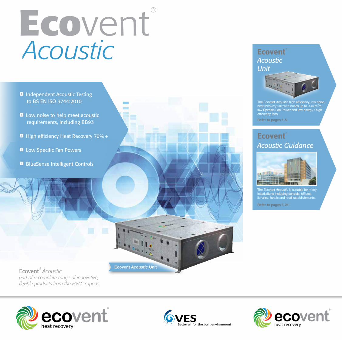
The Ecovent Acoustic high efficiency, low noise, heat recovery unit with duties up to 0.45 m3/s, low Specific Fan Power and low energy / high efficiency fans. Refer to pages 1-5.
Ecovent R
Acoustic Guidance
The Ecovent Acoustic is suitable for many installations including schools, offices, libraries, hotels and retail establishments.
Refer to pages 6-21.
Ecovent R
Acoustic
Ecovent R
Acoustic
part of a complete range of innovative,flexible products from the HVAC experts
f Independent Acoustic Testing to BS EN ISO 3744:2010 f Low noise to help meet acoustic requirements, including BB93
f High efficiency Heat Recovery 70% +
f Low Specific Fan Powers f BlueSense Intelligent Controls
R
Other products and services from the complete range of VES HVAC solutions:
Air Handling Units• Supply and extract, combined or separate. • Heat recovery including crossflow plate heat exchangers, thermal wheels and run-around coils. • Plantroom or weatherproof, flat or stacked. • Fitted silencers, inverters and controls. • Matching DX condensing units. • Various case constructions including EN 1886 certified units.
Duct Fans • In-line centrifugal, with forward or backward curved impellers. • Round, axial and mixed flow fans. • Fitted silencers available on all units. • Manual and automatic speed controllers available.
Twin Fans • For ceiling void, plantroom and weatherproof. • Many models and configurations. • Fitted auto-changeover system.
Roof Extract Units • Three ranges for volume and pressure. • Curb and soaker sheet bases.
Wall and Ceiling Fans • All types for commercial, industrial and domestic premises.
Kitchen Hood Extract Fans • Heavy duty high temperature fans for hot greasy air. • Motors out of airstream. • Single inlet fans, in-line and vertical jet roof units.
Control Panels • Off the shelf and built to order panels.• Air quality sensors and energy savers. • Intelligent control software. • A range of remotes including touch screen.
Noise Control • Matching silencers available for all ventilation products. • Silencers designed to meet noise criteria. • Cleanable silencers.• Weatherproof silencers.
Specialist Site Services • Plant refurbishment. • Energy saving upgrades. • Noise reduction. • Site surveys. • Kitchen ventilation. • AHU flat pack installation. • Maintenance. • Spares.
Ecovent Acoustic Unit
Ecovent R Acoustic
Applications
The Ecovent Acoustic is suitable for many installations including schools, offices,
libraries, hotels and retail establishments.
The unit has been independently acoustic tested to BS EN ISO 3744:2010 -
Determination of Sound Power Levels of noise sources, using sound pressure for
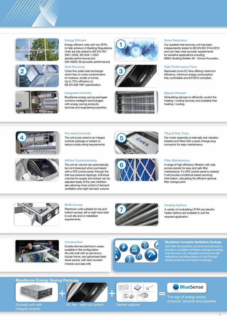
Pre-wired Controls The unit is pre-wired to an integral controls package or isolator to reduce onsite wiring requirements.
‘Plug & Play’ Fans Fan motor assembly is internally anti-vibration isolated and fitted with a quick change plug connector for easy maintenance.
ConstructionDouble skinned plantroom cases, available in flat configuration. All units built with an aluminium tubular frame, and galvanised steel sheet panels, with resin bonded mineral wool slab infill.
BlueSense Complete Ventilation Package VES offer the expertise, products and services to provide a complete ventilation package including heat recovery unit, integrated controls and site assistance, providing peace of mind through reliable products and expert knowledge.
Ecovent unit with integral controls
EC fan - with full control Sensor options
The sign of energy saving products, services and expertise
=BlueSense Energy Saving Package
Multi-Access Plantroom units suitable for top and bottom access, left or right hand side to suit site and or installation requirements.
Heating Options A variety of modulating LPHW and electric heater options are available to suit the required application.
Filter MaintenanceA range of high efficiency filtration with side access panels for easy and safe filter maintenance. If a VES control panel is ordered it will provide conditional based servicing information, calculating the efficient optional filter change point.
3
Energy Efficient Energy efficient units with low SFPs to help achieve L2 Building Regulations. Units are fully tested to BS EN ISO 5801:2008, BS 848-1:2007 (airside performance) and DIN 45635-38 (acoustic performance).
Noise Reduction Our quietest heat recovery unit has been independently tested to BS EN ISO 3744:2010 and can help meet acoustic requirements for sensitive applications including BB93; Building Bulletin 93 - School Acoustics.
High Performance Fans Backward curve EC fans offering maximum efficiency, minimum energy consumption, fully controlable and ErP2015 compliant.
Integrated Controls BlueSense energy saving packages combine intelligent technologies with energy saving products, services and engineering expertise.
Heat Recovery Cross flow plate heat exchanger which has no cross contamination of moisture, smells or fumes. Up to 75% efficiency to BS EN 308:1997 specification.
Bypass Damper Modulating damper to efficiently control the heating / cooling recovery and available free heating / cooling.
Airflow Commissioning The unit air volume can automatically be commissioned when purchased with a VES control panel, through the inlet eye pressure tappings. Individual volumes for supply and extract can be adjusted easily at the user interface also allowing more control of demand ventilation and night set back volume.
1
5
6
1
2
4
3
7
2 3
SIZE
2 -
EA
X244
-1
HigH EfficiEncy HEat rEcovEry unitsEcovent R
Acoustic our quiEtEst HEat rEcovEry unit
selection Dataunit size 2 EaX244-1
Size Phase Motor Size Voltage Fan Speed Full Load Current Speed Control
Air off temperature based upon entering air of -5 oC. Power = Air Volume x Constant x Temperature Rise. kW = m3/s x 1.21 x rT oC
Technical Data
Air Volumem3/s
MaximumLeaving Air
Temp oC
Maximum kWOutput
3ph - Electric Heater
ElectricThyristorHeating
0.1500.1750.2000.225
28.123.332.228.1
6.006.009.009.00
Heating and Control Options
0.250 24.8 9.00
1ph - Electric Heater
CPB0-1/6KW-1/P/CC/C
Electric Heater Control Panel Electric Heater Control Panel
EHEAX2/6KW/1X1
EHEAX2/9KW/1X1
Sound Spectrum dB re 10-12 W PWL CentreFrequency (Hz) Casing Noise BreakoutFan Speed
rpm
2270
2043
1816
1589
1362
6366
64
62
60
57
56
12568
66
64
61
58
57
25069
68
65
61
57
55
50070
67
64
61
57
54
1k70
67
63
60
55
53
2k68
65
62
57
53
50
4k63
60
56
51
47
43
8k55
53
49
44
37
32
NR @ 1m NR @ 3m33
32
29
25
20
18
26
25
22
18
13
11
FanVoltage
100%
90%
80%
70%
60%
63-1
125-6
250-11
500-24
1k-27
2k-30
4k-31
8k-28
Centre Frequency
Case Insertion Loss
63
-6
125
-11
250
-18
500
-22
1k
-25
2k
-17
4k
-22
8k
-20
Silencer Option
EAXVA200/1200/P
Sound Spectrum dB re 10-12 WPWL Centre Frequency (Hz)
LPHW coil, designed for LPHW 82/71 oC, EAT -5 oC, LAT 25 oC, coil construction copper tubes, aluminium fins, coil connections 1II BSP.Note: If no control panel is purchased the unit will be supplied with a main isolator.
Note: If no control panel is purchased the unit will be supplied with a main isolator.
Note: Each silencer will add a maximum of 30 Pa to the external resistance.
Note: Independently acoustic tested to BS EN ISO 3744:2010.
EAX244-1 / FP - WE
LTRT
Heating
null
/ RBLB
/
Controls
g4F7
/ ISCCPSC
EE /
Notes: SFP figures quoted at voltages tested in accordance with BS EN ISO 5801:2008, BS 848-1:2007 for each of the two fans. The fan performance is calculated using standard G4 filters. Alternative F7 will add a maximum of 150 Pa. NR levels are dependent upon environmental conditions. Tolerances: On flow rates: +/- 5% On acoustic power and pressure: Levels: +/- 3 dB By octave band: +/- 5 dB
Note: Data for design guidance only. for full details, outline drawings are available upon request. Note: Data for design guidance only. for full details, outline drawings are available upon request.
Induct Loss
4 5
Ecovent R controls Extended features
cPB range
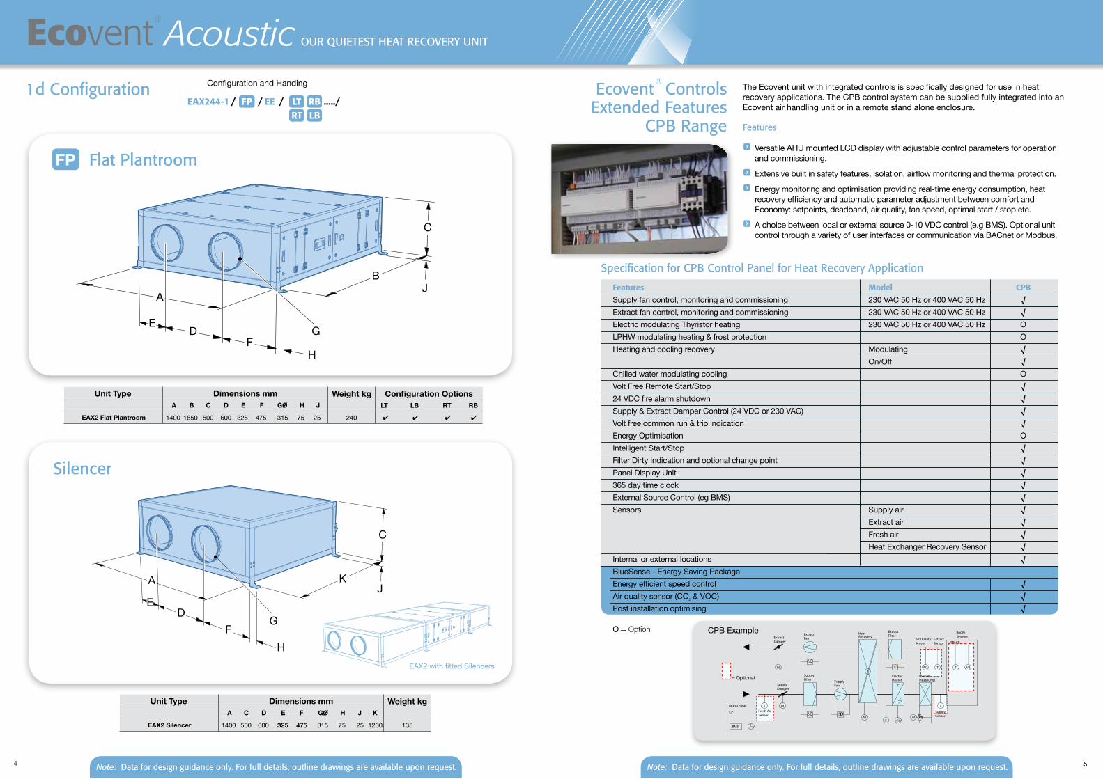
The Ecovent unit with integrated controls is specifically designed for use in heat recovery applications. The CPB control system can be supplied fully integrated into an Ecovent air handling unit or in a remote stand alone enclosure.
features
f Versatile AHU mounted LCD display with adjustable control parameters for operation and commissioning.
f Extensive built in safety features, isolation, airflow monitoring and thermal protection.
f Energy monitoring and optimisation providing real-time energy consumption, heat recovery efficiency and automatic parameter adjustment between comfort and Economy: setpoints, deadband, air quality, fan speed, optimal start / stop etc.
f A choice between local or external source 0-10 VDC control (e.g BMS). Optional unit control through a variety of user interfaces or communication via BACnet or Modbus.
specification for cPB control Panel for Heat recovery application Features Model CPB
Supply fan control, monitoring and commissioning 230 VAC 50 Hz or 400 VAC 50 Hz √Extract fan control, monitoring and commissioning 230 VAC 50 Hz or 400 VAC 50 Hz √Electric modulating Thyristor heating 230 VAC 50 Hz or 400 VAC 50 Hz OLPHW modulating heating & frost protection OHeating and cooling recovery Modulating √ On/Off √Chilled water modulating cooling OVolt Free Remote Start/Stop √24 VDC fire alarm shutdown √Supply & Extract Damper Control (24 VDC or 230 VAC) √Volt free common run & trip indication √Energy Optimisation OIntelligent Start/Stop √Filter Dirty Indication and optional change point √Panel Display Unit √365 day time clock √External Source Control (eg BMS) √Sensors Supply air √ Extract air √ Fresh air √ Heat Exchanger Recovery Sensor √Internal or external locations √BlueSense - Energy Saving Package Energy efficient speed control √Air quality sensor (CO2 & VOC) √Post installation optimising √ O= Option CPB Example
= Optional
p
p
M
T
M
T
M
p
p
M
T
T
AQ
S
ExtractFan
SupplyFan
ElectricHeater
SupplyFilter
ExtractFilter
HeatRecovery
CW/DXHeatpump
Control Panel
ExtractDamper
SupplyDamper
Air QualitySensor
ExtractSensor
Fresh AirSensor
RoomSensors
SupplySensor
AQ
SPACE
CP
BMS
flat PlantroomFP
DE
C
A
1d configuration
Dimensions mmUnit TypeA B C D E F GO H J
Weight kg
EAX2 Flat Plantroom 1400 1850 500 600 325 475 315
Configuration OptionsLT LB RT RB
240
Dimensions mm
4 4 4 4
silencer
Dimensions mmUnit TypeA C D E F GO H J K
Weight kg
EAX2 Silencer 1400 500 600 325 475 315 75 135
Dimensions mm
F
B
G
A
DF
K
C
EG
EAX2 with fitted Silencers
325 475 25 1200
EAX244-1 / FP / LTRT
RBLB
Configuration and Handing
H
J
H
J
75 25
...../FP EE/
Note: Data for design guidance only. for full details, outline drawings are available upon request. Note: Data for design guidance only. for full details, outline drawings are available upon request.
HigH EfficiEncy HEat rEcovEry unitsEcovent R
Acoustic our quiEtEst HEat rEcovEry unit
6 7
Acoustic Guidance
There is a greater awareness of ventilation noise issues across many situations, in particular for education applications via the Building Bulletin 93 - Acoustics for Schools. This is a key challenge for an HVAC manufacturer hoping to analyse and provide detailed information about something that is relative and subjective in nature. The complication of decibels, the usual confusion about volume, power and logarithmic scales all make it tricky for customers to know how a noise number translates into the user experience.
Along with the challenges of designing low noise products, comes accurately displaying the information in a meaningful way. Acoustic testing is important as it provides useful data about the noise emitted by our product, helping specifiers to make informed decisions when selecting our products for installation in real life applications.
Often a comparison is made between manufacturers, to determine who has the better unit and meets stated regulations. Therefore making the information concise, understandable and transparent is our number one aim.
In addition, we know that it is highly unlikely for most applications, where low noise is extremely important, that there will be one single solution. There is generally no direct relationship between room noise level and the sound level generated by the mechanical ventilation system. Alongside this, specifiers and designers have to find a balance between costs, energy, legislation and maintenance; sometimes generating conflicting issues.
It is always recommended to seek the expert advice of an acoustic specialist for noise sensitive applications.
Introduction
Definition of Sound (Noise)
f Sound is any pressure in the air that the human ear can detect f Noise is any sound that is undesirable by the recipient f The terminology of noise and sound are used interchangeably
Noise CategoriesAny moving or vibrating parts in a product can produce noise; this varies with the operation of the product. The noise is generated by the mechanical system i.e. the fan noise and can be classified into 5 categories:
Radiated from the air handling unit/fan, the noise is transmitted through the air and directly through walls, windows, doors or ceilings into adjoining spaces.
Case BreakoutThe first type of break out noise is generated by high speed or turbulent air in ducts that cause the duct walls to vibrate and radiate a low frequency noise. The second is low frequency noise from a remote source, such as a fan in the AHU and can traverse down the duct into spaces or breaks out through the case or ductwork itself.
1
2
Duct-borneOriginated at a noise-generating source (i.e. the fan) the noise is carried down the ducted air path to receivers in rooms located remote from the source.
3
Self-generatedProduced as air moves through a confined duct system, noise is generated at points of turbulence such as dampers, elbows, t-junctions and air terminal devices. Self-generated noise increases with air velocity and the number of turbulent air points within a system.
4
Structure-borneGenerated from rotating or vibrating equipment such as framework or doors, which vibrates part of a building.
5
Noise f Noise produced might be broadband, containing sound energy in several frequency bands, but no audibly distinct components in one frequency band. f Noise that whines or hums at particular frequencies can produce an audible tone that can be annoying to the receiver. f In ventilation the rotational fan speed causes an annoying low frequency hum between 100-250 Hz known as fan ‘Blade Pass Frequency’. f The fan ‘Blade Pass Frequency’ noise can be very intense - varying with the number of blades and rotation velocity. f Understanding the noise sources and frequency pitches allows for a better understanding of how that particular noise will be transmitted in a real application.
Airborne
8 9
Acoustic Guidance
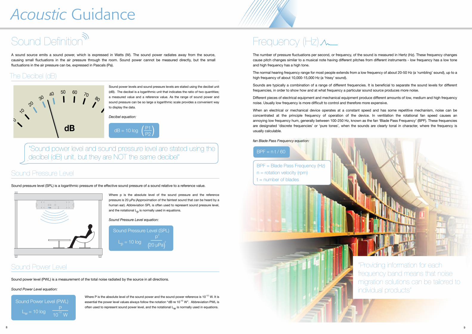
A sound source emits a sound power, which is expressed in Watts (W). The sound power radiates away from the source, causing small fluctuations in the air pressure through the room. Sound power cannot be measured directly, but the small fluctuations in the air pressure can be, expressed in Pascals (Pa).
Sound Definition
Where p is the absolute level of the sound pressure and the reference pressure is 20 µPa (Approximation of the faintest sound that can be heard by a human ear). Abbreviation SPL is often used to represent sound pressure level, and the notational Lp is normally used in equations.
Sound Pressure Level equation:
Sound Pressure Level
Where P is the absolute level of the sound power and the sound power reference is 10-12 W. It is essential the power level values always follow the notation “dB re 10-12 W”. Abbreviation PWL is often used to represent sound power level, and the notational Lw is normally used in equations.
Sound Power Level
“Sound power level and sound pressure level are stated using the decibel (dB) unit, but they are NOT the same decibel”
Sound power levels and sound pressure levels are stated using the decibel unit (dB). The decibel is a logarithmic unit that indicates the ratio of two quantities; a measured value and a reference value. As the range of sound power and sound pressure can be so large a logarithmic scale provides a convenient way to display the data.
Decibel equation:
The Decibel (dB)
dB
0
1020
3040 50 60 70
8090
100
110
dB = 10 log
Sound Pressure Level (SPL)
Lp = 10 log
Frequency (Hz)The number of pressure fluctuations per second, or frequency, of the sound is measured in Hertz (Hz). These frequency changes cause pitch changes similar to a musical note having different pitches from different instruments - low frequency has a low tone and high frequency has a high tone. The normal hearing frequency range for most people extends from a low frequency of about 20-50 Hz (a ‘rumbling’ sound), up to a high frequency of about 10,000-15,000 Hz (a ‘hissy’ sound). Sounds are typically a combination of a range of different frequencies. It is beneficial to separate the sound levels for different frequencies, in order to show how and at what frequency a particular sound source produces more noise. Different pieces of electrical equipment and mechanical equipment produce different amounts of low, medium and high frequency noise. Usually low frequency is more difficult to control and therefore more expensive. When an electrical or mechanical device operates at a constant speed and has some repetitive mechanism, noise can be concentrated at the principle frequency of operation of the device. In ventilation the rotational fan speed causes an annoying low frequency hum, generally between 100-250 Hz, known as the fan ‘Blade Pass Frequency’ (BPF). These frequencies are designated ‘discrete frequencies’ or ‘pure tones’, when the sounds are clearly tonal in character, where the frequency is usually calculable.
fan Blade Pass Frequency equation:
“Providing information for each frequency band means that noise migration solutions can be tailored to individual products”
BPF = n t / 60
BPF = Blade Pass Frequency (Hz)n = rotation velocity (rpm)t = number of blades
Sound pressure level (SPL) is a logarithmic pressure of the effective sound pressure of a sound relative to a reference value.
( 20 µPa
2
(
Sound power level (PWL) is a measurement of the total noise radiated by the source in all directions.
Sound Power Level equation:
P1P2( (
2
Sound Power Level (PWL)
Lw = 10 log 10 W-12
p
P
10 11
Acoustic Testing
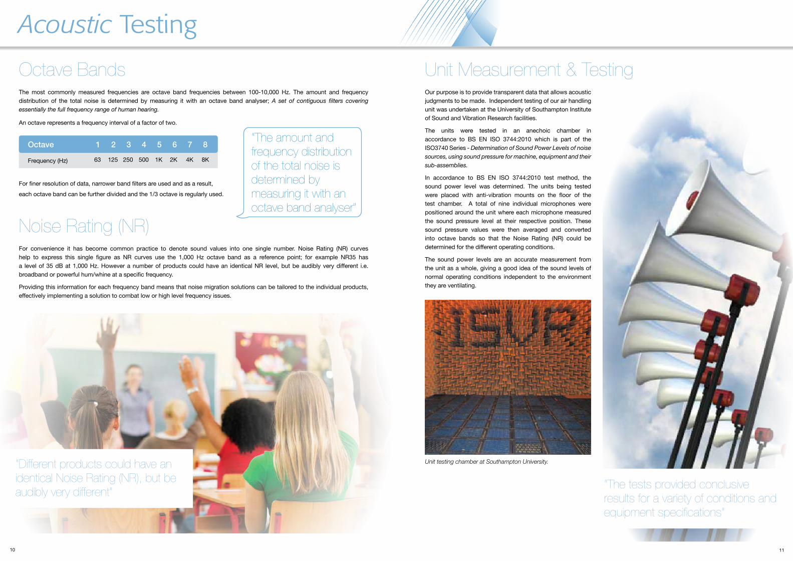
The most commonly measured frequencies are octave band frequencies between 100-10,000 Hz. The amount and frequency distribution of the total noise is determined by measuring it with an octave band analyser; A set of contiguous filters covering essentially the full frequency range of human hearing.
An octave represents a frequency interval of a factor of two.
For finer resolution of data, narrower band filters are used and as a result,each octave band can be further divided and the 1/3 octave is regularly used.
Octave Bands
“The amount and frequency distribution of the total noise is determined by measuring it with an octave band analyser”
Noise Rating (NR)For convenience it has become common practice to denote sound values into one single number. Noise Rating (NR) curves help to express this single figure as NR curves use the 1,000 Hz octave band as a reference point; for example NR35 has a level of 35 dB at 1,000 Hz. However a number of products could have an identical NR level, but be audibly very different i.e. broadband or powerful hum/whine at a specific frequency. Providing this information for each frequency band means that noise migration solutions can be tailored to the individual products, effectively implementing a solution to combat low or high level frequency issues.
Our purpose is to provide transparent data that allows acoustic judgments to be made. Independent testing of our air handling unit was undertaken at the University of Southampton Institute of Sound and Vibration Research facilities. The units were tested in an anechoic chamber in accordance to BS EN ISO 3744:2010 which is part of the ISO3740 Series - Determination of Sound Power Levels of noise sources, using sound pressure for machine, equipment and their sub-assemblies. In accordance to BS EN ISO 3744:2010 test method, the sound power level was determined. The units being tested were placed with anti-vibration mounts on the floor of the test chamber. A total of nine individual microphones were positioned around the unit where each microphone measured the sound pressure level at their respective position. These sound pressure values were then averaged and converted into octave bands so that the Noise Rating (NR) could be determined for the different operating conditions. The sound power levels are an accurate measurement from the unit as a whole, giving a good idea of the sound levels of normal operating conditions independent to the environment they are ventilating.
Unit Measurement & Testing
Unit testing chamber at Southampton University.
“The tests provided conclusive results for a variety of conditions and equipment specifications”
Octave
Frequency (Hz)
1 2 3 4 5 6 7 8
63 125 250 500 1K 2K 4K 8K
“Different products could have an identical Noise Rating (NR), but be audibly very different”
12 13
Acoustic Results
ResultsInitial results suggested that the noise sources within our range of products generated a higher and unwanted power level in the 100-250 Hz range, this is directly related to the fan ‘Blade Pass Frequency’. Once this was understood and the problematic frequency identified, it allowed us to experiment with the design of the product to reduce the sound power generated and reduce the sound migration through the case, this included assessing:
Heat
Rec
over
y E
cien
cy- %
ffi
Sound Spectrum dB re 10-12 W PWL CentreFrequency (Hz) Casing Noise BreakoutFan Speed
rpm
2270
2043
1816
1589
1362
6366
64
62
60
57
56
12568
66
64
61
58
57
25069
68
65
61
57
55
50070
67
64
61
57
54
1k70
67
63
60
55
53
2k68
65
62
57
53
50
4k63
60
56
51
47
43
8k55
53
49
44
37
32
NR @ 1m NR @ 3m33
32
29
25
20
18
26
25
22
18
13
11
FanVoltage
100%
90%
80%
70%
60%
63 125 250 500 1k 2k 4k 8kCentre Frequency
Case Insertion Loss
125050%
37
35
33
29
25
24
30
29
26
22
19
17
dBA @ 1m dBA @ 3m
Note: Independently acoustic tested to BS EN ISO 3744:2010.
Noise Data
Air Volume - 0.25 m3/s
Resistance - 150 Pa
Fan Speed - 80%
Specific Fan Power - 0.8 W/l/s for each fan - 1.6 W/l/s for the system
Heat Recovery Efficiency - 70%
Unit Performance
Sound power level, sound pressure level or a sound insulation quantity such as sound reduction index or insertion loss.
dB or dBA unit.
In the case of sound pressure levels the distance the measurement was carried out at typically 1m, 3m or 10m. Note sound power levels are stated independently of distance from source.
The test standard used to carry out the measurements and the installation and test conditions that measurements were carried out for.
Parameter Description
Noise Level Description
Measurement Unit
Distance
Test Standard
Noise Level
Mode of Operation
The overall noise level and noise level in each one-third octave band centre frequency.
The noise level at each operation of the product (e.g. different fan speed). If the noise level for only one mode of operation is given then the operating condition should be clearly stated.
1
2
3
4
5
6
Ideally, acoustic data should provide as much information as possible about the results, measurements and associated standards. It also has the added advantage of making accurate comparisons between products.
Acoustic results for the Ecovent Acoustic unit:
23
12
56
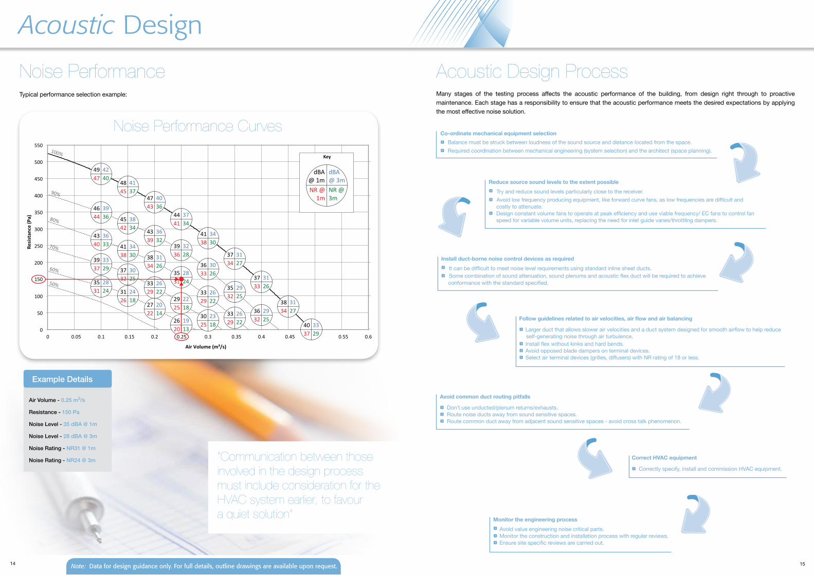
Typical performance selection example:
Example Details-1 -6 -11 -24 -27 -30 -31 -28
Duty Performance Curves
Note: Data for design guidance only. for full details, outline drawings are available upon request. Note: Data for design guidance only. for full details, outline drawings are available upon request.
4
Case Construction Acoustic MaterialFan Cradle Design
14 15
Acoustic Design
Noise Performance Acoustic Design Process Many stages of the testing process affects the acoustic performance of the building, from design right through to proactive maintenance. Each stage has a responsibility to ensure that the acoustic performance meets the desired expectations by applying the most effective noise solution.
Co-ordinate mechanical equipment selection f Balance must be struck between loudness of the sound source and distance located from the space. f Required coordination between mechanical engineering (system selection) and the architect (space planning).
Reduce source sound levels to the extent possible f Try and reduce sound levels particularly close to the receiver. f Avoid low frequency producing equipment, like forward curve fans, as low frequencies are difficult and costly to attenuate. f Design constant volume fans to operate at peak efficiency and use viable frequency/ EC fans to control fan speed for variable volume units, replacing the need for inlet guide vanes/throttling dampers.
Install duct-borne noise control devices as required f It can be difficult to meet noise level requirements using standard inline sheet ducts. f Some combination of sound attenuation, sound plenums and acoustic flex duct will be required to achieve conformance with the standard specified.
Follow guidelines related to air velocities, air flow and air balancing f Larger duct that allows slower air velocities and a duct system designed for smooth airflow to help reduce self-generating noise through air turbulence. f Install flex without kinks and hard bends. f Avoid opposed blade dampers on terminal devices. f Select air terminal devices (grilles, diffusers) with NR rating of 18 or less.
Avoid common duct routing pitfalls f Don’t use unducted/plenum returns/exhausts. f Route noise ducts away from sound sensitive spaces. f Route common duct away from adjacent sound sensitive spaces - avoid cross talk phenomenon.
Correct HVAC equipment f Correctly specify, install and commission HVAC equipment.
Monitor the engineering process f Avoid value engineering noise critical parts. f Monitor the construction and installation process with regular reviews. f Ensure site specific reviews are carried out.
Typical performance selection example:
Air Volume - 0.25 m3/s
Resistance - 150 Pa
Noise Level - 35 dBA @ 1m
Noise Level - 28 dBA @ 3m
Noise Rating - NR31 @ 1m
Noise Rating - NR24 @ 3m
Example Details
Noise Performance Curves
Note: Data for design guidance only. for full details, outline drawings are available upon request.
“Communication between those involved in the design process must include consideration for the HVAC system earlier, to favour a quiet solution”
16 17ves.co.uk
inspire create working environments
The environment surrounding the sound source will affect how sound power radiates away from the source, also sound pressure will vary within the environment, as when sound reaches a surface it will either reflect or absorb - but probably a mixture of both.
If sound is reflected then the pressure measurement will include both the source sound energy and the reflected sound energy.
If the same sound source, emitting identical sound power is in a different environment the sound pressure within the space will be different.
Understanding sound power emitted from the product and the type of environment allows for an accurate interpretation of acoustic data.
Environment
office application
school application
Classroom ves.co.uk
Ecovent Acoustic(EAX)UnitSpecification
The Ecovent Acoustic is suitable for many installations including schools, offices, libraries, hotels and retail establishments. The unit has been independently acoustic tested to BS EN ISO 3744:2010 - Determination of Sound Power Levels of noise sources, using sound pressure for machine, equipment and their sub-assemblies. Ecovent Acoustic - low noise heat recovery ideal for noise sensitive applications:
f Low noise to meet acoustic requirements, including BB93
f Independent acoustic testing to BS EN ISO 3744:2010
f Up to 75% heat recovery efficiency and modulating damper to control heating / cooling recovery
f Duties up to 0.45 m3/s
f 50mm tube and panel with acoustic infill
f 500mm in height
f NR35 at full speed
f High efficiency fans with low SFPs to achieve L2 Building Regulations
f Inbuilt BlueSense intelligent controls technology for performance and efficiency
f Variety of options to suit unit requirements
f Quick change plug connections for easy electrical maintenance
f Multi access plantroom units with top, bottom, left or right access
f Automatic air volume commissioning
f Conditional based servicing, calculating the efficient optimal filter change point.
R
Boardroom / Offices
library application
Library
Acoustic Applications
... ...
18 19
Acoustic Solutions
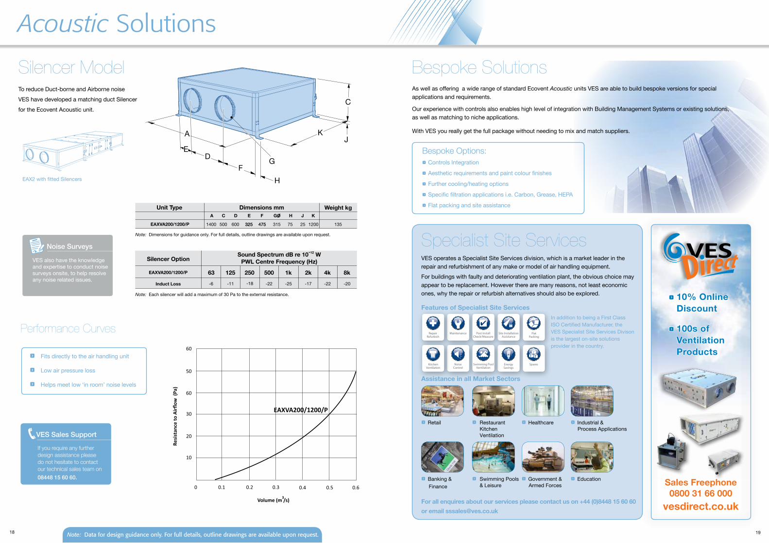
Bespoke SolutionsSilencer ModelTo reduce Duct-borne and Airborne noiseVES have developed a matching duct Silencerfor the Ecovent Acoustic unit.
Features of Specialist Site Services
Specialist Site ServicesVES operates a Specialist Site Services division, which is a market leader in the repair and refurbishment of any make or model of air handling equipment. For buildings with faulty and deteriorating ventilation plant, the obvious choice may appear to be replacement. However there are many reasons, not least economic ones, why the repair or refurbish alternatives should also be explored.
Dimensions mmUnit TypeA C D E F GO H J K
Weight kg
EAXVA200/1200/P 1400 500 600 325 475 315 75 135
Dimensions mm
A
DF
K
C
EG
EAX2 with fitted Silencers
325 475 25 1200
H
J
VES Sales Support
If you require any further design assistance please do not hesitate to contact our technical sales team on 08448 15 60 60.
As well as offering a wide range of standard Ecovent Acoustic units VES are able to build bespoke versions for special applications and requirements. Our experience with controls also enables high level of integration with Building Management Systems or existing solutions, as well as matching to niche applications. With VES you really get the full package without needing to mix and match suppliers.
Bespoke Options: f Controls Integration
f Aesthetic requirements and paint colour finishes
f Further cooling/heating options
f Specific filtration applications i.e. Carbon, Grease, HEPA
f Flat packing and site assistance
vesdirect.co.uk
f Retail f Restaurant Kitchen Ventilation
f Industrial & Process Applications
f Healthcare
Assistance in all Market Sectors
Volume (m /s)
EAXVA200/1200/P
Resi
stan
ce to
Airfl
ow (
Pa)
10
20
30
50
60
60
0.10 0.2 0.3 0.4 0.5 0.6
3
f Fits directly to the air handling unit f Low air pressure loss f Helps meet low ‘in room’ noise levels
Noise Surveys
VES also have the knowledge and expertise to conduct noise surveys onsite, to help resolve any noise related issues.
Performance Curves
f Banking & Finance
f Swimming Pools & Leisure
f Educationf Government & Armed Forces
In addition to being a First Class ISO Certified Manufacturer, the VES Specialist Site Services Divison is the largest on-site solutions provider in the country.
f 10% Online Discount
f 100s of Ventilation Products
Sales Freephone 0800 31 66 000
For all enquires about our services please contact us on +44 (0)8448 15 60 60or email [email protected]
Note: Dimensions for guidance only. For full details, outline drawings are available upon request.
Note: Data for design guidance only. for full details, outline drawings are available upon request.
63
-6
125
-11
250
-18
500
-22
1k
-25
2k
-17
4k
-22
8k
-20
Silencer Option
EAXVA200/1200/P
Sound Spectrum dB re 10-12 WPWL Centre Frequency (Hz)
Note: Each silencer will add a maximum of 30 Pa to the external resistance.
Induct Loss
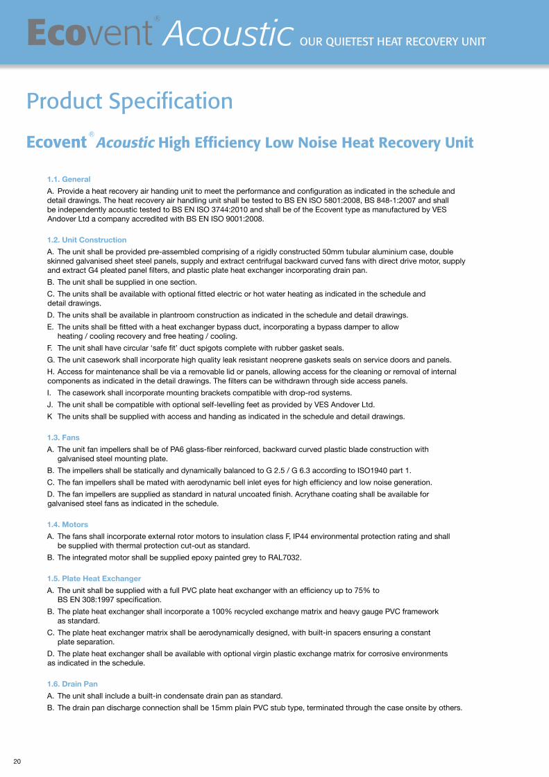
Ecovent R Acoustic High Efficiency Low Noise Heat Recovery Unit
1.1. GeneralA. Provide a heat recovery air handing unit to meet the performance and configuration as indicated in the schedule and detail drawings. The heat recovery air handling unit shall be tested to BS EN ISO 5801:2008, BS 848-1:2007 and shall be independently acoustic tested to BS EN ISO 3744:2010 and shall be of the Ecovent type as manufactured by VES Andover Ltd a company accredited with BS EN ISO 9001:2008. 1.2. Unit ConstructionA. The unit shall be provided pre-assembled comprising of a rigidly constructed 50mm tubular aluminium case, double skinned galvanised sheet steel panels, supply and extract centrifugal backward curved fans with direct drive motor, supply and extract G4 pleated panel filters, and plastic plate heat exchanger incorporating drain pan.B. The unit shall be supplied in one section.C. The units shall be available with optional fitted electric or hot water heating as indicated in the schedule and detail drawings.D. The units shall be available in plantroom construction as indicated in the schedule and detail drawings.E. The units shall be fitted with a heat exchanger bypass duct, incorporating a bypass damper to allow heating / cooling recovery and free heating / cooling.F. The unit shall have circular ‘safe fit’ duct spigots complete with rubber gasket seals.G. The unit casework shall incorporate high quality leak resistant neoprene gaskets seals on service doors and panels.H. Access for maintenance shall be via a removable lid or panels, allowing access for the cleaning or removal of internal components as indicated in the detail drawings. The filters can be withdrawn through side access panels.I. The casework shall incorporate mounting brackets compatible with drop-rod systems.J. The unit shall be compatible with optional self-levelling feet as provided by VES Andover Ltd.K The units shall be supplied with access and handing as indicated in the schedule and detail drawings. 1.3. FansA. The unit fan impellers shall be of PA6 glass-fiber reinforced, backward curved plastic blade construction with galvanised steel mounting plate.B. The impellers shall be statically and dynamically balanced to G 2.5 / G 6.3 according to ISO1940 part 1.C. The fan impellers shall be mated with aerodynamic bell inlet eyes for high efficiency and low noise generation.D. The fan impellers are supplied as standard in natural uncoated finish. Acrythane coating shall be available for galvanised steel fans as indicated in the schedule. 1.4. MotorsA. The fans shall incorporate external rotor motors to insulation class F, IP44 environmental protection rating and shall be supplied with thermal protection cut-out as standard.B. The integrated motor shall be supplied epoxy painted grey to RAL7032. 1.5. Plate Heat ExchangerA. The unit shall be supplied with a full PVC plate heat exchanger with an efficiency up to 75% to BS EN 308:1997 specification.B. The plate heat exchanger shall incorporate a 100% recycled exchange matrix and heavy gauge PVC framework as standard.C. The plate heat exchanger matrix shall be aerodynamically designed, with built-in spacers ensuring a constant plate separation.D. The plate heat exchanger shall be available with optional virgin plastic exchange matrix for corrosive environments as indicated in the schedule. 1.6. Drain PanA. The unit shall include a built-in condensate drain pan as standard.B. The drain pan discharge connection shall be 15mm plain PVC stub type, terminated through the case onsite by others.
Product specification
20
HigH EfficiEncy HEat rEcovEry unitsEcovent R
Acoustic our quiEtEst HEat rEcovEry unit
Ecovent R AcousticEcovent has been the acknowledged market leader in heat recovery air handling units for over 10 years. The new high efficiency, low noise, heat recovery unit with duties up to 0.45 m3/s, low Specific Fan Power and low energy / high efficiency fans is the ideal solution for noise sensitive areas.
The Ecovent Acoustic is suitable for many installations including schools, offices, libraries, hotels and retail establishments. Designed to fit any application, the unit has been independently acoustic tested to BS EN ISO 3744:2010.
Energy SavingIntelligent Controls enhance performance whilst saving energy and money
1.7. FiltrationA. The filters shall be 100mm pleated filter media as standard, with rigid wax treated cardboard moisture resistant frame.B. Filters shall be to BS EN 779 Classification Grade G4 as standard, grade as indicated in the schedule and detail drawings. F7 alternative available.
1.8. HeatingA. The units shall be available with hot water or electric element heating as indicated in the schedule and detail drawings.B. The hot water heater battery shall be of copper tube, aluminium fin block construction, with galvanised sheet steel casework. The flow and return pipe connections shall be handed as indicated in the schedule and detail drawings.C. The hot water heater battery shall be available with alternative fin coatings by special order, as indicated in the schedule.D. The electric heater battery shall be suitable for single or three phase supply and compatible with thyristor control as indicated in the schedule and detail drawings.E. The electric heater battery shall consist of an element array sized to suit the steps and phases as indicated in the schedule and detail drawings. The elements shall consist of a tubular incoloy shroud containing compressed magnesium oxide powder packed around a Nickel Chromium resistance wire. The element array shall be evenly spread across the open area of the duct.F. Where multiple elements are required to achieve the steps and phases as indicated in the schedule, elements shall be linked by copper busbar or terminated with electrical connectors.G. The electric heater battery shall be fitted as standard with a 130 °C non-adjustable thermal safety cutout, with manual reset.H. All electric heaters shall be 1500 V flash tested, and resistance tested for correct component assembly. Test certificates shall be available on request.
1.9. Operation EnvironmentA. The unit shall be designed to operate in ambient temperatures from -20 °C up to 40 °C, and can run continuously at up to 80% humidity level.
2.0. ControlsA. The unit shall be fitted as standard with EC or Inverter fan speed control system to match fan type with max/min speed and 0-10 v BMS control, i.e Air Quality or Temperature sensor.B. The unit shall be available with optional unit mounted CPB control panel as manufactured and factory fitted by VES Andover Ltd. to suit electric or hot water heating, or alternative loose CPB panel for installation by others. If no control panel is ordered the unit will be supplied with local isolator for unit mains connections.C. Fitted Controls shall be positioned as indicated in the schedule and detail drawings.D. Controls shall be supplied with internally mounted circuit breakers, run, trip and panel live indication and lockable door isolation switch.E. Control panels shall have individual circuit breakers for Supply, Extract, Control and Electric Heater Battery where indicated in the schedule and detail drawings.F. Fitted controls shall be supplied with a supply air duct sensor to be fitted on-site by others as indicated in the schedule.G. Fitted controls shall be supplied with a wired AHU mounted LCD controller. Optional room user interfaces are available.H. Fitted controls shall be fully pre-wired to internal components. Hot water controls shall be pre wired to a local junction box for easy electrical connection to optional four port valve actuator supplied by VES Andover LTD as indicated in the schedule.
2.1 AncillariesA. The unit shall be fully compatible with a standard range of spigot mounted silencers. The silencers shall be suitable for direct mounting to the unit.B. The silencer shall be a rigidly constructed 50mm double skinned galvanised sheet steel case lining incorporating internal splitting vanes lined with resin bonded mineral wool.C. The silencer casework shall be provided naturally finished in high quality galvanised steel as standard. Internal and external powder coat available as indicated in the schedule. Colour to be in accordance with schedule.
Download specification from www.ves.co.uk/information-centre
21
P
rod
uct
FanTypeTT
Unit
Size
FanSize
Phase
U
nitConfi
g
Main
Heating
Infi
ll
Handing
Main
Filter Control
Panel Section
EAX
/FP
44
-1
[null]
/E
E
/RT
/G
4 /IS
C
-E
/RB
/F7
/CP
SC
-W
/LT
/LB
Prod
uct
EA
X
Unit Config
/FP= Flat P
lantroom
Main
Heating
-E=E
lectric Heating
-W=W
ater Heating
nfill
EE
(50mm
)
Handing
/RT=
Right Top
/RB
=R
ight Bottom
/LT=Left Top
/LB=
Left Bottom
Main Filter
/G4
/F7
ControlPanel Section
/ISC
=Isolator and
built in
Sp
eed C
ontrol
/CP
SC
=C
ontrol Panel and
b
uilt in Sp
eed C
ontrol
Options
Case ConstructionEcovent
Acousticc
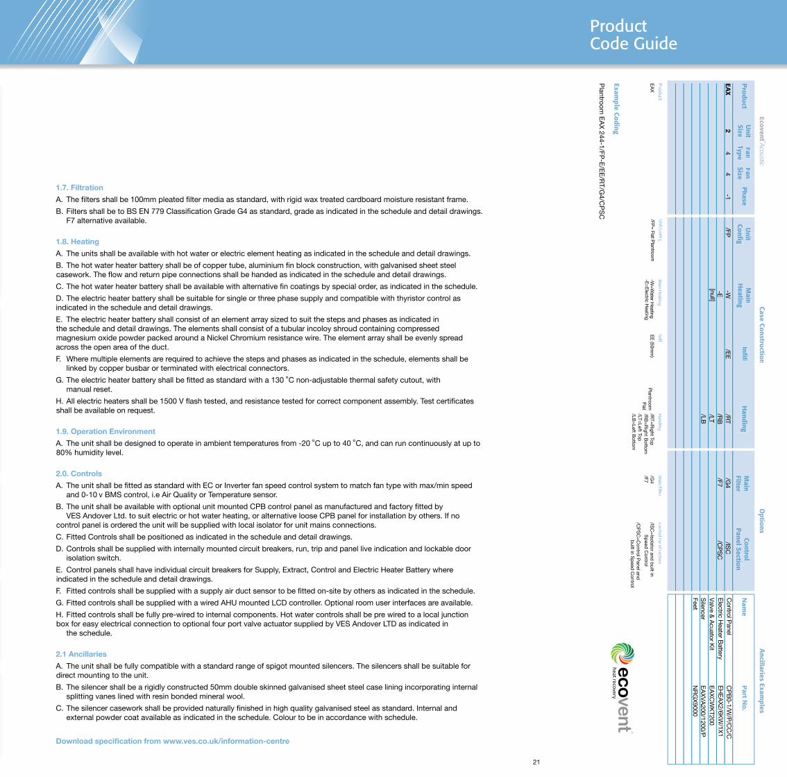
Example Coding
Plantroom
EA
X 244-1/FP
-E/E
E/R
T/G4/C
PS
C
Plantroom
Flat
RAA
Nam
et N
o.Part
Electric H
eater Battery
EH
EA
X2/6K
W/1X
1V
alve & A
cuator Kit
Silencer
EA
XC
WK
T200E
AX
VA
200/1200/P
Control P
anelC
PB
0-1/W/P
/CC
/C
FeetN
RG
X9000
Ancillaries Exam
plesA
2
HIgH EFFICIENCy HEAT RECOvERy uNITSEcovent R
Acoustic OuR quIETEST HEAT RECOvERy uNIT Product Code guide
Why choose vESVES has been supplying products for the HVAC industry for over 40 years, and have the in-depth knowledge and resources to provide solutions to all ventilation related requirements. We are asubstantial British manufacturing company with over 250 employees, several factories plus aregional base in the north of England, and sales engineers located throughout the UK.
Complete range of productsThe product range encompasses all types of ventilation products, including those required for commercial, industrial, public and domestic buildings. The emphasis is on low energyproducts and sophisticated controls to meet Building Regulation requirements. The range extends from a small bathroom extract fan up to large bespoke air handling units. There are specialist heat recovery units; high temperature fans for kitchen hood extract; duct, wall, ceiling and roof units; low noise products, silencers and fitted controls.
High quality, flexible solutionsVES operates a quality assurance system to ISO 9001, monitored by the BSI. The air movement products are tested in-house to BS EN ISO 5801:2008, BS 848-1:2007 and submitted for external testing and approval when necessary. VES specialise in bespoke designs for ventilation units. Whatever the issue, be it space, noise or temperature, VES can provide a design solution to meet the requirements of the project.
Superior customer serviceFrom the moment we receive your enquiry, to delivery and beyond; we have the people in place to give excellent customer service. The VES after sales service covers the whole of the UK and is among the best in the industry.
Experience and expertiseVES employs a range of experts in disciplines including: air movement, noise control, air conditioning, controls, electrics and product refurbishment, and we have key staff who have worked at VES for many years.
Manufactured in the uKVES has over 12000m2 of manufacturing and stores space, and has state of the art sheet metalworking equipment, plus a large powder coating plant. VES also has a substantial controls department, and makes components such as dampers and electric heaters in-house. This not only provides employment for localpeople, but also many suppliers around the UK.
Optimum PerformanceOur quietest heat recovery unit, meeting regulations and maximising performance. Energy saving packages combine intelligent controls technology, products and services.
Simple Installation and MaintenanceSimple connection and pre-installed features save on site costs and reduce lead times. Carefully designed maintenance features minimise downtime and total cost of ownership.
Robust ConstructionExcellent build quality ensures minimal noise breakout, low SFPs and air tight performance.
versatile OptionsVersatile location, handing and access options meet the widest range of project requirements.
Ecovent
Acoustic Features and Benefits
Energy SavingIntelligent Controls enhance performance whilst saving energy and money.
R
2
4
1
76
35
R
Air QualityCaseConstruction
DemandVentilation
EnergyE�cient Fans
Filters
Plug & Play
Prewired/FittedControls
SpeedControl
ThyristorHeater
Humidity Temperature HeatRecovery
R
Ecovent R
Acoustic Unit
The Ecovent Acoustic high efficiency, low noise, heat recovery unit with duties up to 0.45 m3/s, low Specific Fan Power and low energy / high efficiency fans. Refer to pages 1-5.
Ecovent R
Acoustic Guidance
The Ecovent Acoustic is suitable for many installations including schools, offices, libraries, hotels and retail establishments.
Refer to pages 6-21.
Ecovent R
Acoustic
Ecovent R
Acoustic
part of a complete range of innovative,flexible products from the HVAC experts
f Independent Acoustic Testing to BS EN ISO 3744:2010 f Low noise to help meet acoustic requirements, including BB93
f High efficiency Heat Recovery 70% +
f Low Specific Fan Powers f BlueSense Intelligent Controls
R
Other products and services from the complete range of VES HVAC solutions:
Air Handling Units• Supply and extract, combined or separate. • Heat recovery including crossflow plate heat exchangers, thermal wheels and run-around coils. • Plantroom or weatherproof, flat or stacked. • Fitted silencers, inverters and controls. • Matching DX condensing units. • Various case constructions including EN 1886 certified units.
Duct Fans • In-line centrifugal, with forward or backward curved impellers. • Round, axial and mixed flow fans. • Fitted silencers available on all units. • Manual and automatic speed controllers available.
Twin Fans • For ceiling void, plantroom and weatherproof. • Many models and configurations. • Fitted auto-changeover system.
Roof Extract Units • Three ranges for volume and pressure. • Curb and soaker sheet bases.
Wall and Ceiling Fans • All types for commercial, industrial and domestic premises.
Kitchen Hood Extract Fans • Heavy duty high temperature fans for hot greasy air. • Motors out of airstream. • Single inlet fans, in-line and vertical jet roof units.
Control Panels • Off the shelf and built to order panels.• Air quality sensors and energy savers. • Intelligent control software. • A range of remotes including touch screen.
Noise Control • Matching silencers available for all ventilation products. • Silencers designed to meet noise criteria. • Cleanable silencers.• Weatherproof silencers.
Specialist Site Services • Plant refurbishment. • Energy saving upgrades. • Noise reduction. • Site surveys. • Kitchen ventilation. • AHU flat pack installation. • Maintenance. • Spares.
Ecovent Acoustic Unit
Ecovent R Acoustic
Applications
The Ecovent Acoustic is suitable for many installations including schools, offices,
libraries, hotels and retail establishments.
The unit has been independently acoustic tested to BS EN ISO 3744:2010 -
Determination of Sound Power Levels of noise sources, using sound pressure for