VHDL Tutori al..................................................... Error! Bookmark not defined. 1. Intr oducti on ..................................................................................................... 1 2. Level s of representation and abstrac tion .......................................................... 2 3. Basic Structure of a VHDL fil e........................................................................ 3 Behavi oral model ............................................................................................ 6 Concur rency .................................................................................................... 8 Struc tural descripti on ...................................................................................... 8 4. Lexi cal Elements of VHDL ........................................................................... 13 5. Data Objects: Signals, Variables and Constants ............................................. 16 Consta nt ........................................................................................................ 16 Vari able ........................................................................................................ 16 Signal ............................................................................................................ 17 6. Data types ..................................................................................................... 18 Intege r types .................................................................................................. 20 Floati ng-poi nt types ....................................................................................... 21 Physi cal types ................................................................................................ 21 Array Type ............................... ..................................................................... 23 Record Type .................................................................................................. 25 Signal attrib utes............................................................................................. 27 Scalar attri butes ............................................................................................. 28 Array attributes ............................................................................................. 28 7. Opera tors................................ ....................................................................... 29 8. Behavioral Modeling: Sequential Statements ................................................. 34 Basi c Loop sta temen t .................................................................................... 40 Whil e-Loop sta tement ................................................................................... 41 For-Loop statement ....................................................................................... 41 9. Dataflow Modeling ± Concurrent Statements ................................................ 45 10. Struc tural Modeling ..................................................................................... 49 11. Ref erences................................................................................................... 52 Appendix: IEEE Standard Package STD_LOGIC_1164________________________________________________________________________This tutorial gives a brief overview of the VHDL language and is mainly intended as a companion for the Digital Design Laboratory . This writing aims to give the reader a quickintroduction to VHDL and to give a complete or in-depth discussion of VHDL. For a more detailed treatment, please consult any of the many good books on this topic. Several ofthese books are listed in the re ference list. 1. Introduction
VHDL Tutorial.....................................................Error! Bookmark not defined. 1. Introduction ..................................................................................................... 1 2. Levels of representation and abstraction .......................................................... 2
3. Basic Structure of a VHDL file........................................................................ 3 Behavioral model ............................................................................................ 6 Concurrency .................................................................................................... 8 Structural description ...................................................................................... 8
4. Lexical Elements of VHDL ........................................................................... 13 5. Data Objects: Signals, Variables and Constants ............................................. 16
Constant ........................................................................................................ 16 Variable ........................................................................................................ 16 Signal ............................................................................................................ 17
6. Data types ..................................................................................................... 18 Integer types .................................................................................................. 20 Floating-point types ....................................................................................... 21 Physical types ................................................................................................ 21 Array Type .................................................................................................... 23 Record Type .................................................................................................. 25 Signal attributes ............................................................................................. 27 Scalar attributes ............................................................................................. 28 Array attributes ............................................................................................. 28
This tutorial gives a brief overview of the VHDL language and is mainly intended as acompanion for the Digital Design Laboratory. This writing aims to give the reader a quick introduction to VHDL and to give a complete or in-depth discussion of VHDL. For a moredetailed treatment, please consult any of the many good books on this topic. Several of these books are listed in the reference list.
VHDL stands for VHSIC (Very High Speed Integrated Circuits)Hardware Description
Language. In the mid-1980¶s the U.S. Department of Defense and the IEEE sponsored thedevelopment of this hardware description language with the goal to develop very high-speed integrated circuit. It has become now one of industry¶s standard languages used todescribe digital systems. The other widely used hardware description language is Verilog.
Both are powerful languages that allow you to describe and simulate complex digitalsystems. A third HDL language is ABEL (Advanced Boolean Equation Language) whichwas specifically designed for Programmable Logic Devices (PLD). ABEL is less powerfulthan the other two languages and is less popular in industry. This tutorial deals with VHDL,as described by the IEEE standard 1076-1993.
Although these languages look similar as conventional programming languages, there aresome important differences. A hardware description language is inherently parallel, i.e.commands, which correspond to logic gates, are executed (computed) in parallel, as soon asa new input arrives. A HDL program mimics the behavior of a physical, usually digital,system. It also allows incorporation of timing specifications (gate delays) as well as todescribe a system as an interconnection of different components.
2. Levels of representation and abstraction
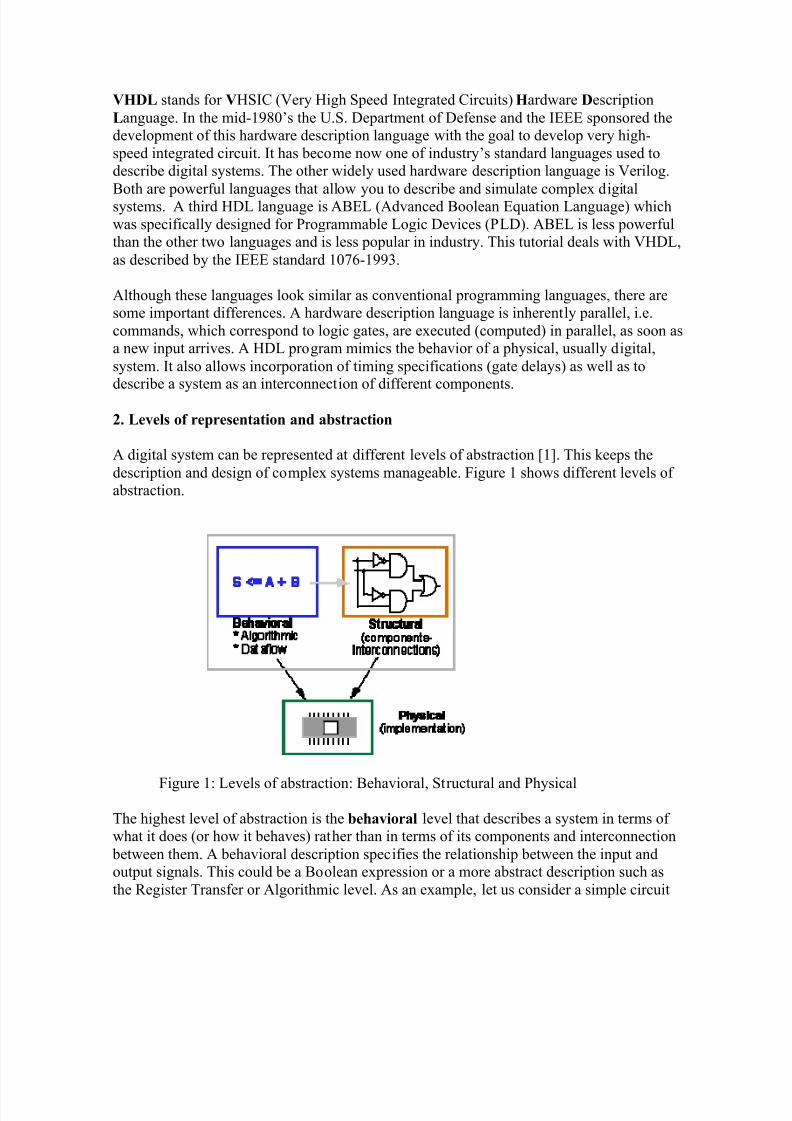
A digital system can be represented at different levels of abstraction [1]. This keeps thedescription and design of complex systems manageable. Figure 1 shows different levels of abstraction.
Figure 1: Levels of abstraction: Behavioral, Structural and Physical
The highest level of abstraction is the behavioral level that describes a system in terms of what it does (or how it behaves) rather than in terms of its components and interconnection between them. A behavioral description specifies the relationship between the input andoutput signals. This could be a Boolean expression or a more abstract description such asthe Register Transfer or Algorithmic level. As an example, let us consider a simple circuit
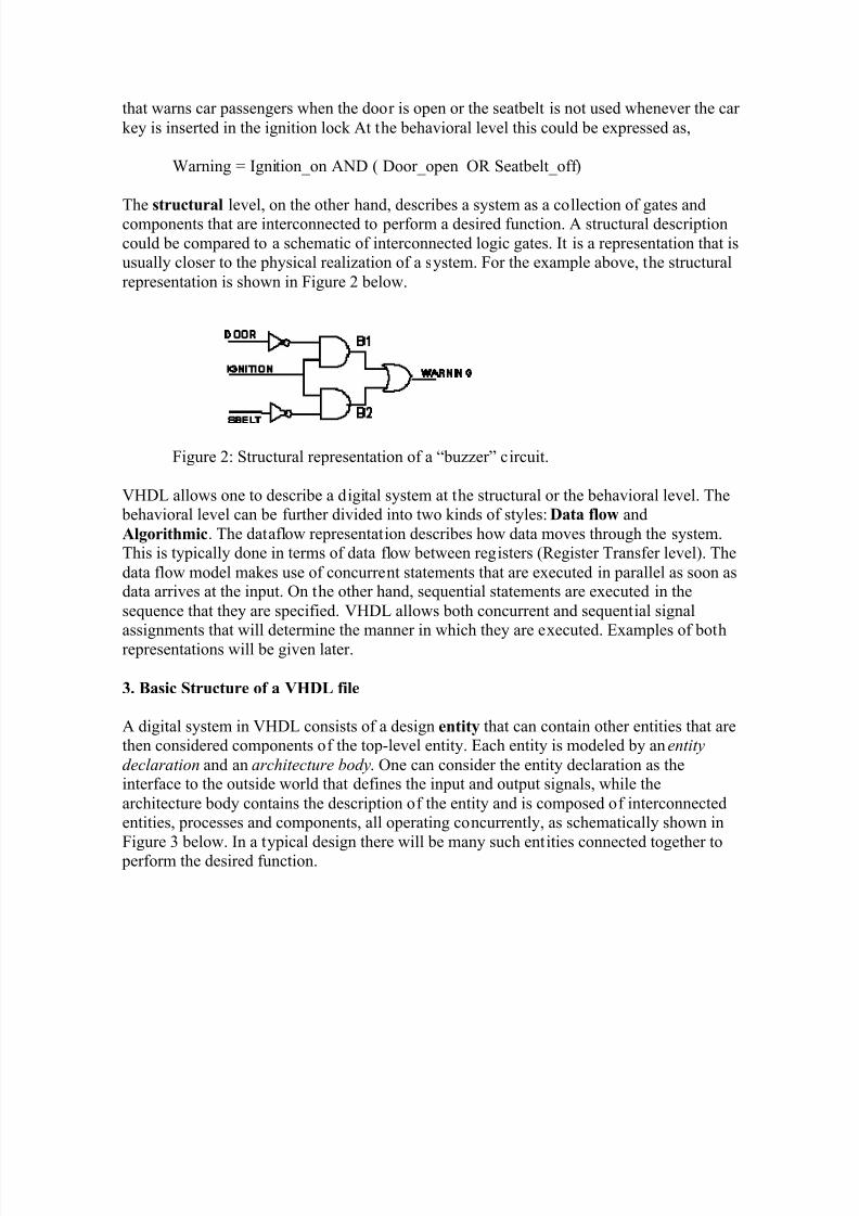
that warns car passengers when the door is open or the seatbelt is not used whenever the car key is inserted in the ignition lock At the behavioral level this could be expressed as,
Warning = Ignition_on AND ( Door_open OR Seatbelt_off)
The structural level, on the other hand, describes a system as a collection of gates andcomponents that are interconnected to perform a desired function. A structural descriptioncould be compared to a schematic of interconnected logic gates. It is a representation that isusually closer to the physical realization of a system. For the example above, the structuralrepresentation is shown in Figure 2 below.
Figure 2: Structural representation of a ³buzzer´ circuit.
VHDL allows one to describe a digital system at the structural or the behavioral level. The behavioral level can be further divided into two kinds of styles: Data flow andAlgorithmic. The dataflow representation describes how data moves through the system.This is typically done in terms of data flow between registers (Register Transfer level). Thedata flow model makes use of concurrent statements that are executed in parallel as soon asdata arrives at the input. On the other hand, sequential statements are executed in thesequence that they are specified. VHDL allows both concurrent and sequential signalassignments that will determine the manner in which they are executed. Examples of bothrepresentations will be given later.
3. Basic Structure of a VHDL file
A digital system in VHDL consists of a design entity that can contain other entities that arethen considered components of the top-level entity. Each entity is modeled by an entity
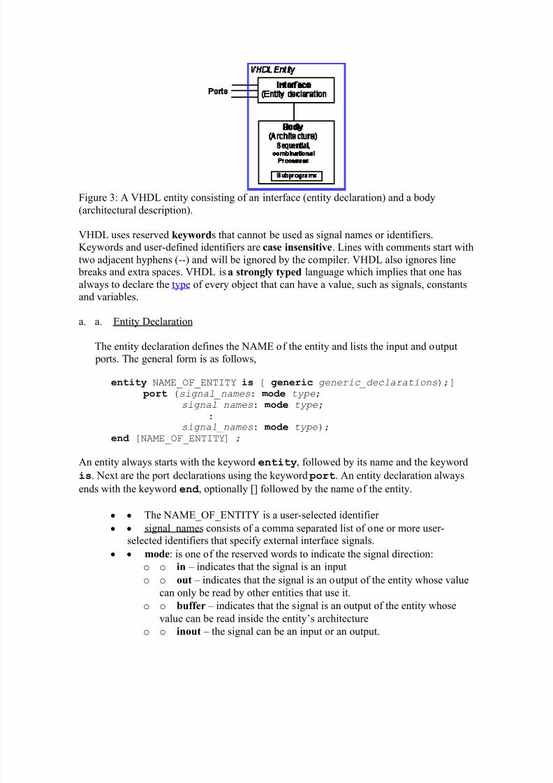
declaration and an architecture body. One can consider the entity declaration as theinterface to the outside world that defines the input and output signals, while thearchitecture body contains the description of the entity and is composed of interconnectedentities, processes and components, all operating concurrently, as schematically shown inFigure 3 below. In a typical design there will be many such entities connected together to perform the desired function.
Figure 3: A VHDL entity consisting of an interface (entity declaration) and a body(architectural description).
VHDL uses reserved keywords that cannot be used as signal names or identifiers.Keywords and user-defined identifiers are case insensitive. Lines with comments start withtwo adjacent hyphens (--) and will be ignored by the compiler. VHDL also ignores line
breaks and extra spaces. VHDL is a strongly typed language which implies that one hasalways to declare the type of every object that can have a value, such as signals, constantsand variables.
a. a. Entity Declaration
The entity declaration defines the NAME of the entity and lists the input and output ports. The general form is as follows,
entity NAME_OF_ENTITY is [ generic generic_declarations);] port (signal_names: m od e type;
signal_names: m od e type;
: signal_names: m od e type);
end [NAME_OF_ENTITY] ;
An entity always starts with the keyword entity, followed by its name and the keyword
is. Next are the port declarations using the keyword port. An entity declaration always
ends with the keyword end , optionally [] followed by the name of the entity.
y y The NAME_OF_ENTITY is a user-selected identifier
y y signal_names consists of a comma separated list of one or more user-selected identifiers that specify external interface signals.
y y mode: is one of the reserved words to indicate the signal direction:
o o in ± indicates that the signal is an input
o o out ± indicates that the signal is an output of the entity whose value
can only be read by other entities that use it.
o o buffer ± indicates that the signal is an output of the entity whose
value can be read inside the entity¶s architecture
o o inout ± the signal can be an input or an output.
y y type: a built-in or user-defined signal type. Examples of types are bit, bit_vector, Boolean, character, std_logic, and std_ulogic.
o o bit ± can have the value 0 and 1
o o bit_vector ± is a vector of bit values (e.g. bit_vector (0 to 7)
o o std_logic, std_ulogic, std_logic_vector, std_ulogic_vector : can have
9 values to indicate the value and strength of a signal. Std_ulogic andstd_logic are preferred over the bit or bit_vector types.
o o boolean ± can have the value TRUE and FALSE
o o integer ± can have a range of integer values
o o real ± can have a range of real values
o o character ± any printing character
o o time ± to indicate time
y y generic: generic declarations are optional and determine the local constantsused for timing and sizing (e.g. bus widths) the entity. A generic can have adefault value. The syntax for a generic follows,
generic (con stant_name: type [:=value] ;con stant_name: type [:=value] ;:con stant_name: type [:=value] );
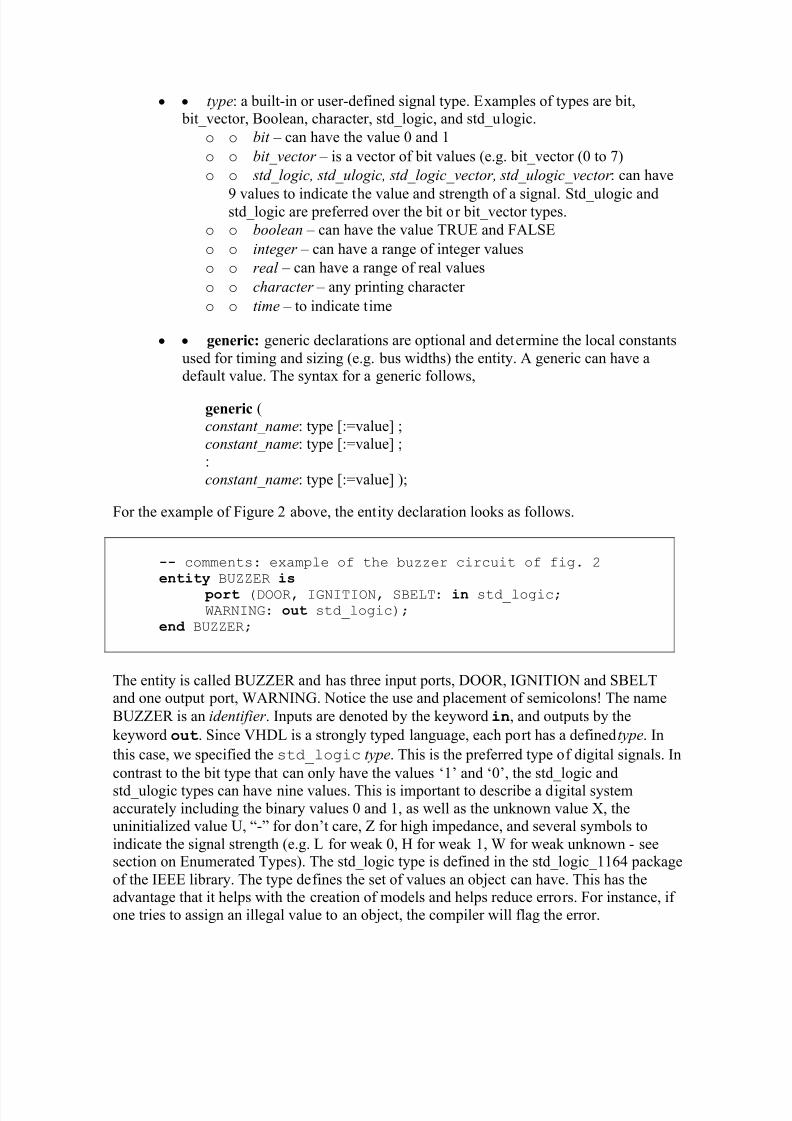
For the example of Figure 2 above, the entity declaration looks as follows.
-- comments: example of the buzzer circuit of fig. 2 entity BUZZER is
port (DOOR, IGNITION, SBELT: in std_logic; WARNING: out std_logic);
end BUZZER;
The entity is called BUZZER and has three input ports, DOOR, IGNITION and SBELTand one output port, WARNING. Notice the use and placement of semicolons! The name
BUZZER is an identifier . Inputs are denoted by the keyword in, and outputs by the
keyword out. Since VHDL is a strongly typed language, each port has a defined type. In
this case, we specified the std_logic type. This is the preferred type of digital signals. In
contrast to the bit type that can only have the values µ1¶ and µ0¶, the std_logic and
std_ulogic types can have nine values. This is important to describe a digital systemaccurately including the binary values 0 and 1, as well as the unknown value X, theuninitialized value U, ³-´ for don¶t care, Z for high impedance, and several symbols toindicate the signal strength (e.g. L for weak 0, H for weak 1, W for weak unknown - seesection on Enumerated Types). The std_logic type is defined in the std_logic_1164 packageof the IEEE library. The type defines the set of values an object can have. This has theadvantage that it helps with the creation of models and helps reduce errors. For instance, if one tries to assign an illegal value to an object, the compiler will flag the error.
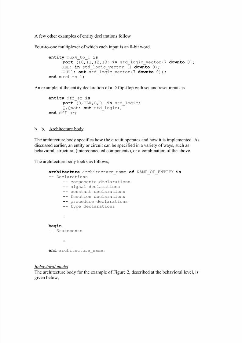
A few other examples of entity declarations follow
Four-to-one multiplexer of which each input is an 8-bit word.
entity mux4_to_1 is port (I0,I1,I2,I3: in std_logic_vector(7 downto 0); SEL: in std_logic_vector (1 downto 0); OUT1: out std_logic_vector(7 downto 0));
end mux4_to_1;
An example of the entity declaration of a D flip-flop with set and reset inputs is
entity dff_sr is port (D,CLK,S,R: in std_logic; Q,Qnot: out std_logic);
end dff_sr;
b. b. Architecture body
The architecture body specifies how the circuit operates and how it is implemented. Asdiscussed earlier, an entity or circuit can be specified in a variety of ways, such as behavioral, structural (interconnected components), or a combination of the above.
The architecture body looks as follows,
architecture architecture_name of NAME_OF_ENTITY is-- Declarations
-- components declarations -- signal declarations -- constant declarations -- function declarations -- procedure declarations -- type declarations
:
begin-- Statements
:
end architecture_name;
Behavioral model
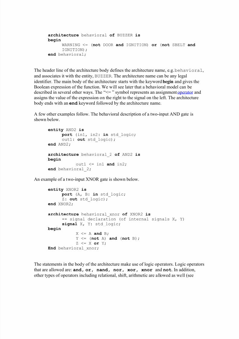
The architecture body for the example of Figure 2, described at the behavioral level, isgiven below,
WARNING <= (not DOOR and IGNITION) or (not SBELT and IGNITION);
end behavioral;
The header line of the architecture body defines the architecture name, e.g. behavioral,
and associates it with the entity, BUZZER. The architecture name can be any legal
identifier. The main body of the architecture starts with the keyword begin and gives theBoolean expression of the function. We will see later that a behavioral model can bedescribed in several other ways. The ³<= ´ symbol represents an assignment operator andassigns the value of the expression on the right to the signal on the left. The architecture body ends with an end keyword followed by the architecture name.
A few other examples follow. The behavioral description of a two-input AND gate is
shown below.
entity AND2 is port (in1, in2: in std_logic; out1: out std_logic);
end AND2;
architecture behavioral_2 of AND2 is begin
out1 <= in1 and in2; end behavioral_2;
An example of a two-input XNOR gate is shown below.
entity XNOR2 is port (A, B: in std_logic; Z: out std_logic);
end XNOR2;
architecture behavioral_xnor of XNOR2 is-- signal declaration (of internal signals X, Y)
signal X, Y: std_logic; begin
X <= A and B;
Y <= (not A) and (not B); Z <= X or Y;
End behavioral_xnor;
The statements in the body of the architecture make use of logic operators. Logic operators
that are allowed are: and, or, nand, nor, xor, xnor and not. In addition,
other types of operators including relational, shift, arithmetic are allowed as well (see
section on Operators). For more information on behavioral modeling see section onBehavioral Modeling.
C oncurrencyIt is worth pointing out that the signal assignments in the above examples are concurrent
statements. This implies that the statements are executed when one or more of the signalson the right hand side change their value (i.e. an event occurs on one of the signals). For instance, when the input A changes, the internal signals X and Y change values that in turncauses the last statement to update the output Z. There may be a propagation delayassociated with this change. Digital systems are basically data-driven and an event whichoccurs on one signal will lead to an event on another signal, etc. The execution of thestatements is determined by the flow of signal values. As a result, the order in which thesestatements are given does not matter (i.e., moving the statement for the output Z ahead of that for X and Y does not change the outcome). This is in contrast to conventional, software programs that execute the statements in a sequential or procedural manner.
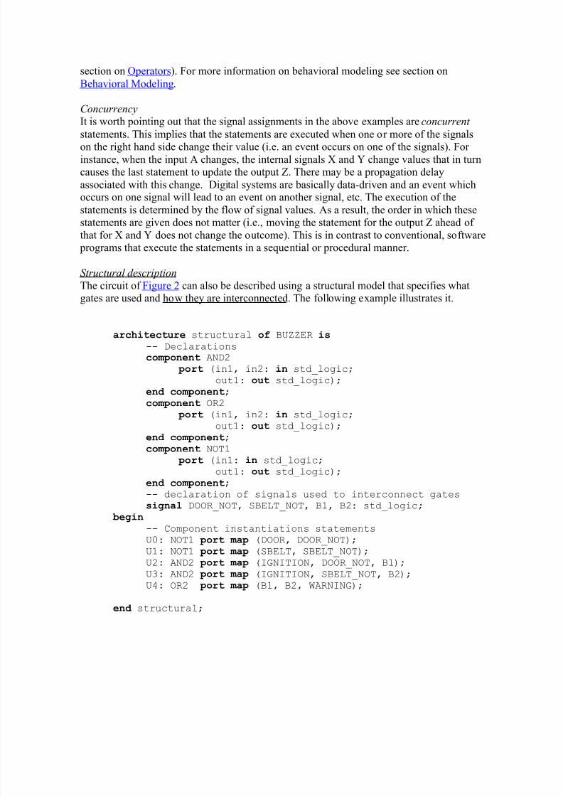
Structural de scription
The circuit of Figure 2 can also be described using a structural model that specifies whatgates are used and how they are interconnected. The following example illustrates it.
architecture structural of BUZZER is
-- Declarations co m ponent AND2
port (in1, in2: in std_logic; out1: out std_logic);
end co m ponent; co m ponent OR2
port (in1, in2: in std_logic; out1: out std_logic);
end co m ponent; co m ponent NOT1
port (in1: in std_logic; out1: out std_logic);
end co m ponent; -- declaration of signals used to interconnect gates signal DOOR_NOT, SBELT_NOT, B1, B2: std_logic;
begin-- Component instantiations statements U0: NOT1 port ma p (DOOR, DOOR_NOT); U1: NOT1 port ma p (SBELT, SBELT_NOT); U2: AND2 port ma p (IGNITION, DOOR_NOT, B1); U3: AND2 port ma p (IGNITION, SBELT_NOT, B2); U4: OR2 port ma p (B1, B2, WARNING);
Following the header is the declarative part that gives the components (gates) that aregoing to be used in the description of the circuits. In our example, we use a two- input ANDgate, two-input OR gate and an inverter. These gates have to be defined first, i.e. they willneed an entity declaration and architecture body (as shown in the previous example). Thesecan be stored in one of the package s one refers to in the header of the file (see Library and
Packages below). The declarations for the components give the inputs (e.g. in1, in2) and theoutput (e.g. out1). Next, one has to define internal nets (signal names). In our examplethese signals are called DOOR_NOT, SBELT_NOT, B1, B2 (see Figure 2). Notice that onealways has to declare the type of the signal.
The statement s after the begin keyword gives the instantiations of the components anddescribes how these are interconnected. A component instantiation statement creates a newlevel of hierarchy. Each line starts with an in stance name (e.g. U0) followed by a colon and
a component name and the keyword port ma p. This keyword defines how the
components are connected. In the example above, this is done through positionalassociation: DOOR corresponds to the input, in1 of the NOT1 gate and DOOR_NOT to the
output. Similarly, for the AND2 gate where the first two signals (IGNITION andDOOR_NOT) correspond to the inputs in1 and in2, respectively, and the signal B1 to theoutput out1. An alternative way is to use explicit association between the ports, as shown below.
U0: NOT1 port ma p (in1 => DOOR, out1 => DOOR_NOT); U1: NOT1 port ma p (in1 => SBELT, out1 => SBELT_NOT); U2: AND2 port ma p (in1 => IGNITION, in2 => DOOR_NOT, out1 => B1); U3: AND2 port ma p (in1 => IGNITION, in2 => SBELT_NOT, B2); U4: OR2 port ma p (in1 => B1, in2 => B2, out1 => WARNING);
Notice that the order in which these statements are written has no bearing on the executionsince these statements are concurrent and therefore executed in parallel. Indeed, theschematic that is described by these statements is the same independent of the order of thestatements.
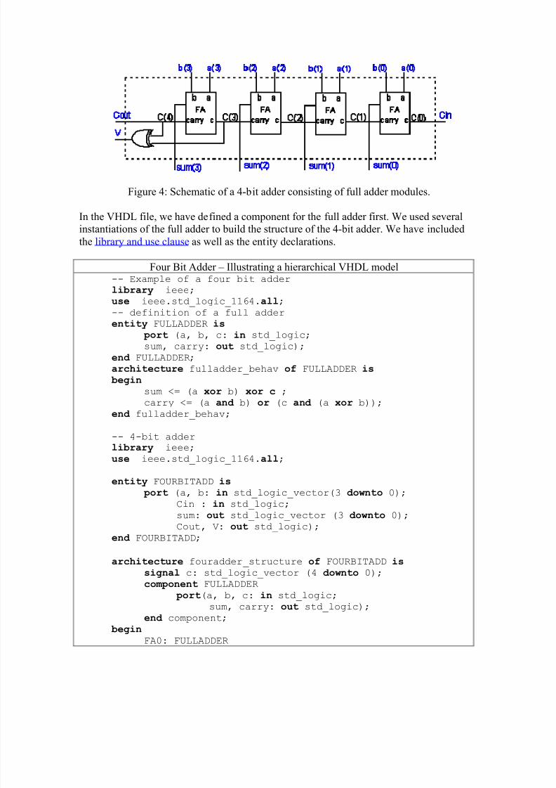
Structural modeling of design lends itself to hierarchical design, in which one can definecomponents of units that are used over and over again. Once these components are definedthey can be used as blocks, cells or macros in a higher level entity. This can significantlyreduce the complexity of large designs. Hierarchical design approaches are always preferred over flat designs. We will illustrate the use of a hierarchical design approach for a
4-bit adder, shown in Figure 4 below. Each full adder can be described by the Booleanexpressions for the sum and carry out signals,
Figure 4: Schematic of a 4-bit adder consisting of full adder modules.
In the VHDL file, we have defined a component for the full adder first. We used severalinstantiations of the full adder to build the structure of the 4-bit adder. We have includedthe library and use clause as well as the entity declarations.
Four Bit Adder ± Illustrating a hierarchical VHDL model-- Example of a four bit adder library ieee; use ieee.std_logic_1164.all;
-- definition of a full adder entity FULLADDER is
port (a, b, c: in std_logic; sum, carry: out std_logic);
end FULLADDER; architecture fulladder_behav of FULLADDER is begin
sum <= (a xor b) xor c ; carry <= (a and b) or (c and (a xor b));
end fulladder_behav;
-- 4-bit adder library ieee; use ieee.std_logic_1164.all;
entity FOURBITADD is port (a, b: in std_logic_vector(3 downto 0);
Cin : in std_logic; sum: out std_logic_vector (3 downto 0); Cout, V: out std_logic);
end FOURBITADD;
architecture fouradder_structure of FOURBITADD issignal c: std_logic_vector (4 downto 0);
co m ponent FULLADDER
port(a, b, c: in std_logic; sum, carry: out std_logic);
FA1: FULLADDER port ma p (a(1), b(1), C(1), sum(1), c(2));
FA2: FULLADDER port ma p (a(2), b(2), C(2), sum(2), c(3));
FA3: FULLADDER
port ma p (a(3), b(3), C(3), sum(3), c(4)); V <= c(3) xor c(4);
Cout <= c(4); end fouradder_structure;
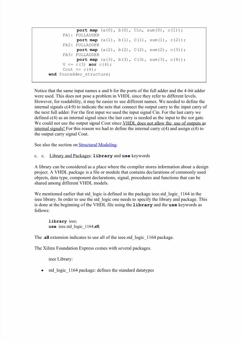
Notice that the same input names a and b for the ports of the full adder and the 4-bit adder were used. This does not pose a problem in VHDL since they refer to different levels.However, for readability, it may be easier to use different names. We needed to define theinternal signals c(4:0) to indicate the nets that connect the output carry to the input carry of the next full adder. For the first input we used the input signal Cin. For the last carry we
defined c(4) as an internal signal since the last carry is needed as the input to the xor gate.We could not use the output signal Cout since VHDL does not allow the use of outputs asinternal signals! For this reason we had to define the internal carry c(4) and assign c(4) tothe output carry signal Cout.
See also the section on Structural Modeling.
c. c. Library and Packages: library and use keywords
A library can be considered as a place where the compiler stores information about a design project. A VHDL package is a file or module that contains declarations of commonly used
objects, data type, component declarations, signal, procedures and functions that can beshared among different VHDL models.
We mentioned earlier that std_logic is defined in the package ieee.std_logic_1164 in theieee library. In order to use the std_logic one needs to specify the library and package. Thisis done at the beginning of the VHDL file using the library and the use keywords as
follows:
library ieee;
use ieee.std_logic_1164.all;
The .all extension indicates to use all of the ieee.std_logic_1164 package.
The Xilinx Foundation Express comes with several packages.
ieee Library:
y std_logic_1164 package: defines the standard datatypes
y std_logic_arith package: provides arithmetic, conversion and comparison functionsfor the signed, unsigned, integer, std_ulogic, std_logic and std_logic_vector types
y std_logic_unsigned
y std_logic_misc package: defines supplemental types, subtypes, constants andfunctions for the std_logic_1164 package.
To use any of these one must include the library and use clause:library ieee;use ieee.std_logic_1164.all;use ieee.std_logic_arith.all;use ieee.std_logic_unsigned.all;
In addition, the synopsis library has the attributes package:
library SYNOPSYS;use SYNOPSYS.attributes.all;
One can add other libraries and packages. The syntax to declare a package is as follows:
-- Package declaration package name_of_package is
package declarations end package name_of_package;
-- Package body declarations package bod y name_of_package is
package body declarations end package bod y name_of_package;
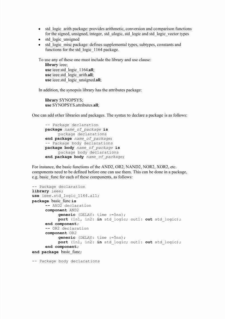
For instance, the basic functions of the AND2, OR2, NAND2, NOR2, XOR2, etc.components need to be defined before one can use them. This can be done in a package,e.g. basic_func for each of these components, as follows:
-- Package declaration library ieee; use ieee.std_logic_1164.all;
package basic_func is-- AND2 declaration co m ponent AND2
generic (DELAY: time :=5ns); port (in1, in2: in std_logic; out1: out std_logic);
end co m ponent;-- OR2 declaration co m ponent OR2
generic (DELAY: time :=5ns); port (in1, in2: in std_logic; out1: out std_logic);
package bod y basic_func is -- 2 input AND gate entity AND2 is
generic (DELAY: time);
port (in1, in2: in std_logic; out1: out std_logic); end AND2; architecture model_conc of AND2 is
beginout1 <= in1 and in2 after DELAY;
end model_conc;
-- 2 input OR gate entity OR2 is
generic (DELAY: time);
port (in1, in2: in std_logic; out1: out std_logic); end OR2; architecture model_conc2 of AND2 is
beginout1 <= in1 or in2 after DELAY;
end model_conc2;
end package bod y basic_func;
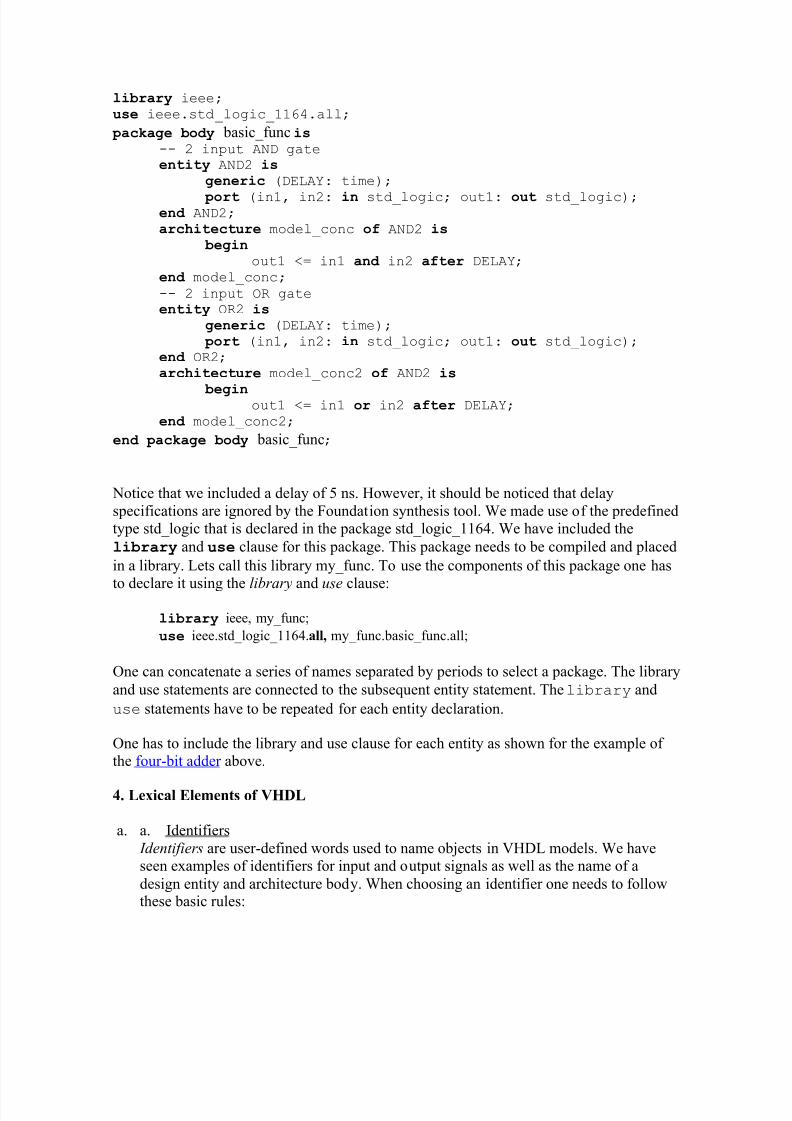
Notice that we included a delay of 5 ns. However, it should be noticed that delayspecifications are ignored by the Foundation synthesis tool. We made use of the predefinedtype std_logic that is declared in the package std_logic_1164. We have included the
library and use clause for this package. This package needs to be compiled and placed
in a library. Lets call this library my_func. To use the components of this package one has
to declare it using the library and u s
e clause:
library ieee, my_func;
use ieee.std_logic_1164.all, my_func.basic_func.all;
One can concatenate a series of names separated by periods to select a package. The library
and use statements are connected to the subsequent entity statement. The library and
use statements have to be repeated for each entity declaration.
One has to include the library and use clause for each entity as shown for the example of the four-bit adder above.
4. Lexical Elements of VHDL
a. a. Identifiers I dentifier s are user-defined words used to name objects in VHDL models. We haveseen examples of identifiers for input and output signals as well as the name of adesign entity and architecture body. When choosing an identifier one needs to followthese basic rules:
The above identifiers are called basic identifiers. The rules for these basic identifiers areoften too restrictive to indicate signals. For example, if one wants to indicate an active lowsignal such as an active low RESET, one cannot call it /RESET. In order to overcome theselimitations, there are a set of extended identifier rules which allow identifiers with any
sequence of characters.
y y An extended identifier is enclosed by the backslash, ³\´, character.
y y An extended identifier is case sensitive.
y y An extended identifier is different from reserved words (keywords) or any basic identifier (e.g. the identifier \identity\ is allowed)
y y Inside the two backslashes one can use any character in any order, except that a backslash as part of an extended identifier must be indicated by an additional backslash. As an example, to use the identifier BUS:\data, one writes:\BUS:\data\
y y Extended identifiers are allowed in the VHDL-93 version but not in VHDL-87
Some examples of legal identifiers are:
Input, \Input\, \input#1\, \Rst\\as\
b. b. Keywords (Reserved words)
Certain identifiers are used by the system as keywords for special use such as specificconstructs. These keywords cannot be used as identifiers for signals or objects we define.We have seen several of these reserved words already such as in, out, or, and, port, map,end, etc. Keywords are often printed in boldface, as is done in this tutorial. For a list of all
the keywords click on complete keyword list. Extended identifiers can make use of keywords since these are considered different words (e.g. the extended identifier \end\ isallowed.
c. c. Numbers
The default number representation is the decimal system. VHDL allows integer literals andreal literals. Integer literals consist of whole numbers without a decimal point, while real
literals always include a decimal point. Exponential notation is allowed using the letter ³E´or ³e´. For integer literals the exponent must always be positive. Examples are:
The number ±12 is a combination of a negation operator and an integer literal.
To express a number in a base different from the base ³10´, one uses the followingconvention: base#number#. A few examples follow.
Base 2: 2#10010# (representing the decimal number ³18´)Base 16: 16#12#Base 8: 8#22#
Base 2: 2#11101# (representing the decimal number ³29´)Base 16: 16#1D#Base 8: 8#35#
To make the readability of large numbers easier, one can insert underscores in the numbersas long as the underscore is not used at the beginning or the end.
2#1001_1101_1100_0010#215_123
d. d. Characters, Strings and Bit Strings
To use a character literal in a VHDL code, one puts it in a single quotation mark, as shownin the examples below:
µa¶, µB¶, µ,
On the other hand, a string of characters are placed in double quotation marks as shown inthe following examples:
³This is a string´,³To use a double quotation mark inside a string, use two double quotation marks´³This is a ³´String´´.´
Any printing character can be included inside a string.
A bit-string represents a sequence of bit values. In order to indicate that this is a bit string,one places the µB¶ in front of the string: B´1001´. One can also use strings in the hexagonalor octal base by using the X or O specifiers, respectively. Some examples are:
Notice that in the hexadecimal system, each digit represents exactly 4 bits. As a result, thenumber b´1001011´ is not the same as X´4b´ since the former has only 7 bits while thelatter represents a sequence 8 bits. For the same reason, O´113´ (represents 9 bits) is not
the same sequence as X´4b´ (represents 8 bits).
5. Data Objects: Signals, Variables and Constants
A data object is created by an object declaration and has a value and type associated withit. An object can be a Constant, Variable, Signal or a File. Up to now we have seen signalsthat were used as input or output ports or internal nets. Signals can be considered wires in aschematic that can have a current value and future values, and that are a function of thesignal assignment statements. On the other hand, Variables and Constants are used tomodel the behavior of a circuit and are used in processes, procedures and functions,similarly as they would be in a programming language. Following is a brief discussion of each class of objects.
C on stant
A constant can have a single value of a given type and cannot be changed during thesimulation. A constant is declared as follows,
constant list_of _name_of_constant: type [ := initial value] ;
where the initial value is optional. Constants can be declared at the start of an architectureand can then be used anywhere within the architecture. Constants declared within a processcan only be used inside that specific process.
constant RISE_FALL_TME: time := 2 ns; constant DELAY1: time := 4 ns;
constant RISE_TIME, FALL_TIME: time:= 1 ns;
constant DATA_BUS: integer:= 16;
V ariableA variable can have a single value, as with a constant, but a variable can be updated usinga variable assignment statement. The variable is updated without any delay as soon as thestatement is executed. Variables must be declared in side a process (and are local to the process). The variable declaration is as follows:
varia ble list_of_variable_names: type [ := initial value] ;
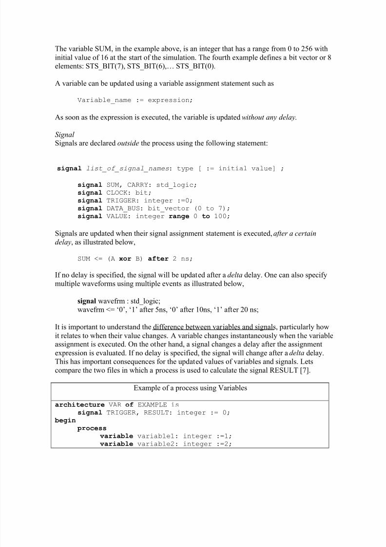
The variable SUM, in the example above, is an integer that has a range from 0 to 256 withinitial value of 16 at the start of the simulation. The fourth example defines a bit vector or 8elements: STS_BIT(7), STS_BIT(6),« STS_BIT(0).
A variable can be updated using a variable assignment statement such as
Variable_name := expression;
As soon as the expression is executed, the variable is updated without any delay.
Signal Signals are declared out side the process using the following statement:
signal list_of_signal_names: type [ := initial value] ;
signal SUM, CARRY: std_logic;
signal CLOCK: bit; signal TRIGGER: integer :=0; signal DATA_BUS: bit_vector (0 to 7);
signal VALUE: integer range 0 to 100;
Signals are updated when their signal assignment statement is executed, after a certain
delay, as illustrated below,
SUM <= (A xor B) after 2 ns;
If no delay is specified, the signal will be updated after a delta delay. One can also specify
multiple waveforms using multiple events as illustrated below,
signal wavefrm : std_logic;wavefrm <= µ0¶, µ1¶ after 5ns, µ0¶ after 10ns, µ1¶ after 20 ns;
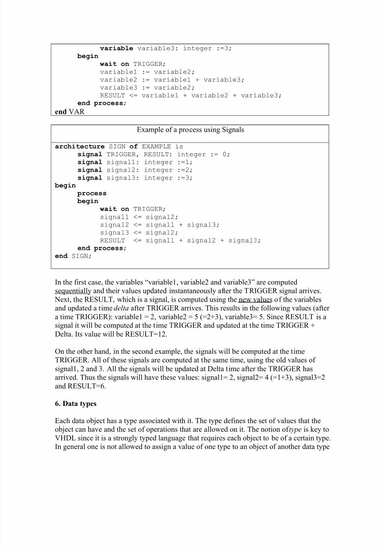
It is important to understand the difference between variables and signals, particularly howit relates to when their value changes. A variable changes instantaneously when the variableassignment is executed. On the other hand, a signal changes a delay after the assignmentexpression is evaluated. If no delay is specified, the signal will change after a delta delay.This has important consequences for the updated values of variables and signals. Letscompare the two files in which a process is used to calculate the signal RESULT [7].
In the first case, the variables ³variable1, variable2 and variable3´ are computedsequentially and their values updated instantaneously after the TRIGGER signal arrives. Next, the RESULT, which is a signal, is computed using the new values of the variablesand updated a time delta after TRIGGER arrives. This results in the following values (after a time TRIGGER): variable1 = 2, variable2 = 5 (=2+3), variable3= 5. Since RESULT is asignal it will be computed at the time TRIGGER and updated at the time TRIGGER +Delta. Its value will be RESULT=12.
On the other hand, in the second example, the signals will be computed at the timeTRIGGER. All of these signals are computed at the same time, using the old values of signal1, 2 and 3. All the signals will be updated at Delta time after the TRIGGER hasarrived. Thus the signals will have these values: signal1= 2, signal2= 4 (=1+3), signal3=2
and RESULT=6.
6. Data types
Each data object has a type associated with it. The type defines the set of values that theobject can have and the set of operations that are allowed on it. The notion of type is key toVHDL since it is a strongly typed language that requires each object to be of a certain type.In general one is not allowed to assign a value of one type to an object of another data type
(e.g. assigning an integer to a bit type is not allowed). There are four classes of data types:scalar, composite, access and file types. The scalar types represent a single value and areordered so that relational operations can be performed on them. The scalar type includesinteger, real, and enumerated types of Boolean and Character. Examples of these will begiven further on.
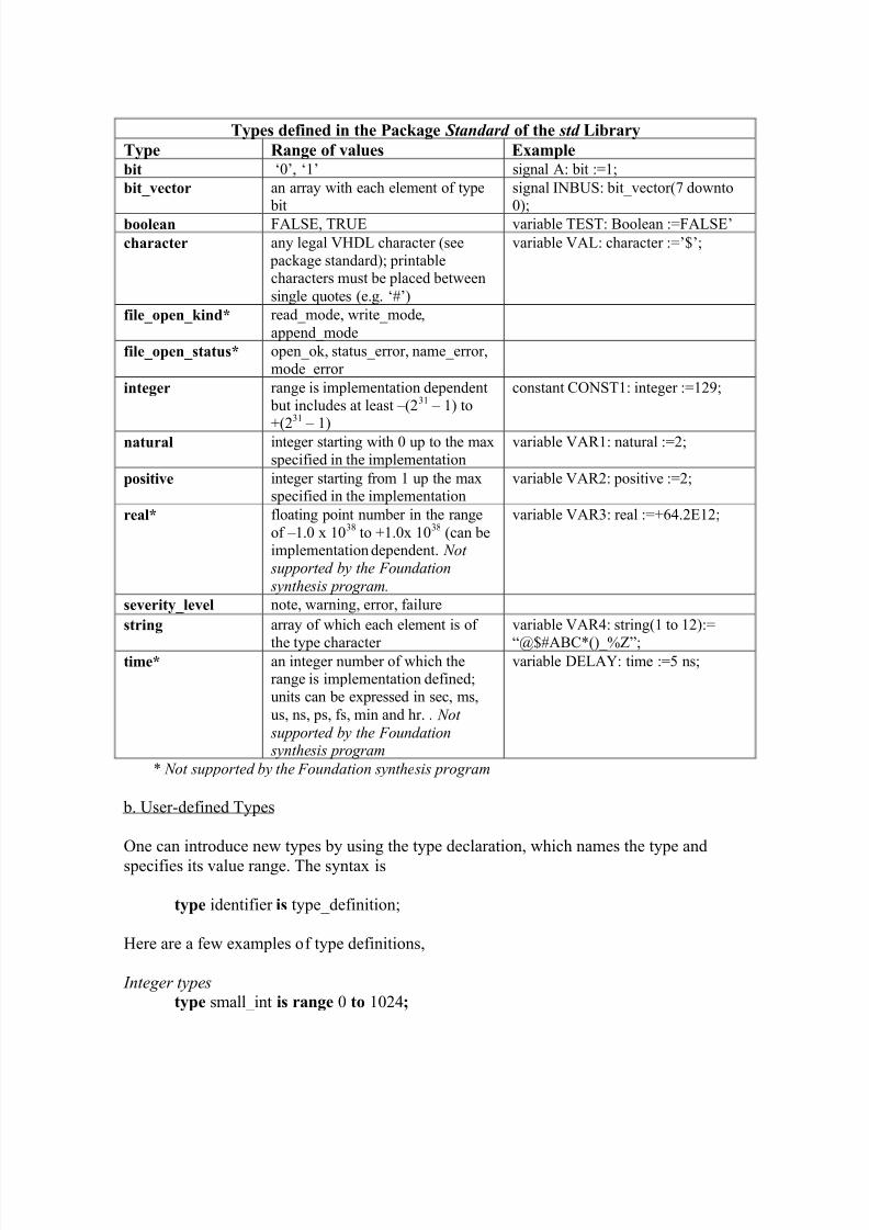
a. Data Types defined in the Standard Package
VHDL has several predefined types in the standard package as shown in the table below.To use this package one has to include the following clause:
subtype data_word is my_word_length range 7 downto 0;
A subtype is a subset of a previously defined type. The last example above illustrates theuse of subtypes. It defines a type called data_word that is a sybtype of my_word_length of
which the range is restricted from 7 to 0. Another example of a subtype is,
subtype int_small is integer range -1024 to +1024;
Floating-point type s
type cmos_level is range 0.0 to 3.3;type pmos_level is range -5.0 to 0.0;type probability is range 0.0 to 1.0;subtype cmos_low_V is cmos_level range 0.0 to +1.8;
Note that floating point data types are not supported by the Xilinx Foundation synthesis program.
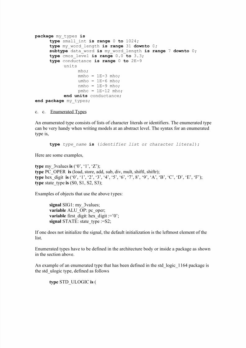
P hy sical type s
The physical type definition includes a units identifier as follows,
ty pe conductance is range 0 to 2E-9
units mho;
mmho = 1E-3 mho; umho = 1E-6 mho;
nmho = 1E-9 mho; pmho = 1E-12 mho;
end units conductance;
Here are some object declarations that use the above types,
variable BUS_WIDTH: small_int :=24;
signal DATA_BUS: my_word_length;variable VAR1: cmos_level range 0.0 to 2.5;constant LINE_COND: conductance:= 125 umho;
Notice that a space must be left before the unit name.
The physical data types are not supported by the Xilinx Foundation Express synthesis program.
In order to use our own types, we need either to include the type definition inside anarchitecture body or to declare the type in a package. The latter can be done as follows for a package called ³my_types´.
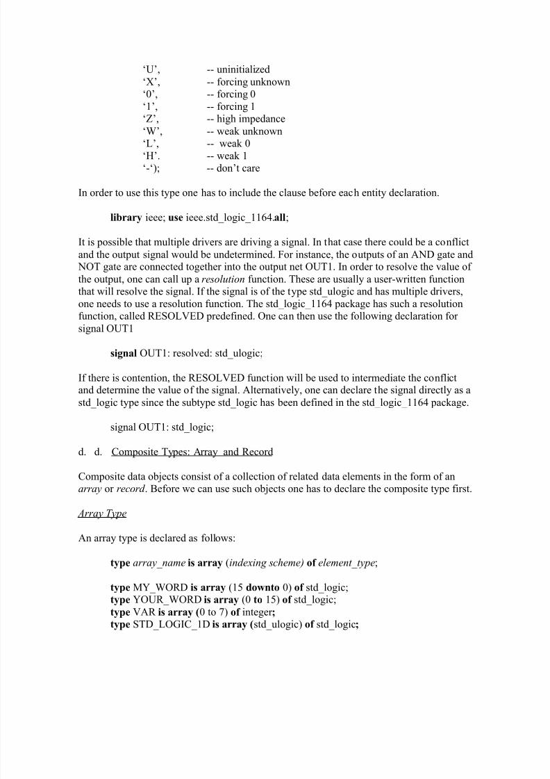
An enumerated type consists of lists of character literals or identifiers. The enumerated typecan be very handy when writing models at an abstract level. The syntax for an enumeratedtype is,
ty pe type_name is (identifier list or character literal);
Here are some examples,
type my_3values is (µ0¶, µ1¶, µZ¶);type PC_OPER is (load, store, add, sub, div, mult, shiftl, shiftr);type hex_digit is (µ0¶, µ1¶, µ2¶, µ3¶, µ4¶, µ5¶, µ6¶, µ7¶, 8¶, µ9¶, µA¶, µB¶, µC¶, µD¶, µE¶, µF¶);
In order to use this type one has to include the clause before each entity declaration.
library ieee; use ieee.std_logic_1164.all;
It is possible that multiple drivers are driving a signal. In that case there could be a conflictand the output signal would be undetermined. For instance, the outputs of an AND gate and NOT gate are connected together into the output net OUT1. In order to resolve the value of the output, one can call up a re solution function. These are usually a user-written functionthat will resolve the signal. If the signal is of the type std_ulogic and has multiple drivers,one needs to use a resolution function. The std_logic_1164 package has such a resolutionfunction, called RESOLVED predefined. One can then use the following declaration for signal OUT1
signal OUT1: resolved: std_ulogic;
If there is contention, the RESOLVED function will be used to intermediate the conflictand determine the value of the signal. Alternatively, one can declare the signal directly as astd_logic type since the subtype std_logic has been defined in the std_logic_1164 package.
signal OUT1: std_logic;
d. d. Composite Types: Array and Record
Composite data objects consist of a collection of related data elements in the form of anarray or record . Before we can use such objects one has to declare the composite type first.
Array Type
An array type is declared as follows:
type array_name is array (indexing scheme) of element_type;
type MY_WORD is array (15 downto 0) of std_logic;type YOUR_WORD is array (0 to 15) of std_logic;
type VAR is array (0 to 7) of integer ;type STD_LOGIC_1D is array (std_ulogic) of std_logic;
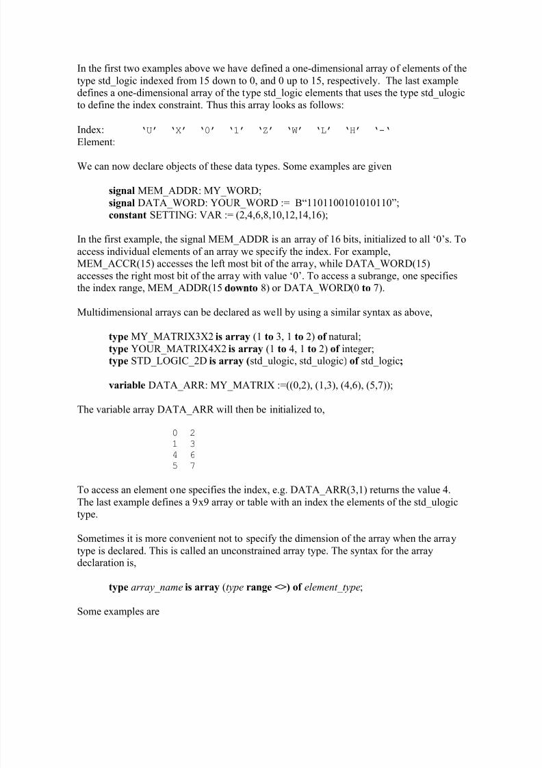
In the first two examples above we have defined a one-dimensional array of elements of thetype std_logic indexed from 15 down to 0, and 0 up to 15, respectively. The last exampledefines a one-dimensional array of the type std_logic elements that uses the type std_ulogicto define the index constraint. Thus this array looks as follows:
Index:µU
µX
µ0
µ1
µZ
µW
µL
µH
µ-µ Element:
We can now declare objects of these data types. Some examples are given
signal MEM_ADDR: MY_WORD;signal DATA_WORD: YOUR_WORD := B³1101100101010110´;constant SETTING: VAR := (2,4,6,8,10,12,14,16);
In the first example, the signal MEM_ADDR is an array of 16 bits, initialized to all µ0¶s. Toaccess individual elements of an array we specify the index. For example,
MEM_ACCR(15) accesses the left most bit of the array, while DATA_WORD(15)accesses the right most bit of the array with value µ0¶. To access a subrange, one specifiesthe index range, MEM_ADDR(15 downto 8) or DATA_WORD(0 to 7).
Multidimensional arrays can be declared as well by using a similar syntax as above,
type MY_MATRIX3X2 is array (1 to 3, 1 to 2) of natural;type YOUR_MATRIX4X2 is array (1 to 4, 1 to 2) of integer;type STD_LOGIC_2D is array (std_ulogic, std_ulogic) of std_logic;
The variable array DATA_ARR will then be initialized to,
0 21 34 65 7
To access an element one specifies the index, e.g. DATA_ARR(3,1) returns the value 4.The last example defines a 9x9 array or table with an index the elements of the std_ulogictype.
Sometimes it is more convenient not to specify the dimension of the array when the arraytype is declared. This is called an unconstrained array type. The syntax for the arraydeclaration is,
type array_name is array (type range <>) of element_type;
type MATRIX is array (integer range <>) of integer;type VECTOR_INT is array (natural range <>) of integer;type VECTOR2 is array (natural range <>, natural range <>) of std_logic;
The range is now specified when one declares the array object,
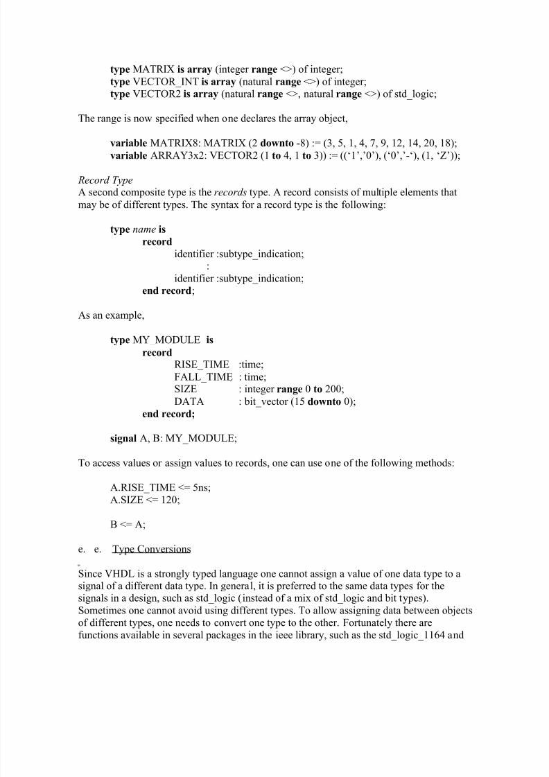
Record TypeA second composite type is the record s type. A record consists of multiple elements thatmay be of different types. The syntax for a record type is the following:
type name is record
identifier :subtype_indication;:
identifier :subtype_indication;end record;
As an example,
type MY_MODULE is
recordRISE_TIME :time;FALL_TIME : time;SIZE : integer range 0 to 200;DATA : bit_vector (15 downto 0);
end record;
signal A, B: MY_MODULE;
To access values or assign values to records, one can use one of the following methods:
A.RISE_TIME <= 5ns;A.SIZE <= 120;
B <= A;
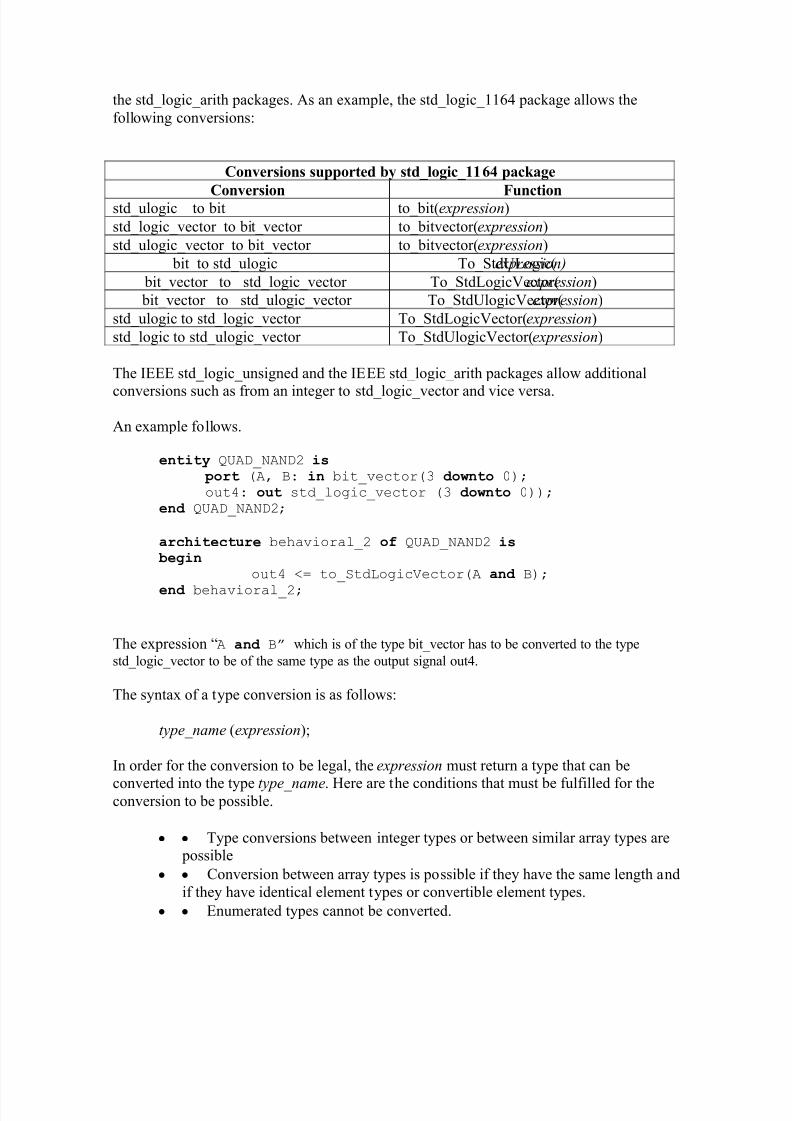
e. e. Type Conversions
Since VHDL is a strongly typed language one cannot assign a value of one data type to asignal of a different data type. In general, it is preferred to the same data types for thesignals in a design, such as std_logic (instead of a mix of std_logic and bit types).Sometimes one cannot avoid using different types. To allow assigning data between objectsof different types, one needs to convert one type to the other. Fortunately there arefunctions available in several packages in the ieee library, such as the std_logic_1164 and
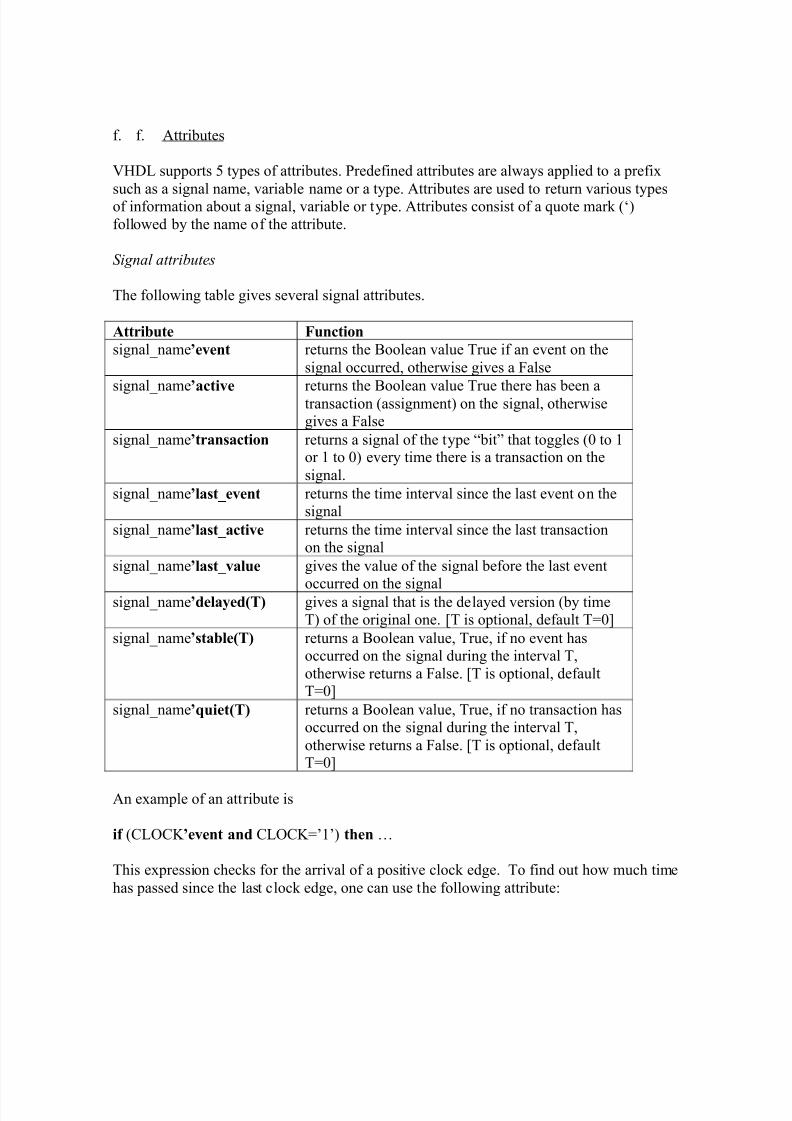
VHDL supports 5 types of attributes. Predefined attributes are always applied to a prefix
such as a signal name, variable name or a type. Attributes are used to return various typesof information about a signal, variable or type. Attributes consist of a quote mark (µ)followed by the name of the attribute.
Signal attribute s
The following table gives several signal attributes.
Attribute Function
signal_name¶event returns the Boolean value True if an event on thesignal occurred, otherwise gives a False
signal_name¶active returns the Boolean value True there has been atransaction (assignment) on the signal, otherwisegives a False
signal_name¶transaction returns a signal of the type ³bit´ that toggles (0 to 1or 1 to 0) every time there is a transaction on thesignal.
signal_name¶last_event returns the time interval since the last event on thesignal
signal_name¶last_active returns the time interval since the last transactionon the signal
signal_name¶last_value gives the value of the signal before the last event
occurred on the signalsignal_name¶delayed(T) gives a signal that is the delayed version (by timeT) of the original one. [T is optional, default T=0]
signal_name¶stable(T) returns a Boolean value, True, if no event hasoccurred on the signal during the interval T,otherwise returns a False. [T is optional, defaultT=0]
signal_name¶quiet(T) returns a Boolean value, True, if no transaction hasoccurred on the signal during the interval T,otherwise returns a False. [T is optional, defaultT=0]
An example of an attribute is
if (CLOCK ¶event and CLOCK=¶1¶) then «
This expression checks for the arrival of a positive clock edge. To find out how much timehas passed since the last clock edge, one can use the following attribute:
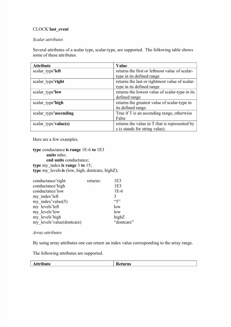
left-most element indexright-most indexupper boundlower boundthe number of elements
rangereverse rangea Boolean value TRUE if index is anascending range, otherwise FALSE
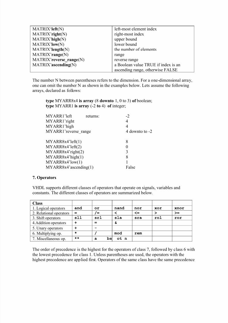
The number N between parentheses refers to the dimension. For a one-dimensional array,one can omit the number N as shown in the examples below. Lets assume the followingarrays, declared as follows:
type MYARR8x4 is array (8 downto 1, 0 to 3) of boolean;type MYARR1 is array (-2 to 4) of integer;
MYARR1¶left returns: -2MYARR1¶right 4MYARR1¶high 4MYARR1¶reverse_range 4 downto to -2
VHDL supports different classes of operators that operate on signals, variables andconstants. The different classes of operators are summarized below.
Class1. Logical operators and or nand nor xor xnor
2. Relational operators = /= < <= > >=
3. Shift operators sll srl sla sra rol ror
4.Addition operators + = &
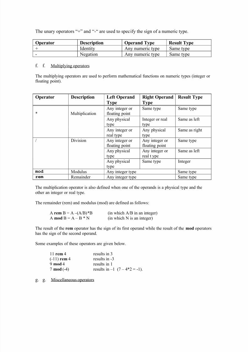
5. Unary operators + -
6. Multiplying op. * / m od re m
7. Miscellaneous op. ** a bs not
The order of precedence is the highest for the operators of class 7, followed by class 6 withthe lowest precedence for class 1. Unless parentheses are used, the operators with thehighest precedence are applied first. Operators of the same class have the same precedence
and are applied from left to right in an expression. As an example, consider the followingstd_ulogic_vectors, X (=¶010¶), Y(=¶10¶), and Z (µ10101¶). The expression
not X & Y xor Z rol 1
is equivalent to ((not X) & Y) xor (Z rol 1) = ((101) & 10) xor (01011) =(10110) xor(01011) = 11101. The xor is executed on a bit-per-bit basis.
a. a. Logic operators
The logic operators (and, or, nand, nor, xor and xnor) are defined for the ³bit´, ³boolean´,³std_logic´ and ³std_ulogic´ types and their vectors. They are used to define Boolean logicexpression or to perform bit-per-bit operations on arrays of bits. They give a result of thesame type as the operand (Bit or Boolean). These operators can be applied to signals,variables and constants.
Notice that the nand and nor operators are not associative. One should use parentheses in asequence of nand or nor operators to prevent a syntax error:
X nand Y nand Z will give a syntax error and should be written as (X nand Y) nand Z.
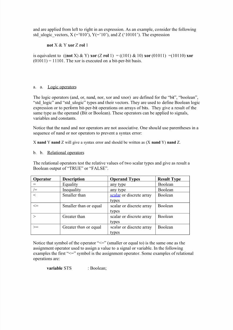
b. b. Relational operators
The relational operators test the relative values of two scalar types and give as result aBoolean output of ³TRUE´ or ³FALSE´.
Operator Description Operand Types Result Type
= Equality any type Boolean
/= Inequality any type Boolean
< Smaller than scalar or discrete arraytypes
Boolean
<= Smaller than or equal scalar or discrete arraytypes
Boolean
> Greater than scalar or discrete arraytypes
Boolean
>= Greater than or equal scalar or discrete array
types
Boolean
Notice that symbol of the operator ³<=´ (smaller or equal to) is the same one as theassignment operator used to assign a value to a signal or variable. In the followingexamples the first ³<=´ symbol is the assignment operator. Some examples of relationaloperations are:
constant A : integer :=24;constant B_COUNT : integer :=32;constant C : integer :=14;STS <= (A < B_COUNT) ; -- will assign the value ³TRUE´ to STSSTS <= ((A >= B_COUNT) or (A > C)); -- will result in ³TRUE´
variable A1: new_std_logic :=¶1¶;variable A2: new_std_logic :=¶Z¶;STS <= (A1 < A2); will result in ³TRUE´ since µ1¶ occurs to the left of µZ¶.
For discrete array types, the comparison is done on an element-per-element basis, startingfrom the left towards the right, as illustrated by the last two examples.
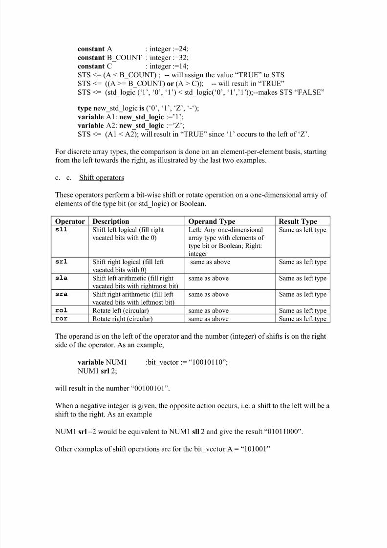
c. c. Shift operators
These operators perform a bit-wise shift or rotate operation on a one-dimensional array of elements of the type bit (or std_logic) or Boolean.
Operator Description Operand Type Result Typesll Shift left logical (fill right
vacated bits with the 0)Left: Any one-dimensionalarray type with elements of type bit or Boolean; Right:integer
Same as left type
srl Shift right logical (fill leftvacated bits with 0)
same as above Same as left type
sla Shift left arithmetic (fill right
vacated bits with rightmost bit)
same as above Same as left type
sra Shift right arithmetic (fill leftvacated bits with leftmost bit)
same as above Same as left type
rol Rotate left (circular) same as above Same as left typeror Rotate right (circular) same as above Same as left type
The operand is on the left of the operator and the number (integer) of shifts is on the rightside of the operator. As an example,
A sll 2 results in ³100100´A srl 2 results in ³001010´
A sla 2 results in ³100111´A sra 2 results in ³111010´A rol 2 results in ³100110´A ror 2 results in ³011010´
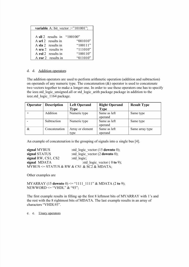
d. d. Addition operators
The addition operators are used to perform arithmetic operation (addition and subtraction)on operands of any numeric type. The concatenation (&) operator is used to concatenatetwo vectors together to make a longer one. In order to use these operators one has to specify
the ieee.std_logic_unsigned.all or std_logic_arith package package in addition to theieee.std_logic_1164 package.
Operator Description Left Operand
Type
Right Operand
Type
Result Type
+ Addition Numeric type Same as leftoperand
Same type
- Subtraction Numeric type Same as leftoperand
Same type
& Concatenation Array or elementtype
Same as leftoperand
Same array type
An example of concatenation is the grouping of signals into a single bus [4].
signal MYBUS :std_logic_vector (15 downto 0);signal STATUS :std_logic_vector (2 downto 0);signal RW, CS1, CS2 :std_logic;signal MDATA :std_logic_vector ( 0 to 9);MYBUS <= STATUS & RW & CS1 & SC2 & MDATA;
The first example results in filling up the first 8 leftmost bits of MYARRAY with 1¶s andthe rest with the 8 rightmost bits of MDATA. The last example results in an array of characters ³VHDL93´.
These are the absolute value and exponentation operators that can be applied to numerictypes. The logical negation (not) results in the inverse polarity but the same type.
Operator Description Left Operand
Type
Right Operand
Type
Result Type
** Exponentiation Integer type Integer type Same as left
Floating point Integer type Same as lefta bs Absolute value Any numeric type Same typenot Logical negation Any bit or Boolean type Same type
Delays or timing informationPackages (list standard, 1164 packages).
8. Behavioral Modeling: Sequential Statements
As discussed earlier, VHDL provides means to represent digital circuits at different levelsof representation of abstraction, such as the behavioral and structural modeling. In thissection we will discuss different constructs for describing the behavior of components andcircuits in terms of sequential statements. The basis for sequential modeling is the proce ss construct. As you will see, the proce ss construct allows us to model complex digitalsystems, in particular sequential circuits.
a. Process
A process statement is the main construct in behavioral modeling that allows you to usesequential statements to describe the behavior of a system over time. The syntax for a process statement is
[ proce ss _label :] process [ ( sen sitivity_li st ) ] [is][ proce ss _declaration s]
begin li st of sequential statement s such a s:
signal a ssignment s
variable a ssignment s ca se statement
exit statement if statement
loop statement next statement
null statement procedure call
wait statement end process [ proce ss _label ];
An example of a positive edge-triggered D flip-flop with asynchronous clear input follows.
port (CLK, CLEAR, D : in std_logic; Q : out std_logic);
end DFF_CLEAR;
architecture BEHAV_DFF of DFF_CLEAR is begin DFF_PROCESS: process (CLK, CLEAR)
beginif (CLEAR = µ1¶) then
Q <= µ0¶; elsif (CLK¶event and CLK = µ1¶) then
Q <= D; end if;
end process;end BEHAV_DFF;
A process is declared within an architecture and is a concurrent statement. However, thestatements inside a process are executed sequentially. Like other concurrent statements, a process reads and writes signals and values of the interface (input and output) ports tocommunicate with the rest of the architecture. One can thus make assignments to signalsthat are defined externally (e.g. interface ports) to the process, such as the Q output of the
flip-flop in the above example. The expression CLK¶event and CLK = µ1¶ checks for
a positive clock edge (clock event AND clock high).
The sensitivity list is a set of signals to which the process is sensitive. Any change in thevalue of the signals in the sensitivity list will cause immediate execution of the process. If the sensitivity list is not specified, one has to include a wait statement to make sure that the
process will halt. Notice that one cannot include both a sensitivity list and a wait statement.Variables and constants that are used inside a process have to be defined in the proce ss _declaration s part before the keyword begin. The keyword begin signals the startof the computational part of the process. The statements are sequentially executed,similarly as a conventional software program. It should be noted that variable assignmentsinside a process are executed immediately and denoted by the ³:=´ operator. This is incontrast to signal assignments denoted by ³<=´ and which changes occur after a delay. As aresult, changes made to variables will be available immediately to all subsequent statementswithin the same process. For an example that illustrates the difference between signal andvariable assignments see the section on Data Types (difference between signals andvariables).
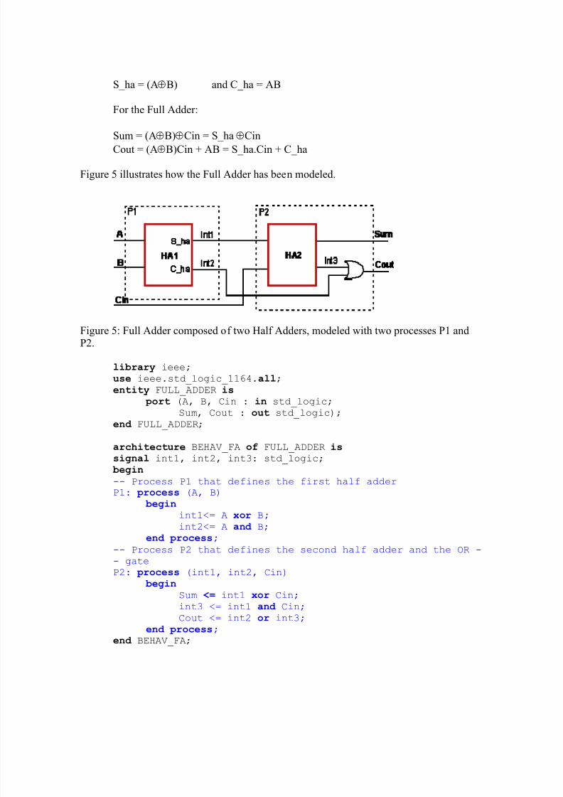
The previous example of the D flip-flop illustrates how to describe a sequential circuit withthe process statement. Although the process is mainly used to describe sequential circuits,one can also describe combinational circuits with the process construct. The followingexample illustrates this for a Full Adder, composed of two Half Adders. This example alsoillustrates how one process can generate signals that will trigger other processes whenevents on the signals in its sensitivity list occur [3]. We can write the Boolean expression of a Half Adder and Full Adder as follows:
Of course, one could simplify the behavioral model significantly by using a single process.
b. If Statements
Theif
statement executes a sequence of statements whose sequence depends on one or moreconditions. The syntax is as follows:
if condition then
sequential statements [elsif condition then
sequential statements ] [else
sequential statements ] end if;
Each condition is a Boolean expression. The if statement is performed by checking each
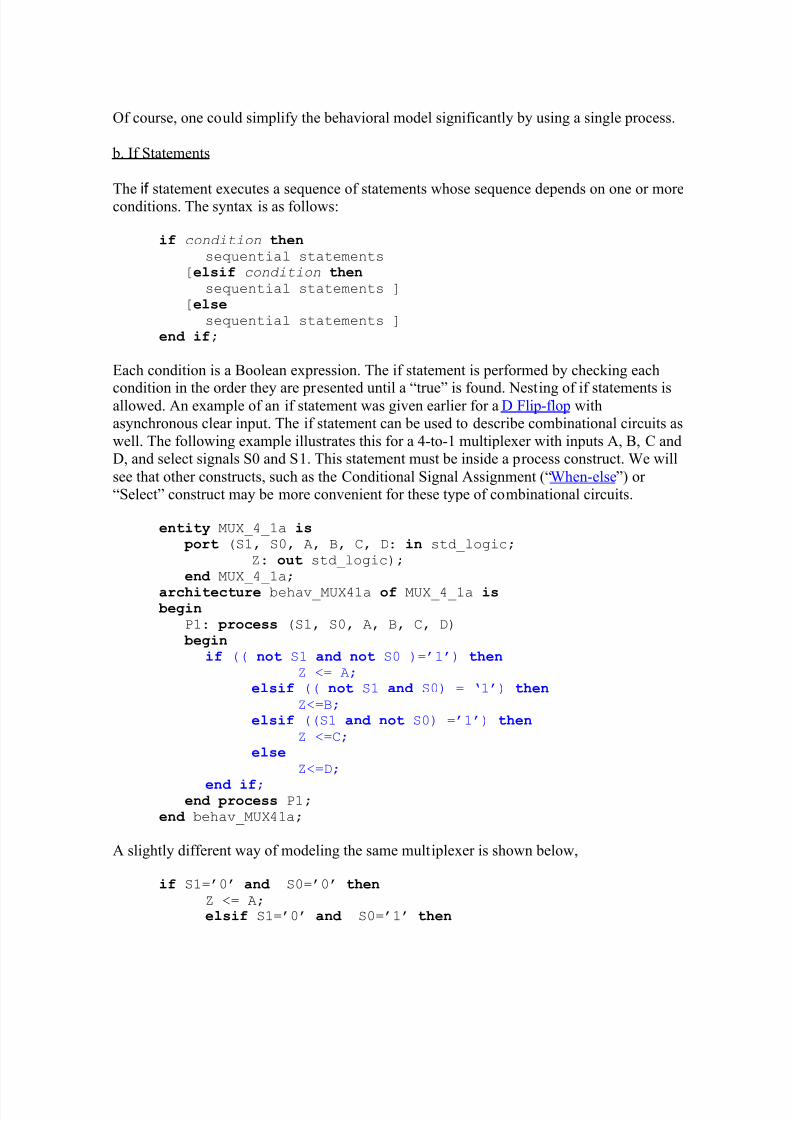
condition in the order they are presented until a ³true´ is found. Nesting of if statements isallowed. An example of an if statement was given earlier for a D Flip-flop withasynchronous clear input. The if statement can be used to describe combinational circuits aswell. The following example illustrates this for a 4-to-1 multiplexer with inputs A, B, C andD, and select signals S0 and S1. This statement must be inside a process construct. We willsee that other constructs, such as the Conditional Signal Assignment (³When-else´) or ³Select´ construct may be more convenient for these type of combinational circuits.
entity MUX_4_1a is port (S1, S0, A, B, C, D: in std_logic;
Z: out std_logic); end MUX_4_1a;
architecture behav_MUX41a of MUX_4_1a is begin
P1: process (S1, S0, A, B, C, D)
begin if (( not S1 and not S0 )=¶1¶) then
Z <= A; elsif (( not S1 and S0) = µ1¶) then
Z<=B; elsif ((S1 and not S0) =¶1¶) then
Z <=C; else
Z<=D;
end if; end process P1;
end behav_MUX41a;
A slightly different way of modeling the same multiplexer is shown below,
If statements are often used to implement state diagrams. For an example of a Mealymachine see Example Mealy Machine later on.
c. c. Case statements
The case statement executes one of several sequences of statements, based on the value of asingle expression. The syntax is as follows,
case expression is when choices =>
sequential statements when choices =>
sequential statements-- branches are allowed
[ when others => sequential statements ] end case;
The expression must evaluate to an integer, an enumerated type of a one-dimensional array,such as a bit_vector. The case statement evaluates the expression and compares the value toeach of the choices. The when clause corresponding to the matching choice will have itsstatements executed. The following rules must be adhered to:
y no two choices can overlap (i.e. each choice can be covered only once)y if the ³when others" choice is not present, all possible values of the expression must
be covered by the set of choices.
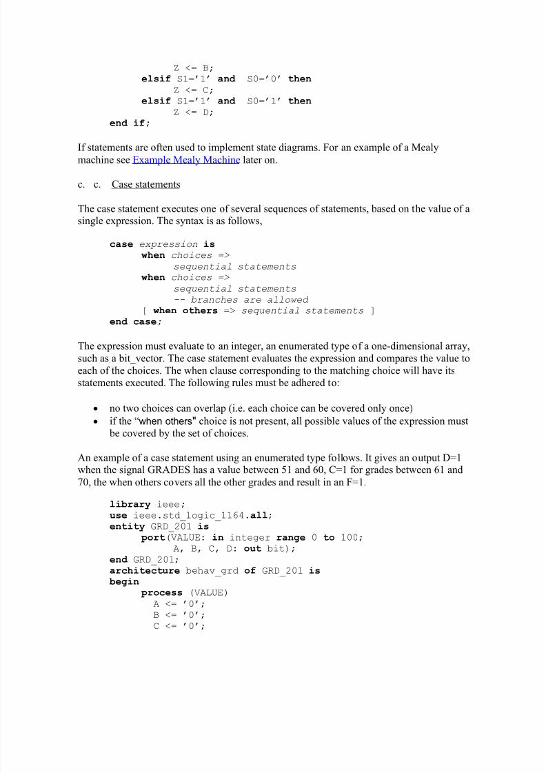
An example of a case statement using an enumerated type follows. It gives an output D=1when the signal GRADES has a value between 51 and 60, C=1 for grades between 61 and70, the when others covers all the other grades and result in an F=1.
library ieee;use ieee.std_logic_1164.all;
entity GRD_201 is
port(VALUE: in integer ra
nge 0 to 100; A, B, C, D: out bit);
end GRD_201; architecture behav_grd of GRD_201 is begin
We used the vertical bar ( | ) which is equivalent to the ³or´ operator, to illustrate how toexpress a range of values. This is a useful operator to indicate ranges that are not adjacent(e.g. 0 to 4 | 6 to 10).
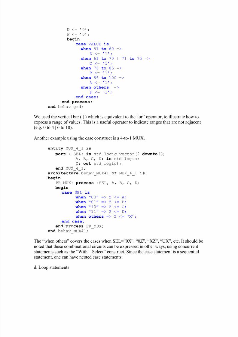
Another example using the case construct is a 4-to-1 MUX.
entity MUX_4_1 is
port ( SEL: in std_logic_vector(2 downto 1);A, B, C, D: in std_logic; Z: out std_logic);
end MUX_4_1; architecture behav_MUX41 of MUX_4_1 is
begin PR_MUX: process (SEL, A, B, C, D)
begin case SEL is
when ³00´ => Z <= A; when ³01´ => Z <= B;
when ³10´ => Z <= C;
when ³11´ => Z <= D;
when others => Z <= µX¶;
end case;end process PR_MUX;
end behav_MUX41;
The ³when others´ covers the cases when SEL=´0X´, ³0Z´, ³XZ´, ³UX´, etc. It should benoted that these combinational circuits can be expressed in other ways, using concurrentstatements such as the ³With ± Select´ construct. Since the case statement is a sequentialstatement, one can have nested case statements.
A loop statement is used to repeatedly execute a sequence of sequential statements. Thesyntax for a loop is as follows:
[ loop_label :]iteration_scheme loop
sequential statements[next [label] [ when condition];
[exit [label] [ when condition]; end loop [loop_label];
Labels are optional but are useful when writing nested loops. The next and exit statementare sequential statements that can only be used inside a loop.
y The next statement terminates the rest of the current loop iteration and executionwill proceed to the next loop iteration.
y The exit statement skips the rest of the statements, terminating the loop entirely, andcontinues with the next statement after the exited loop.
There are three types of iteration schemes:
y y basic loop
y y while « loop
y y for « loop
Ba sic Loop statement
This loop has no iteration scheme. It will be executed continuously until it encounters anexit or next statement.
[ loop_label :] loop
sequential statements[next [label] [ when condition]; [exit [label] [ when condition];
end loop [ loop_label];
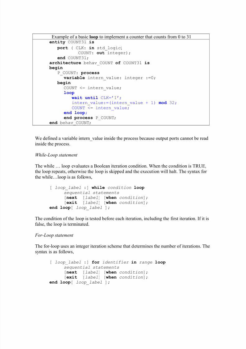
The basic loop (as well as the while-loop) must have at least one wait statement. As anexample, lets consider a 5-bit counter that counts from 0 to 31. When it reaches 31, it willstart over from 0. A wait statement has been included so that the loop will execute everytime the clock changes from µ0¶ to µ1¶.
Example of a basic loop to implement a counter that counts from 0 to 31entity COUNT31 is
port ( CLK: in std_logic;COUNT: out integer);
end COUNT31; architecture behav_COUNT of COUNT31 is begin
P_COUNT: process varia ble intern_value: integer :=0;
begin
COUNT <= intern_value; loop
wait until CLK=¶1¶; intern_value:=(intern_value + 1) m od 32;
COUNT <= intern_value; end loop; end process P_COUNT;
end behav_COUNT;
We defined a variable intern_value inside the process because output ports cannot be readinside the process.
W hile-Loop statement
The while « loop evaluates a Boolean iteration condition. When the condition is TRUE,the loop repeats, otherwise the loop is skipped and the execution will halt. The syntax for the while«loop is as follows,
[ loop_label :] while condition loop
sequential statements[next [label] [ when condition]; [exit [label] [ when condition];
end loop[ loop_label ];
The condition of the loop is tested before each iteration, including the first iteration. If it isfalse, the loop is terminated.
For-Loop statement
The for-loop uses an integer iteration scheme that determines the number of iterations. Thesyntax is as follows,
[ loop_label :] for identifier in range loop
sequential statements[next [label] [ when condition]; [exit [label] [ when condition];
y The identifier (index) is automatically declared by the loop itself, so one does notneed to declare it separately. The value of the identifier can only be read inside theloop and is not available outside its loop. One cannot assign or change the value of the index. This is in contrast to the while-loop whose condition can involve
variables that are modified inside the loop.y The range must be a computable integer range in one of the following forms, in
which integer_expression must evaluate to an integer:o integer_expre ssion to integer_expre ssion o integer_expre ssion downto integer_expre ssion
e. e. Next and Exit Statement
The next statement skips execution to the next iteration of a loop statement and proceedswith the next iteration. The syntax is
next [label] [ when condition];
The when keyword is optional and will execute the next statement when its conditionevaluates to the Boolean value TRUE.
The exit statement skips the rest of the statements, terminating the loop entirely, andcontinues with the next statement after the exited loop. The syntax is as follows:
exit [label] [ when condition];
The when keyword is optional and will execute the next statement when its conditionevaluates to the Boolean value TRUE.
Notice that the difference between the next and exit statement, is that the exit statementterminates the loop.
f. f. Wait statement
The wait statement will halt a process until an event occurs. There are several forms of thewait statement,
wait until condition;
wait for time expre ssion;
wait on signal;wait;
The Xilinx Foundation Express has implemented only the first form of the wait statement.The syntax is as follows,
wait until signal = value; wait until signal¶event and signal = value;
The condition in the ³ wait until´ statement must be TRUE for the process to resume. A
few examples follow.
wait until CLK=¶1¶; wait until CLK=¶0¶; wait until CLK¶event and CLK=¶1¶; wait until not CLK¶stable and CLK=¶1¶;
For the first example the process will wait until a positive-going clock edge occurs, whilefor the second example, the process will wait until a negative-going clock edge arrives. Thelast two examples are equivalent to the first one (positive-edge or 0-1 transitions). Thehardware implementation for these three statements will be identical.
It should be noted that a process that contains a wait statement can not have a sensitivitylist. If a process uses one or more wait statements, the Foundation Express synthesizer will
use sequential logic. The results of the computations are stored in flip-flops.
g. g. Null statement
The null statement states that no action will occur. The syntax is as follows,
null;
It can be useful in a case statement where all choices must be covered, even if some of them can be ignored. As an example, consider a control signal CNTL in the range 0 to 31.When the value of CNTL is 3 or 15, the signals A and B will be xor-ed, otherwise nothing
will occur.
entity EX_WAIT is
port ( CNTL: in integer range 0 to 31;A, B: in std_logic_vector(7 downto 0); Z: out std_logic_vector(7 downto 0) );
end EX_WAIT; architecture arch_wait of EX_WAIT is begin
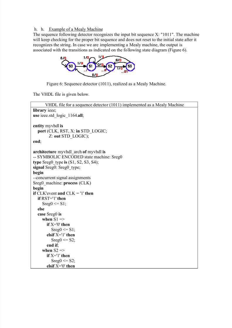
h. h. Example of a Mealy MachineThe sequence following detector recognizes the input bit sequence X: "1011". The machinewill keep checking for the proper bit sequence and does not reset to the initial state after itrecognizes the string. In case we are implementing a Mealy machine, the output isassociated with the transitions as indicated on the following state diagram (Figure 6).
Figure 6: Sequence detector (1011), realized as a Mealy Machine.
The VHDL file is given below.
VHDL file for a sequence detector (1011) implemented as a Mealy Machine
library ieee;
use ieee.std_logic_1164.all;
entity myvhdl is port (CLK, RST, X: in STD_LOGIC;
Z: out STD_LOGIC);
end;
architecture myvhdl_arch of myvhdl is -- SYMBOLIC ENCODED state machine: Sreg0type Sreg0_type is (S1, S2, S3, S4);signal Sreg0: Sreg0_type;
begin--concurrent signal assignmentsSreg0_machine: process (CLK)begin
end process;-- signal assignment statements for combinatorial outputsZ_assignment:Z <= '0' when (Sreg0 = S1 and X='0') else
'0' when (Sreg0 = S1 and X='1') else '0' when (Sreg0 = S2 and X='1') else '0' when (Sreg0 = S2 and X='0') else '0' when (Sreg0 = S3 and X='1') else '0' when (Sreg0 = S3 and X='0') else '0' when (Sreg0 = S4 and X='0') else '1' when (Sreg0 = S4 and X='1') else '1';
end myvhdl_arch;
9. Dataflow Modeling ± Concurrent Statements
Behavioral modeling can be done with sequential statements using the process construct or with concurrent statements. The first method was described in the previous section and isuseful to describe complex digital systems. In this section, we will use concurrent statements to describe behavior. This method is usually called dataflow modeling. Thedataflow modeling describes a circuit in terms of its function and the flow of data throughthe circuit. This is different from the structural modeling that describes a circuit in terms of the interconnection of components.
Concurrent signal assignments are event triggered and executed as soon as an event on oneof the signals occurs. In the remainder of the section we will describe several concurrentconstructs for use in dataflow modeling.
We have discussed several concurrent examples earlier in the tutorial. In this section wewill review the different types of concurrent signal assignments.
A simple concurrent signal assignment is given in the following examples,
Sum <= (A xor B) xor Cin; Carry <= (A and B); Z <= (not X) or Y after 2 ns;
The syntax is as follows:
Target_signal <= expression;
in which the value of the expression transferred to the target_signal. As soon as an event
occurs on one of the signals, the expression will be evaluated. The type of the target_signalhas to be the same as the type of the value of the expression.
Another example is given below of a 4-bit adder circuit. Notice that we specified the package: IEEE.std_logic_unsigned in order to be able to use the ³+´ (addition) operator.
Example of a Four bit Adder using concurrent/behavioral modelinglibrary ieee; use IEEE.std_logic_1164.all;
use IEEE.std_logic_unsigned.all;
entity ADD4 is port (
A: in STD_LOGIC_VECTOR (3 downto 0); B: in STD_LOGIC_VECTOR (3 downto 0);
CIN: in STD_LOGIC; SUM: out STD_LOGIC_VECTOR (3 downto 0);
COUT: out STD_LOGIC
); end ADD4;
architecture ADD4_concurnt of ADD4 is
-- define internal SUM signal including the carry signal SUMINT: STD_LOGIC_VECTOR(4 downto 0);
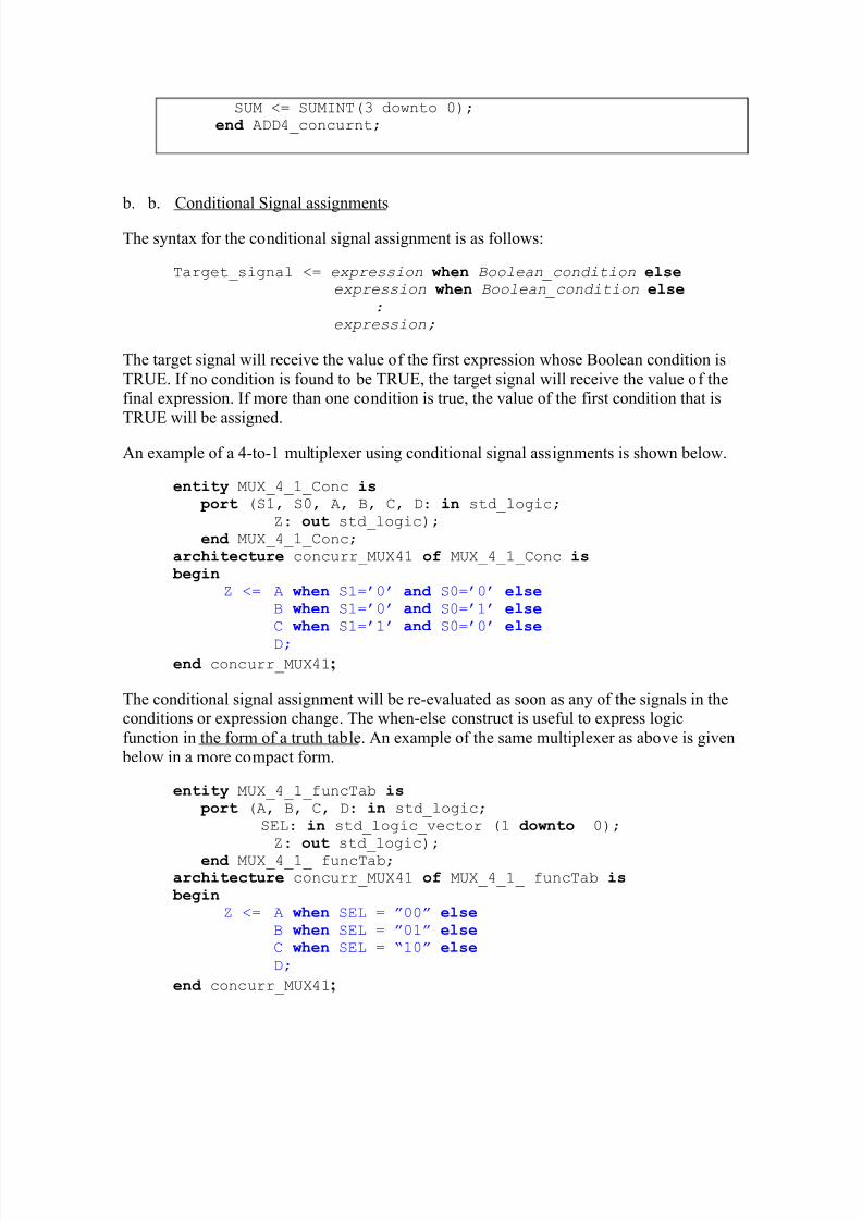
The syntax for the conditional signal assignment is as follows:
Target_signal <= expression when Boolean_condition elseexpression when Boolean_condition else
: expression;
The target signal will receive the value of the first expression whose Boolean condition isTRUE. If no condition is found to be TRUE, the target signal will receive the value of thefinal expression. If more than one condition is true, the value of the first condition that isTRUE will be assigned.
An example of a 4-to-1 multiplexer using conditional signal assignments is shown below.
entity MUX_4_1_Conc is port (S1, S0, A, B, C, D: in std_logic;
Z: out std_logic); end MUX_4_1_Conc;
architecture concurr_MUX41 of MUX_4_1_Conc is begin
Z <= A when S1=¶0¶ and S0=¶0¶ else B when S1=¶0¶ and S0=¶1¶ elseC when S1=¶1¶ and S0=¶0¶ else
D; end concurr_MUX41;
The conditional signal assignment will be re-evaluated as soon as any of the signals in theconditions or expression change. The when-else construct is useful to express logicfunction in the form of a truth table. An example of the same multiplexer as above is given below in a more compact form.
entity MUX_4_1_funcTab is port (A, B, C, D: in std_logic;
SEL: in std_logic_vector (1 downto 0); Z: out std_logic);
end MUX_4_1_ funcTab; architecture concurr_MUX41 of MUX_4_1_ funcTab is begin
Z <= A when SEL = ´00´ else B when SEL = ´01´ elseC when SEL = ³10´ else
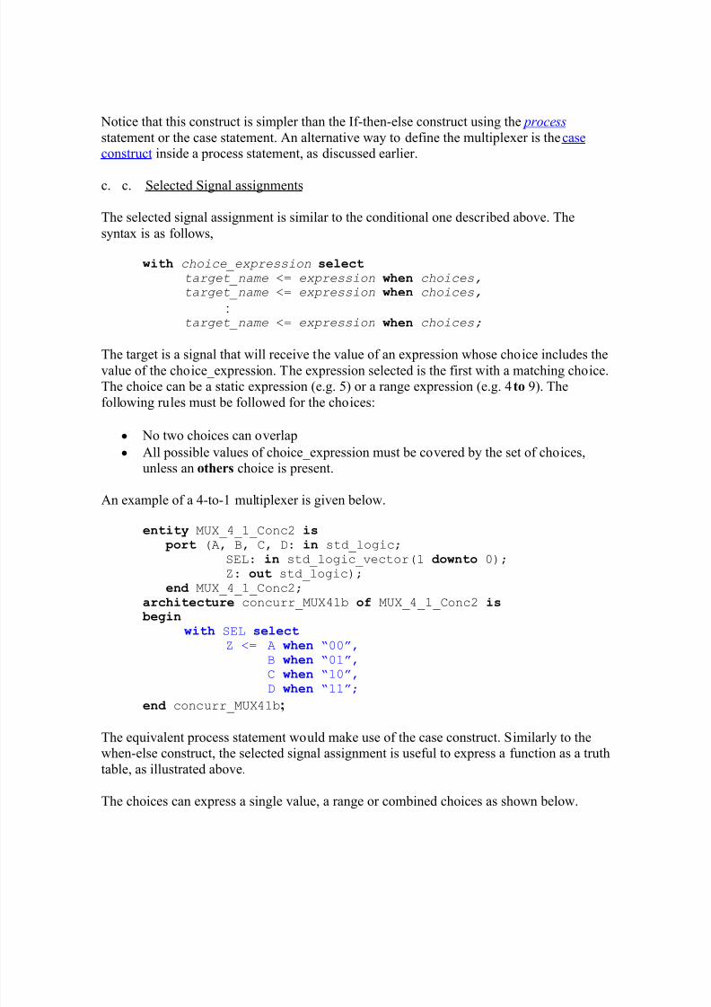
Notice that this construct is simpler than the If-then-else construct using the proce ss statement or the case statement. An alternative way to define the multiplexer is the caseconstruct inside a process statement, as discussed earlier.
c. c. Selected Signal assignments
The selected signal assignment is similar to the conditional one described above. Thesyntax is as follows,
with choice_expression selecttarget_name <= expression when choices,target_name <= expression when choices,
:target_name <= expression when choices;
The target is a signal that will receive the value of an expression whose choice includes thevalue of the choice_expression. The expression selected is the first with a matching choice.The choice can be a static expression (e.g. 5) or a range expression (e.g. 4 to 9). Thefollowing rules must be followed for the choices:
y No two choices can overlap
y All possible values of choice_expression must be covered by the set of choices,unless an others choice is present.
An example of a 4-to-1 multiplexer is given below.
entity MUX_4_1_Conc2 is port (A, B, C, D: in std_logic;
SEL: in std_logic_vector(1 downto 0); Z: out std_logic);
end MUX_4_1_Conc2; architecture concurr_MUX41b of MUX_4_1_Conc2 is begin
with SEL select Z <= A when ³00´,
B when ³01´, C when ³10´,D when ³11´;
end concurr_MUX41b;
The equivalent process statement would make use of the case construct. Similarly to thewhen-else construct, the selected signal assignment is useful to express a function as a truthtable, as illustrated above.
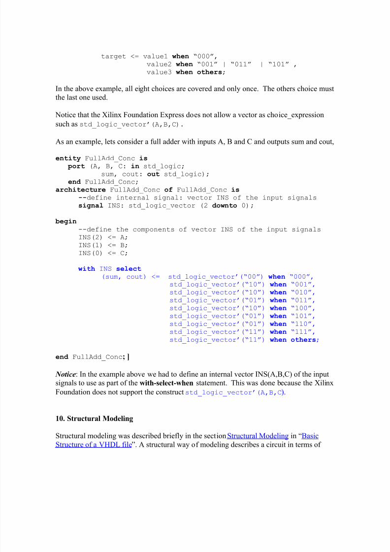
The choices can express a single value, a range or combined choices as shown below.
value2 when ³001´ | ³011´ | ³101´ ,value3 when others;
In the above example, all eight choices are covered and only once. The others choice must
the last one used.
Notice that the Xilinx Foundation Express does not allow a vector as choice_expression
such as std_logic_vector¶(A,B,C).
As an example, lets consider a full adder with inputs A, B and C and outputs sum and cout,
entity FullAdd_Conc is port (A, B, C: in std_logic;
sum, cout: out std_logic); end FullAdd_Conc;
architectureFullAdd_Conc
of
FullAdd_C
onc is
--define internal signal: vector INS of the input signals
signal INS: std_logic_vector (2 downto 0);
begin--define the components of vector INS of the input signals INS(2) <= A; INS(1) <= B; INS(0) <= C;
with INS select (sum, cout) <= std_logic_vector¶(³00´) when ³000´,
std_logic_vector¶(³10´) when ³001´,
std_logic_vector¶(³10´) when ³010´,std_logic_vector¶(³01´) when ³011´,
std_logic_vector¶(³10´) when ³100´,
std_logic_vector¶(³01´) when ³101´,
std_logic_vector¶(³01´) when ³110´,
std_logic_vector¶(³11´) when ³111´,
std_logic_vector¶(³11´) when others;
end FullAdd_Conc; ]
Notice: In the example above we had to define an internal vector INS(A,B,C) of the inputsignals to use as part of the
with-select-whenstatement. This was done because the Xilinx
Foundation does not support the construct std_logic_vector¶(A,B,C).
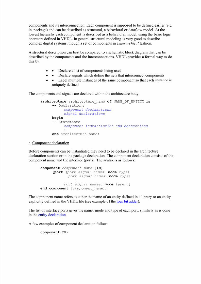
10. Structural Modeling
Structural modeling was described briefly in the section Structural Modeling in ³BasicStructure of a VHDL file´. A structural way of modeling describes a circuit in terms of
components and its interconnection. Each component is supposed to be defined earlier (e.g.in package) and can be described as structural, a behavioral or dataflow model. At thelowest hierarchy each component is described as a behavioral model, using the basic logicoperators defined in VHDL. In general structural modeling is very good to describecomplex digital systems, though a set of components in a hierarchical fashion.
A structural description can best be compared to a schematic block diagram that can bedescribed by the components and the interconnections. VHDL provides a formal way to dothis by
y y Declare a list of components being used
y y Declare signals which define the nets that interconnect components
y y Label multiple instances of the same component so that each instance isuniquely defined.
The components and signals are declared within the architecture body,
architecture architecture_name of NAME_OF_ENTITY is-- Declarations
component declarationssignal declarations
begin-- Statements
component instantiation and connections:
end architecture_name;
a. Component declaration
Before components can be instantiated they need to be declared in the architecturedeclaration section or in the package declaration. The component declaration consists of thecomponent name and the interface (ports). The syntax is as follows:
co m ponent component_name [is]
[ port ( port_signal_names: m od e type; port_signal_names: m od e type;
: port_signal_names: m od e type);]
end co m ponent [component_name];
The component name refers to either the name of an entity defined in a library or an entityexplicitly defined in the VHDL file (see example of the four bit adder ).
The list of interface ports gives the name, mode and type of each port, similarly as is donein the entity declaration.
port (in1, in2: in std_logic; out1: out std_logic);
end co m ponent;
co m ponent PROC port (CLK, RST, RW, STP: in std_logic;
ADDRBUS: out std_logic_vector (31 downto 0); DATA: inout integer range 0 to 1024);
co m ponent FULLADDER
port(a, b, c: in std_logic; sum, carry: out std_logic);
end component;
As mentioned earlier, the component declaration has to be done either in the architecture body or in the package declaration. If the component is declared in a package, one does not
have to declare it again in the architecture body as long as one uses the library and use
clause.
b. Component Instantiation and interconnections
The component instantiation statement references a component that can be
y Previously defined at the current level of the hierarchy or
y Defined in a technology library (vendor¶s library).
The syntax for the components instantiation is as follows,
in stance_name : component name
port map ( port1=> signal1, port2=> signal2,« port3=> signaln);
The instance name or label can be any legal identifier and is the name of this particular instance. The component name is the name of the component declared earlier using thecomponent declaration statement. The port name is the name of the port and signal is thename of the signal to which the specific port is connected. The above port map associatesthe ports to the signals through named association. An alternative method is the positionalassociation shown below,
port map ( signal1, signal2,« signaln);
in which the first port in the component declaration corresponds to the first signal, thesecond port to the second signal, etc. The signal position must be in the same order as thedeclared component¶s ports. One can mix named and positional associations as long as one puts all positional associations before the named ones. The following examples illustratesthis,
signal int1, int2, int3: std_logic;architecture struct of EXAMPLE is
U1: NAND2 port map (A,B,int1);U2: NAND2 port map (in2=>C, in2=>D, out1=>int2);U3: NAND3 port map (in1=>int1, int2, Z);«..
Another example is the Buzzer circuit of Figure 2.
11. References
1. D. Gajski and R. Khun, ³Introduction: New VLSI Tools,´ IEEE Computer, Vol. 16, No. 12, pp. 11-14, Dec. 1983.
2. M. Mano and C. Kime, ³Logic and Computer Design Fundamentals,´ 2nd Edition,
Prentice Hall, Upper Saddle River, 2001.3. S. Yalamanchili, ³VHDL Starter¶s Guide,´ Prentice Hall, Upper Saddle River,
1998.4. J. Bhasker, ³VHDL Primer,´ 3rd Edition, Prentice Hall, Upper Saddle River, 1998.5. P. J. Ashenden, ³The Student¶s Guide to VHDL,´ Morgan Kaufmann Publishers,
Inc, San Francisco, 1998.6. A. Dewey, ³Analysis and Design of Digital Systems,´ PWS Publishing Company,
New York, 1997.7. C. H. Roth, ³Digital System Design using VHDL´, PWS Publishing Company,
New York, 1998.8. D. Pellerin and D. Taylor, ³VHDL Made Easy!´, ,´ Prentice Hall, Upper Saddle
River, 1997.9. VHDL Reference Guide, Xilinx, Inc., 1999 (available on line:
http://toolbox.xilinx.com/docsan/ (select Foundation Series)
Copyright 2001; Created by Jan Van der Spiegel, Sept. 28, 2001; Updated August 6,2006Go to ESE201