0414/BSc/IT/TY/Pre_Pap/2014/IT_Soln 1 Vidyalankar T.Y. B.Sc. (IT) : Sem. VI Internet Technologies Prelim Question Paper Solution Comparison between OSI & TCP/IP When we compare the two models, we find that two layers, session and presentation, are missing from the TCP/IP protocol suite. These two layers were not added to the TCP/IP protocol suite after the publication of the OSI model. The application layer in the suite is usually considered to be the combination of three layers in the OSI model, as shown in Figure 1. Fig. 1 : TCP/IP and OSI model. Layers in the TCP/IP protocol suite Physical Layer TCP/IP does not define any specific protocol for the physical layer. It supports all of the standard and proprietary protocols. At this level, the communication is between two hops or nodes, either a computer or router. The unit of communication is a single bit. When the connection is established between the two nodes, a stream of bits is flowing between them. The physical layer, however, treats each bit individually. The unit of communication at the physical layer is a bit. Data Link Layer TCP/IP does not define any specific protocol for the data link layer either. It supports all of the standard and proprietary protocols. At this level, the communication is also between two hops or nodes. The unit of communication however, is a packet called a frame. A frame is a packet that encapsulates the data received from the network layer with an added header and sometimes a trailer. The head, among other communication information, includes the source and destination of frame. The destination address is needed to define the right recipient of the frame because many nodes may have been connected to the link. The unit of communication at the data link layer is a frame. 1. (a)
Transcript
0414/BSc/IT/TY/Pre_Pap/2014/IT_Soln 1
Vidyalankar T.Y. B.Sc. (IT) : Sem. VI
Internet Technologies Prelim Question Paper Solution
Comparison between OSI & TCP/IP When we compare the two models, we find that two layers, session and presentation, are missing from the TCP/IP protocol suite. These two layers were not added to the TCP/IP protocol suite after the publication of the OSI model. The application layer in the suite is usually considered to be the combination of three layers in the OSI model, as shown in Figure 1.
Fig. 1 : TCP/IP and OSI model. Layers in the TCP/IP protocol suite Physical Layer TCP/IP does not define any specific protocol for the physical layer. It supports all of the standard and proprietary protocols. At this level, the communication is between two hops or nodes, either a computer or router. The unit of communication is a single bit. When the connection is established between the two nodes, a stream of bits is flowing between them. The physical layer, however, treats each bit individually. The unit of communication at the physical layer is a bit. Data Link Layer TCP/IP does not define any specific protocol for the data link layer either. It supports all of the standard and proprietary protocols. At this level, the communication is also between two hops or nodes. The unit of communication however, is a packet called a frame. A frame is a packet that encapsulates the data received from the network layer with an added header and sometimes a trailer. The head, among other communication information, includes the source and destination of frame. The destination address is needed to define the right recipient of the frame because many nodes may have been connected to the link. The unit of communication at the data link layer is a frame.
1. (a)
Vidyalankar : T.Y. B.Sc. (IT) IT
0414/BSc/IT/TY/Pre_Pap/2014/IT_Soln 2
Network layer At the network layer (or, more accurately, the internetwork layer), TCP/IP supports the Internet Protocol (IP). The Internet Protocol (IP) is the transmission mechanism used by the TCP/IP protocols. IP transports data in packets called datagrams, each of which is transported separately. Datagrams can travel along different routes and can arrive out of sequence or be duplicated. IP does not keep track of the routes and has no facility for reordering datagrams once they arrive at their destination. The unit of communication at the network layer is a datagram. Transport Layer The network layer is responsible for sending individual datagrams from computer A to computer B; the transport layer is responsible for delivering the whole message, which is called a segment, a user datagram, or a packet, from A to B. A segment may consist of a few or tens of datagrams. The segments need to be broken into datagrams and each datagram has to be delivered to the network layer for transmission. Since the Internet defines a different route for each datagram, the datagrams may arrive out of order and may be lost. The transport layer at computer B needs to wait until all of these datagrams to arrive, assemble them and make a segment out of them. Traditionally, the transport layer was represented in the TCP/IP suite by two protocols: User Datagram Protocol (UDP) and Transmission Control Protocol (TCP). A new protocol called Stream Control Transmission Protocol (SCTP) has been introduced in the last few years. The unit of communication at the transport layer is a segment, user datagram, or a packet, depending on the specific protocol used in this layer. Application Layer The application layer in TCP/IP is equivalent to the combined session, presentation, and application layers in the OSI model. The application layer allows a user to access the services of our private internet or the global Internet. Many protocols are defined at this layer to provide services such as electronic mail, file transfer, accessing the World Wide Web, and so on. The unit of communication at the application layer is a message.
Fields related to Fragmentation The fields that are related to fragmentation and reassembly of an IP datagram are the identification, flags, and fragmentation offset fields. ● Identification. This 16-bit field identifies a datagram originating from the
source host. The combination of the identification and source IP address must uniquely define a datagram as it leaves the source host. To guarantee uniqueness, the IP protocol uses a counter to label the datagrams. The counter is initialized to a positive number. When the IP protocol sends a datagram, it copies the current value of the counter to the identification field and increments the counter by one. As long as the counter is kept in the main memory, uniqueness is guaranteed. When a datagram is fragmented, the value in the identification field is copied into all fragments. In other words, all fragments have the same identification number, which is also the same as
1. (b)
Prelim Question Paper Solution
0414/BSc/IT/TY/Pre_Pap/2014/IT_Soln 3
the original datagram. The identification number helps the destination in reassembling the datagram. It knows that all fragments having the same identification value should be assembled into one datagram.
● Flags. This is a three-bit field. The first bit is reserved (not used). The second
bit is called the do not fragment bit. If its value is 1, the machine must not fragment the datagram. If it cannot pass the datagram through any available physical network, it discards the datagram and sends an ICMP error message to the source host. If its value is 0, the datagram can be fragmented if necessary. The third bit is called the more fragment bit. If its value is 1, it means the datagram is not the last fragment; there are more fragments after this one. If its value is 0, it means this is the last or only fragment (see Figure 1).
Fig. 1 : Flags Field
● Fragmentation offset. This 13-bit field shows the relative position of this
fragment with respect to the whole datagram. It is the offset of the data in the original datagram measured in units of 8 bytes. Figure 2 shows a datagram with a data size of 4000 bytes fragmented into three fragments. The bytes in the original datagram are numbered 0 to 3999. The first fragment carries bytes 0 to 1399. The offset for this datagram is 0/8 = 0. The second fragment carries bytes 1400 to 2799; the offset value for this fragment is 1400/8 = 175. Finally, the third fragment carries bytes 2800 to 3999. The offset value for this fragment is 2800/8 = 350.
Fig. 2 : Fragmentation example
Remember that the value of the offset is measured in units of 8 bytes. This is
done because the length of the offset field is only 13 bits long and cannot represent a sequence of bytes greater than 8191. This forces hosts or routers that fragment datagrams to choose the size of each fragment so that the first byte number is divisible by 8.
Figure 3 shows an expanded view of the fragments in the previous figure.
Notice the value of the identification field is the same in all fragments. Notice the value of the flags field with the more bit set for all fragments except the last. Also, the value of the offset field for each fragment is shown.
Vidyalankar : T.Y. B.Sc. (IT) IT
0414/BSc/IT/TY/Pre_Pap/2014/IT_Soln 4
Fig. 3 : Detailed fragmentation example
The figure also shows what happens if a fragment itself is fragmented. In this
case the value of the offset field is always relative to the original datagram. For example, in the figure, the second fragment is itself fragmented later to two fragments of 800 bytes and 600 bytes, but the offset shows the relative position of the fragments to the original data.
It is obvious that even if each fragment follows a different path and arrives
out of order, the final destination host can reassemble the original datagram from the fragments received (if none of them is lost) using the following strategy: (a) The first fragment has an offset field value of zero. (b) Divide the length of the first fragment by 8. The second fragment has an
offset value equal to that result. (c) Divide the total length of the first and second fragment by 8. The third
fragment has an offset value equal to that result.
(d) Continue the process. The last fragment has a more bit value of 0.
Classful Addressing IP addresses, when started a few decades ago, used the concept of classes. This architecture is called classful addressing. In the mid-1990s, a new architecture, called classless addressing, was introduced that will eventually supersede the original architecture. However, most of the Internet is still using classful addressing and the migration is slow.
1. (c)
Fig. 1 : Occupation of the address space
Prelim Question Paper Solution
0414/BSc/IT/TY/Pre_Pap/2014/IT_Soln 5
In classful addressing, the IP address space is divided into five classes: A, B, C, D and E. Each class occupies some part of the whole address space. Figure 1 shows the class occupation of the address space (approximation). We can see from the figure that class A covers half of the address space, a serious design flaw. Class B covers 1/4 of the whole address space, another design flaw. Class C covers 1/8 of the address space, and classes D and E each cover 1/16 of the a space. Table 1 shows the number of addresses in each class.
Table 1 : Addresses per class
Class Number of Addresses Percentage
A 231 = 2,147,483,648 50%
B 230= 1,073,741,824 25%
229 = 536,870,912 12.5%
D 228 = 268,435,456 6.25%
E 228 = 268,435,456 6.25%
In classful addressing, the address space is divided into five classes: A, B, C, D, and E. IPV4 Packet Format
Fig. 1 : IP datagram
Input Module of ARP The input module waits until an ARP packet (request or reply) arrives. The input module checks the cache table to find an entry corresponding to this ARP packet. The target protocol address should match the protocol address of the entry. If the entry is found and the state of the entry is PENDING, the module updates the entry by copying the target hardware address in the packet to the hardware
1. (d)
2. (a)
Vidyalankar : T.Y. B.Sc. (IT) IT
0414/BSc/IT/TY/Pre_Pap/2014/IT_Soln 6
address field of the entry and changing the state to RESOLVED. The module also sets the value of the TIME-OUT for this entry. It then dequeues the packets from the corresponding queue, one by one, and delivers them along with the hardware address to the data link layer for transmission. If the entry is found and the state is RESOLVED, the module still updates the entry. This is because the target hardware address could have been changed. The value of the TIME-OUT field is also reset. If the entry is not found, the module creates a new entry and adds it to the table. The protocol requires that any information received is added to the table for future use. The state is set to RESOLVED and TIME-OUT is set. Now the module checks to see if the arrived ARP packet is a request. If it is, the module immediately creates an ARP reply message and sends it to the sender. The ARP reply packet is created by changing the value of the operation field from request to reply and filling in the target hardware address.
Input Module 1 Sleep until an ARP packet (request or reply) arrives.
. Check the cache table to find an entry corresponding to this ARP packet.
. If (found) 1. Update the entry. 2. If (the state is PENDING) 1. While the queue is not empty 1. Dequeue one packet. 2. Send the packet and the hardware address to data link. . If (not found)
1. Create an entry. 2. Add the entry to the table.5. If (the packet is a request) 1. Send an ARP reply.. Return.
Destination Unreachable & Source Quench Messages of ICMP a) Destination Unreachable
When a router cannot route a datagram or a host cannot deliver a datagram, the datagram is discarded and the router or the host sends a destination-unreachable message back to the source host that initiated the datagram.
Type 3 Code : 0 to 15 Checksum Unused (All 0s)
Part of the received IP datagram including IP header plus the first 8 bytes of datagram data
Fig. 1 : Destination-unreachable format
2. (b)
Prelim Question Paper Solution
0414/BSc/IT/TY/Pre_Pap/2014/IT_Soln 7
The code field for this type specifies the reason for discarding the datagram: 1) Code 0 : The network is unreachable, possibly due to hardware
failure. 2) Code 1 : The host is unreachable. This can also be due to hardware
failure. 3) Code 2 : The protocol is unreachable. 4) Code 3 : The port is unreachable. 5) Code 4 : Fragmentation is required, but the DF (do not fragment) field
of the datagram has been set. 6) Code 5 : Source routing cannot be accomplished. 7) Code 6 : The destination network is' unknown. 8) Code 7 : The destination host is unknown. 9) Code 8 : The source host is isolated. 10) Code 9 : Communication with the destination network is
administratively prohibited. 11) Code 10 : Communication with the destination host is administratively
prohibited. 12) Code 11 : The network is unreachable for the specified type of service. 13) Code 12 : The host is unreachable for the specified type of service. 14) Code 13 : The host is unreachable because the administrator has put a
filter on it. 15) Code 14 : The host is unreachable because the host precedence is
violated. 16) Code 15 : The host is unreachable because its precedence was cut off.
b) Source Quench The IP protocol is a connectionless protocol. There is no communication
between the source host, which produces the datagram, the routers, which forward it, and the destination host, which processes it. One of the ramifications of this absence of communication is the lack of flow control and congestion control.
There is no flow-control or congestion-control mechanism in the IP protocol.
The source-quench message in ICMP was designed to add a kind of flow control and congestion control to the IP. When a router or host discards a datagram due to congestion, it sends a source-quench message to the sender of the datagram. This message has two purposes. First, it informs the source that the datagram has been discarded. Second, it warns the source that there is congestion somewhere in the path and that the source should slow down (quench) the sending process. The source-quench format is shown in figure 2.
Type : 4 Code : 0 ChecksumUnused (All 0s)
Part of the received IP datagram including IP header plus the first 8 bytes of datagram data
Fig. 2 : Source-quench format
A source-quench message informs the source that a datagram has been discarded due to congestion in a router or the destination host. The source must slowdown the sending of datagrams until the congestion is relieved.
Vidyalankar : T.Y. B.Sc. (IT) IT
0414/BSc/IT/TY/Pre_Pap/2014/IT_Soln 8
Various phases of Mobile Agent To communicate with a remote host, a mobile host goes through three phases: agent discovery, registration, and data transfer, as shown in figure 1.
The first phase, agent discovery, involves the mobile host, the foreign agent, and the home agent. The second phase, registration, also involves the mobile host and the two agents. Finally, in the third phase, the remote host is also involved.
Fig. 1: Remote host and mobile host communication
Agent Discovery The first phase in mobile communication, agent discovery, consists of two sub phases. A mobile host must discover (learn the address of) a home agent before it leaves its home network. A mobile host must also discover a foreign agent after it has moved to a foreign network. This discovery consists of learning the care-of address as well as the foreign agent's address. The discovery involves two types of messages: advertisement and solicitation.
Agent Advertisement When a router advertises its presence on a network using an ICMP router advertisement, it can append an agent advertisement to the packet if it acts as an agent. Figure 2 shows how an agent advertisement is piggybacked to the router advertisement packet.
Mobile IP does not use a new packet type for agent advertisement; it uses the router advertisement packet of ICMP, and appends an agent advertisement message.
2. (c)
Prelim Question Paper Solution
0414/BSc/IT/TY/Pre_Pap/2014/IT_Soln 9
ICMPAdvertisement message
Type Length Sequence number Lifetime Code Reserved
Care-of addresses(foreign agent only)
Fig. 2 : Agent advertisement
The field descriptions are as follows: 1) Type : The 8-bit type field is set to 16. 2) Length : The 8-bit length field defines the total length of the extension
message (not the length of the ICMP advertisement message). 3) Sequence number : The 16-bit sequence number field holds the message
number. The recipient can use the sequence number to determine if a message is lost.
4) Lifetime : The lifetime field defines the number of seconds that the agent will accept requests. If the value is a string of 1 s, the lifetime is infinite.
5) Code : The code field is an 8-bit flag in which each bit is set (1) or unset (0). The meanings of the bits are shown in Table 1.
Table 1 : Code Bits
Bit Meaning0 Registration required. No colocated care-of address.1 Agent is busy and does not accept registration at this moment. 2 Agent acts as a home agent.3 Agent acts as a foreign agent.4 Agent uses minimal encapsulation.5 Agent uses generic routing encapsulation (GRE).6 Agent supports header compression.7 Unused (0).
6) Care-of Addresses : This field contains a list of addresses available for use
as care-of addresses. The mobile host can choose one of these addresses. The selection of this care-of address is announced in the registration request. Note that this field is used only by a foreign agent.
Agent Solicitation When a mobile host has moved to a new network and has not received agent advertisements, it can initiate an agent solicitation. It can use the ICMP solicitation message to inform an agent that it needs assistance. Mobile IP does not use a new packet type for agent solicitation; it uses the router solicitation packet of ICMP. Registration The second phase in mobile communication is registration. After a mobile host has moved to a foreign network and discovered the foreign agent, it must register. There are four aspects of registration:
Vidyalankar : T.Y. B.Sc. (IT) IT
0414/BSc/IT/TY/Pre_Pap/2014/IT_Soln 10
1) The mobile host must register itself with the foreign agent. 2) The mobile host must register itself with its home agent. This is normally
done by the foreign agent on behalf of the mobile host. 3) The mobile host must renew registration if it has expired. 4) The mobile host must cancel its registration (deregistration) when it returns
home. Request and Reply To register with the foreign agent and the home agent, the mobile host uses a registration request and a registration reply as shown in Figure 3. Registration Request A registration request is sent from the mobile host to the foreign agent to register its care-of address and also to announce its home address and home agent address. The foreign agent, after receiving and registering the request, relays the message to the home agent. Note that the home agent now knows the address of the foreign agent because the IP packet that is used for relaying has the IP address of the foreign agent as the source address. Figure 3 shows the format of the registration request.
Type Flag LifetimeHome address
Home agent addressCare-of address
IdentificationExtensions …
Fig. 3 : Registration request format
The field descriptions are as follows: 1) Type : The 8-bit type field defines the type of the message. For a request
message the value of this field is 1. 2) Flag : The 8-bit flag field defines forwarding information. The value of each
bit can be set or unset. The meaning of each bit is given in Table 3.
Table 2 : Registration request flag field bits Bit Meaning0 Mobile host requests that home agent retain its prior care-of address.
1 Mobile host requests that home agent tunnel any broadcast message.
2 Mobile host is using colocated care-of address.
3 Mobile host requests that home agent use minimal encapsulation.
4 Mobile host requests generic routing encapsulation (GRE). 5 Mobile host requests header compression.
67 Reserved bits.
3) Lifetime : This field defines the, number of seconds the registration is valid. If the field is a string of 0s, the request message is asking for deregistration. If the field is a string of 1s, the lifetime is infinite.
Prelim Question Paper Solution
0414/BSc/IT/TY/Pre_Pap/2014/IT_Soln 11
4) Home address : This field contains the permanent (first) address of the mobile host.
5) Home agent address : This field contains the address of the home agent. 6) Care-of address : This field is the temporary (second) address of the mobile
host. 7) Identification : This field contains a 64-bit number that is inserted into the
request by the mobile host and repeated in the reply message. It matches a request with a reply.
8) Extensions : Variable length extensions are used for authentication. They allow a home agent to authenticate the mobile agent.
Registration Reply : A registration reply is sent from the home agent to the foreign agent and then relayed to the mobile host. The reply confirms or denies the registration request. Figure 4 shows the format of the registration reply.
Type Code LifetimeHome address
Home agent addressIdentification
Extensions …
Fig. 4: Registration reply format The fields are similar to those of the registration request with the following excep-tions. The value of the type field is 3. The code field replaces the flag field and shows the result of the registration request (acceptance or denial). The care-of address field is not needed.
Timers in RIP RIP uses three times to support its operation (see Figure 1). The periodic timer controls the sending of messages, the expiration timer governs the validity of a route, and the garbage collection timer advertises the failure of a route.
Fig. 1 : RIP timers Periodic Timer The periodic timer controls the advertising of regular update messages. Although the protocol specifies that this timer must be set to 30 s. the working model uses a random number between 25 and 35 s. This is to prevent any possible synchronization and therefore overload on an internet if routers update simultaneously. Each router has one periodic timer that is randomly set to a number between 25 and 35. It counts down; when zero is reached, the update message is sent, and the timer is randomly set once again.
2. (d)
Vidyalankar : T.Y. B.Sc. (IT) IT
0414/BSc/IT/TY/Pre_Pap/2014/IT_Soln 12
Expiration Timer The expiration timer governs the validity of a route. When a router receives update information for a route, the expiration timer is set to 180 s for that particular route. Every time a new update for the route is received, the timer us reset. In normal situations this occurs every 30 s. However, if there is a problem on an internet and no update is received within the allotted 180 s, the route is considered expired and the hop count of the route is set to 16, which means the destination is unreachable. Every route has its own expiration timer.
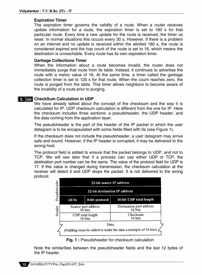
Garbage Collections Timer When the information about a route becomes invalid, the router does not immediately purge that route from its table. Instead, it continues to advertise the route with a metric value of 16. At the same time, a timer called the garbage collection timer is set to 120 s for that route. When the count reaches zero, the route is purged from the table. This timer allows neighbors to become aware of the invalidity of a route prior to purging. CheckSum Calculation in UDP We have already talked about the concept of the checksum and the way it is calculated for IP. UDP checksum calculation is different from the one for IP. Here the checksum includes three sections: a pseudoheader, the UDP header, and the data coming from the application layer.
The pseudoheader is the part of the header of the IP packet in which the user datagram is to be encapsulated with some fields filled with 0s (see Figure 1).
If the checksum does not include the pseudoheader, a user datagram may arrive safe and sound. However, if the IP header is corrupted, it may be delivered to the wrong host.
The protocol field is added to ensure that the packet belongs to UDP, and not to TCP. We will see later that if a process can use either UDP or TCP, the destination port number can be the same. The value of the protocol field for UDP is 17. If this value is changed during transmission, the checksum calculation at the receiver will detect it and UDP drops the packet. It is not delivered to the wrong protocol. Note the similarities between the pseudoheader fields and the last 12 bytes of the IP header.
3. (a)
Fig. 1 : Pseudoheader for checksum calculation
Prelim Question Paper Solution
0414/BSc/IT/TY/Pre_Pap/2014/IT_Soln 13
TCP Services Following are various TCP services : Stream Delivery Service : TCP, unlike UDP, is a stream-oriented protocol.
In UDP, a process (an application program) sends a chunk of bytes to the UDP for delivery. UDP adds its own header to this chunk of data, which is now called a datagram, and delivers it to the IP for transmission. The process may deliver several chunks of data to the UDP, but UDP treats each chunk independently without seeing any connection between them.
TCP, on the other hand, allows the sending process to deliver data as a stream of bytes and the receiving process to obtain data as a stream of bytes. TCP creates an environment in which the two processes seem to be connected by an imaginary “tube” that carries their data across the Internet. This imaginary environment is depicted in
Figure 1 : The sending process produces the stream of bytes and the receiving process consumes it.
Sending and Receiving Buffers : Because the sending and the receiving
processes may not produce and consume data at the same speed, TCP needs buffers for storage. There are two buffers, the sending buffer and the receiving buffer, for each direction. (We will see later that these buffers are also used in flow- and error-control mechanisms used by TCP.) One way to implement a buffer is to use a circular array of 1-byte locations as shown in figure 2. For simplicity, we have shown two buffers of 20 bytes each; normally the buffers are hundreds or thousands of bytes, depending on the implementation. We also show the buffers as the same size, which is not always the case.
3. (b)
Fig. 2 : Sending and receiving buffers
Fig. 1 : Stream delivery
Vidyalankar : T.Y. B.Sc. (IT) IT
0414/BSc/IT/TY/Pre_Pap/2014/IT_Soln 14
The figure shows the movement of the data in one direction. At the sending site, the buffer has three types of locations. The white Section contains empty locations that can be filled by the sending process (producer). The gray area holds bytes that have been sent but not yet acknowledged. TCP keeps these bytes in the buffer until it receives an acknowledgment. The colored area are bytes to be sent by the sending TCP. However, as we will see later in this chapter, TCP may be able to send only part of this colored section. This could be due to the slowness of the receiving process or perhaps to congestion in the network. Also note that after the bytes in the gray locations are acknowledged, the location is recycled and available for use by the sending process. This is why we show a circular buffer.
The operation of the buffer at the receiver site is simpler. The circular buffer is divided into two areas (shown as white and colored). The white area contains empty locations to be filled by bytes received from the network. The colored sections contain received bytes that can be consumed by the receiving process. When a byte is consumed by the receiving process, the location is recycled and added to the pool of empty locations.
Segments : Although buffering handles the disparity between the speed of
the producing and consuming processes, we need one more step before we can send data. The IP layer, as a service provider for TCP, needs to send data in packets, not as a stream of bytes. At the transport layer, TCP groups a number of bytes together into a packet called a segment. TCP adds a header to each segment (for control purposes) and delivers the segment to the IP layer for transmission. The segments are encapsulated in an IP datagram and transmitted. This entire operation is transparent to the receiving process. Later we will see that segments may be received out of order, lost, or corrupted and resent. All of these are handled by TCP with the receiving process unaware of any activities. Figure 10 shows how segments are created from the bytes in the buffers.
Note that the segments are not necessarily the same size. In the figure, for simplicity, we show one segment carrying 3 bytes and the other carrying 5 bytes. In reality segments carry hundreds if not thousands of bytes.
Full-Duplex Service : TCP offers full-duplex service, where data can flow in both directions at the same time. Each TCP then has a sending and receiving buffer and segments are sent in both direction.
Fig. 3 : TCP segments
Prelim Question Paper Solution
0414/BSc/IT/TY/Pre_Pap/2014/IT_Soln 15
Connection-Oriented Service : TCP, unlike UDP is a connection-oriented protocol. When a process at site A wants to send and receive data from another process at site B, the following occurs : i) A’s TCP informs B’s TCP and gets approval from B's TCP. ii) A’s TCP and B's TCP exchange data in both directions. iii) After both processes have no data left to send and the buffers are empty,
the two TCPs destroy their buffers.
Note that this is a virtual connection, not a physical connection. The TCP segment is encapsulated in an IP datagram and can be sent out of order, or lost, or corrupted, and then resent. Each may use a different path to reach the destination. There is no physical connection. However, because TCP creates a stream-oriented environment in which it accepts the responsibility of delivering the bytes in order to the other site, the situation is similar to creating a bridge that spans multiple islands and passing all of the bytes from one island to another in one single connection.
Reliable Service : TCP is a reliable transport protocol. It uses an
acknowledgment mechanism to check the safe and sound arrival of data. We will discuss this feature further in the section on error control.
Numbering Bytes Although the TCP software keeps track of the segment being transmitted or received, there is no field for a segment number value. Instead, there are two fields called the sequence number and the acknowledgment number. These two fields refer to the byte number not the segment number. Byte Numbers TCP numbers all data bytes that are transmitted in a connection. Numbering is independent in each direction. When TCP receives bytes of data from the process and stores them in the sending buffer, it numbers them. The numbering does not necessarily start from 0 ; it starts randomly. TCP generates a random number between 0 and 2 - 1 for the number of the first byte. For example, if the random number happens to be 1,057 and the total data to be sent is 6,000 bytes, the bytes are numbered from 1,057 to 7,056. We will see that byte numbering is used for flow and error control.
The bytes of data being transferred in each connection are numbered by TCP. The numbering starts with a randomly generated number. Sequence Number After the bytes have been numbered, TCP assigns a sequence number to each segment that is being sent. The sequence number for each segment is the number of the first byte carried in that segment.
Acknowledgment Number As we discussed before, communication in TCP is full duplex; when a connection is established, both parties can send and receive data at the same time. Each party numbers the bytes, usually with a different starting byte number. The sequence number in each direction shows the number of the first byte carried by the segment. Each party also uses an acknowledgment number to confirm the bytes it has received. However, the acknowledgment number defines the number
Vidyalankar : T.Y. B.Sc. (IT) IT
0414/BSc/IT/TY/Pre_Pap/2014/IT_Soln 16
of the next byte that the party expects to receive. In addition, the acknowledgment number is cumulative, which means that the party takes the number of the last byte that it has received, safe and sound, adds 1 to it, and announces this sum as the acknowledgment number. The term cumulative here means that if a party uses 5,643 as an acknowledgment number, it has received all bytes from the beginning up to 5,642. Note that this does not mean that the party has received 5,642 bytes because the first byte number does not have to start from 0.
Syndrome Created by the Sender The sending TCP may create a silly window syndrome if it is serving an application program that creates data slowly, for example, 1 byte at a time. The application program writes 1 byte at a time into the buffer of the sending TCP. If the sending TCP does not have any specific instructions, it may create segments containing 1 byte of data. The result is a lot of 41-byte segments that are traveling through an internet.
The solution is to prevent the sending TCP from sending the data byte by byte. The sending TCP must be forced to wait as it collects data to send in a larger block. How long should the sending TCP wait? If it waits too long, it may delay the process. If it does not wait long enough, it may end up sending small segments. Nagle found an elegant solution. Nagle’s Algorithm Nagle’s algorithm is very simple, but it solves the problem. This algorithm is for the sending TCP: i) The sending TCP sends the first piece of data it receives from the sending
application program even if it is only 1 byte. ii) After sending the first segment, the sending TCP accumulates data in the
output buffer and waits until either the receiving TCP sends an acknowledgment or until enough data has accumulated to fill a maximum-size segment. At this time, the sending TCP can send the segment.
iii) Step 2 is repeated for the rest of the transmission. Segment 3 must be sent if an acknowledgment is received for segment 2 or enough data is accumulated to fill a maximum-size segment.
The elegance of Nagle's algorithm is in its simplicity and in the fact that it takes into account the speed of the application program that creates the data and the speed of the network that transports the data. If the application program is faster than the network, the segments are larger (maximum-size segments). If the application program is slower than the network, the segments are smaller (less than the maximum segment size). Corrupted Segment Figure 1 shows a corrupted segment arriving at the destination. In this example the source sends segments 1 through 3, each 200 bytes. The sequence number begins at 1,201 on segment 1. The receiving TCP receives segments 1 and 2 and, using the checksum, finds them error free. It acknowledges the receipt of segments 1 and 2 using acknowledgment number 1,601, which means that it has received bytes 1,201 to 1,600 safe and sound, and is expecting to receive byte 1,601. However, it finds that segment 3 is corrupted and discards segment 3.
3. (c)
3. (d)
Prelim Question Paper Solution
0414/BSc/IT/TY/Pre_Pap/2014/IT_Soln 17
Fig. 1 : Corrupted segment
Note that although it has received bytes 1,601 to 1,800 in segment 3, the destination does not consider this as a "receipt" because this segment was corrupted. After the timer for segment 3 has matured, the source TCP will resend segment 3. After receiving segment 3, the destination sends an acknowledgment for byte 1,801, which indicates that it has received bytes 1,201 to 1,800 safe and sound. DHCP Client Transition Diagram
Fig. 1 : DHCP client transition diagram.
4. (a)
Vidyalankar : T.Y. B.Sc. (IT) IT
0414/BSc/IT/TY/Pre_Pap/2014/IT_Soln 18
Recursive Resolution of DNS Figure 1 shows the recursive resolution. The client (resolver) can ask for a recursive answer from a name server. This means that the resolver expects the server to supply the final answer. If the server is the authority for the domain name, it checks it database and responds. If the server is not the authority, it sends the request to another server (the parent usually) and waits for the response. If the parent is the authority, it responds; otherwise, it sends the query to yet another server. When the query is finally resolved, the response travels back until it finally reaches the requesting client.
Fig. 1 : Recursive resolution.
Types of DNS Messages DNS has two types of messages: query and response. Both types have the same format. The query message consists of a header and question records; the response message consists of a header, question records, answer records, authoritative records, and additional records (see Figure 1).
Fig. 1 : Query and response messages.
DHCP Packet Format techniques Figure 1 shows the format of a DHCP packet.
4. (b)
4. (c)
4. (d)
Prelim Question Paper Solution
0414/BSc/IT/TY/Pre_Pap/2014/IT_Soln 19
Fig. 1: DHCP packet format.
The following briefly describes each field: Operation code. This 8bit field defines the type of DHCP packet: request
(1) or reply (2). Hardware type. This is an 8bit field defining the type of physical network.
Each type of network has been assigned an integer. For example, for Ethernet the value is 1.
Hardware length. This is an 8bit field defining the length of the physical
address in bytes. For example, for Ethernet the value is 6. Hop count. This is an 8bit field defining the maximum number of hops the
packet can travel. Transaction ID. This is a 4byte field carrying an integer. The transaction
identification is set by the client and is used to match a reply with the request. The server returns the same value in its reply.
Number of seconds. This is a 16bit field that indicates the number of
seconds elapsed since the time the client started to boot. Flag. This is a 16bit field in which only the leftmost bit is used and the rest
of the bits should be set to 0s. A leftmost bit specifies a forced broadcast reply (instead of unicast) from the server. It the reply were to be unicast to the client, the destination IP address of the IP packet is the address assigned to the client. Since the client does not know its IP address, it may discard the packet. However, if the IP datagram is broadcast, every host will receive and process the broadcast message. Figure 2 shows the flag format.
Vidyalankar : T.Y. B.Sc. (IT) IT
0414/BSc/IT/TY/Pre_Pap/2014/IT_Soln 20
Fig. 2 : Flag format.
Client IP address. This is a 4byte field that contains the client IP address. If
the client does not have this information, this field has a value of 0.
Your IP address. This is a 4byte field that contains the client IP address. It is filled by the server (in the reply message) at the request of the client.
Server IP address. This is a 4byte field containing the server IP address. It is filled by the server in a reply message.
Gateway IP address. This is a 4byte field containing the IP address of a router. It is filled by the server in a reply message.
Client hardware address. This is the physical address of the client. Although the server can retrieve this address from the frame sent by the client, it is more efficient if the address is supplied explicitly by the client in the request message.
Server name. This is a 64byte that is optionally filled by the server in a reply packet. It contains a nullterminated string consisting of the domain name of the server. If the server does not want to fill this field with data, the server must fill it with all 0s.
Boot filename. This is a 128byte field that can be optionally filled by the server in a reply packet. It contains a null terminated string consisting of the full pathname of the boot file. The client can use this path to retrieve other booting information. It the server does not want to fill this field with data, the server must fill it with all 0s.
Options. This is a 64byte field with a dual purpose. It can carry either additional information (such as the network mask or default router address) or some specific vendor information. The field is used only in a reply message. The server uses a number, called a magic cookie, in the format of an IP address with the value of 99.130.83.99. When the client finishes reading the message, it looks for his magic cookie. If present, the next 60 bytes are options. An option is composed of three fields: a 1byte tag field, a 1byte length field, and a variablelength value field. The length field defines the length of the value field, not the whole option. See Figure 3.
Fig. 3 : Option format
Prelim Question Paper Solution
0414/BSc/IT/TY/Pre_Pap/2014/IT_Soln 21
The list of options is shown in Table 1. Table 1 : Options for DHCP.
Tag Length Value Description 0 Padding 1 4 Subnet mask Subnet mask 2 4 Time of the day Time offset 3 Variable IP addresses Default router 4 Variable IP addresses Time server 5 Variable IP addresses IEN 16 server 6 Variable IP addresses DNS server 7 Variable IP addresses Log server 8 Variable IP addresses Quote server 9 Variable IP addresses Print server 10 Variable IP addresses Impress 11 Variable IP addresses RLP server 12 Variable DNS name Host name 13 2 Integer Boot file size 53 1 Discussed later Used for dynamic configuration
128254 Variable Specific information Vendor specific 255 End of list
The lengths of the fields that contain IP addresses are multiples of 4 bytes. The padding option, which is only 1 byte long, is used only for alignment. The endoflist option, which is also only 1 byte long, indicates the end of the option field. Vendors can use option tags 128 to 254 to supply extra information in a reply message. Character Mode In the character mode, each character typed is sent by the client to the server. The server normally echoes the character back to be displayed on the client screen. In this mode the echoing of the character can be delayed if the transmission time is long (such as in a satellite connection). It also creates overhead (traffic) for the network because three TCP segments must be sent for each character of data: The user enters a character that is sent to the server. The server acknowledge the received character and echoes the character
back (in one segment). The client acknowledges the receipt of the echoed character. Example 1 In this example, we use the default mode to show the concept and its deficiencies even though it is almost obsolete today. The client and the server negotiate the terminal type and terminal speed and then the server checks the login and password of the user (see Figure 1).
5. (a)
Vidyalankar : T.Y. B.Sc. (IT) IT
0414/BSc/IT/TY/Pre_Pap/2014/IT_Soln 22
Components of SSH (SECURE SHELL) Another popular remote login application program is Secure Shell (SSH). SSH, like TELNET, uses TCP as the underlying transport protocol, but SSH is more secure and provides more service than TELNET.
Versions There are two versions of SSH: SSH1 and SSH2, which are totally incompatible. The first version, SSH1 is now deprecated because of security flaws in it. In this section, we discuss only SSH2. Components SSH is a proposed applicationlayer protocol with four components, as shown in Figure 1.
Fig. 1 : Components of SSH.
5. (b)
Fig. 1 : Example 1
Prelim Question Paper Solution
0414/BSc/IT/TY/Pre_Pap/2014/IT_Soln 23
SSH TransportLayer Protocol (SSHTRANS) Since TCP is not a secured transport layer protocol, SSH first uses a protocol that creates a secured channel on the top of TCP. This new layer is an independent protocol referred to as SSHTRANS. When the software implementing this protocol is called, the client and server first use the TCP protocol to establish an insecure proconnection. Then they exchange several security parameters to establish a secure channel on the top of the TCP. We briefly list the services provided by this protocol: Privacy or confidentiality of the message exchanged. Data integrity, which means that it is guaranteed that the messages
exchanged between the client and server are not changed by an intruder. Server authentication, which means that the client is now sure that the server
is the one that it claims to be. Compression of the messages that improve the efficiency of the system and
makes attack more difficult. SSH Authentication Protocol (SSHAUTH)
After a secure channel is established between the client and the server and the server is authenticated for the client, SSH can call another software that can authenticate the client for the server. SSH Connection Protocol (SSHCONN) After the secured channel is established and both server and client are authenticated for each other, SHH can call a piece of software that implements the third protocol, SSHCONN. One of the services by the SSHCONN protocol is to do multiplexing. SSHCONN takes the secure channel established by the two previous protocols and lets the client create multiple logical channels over it. SSH Applications After the connection phase is completed, SSH allows several application programs to use the connection. Each application can create a logical channel as described above and then benefit from the secured connection. In order words, remote login is one of the services that can use the SSHCONN protocols; other applications, such as a file transfer application can use one of the logical channels for this purpose. File management commands. These commands let the user access the file system on the remote computer. They allow the user to navigate through the directory structure, create new directories, delete files, and so on. Table 7 gives common commands in this group. Table 1 : File management commands. Command Arguments(s) DescriptionCWD Directory name Change to another directoryCDUP Change to parent directoryDELE File name Delete a fileLIST Directory name List subdirectories of filesNLIST Directory name List subdirectories or files without attributes
5. (c)
Vidyalankar : T.Y. B.Sc. (IT) IT
0414/BSc/IT/TY/Pre_Pap/2014/IT_Soln 24
MKD Directory name Create a new directoryPWD Display name of current directory RMD Directory name Delete a directoryRNFR File name (old) Identify a file to be renamedRNTO File name (new) Rename the fileSMNT File system name Mount a file system
RRQ and WRQ Messages of TFTP Messages There are five types of TFTP messages, RRQ, WRQ, DATA, ACK and ERROR, as shown in Figure 1.
Fig. 1 : Message categories.
RRQ : The read request (RRQ) message is used by the client to establish a
connection for reading data from the server. Its format is shown in Figure 2.
Fig. 2 : RRQ format
The RRQ message fields are as follows: OpCode : The first field is a 2-byte operation code. The value is 1 for the RRQ message. File name : The next field is a variable-size string (encoded in ASCII) that defines the name of the file. Since the file name varies in length, termination is signaled by a 1-byte field of 0s. Mode : The next field is another variable-size string defining the transfer mode. The mode field is terminated by another 1-byte field of 0s. The mode can be one of two strings: "netascii" (for an ASCII file) or "octet" (for a binary file). The file name and mode fields can be in upper- or lowercase, or a combination of both.
WRQ : The write request (WRQ) message is used by the client to establish a connection for writing data to the server. The format is the same as RRQ except that the OpCode is 2 (see Figure 3).
Fig. 3 : WRQ format
5. (d)
Prelim Question Paper Solution
0414/BSc/IT/TY/Pre_Pap/2014/IT_Soln 25
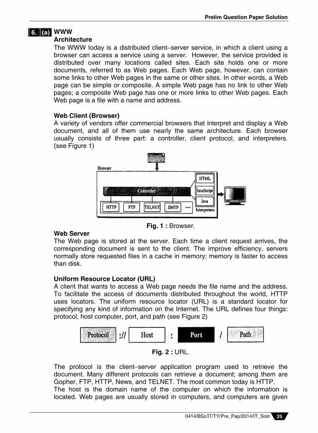
WWW Architecture The WWW today is a distributed clientserver service, in which a client using a browser can access a service using a server. However, the service provided is distributed over many locations called sites. Each site holds one or more documents, referred to as Web pages. Each Web page, however, can contain some links to other Web pages in the same or other sites. In other words, a Web page can be simple or composite. A simple Web page has no link to other Web pages; a composite Web page has one or more links to other Web pages. Each Web page is a file with a name and address. Web Client (Browser) A variety of vendors offer commercial browsers that interpret and display a Web document, and all of them use nearly the same architecture. Each browser usually consists of three part: a controller, client protocol, and interpreters. (see Figure 1)
Fig. 1 : Browser.
Web Server The Web page is stored at the server. Each time a client request arrives, the corresponding document is sent to the client. The improve efficiency, servers normally store requested files in a cache in memory; memory is faster to access than disk. Uniform Resource Locator (URL) A client that wants to access a Web page needs the file name and the address. To facilitate the access of documents distributed throughout the world, HTTP uses locators. The uniform resource locator (URL) is a standard locator for specifying any kind of information on the Internet. The URL defines four things: protocol, host computer, port, and path (see Figure 2)
Fig. 2 : URL.
The protocol is the clientserver application program used to retrieve the document. Many different protocols can retrieve a document; among them are Gopher, FTP, HTTP, News, and TELNET. The most common today is HTTP. The host is the domain name of the computer on which the information is located. Web pages are usually stored in computers, and computers are given
6. (a)
Vidyalankar : T.Y. B.Sc. (IT) IT
0414/BSc/IT/TY/Pre_Pap/2014/IT_Soln 26
domain name aliases that usually begin with the characters “www”. This is not mandatory, however, as the host can have any domain name. The URL can optionally contain the port number of the server. If the port is included, it is inserted between the host and the path, and it is separated from the host by a colon. Path is the pathname of the file where the information is located. Note that the path can itself contain slashes that, in the UNIX operating system, separate the directories from the subdirectories and files. In other words, the path defines the complete file name where the document is stored in the directory system. Use of Cookies The World Wide Web was originally designed as a stateless entity. A client sends a request; a server responds. Their relationship is over. The original design of WWW, retrieving publicly available documents, exactly fits this purpose. Today the Web has other functions; some are listed below: Websites are being used as electronic stores that allow users to browse
through the store, select wanted items, put them in an electronic cart, and pay at the end with a credit card.
Some websites need to allow access to registered clients only. Some websites are used as portals: The user selects the Web pages he wants
to see. Some websites are just advertising. For these purposes, the cookie mechanism was devised. Creating and Storing Cookies : The creation and storing of cookies depend
on the implementation; however, the principle is the same. 1) When a server receives a request from a client, it stores information
about the client in a file or a string. The information may include the domain name of the client, the contents of the cookie (information the server has gathered about the client such as name, registration number, and so on), a timestamp, and other information depending on the implementation.
2) The server includes the cookie in the response that it sends to the client. 3) When the client receives the response, the browser stores the cookie in
the cookie directory, which is sorted by the domain server name.
Using Cookies : When a client sends a request to a server, the browser looks in the cookie directory to see if it can find a cookie sent by that server. If found, the cookie is included in the request. When the server receives the request, it knows that this is an old client, not a new one. Note that the contents of the cookie are never read by the browser or disclosed to the user. It is a cookie made by the server and eaten by the server. Now let us see how a cookie is used for the four previously mentioned purposes: 1) An electronic store (e-commerce) can use a cookie for its client
shoppers. When a client selects an item and inserts it into a cart, a cookie that contains information about the item, such as its number and unit price, is sent to the browser. If the client selects a second item, the cookie is updated with the new selection information. And so on. When
6. (b)
Prelim Question Paper Solution
0414/BSc/IT/TY/Pre_Pap/2014/IT_Soln 27
the client finishes shopping and wants to check out, the last cookie is retrieved and the total charge is calculated.
2) The site that restricts access to registered clients only sends a cookie to the client when the client registers for the first time. For any repeated access, only those clients that send the appropriate cookie are allowed.
3) A Web portal uses the cookie in a similar way. When a user selects her favorite pages, a cookie is made and sent. If the site is accessed again, the cookie is sent to the server to show what the client is looking for.
4) A cookie is also used by advertising agencies. An advertising agency can place banner ads on some main website that is often visited by users. The advertising agency supplies only a URL that gives the banner address instead of the banner itself. When a user visits the main website and clicks the icon of an advertised corporation, a request is sent to the advertising agency. The advertising agency sends the banner, a GIF file for example, but it also includes a cookie with the ID of the user. Any future use of the banners adds to the database that profiles the Web behavior of the user. The advertising agency has compiled the interests of the user and can sell this information to other parties. This use of cookies has made them very controversial. Hopefully, some new regulations will be devised to preserve the privacy of users.
Active Documents of WWW For many applications, we need a program or a script to be run at the client site. These are called active documents. For example, suppose we want to run a program that creates animated graphics on the screen or a program that interacts with the user. The program definitely needs to be run at the client site where the animation or interaction takes place. When a browser requests an active document, the server sends a copy of the document or a script. The document is then run at the client (browser) site. Figure 1 shows how Java applets are used in the first method; the second is similar but needs two transactions.
Fig. 1 : Active document using Java applet. Header Lines in Request Message of HTTP After the request line, we can have zero or more request header lines. Each header line sends additional information from the client to the server. For example, the client can request that the document be sent in a special format. Each header line has a header name, a colon, a space, and a header value (see Figure 1). Table 1 shows some header names commonly used in a request. The value field
6. (c)
6. (d)
Vidyalankar : T.Y. B.Sc. (IT) IT
0414/BSc/IT/TY/Pre_Pap/2014/IT_Soln 28
defines the values associated with each header name. The list of values can be found in the corresponding RFCs.
Fig. 1 : Format of the request message
Table 1 : Request Header Names.
Header DescriptionUseragent Identifies the client programAccept Shows the media format the client can accept Acceptcharset Shows the character set the client can handle Acceptencoding Shows the encoding scheme the client can handle Acceptlanguage Shows the language the client can acceptAuthorization Shows what permissions the client hasHost Shows the host and port number of the client Date Shows the current dateUpgrade Specifies the preferred communication protocol Cookie Returns the cookie to the serverIfModifiedSince Returns the cookie to the server