Page 1
HAL Id: hal-00849751https://hal.archives-ouvertes.fr/hal-00849751
Submitted on 1 Aug 2013
HAL is a multi-disciplinary open accessarchive for the deposit and dissemination of sci-entific research documents, whether they are pub-lished or not. The documents may come fromteaching and research institutions in France orabroad, or from public or private research centers.
L’archive ouverte pluridisciplinaire HAL, estdestinée au dépôt et à la diffusion de documentsscientifiques de niveau recherche, publiés ou non,émanant des établissements d’enseignement et derecherche français ou étrangers, des laboratoirespublics ou privés.
Vibration reduction of a single cylinder reciprocatingcompressor based on multi-stage balancing
Nadège Levecque, Jarir Mahfoud, Denis Violette, Guy Ferraris, Régis Dufour
To cite this version:Nadège Levecque, Jarir Mahfoud, Denis Violette, Guy Ferraris, Régis Dufour. Vibration reduction ofa single cylinder reciprocating compressor based on multi-stage balancing. Mechanism and MachineTheory, Elsevier, 2010, 46 (1), pp.1-9. 10.1016/j.mechmachtheory.2010.09.004. hal-00849751
Page 2
1
VIBRATION REDUCTION OF A SINGLE CYLINDER
RECIPROCATING COMPRESSOR BASED ON MULTI-STAGE
BALANCING
AUTHORS:
N. LEVECQUE*, J. MAHFOUD*, D. VIOLETTE**, G. FERRARIS* and R. DUFOUR*
*Université de Lyon, CNRS, INSA-Lyon, LaMCoS UMR5259, F69621, Villeurbanne,
France
** Danfoss Commercial Compressors, F01600, France.
COMPLETE ADDRESS OF CORRESPONDING AUTHOR:
Dr Jarir Mahfoud
Université de Lyon, CNRS, INSA Lyon, LaMCoS - UMR 5259, 8, rue des Sciences,
69621 Villurbanne Cedex, France
Phone: 33 – 4.72.43.89.39, Fax: 33 – 4.72.43.89.30,
[email protected]
The manuscript contains 29 double-spaced pages, 3 tables and 8 figures
*Manuscript
Click here to view linked References
Page 3
2
ABSTRACT
Basically, a reciprocating compressor consists of three main mechanical subsets: the
hermetic housing, the crankcase and the rotor-crankshaft assembly. The
counterweight mass located on the rotor-crankshaft is designed to balance the
eccentric masses of the slider-crank mechanism which predominate in comparison to
the residual distributed unbalance masses due to manufacturing. However, excessive
vibration levels can be observed. The objective of the study is to perform a reliable
finite element model for balancing the compressor by taking into account the dynamic
behavior of the three subsets. The rotor-crankshaft assembly is considered as a
flexible body, while the crankcase and the housing are assumed to be rigid. The
rotor-crankshaft model is updated by using experimental modal analysis at rest. The
characteristics of the fluid film bearings are speed of rotation dependant. The forces
of the pressure and of the slider-crank mechanism are expanded by using Fourier
transformation. The Influence Coefficient Method is used to investigate several
balancing solutions to reduce the vibratory levels of the target plane located on the
three main subsets. The experiments carried out show that this multi-stage balancing
procedure is rather more efficient than a classical approach based only on the
dynamic balancing of the rotor crankshaft assembly.
KEYWORDS:
Balancing, Dynamic behavior, Compressor, Finite element, Experiments.
Page 4
3
1- INTRODUCTION
Single cylinder reciprocating compressors are widely used in several types of
refrigerant applications. They are driven by an asynchronous electrical motor and
their operating speed depends on the power supply frequency (50 or 60 Hz).
Generally speaking, they consist of three main subsets: (1) a slider crank mechanism
composed of a piston, a connecting rod, a crankshaft equipped with a counterweight
mass and an electrical rotor, (2) a crankcase equipped with an electrical stator and
(3) hermetic housing. These subsets are linked altogether by different types of
suspension: the crankshaft is linked to the crankcase by two fluid film bearings and
an air gap, the crankcase is linked to the housing by springs and, lastly, the housing
is linked to the frame by grommets and by suction and discharge pipes. In brief, a
single cylinder compressor is a multi-stage system subject to vibration even after
balancing has been carried out.
In order to reduce the effect of the eccentric masses (crankpin and crank arm
masses, rotating mass of the connecting rod), static balancing consists in positioning
a counterweight in a plane close to the connecting rod plane. To avoid excitation of
the moment due to the offset of these two planes, another balancing plane,
positioned classically on the electrical rotor, is used for dynamic balancing. Therefore
dynamic balancing has to be carried out on the crankshaft equipped with the
electrical rotor and a ring whose mass is equivalent to the rotating masses.
Unfortunately, such a balancing does not take into account the dynamic behavior of
the three main subsets. Consequently, the responses of the latter can be over-
pronounced. Noise and mechanical problems can occur, such as rotor-to-stator or
bearing rubbing and failures at pipe weld spots.
Page 5
4
Complementing the balancing techniques, several technological solutions
have been proposed to obtain optimal vibration reduction. Mention can be made of
attempts to optimize the locations of the counterweight and the internal suspensions
[1], and to introduce a piston axis offset [2]. Moreover, the multistage balancing
method presented in [3, 4] was applied to rotary compressors composed of two
subsets.
The objective of the study is to develop a simple balancing procedure for the
operators that could be applied on a single cylinder reciprocating compressors. It
aims at the reduction of the vibration levels of the three subsets constituting the
compressor. This type of compressor has the advantage to be efficient and cheap, so
the additional cost due to balancing must be negligible. The method developed is a
model based balancing method taking into account the geometrical definition of the
different compressor elements. The magnetic attraction forces and the interaction
between the three subsets constituting the compressor are considered.
The initial unbalances are mainly due to the eccentric masses of the
crankshaft (crank-pin, crank-arms, counterweight, etc.) and of the rotating part of the
connecting rod. The alternative part of the connecting rod, added with piston ring and
pin masses are in a translation movement and cannot be fully balanced by a rotating
mass. The geometrical dispersion, of the rotating part, measured was found to be
less than 5%. The main contribution of this dispersion concerns the eccentric mass
and too particularly the counterweight mass.
Consequently, the residual unbalance distributed masses due to
manufacturing are neglected.
Section 2 focuses on the data of a refrigeration compressor to illustrate the
balancing approach. The Finite Element (FE) models of the three subsets are
Page 6
5
combined with rotordynamics theory, see Section 2. Moreover, the constant and
synchronous terms of the forcing excitations are taken into account. The Fourier
expansion of the slider-crank forces provides constant, synchronous and non
synchronous forces. The constant force permits evaluating the bearing
characteristics which are speed of rotation dependent. The synchronous force is
used for the balancing and combined with the sup-synchronous forces for predicting
the mass unbalance response (Section 3). The influence coefficient technique
provides multi-stage balancing based on two speeds of rotation, two correction
planes and several target planes located on the three subsets and especially at the
anchorage points on the housing of the suction and discharge pipes. The corrective
mass calculated by the proposed multi-stage balancing based on a model and by
classical dynamic balancing based on experimental tests carried out only on the
equivalent rotating part, are implemented in two identical compressor prototypes. The
proposed balancing efficiency is investigated by analyzing the measured steady state
mass unbalance responses of the two prototypes under several operating conditions.
Then the advantages and the limitations of the proposed multi-stage balancing are
discussed.
2- SINGLE-CYLINDER REFRIGERANT COMPRESSOR
The compressor sketched in Fig.1 is composed of three subsets: the rotor-
crankshaft assembly, which is a rotating part; and the stator-crankcase assembly and
the hermetic housing, which are non rotating parts. The rotor-crankshaft assembly is
connected to the stator - crankcase assembly by the fluid film bearings and the
magnetic attraction between the electrical rotor and the stator. The crankcase is
connected to the hermetic housing by an internal suspension composed of springs
and the discharge pipe, and the housing is mounted on an external suspension
Page 7
6
composed of grommets and the suction and discharge pipes. The stiffness of the
pipes is assumed to be neglected regarding the stiffness of the springs and
grommets.
An industrial hermetic reciprocating single-cylinder refrigeration compressor is
investigated to illustrate the different steps of the proposed balancing approach. The
compressor chosen is able to run either at 50Hz or at 60 Hz and has a swept volume
of 68 cm3 by revolution. It provides a cooling capacity of 5.7 kW for a power input of
2.9 kW at 50Hz with an evaporating temperature of -10°C and a condensing
temperature of 45°C. The net mass of the compressor is 26 kg while the rotor-
crankshaft assembly, stator-crankcase assembly and housing have roughly the
following masses: 3.5 kg, 15 kg, and 7 kg, respectively.
3- FINITE-ELEMENT MODEL
3.1- Whole Compressor
The FE model, shown in Fig. 2, is governed by the rotordynamics theory
presented in [5]. Each node contains the four degrees of freedom (DOF) of the
bending motion: two lateral translations and the two associated rotations. The
rotating part, considered as flexural, is modeled with two node beam elements. The
rotor-crankshaft assembly and the hermetic housing are considered rigid and are
modeled with rigid beam elements. Their mass properties are modeled with
additional mass elements located at their centre of inertia. The bearings, that relate
the rotor to the crankcase assembly (nodes #30, 37 & 65 on Figure 2), are modeled
with two-node bearing elements whose stiffness and damping parameters are speed
of rotation dependent (modeling detailed in section 3.4). Side-pull forces between the
electric rotor and the stator are taken into account by using distributed additional two
Page 8
7
node elements (relating elements 51-56 of the stator and 3-8 of the electrical rotor)
with negative stiffness, [6]. The internal suspensions (relating the crankcase
assembly to the housing) and the grommets (relating the whole compressor to the
foundations) are modeled by using two-node elements, located on the rotor axis and
containing transverse and angular parameters. The modeling of the rotating parts is
detailed in the next section. After assembly, the unbalance response of the
compressor is governed by the matrix equations:
[ ] [ ( ) ( ) ] [ ( ) ] ( )R NR G B S R B SP S+ + Ω + Ω + + + Ω + + = ΩM M X C C C X K K K K X F , (1)
with Ω , being the constant speed of rotation, X the displacement vector containing
all the bending DOF of the assembly, RM and RK the classical mass and stiffness
matrices of the rotating part; ( )G ΩC , the non-symmetric gyroscopic matrix; ( )B ΩC and
( )B ΩK , the damping and stiffness matrices due to the bearings; NRM , the mass
matrix of the non-rotating parts; SK and SC , the stiffness and damping matrices
associated with the suspensions; SPK , the anti-stiffness matrix associated with the
side-pull forces. The external force vector ( , )nΩ ΩF ,
( , ) ( ) ( ) ( , )C CM P CRn n+
Ω Ω = Ω + Ω + Ω ΩF F F F , (2)
contains ( )C ΩF , the force vector due to the eccentric masses of the crankshaft,
( )CM ΩF , the force vector of the correction masses, and ( , )P CR n+
Ω ΩF the slider-crank
force vector related to the piston, connecting rod and cylinder pressure. In what
follows particular attention is paid to the rotating part, slider-crank forces and
bearings.
Page 9
8
3.2- Rotating part
Figure 3 represents the general modelling of the rotating parts with the used
elements (numbered from 1 to 41) and the corresponding nodes that are denoted by
italic underlined numbers. The rotor-crankshaft assembly is mainly modelled with 41
shaft elements. Rigid disk elements (D1 & D2) with a mean radius are used for
modelling the counterweight. Crankshaft dissymmetry is taken into account by
applying mass unbalances in response calculation. The crankpin assumes the
angular reference. Therefore the unbalance masses, with a 0° phase are located on
nodes (16, 19, 21, 23) to model the crankpin and crank-arm dissymmetry while
unbalance masses, with a 180° phase, are applied on nodes (13, 15) to consider the
counterweight. Consequently the total unbalance masses situated at 0° is 3983
g.mm, and at 180°, 4458 g.mm.
The FE model was updated by carrying out an experimental modal analysis on
a free-free rotor crankshaft assembly. The Roving hammer technique was used to
obtain the bending mode shapes with the data acquisition system LMS-CadaX. To
update the natural frequencies, the diameters of shaft elements corresponding to the
crank-pin and crank-arm (32 to 35) were reduced to make the elements more flexible.
It should be mentioned that this modification had no influence on the mass properties
since the shaft elements were modelled without mass and the mass effect was
considered with rigid disk elements (D3 for the mass effect of the crankpin, D4-D6 for
the mass effect of the different sections of the crank-arm).
The electrical rotor, made of steel laminations joined together with aluminium
bars, is fitted onto the crankshaft, made of cast iron. The material properties are
presented in Table 1.
Page 10
9
3.3- Slider-crank forces
The pressure force Pr is applied on the piston and on the crankcase and
transmitted to the crankshaft by the connecting rod. The transmitted forces are
denoted Qx and Qz (Fig. 4) and they vary with respect to the angular position ϑ .
Only the synchronous component of these forces is considered for the balancing
procedures. The constant component corresponds to the load supported by the
bearings. Let P, B, M, and O be the centres of the piston, of the connecting rod, of
the crank-pin and of the crankshaft, respectively. Let CRm , l, CRI , φ be the mass,
length, inertia, and auxiliary angle of the connecting rod. Consequently its alternative
and rotating masses are re CR
bm m
l= and ro CR
am m
l= . Let r be the eccentricity of the
crank-pin, px , and pm , the position and the mass of the piston. The angular position
of the crankpin is ϑ . The variable px is linked to ϑ the main variable of the
mechanism [7, 8] and depends on the cylinder volume. The transmitted force
components xQ and zQ have the following expressions:
2( )( ) cosx re p p ro rQ m m x m r Pϑ ϑ= + − + − , (3)
21( ) ( )( ) tan sin
cosz CR CR p re p r roQ I m ab m m x P m r
lφ φ ϑ ϑ
φ = − + + − − −
. (4)
The pressure diagram taken into account corresponds to the operating
condition corresponding to evaporating and condensation temperatures: -10°/45° C.
In order to extract the synchronous component of the efforts for the balancing
considerations, each force component is fitted first by fifteenth order polynomials
(Fig. 5) and then expanded in a Fourier series:
Page 11
10
0
1
( ) cos( ) sin( )N
k k
k
Q a a k b kϑ ϑ ϑ=
= + + , (5)
where the coefficients ka and kb are calculated by the coefficients of the
polynomials. The constant terms 0xa and 0za , corresponding to static forces, are
calculated for both the x and z-components: 0 2969xa = N, 0 218za = N. The
crankpin is loaded by the static force pF , given by:
2 2
0 0
11489
2p x zF a a N= + = (6)
For the higher order, the x-component coefficients are the largest and are the
only ones used in the compressor dynamics (Table 2). The z-component contributes
only on the constant term corresponding to the load supported by the bearings. The
compressor balancing procedure is based only on the first order coefficients.
3.4- Bearing characteristics
Stiffness and damping coefficients are evaluated by using the tables proposed
by Someya [9]. First of all, the Sommerfeld number S should be estimated. Let µ be
the oil film viscosity, θΩ = the speed of rotation, L, D, pC , F the length, the diameter,
the gap, and the static load of the bearing, respectively.
2
2 p
LD DS
F C
µ Ω=
(7)
The upper bearing is made of two bearing models (L/D~1, node #37 on Figure
2, and L/D~0.5, node 30) while the lower bearing has a ratio L/D~1 (node #65). The
reactions F on each bearing are deduced from relation (6). The stiffness and
damping coefficients of the three bearings are calculated for 3000 and 3600 r/min.
Page 12
11
4- PROPOSED MULTI-STAGE BALANCING
4.1- Influence Coefficient Method
The influence coefficients (IC) method is a well known experimental balancing
method [10]. It consists of evaluating the influence of trial masses on the
displacements at given planes, called measuring planes. The method assumes that
the displacements are linearly proportional to the trial weights and that the initial
unknown unbalance can be represented by a discrete finite number of unbalance
moments that are placed on chosen balancing planes [11, 12]:
ini ini=V C B . (8)
iniV is the vector of radial displacements due to the initial unknown unbalance
iniB . The elements of V and B contain magnitude and phase information with
respect to the reference phase, defined previously. C is the influence coefficient
matrix. The method aims at determining the balancing weights cB to be placed at the
chosen balancing planes so that the magnitudes of radial displacements, measured
at the measuring planes, are minimized for different speeds of rotation:
( ) 0ini c+ =C B B . (9)
Here, the IC method follows a numerical approach. The IC matrix represents
the system and is determined by using trial weights BT and by predicting the resulting
displacements VR at given planes, known as target planes here:
( )ini T R+ =C B B V , (10)
( )1
T R ini
−= −C B V V . (11)
Page 13
12
The correction weights are calculated either by direct inversion if the numbers
of balancing planes and of target planes are equal:
1
C ini
−= −B C V , (12)
or by least squares technique, if not [13, 14]:
1t t
C ini
−
= − B C C C V , (13)
where C represents the complex conjugate of matrix C .
4.2- Balancing procedure
The IC method with a numerical approach is applied on the compressor model
to determine the weights that reduce the vibrations on several target planes situated
on different subsets of the compressor. The crankshaft dissymmetry and the slider-
crank mechanism generate unbalance forces called initial unbalances. Only the
synchronous forces can be balanced, corresponding with the first order of the Fourier
series (Fig. 5). The planes at the top of the electrical rotor (BP1) and at the
counterweight (BP2) are available technologically in order to place corrective
weights. The aim is to reduce vibration levels especially in the target planes (TP1 –
TP7), where there are specific connections (pipe-housing, grommets-housing,
springs-crankcase) and the air gap, (Fig. 2). The calculation of the corrective weights
is done successively for single-plane balancing and for two-plane balancing, for one
speed (3000 or 3600 r/min) and for two speeds (3000 and 3600 r/min). The model
successively predicts the responses to the initial unbalances and to the trial weights
added to the initial unbalances. The initial unbalances and the calculated corrective
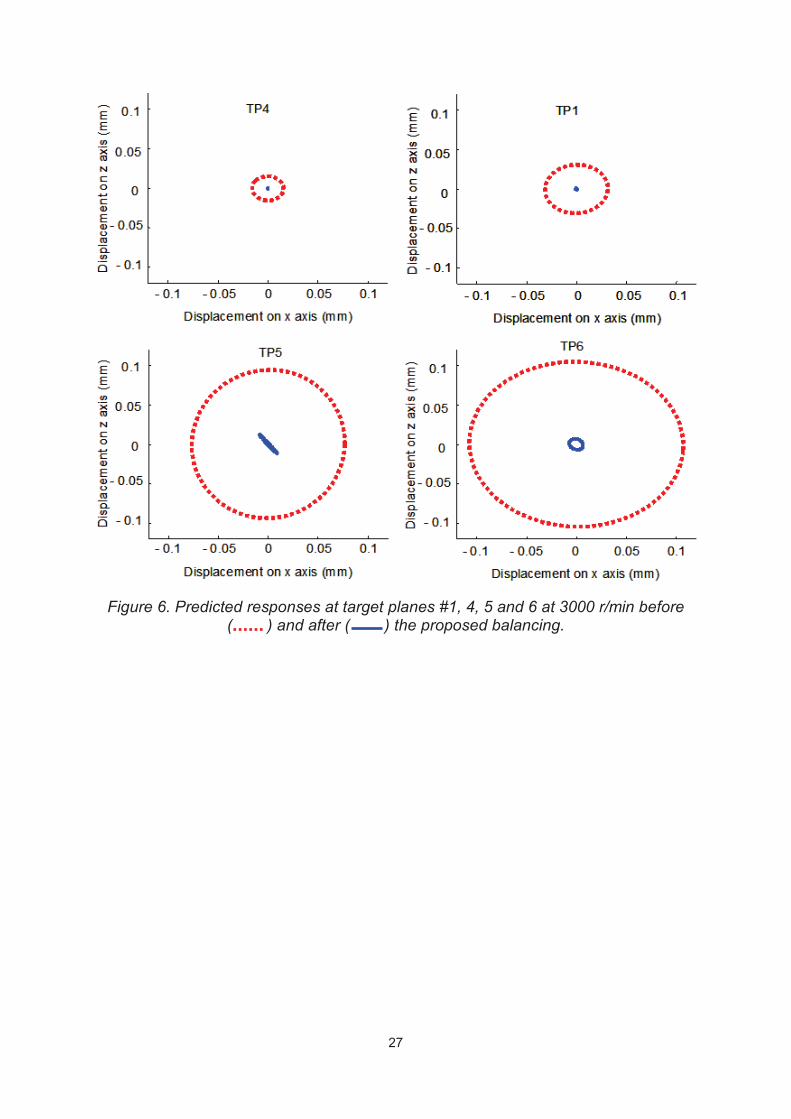
weights permit providing predicted responses at the target planes which are
compared to responses with the initial unbalances only, see Fig. 6.
Page 14
13
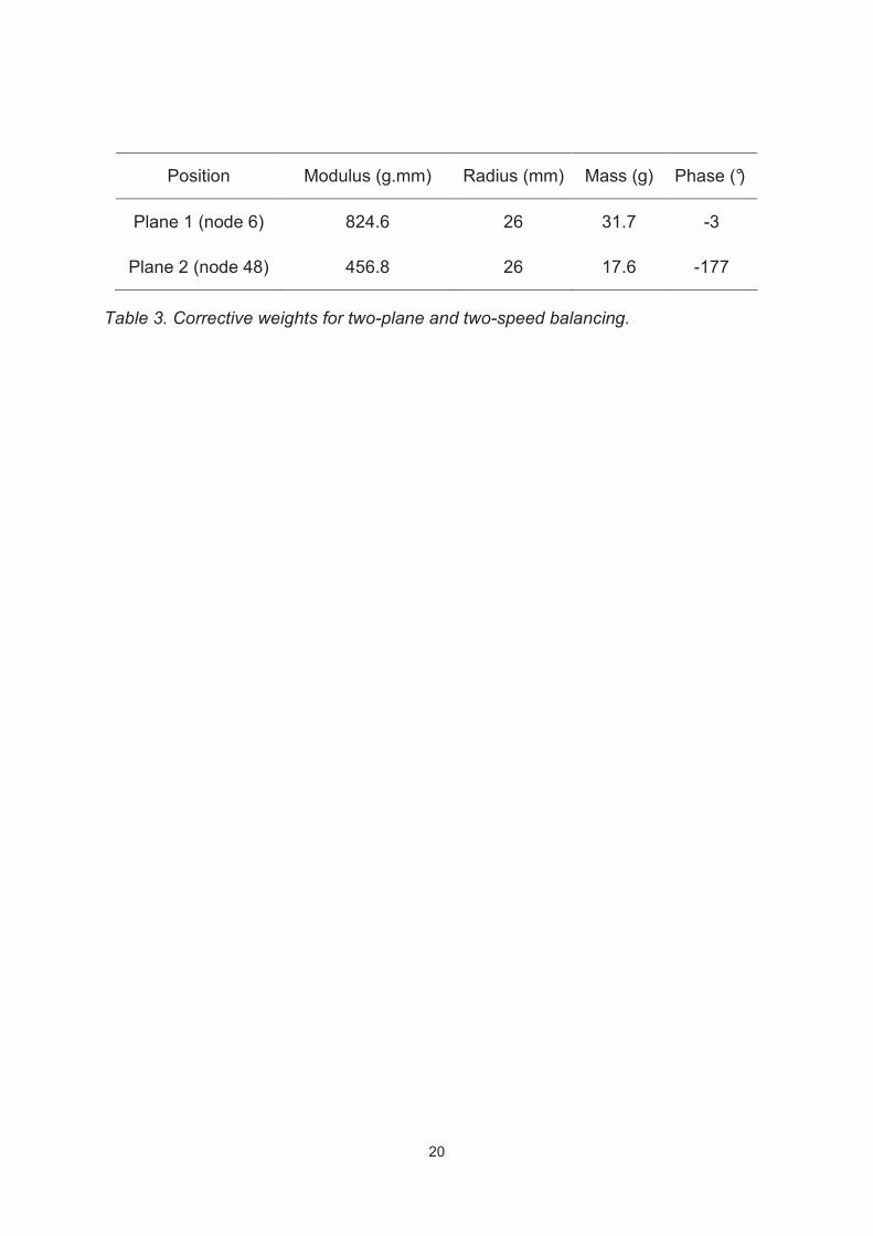
The multi-plane balancing is more efficient than the single-plane balancing.
The two-speed balancing, which is more convenient for 50 and 60 Hz operating
conditions, is not really less efficient than the one-speed balancing. The responses
calculated at 3000 r/min and at 3600 r/min are similar. Consequently only the results
at 3000 r/min for the two-plane and two-speed balancing are presented (Table 3, Fig.
6).
Considering the responses predicted by the model, the proposed balancing is
efficient, especially for the planes located on the housing. TP 2, TP 3 and TP 7
response planes are similar to the responses of TP 1 and TP 4 but they are not
presented here.
5- EXPERIMENTAL VALIDATION
The objective of the experimental investigation is to implement the proposed
multi-stage balancing in a compressor prototype #1 to evaluate its efficiency
regarding the classical dynamic balancing implemented in another similar
compressor prototype #2.
The classical dynamic balancing is carried out on the rotor-crankshaft
assembly by using a balancing machine, the two balancing planes described in
Section 3.2, and one speed (600 r/min). The balancing quality obtained corresponds
to the G6.3 class at 3000 r/min of the ISO standard.
The prototypes are mounted on a rigid frame by their grommets and by pipes
having a specific design with very low stiffness. The mass unbalance responses are
measured for different operating conditions by using three tri-axial accelerometers
stuck onto the hermetic housings at measurement points MP1 and MP3
Page 15
14
(corresponding to target point TP4 and MP2 (corresponding to target point TP1), see
Fig. 7. The piston axis is collinear to the Galilean x-axis, sketched in Fig.7.
The operating conditions took into account the two nominal speeds of rotation
corresponding to the 50 and 60 Hz frequencies, a constant condensation
temperature (+45°C) and an evaporation temperature varying from -20°C to +10°C:
20/45°, -15/45°, -10/45°, -5/45°, 0/45°, 5/45° and 10/45°. Fig. 8 collects the X-Y
vibration magnitudes measured on Prototypes #1 and #2. Amplitude values were
normalized with respect to the maximum value obtained.
The vibration levels of MP3 and MP2 along X and of MP1 along Y are low.
The vibration levels of MP3 along Y and of MP2 and MP1 along X are high.
Therefore it can be established that the steady state housing response is mainly
governed by the torsion mode shape around the vertical axis Z. Prototype #2
provides high vibration levels at the bottom of the housing (MP2). To sum up it can
be stated that the housing motion of Prototype #2 is composed of torsion and strong
conical mode shapes while the housing motion of Prototype #1 is composed of
torsion and low cylindrical mode shapes. Prototype #2 produces a high vibration level
in the plane located at the bottom where the grommets and discharge pipe are
connected. Moreover the operating conditions have almost no influence on the
motion of the housing of Prototype#1. Broadly speaking, Prototype #1 provides more
satisfactory dynamic behaviour than Prototype #2.
5- CONCLUSION
A numerical approach for balancing a single cylinder reciprocating compressor
has been presented. Vibration levels of its three subsets were considered and the
constant and synchronous terms of the excitations were taken into account. The
Page 16
15
proposed numerical balancing can be used for rotating machinery whose unbalance
masses are fairly well known. This is true for reciprocating compressors. Vibration
levels stemming from the proposed balancing were compared with those obtained
with a balancing machine and it was shown that this multi-stage balancing is rather
more efficient than a classical dynamic balancing focusing only on rotating parts. It
can be an alternative solution that saves time and reduces costs. Consequently, it is
important to study its sensitivity to production tolerances.
6- REFERENCES
[1]. K. Kjeldsen, P. Madsen, 1978, Proceeding of Purdue Compressor
Technology Conference, edited by James F. Hamilton 55-59. Reduction of
compressor vibration by optimizing the locations of the counterweight and the
internal springs
[2]. A. Kubota, T. Nagao, K. Tsuboi, T. Kakiuchi, 2006, International
publication number WO 2006/049108 A1. Reciprocating compressor
[3]. F. Sève, M.A. Andrianoely, A. Berlioz, R. Dufour, M. Charreyron, 2003,
Journal of Sound and Vibration, 264(2), 287-302. Balancing of machinery with
flexible variable-speed rotor
[4]. G. Ferraris, M.-A. Andrianoely, A. Berlioz and R. Dufour, 2006, Journal
of Sound and Vibration, 292, 3-5, 899-910. Influence of cylinder pressure on
the balancing of a rotary compressor
[5]. M. Lalanne, G. Ferraris, 1997, Rotordynamics prediction in engineering,
2nd edition, John Wiley & Sons
Page 17
16
[6]. L. Marriot, 1994, Proceedings of the International Compressor Engineering
Conferences of Purdue, West Lafayette pp. 729–734.. Finite element calculation of
rotor side-pull forces in single-phase induction motors
[7]. N. Ishii, K. Imaichi, N. Kagoroku and K. Imasu, 1975, ASME Paper 75-
DET-44. Vibration of a small reciprocating compressor
[8]. R. Dufour, J. Der Hagopian, M. Lalanne, 1995, Journal of Sound and
Vibration, 181(1), 23-41, Transient and steady state dynamic behavior of
single cylinder compressors: prediction and experiments
[9]. T. Someya, 1991, Journal-Bearing Databook, Springer-Verlag
[10]. W. C. Foiles, P. E. Allaire, E. J. Gunter, 1998, Shock and Vibration, 5,
325-336. Review: Rotor Balancing
[11]. R.E.D. Bishop, G.M.L. Gladwell, 1959, Journal of Mechanical
Engineering for Science 1, 66–77. The vibration and balancing of an
unbalance flexible rotor
[12]. J.W. Lund, J. Tonnesen, 1972, ASME Journal of Engineering for
Industry 94 233–242. Analyses and experiments on multiplane balancing of a
flexible rotor
[13]. T.P. Goodman, 1964, ASME Journal of Engineering for Industry 8 273–
279. A least squares method for computing balance correction masses
[14]. J. Mahfoudh, J. Der Hagopian, J. Cadoux, 1988, Mécanique, Matériaux,
Electricité, Vol. 427, 38-42. Equilibrage multiplans-multivitesses avec des
contraintes imposées sur les déplacements
Page 18
17
TABLE CAPTIONS
Table 1. Material properties of the crankshaft and electrical rotor.
Table 2. Coefficients of the Fourier series.
Table 3. Corrective weights for two-plane and two-speed balancing.
Page 19
18
TABLES
Parts of the model Composition Young’s modulus
(GPa)
Mass density (kg/m3)
Poisson’s ratio
Crankshaft Elements 21 to 41 Cast iron 180 7200 0.3
Elements 1 and 2 Aluminium rings 70 2700 0.3
Elements 3 to 8 Steel laminations without aluminium
5 7800 0.3
Elements 9 to 14 Steel laminations
(50%) and aluminium bars (50%)
37.5 5250 0.3
Electrical rotor
Elements 15 to 20Steel laminations without aluminium
5 7800 0.3
Table 1. Material properties of the crankshaft and electrical rotor
Page 20
19
i=1 i=2 i=3 i=4 i=5
xia (N) -1087 -2172 -123 -23 -14
xib (N) 748 374 463 210 35
Table 2. Coefficients of the Fourier series
Page 21
20
Position Modulus (g.mm) Radius (mm) Mass (g) Phase (°)
Plane 1 (node 6) 824.6 26 31.7 -3
Plane 2 (node 48) 456.8 26 17.6 -177
Table 3. Corrective weights for two-plane and two-speed balancing.
Page 22
21
FIGURE CAPTION
Figure 1 Compressor components.
Figure 2 Finite-element model for the whole compressor
Figure 3 FE model of the rotating part (rotor-crankshaft assembly).
Figure 3 FE model of the rotating part (rotor-crankshaft assembly).
Figure 4 Slider-crank mechanism geometry and transmitted efforts.
Figure 5 Evolution of the forces with the rotation angle.
Figure 6 Predicted responses at target planes #1, 4, 5 and 6 at 3000 r/min
before ( ) and after ( ) the proposed balancing.
Figure 7 Experimental set-up showing measurement points MP1, MP2 and MP3.
Figure 8 Dimensionless vibration levels versus operating conditions – X and Y
directions at measurement points MP1, MP2 and MP3. Prototype#1
with proposed balancing ( ), Prototype#2 with classical balancing
( ).
Page 23
22
FIGURES
Figure 1: Compressor components.
Page 24
23
Housing
elementsCrankcase
elements
Rotating part
elements
Y
GrommetsInternal
suspensions
1 23 4 5 6 7 8
30 6537
51 52 53 54 55 56
Housing
elementsCrankcase
elements
Rotating part
elements
Y
GrommetsInternal
suspensions
1 23 4 5 6 7 8
30 6537
51 52 53 54 55 56
Figure 2: Finite-element model for the whole compressor
Page 25
24
1 2
3 4 5 6 7 89 10 11 12 13 14
15 16 17 18 19 20 2830
32 33 34
counterweight
crankpin
Crank-arms
Electrical rotor
Crankshaft 21 22 23 24 25 26 27 29 3135 40 41
13
1516
19
21
23
D1
D2
D3 D4 D5 D6
14
1718
20
22
12
34
5 67
1110
98
12 2526
24
1 2
3 4 5 6 7 89 10 11 12 13 14
15 16 17 18 19 20 2830
32 33 34
counterweight
crankpin
Crank-arms
Electrical rotor
Crankshaft 21 22 23 24 25 26 27 29 3135 40 41
13
1516
19
21
23
D1
D2
D3 D4 D5 D6
14
1718
20
22
12
34
5 67
1110
98
12 2526
24
Figure 3. FE model of the rotating part (rotor-crankshaft assembly).
Page 26
25
r
l
b
a
φ
θ
z
x
0
M
B
P
z
x
Pr
Qz
Qx
0
M
B
P
r
l
b
a
φ
θ
z
x
0
M
B
P
z
x
Pr
Qz
Qx
0
M
B
P
Figure 4. Slider-crank mechanism geometry and transmitted efforts.
Page 27
26
0 1 2 3 4 5 6 7-5000
-4000
-3000
-2000
-1000
0
angular position (rad)
Fo
rce Q
x(N
)Force Qx (3)
fitting polynome
synchronous component of Qx
0 1 2 3 4 5 6 7-5000
-4000
-3000
-2000
-1000
0
angular position (rad)
Fo
rce Q
x(N
)Force Qx (3)
fitting polynome
synchronous component of Qx
0 1 2 3 4 5 6 7-400
-200
0
200
400
600
800
1000
angular position (rad)
Fo
rce
Qy
(N)
Force Qz (4)
fitted force
0 1 2 3 4 5 6 7-400
-200
0
200
400
600
800
1000
angular position (rad)
Fo
rce
Qy
(N)
Force Qz (4)
fitted force
Figure 5. Evolution of the forces with the rotation angle.
Page 28
27
Figure 6. Predicted responses at target planes #1, 4, 5 and 6 at 3000 r/min before ( ) and after ( ) the proposed balancing.
Page 29
28
Figure 7. Experimental set-up showing measurement points MP1, MP2 and MP3.
Page 30
29
Figure 8. Dimensionless vibration levels versus operating conditions – X and Y directions at measurement points MP1, MP2 and MP3. Prototype#1 with proposed
balancing ( ), Prototype#2 with classical balancing ( ).


![Introduction to Vibration & Pulsation in Reciprocating Compressors [Beta]](https://static.documents.pub/doc/80x56/577cc61f1a28aba7119dc4e7/introduction-to-vibration-pulsation-in-reciprocating-compressors-beta.jpg)


