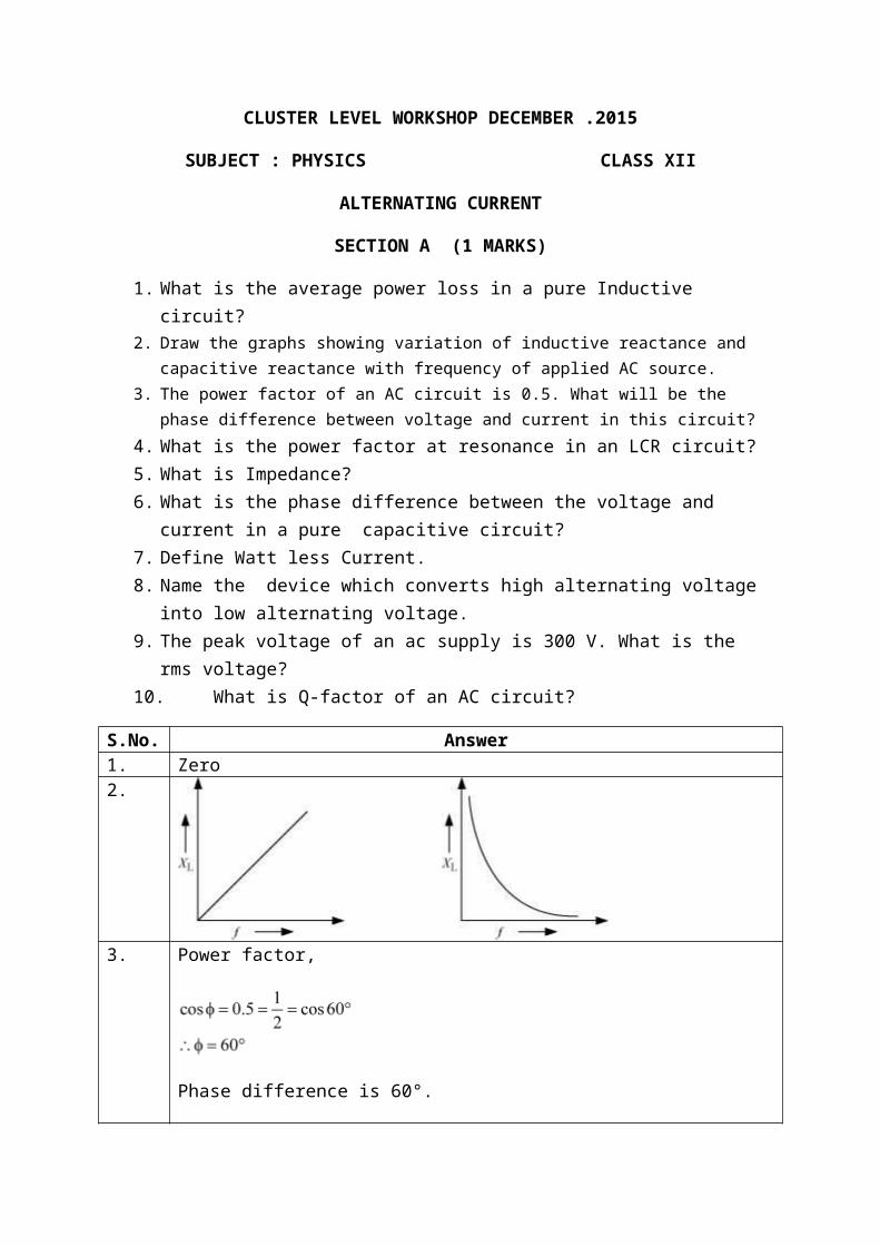
CLUSTER LEVEL WORKSHOP DECEMBER .2015 SUBJECT : PHYSICS CLASS XII ALTERNATING CURRENT SECTION A (1 MARKS) 1. What is the average power loss in a pure Inductive circuit? 2. Draw the graphs showing variation of inductive reactance and capacitive reactance with frequency of applied AC source. 3. The power factor of an AC circuit is 0.5. What will be the phase difference between voltage and current in this circuit? 4. What is the power factor at resonance in an LCR circuit? 5. What is Impedance? 6. What is the phase difference between the voltage and current in a pure capacitive circuit? 7. Define Watt less Current. 8. Name the device which converts high alternating voltage into low alternating voltage. 9. The peak voltage of an ac supply is 300 V. What is the rms voltage? 10. What is Q-factor of an AC circuit? S.No. Answer 1. Zero 2. 3. Power factor, Phase difference is 60°.
Transcript
CLUSTER LEVEL WORKSHOP DECEMBER .2015
SUBJECT : PHYSICS CLASS XII
ALTERNATING CURRENT
SECTION A (1 MARKS)
1. What is the average power loss in a pure Inductive circuit?2. Draw the graphs showing variation of inductive reactance and capacitive reactance with
frequency of applied AC source.3. The power factor of an AC circuit is 0.5. What will be the phase difference between voltage
and current in this circuit?4. What is the power factor at resonance in an LCR circuit?5. What is Impedance?6. What is the phase difference between the voltage and current in a pure capacitive
circuit?7. Define Watt less Current.8. Name the device which converts high alternating voltage into low alternating voltage. 9. The peak voltage of an ac supply is 300 V. What is the rms voltage?10. What is Q-factor of an AC circuit?
S.No. Answer1. Zero2.
3. Power factor,
Phase difference is 60°.
4. 15. It is the effective opposition to the flow of current provided by the Inductor,
Capacitor and resistor.6. 900 lagging behind7. It is the current passing in a pure capacitive or Inductive circuit in which the net
power loss is Zero.8. Step down Transfer
9. 300/(2)1/2= 212.23 volt10.
The ratio is called the quality factor or Q-factorOrIt can also be defined as the ratio of potential drop across either the inductor or the capacitor to the potential drop across the resistor.
SECTION B (2 MARKS)
1. A 100 Ω resistor is connected to a 220 V, 50 Hz ac supply. (a) What is the rms value of current in the circuit? (b) What is the net power consumed over a full cycle?
2. Calculate the average voltage in half cycle of an AC signal?3. What is resonance frequency? Find the expression for the resonance frequency.4. Draw the schematic diagram of a transformer. Distinguish between step up and step
down transformer.5. A coil of 0.01H inductance and 1 ohm resistance is connected to 200 volt, 50Hz ac
supply. Find the impedance of the circuit and phase difference of the circuit.
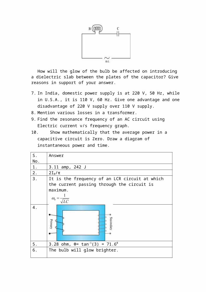
6. An electric bulb B and a parallel plate capacitor C are connected in series to the a.c. Mains as shown in the given figure. The bulb glows with some brightness.
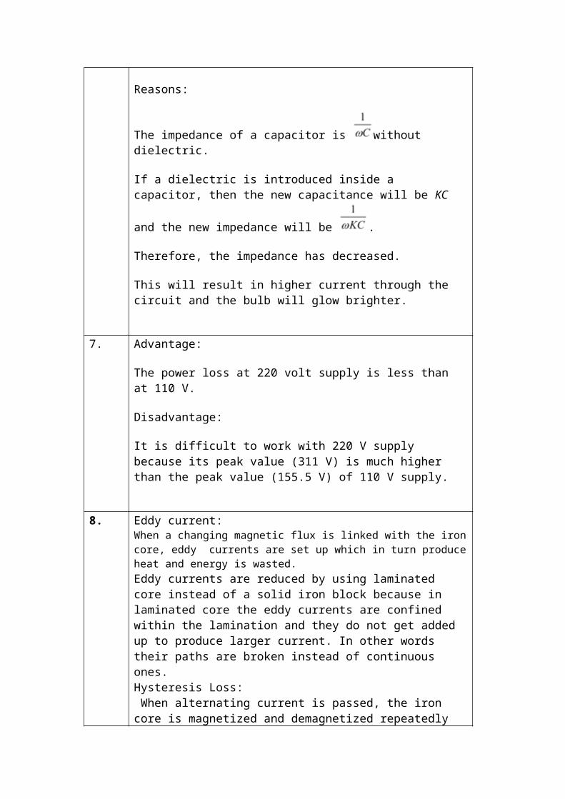
How will the glow of the bulb be affected on introducing a dielectric slab between the plates of the capacitor? Give reasons in support of your answer.
7. In India, domestic power supply is at 220 V, 50 Hz, while in U.S.A., it is 110 V, 60 Hz. Give one advantage and one disadvantage of 220 V supply over 110 V supply.
8. Mention various losses in a transformer.9. Find the resonance frequency of an AC circuit using Electric current v/s frequency
graph.10. Show mathematically that the average power in a capacitive circuit is Zero. Draw a
diagram of instantaneous power and time.
S. No. Answer1. 3.11 amp, 242 J2. 2I0/π3. It is the frequency of an LCR circuit at which the current passing
through the circuit is maximum.
4.
5. 3.28 ohm, Φ= tan-1(3) = 71.60
6. The bulb will glow brighter.
Reasons:
The impedance of a capacitor is without dielectric.
If a dielectric is introduced inside a capacitor, then the new capacitance
will be KC and the new impedance will be .
Therefore, the impedance has decreased.
This will result in higher current through the circuit and the bulb will glow brighter.
7. Advantage:
The power loss at 220 volt supply is less than at 110 V.
Disadvantage:
It is difficult to work with 220 V supply because its peak value (311 V) is much higher than the peak value (155.5 V) of 110 V supply.
8. Eddy current:When a changing magnetic flux is linked with the iron core, eddy currents are set up which in turn produce heat and energy is wasted.Eddy currents are reduced by using laminated core instead of a solid iron block because in laminated core the eddy currents are confined within the lamination and they do not get added up to produce larger current. In other words their paths are broken instead of continuous ones.Hysteresis Loss: When alternating current is passed, the iron core is magnetized and demagnetized repeatedly over the cycles and some energy is being lost
in the process.9.
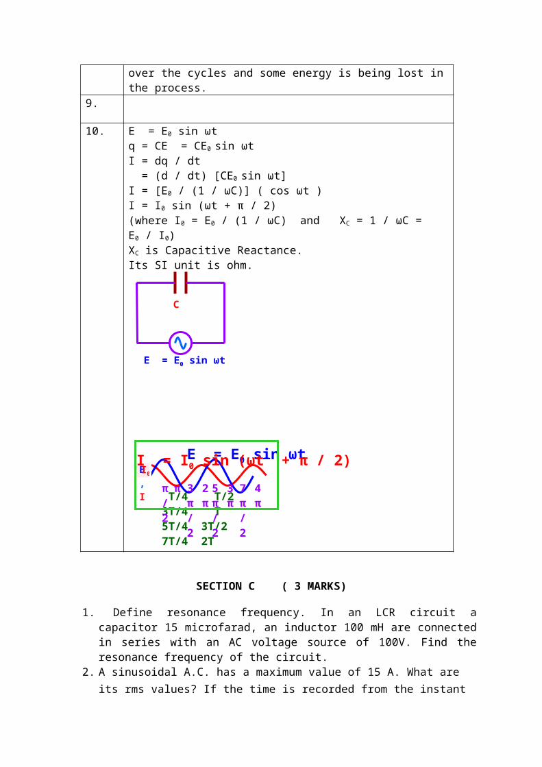
10. E = E0 sin ωtq = CE = CE0 sin ωt I = dq / dt = (d / dt) [CE0 sin ωt]I = [E0 / (1 / ωC)] ( cos ωt )I = I0 sin (ωt + π / 2)(where I0 = E0 / (1 / ωC) and XC = 1 / ωC = E0 / I0) XC is Capacitive Reactance. Its SI unit is ohm.
SECTION C ( 3 MARKS)
1. Define resonance frequency. In an LCR circuit a capacitor 15 microfarad, an inductor 100 mH are connected in series with an AC voltage source of 100V. Find the resonance frequency of the circuit.
2. A sinusoidal A.C. has a maximum value of 15 A. What are its rms values? If the time is recorded from the instant the current is zero and is becoming positive, what is the instantaneous value of the current after 1/300s given the frequency is 50 Hz.
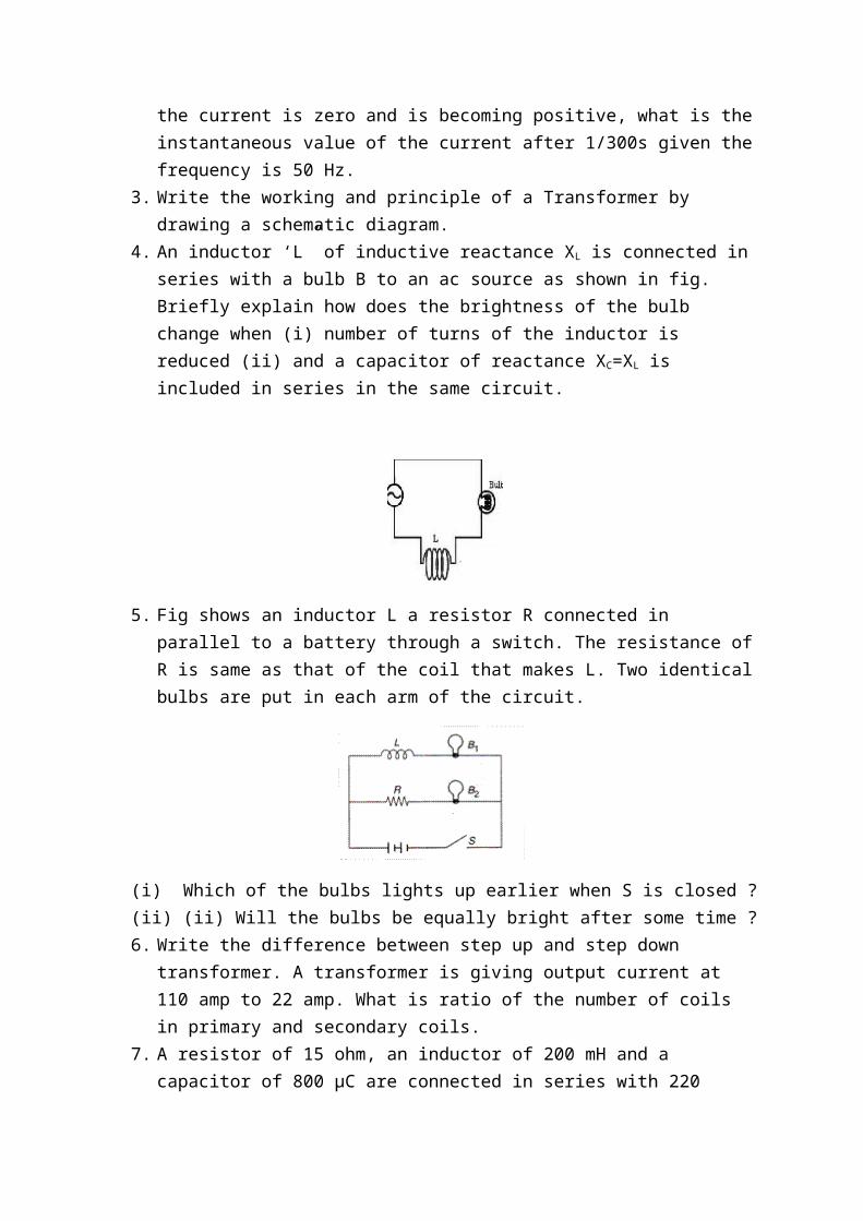
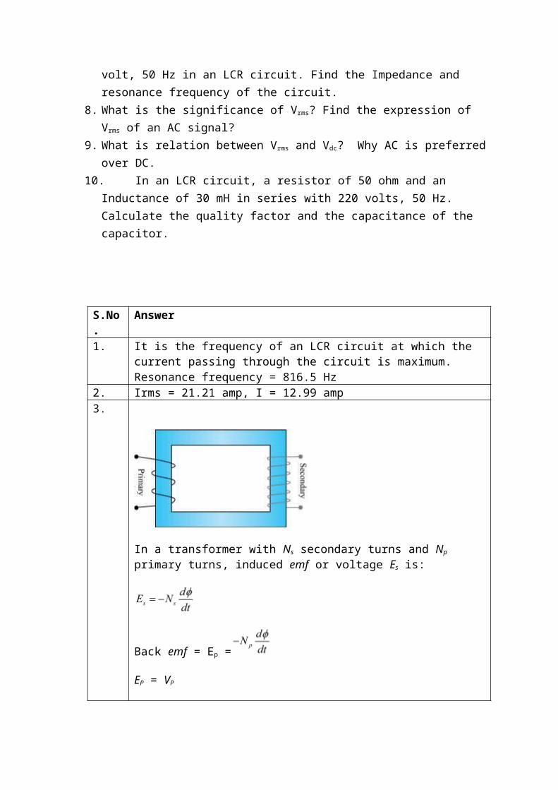
3. Write the working and principle of a Transformer by drawing a schematic diagram.4. An inductor ‘L” of inductive reactance XL is connected in series with a bulb B to an
ac source as shown in fig. Briefly explain how does the brightness of the bulb change when (i) number of turns of the inductor is reduced (ii) and a capacitor of reactance XC=XL is included in series in the same circuit.
E = E0 sin ωt
C
θ = ωt T/4 T/2 3T/4 T 5T/4 3T/2 7T/4 2T
π 2π
3π
4π
π/2
3π/2
5π/2
7π/2
E ,I I0
E = E0 sin ωtI = I0 sin (ωt + π / 2)
5. Fig shows an inductor L a resistor R connected in parallel to a battery through a switch. The resistance of R is same as that of the coil that makes L. Two identical bulbs are put in each arm of the circuit.
(i) Which of the bulbs lights up earlier when S is closed ?(ii) (ii) Will the bulbs be equally bright after some time ?6. Write the difference between step up and step down transformer. A transformer is
giving output current at 110 amp to 22 amp. What is ratio of the number of coils in primary and secondary coils.
7. A resistor of 15 ohm, an inductor of 200 mH and a capacitor of 800 μC are connected in series with 220 volt, 50 Hz in an LCR circuit. Find the Impedance and resonance frequency of the circuit.
8. What is the significance of Vrms? Find the expression of Vrms of an AC signal?9. What is relation between Vrms and Vdc? Why AC is preferred over DC.10. In an LCR circuit, a resistor of 50 ohm and an Inductance of 30 mH in series with 220
volts, 50 Hz. Calculate the quality factor and the capacitance of the capacitor.
S.No. Answer1. It is the frequency of an LCR circuit at which the current passing through the
circuit is maximum.Resonance frequency = 816.5 Hz
2. Irms = 21.21 amp, I = 12.99 amp3.
In a transformer with Ns secondary turns and Np primary turns, induced emf or voltage Es is:
Back emf = Ep =
EP = VP
Es = Vs
Thus, Vs = … (i)
Dividing equations (i) and (ii), we obtain
If the transformer is 100% efficient, then
Thus, combining the above equations,
If Ns > Np, then the transformer is said to be step-up transformer because the voltage is stepped up in the secondary coil.
No, the transformer does not violate the principal of conservation of energies. This can be easily observed by the following equation:
Power consumed in both the coils is the same as even if the voltage increases or current increases, their product at any instant remains the same.
4. (i) With the reduction in the number of turns of the coil, the inductive reactance XL will decrease and more current will flow through the bulb. The bulb glows brighter.
(ii) When XL= XC in the LCR series , the circuit behaves as a resistive circuit only so circuit current will increase and the bulb glows brighter.
5. (i) When switch is closed induced emf in inductor, called back emf delays the glowing of lampB1 so lamp B2 lights up earlier.
(ii) Yes. In this case at steady state inductive effect becomes meaningless so both bulbs become equally bright after some time.
6. 5 : 17. 25 ohm, 7.9 Hz8.
9. Vrms= Vdc.
Advantages:1. Production of AC is less expensive2. can be transmitted over a long distance without much a much power loss3. It can be easily rectified.
10. Q = 0.188, C= 33.8 μF
SECTION –E (5 MARKS)
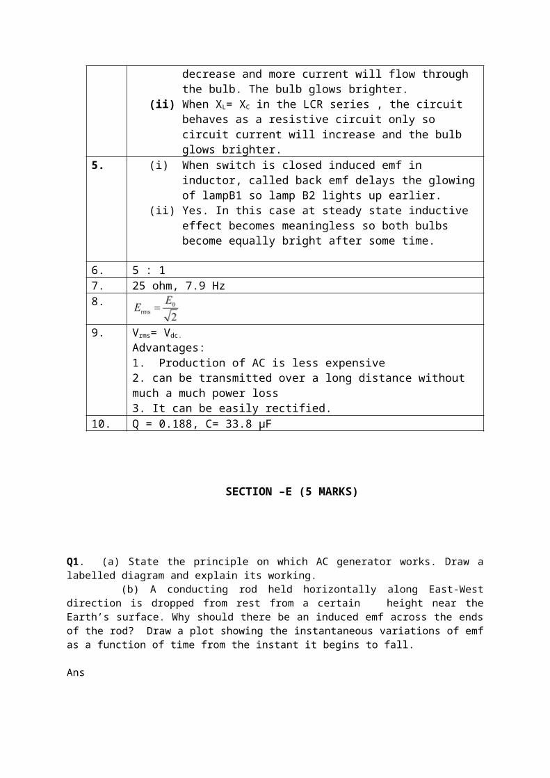
Q1. (a) State the principle on which AC generator works. Draw a labelled diagram and explain its working. (b) A conducting rod held horizontally along East-West direction is dropped from rest from a certain height near the Earth’s surface. Why should there be an induced emf across the ends of the rod? Draw a plot showing the instantaneous variations of emf as a function of time from the instant it begins to fall.
Ans (a Principle of AC generator- It works on the principle of electromagnetic induction.
In an A.C. generator, mechanical energy is converted to electrical energy by virtue of
electromagnetic induction.
* Rotation of rectangular coil in a magnetic field causes change in flux (Φ = NBACosωt).
* Change in flux induces emf in the coil which is given by
ε= -dΦ/dt = NBAωSinωt ε ε= ε0Sinωt
* Current induced in the coil I = ε/R = ε0Sinωt/R = I0Sinωt
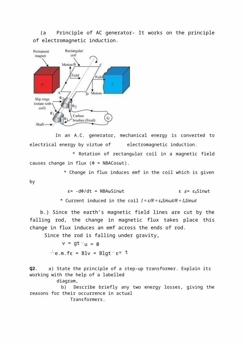
b.) Since the earth’s magnetic field lines are cut by the falling rod, the change in magnetic flux takes place this change in flux induces an emf across the ends of rod. Since the rod is falling under gravity, v = gt∵u = 0 e.m.fε = Blv = Blgt∴ε∝ tQ2. a) State the principle of a step-up transformer. Explain its working with the help of a labelled diagram, b) Describe briefly any two energy losses, giving the reasons for their occurrence in actual Transformers.
a Principle, It works on the principle of mutual induction.
In a transformer with Ns secondary turns and Np primary turns, induced emf or voltage Es is:
Back emf = Ep =
EP = VP
Es = Vs
Thus, Vs = … (i)
Dividing equations (i) and (ii), we obtain
If the transformer is 100% efficient, then
Thus, combining the above equations,
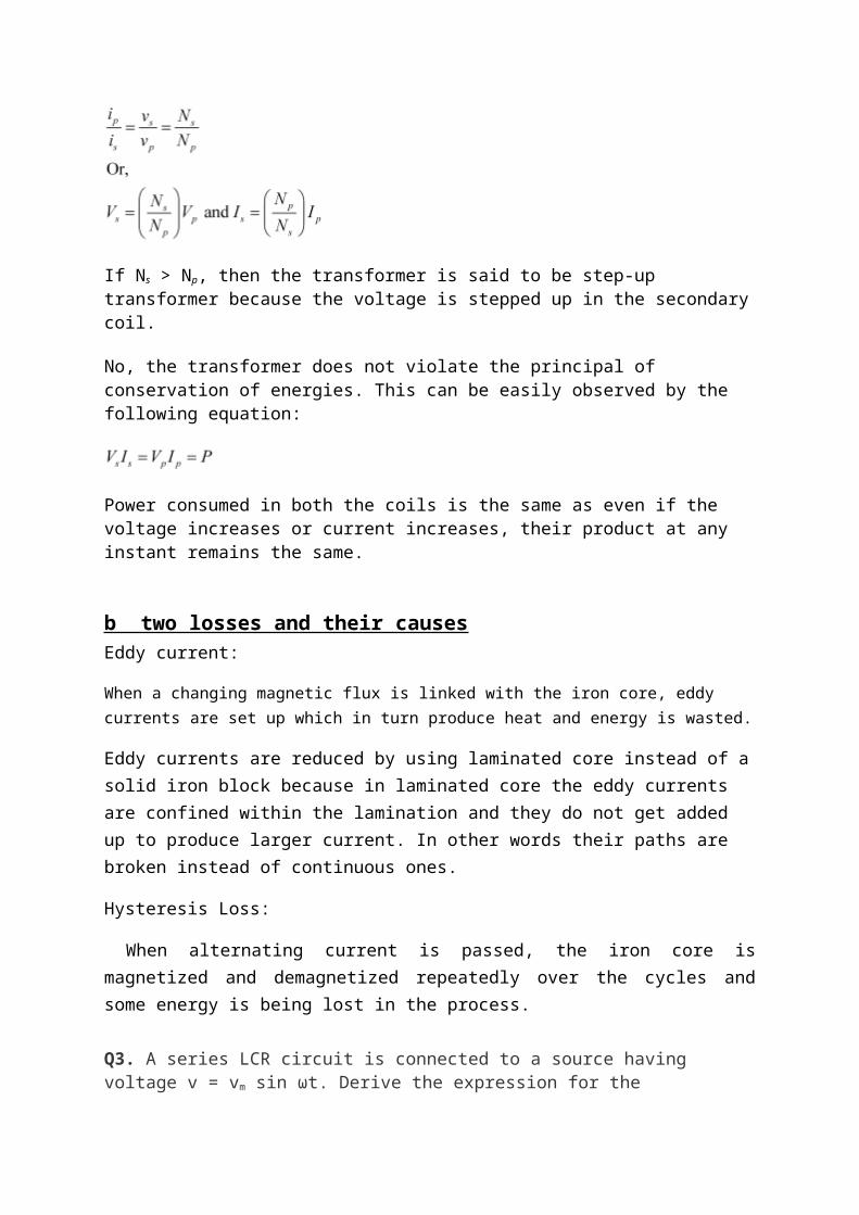
If Ns > Np, then the transformer is said to be step-up transformer because the voltage is stepped up in the secondary coil.
No, the transformer does not violate the principal of conservation of energies. This can be easily observed by the following equation:
Power consumed in both the coils is the same as even if the voltage increases or current increases, their product at any instant remains the same.
b two losses and their causesEddy current:
When a changing magnetic flux is linked with the iron core, eddy currents are set up which in turn produce heat and energy is wasted.
Eddy currents are reduced by using laminated core instead of a solid iron block because in laminated core the eddy currents are confined within the lamination and they do not get added up to produce larger current. In other words their paths are broken instead of continuous ones.
Hysteresis Loss:
When alternating current is passed, the iron core is magnetized and demagnetized repeatedly over the cycles and some energy is being lost in the process.
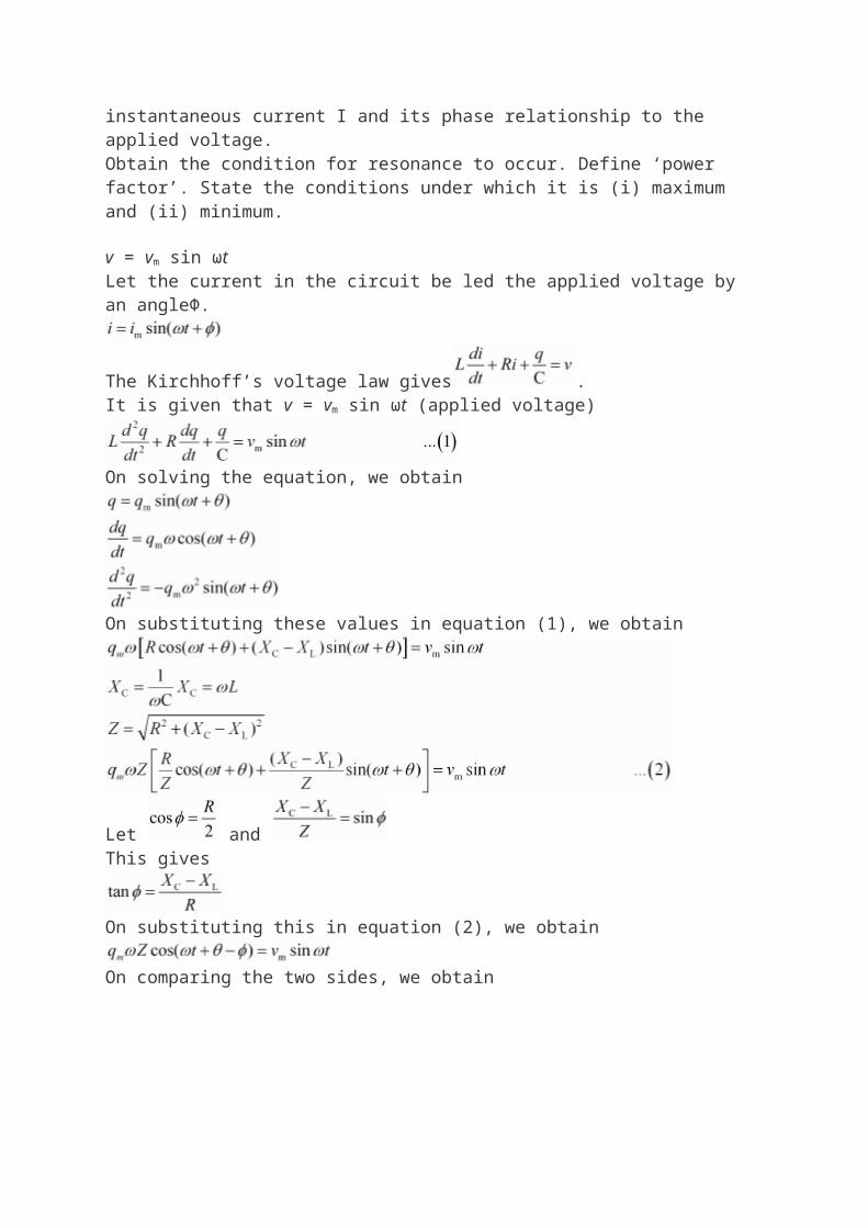
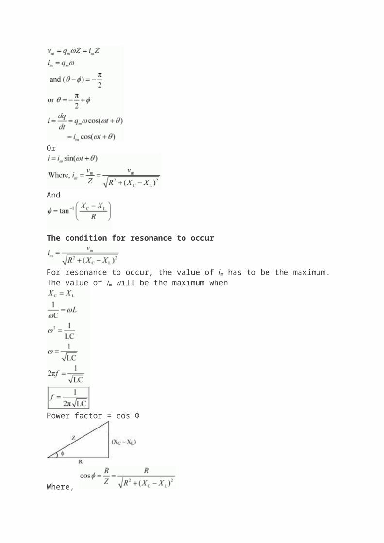
Q3. A series LCR circuit is connected to a source having voltage v = vm sin ωt. Derive the expression for the instantaneous current I and its phase relationship to the applied voltage.Obtain the condition for resonance to occur. Define ‘power factor’. State the conditions under which it is (i) maximum and (ii) minimum. v = vm sin ωtLet the current in the circuit be led the applied voltage by an angleΦ.
The Kirchhoff’s voltage law gives .It is given that v = vm sin ωt (applied voltage)
On solving the equation, we obtain
On substituting these values in equation (1), we obtain
Let and
This gives
On substituting this in equation (2), we obtain
On comparing the two sides, we obtain
Or
And
The condition for resonance to occur
For resonance to occur, the value of im has to be the maximum.The value of im will be the maximum when
Power factor = cos Φ
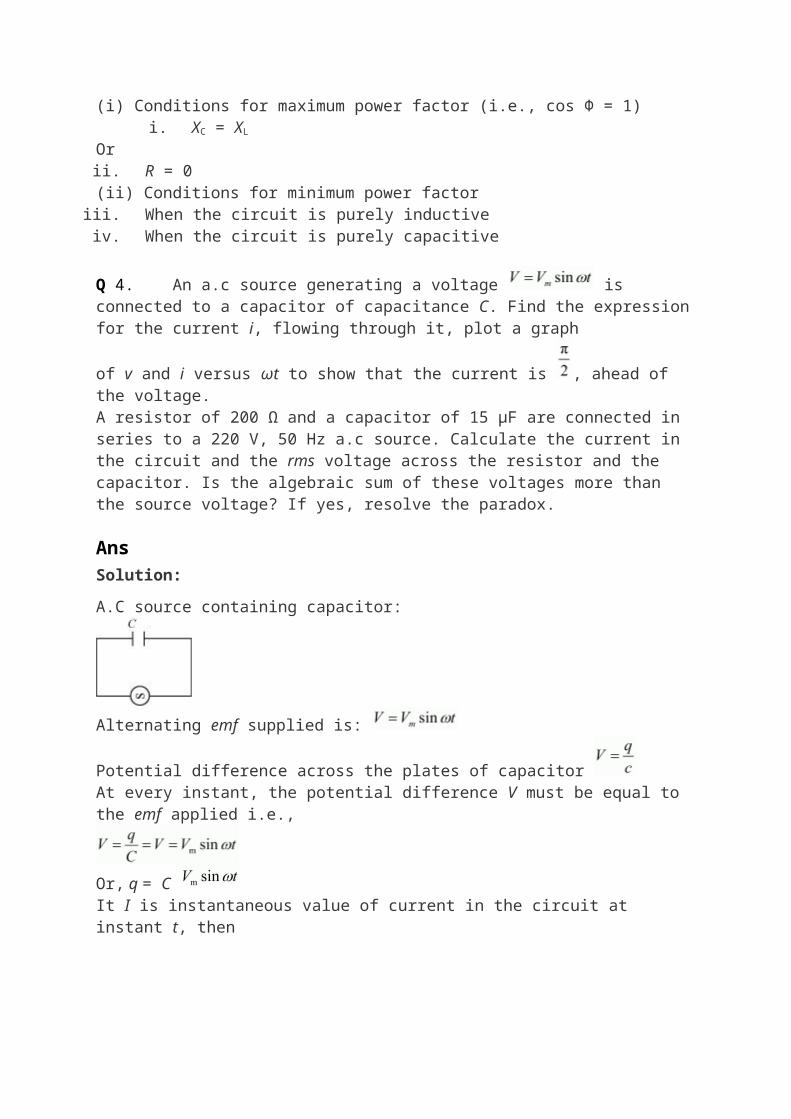
Where, (i) Conditions for maximum power factor (i.e., cos Φ = 1)
i. XC = XL
Orii. R = 0
(ii) Conditions for minimum power factoriii. When the circuit is purely inductiveiv. When the circuit is purely capacitive
Q 4. An a.c source generating a voltage is connected to a capacitor of capacitance C. Find the expression for the current i, flowing through it, plot a graph
of v and i versus ωt to show that the current is , ahead of the voltage.A resistor of 200 Ω and a capacitor of 15 μF are connected in series to a 220 V, 50 Hz a.c source. Calculate the current in the circuit and the rms voltage across the resistor and the capacitor. Is the algebraic sum of these voltages more than the source voltage? If yes, resolve the paradox.
AnsSolution:
A.C source containing capacitor:
Alternating emf supplied is:
Potential difference across the plates of capacitor At every instant, the potential difference V must be equal to the emf applied i.e.,
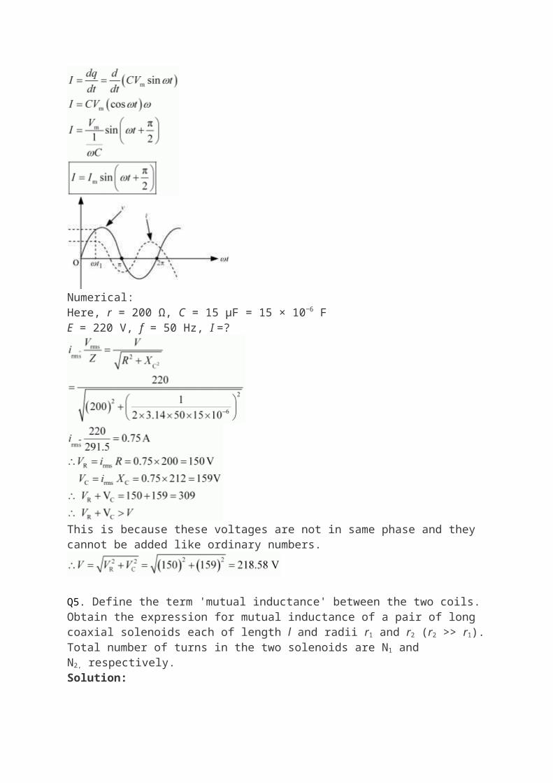
Or, q = C It I is instantaneous value of current in the circuit at instant t, then
Numerical:Here, r = 200 Ω, C = 15 μF = 15 × 10−6 FE = 220 V, f = 50 Hz, I =?
This is because these voltages are not in same phase and they cannot be added like ordinary numbers.
Q5. Define the term 'mutual inductance' between the two coils.Obtain the expression for mutual inductance of a pair of long coaxial solenoids each of length l and radii r1 and r2 (r2 >> r1). Total number of turns in the two solenoids are N1 and N2, respectively. Solution:
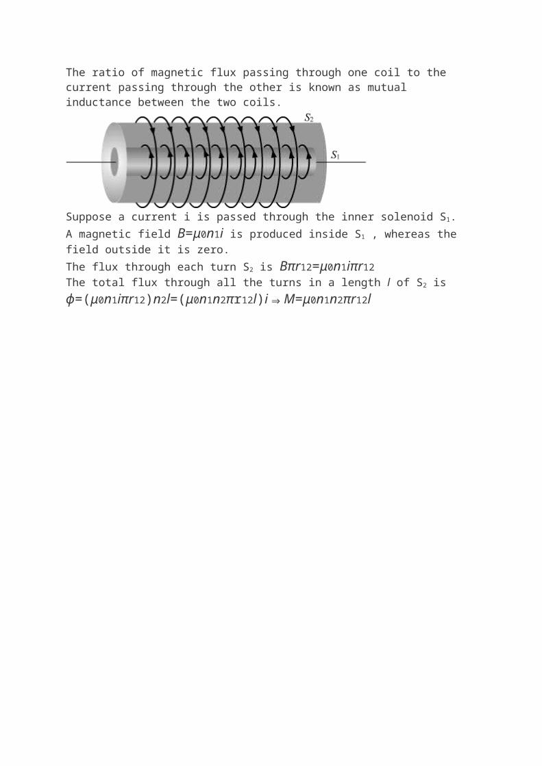
The ratio of magnetic flux passing through one coil to the current passing through the other is known as mutual inductance between the two coils.
Suppose a current i is passed through the inner solenoid S1.A magnetic field B=μ0n1i is produced inside S1 , whereas the field outside it is zero.The flux through each turn S2 is Bπr12=μ0n1iπr12The total flux through all the turns in a length l of S2 isϕ=(μ0n1iπr12)n2l=(μ0n1n2πr12l)i⇒M=μ0n1n2πr12l
ELECTROMAGNETIC INDUCTIONSECTION A (1 MARKS )
1.What is the basic cause of electromagnetic induction?Ans: Change in magnetic flux2. Does the change in magnetic flux induce emf or current?Ans: Induces emf , current is induced when circuit is closed.3. Induced emf is also called back emf? Why.Ans: It opposes any change in magnetic flux.4. A wire kept along the north-south direction is allowed to fall freely. Will an emf be induced in the wire ?
Ans: No because there is no change in the magnetic flux linked with the wire.5.Why the inductance coils are made of copper?Ans: Because copper has small resistance.6. A solenoid with an iron core and a bulb are connected to a d.c. source. How does the brightness of the bulb change when the iron core is removed from the solenoid?Ans: It will not change because of reactance of inductor is zero for d.c. source.
SECTION B ( 2 MARKS)1. Define self inductance. How does the self inductance of an coil change when an iron rod is introduced in it ?Ans: The magnetic flux linked with a coil when unit current is passed through it. The self inductance increases.2. Why is spark produced in the switch of a fan, when it is switched off?Ans: The break of circuit is sudden. A large induced emf set up across the gap of switch due to which sparking occurs. 3. State Faraday’s laws of electromagnetic induction.Ans Faraday’s first law: whenever there is change in the magnetic flux associated with a coil , an emf is induced in it.Faraday’s second law: The magnitude of emf induced is directly proportional to rate of change of magnetic flux4. State Lenz’s law.A coil of metal wire is held stationary in a non-uniform magnetic field. Is any emf induced in the coil?Ans: The emf induced opposes the cause that produces it. Yes, there will be an induced current in the coil.5. Define coefficient of mutual induction and give its SI unit.Ans: It is the magnetic flux linked with a coil when unit current is passed though the neighbouring coil.
SI unit of coefficient of mutual induction is Henry.
6. What are eddy currents? Mention any two useful application of eddy current.Ans: The current induced in a metallic sheet or plate when the magnetic flux linked with it changes.Applications: (i) In electric furnace to melt metal (ii) Dead beat galvanometer
7. Write three factors on which self inductance of a coil depend.Ans: (i) Number of turns (ii) Its area of cross-section (iii) The permeability of the core material
SECTION C (3 MARKS)1. A rectangular loop of area 20cm x 30cm is placed in a magnetic field of 0.3 T with its plane
(i) Normal to the field(ii) Inclined 300 to the field (iii) Parallel to the fieldFind flux linked with the coil in each case. Ans((i) 1.8 x 10⁻²wb,(ii) 0.9 x 10⁻²wb, (iii) zero)
2. Derive an expression for the induced emf in a conductor of length l, moving with a velocity v in a uniform magnetic field B.
A magnetic flux threading a coil changes from 12 x 10 -3 Wb to 6x10⁻³Wb in 0.01 sec. Calculate the induced emf.
E =dΦ/dt (0.6 v)
3. (a) Define self inductance. Write its S.I. units.(b) Derive an expression for self inductance of a long solenoid of length l, cross-sectional area A having N number of turns. Ans
(a) The phenomenon in which emf is induced in a single isolated coil due to change of flux through the coil by means of varying the current through the same coil is called self inductance. S.I unit of inductance is Henry.
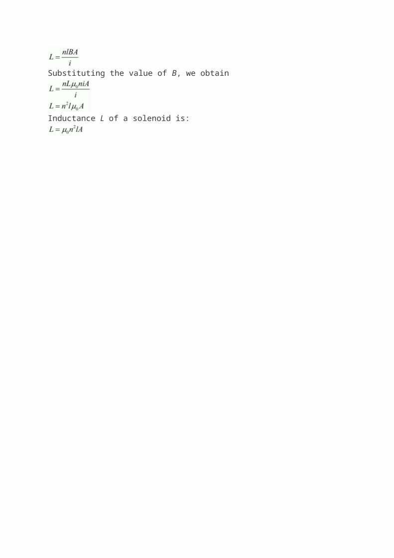
(b) Magnetic field B inside a solenoid carrying a current i is .
B =Let n be the number of turns per unit length.
Where,N is total number of turns
l is the length of the solenoid
Inductance, Substituting, we obtain
Substituting the value of B, we obtain
Inductance L of a solenoid is:
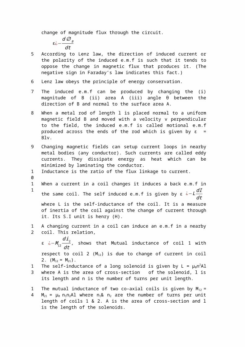
4. ELECTROMAGNETIC INDUCTION AND ALTERNATING CURRENTS
GIST1 The phenomenon in which electric current is generated by varying magnetic fields is
called electromagnetic induction.
2 Magnetic flux through a surface of area A placed in a uniform magnetic field B is defined as ΦB = B.A = BACosθ where θ is the angle between B and A.
3 Magnetic flux is a scalar quantity and its SI unit is weber (Wb). Its dimensional formula is [Φ] = ML2T-2A-1.
4 Faraday’s laws of induction states that the magnitude of the induced e.m.f in a circuit is equal to the time rate of change of magnitude flux through the circuit.
ε¿−d∅ B
dt5 According to Lenz law, the direction of induced current or the polarity of the induced
e.m.f is such that it tends to oppose the change in magnetic flux that produces it. (The negative sign in Faraday’s law indicates this fact.)
6 Lenz law obeys the principle of energy conservation.
7 The induced e.m.f can be produced by changing the (i) magnitude of B (ii) area A (iii) angle θ between the direction of B and normal to the surface area A.
8 When a metal rod of length l is placed normal to a uniform magnetic field B and moved with a velocity v perpendicular to the field, the induced e.m.f is called motional e.m.f produced across the ends of the rod which is given by ε = Blv.
9 Changing magnetic fields can setup current loops in nearby metal bodies (any conductor). Such currents are called eddy currents. They dissipate energy as heat which can be minimized by laminating the conductor.
10 Inductance is the ratio of the flux linkage to current.
11 When a current in a coil changes it induces a back e.m.f in the same coil. The self induced
e.m.f is given by ε ¿−L dIdt where L is the self-inductance of the coil. It is a measure of
inertia of the coil against the change of current through it. Its S.I unit is henry (H).
12 A changing current in a coil can induce an e.m.f in a nearby coil. This relation,
ε ¿−M 12
d i2
dt, shows that Mutual inductance of coil 1 with respect to coil 2 (M 12) is due
to change of current in coil 2. (M12 = M21).13 The self-inductance of a long solenoid is given by L = µ0n2Al where A is the area of cross-
section of the solenoid, l is its length and n is the number of turns per unit length.
14 The mutual inductance of two co-axial coils is given by M12 = M21 = µ0 n1n2Al where n1& n2
are the number of turns per unit length of coils 1 & 2. A is the area of cross-section and l is the length of the solenoids.
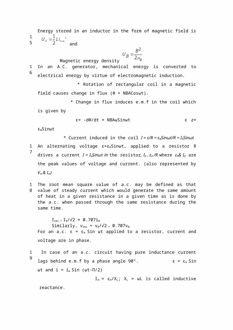
15 Energy stored in an inductor in the form of magnetic field is and
Magnetic energy density 16 In an A.C. generator, mechanical energy is converted to electrical energy by virtue of
electromagnetic induction.
* Rotation of rectangular coil in a magnetic field causes change in flux (Φ =
NBACosωt).
* Change in flux induces e.m.f in the coil which is given by
ε= -dΦ/dt = NBAωSinωt ε ε= ε0Sinωt
* Current induced in the coil I = ε/R = ε0Sinωt/R = I0Sinωt
17 An alternating voltage ε=ε0Sinωt, applied to a resistor R drives a current I = I0Sinωt in the
resistor, I0 = ε0 /R where ε0& I0 are the peak values of voltage and current. (also represented
by Vm & Im)
18 The root mean square value of a.c. may be defined as that value of steady current which would generate the same amount of heat in a given resistance in a given time as is done by the a.c. when passed through the same resistance during the same time.
Irms = I0/√2 = 0.707i0
Similarly, vrms = v0/√2 = 0.707v0.
For an a.c. ε = εm Sin ωt applied to a resistor, current and voltage are in phase.
19 In case of an a.c. circuit having pure inductance current lags behind e.m.f by a phase
angle 90°. ε = εm Sin ωt and i = im Sin (ωt-Π/2)
Im = εm/XL; XL = ωL is called inductive reactance.
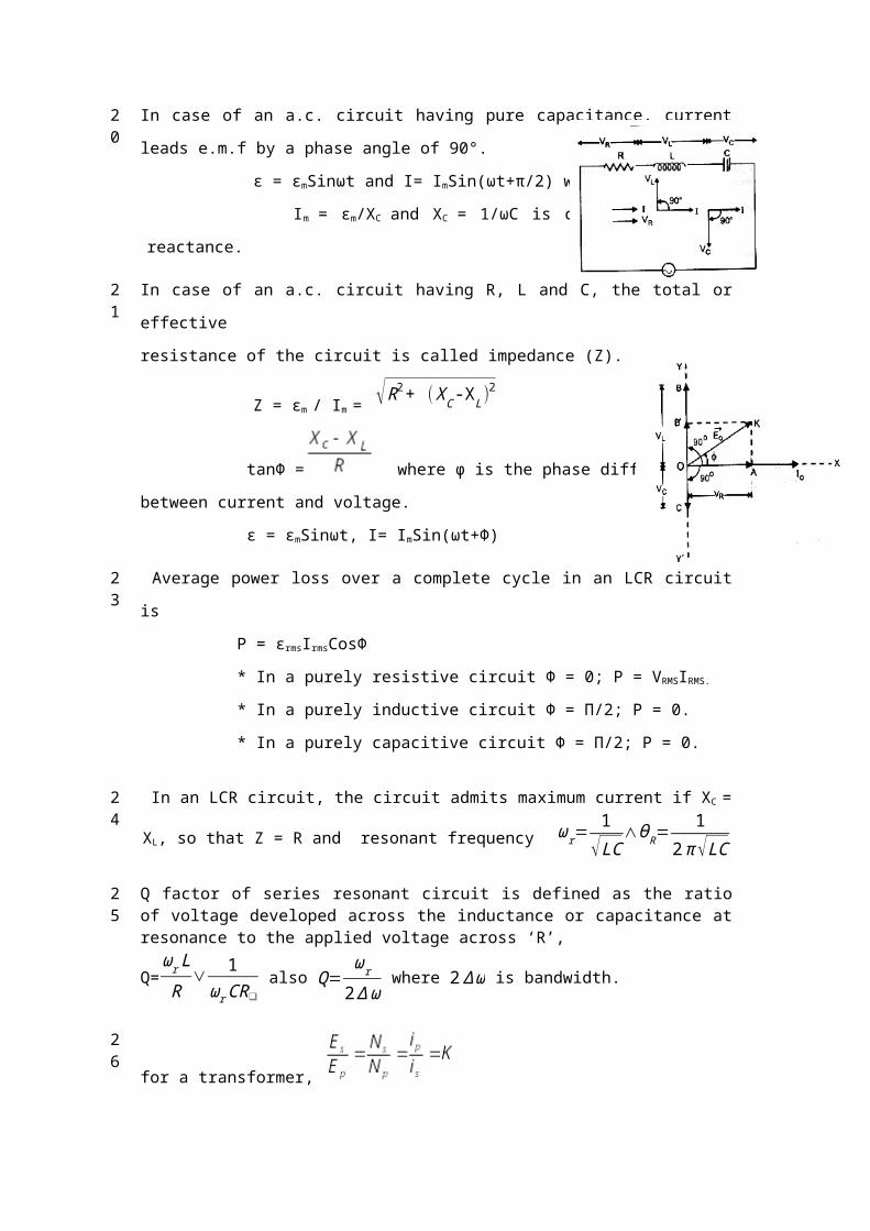
20 In case of an a.c. circuit having pure capacitance, current leads e.m.f by a phase angle of
90°.
ε = εmSinωt and I= ImSin(ωt+π/2) where
Im = εm/XC and XC = 1/ωC is called capacitive reactance.
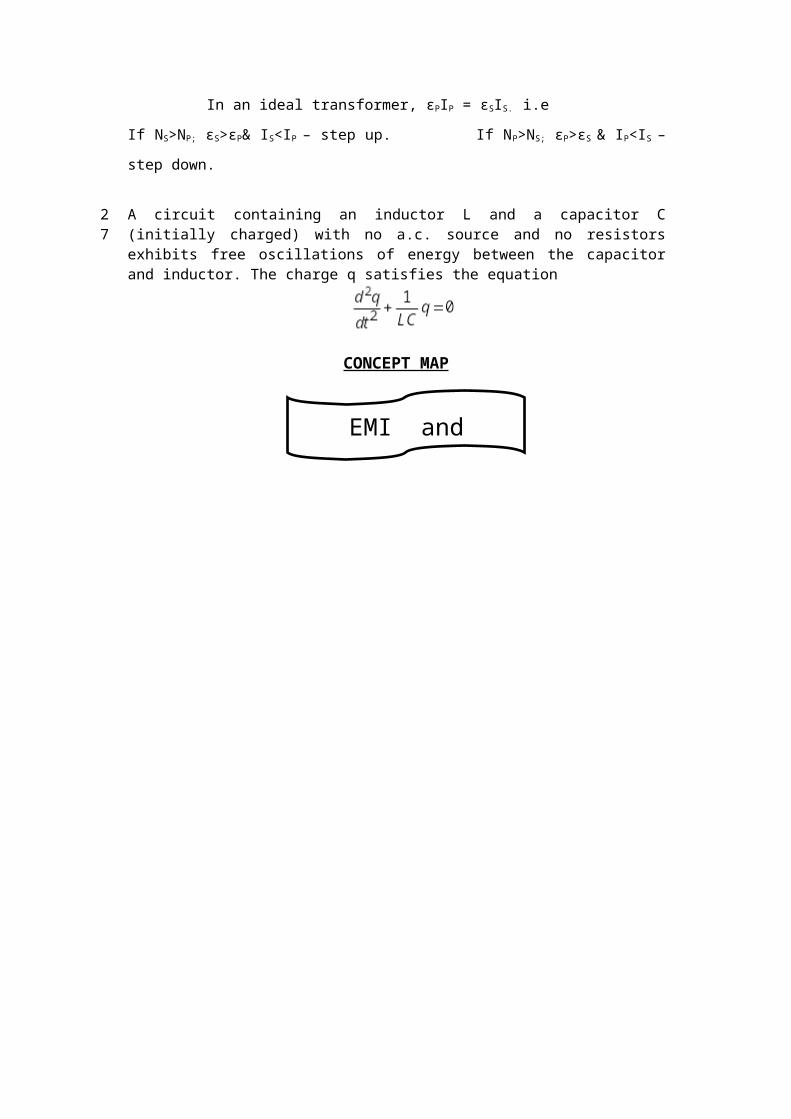
21 In case of an a.c. circuit having R, L and C, the total or effective
resistance of the circuit is called impedance (Z).
Z = εm / Im = √ R2+ ( XC -XL)2
tanΦ = where φ is the phase difference
between current and voltage.
ε = εmSinωt, I= ImSin(ωt+Φ)
23 Average power loss over a complete cycle in an LCR circuit is
P = εrmsIrmsCosΦ
* In a purely resistive circuit Φ = 0; P = VRMSIRMS.
* In a purely inductive circuit Φ = Π/2; P = 0.
* In a purely capacitive circuit Φ = Π/2; P = 0.
24 In an LCR circuit, the circuit admits maximum current if XC = XL, so that Z = R and resonant
frequency ωr=1
√ LC∧ϑ R=
12 π √LC
25 Q factor of series resonant circuit is defined as the ratio of voltage developed across the inductance or capacitance at resonance to the applied voltage across ‘R’,
Q=ωr L
R∨ 1
ωr CR❑ also Q=
ωr
2∆ ω where 2 ∆ ω is bandwidth.
26
for a transformer,
In an ideal transformer, εPIP = εSIS. i.e
If NS>NP; εS>εP& IS<IP – step up. If NP>NS; εP>εS & IP<IS – step down.
27 A circuit containing an inductor L and a capacitor C (initially charged) with no a.c. source
and no resistors exhibits free oscillations of energy between the capacitor and inductor. The charge q satisfies the equation
CONCEPT MAP
EMI and application
QUESTIONS
MAGNETIC FLUX, INDUCED E.M.F,
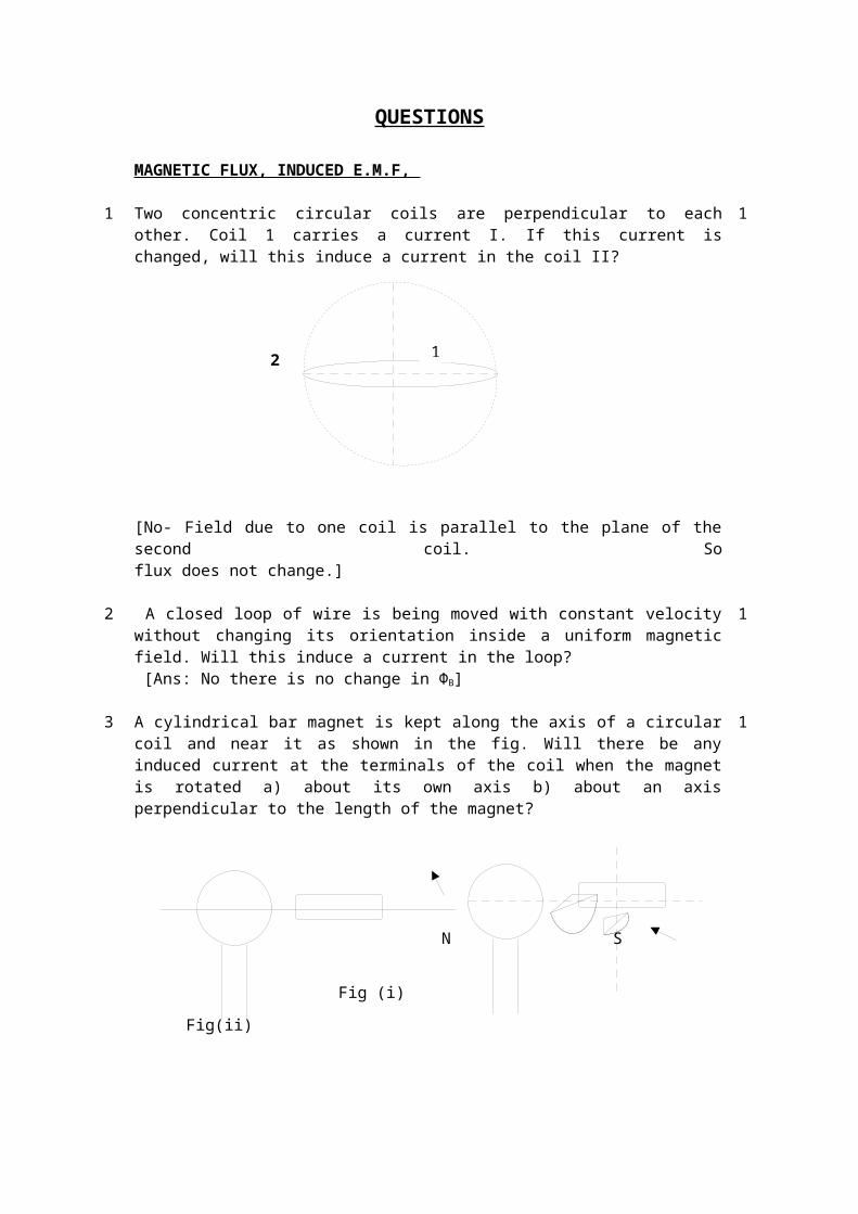
1 Two concentric circular coils are perpendicular to each other. Coil 1 carries a current I. If this current is changed, will this induce a current in the coil II?
[No- Field due to one coil is parallel to the plane of the second coil. So flux does not change.]
1
2 A closed loop of wire is being moved with constant velocity without changing its orientation inside a uniform magnetic field. Will this induce a current in the loop? [Ans: No there is no change in ΦB]
1
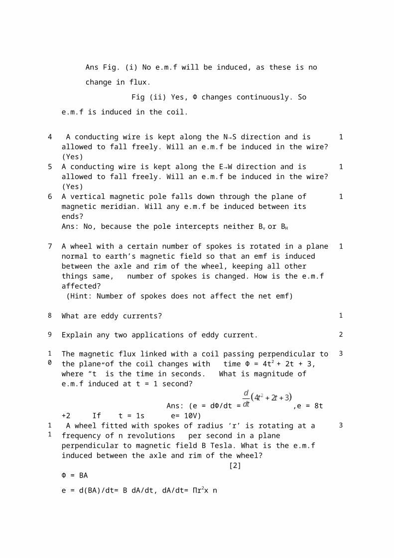
3 A cylindrical bar magnet is kept along the axis of a circular coil and near it as shown in the fig. Will there be any induced current at the terminals of the coil when the magnet is rotated a) about its own axis b) about an axis perpendicular to the length of the magnet?
N S
Fig (i) Fig(ii)
Ans Fig. (i) No e.m.f will be induced, as these is no change in flux.
Fig (ii) Yes, Φ changes continuously. So e.m.f is induced in the coil.
1
4 A conducting wire is kept along the N→S direction and is allowed to fall freely. Will an e.m.f be induced in the wire? (Yes)
1
5 A conducting wire is kept along the E→W direction and is allowed to fall freely. Will an e.m.f be induced in the wire? (Yes)
1
6 A vertical magnetic pole falls down through the plane of magnetic meridian. Will any e.m.f 1
2 1
S
be induced between its ends? Ans: No, because the pole intercepts neither Bv or BH
7 A wheel with a certain number of spokes is rotated in a plane normal to earth’s magnetic field so that an emf is induced between the axle and rim of the wheel, keeping all other things same, number of spokes is changed. How is the e.m.f affected? (Hint: Number of spokes does not affect the net emf)
1
8 What are eddy currents? 1
9 Explain any two applications of eddy current. 2
10
The magnetic flux linked with a coil passing perpendicular to the plane of the coil changes with time Φ = 4t2 + 2t + 3, where “t” is the time in seconds. What is magnitude of e.m.f induced at t = 1 second?
Ans: (e = dΦ/dt = ,e = 8t +2 If t = 1s e= 10V)
3
11
A wheel fitted with spokes of radius ‘r’ is rotating at a frequency of n revolutions per second in a plane perpendicular to magnetic field B Tesla. What is the e.m.f induced between the axle and rim of the wheel?
[2]Φ = BA
e = d(BA)/dt= B dA/dt, dA/dt= Πr2x n
e = B. Πr2n
3
12
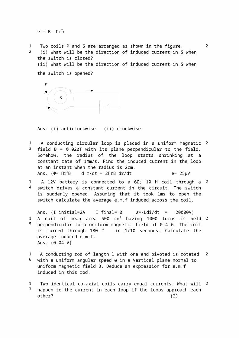
Two coils P and S are arranged as shown in the figure. (i) What will be the direction of induced current in S when the switch is closed?(ii) What will be the direction of induced current in S when the switch is opened?
Ans: (i) anticlockwise (ii) clockwise
2
13
A conducting circular loop is placed in a uniform magnetic field B = 0.020T with its plane perpendicular to the field. Somehow, the radius of the loop starts shrinking at a constant rate of 1mm/s. Find the induced current in the loop at an instant when the radius is 2cm. Ans. (Ф= Πr2B d Ф/dt = 2ΠrB dr/dt e= 25μV
2
14
A 12V battery is connected to a 6Ω; 10 H coil through a switch drives a constant current in the circuit. The switch is suddenly opened. Assuming that it took 1ms to open the switch calculate the average e.m.f induced across the coil.
Ans. (I initial=2A I final= 0 ε=-Ldi/dt = 20000V)
2
1 A coil of mean area 500 cm2 having 1000 turns is held perpendicular to a uniform magnetic 2
P
GN
S
A
B
5 field of 0.4 G. The coil is turned through 180 o in 1/10 seconds. Calculate the average induced e.m.f. Ans. (0.04 V)
16
A conducting rod of length l with one end pivoted is rotated with a uniform angular speed ω in a Vertical plane normal to uniform magnetic field B. Deduce an expression for e.m.f induced in this rod.
2
17
Two identical co-axial coils carry equal currents. What will happen to the current in each loop if the loops approach each other?
(2)
Ans. (Acc to Lenz’s law current in each coil will decrease)
2
18
Obtain the direction of induced current and e.m.f when the conductor AB is moved at right angles to a stationary magnetic field (i) in the upward direction (ii) in the downward direction. (i) B to A (ii) A to B)
2
19
A fan blade of length 0.5 m rotates perpendicular to a magnetic field of 5x10 -5 T. If the e.m.f induced between the centre and the end of the blade is 10 -2 V .Find the rate of rotation. Ans. (e=B dA/dt ; dt= 1/n ; n=254.7 rev/s)
3
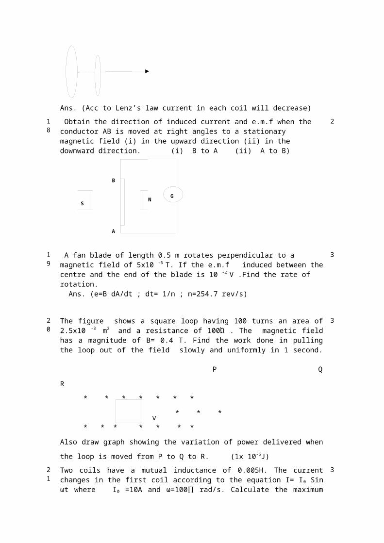
20
The figure shows a square loop having 100 turns an area of 2.5x10 -3 m2 and a resistance of 100Ώ . The magnetic field has a magnitude of B= 0.4 T. Find the work done in pulling the loop out of the field slowly and uniformly in 1 second.
P Q R
* * * * * * *
* * * * * *
* * * * * * *
Also draw graph showing the variation of power delivered when the loop is moved from P
to Q to R. (1x 10⁻⁶J)
3
v
Rr
21
Two coils have a mutual inductance of 0.005H. The current changes in the first coil according to the equation I= I0 Sin ωt where I0 =10A and ω=100∏ rad/s. Calculate the maximum value of e.m.f in the second coil. (5 π volts)
3
22
A long rectangular conducting loop of width L mass m and resistance R is placed partly above and partly below the dotted line with the lower edge parallel to it. With what velocity it should continue to fall without any acceleration?
* * * * * * * * *
* * * * * * * * *
-*--*--*----------*---*----
(mg = B2l2v/r ; v=mgr/ B2l2 )
3
INDUCTANCE1 Two conducting circular loops of radii R1 and R2 are placed in the same plane with their
centres coinciding. Find the mutual inductance between them assuming R2<< R1.
(M=µ0 πR22 /2R1)
2
2
Prove that the total inductance of two coils connected in parallel is
2
3 Two circular loops are placed with their centres at fixed distance apart. How would you orient the loops to have (i) maximum (ii) minimum Mutual inductance?
2
4 A coil of wire of certain radius has 600 turns and inductance of 108mH. What will be the inductance of another similar coil with 500 turns? (75mH)
2
5 Obtain the mutual inductance of a pair of coaxial circular coils kept separated by a
distance as shown in fig:-
2
ALTERNATING CURRENT - RMS CURRENT AND VOLTAGE
1 Find the RMS value of A.C shown in the figure. 1
2 The instantaneous value of e.m.f is given by ε= 300sin 314t. What is the rms value of
emf ?
Ans:- ε 0=300 units ε rms=212.1 units
1
3 Why a 220 V AC is considered to be more dangerous than 220 V DC?
Ans: peak value of AC is more than rms value which is equal to 311V.
1
4 An AC current flows through a circuit consisting of differerent elements connected in series.
(i) Is the applied instantaneous voltages equal to the algebraic sum of instantaneous voltages across the series elements of the circuit? (ii) Is it true for rms voltages?
Ans: (i) yes (ii) no
1
5 A capacitor blocks DC. Why?
Ans: XC=1/(2πfC ), for D.C f=0, therefore Xc=∞
1
6 What is the phase relationship between e.m.f across L and C in a series LCR circuit connected to an A.C source?
Ans:-The phase difference between VL and VC=1800
1
7 Two alternating currents are given by I1=I0Sinωt and I2= I0Sin(ωt+π/3). Will the rms valueofI1 & I2be equal or different?
Ans: The rms value will be equal.
1
8 An alternating current is given by i=i1Cosωt+i2Sin ωt. Find the rms current in the circuit.
(2)
Ans:√ ( i12+i1
2 )2
2
9 An alternating current having a peak value of 14A is used to heat a metal wire. What is the value of steady current which can produce the same heating effect as produced by AC? Why? Ans: irms=10A
2
10 If a constant current of 2.8A exists in a resistor, what is the rms value of current? Why? (2)
Ans: 2.8A
2
Z
11 Sketch a graph showing the variation of impedance of LCR circuit with the frequency of applied
voltage.
(1)
1
12 If resistance R in circuit ‘a’ be decreased, what will be the direction of induced current in
the circuit ‘b’.
2
AC CIRCUITS
1 What is meant by wattless current? 1
2 Define: Q factor in LCR series circuit 1
3 Why is choke coil preferred over resistor to reduce a.c? 1
4 How do R, XL and XC get affected when the frequency of applied AC is doubled?
Ans: a) R remains unaffected b) XL=2πfL, so doubled c) XC=1/2πfC, so halved
3
5 For circuits for transporting electric power, a low power factor implies large power loss in transmission line. Why?
(2)
Ans:
2
6 In an AC circuit there is no power consumption in an ideal inductor. Why? Ans: P= Vrms Irms Cos π/2 =0
2
7 An LCR series circuit is connected to an AC source. Which of its components dissipates power? L or C or R? Justify your answer.
Ans: Resistance, Power in L and C = 0
2
8 An electric lamp connected in series with a capacitor and an AC source is glowing with certain brightness. How does the brightness of the lamp change on reducing the capacitance?
2
ϑr ϑ
Ans: Brightness decreases. (As C decreases, XC increases. Hence Z increases and I
decreases.)
9 The power factor of an AC circuit is lagging by a factor 0.5. What does it mean? (2)
Ans: CosФ=0.5, ie, Ф =600. This implies that the current lags behind applied voltage by a phase angle of 600
2
10 The peak value of an AC is 5A and its frequency is 60Hz. Find its rms value. How long will the current take to reach the peak value starting from zero?Ans: Irms= 3.5A . Time period T=(1/60)s . The current takes one fourth of the time period to reach the peak value starting from zero. t =T/4 =(1/240)s.
2
11 The voltage and current in a series AC circuit are given by V= V 0 Cosωt & I= I0 Sinωt. What is the power dissipated in the circuit?
Ans:- I=I0Sinωt & V=V0Sin(ωt+π/2), since V leads current by a phase angle π/2, it is an inductive circuit . So, P=0
2
12 When an AC source is connected to a capacitor with a dielectric slab between its plates, will the rms current increase or decrease or remain constant?
Ans: The capacitance increases, decreasing the reactance Xc . Therefore the rms current increases.
2
13 Can peak voltage across an inductor be greater than the peak voltage supplied to an LCR?
Ans: Yes, at the time of break of a circuit, a large back e.m.f is set up across the circuit.
2
14 Write any two differences between impedance and reactance. 2
15 A 100 Ω resister is connected to 220V, 50 cycles per seconds. What is (i) peak potential difference (ii) average potential difference and (iii) rms current?
Ans. ε o=311.08V, εm =197.9V, Iv= 2.2 A
2
16 Define and derive the root mean square value of a.c voltage 3
RESONANCE in LCR Circuits
1 An inductor of inductance 100mH is connected in series with a resistance, a variable capacitance and an AC source of frequency 2 kHz. What should be the value of the capacitance so that maximum current may be drawn into the circuit?
Ans: 1/ωC=ωL ; C=1/ω2L=63nF.
2
2 In the circuit shown below R represents an electric bulb. If the frequency of the supply is doubled, how the valves of C and L should be changed so that the glow in the bulb remains unchanged?
2
Hint: XL=2πfL XC=1/2πfC
3 Draw phasor diagram for an LCR circuit for the cases (i) the voltage across the capacitor is greater than that across the inductor (ii) voltage across inductor is greater than that across the capacitor.
2
4 Does current in AC circuit lag, lead or remain in phase with voltage of frequency υ applied to a series LCR circuit when (i) υ = υ r
(ii) υ< υ r (iii) υ > υ r, where υ r resonant frequency?
1
5 11kw of electric power can be transmitted to a distant station at (i) 220V and (ii) 22kV. Which of the two modes of transmission should be preferred and why?
2
6 In an AC circuit V and I are given by V=100Sin100t volts and I= 100 Sin(100t+π/3)mA respectively. What is the power dissipated in the circuit?
Ans: V0=100V I0=100A Ф= π/3 P=Vrms Irms Cos Ф=2500W
2
7 The potential across a generator is 125V when it is suppling10A. When it supplies 30A, the potential is 120V. What is the resistance of the armature and induced e.m.f?
Ans: E=127.5V
2
8 In an LCR circuit the potential difference between terminals of inductance 60V, between terminals of capacitor 40V and between the terminals of resistor is 40V. Find the supply voltage. (3)Ans: In series LCR circuit voltage across capacitor and inductor are in opposite phase, so net voltage across the combination of L and C becomes 60-30=30V. Total voltage across R and L = 50V
3
9 The natural frequency of an LC circuit is 1,25,000 Hz. Then the capacitor C is replaced by another capacitor with a dielectric medium k, which decreases the frequency by 25 KHz. What is the value of k?
10 Obtain the resonant frequency and Q factor of a series LCR circuit with L= 3H, C= 27µF and R= 7.4 Ώ. Write two different ways to improve quality factor of a series LCR circuit
Ans: Q=45,ω0=111rad/s
3
11 An A.C source of voltage V= Vm Sinωt is connected one-by-one to three circuit elements X, Y and Z. It is observed that the current flowing in them
i. is in phase with applied voltage for Xii. Lags applied voltage in phase by π /2 for elements Y.
iii. Leads the applied voltage in phase by π /2 for element Z. Identify the three circuit elements.
5
TRANSFORMER
I
t
1 Why is the core of a transformer laminated? 1
2 Why can’t a transformer be used to step up dc voltages? 1
3 The graph below shows the variation of I with t. If it is given to the primary of a transformer, what is the nature of induced e.m.f in the secondary?
(Hint: e has constant positive value in the first part and a constant negative value in the
second part)
1. The turn ratio of a transformer is 10. What is the e.m.f in the secondary if 2V is supplied to primary?
2. A transformer has an efficiency of 80% It works at 4kW and 100V. If the secondary voltage Is240V find the primary current.
(40 A )
3
4 When a voltage of 120V is given to the primary of a transformer the current in the primary is 1.85mA. Find the voltage across the secondary when it gives a current of 150mA. The efficiency of the transformer is 95%
(1406V)
3
GENERATOR
1 If the speed of rotation of armature is increased twice how would it affect the (a) maximum e.m.f produced (b) frequency of the e.m.f?
(e=NBAω ;f=ω/2Π)
1
2 A coil of area 0.2m2 and 100 turns rotating at 50 revolutions per second with the axis perpendicular to the field. If the maximum e.m.f is 7kV determine the magnitude of magnetic field. (1.1 Tesla)
2
3 An ac generator consists of a coil of 50 turns and an area of 2.5m2 rotating at an angular speed of 60 rad/s in a uniform magnetic field of B= 0.3T between two fixed pole pieces. The resistance of the circuit including that of the coil is 500Ώ
(i) What is the maximum current drawn from the generator? (ii)What is the flux through the coil when current is zero?