234
VILLAGE OF GLENVIEW ENGINEERING STANDARDS MANUAL COMMUNITY DEVELOPMENT DEPARTMENT January 1, 2016

VILLAGE
OF
GLENVIEW
ENGINEERING STANDARDS MANUAL
COMMUNITY DEVELOPMENT DEPARTMENT
January 1, 2016


REVISED JANUARY 1, 2016
NOTES TO READER
These Engineering Standards have been rewritten to set forth the current technical aspects
governing development/redevelopment of land within the jurisdiction of the Village of
Glenview.
Engineering Standards are based on the knowledge and experience of staff from many
departments. The current version of standards are determined to be the most beneficial to the
Village of Glenview and may or may not be used as a standard in other municipalities or
government agencies. These standards are based on a commitment of excellence and desire
to make Glenview the best for all residential, commercial and business properties. Standards
are continually under review and revisions are made when deemed in the best interest of the
Village. Approvals are a formal process and no one shall proceed with any construction
without Village Engineering Management (VEM) approval (and other requirements that
apply) or by lack of receipt of disapproval by the VEM.
Please review the Conceptual, Preliminary and Final Engineering requirements prior to
submitting plans for review and approval.
Joseph P. Kenney, P.E. Shane E. Schneider, P.E.
Community Development Director
Village Engineer


TABLE OF CONTENTS
Page
LIST OF DEFINITIONS AND ABBREVIATIONS …............…………………….. 1
DESIGN REFERENCES ………………………………………..........……………… 7
SECTION I ………………………………………………….................……………… 11
Conceptual Engineering Plans
A. Definition 13
B. Required Submittals 13
SECTION II ……………………………………………………….......………………. 15
Preliminary Engineering Plans
A. Definition 17
B. Required Submittals 17
C. Phasing of Developments 18
D. School and Park Requirements 19
SECTION III ……………………………………………………........……………….. 21
Final Engineering Plans
A. Required Submittals 23
B. Engineering Certification 26
C. Drawing Requirements 26
D. Miscellaneous Requirements 34
SECTION IV ………………………………………………………..………………… 37
Design Standards
A. Site Grading 40
B. Soil Erosion Control 45
C. Water Distribution System 50
D. Sanitary Sewer System 64
E. Storm Sewer System 69
F. Stormwater Management 75
G. Streets and Other Site Improvements 85
H. Environmental Assessment 111
I. Easements 112
J. Variances 115


Page
SECTION V …………………………………………………………....……………… 117
Plats
A. Plan 119
B. Easements 119
C. Certificates 119
SECTION VI ………………………………………………………….………………. 127
Traffic Impact Report
A. Existing Conditions 129
B. Trip Generation and Assignment 129
C. Analyses and Recommendations 130
SECTION VII ……………………………………………………….....……………… 131
Guarantees, Required Fees, and Maintenance Bonds
A. Letter of Credit Method of Guarantee 134
B. Surety Bond Method of Guarantee 136
C. Cash Escrow Method of Guarantee 138
D. Required Fees 138
E. Maintenance Bonds 140
SECTION VIII ………………………………………………………..………………. 141
Project Inspection Procedures
A. Site Grading 143
B. Underground Utilities 144
C. Pavement 145
D. General Conditions 148
SECTION IX ………………………………………………………..………………… 151
Close-Out Requirements
SECTION X …………………………………………………………...………………. 157
Details
1
Definitions and
Abbreviations

2

3
ACRONYM’S, DEFINITIONS AND ABBREVIATIONS
AASHTO American Association of State Highway and Transportation
Officials
ABS Acrylonitrile-Butadiene-Styrene
AGC Association of General Contractors
ANSI American National Standards Institute
APPROVED Unless otherwise stated, materials, equipment or methods
accepted and approved by the Community Development
and/or Public Works Departments.
APPROVED EQUAL A manufactured product, or a method or procedure, having the
same characteristics and similar in degree or other standard of
comparison to that specified.
AS-BUILT PLANS Design plans checked in the field and revised to show actual
locations, elevations, and materials for constructed
improvements, including, but not limited to, pavement,
utilities, grading and detention/retention facilities.
ASTM American Society for Testing and Materials
AWWA American Water Works Association
BFE Base Flood Elevation. The highest water surface elevation of
the Base Flood; having a one (1) percent statistical probability
of being equaled of exceeded in a given year. The Base Flood
is also referred to as the one hundred (100) year flood.
BMP Best Management Practice
BUILDING PERMIT A written authorization issued by the Village of Glenview for
the construction, erection or alteration of a structure or
building.
CCFPD Cook County Forest Preserve District
CCDTH Cook County Department of Transportation and Highways
COMPENSATORY
STORAGE
An artificial excavation creating a volume of on-site
stormwater storage, at or above the Base Flood Elevation, to
accommodate the existing stormwater storage displaced by
4
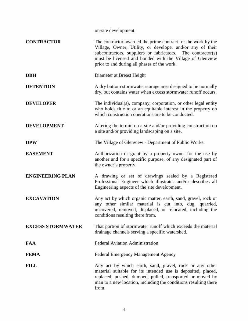
on-site development.
CONTRACTOR The contractor awarded the prime contract for the work by the
Village, Owner, Utility, or developer and/or any of their
subcontractors, suppliers or fabricators. The contractor(s)
must be licensed and bonded with the Village of Glenview
prior to and during all phases of the work.
DBH Diameter at Breast Height
DETENTION A dry bottom stormwater storage area designed to be normally
dry, but contains water when excess stormwater runoff occurs.
DEVELOPER The individual(s), company, corporation, or other legal entity
who holds title to or an equitable interest in the property on
which construction operations are to be conducted.
DEVELOPMENT Altering the terrain on a site and/or providing construction on
a site and/or providing landscaping on a site.
DPW The Village of Glenview - Department of Public Works.
EASEMENT Authorization or grant by a property owner for the use by
another and for a specific purpose, of any designated part of
the owner’s property.
ENGINEERING PLAN A drawing or set of drawings sealed by a Registered
Professional Engineer which illustrates and/or describes all
Engineering aspects of the site development.
EXCAVATION Any act by which organic matter, earth, sand, gravel, rock or
any other similar material is cut into, dug, quarried,
uncovered, removed, displaced, or relocated, including the
conditions resulting there from.
EXCESS STORMWATER That portion of stormwater runoff which exceeds the material
drainage channels serving a specific watershed.
FAA Federal Aviation Administration
FEMA Federal Emergency Management Agency
FILL Any act by which earth, sand, gravel, rock or any other
material suitable for its intended use is deposited, placed,
replaced, pushed, dumped, pulled, transported or moved by
man to a new location, including the conditions resulting there
from.

5
FIRM Federal Insurance Rate Map
GRADING The use of excavation or fill to bring the ground surface in
conformity with the site development plan.
IDOT Illinois Department of Transportation
IEPA Illinois Environmental Protection Agency
ISTHA Illinois State Toll Highway Authority
JULIE Joint Underground Locating Information for Excavators
MUTCD Manual of Uniform Traffic Control Devices published by the
United States Department of Transportation, Federal Highway
Administration, latest edition.
MWRD Metropolitan Water Reclamation District of Greater Chicago
NEMA National Electrical Manufacturer’s Association
NGVD National Geodetic Vertical Datum
NPDES National Pollution Discharge Elimination System
OWNER The individual(s) who holds title to or an equitable interest in
the property on which construction operations are to be
conducted.
PARCEL All contiguous land under one ownership.
PERMITTEE Any person to whom a site development permit is issued.
PROFESSIONAL
ENGINEER
A person licensed under the laws of the State of Illinois to
practice professional engineering.
PROJECT SITE A lot or parcel of land, or a contiguous combination thereof,
where the development is to be performed.
PROVIDE Furnish, install and connect.
RETENTION A wet bottom stormwater storage area designed to be
maintained as a pond or free water surface.
ROW Land owned, dedicated, or used as a public street or easement.

6
SEDIMENT Soil particles which become detached from the ground
surface, and are transported from their site of origin, and come
to rest on other ground surfaces or in bodies of water,
watercourses or wetlands.
SITE DEVELOPMENT
PERMIT
A permit issued by the Village of Glenview for site
development.
SITE DEVELOPMENT
PLAN
A drawing or other written description sealed by a Licensed
Architect or Licensed Professional Engineer that illustrates
and/or describes all aspects of the site development.
SOIL EROSION The detachment and movement of soil particles by water,
wind, ice and/or gravity.
STORMWATER RUNOFF Rainfall that is not absorbed or detained by soil or plant
material, or lost by evaporation.
SWPPP Stormwater Pollution Prevention Plan
TPO Village of Glenview - Tree Preservation Officer
USGS United States Coast and Geodetic Survey
VACANT Land on which there are no structures, or only structures
which are secondary to the use or maintenance of the land
itself.
VEM Village Engineering Management (includes Village Engineer,
Construction Division Engineer, Civil Engineer or
Engineering Project Manager).
VILLAGE The Village of Glenview
VILLAGE ENGINEER The Village Engineer or designate as defined in the Village
code
WMO Watershed Management Ordinance (MWRD Countywide
Ordinance)

7
Design References

8

9
DESIGN AND CONSTRUCTION REFERENCES
All work shall be designed and constructed in accordance with these Engineering Standards, as well
as the latest edition of the following references, as they apply:
A.
“Standard Specifications for Road and Bridge Construction”, Illinois
Department of Transportation (IDOT)
B. "Supplemental Specifications and Recurring Special Provisions and
Interim Special Provisions”, Illinois Department of Transportation
C. “Illinois Manual on Uniform Traffic Control Devices” and other
applicable supplements of the Illinois Department of Transportation
D. “Manual for Structural Design of Portland Cement Concrete
Pavement”, Illinois Department of Transportation
E. “Manual of Instructions for the Structural Design of Flexible
Pavements on Projects involving MFT, FAS and FAUS Funds”,
Illinois Department of Transportation
F. “Design Manual”, “Highway Manual”, “Culvert Manual”, Bridge
Manual” and other applicable manuals of the Illinois Department of
Transportation
G. “Standard Specifications for Water and Sewer Main Construction in
Illinois”, Standard Specifications Committee, comprised of IEPA,
IDOT, etc.
H. “Manual of Procedures” and “Sewer Permit Ordinance”,
Metropolitan Water Reclamation District of Greater Chicago
I. “Illinois Recommended Standards for Sewage Works”, Illinois
Environmental Protection Agency
J. Standards of the American Society for Testing and Materials
K. Standards of the American Association of State Highway and
Transportation Officials
L. Standard Specifications of the Illinois State Toll Highway Authority
M. Standards of the American Water Works Association
N. Standards of the American National Standards Institute, Inc.

10
O. Standards for erosion and sediment control complying with the
provisions of USEPA regulations, IEPA regulations, IDOT Erosion
Control/NPDES guidelines, per the “Illinois Urban Manual” prepared
by USDA, latest edition, and the Urban Soil Erosion and
Sedimentation Control in Illinois (latest edition) known as the “Green
Book”
P. Requirements of the State of Illinois Plumbing Code
Q. Village of Glenview Subdivision Code
R. Village of Glenview Zoning Ordinance
S. Village of Glenview Administrative Policies
Note: Alternate materials and/or construction methods shall be submitted in writing to the Village
Engineering and will be reviewed by the VEM and Public Works Department.

11
Section I
CONCEPTUAL ENGINEERING PLANS
A. Definition
B. Required Submittals

12

13
SECTION I
CONCEPTUAL ENGINEERING PLANS
A. DEFINITION
“Conceptual Engineering” plans and drawings are optional and should be submitted to the
Community Development Department for review prior to Preliminary Engineering and Site
Plan Review. Conceptual Engineering plans shall contain such information as is necessary, in
the judgment of the Village, to ensure that the general concept of the development is in
compliance with the Engineering Standards.
B. REQUIRED SUBMITTALS
If submitted, Conceptual Engineering plans and drawings shall include, but are not necessarily
limited to the following:
1. Four (4) sets of Concept Engineering drawings AND Preliminary Plats on twenty-four
(24) inches by thirty-six (36) inches sheets. Plans larger than 24 inches by 36 inches will
not be accepted or reviewed.
2. A digital submission of Adobe Acrobat (PDF) format files with to-scale sheet sizes of
twenty-four (24) inches by thirty-six (36) inches is preferred by the Village to the paper
format submittal.
3. All design elevations must reference the USGS National American Vertical Datum
(NAVD) of 1988 which supersedes the 1929 NGVD.
4. All horizontal coordinates must reference the Illinois East State Plane Coordinate System
North American Datum 1983.
5. Existing boundary survey.
6. Location Map, with the project site delineated thereon.
7. Proposed lot configuration and areas.
8. Width and location of existing and proposed right-of-way, street pavements, parking lots,
sidewalks, and bike paths.
9. Location and size of existing and proposed water, sanitary sewer and storm sewer systems,
sidewalks, and streets.
10. Location of any existing and proposed surface drainage systems and drainage patterns,
wetlands, flood plain and/or flood ways, etc.

14
11. Location of any existing and proposed detention/retention basin(s).
12. Location of any flood plain boundaries.
13. Areas designated for the passage and/or storage of surface run-off shall be identified and
their easements clearly delineated.
14. Tentative building footprint, top of foundation elevation(s), and proposed ground surface
elevations at key locations to show preliminary grading concepts.
15. All existing vegetation that is to be retained in place, including all trees ten (10) inches or
greater DBH.
16. Existing structures, wells, septic tanks and field tiles.
17. Tiered Flooding Boundaries and designations.
Note: Please consult the Design Standards, Section IV, before preparing any plans.

15
Section II
PRELIMINARY ENGINEERING PLANS
A. Definition
B. Required Submittals
C. Phasing of Developments
D. School and Park Requirements


17
SECTION II
PRELIMINARY ENGINEERING PLANS
A. DEFINITION
“Preliminary Engineering” shall contain such information as is necessary, in the judgment of
the VEM, to ensure that the proposed development can actually be constructed in accordance
with the Engineering Standards.
B. REQUIRED SUBMITTALS
Preliminary Engineering plans and drawings shall include, but are not necessarily limited to,
the following:
1. Four (4) sets of Preliminary Engineering drawings AND Preliminary Plats on twenty-four
(24) inches by thirty-six (36) inches sheets. Plans larger than 24 inches by 36 inches will
not be accepted or reviewed.
2. A digital submission of Adobe Acrobat (PDF) format files with to-scale sheet sizes of
twenty-four (24) inches by thirty-six (36) inches is preferred by the Village to the paper
format submittal.
3. All design elevations must reference the USGS National American Vertical Datum
(NAVD) of 1988 which supersedes the 1929 NGVD.
4. All horizontal coordinates must reference the Illinois East State Plane Coordinate System
North American Datum 1983.
5. Existing boundary survey.
6. Location Map, with the project site delineated thereon.
7. Proposed lot configuration and areas.
8. Width and location of existing and proposed right-of-way, street pavements, parking lots,
driveways, sidewalks, and bike paths.
9. Location and size of existing and proposed water, sanitary sewer and storm sewer systems
(including services), sidewalks, streets, and retaining walls.
10. Location of any existing and proposed surface drainage systems and drainage patterns,
upstream bypass areas, wetlands, flood plain and/or flood ways, etc.
11. Location of any existing and proposed detention/retention basin(s), and overflow routes.
18
12. Two (2) complete sets of stormwater detention calculations, together with a coded
drainage map of the development which shows the sub-drainage areas, pipe sizes, pipe
slope, and pipe flow calculations.
13. Location of all existing and proposed public utility, (i.e. electric, gas) easements,
covenants and other pertinent information.
14. A topographical map of existing conditions at one (l) foot contour intervals, including
adjacent property ground surface and top of foundation elevations.
15. Existing and proposed easements, including their widths and purpose.
16. Areas designated for the passage and/or storage of surface run-off shall be identified and
their easements clearly delineated.
17. Tentative building footprint, top of foundation elevation(s), and proposed ground surface
elevations at key locations to show preliminary grading concepts.
18. Letters of preliminary approval from other affected agencies, i.e. IDOT, CCHD,
Township, Sewer Districts, etc.
19. All existing vegetation that is to be retained in place, including all trees ten (10) inches or
greater DBH.
20. Existing structures, wells, septic tanks and field tiles.
21. Location of existing and proposed traffic signals, street and parking lot lights.
22. Location of existing and proposed parkway trees.
23. Location of flood plain boundaries.
24. Tiered Flooding Boundaries and designations
25. Description and elevation of Benchmark used.
26. Traffic Impact Report (if required).
NOTE: Please consult the Design Standards, Section IV, before preparing any plans.
C. PHASING OF DEVELOPMENTS
Preliminary Engineering must show planned improvements for the entire development. If the
project is to be phased, the phase limits shall be clearly denoted. Final Engineering plans for
portions of the development may be submitted in phases.

19
D. SCHOOL AND PARK DONATION REQUIREMENTS
Chapter 66 of the Municipal Code contains regulations regarding subdivisions (also referred
as the “Subdivision Code”). Article V, Division 2 of the Subdivision code contains
regulations regarding school and park donation requirements.
Refer to Sections 66-261 through 66-272 for requirements within The Glen. Refer to Division
Sections 66-291 through 66-305 for requirements outside The Glen.


21
Section III
FINAL ENGINEERING PLANS
A. Required Submittals
B. Engineering Certification
C. Drawing Requirements
D. Miscellaneous Requirements


23
SECTION III
FINAL ENGINEERING PLANS
The submittal for Final Engineering shall include, as a minimum, the following items:
A. REQUIRED SUBMITTALS:
1. Four (4) sets of Final Engineering drawings AND Final Plats on twenty-four (24) inches
by thirty-six (36) inches sheets. Plans larger than 24 inches by 36 inches will not be
accepted or reviewed.
2. A digital submission of Adobe Acrobat (PDF) format files with to-scale sheet sizes of
twenty-four (24) inches by thirty-six (36) inches is required for the final submittal.
3. All design elevations must reference the USGS National American Vertical Datum
(NAVD) of 1988 which supersedes the 1929 NGVD.
4. All horizontal coordinates must reference the Illinois East State Plane Coordinate System
North American Datum 1983.
5. Two (2) copies of the Environmental Assessment as a Condition of Land Conveyance,
Dedication or Donation, certified by an Illinois Registered Professional Engineer.
6. Two (2) copies of an Engineer's estimate showing the cost of all on and off-site
improvements associated with the development. This estimate may exclude buildings and
private landscaping.
a. Erosion control measures shall be listed by unit pay items to cover the installation
and repair with a contingency dollar amount for overall erosion control. Lump
sum erosion control pay items are not accepted as they do not sufficiently motivate
the contractor to properly maintain erosion control.
7. Copies of all signed contracts for the proposed site improvements.
6. The following permit applications and copies of approved permits must be received by the
VEM prior to Final Engineering Approval of a proposed project:
a. Four (4) copies for the Metropolitan Water Reclamation District of Greater Chicago
(MWRDGC).
b. Four (4) copies for the Cook County Department of Transportation and Highway
Department (CCDTH).
Permit for all work within CCDTH R.O.W.
c. Three (3) copies for the State of Illinois-Department of Transportation (IDOT).

24
Permit for all work within IDOT R.O.W.
Permit for all work within any flood way, as designated by the Illinois Department
of Natural Resources, Division of Water Resources.
d. Three (3) copies for the Illinois Environmental Protection Agency (IEPA).
Public Water Supply Construction Permit.
Public Sanitary Sewer Construction Permit.
National Pollutant Discharge Elimination System (NPDES) Permit No. ILR10 (see
NPDES permit process chart).
e. Sanitary Sewer Districts.
f. Townships (Niles, Maine, New Trier, Northfield).
g. North Cook County Soil and Water Conservation District.
h. U.S. Army Corp of Engineers – Wetlands.
i. Federal Aviation Administration (FAA).
j. Forest Preserve District of Cook County (FPDCC).
k. Illinois State Toll Highway Authority (ISTHA).
l. Various Railway Authorities.
m. Various miscellaneous authorities.
n. Federal Emergency Management Agency (FEMA).
7. Letter of permission to do off-site work on private property.
8. The Design Engineer is required to submit any plan changes required by another jurisdictional
agency under a cover letter explaining in detail the changes. Any failure to provide notice to
the VED is at the developer’s risk, which is likely to result in approval delays.

25
NPDES PERMIT PROCESS shall comply with the following: The following forms are required in
order to satisfy the erosion control requirements as outlined in the NPDES permit.
FORM(6) RESPONSIBILITY WHEN WHERE TO
SEND/FILE
Stormwater Pollution
Prevention Plan (SWPPP)
(1) and Erosion Control
Plan
Designer/Applicant’s Field
Engineer/Village
During Design Phase Submit it with plans
and keep on-site in
Project Files
• Copy to Village
Contractor Certification
Statement (2)
Contractor and all
Subcontractors whose
operations disturb soils (3)
Signed at or prior to
Preconstruction
Meeting
Form submitted with
plans and keep signed
form on-site in the
Project Files
• Copy to Village
Notice of Intent (NOI) Designer to prepare and
Permittee to sign (1)
30 days before
construction begins
and with Village
approval of SWPPP
and Erosion Plans (4)
Post at Jobsite
Original by Certified
Mail to IEPA
Copy to:
• Project on-site
File
• Copy to
Contractor
• Copy to Village
NPDES/Erosion Control
Inspection Report
Applicant’s Design
Engineer and Village
Inspector
Weekly and after
more than 0.5 in.
rainfall and 5.0 in. of
snowfall
Keep in Project on-
site File
• Copy to
Contractor
• Copy to Village
Incidence of Non-
Compliance (ION)
Applicant’s Design
Engineer or Village
Inspector
Within 5 days after
incident occurred Original by Certified
Mail to IEPA
Copy to:
• Project on-site
File
• Copy to
Contractor
• Copy to Village
Notice of Termination
(NOT)
Applicant’s Design
Engineer with Village
approval
Final Stabilization
(5)
Original by Certified
Mail to IEPA
Copy to:
• Project on-site
File
• Copy to Village
NOTES: (1) The Permittee or his assigned representative must sign this form.
(2) Field Engineer portion of the report should be completed before the actual
construction starts.
(3) Contractor and any sub-contractor whose operations will disturb soil will be required
to sign the Contractor Certification Statement.
(4) Thirty (30) days prior to start of construction, regardless if prior environmental
clearance has been received from all resource agencies.
(5) Final stabilization is defined as thorough establishment of an approved grass turf,
without bare spots (Note: this differs from IEPA regulation).
(6) Found in forms on IEPA web site www.epa.state.il.us/water.

26
B. ENGINEERING CERTIFICATION
Engineering plans, specifications and all calculations submitted for review must be signed and
sealed by a State of Illinois - Licensed Professional Engineer. Said attestation must include
the expiration date of the Professional Engineer's License and the date the seal was affixed.
C. DRAWING REQUIREMENTS
Complete drawings shall contain, at a minimum, the following:
1. To provide consistency from project to project, the plan sheets shall be assembled in the
sequence below. The designer should note that not all plans will have all sheets and some
sheets may be combined together (as approved by the VEM). All units shall be in English.
The required sequence is as follows:
a. Title Sheet
b. Index of Sheets
c. Alignment, Ties and Benchmarks
d. General Notes and Specifications
e. Summary of Quantities
f. Master Utility Plan
g. Plan and Profile Sheets
h. Drainage and Utility Sheets
i. Grading Plan (required) and Wetlands (if required)
j. Erosion Control Plan (required) and “SWPPP” (if required)
k. Intersections
l. Traffic Signals
m. Pavement Lighting
n. Pavement Markings and Signing
o. Traffic Control
p. Typical Sections
q. Details
r. “Cross Sections” (if required)

27
2. Title Sheet shall comply with the following:
a. Show title information in the top center of the sheet and include type of improvement.
Include below the title the Village provided project identification number such as “E
2005-075”.
b. Provide address, contact name and phone numbers for all utilities.
c. Provide a project layout map at bottom center of the sheet and include on the map the
location of project, north arrow, prominent features, route and street names, scale of
location map, township and range numbers.
d. Include the project approval block in the lower right-hand corner of the sheet and
check to ensure the signatures and dates for the VEM and Local jurisdictional officials,
where applicable.
e. Include the design firm’s company name, and the professional Engineer’s signature,
date of their license expiration and professional stamp below the client’s approval box.
f. Show the information for “JULIE”.
g. Include detailed plan legend.
3. Alignment, ties and benchmarks shall comply with the following:
a. Where necessary for complex projects, include a geometric alignment figure.
b. Show schematics for reference tie locations (when required) which include the
applicable centerline station, the applicable control ties, and the complete description
of the features used to determine the tie location.
c. All development, regardless of acreage or number of lots, shall provide information
within the Illinois East State Plane Coordinate System North American Datum 1983.
d. Provide the site benchmark data on this sheet and include an accurate description of
location, benchmark elevation, and coordinate information (if available). The site
benchmark shall be referenced to a Village datum benchmark (also described on
coversheet).
4. General notes and specifications shall include all applicable general plan notes and
specifications (design and construction notes should be project specific).
5. A summary of quantities sheet shall identify (as a minimum) all proposed public items
consistent with Section IX on a per block basis in a format approved by the VEM.
6. An overall master utility plan drawn to a minimum scale of one (1) inch equals one-
hundred (100) feet showing the following:

28
a. Existing and proposed right-of-way, street pavement, sidewalk, walkways, bikeways,
water or surface detention boundary limits, building footprint or pad limits, site
geometrics, and easements.
b. Size and location of existing and proposed utilities (storm sewer, sanitary sewer,
watermain, etc.).
c. On a separate sheet, show all utilities and services (including but not limited to gas,
electric, cable television, telephone, streetlights, traffic signals, watermain, sanitary
sewer and storm sewer), junction or controller boxes, pedestals and all easements,
right-of-way and lot lines. All wire services within exclusive detention easements
shall be placed in heavy-wall galvanized conduit.
d. Utility companies shall not be required to submit individual permit applications and
plans for items shown and approved on the overall utility plan. However, changes,
revisions or additions to the approved overall utility plan shall be submitted for review
and approval. Utility companies shall be responsible for notifying the Village a
minimum of forty-eight (48) hours prior to the commencement of work. All proposed
utilities shall conform to the following:
All proposed utilities, whether with the easements or future public right-of-way,
shall be placed a minimum of five (5) feet from the outside edge of any existing or
proposed Village watermain, sanitary or storm sewers, and other related
appurtenances.
All proposed utilities shall be placed a minimum of three (3) feet from any existing
or proposed back of curb and five (5) feet from the edge of an improved roadway
and are not within the clear zone.
All proposed utilities shall be placed within uniduct or other approved conduits,
under all existing or proposed Village maintained street crossings, at the
developer’s expense.
All proposed transformers, pedestals, switch gear boxes or other appurtenances to
proposed utilities shall not be placed within exclusive easements or in such a
manner so as to block swales, overland flow routes or access to proposed Village
maintained infrastructure. In addition, all appurtenances to proposed utilities shall
be constructed to the approved final grade.
e. Include a pipe and structure schedule.
7. Plan and Profile sheets shall comply with the following:
a. Plan and Profile views shall label the applicable plan view stations in the title block at
the lower right-hand corner on each sheet.

29
b. Plan View shall show mainline stationing increasing from left to right (south to north
or west to east). Provide tic marks along the centerline at fifty (50) foot intervals and
note the station on every even one-hundred (100) foot intervals and at all intersections.
Use a minimum scale of one (1) inch equals forty (40) feet. Show all P.C.’s and P.T.’s
along the centerline. Note all pavement widths at stations wherever there is a change
in pavement width. Provide a North arrow on each sheet. For temporary and
permanent entrances and side road intersections, show the facility with the applicable
street name, entrance type, the existing surface material type, the width of the
intersecting facility, and for intersections with public roads, the angle of intersection
from the side road centerline to the mainline centerline.
c. Profile View shall show the profile of the finished roadway centerline surface, bottom
of subgrade, top and bottom of underground utilities. The vertical scale shall be one
(1) inch equals five (5) feet. Show the existing ground line to the nearest 0.1′ and
proposed pavement surfaces to the nearest 0.01′. Show the vertical curve data above
the profile line for crest curves and below the profile line for sag curves including the
VPI station, the vertical curve length, the elevation at the VPI, and station and
elevation of high and low points of vertical curve. Show tangent grades to the nearest
hundredth (i.e., 0.01) of a percent. Use a “+” prefix for positive grades and “-” prefix
for negative grades. Show the elevations for the proposed centerline every fifty (50)
feet. Provide additional profiles, where required by the VEM for pavement edges,
ditches, right-of-way elevations or other situations. Note ditch locations with invert
elevations at fifty (50) foot intervals and breaks in grade on the cross sections and
include the gradient percentage, centerline station, beginning and ending elevations,
and elevations at gradient changes. Note all overhead utilities where they cross the
centerline and the type of utility. For bridges within the project, show elevations of
abutments, piers, low vertical clearance points, normal water level, high water lever,
and stream bed.
d. For utilities include the distance from the centerline, material type, pipe size, length
and slope, flow direction, upstream and downstream flow elevations, end section or
headwall type and size, and end treatment (rip rap). For manholes, catch basins, and
inlets, show the structure number, centerline station and offset, rim elevation, or grate
elevation at edge of pavement, and invert elevations and direction (N, S, E, W) for all
pipes. Show the areas of trench backfill under pavements, walks, driveways and
entrances.
8. An overall grading plan drawn to a minimum scale of one (l) inch equals one-hundred
(100) feet showing the following:
a. Existing and proposed right-of-way, pavement, and easements.
b. Existing and proposed drainage structures, including rim and invert elevations.
c. Existing and proposed contours by means of a topographic survey of the development
at one (1) foot contour intervals and such land beyond the development that may
impact or be impacted by the drainage and design elevations of the development. This
topographical survey is to be done using USGS 1988 NAVD. Surveys shall extend at
30
least fifty (50) feet off site in every direction, or to such further point or points as
determined to be required by the VEM.
d. Existing and proposed lot layout with lot numbers, site geometrics, foundation
elevations, exact locations of existing buildings adjacent to the development property
or subdivision, and key spot elevations to delineate overland stormwater flow.
e. Existing and proposed detention areas and overland flow routing. Include the existing
volume, normal water level, one-hundred (100) year HWL, overflow elevation, and the
proposed one-hundred (100) year HWL, design HWL, required volume, design
volume and overflow elevation.
f. Identification of existing and proposed streams, flood water run-off channels, basins,
ponds, wetlands, etc.
g. Tiered Flooding Boundaries and designations
h.
9. An overall erosion control plan drawn to a minimum scale of one (1) inch equals one-
hundred (100) feet showing the following:
a. Existing and proposed right-of-way, pavement, and easements.
b. Existing and proposed drainage structures, including only pertinent rim and invert
elevations.
c. Existing and proposed contours at one (1) foot intervals.
d. Existing and proposed foundation elevations and key spot elevations to delineate
overland stormwater flow.
e. Existing and proposed detention areas with high water elevation and overland flow
routing.
f. For those projects that disturb one (1) acre or more, include a stormwater pollution
prevention plan (SWPPP) on the overall erosion control plan which includes the
following:
Site description identifying potential sources (nature of construction activity) of
pollution that may affect the quality of stormwater discharges.
Intended sequence of major activities which disturb soils for major portions of the
site (e.g., grubbing, evacuation, grading).
Total site area and total site area to be disturbed by excavation, grading or other
activities.

31
Appropriate best management practices (BMP), including erosion, sediment, and
stormwater management controls to minimize the discharge of pollutants from the
site.
Description of steps to be taken to prevent and control pollutants in stormwater
discharge from the site, including inspection by the Design Engineer (Illinois
Licensed Professional Engineer) of all disturbed, unstabilized areas and
maintenance of all controls to ensure their effective operation.
10. Intersections shall include pavement elevations, lane widths, curb or edge of pavement
radii, curb ramps, turning radii for left turning vehicles, location of median noses and
islands, location of traffic signal equipment, location of traffic signs, pavement markings
and construction joint layout (if concrete).
11. Traffic Signals shall comply with the following:
a. Traffic signals shall be in accordance with the Illinois Department of Transportation
District I Traffic Signal Design Guideline.
b. North arrow up or to the right, and use layout scale of one (1) inch equals twenty (20)
feet. Break lines are not allowed. All pavement, driveways and cross streets between
the intersection and perimeter loops must be shown. Proposed geometrics only should
be shown. Label and dimension R.O.W. Dimension pavement marking and lane
widths. Provide IDOT District I traffic signal legend. Label roadway names.
Dimension equipment locations, pavement loops and their locations. Dimension and
size conduit runs. Show curb, sidewalk, known utilities, driveways, buildings and
other features adjacent to R.O.W., etc. and locate drainage structure(s) which may
affect signal appurtenances.
c. All lights shall be LED. Battery backup may be required as determined by the VEM.
d. Include phase designation diagram or chart sequence of operation. If these diagrams
or chart sequences do not fit on this sheet, a separate sheet may be used. Also include
diagram or chart sequence for emergency vehicle preemption and chart sequence for
railroad preemption.
e. Denote limits of interconnect system within intersections and system loops, and the
location of the master controller and telephone service.
f. Use IDOT District I notes for temporary traffic signals. Denote existing and proposed
geometrics. Include dimensional pole locations, sequence of operation, and locations
of existing equipment. Show schedule of existing equipment to be removed, salvaged
or returned, with note concerning who will receive equipment. Include notes
concerning any controller specifications, and temporary maintenance of interconnects.
12. Pavement lighting shall comply with the following:

32
a. Use Illinois Department of Transportation District I “General Guidelines for Lighting
Design and Plan Preparation” for any portion adjacent to IDOT facility.
b. Show base lighting layout with locations of light poles, control installation, conduits,
cables, light pole setback, and type of pole, breakaway or non-breakaway.
c. Submit calculations and supporting documentation showing the levels of luminance,
luminance and veiling luminance and uniformity ratios, voltage drop calculations,
cable sizing, load tabulations for each circuit, and grounding scheme.
d. Lighting for Village facilities shall meet with VEM approval.
13. Pavement markings and signings shall comply with the following:
a. Show existing and proposed sign locations with sheeting, post, base type, sign
dimensions, and station/offset location.
b. Show existing and proposed pavement markings with material, dimensions,
station/offset locations, taper rates, and lane widths. Pavement markings shall be in
accordance with IDOT District I Standards for Typical Pavement Marking.
14. Traffic Control shall comply with the following:
a. Where necessary, provide plan view sheets showing temporary widths and tapers,
temporary traffic lanes, proposed construction staging, location of signing for work
zones, temporary pavement markings (types and sizes), roadside safety and layouts,
and general notes for construction, closures, time frames, etc.
b. Utilize and reference IDOT Traffic Control Devices Standard.
15. Typical sections shall comply with the following:
a. Ensure that all applicable typical sections are provided with horizontal dimensions,
vertical dimensions, type and depths of surface, base, and sub-base courses, curb and
gutters/medians, landscaping, side slopes expressed as a ratio of vertical to horizontal
distances, cross slopes expressed in percent, and all other applicable notations.
b. Include all notes applicable to the typical sections.
c. Include the pavement design assumptions and computations.
16. Details shall comply with the following:
a. Include applicable Village details.
b. Include all applicable IDOT Highway Standards necessary to construct the project.
17. Cross sections shall comply with the following:

33
a. Plot cross sections at intervals or locations as directed by the VEM. Use a horizontal
scale of one (1) inch equals ten (10) feet. The vertical scale shall be one (1) inch
equals five (5) feet.
b. Plot the existing cross section using a light, dashed line and show the existing ground
lines, pavement structure, drainage structures, major utilities, all affected structures,
existing and proposed right-of-way and easement lines, bodies of water near the right-
of-way limits, and existing elevations. Plot the proposed cross section using a dark,
solid line and show centerline or the profile grade line (if different), proposed
pavement structure, all side road and entrances, curb and gutter or shoulders, sidewalk
locations and depth, proposed side slopes, special fill materials, all underground
utilities affected by the construction, ditch elevations and drainage direction, proposed
right-of-way and easement lines, any other special features, and all new drainage
structures, which includes the centerline station, distance and direction from centerline,
description and size of structure, and top and flow line elevations.
c. Provide the proposed centerline pavement surface elevation vertically on each cross
section. Show the side slope using a vertical to horizontal ratio. Show any earthwork
for temporary pavements.
18. All existing vegetation that is to be retained in place, including all trees ten (10) inches or
greater DBH. All existing vegetation that is to remain within the proposed public right-of-
way must be reviewed and evaluated by the Village Public Works Department and/or the
Village’s Tree Preservation Officer (TPO).
19. Existing structures, wells, septic tanks and field tiles shall conform to the following:
a. Water wells shall be plugged according to State of Illinois rules and regulations. If the
well is to be kept for landscape maintenance, it must be brought into compliance with
Illinois regulations. No connections between the Village water system and any private
well shall be allowed.
b. Septic systems shall be abandoned. The septic tank and distribution boxes shall be
removed. Piping for the seepage field shall be removed if it is plastic pipe, or crushed
if clay tile pipe is used.
c. Field tile shall be connected to proposed storm sewer system or abandoned in place as
directed by the VEM.
d. The Developer must submit copies of all aforementioned certifications to the Village.
20. All plan items shall be dimensioned in feet and decimal parts of a foot. North arrow and
scale shall be shown on all applicable plan sheets, details and maps.
21. Any revisions to previously submitted Engineering plans, either before or after VEM
approval, shall be duly noted on the plans with revision dates, revision numbers and
highlighting the change(s) on the revision block. The title sheet shall indicate the latest

34
revision date and each individual plan sheet shall reflect the latest revision date applicable
to the specific plan sheet. Any plans submitted without these revision notes will not be
accepted. All revisions must also be itemized in letter form to accompany the revised
Engineering plans.
22. A note placed on the cover sheet shall state: “All contractors (and sub-contractors) who
work on this project agree to conform to the rules and regulations of all applicable
agencies”.
23. All development within a designated flood plain must also be designed in accordance with
the Village of Glenview Flood Control Ordinance, No. 3201, including all subsequent
amendments. All developments that provide compensatory storage, as part of this
ordinance, or the subdivision code, must designate an easement for the entire area used for
compensatory storage. The entire area designated for compensatory storage shall be in an
easement. This easement must be exclusively for compensatory storage, or as additional
language to the exclusive easement required for stormwater detention.
24. Plans which have been drawn in an exceptionally poor manner or are extremely deficient
in necessary information will not be reviewed until these matters have been corrected.
D. MISCELLANEOUS REQUIREMENTS
1. Recapture Agreements: Should the developer wish to seek to have a recapture agreement
executed for any off-site work that was required as part of the development, the developer
must initiate, draft and obtain approval from the Village at the time of development of the
property. Any request for recapture after the date of final Village Board acceptance will
not be considered.
2. A Certificate of Insurance will be required from all developers and contractors working
within the Village of Glenview. See Section VIII-D for more detailed requirements.
3. A Hold Harmless and Indemnification Agreement will be required from all developers and
contractors working within the Village. See Section VIII-D for more detailed information.
4. Video Taping: Notwithstanding other requirements in the Engineering Standards, video
logging of utilities (public or private) may be required by the Village during the design,
construction or closeout process as a means to determine conditions, capacity, or
effectiveness of the utility system. This may or may not include existing, new, onsite or
offsite utilities as determined by the Village to be necessary.
5. Existing Utilities: A condition assessment of existing utilities may be required by the
Village during the design, construction or closeout process as a means to determine the
condition, capacity or effectiveness of a utility system. This may or may not include
existing, new, onsite or offsite utilities as determined by the Village to be necessary.
6. Unless directed otherwise by the VEM, all electrical, cable television, telephone and all
other utilities shall be buried (including existing utilities) in the required rear yard
easement, but above ground appurtenances will be allowed in extenuating circumstances.

35
7. Related final (dated) reports shall be referenced in the Final (dated) Engineering plans and
the Final (dated) Engineering plans shall be referenced in the related final (dated) reports.
8. All improvements and quantities throughout the plans shall be identified as “Village”
(Village owned and maintained), “Public” utility (i.e. gas, electric, cable, etc.) or “Private”
(developer or owner). In case of ambiguity or conflict, the VEM shall make the final
determination.


37
Section IV
DESIGN STANDARDS
A. Site Grading
B. Soil Erosion Control
C. Water Distribution System
D. Sanitary Sewer System
E. Storm Sewer System
F. Stormwater Management
G. Streets And Other Site Improvements
H. Environmental Assessment
I. Easement
J. Variances


39
SECTION IV
DESIGN STANDARDS
Adequacy of Design
The responsibility for adequacy of the design shall rest solely with the Design Engineer and the
issuing of a permit by the Village shall not relieve the Design Engineer of that responsibility. The
issuance of a permit shall not be construed as approval of the concept or construction details of the
proposed facilities and shall not absolve the Permittee, Co-Permittee, Owner, Developer or
Contractor, or their agents, or the Design Engineer, of their respective responsibilities.
Approval
Approval of the design by the VEM shall not confer upon the Village any responsibility for the
accuracy of the design drawings.
Professional Engineer
The VEM reserves the right to require a Professional Engineer for design requirements.
Coordination of Work
The following specifications govern construction of this project, and apply to the work described on
the design plans. In the event of any discrepancy, the order of precedence is the current:
Village of Glenview Engineering Standards Manual Amendments and Policies
Village of Glenview Engineering Standards Manual
Village of Glenview Engineering Standards Manual Details
Village of Glenview Ordinances
IDOT Standard Specifications
Approved Plans
Responsibility
Failure of Village representatives to observe or recognize hazardous or unsightly conditions, or to
recommend denial of a site development permit, shall not relieve the permittee or any contractor from
responsibility for the condition or damage resulting there from and shall not result in the Village, its
officers or agents being responsible for any condition or damage resulting there from.

40
A. SITE GRADING
All developed sites whether for a single-family residence, a multi-family home subdivision, or
commercial developments shall be designed to be self-draining, but shall not adversely affect
adjacent properties.
Stormwater detention/retention basin shall be constructed during the initial phase of mass
grading operations.
Prior to commencement of any construction operation, a six (6) foot high chain link fence
with a locked gate, installed pursuant to the Village Ordinance No. 4192, shall be erected
around the entire area of construction. In addition, a silt fence shall be installed around the
area of construction, together with applicable soil erosion control measures as discussed in
Section IV-B.
Six (6) foot high chain link fencing shall be required around any unattended construction or
landscaping materials that are stored or stockpiled in excess of two (2) feet in height, or where
any other safety precautions are necessary.
For building permits when the net impervious surface increase is more than four hundred
(400) square feet in area, or a new single family residence is being proposed, Village
Ordinance No. 5468 shall be applicable. As-built grading and drainage plans are required
where the net impervious surface increases more than 400 square feet and a certificate of
occupancy shall not be approved until the as-built is approved. For properties located in
regulated flood zones, Village tiered flood boundaries, or local ponding/inundation areas,
proposed and as-built grading plans shall be certified by a licensed Professional Engineer.
Off-site storm water conveyance up to two hundred feet from any property line and written
notice to owners or occupants of all abutting lots as applicable to Ordinance 5468 may apply.
Submission requirements for grading shall include the following:
1. A vicinity map in sufficient detail to enable easy location of the site, including boundary
lines and acreage of the site, a legend, and scale.
2. Existing topography of the site and adjacent land within at least fifty (50) feet of the
boundaries, drawn at one (1) foot contour intervals, which clearly depicts the topographic
relief in the area and vicinity of proposed improvements, as well as confirmation of the
drainage pattern of the improvements area.
3. The location of existing buildings, structures, utilities, bodies of water, flood plains,
drainage facilities, vegetative cover, paved areas and other significant natural or man-
made features on the site and adjacent land within at least fifty (50) feet of the boundaries
of the site.
4. A general description of the predominant soil type on the site, location and limitations for
proposed use.

41
5. Location of areas of excavation, grading and filling, proposed contours, finished grades,
street profiles, provisions for stormwater drainage, including the control of accelerated
runoff, with a drainage area map and computations, kinds and locations of utilities, areas
and acreage proposed to be paved, covered, sodded or seeded, vegetatively stabilized, or
left undisturbed.
6. All graded sites shall be self-draining. Minimum slopes during the rough grading stage
shall be a half (0.5) percent. Minimum slopes for final grading shall be one (1) percent.
7. Where berms or embankments are used, side slopes shall not be steeper than 4:1
(horizontal to vertical), without written request by the developer and supporting
stabilization plans, and written approval by the VEM.
8. All lots within a subdivision/development shall be graded in a manner so that the rear
portion shall drain toward the street by means of storm sewer, or as approved by the VEM.
In no case shall the overland discharge course exceed two-hundred and fifty (250) feet
without flowing into a storm sewer pipe or structure (Refer to Lot Grading Guidelines
Detail for Slope Requirements).
9. Lots shall be laid out to provide positive drainage away from all buildings, and individual
lot drainage shall be coordinated with the general storm drainage pattern for the area.
Drainage shall be designed to avoid concentrations of stormwaters onto adjacent lots. All
drainage courses shall be protected by covenants and deed restrictions, preventing
alteration, building upon or obstruction of the drainage ways. If trees are designated to be
saved on the site, than tree wells, retaining walls or other approved measures by the VEM
and Village Tree Preservation Officer shall be used to protect trees and reduce grades to
the minimum.
10. Spot grades at curbs shall be located at top of curb unless otherwise noted on the plans.
11. For building permits, the grading plan is required to insure that existing drainage patterns
are not blocked and that the construction site and neighboring properties are not adversely
affected by the new construction. The grading plan shall consist of both existing and
proposed grades, including the top of foundation for all buildings and/or additions, and be
submitted in either USGS 1988 NAVD, or an assumed datum based on an elevation of
100.0; preferably the top of foundation of the residence. The grading plan submitted
should reflect existing or proposed brick ledges or step-foundations or drop sidings. The
proposed top of foundation, top of window well, and lowest building entry point shall be
no lower than one (1) foot above any adjacent stormwater overflow water surface
elevation or record flood height. This does not apply to basement windows that are
protected by a properly elevated concrete window well. Record flood heights shall
include base flood elevations per FEMA or local inundation areas per MWRDGC or the
Village. If the building is multi-level, show proposed top of foundation and finished grade
at all levels.
Grades shall be developed and presented on a plan, drawn to scale, using feet and decimal
part of a foot only. Spot grades at ten (10) foot intervals, contour lines at one (1) foot or at
half (0.5) foot spacing, or any combination of the three shall be used to accurately and

42
clearly show the existing and proposed pattern(s) of drainage. In cases where the slope of
the lot does not exceed two (2) percent, the Engineering plan should show at a minimum,
spot grade or contours at reasonable spacing such that the drainage pattern of the lot is
easily identified. For single family residences, the contour lines or spot grades shall
extend a minimum of thirty (30) feet beyond the area of new construction, and at least ten
(10) feet onto the adjacent property, if the property line is within thirty (30) feet of
construction. In all cases, positive drainage throughout the proposed construction area
must be achieved and the grading plan must reflect no additional run-off onto adjacent
properties, or the diverting or blocking of existing run-off onto the lot unless approved
otherwise by the VEM.
Spot surveys certified by an Illinois licensed surveyor or Professional Engineer shall
include:
Lot configuration with dimensions
As built dimensions from structure corners to lot lines (note whether to overhang
or foundation)
As built elevation of top of foundation or slab
As built dimensions of foundation or slab
As built location and elevation of brick ledges (note ledge up or down)
As built location and elevation (top and bottom) of retaining walls
As built location and elevation of garage floor opening
As built location and elevation of any other openings to the foundation
The aforementioned requirements are also applicable to accessory structures
Any other information as noted on the permit or approved permit plan
12. Site restoration includes but is not limited to the backfilling of any excavation, grading,
seeding, fencing or storm water management necessary to render a site clean and safe.
13. The following requirements must be submitted at the time of application for a detached
garage:
a. Proposed detached garage with or without driveway extension where there is currently
no existing detached garage in proposed location on the lot:
Provide a current plat of survey of property showing the proposed location of the
garage and driveway. Location of proposed garage and driveway shall be
superimposed on a separate plat and shall be dimensioned with respect to all
property and easement lines.
Provide a grading plan showing existing and proposed spot grade elevations.

43
Provide elevations in the manner mentioned previously and in the area on the
typical house/garage layout diagram. Show all proposed grade elevations that
differ from the existing grade elevations. Provide a top of foundation elevation for
the existing house. Use an assumed Datum Bench Mark of one-hundred (100) feet
if the elevation is other than USGS Datum. Show the proposed top of
foundation/finished floor elevation(s) for the proposed garage.
b. A proposed detached garage with or without driveway extension where there is an
existing detached garage to be demolished on the lot:
If the proposed detached garage is to be built at the same location and elevation as
the existing garage, clearly state this intent on the submitted improvement plans
(no grading plan will be required).
If the proposed garage is not to be built at the same location and/or elevation as the
existing garage, the requirements above will apply.
c. Additional requirements for all proposed detached garages are:
All requirements of the Glenview Zoning Code shall be followed when proposing
the location of the new detached garage.
For lots where there are existing easements (see Figure 1 for Typical
House/Garage Layout Diagram); and where the proposed dimension “A” and/or
“B” is from zero (0) to three (3) feet, an as-built spot survey (digital copy is also
required) showing the garage location, drawn by a licensed surveyor, shall be
submitted after the foundation of the garage is poured and prior to framing the
garage (no framing to commence until written Village approval is received). The
spot survey should dimension the location of the new garage slab with respect to
the applicable easement and property lines. If the new garage location encroaches
into existing (or proposed) easements as determined by a spot survey or as
proposed in the construction drawing, the owner will be required to obtain written
permission for easement encroachment from all concerned parties (such as utility
companies and the Village of Glenview), and shall submit the original permission
documents to the VEM for review and approval. Permission granted by other
parties does not guarantee that permission to encroach the easement will be granted
by the Village of Glenview.
If zoning requirements conflict with Engineering requirements, a meeting shall be
held with all parties concerned to determine a solution.

44
Figure 1
Typical House/Garage Layout

45
B. SOIL EROSION CONTROL
The VEM is responsible for enforcing the requirements set forth in the Village Soil and
Erosion Control Regulation, Ordinance No. 1950. The following requirements, some of which
have been excerpted from the Ordinance, provide minimum standards to safeguard persons, to
protect property and prevent despoliation of the environment, and to promote the public
welfare by regulating and controlling the design, construction, quality of materials, and use
and maintenance of any development or other activity which disturbs or breaks the topsoil or
otherwise results in the movement of earth. These requirements are applicable to all
developments within the Village, and shall apply to any movement of earth, any sedimentation
and erosion control plan, and the granting of a permit for execution of said plan.
The development plan shall relate to the topography and soils of the site, resulting in the
lowest potential for erosion. The smallest practical area of land shall be exposed at any given
time during development and such minimum area exposure shall be kept to as short a duration
of time as is practical. Sediment basins, debris basins, desilting basins, and/or silt traps and
fences shall be installed and maintained to remove sediment from run-off waters from land
undergoing development. Provision shall be made to effectively accommodate the increased
run-off caused by changed soil and surface conditions during and after development.
Temporary vegetation or, where appropriate, mulching or other non-vegetative cover shall be
used to protect areas exposed during development. Permanent, final plant covering (or
structures) shall be installed as soon as possible, and shall be retained and protected so far as
consistent with developing the site. Bio-engineering alternatives for erosion control may be
used. BMP uses are essential to addressing soil erosion control and viable items such as
compost based erosion control are desired. The type and location of such improvements shall
be submitted to the VEM for approval.
1. Submission requirements for erosion control shall include the following:
a. A soils map of the project site showing the predominant soil types.
b. A plan showing areas and acreage to be temporarily or permanently sodded, seeded,
mulched or paved for each phase of construction.
c. Areas and acreage to be left undisturbed for each phase of construction.
d. A storm drainage plan, including but not limited to a drainage area map, indicating
conditions currently prevailing at proposed and natural outlets such as:
Whether the drainage course is bare earth or vegetated.
Whether the natural or proposed outlet is subject to long term or continuous flow.
Whether (or not) the existing outlet is actively eroding.
Whether there is evidence (permanent or seasonal) of a high water table, and its
elevation.

46
Whether the area is subject to seepage or spring flow.
The elevation of normal water level in all proposed and natural outlets.
A profile through each outlet, and downstream for a sufficient distance, to indicate
the natural gradient of the accepting natural outlet and/or stream channel.
Cross-sections and profiles of existing stream channels, where applicable.
e. An erosion control plan, including all erosion and sediment control measures needed to
provide protection throughout all phases of construction. The plans shall also include
on-site, as well as the location of any off-site borrow and spoil areas, stockpiles, haul
and access roads, and shall further indicate:
A Gantt chart of project construction items.
Duration of exposed disturbed areas for each phase of construction.
Installation of temporary or permanent sediment control measures (vegetative and
structural) in each phase.
Installation of storm drainage in each phase of construction.
Paving of streets and commercial parking areas, if any, in each phase, with
corresponding dates.
Establishment of permanent vegetative cover, including but not limited to seeding
mixes and rates, type of sod, subgrade preparation, lime and fertilizer application,
mulching, or similar stabilization procedures in each phase of construction.
Details of all structural sediment control measures.
Computations for sediment basins, if any.
f. When required, the stormwater pollution prevention plan (SWPPP) is included on the
erosion control plan and must meet the following requirements:
Minimum design level unless otherwise specified by more stringent regulations,
shall be a storm event equal to or greater than a twenty-five (25) year twenty-four
(24) hour rainfall event. Submit calculations within the stormwater management
report as a separate chapter or section.
The SWPPP must clearly identify for each measure identified in the plan, the
contractor(s) that will implement the measure, and all contractor(s) and
subcontractor(s) shall sign the following certificate (include in SWPPP).

47
“I certify under penalty of law that I understand the terms and conditions of the
general National Pollution Discharge Elimination System (NPDES) permit
ILR10) that authorizes the stormwater discharges associated with industrial
activity from the construction site identified as part of this certification”.
The certification must include the name and title of the person providing the
signature of the contracting firm;,the address (or other identifying description) of
the site, and the date of the certification.
The permittee shall at all times properly operate and maintain all facilities and
systems of treatment and control (and related appurtenances) which are installed or
used by the permittee to achieve compliance with the conditions of the NPDES
ILR10 permit and with the requirements of the SWPPP. Proper operation and
maintenance also includes adequate laboratory controls and appropriate quality
assurance procedures. Proper operation and maintenance requires the operation of
backup or auxiliary facilities or similar systems, installed by a permittee only when
necessary to achieve compliance with the conditions of the permit.
Inspection by permittee is required at least once every seven (7) calendar days and
within twenty-four (24) hours of the end of a storm that is a half (0.5) inch or
greater or five (5) inches or greater snowfall. Based on inspection results,
modifications shall provide for timely implementation of any changes to the plans
within seven (7) calendar days. The inspection report shall summarize scope of
inspection, name(s) and qualifications of personnel making the inspection, the
date(s) of the inspection, and major observations relating to the implementation of
the SWPPP. These records shall be retained as part of the SWPPP for at least three
(3) years from the date that the permit coverage expires or is terminated.
The permittee shall complete and submit to IEPA and the Village within five (5)
days an “Incidence of Noncompliance” (ION) report for any violation of the
SWPPP observed during an inspection conducted, including those not required by
the plan.
g. Use of the “Technical Manual Designed for Urban Ecosystem Protection and
Enhancement” (Illinois Urban Manual) 2002 or latest edition, prepared for the Illinois
Environmental Protection Agency by the United States Department of Agriculture -
Natural Resources Conservation Service, is made a part hereof by this reference, for
purposes of exemplifying the considerations and factors which should enter into
preparation of a soil erosion control plan.
2. Special precautions for site work shall include the following:
a. If at any stage of the grading work, Village representatives determine by inspection
that the nature of the operation is such that further work as previously authorized (by
permit) is likely to imperil any property, public way, watercourse or drainage structure,
the Village may require, as a condition to allowing the work to be done, that such
reasonable safety precautions be taken as deemed appropriate to avoid the likelihood

48
of such peril. “Special precautions” may include, but shall not be limited to,
specifying a more level exposed slope, construction of additional drainage facilities,
berms, terracing, compaction, or other erosion control measures, testing, investigations
and submittal of reports.
b. Where it appears that stormwater damage has or may result because erosion control
measures are not complete, work may be stopped and the contractor (or permittee)
required to install temporary or permanent planting or structures, or take such other
measures as may be required to protect adjoining property or the public safety. The
Village may specify the date of start and completion of grading, or may require that
earthwork operations be conducted in specific stages so as to insure completion of
protective measures or devices prior to the advent of seasonal weather conditions.
3. Required erosion and sedimentation control measures shall include the following:
a. Prior to commencement of construction, the contractor shall obtain from the owner and
submit to the Village a copy of the Notification of Coverage letter and the Illinois
Environmental Protection Agency (IEPA) National Pollutant Discharge Elimination
System (NPDES) Permit No. ILR10. The contractor shall conform to all requirements
of this permit, including maintenance and inspection of erosion control measures and
filing of applicable certifications and reports. A copy of the notification of coverage
letter shall be posted at the project site in a prominent place for public viewing.
b. Soil erosion and sedimentation control measures shall be completed in accordance
with the “Illinois Urban Manual” and NPDES Permit No. 1LR10. Any soil erosion
control measures, in addition to those outlined in this Engineering Standards and/or
shown on the Engineering plans, and which are deemed necessary by the Owner,
Design Consultant and/or the VEM, shall be immediately implemented by the
contractor.
c. The Licensed Professional Engineer responsible for the project shall inspect the
erosion control measures proposed for the specific project on a weekly basis and
submit to the VEM a letter of certification for all soil erosion control measures that are
in place and operating as designed, and identify any non-compliant measures with a
schedule to rectify the problems. This letter of certification shall be submitted by the
first day of every month.
d. The general contractor, earthwork contractor and underground utilities contractor(s)
shall be responsible for the installation, inspection, maintenance, and any necessary
corrective action associated with erosion and sedimentation control measures as they
affect their related work. The inspection shall be conducted and recorded at least once
per week and after rain events in excess of half (0.5) inch. The following items are to
be provided by the contractors at the time and in the general sequence indicated below.

49
4. General sequence of items to be provided by the contractors as follows:
a. Provide and receive Village approval for any temporary measures, including but not
limited to stabilized construction entrance(s), silt fence and tree protection fence prior
to the start of any construction activity, including issuance of any construction or
building permit. The silt fence shall be installed in accordance with the Silt Fence
Detail. Tree protection shall conform to criteria given in the Village Tree Standards
Manual. Silt fence materials and installation must be approved prior to the start of
construction.
b. A stabilized construction entrance shall be installed for mud and dust control prior to
the onset of construction activity and shall be maintained for effectiveness to remove
dirt that could leave the site by construction vehicles throughout the course of the
project. The construction entrance shall be located generally where shown on the plan,
and/or at any other points where construction traffic frequently leaves the site. In
accordance with the detail, the Stabilized Construction Entrance shall be typically
thirty (30) feet wide (with a minimum width of fourteen (14) feet if approved by a
Village representative), a one-hundred (100) feet long, and shall consist of a minimum
six (6) inch thick layer of angular crushed aggregate meeting IDOT gradation CA-1,
compacted in place, and underlain with a geotextile filter fabric. Optional vehicle
wash down pit may be required as directed by the VEM.
c. Provide diversion swales (which are part of the overall grading plan) around the
perimeter of the site, as necessary to prevent and intercept stormwater runoff to offsite
areas, as part of initial mass grading operations.
d. Over-excavate any proposed wet detention basin(s) for settling and siltation, as
indicated on the plans or as directed by the VEM. The basins will be properly over-
excavated so as to provide sufficient volume for debris and settlement. When
stormwater is to be routed through an existing or proposed detention basin in order to
allow for settlement of silt and debris, the basin is to be constructed prior to any other
grading work. If drainage is into an existing basin, upstream project areas shall be
properly protected so as to minimize siltation of the downstream basin.
e. Over-excavate around proposed yard inlets, as indicated on the plans or as directed by
the VEM.
f. Topsoil and other material stockpiles shall be located so as to avoid erosion of the
stockpile onto off-site areas. Also, the stockpile shall be sited so that an on-site
drainage swale is located between the stockpile and downstream off-site properties. If
a stockpile is to remain in place for more than fourteen (14) days, it shall be stabilized
with burlap matting or be seeded. Stockpiles should be located such that entrances are
from upstream locations.
g. Provide a diversion ditch, as necessary, as well as installation of silt fencing in
accordance with the Temporary Topsoil Stockpile Detail for all stockpiles prior to
placement of material in said stockpiles.

50
h. Install ditch check, and flared end section protection, as necessary, in accordance with
the Temporary Ditch Check and Flared End Section (FES) Erosion Control Details, in
all drainage ways within or directly adjacent to the project site.
i. Because no sediment shall be allowed to enter the existing storm sewer system,
provide coir logs and filter baskets siltation/debris collection, etc., around all
stormwater yard/detention basin inlets, curb inlets, catch basins, etc. immediately upon
installation of such structures throughout the vicinity of the project site, which could
be affected by sediment during construction. Reinforced filter baskets as approved in
advance of placement by the Engineering Division, shall be used for sediment control.
All erosion control measures shall be maintained until all upstream areas to respective
inlets or structures have been completed with a thorough establishment of an approved
grass turf, without bare spots (Note: this requirement is more stringent than the IEPA
regulation of seventy (70) percent). Repair or replacement shall be promptly made, as
needed.
j. All streets, alleys, etc. adjacent to and in the immediate vicinity of the project site shall
be kept free of dirt, mud and debris, and cleaned, as necessary, at the end of each work
day.
k. Upon completion of topsoil respread operations, all disturbed areas shall be seeded,
sodded, or landscaped as noted on the Engineering or Landscape plans. Seeding and
mulching shall be in accordance with Section 250 and 251, respectively, of the latest
IDOT Standard Specifications. Seed mixture shall be Class 1. Sodding shall be in
accordance with Section 252 of the IDOT Standard Specifications. All disturbed
ground within the existing Village right-of-way shall be restored with a minimum of
four (4) inches of topsoil and sodding. Unless soil erosion control items are
specifically referred to as individual bid items (such as topsoil respread, seeding, etc.),
they are to be considered incidental to the cost of the contract.
l. All storm sewers, catch basins, inlets, sumps and/or detention basins are to be cleaned
at the end of construction of the project and as may be requested until final acceptance
of all public improvements by the Village. Cleaning will also be required during the
course of construction if it is determined that silt and debris traps are not properly
functioning and their performance is impaired.
m. All erosion control measures shall remain in place until directed otherwise by the
VEM.
C. WATER DISTRIBUTION SYSTEM
The water distribution system shall be designed to meet Illinois Environmental Protection
Agency and other applicable agency requirements. Such design shall incorporate the more
stringent requirements of the following items or agency requirements:

51
Underground utility work cannot commence until all existing public and private utilities are
field located. Call JULIE (800-892-1234) at least forty-eight (48) hours in advance.
All necessary precautions shall be taken against damage to existing underground utilities. In
the event of a break in an existing watermain, gas main, sewer or underground cable, the
contractor shall immediately notify a responsible official from the organization operating the
affected utility. The contractor or developer shall lend all possible assistance in restoring
service and shall assume all costs, charges or claims connected with the interruption and repair
of such services.
1. System extension shall comply with the following:
a. Extensions to the water distribution system shall form a complete network and be
compatible with the existing water system. The water system must be extended, as a
minimum, to the limits of any development/subdivision and looped wherever possible.
Distribution mains within a development shall form a grid to supply water to fire
hydrants and service lines. The minimum size watermain to be installed in a
subdivision or private development is eight (8) inches in diameter, unless otherwise
designated on the Village’s Master Plan. The minimum depth of bury (cover) for
water mainline shall be six (6) feet, unless otherwise directed by a representative of the
VEM. In all cases, all watermains, including service mains and hydrant leads, in
excess of one-hundred (100) feet shall be looped, unless otherwise specifically
approved by the VEM. Water extension/looping shall meet the requirements as
determined by the Fire Department (protection) and Public Works Department (water
quality).
b. The proposed system extension shall be arranged so that in the event of a break in any
main, minimal service interruption will result and in no case will require closure of
more than three (3) valves to isolate the main.
c. No private wells (regardless of jurisdictional boundaries) shall be drilled within two-
hundred (200) feet of a potable water source.
d. Private water systems are highly discouraged. The Village has no interest at a future
date of accepting ownership and maintenance responsibility of a private water system
without all current Village standards being met in advance, and submittal of private
ownership maintenance records. Solely meeting the Village’s minimum standards also
does not guarantee that the Village will accept ownership of any such improvements.
e. The following is the policy of the Village of Glenview regarding provision of Village
water to unincorporated properties:
For property within the Designated Annexation Area and if the property is
contiguous to the Village Limits, a new water service or change of water service
would trigger annexation to the Village. If a property is NOT contiguous to the
Village Limits, a new water service or a change in water service will require a
water covenant and compliance with all applicable Village codes and ordinances.

52
For property outside the Designated Annexation Area, a new water service or
change of service will NOT require a covenant. Compliance with Village
requirements pertaining to connection disconnection / reconnection to the Village
water system will be required through a water tap permit.
2. Material specifications shall comply with the following:
a. Watermain shall be PVC pipe, Class 150 (DR18) conforming to AWWA C905
requirements (for pipes larger than 12 inches) or AWWA C909 requirements (for
pipes 12 inches and smaller). PVC pipe shall meet all the requirements of ASTM
D2241 for PVC Pressure Rated Pipe. Each pipe and coupling shall carry UL and FM
listing labels and be approved by NSF. Pipes shall be manufactured with ductile iron
pipe outside diameters.
b. All fitting shall be cast iron mechanical joint conforming to AWWA Cl11/C600 with
cement mortar lining as specified under Water Main Pipe and in accordance with
ANSI A21.10. All fittings shall be encased in high-density cross-laminated
polyethylene encasement. Bolts shall be high strength, low alloy steel "Cor-ten" T-
bolt, or Village approved equal.
c. Reinforced tracer wire shall be required on all new watermains installed within the
Village (regardless of pipe material). Tracer wire supply and installation shall be
included in water main pipe installation cost. Tracer wire for open cut/open ditch shall
be a #12 AWG HS-CCS high-strength copper clad steel conductor (HS-CCS),
insulated with a 30 mil, high-density, high molecular weight polyethylene (HDPE)
insulation, and rated for direct burial use at 30 volts. HS-CCS conductor must be at
21% conductivity for locating purposes, break load 380 lbs. minimum. HDPE
insulation shall be RoHS compliant and utilize virgin grade material. Insulation color
shall meet the APWA color code standard for identification of buried utilities. Tracer
wire shall be Copperhead™ HS-CCS HDPE 30 mil or pre-approved equal.
Tracer wire for directional drilling/boring shall be SoloShot™ (12 AWG) extra-high-
strength copper-clad steel conductor (EHS-CCS), insulated with a 45 mil, high-
density, high molecular weight polyethylene (HDPE) insulation, and rated for direct
burial use at 30 volts. EHS-CCS conductor must be at 21% conductivity for locating
purposes; break load will be 1150 lbs. minimum. HDPE insulation shall be RoHS
compliant and utilize virgin grade material. Insulation color shall meet the APWA
color code standard for identification of buried utilities. Tracer wire shall be
Copperhead™ SoloShot™ EHS-CCS HDPE 45 mil or pre-approved equal.
One wire shall be run below the spring side of the pipe between the three (3) and six
(6) o’clock position of all new mains and hydrant leads, taped to the pipe a minimum
of every five (5) feet. The wire shall be brought to grade in a tracer box at each
hydrant and also secured to the top (inside) of each valve vault, leaving enough slack
in the wire so that it may be pulled out of the valve vault. A magnetized tracer box
shall be installed at each new fire hydrant. Locate the box behind the fire hydrant
away from the flow of water, within two (2) feet of the hydrant barrel. The box shall

53
be tamper-proof, with cast or ductile iron blue lid with a brass wire harness and
external brass connection screw, (Copperhead Industries, LD14-ADJ-B or LDXL36-B
in unpaved areas, CD14-B for concrete applications and RB14-B in roadways or
approved equal). Additional tracer boxes maybe required at locations to be determined
by the Engineer.All splices in the wire to connect main line tracer wire shall use
Copperhead SnakeBite Part #SCB_01-SR or approved equal. For lateral runs or
hydrant leads, connections shall be made with a 3 - way enclosed lug direct bury
connector with internal silicone sealant, Copperhead Industries “DryConn” Direct
Bury Lug, # 3WB-01 or approved equal. In directional bore operations, splices shall
be at valve and fitting locations where excavation is required. If a splice must be done
in an unexcavated location, use a wire nut twist connector with restraining cap and
internal silicone sealant Copperhead Industries #SCB – 01SR or approved equal.
Connections should be wrapped with heavy-duty electrical tape (minimum three {3}
inches each side of connection).
Grounding the tracer wire system at all dead end points completed the needed
electrical circuit for accurate locates. Contractor to include a CopperheadTM
Anode
Part #(Ano-1005), 1# x 1.315”D x 18.5”L, Magnesium Drive in Anode which includes
an HDPE cap and 10’ of density high molecular weight polyethylene (HDPE)
insulation. Installation of one Copperhead Snake BiteTM
connector, part # SCB-01-SR,
shall be installed at a location to be determined by the Engineer. The connector is
provided to splice the factory installed anode tracer wire ti the mainline tracer wire.
The CopperheadTM
Anode described above must be used or a pre-approved equal.
d. Thrust blocks shall be constructed at plugs, tees, and bends with three thousand
(3,000) psi concrete per Thrust Block detail U-19. Thrust blocks shall completely fill
the space between the bends or fittings and the walls at the trench from six (6) inches
below the fitting to twelve (12) inches above the fitting with no possible interference
with the making or remaking of the joints. In addition to the thrust blocking at all
mechanical joints, bends of ten (10) degrees an larger, and fire hydrants shall use a
“Megalug” restraint, series 1100 or approved equal. Megalug installation shall be per
manufacturer recommendations. Bolts shall be “cor-ten”.
e. Valves sized four (4) inches to twelve (12) inches in diameter shall be right-hand
closing resilient wedge gate valves conforming to AWWA C-509. The valves shall
have a ductile iron body and be epoxy coated on the exterior and interior surfaces. The
iron wedge gate shall be fully encapsulated with molded rubber. Valve bonnet and
packing bolts shall be stainless steel. The operating nut shall be ductile iron.
Acceptable Resilient Wedge Gate Valve Manufacturer includes Mueller, Clow,
Waterous, or U.S. Pipe. Valves sized sixteen (16) inches to forty-two (42) inches in
diameter shall be iron-bodied, rubber-seat butterfly valves conforming to AWWA C-
504. The operating nut shall be ductile iron. Acceptable Butterfly Valve
Manufacturer includes Pratt, Groundhog, Mueller, or Linseal III. Valve-operating
stems shall be O-ring sealed. Valves shall turn counter-clockwise to open and clock-
wise to close.

54
f. Air release valves shall be placed on the watermain at high points as deemed necessary
by the Design Engineer and/or the VEM to serve as air vents preventing air locking of
the watermain. Air release valves shall be placed in pre-cast concrete valve vaults of
at least five foot inside diameter. Air release valves shall be a manually operated
design, and approved by the Village Public Works Superintendent of Water before
installation.
g. Valve vaults shall be watertight and provided for each valve, and shall be constructed
of precast reinforced concrete conforming to ASTM C-478, with a minimum sixty (60)
inch I.D. barrel section(see Valve Vault Detail). Eccentric cone sections shall be used.
No more than two (2) adjusting rings shall be used, measuring a total maximum of
eight (8) inches in adjustment height. HDPE plastic adjusting rings shall be used.
Barrel to cone sections shall be sealed using two (2) butyl rubber strips. Steps shall be
made of steel reinforced polyurethane, meeting ASTM D-224101, Type II, Grade
49108, over a No. 3 Grade 60, ASTM A-615, reinforcing bar. Steps shall be installed
on sixteen (16) inch centers to provide access into the manholes. Clearance between
the watermain and the floor of the vault shall be no less than twelve (12) inches and no
more than eighteen (18) inches. All frames and covers which are to be publicly owned
and/or publicly maintained, shall be Neenah Foundry Number R-1713. Frames and
covers on privately owned structures must be approved by the VEM. Valve vault
covers must have “Water” cast into the top of the cover and covers shall be gasketed.
h. Water services shall be a minimum of one (1) inch diameter, Type “K” soft temper
copper pipe, conforming to ASTM B-88 and B-251 and shall be marked with the
manufacturer’s name or trademark and a mark indicative of the type of pipe. Sizing of
the water service shall be a minimum of a one (1) inch diameter for single-family
residences or the equivalent flow capacity of a one (1) inch diameter for each unit in a
multi-family or multi-story dwelling. Individually owned multi-family units attached
horizontally will be required to have a separate water service for each unit.
Individually owned multi-family units attached vertically will be required to submit
water service connections to the Village Public Works Superintendent for approval
prior to installation. Water services shall be sized in accordance with design criteria
set forth in the “State of Illinois Plumbing Code”. Services must be sized prior to
Final Engineering approval. Water service depth of bury shall be a minimum of six
(6) feet and a maximum depth of seven and one-half (7.5) feet at the buffalo box.
Buffalo box covers for water services must have “Water” cast into the top of the cover
and for fire services must have “Fire” cast into the top of the cover which lid shall be
painted red. Water services shall use the following fittings:
Buffalo Box (for one (1) inch, one and a half (1.5) inch, two (2) inch water service)
shall comply with the following:
o Mueller H-10302 with one and a half (1.5) inch i.d. upper section and a two (2)
inch Minneapolis tapped base.
o Ford EM2-60-67.
o AY McDonald 5623 extendable to six (6) feet.

55
o Curb boxes shall be installed to a minimum six (6) foot and maximum eight (8)
foot bury depth.
Curb stop shall comply with the following:
o Mueller B-25154 (one (1) inch, one and a half (1.5) inch, two (2) inch)
o Ford one (1) inch is B22-444M; curb stop will require two (2) inch by one and
a one and a half (1.5) inch bushing.
o Ford one and a half (1.5) inch is B22-666M.
o Ford two (2) inch is B22-777M.
o AY McDonald 6104 (one (1) inch, one and a half (1.5) inch, two (2) inch);
where one (1) inch curb stop will require two (2) inches by one and a half (1.5)
inches bushing.
Corporation stop shall comply with the following:
o Mueller B25000 plus H-15068 quarter bend flared coupling.
o Ford one (1) inch is FB600-4 plus L02 swivel quarter bend flared coupling.
o Ford one and a half (1.5) inch is FB600-6 plus L02 swivel quarter bend flared
coupling.
o Ford two (2) inch is FB600-7 plus L02 swivel quarter bend flared coupling.
o AY McDonald 4701B plus 4776S swivel quarter bend flared coupling.
Taps sized at one and a half (1.5) inches to two (2) inches are required to use a
double-strap, bronze saddle; such as Mueller-H16126-H16137, Ford-202B-540, or
A.Y. McDonald No. 3825. Use Smith Blair 372 steel saddle or Ford FS300 on all
PVC pipe.
i. Fire hydrants are to be breakaway type, double steamer design, and are to be
painted with Rustoleum Oil Based Enamel, Safety Yellow No. 7644. For hydrants
defined by the Village as private, they shall be painted with Rustoleum Oil Based
Enamel, Safety Red No. 7664. Acceptable hydrant manufacturers include Clow
Medallion F-2545 or U.S. Pipe, M-94 with four and a half (4.5) inch P.N., N.S.T.
steamers, flanged shoe with mechanical joint shoe. The hydrant main stem shall be
stainless steel. Attach hydrant to six (6) inch resilient mechanical jointed auxiliary
valve. The hydrant main valve opening shall be five and a quarter (5¼) inch with a
minimum main depth bury of five (5) foot six (6) inches. Hydrant barrels shall be
one-piece ductile iron pipe, and shoe flanges shall be attached to the barrel and

56
valve flange with stainless steel bolts. No flush hydrants shall be used. All other
hexagonal nuts and bolts - above and below grade - are to be stainless steel.
j. Auxiliary boxes shall be cast iron. Adjustments to grade will be done using auxiliary
box extensions only. Adapters or risers will not be permitted. To maintain box to
valve alignment, boxes shall be installed with Valve Box Stabilizers. Auxiliary boxes
shall be installed no deeper than eight (8) feet below final grade.
k. Backflow prevention devices shall be approved by the VEM and shall be installed on
all commercial, industrial, and retail potable water services. Additional and separate
backflow devices are required for all fire sprinkler systems, and irrigation systems. An
approved backflow prevention device may also be required on other systems as
deemed necessary by the Village Plumbing Inspector and/or the Public Works
Superintendent. Acceptable manufacturers include Watts, Febco, Hersey or other
manufacturers approved by the Village Public Works Department.
3. Watermain installation shall comply with the following:
a. Submit to the VEM, for approval, shop drawings, product data and catalog cuts for all
underground piping, precast structures, castings, valves, fire hydrants prior to ordering
of material. If during construction any changes to the proposed utility layout are
required, the Contractor shall generate detailed sketch and obtain VEM approval for
the proposed change, prior to commencing with any work deviating from the original
engineering drawings.
b. Pressure connections are required for connections to an existing watermain. The
pressure connection tap sleeve and valve shall be located within a valve vault, as
shown in the Pressure Connection Detail. Pressure connection tap sleeves shall be
made of cast iron or ductile iron only. No pressure connection shall be made within
three (3) feet of an existing watermain joint. If a pressure connection cannot be made,
use of a cut-in sleeve and tee connection may be acceptable and preferred, if approved
by the Village Public Works Department. All fittings must be swabbed with a chlorine
solution of at least fifty (50) mg/L, as verified by a Village representative. No
watermain reducer couplings shall be located within valve vaults.
c. Watermain connection/extension to the end of an existing watermain shall only be by
means of a valve. No new watermain shall be connected to the existing watermain
unless the new watermain can be pressure tested separately, from valve to valve. All
watermains placed in casing pipe, must be installed pursuant to the Casing Pipe Detail.
Use of pipe bends shall be kept to a minimum.
d. Horizontal separation of all watermains and water services, from any existing or
proposed storm or sanitary sewer pipe, sewer service connections, or sewer manholes
and catch basins, appurtenances, in accordance with the “Standard Specifications for
Water and Sewer Main Construction in Illinois” and/or Illinois Environmental
Protection Agency requirements shall maintain a minimum of ten (10) feet of
horizontal separation, measured at a right angle to the watermain. If the IEPA
requirements cannot be met, adequate protection of the water supply must meet the

57
requirements of the IEPA and the Village. There shall be a minimum of eighteen (18)
inches of vertical and three (3) feet of horizontal separation from all other utilities (See
Watermain Crossing Detail).
Watermains may be located closer than ten (10) feet to a gravity sewer line when:
Local conditions prevent a lateral separation of ten (10) feet; and
The watermain invert is at least eighteen (18) inches above the crown of the sewer;
and
The watermain is either in a separate trench or in the same trench on an
undisturbed earth shelf located to one side of the sewer.
When it is impossible to meet the above requirements, both the watermain and sewer
or drain shall be constructed of slip-on or mechanical joint ductile iron pipe, or PVC
pipe equivalent to watermain standards of construction. The sewer or drain shall be
pressure tested to the maximum expected surcharge head before back-filling.
e. Vertical separation of watermain from a sewer invert shall be a minimum of eighteen
(18) inches above the crown of the sewer or drain, whenever watermains cross storm
sewers, sanitary sewers or sewer service connections. The vertical separation shall be
maintained for that portion of the watermain located within ten (10) feet horizontally
of any sewer or drain crossed. A length of watermain pipe shall be centered over the
sewer to be crossed with joints equidistant from the sewer or drain.
Both the watermain and the sewer shall be constructed of slip-on or mechanical joint
ductile iron pipe, prestressed concrete pipe, or PVC pipe equivalent to watermain
standards of construction when:
It is impossible to obtain the proper vertical separation as described above; or
The watermain passes under a sewer or drain.
Vertical separation of eighteen (18) inches between the invert of the sewer or drain and
the crown of the watermain shall be maintained where a watermain crosses under a
sewer. The sewer or drain lines shall be supported to prevent settling and damage to
the watermain, as shown on the Watermain Crossing Detail and as approved by the
VEM. Construction shall extend on each side of the crossing until the horizontal
distance from the watermain to the sewer or drain line, measured at a right angle to the
watermain, is at least ten (10) feet. For new sewer installations crossing over
watermains, the entire run of new sewer shall be of watermain quality pipe, extending
for the entire distance from sewer structure to sewer structure on each side of the
crossing.
Trench Excavation for all watermains shall be a minimum width (as shown on the
Utility Trench Detail) and depth to provide for at least six (6) feet of cover (bury) over

58
the top of the main. Granular material for replacement of over-excavated unsuitable
soils, bedding, and backfill to twelve (12) inches over the top of the watermain shall
also conform to the detail.
All utility and service trenches under proposed paved surfaces or within their Zone of
Influence shall be backfilled with IDOT gradation CA-7 crushed stone. Backfill under
existing pavement, where an open cut of the pavement has been approved, shall be by
use of IDOT CA-7 crushed stone to one (1) foot over the top of the sewer pipe covered
by a geotextile fabric, and then with CA-7 crushed aggregate or Flowable Fill which
meets IDOT standards for Controlled Low Strength Material (CLSM), Mixture 1 (only
if directed by VEM with pre-approved verification). Densification of granular backfill
by water-jetting, inundation or other hydraulic means will not be permitted.
Temporary one (1) inch thick steel plating of roadway trenches is allowed only
between May 1st to October 31
st (not allowed from November 1
st to April 30
th unless
otherwise received in writing from the VEM in advance) and plating shall be anchored
to the pavement.
4. Water service installation shall comply with the following:
a. The horizontal and vertical separation between water service lines and all storm
sewers, sanitary sewers, or any drain or sewer service connection shall be the same as
watermain separation described above.
b. Watermain quality (pressure) pipe, as described above, shall be used for sewer service
lines when the minimum horizontal and vertical separation cannot be maintained.
c. Where working space will permit trenches for water service replacement may be
excavated by machine, provided that private improvements will not be subject to an
unreasonable amount of damage. If excavation cannot be made without material
damage to existing improvements, hand excavation shall be employed.
d. Fire and Domestic Services that are jointly provided for buildings shall be separated
outside of the building with proper sectionalizing valves and vaults for both fire and
domestic services, and be hydraulically designed to provide required water flows.
Domestic water services two (2) inches and smaller shall be tapped off the fire main
within ten (10) feet of the building and shall include a buffalo box accessible to
Village personnel.
e. Disconnection of the water service from the watermain shall be completed prior to
demolition or elimination of a building or property that has existing water service
supplied to it from the Village as follows:
Two (2) inch services and smaller shall be shut-off and capped at the corporation
stop located on the watermain.
Water service connections larger than two (2) inches shall have the valve and tee
section removed and a straight piece of pipe installed.

59
f. Taps shall comply with the following requirements:
Water taps shall be spaced no closer than three (3) feet apart and no taps shall be
made closer than thirty (30) inches to a bell joint or mechanical fitting.
The buffalo box shall allow access to the water shut-off valve (roundway) and shall
be at a minimum depth of six (6) feet and maximum depth seven and one-half (7.5)
feet.
Buffalo boxes shall not be located within a driveway or sidewalk, but shall be
located in street right-of-ways or easements.
See Section IV-G.10 for curb marking requirements.
5. Valve installation shall comply with the following:
a. Placement of all gate or butterfly valves shall be in precast concrete vaults. Wherever
possible, valve vaults shall be located within grassed parkway areas (avoid roadways
where possible). Valves shall be located within the vault such that the operating nut is
centered to the frame. A minimum of twelve (12) inch and maximum of eighteen (18)
inch clearance must be maintained above the vault floor.
b. Spacing of Gate valves shall not exceed intervals of one-thousand (1,000) feet.
c. All valve vaults which are constructed on private property must be easemented to the
Village for purposes of access.
6. Fire hydrant installation shall comply with the following:
a. Spacing of Hydrants with resilient wedge-gate valves shall be installed no further than
three-hundred (300) feet apart in all public right-of-way. Hydrant spacing within all
private and commercial developments shall meet the requirements as determined by
the Fire Department.
b. Hydrants shall be placed no closer than five (5) feet nor more than ten (10) feet from
the face of curb, or edge of pavement in roadways without curbing. These dimensions
may be modified on a case-by-case basis and as approved by the VED, at those
locations where there is a ditch or gravel shoulder adjacent to a roadway without
curbing. In no instance shall a fire hydrant be located in excess of twenty-five (25)
feet from the edge-of-pavement or curb.
Fire hydrant leads are to be six (6) inches in diameter up to twenty-five (25) feet in
length, and eight (8) inches in diameter if greater than (25) twenty-five feet long.
c. Hydrant backfill shall comply with the following requirements:

60
Prior to backfilling, the entire hydrant barrel, extending to the hydrant base, shall
be poly-wrapped, pursuant to watermain material and methods specified in Section
IV-C.2.a.
Hydrants will be installed so as to face the adjacent roadway, and be backfilled
with CA-7 washed bank-run gravel (one and a half (0.5) inch to three and a quarter
(¾) inch, with no fines) to a minimum depth of two (2) feet above the watermain.
Granular backfill material will be covered by a four (4)-mil thick plastic sheet or
geotextile fabric. The plastic sheet shall cover the CA-7 to protect it from
contamination.
7. Watermain testing shall comply with the following:
a. When new water main section length exceeds forty (40) feet:
The contractor is required to make the appropriate temporary field
arrangements (caps, blind flange, thrust blocks, etc.) to perform pressure and
leakage tests on the water main and fittings installed. Each valve section of
main shall be fitted with water, all air expelled from the pipe and the specified
test pressure applied by the means of a pump reconnected to the pipe. The
Contractor shall pretest the water main to ensure pressure will be held before
scheduling any testing for the Village. Both tests shall be for a duration of two
hours at one hundred fifty (150) psi pressure. No pressure drop (zero drop) in
the water main during the testing is allowed. If unable to successfully pass the
required tests, the Contractor shall correct the installation until such test has
been successfully completed.
After a successful pressure test all water main shall be disinfected by gas or
liquid injection methos only in accordance with AWWA C-600 and C603 and
the local authoruty’s requirements. The water main shall be chlorinated with
an initial concentration of fifty (50) parts per million. The preferred point of
application of the chlorinating agent shall be a the beginning of the water main
extension (or nay valved section) and through a corporation stop in the top of
the newly laid pipe. Water from the existing distribution system shall be
controlled so as to flow slowly into the newly laid pipeline during the
application. Valves shall be controlled so that the strong or concentrated
chlorine solution in the line being treated will not backflow into the existing
line supplying the water.
The laboratory shall submit the results of the analysis directly to the VEM.
The sampling procedure set forth by the Illinois EPA shall be followed. The
sampling of the main must be completed by Friday at 1:00p.m.
The VEM must be present for the chlorination, flushing and drawing of the
sample. The Contractor shall bear the costs of water main pressure test,
chlorination and flushing. If, after four samples, the results do not yield two

61
consecutive clear readings, a re-chlorination will be necessary. The water
system shall be made operational, only by the Village of Glenview Water
Department after receiving conformation of the, acceptable to the VEM,
pressure and chlorination tests.
b. When new water main section length is less than forty (40) feet:
The requirements and procedures for Testing and Chlorination of new water main
sections shorter than forty (40) feet shall be performed by the Contractor as
directed by the VEM.
c. After water main and water service installation is complete, but prior to the new
pavement placement, the Contractor is required to perform a water main and water
service leak detection survey. The leak detection survey shall incorporate, but is not
limited, to all joints, valves, hydrants, water service taps (corporation stops), etc. Use
of water leakage listening devices shall not exceed five hundred (500) feet and survey
shall be performed by skilled qualified personnel with modern electronic leakage
detecting equipment. The Contractor shall use leakage detecting personnel who have a
minimum of three years’ experience in leak detection and correlation. Every suspect
leak shall be analyzed and correlated utilizing a computerized leak correlator (such as
an FCS Tri-Cor 2001 or equivalent).
All required water main leak detection survey work shall be conducted during
daylight hours when water supply system is pressurized and in regular active
condition. Forty-eight (48) hours notification to the Engineer is required prior
to any leak detection work
As each leak is pin pointed, its location will be marked in the field. The
Contractor shall submit to the Engineer a written “Leak Location Form” on the
day the leak was pin pointed. This Form shall include a descriptive map of
each location and an estimated amount of water leakage.
In the event that the water leak detection survey reveals any flawed water main
or water service installation work by the Contractor, the defective section of
water pipe, joint or fitting shall be exposed and repaired to eliminate any water
leakage. All water main and water service leakage test is incidental to the
water main and/or water service installation work. No additional compensation
for water leakage elimination work and the repaired water pipe leakage re-
testing will be provided to the Contractor by the Village.
At the conclusion of the leakage survey, (prior to pavement work), the
Contractor shall prepare and submit two copies of a comprehensive report
prepared by the leak detection firm. This report will summarize the surveyed
section of water main, number and type of leaks found, and the estimated
quantity of leakage. This report shall be submitted to the VEM for final review
and determination if any additional water pipe repair work by the Contractor is
warranted.

62
The following leak detection firms are acceptable to the Village of Glenview:
Associated Technical Services, Ltd., 524 W. St. Charles Ave., Village Park, Il.
60181
Water Net Survey, 504 Linden Lane, Boone, Iowa 50036
ADS Environmental Services, 20 North Wacker Drive, Suite 1530, Chicago,
IL. 60606
M.E. Simpson Co., Inc., 3406 Enterprise Ave., Valparaiso, IN. 46384
Wachs Utility Services, 600 Knightbridge parkway, Lincolnshire, IL. 60069
d. All new watermain and services shall be leak detected:
The contractor shall utilize modern leak detecting equipment and skilled personnel
with a minimum of three (3) years’ experience in leak detection and correlation.
The contractor shall maintain and provide detection survey field records of the type
of monitored appurtenances, their locations and any mechanical deficiencies
discovered during the survey, i.e. leaking valves, hydrants or buffalo boxes.
The leak detection survey shall include but not be limited to electronic listening of
all water distribution valves, hydrants and buffalo boxes with a computerized leak
correlator such as a FCS Tri-Cor 2001 or equivalent. Listening distances shall not
exceed five-hundred (500) feet. Every suspect leak shall be analyzed and
correlated.
Each leak shall be pin pointed; field located and recorded on a VEM approved
“Leak Detection Form” which shall include a descriptive map of the leak location
and an estimated amount of water leakage.
At the conclusion of the survey, the contractor shall prepare and submit two (2)
copies of a comprehensive report to the VEM prior to roadway surfacing
summarizing the survey area, number and type of leaks found, estimates of leakage
and any valve, hydrant or buffalo box repairs.
All survey work shall be conducted during day light hours, with the water system
operating in a normal manner. Notify the VEM a minimum of two (2) working
days prior to the survey.
8. Watermain preliminary flushing shall be as thoroughly as possible with the water pressure
and outlets available prior to chlorination. Final flushing shall be done after a successful
pressure test has been completed.

63
9. Watermain disinfection shall comply with the following:
a. After a successful pressure test, all watermains shall be disinfected and tested
according to requirements of AWWA C651 (“Standards for Disinfecting
Watermains”). Chlorination shall be with gas or liquid injection method only in
accordance with AWWA C600 and C603. The preferred point of application of the
chlorinating agent shall be at the beginning of the watermain extension (or any valved
section) and through a corporation stop in the top of the newly laid pipe. Water from
the existing distribution system or other source of supply shall be controlled so as to
flow slowly into the newly laid pipeline during the application of an initial
concentrationof fifty (50) parts per million. Valves shall be controlled so that the
strong or concentrated chlorine solution in the line being treated will not backflow into
the existing line supplying the water.
b. The retention period shall be at least twenty-four (24) hours. After the chlorine-treated
water has been retained for the required time, the chlorine residual at the pipe
extremities and at other representative points should be at least 25 parts/million.
c. Twenty-four (24) hours after chlorination, all treated water shall be thoroughly flushed
from the newly laid pipeline at its extremities until the replacement water, throughout
the entire length of pipe shall, upon test and receipt of laboratory test results, be
approved as safe water by a Village representative. This quality of water delivered by
the new main should remain for a period of at least two (2) full consecutive days as
demonstrated by laboratory examination of samples taken from taps on two (2)
consecutive days under Village supervision. Water samples should be taken at all
dead ends and at 1000 foot intervals on main lines before and after flushing. The
sampling of the main must be completed by Friday at 1:00 pm. The VEM must be
present for the chlorination, flushing and drawing of the sample in order to approve the
new pipe section (no exceptions).
d. A laboratory certified by the Illinois Department of Public Health shall perform the
bacteriological analysis of the samples. Should the initial treatment result in an
unsatisfactory bacterial test, the procedure shall be repeated until satisfactory test
results are obtained. The laboratory shall submit the results of the analysis directly to
the VEM. The test results shall indicate the date the sample was collected, the date the
analysis was made, exact locations, including lot or address, at which samples were
taken, and the project to which these samples pertain. Once all water sample test
results have been determined to be acceptable, the new main may be placed in service
by the Village Public Works staff only and all water service taps may then be made
onto the active watermain.
10. Water meters shall comply with the following:
a. All new water meters must be purchased through the Department of Public Works. All
old meters shall be returned to the Department of Public Works. The Superintendent
of Public Works shall determine the style and pattern of water meters. No other kind
shall be installed or used. The applicant or the owner of the premises, where the meter
is placed, shall pay the cost of such meter and its installation.

64
b. All meters shall have remote-read capability and shall be installed in a secure and
protected area. Installations located in a crawl space are not acceptable. For the
purpose of remote meter reading, an electrical metallic tubing (EMT) raceway shall be
installed following Village and National Electrical Codes. This raceway shall be
placed to within eighteen (18) inches of the water meter and shall exit the building at
forty (40) inches above grade adjacent to the gas meter, or at a location approved of by
the Superintendent of Public Works. This raceway shall terminate on the exterior of
the building, cut flush with the siding.
c. Meters shall be installed horizontal with a minimum of twelve (12) inches of
permanent clearance from other structures or equipment.
d. A ball or gate valve shall be placed on each side of the meter. No other connections or
valves are allowed.
e. Installation of water meter and remote meter reader must be in place prior to final
inspection and occupancy approval by the Village Inspectional Services Division.
f. Pit-set water meters shall be used for irrigation systems only and be approved for use
by the Superintendent of Public Works prior to installation. Meter pits shall be at least
four (4) foot inside diameter precast concrete vault (See Pit-Set Meter Installation
Detail).
11. Abandonment of existing facilities shall be as directed by the VEM, including but not
limited to the use of flowable fill, and removal of any service line markings.
D. SANITARY SEWER SYSTEM
The sanitary sewer system shall be designed to meet MWRDGC and other applicable agency
requirements. Such design shall incorporate the more stringent requirements of the following
items or agency requirements:
1. Design shall comply with the following:
a. Each single family lot, and/or individual unit in a multi-family dwelling attached
horizontally, or commercial units in a similar arrangement in other than a single family
development, shall be served with a new separate sanitary sewer service. Sanitary
sewers shall not be installed in rear yard easements, but should be in public R.O.W.'s.
Sanitary sewers shall be designed for gravity flow. The minimum service size
required is six (6) inch diameter, using Polyvinyl Chloride (PVC) pipe, SDR 26 or
Schedule 40. Service lines shall be in conformance to the Sanitary and Storm Service
Detail. Where watermain quality pipe is required, it shall conform to the requirements
of Section IV-D.2b) below.
A six (6) inch diameter sanitary service clean-out must be provided for all residential
homes, approximately one (1) foot from the property line with a water-tight screw-
down cap. A secondary clean-out shall be provided within the interior five (5) feet or

65
exterior ten (10) feet of the foundation penetration. If a service line is more than
eighty (80) feet between clean-outs, then additional clean-outs must be provided at no
more than eighty (80) foot intervals. Exterior clean-outs must be capable of two (2)
way roding/cleaning. Cleanouts shall be located on private property, and not within
Village ROW.
b. The new sanitary sewer system must be extended, as a minimum, to the limits of a
subdivision (or development) at a minimum slope to provide for self-cleaning velocity.
The plans should note which sewer lines are to be public and those that are to be
private (Sanitary is privately owned and maintained up to and including the connection
to the sewer main located in a publicly owned and maintained right-of-way). The
Village has no interest at a future date of accepting ownership and maintenance
responsibility of a private sanitary system, without all current Village standards being
met in advance and submittal of private ownership maintenance records. Solely
meeting the Village’s minimum standards also does not guarantee that the Village will
accept ownership of any such improvements. Sanitary sewers shall be designed to
accept all existing and future demand, based on the fully developed condition under
present zoning and the Village’s Comprehensive Plan.
c. Provide calculations to substantiate the available capacity of the receiving sewer.
d. Sanitary sewer manholes are to be installed at each change in slope, direction of flow,
change in pipe size, change in pipe material, and at each intersection. Curvilinear runs
will not be allowed. Maximum manhole spacing is three-hundred (300) feet apart.
e. Additional structures shall be provided wherever necessary to prevent discharges
against the main direction of flow.
f. An inspection manhole will be required on all non-residential projects. The inspection
manhole shall be installed along the sewer service, no closer than five (5) feet nor
more than twenty-five (25) feet from the outside face of the building structure.
g. Multiple unit service lines shall be connected to a lateral sewer which is subsequently
connected to a manhole on the public sewer main. A manhole is required at the
upstream end of this lateral sewer.
h. New service connections to existing manholes may use an existing cored opening if
the opening is 12-inches or less above the existing downstream invert. If the existing
opening is more than 12-inches above the downstream invert, an outside drop
connection is required.
i. Sanitary sewer depth shall provide for at least five (5) feet of cover over the top of the
sewer pipe.
j. Sanitary sewer manholes constructed within a flood plain must have a rim elevation at
least twelve (12) inches above the base flood elevation with a Neenah R-1713 frame
and cover, or have a water-tight, lock-type frame and cover similar to Neenah R-1916-
C, or approved equal. Sanitary covers shall be gasketed.

66
k. Engineering plans must contain the following note:
“A current color DVD record and a type-written transcription of the internal inspection
of the newly constructed sanitary sewer system shall be submitted prior to refunding of
site improvement escrow retention monies by the Village. All new public and private
lines shall be video recorded. The camera must be centered in the pipe and the lens of
the camera rotated to view all services. All service connections must be noted in the
television report.
Video records of the sanitary sewers shall be reviewed by the VEM and Public Works
Department, for final acceptance and prior to issuance of a Request for Final
Acceptance, and before any Certificates of Occupancy are issued. The VEM may
require additional video records of sewers that may be subject to damages caused by
construction activities following certificates of occupancy issuance. Construction site
management should make all reasonable efforts to redirect such construction activity.
l. When proposed sanitary sewers connect to existing Village sanitary sewers, the
existing sanitary sewer shall be televised prior to or during the engineering plan
preparation. The televising record and report shall be performed in accordance with
Village requirements, and shall be provided to the VEM for review. If the VEM’s
review determines that the existing sewer is distressed, damaged and/or in relatively
poor condition, it shall be removed and replaced with new sewer pipe from the
structure upstream of the proposed connection point to the structure downstream of the
connection point at the applicant’s expense. If the VEM’s review determines that
lining of the existing sewer may be performed in lieu of removal and replacement, then
the applicant shall pay to the Village the funds necessary for this lining, based on the
current Village contract price for lining and service reinstatement. If the VEM’s
review determines that the existing sewer is in good condition, the applicant shall have
no further obligation to remove, replace or line the existing sewers.
2. Exterior trash enclosures on any commercial property where food preparation occurs shall be
required to have a drain connected to the sanitary sewer. Trash enclosures shall be covered
and raised to prevent stormwater from entering drain.
3. Material specifications shall comply with the following:
a. Sanitary sewers shall be constructed of either rigid Polyvinyl Chloride (PVC) pipe
with a minimum Standard Thermoplastic Pipe Dimension Ratio (SDR) of 26,
conforming to ASTM D-3034 for pipes fifteen (15) inches in diameter or less, and to
ASTM F-679 for sewer pipe of eighteen (18) inches to thirty-six (36) inches in
diameter. Pipes shall be jointed with flexible gaskets. Joints for PVC pipe shall be in
conformance with ASTM D-3212, with flexible elastomeric gaskets meeting ASTM F-
477 criteria. Pipes shall be installed per the Village standard details.
b. For sewer pipe located within ten (10) feet of a watermain, watermain quality
(pressure-rated) PVC (SDR 26) pipe shall be used in accordance with ASTM D-2241,
with joints conforming to ASTM D-3139 and flexible elastomeric gaskets meeting

67
ASTM F-477 criteria.
4. Structure materials shall comply with the following:
a. New sanitary manholes are to be precast reinforced concrete, conforming to ASTM C-
478, with a minimum of forty-eight (48) inches I.D. barrel section. Cone sections shall
be eccentric, and have a three (3) inch integrally cast concrete collar. Benches must be
provided in all sanitary sewer manholes. Pipe penetrations are to be sealed by use of a
cast-in-place flexible synthetic rubber pipe sleeve which is to be fastened to the pipe
with stainless steel bands, and the interior of the manhole mortared. All manhole
sections shall be tongue and grooved and shall be sealed using two (2) butyl rubber
strips. Frames are to be sealed to the cone sections of the manhole mechanically, using
synthetic rubber seals with stainless steel bands (See Sanitary Manhole Detail U-3).
b. A Drop Manhole, conforming to the detail, as well as the above criteria, shall be
installed when the difference between the inlet pipe and the downstream pipe is in
excess of twelve (12) inches.
c. Chimney seals shall be installed on all sanitary sewer manholes, in accordance with
the manufacturer’s directions. Provide external chimney seals on all new manholes, in
unpaved areas, when the rim is adjusted to final grade. In paved areas, internal
chimney seals shall be installed on existing manholes, where necessary, as determined
and only after final inspection by the VEM. Use “Cretex” chimney seals, or other
products (or design solutions) as approved the VEM (See Chimney Seal Detail U-2).
d. Steps shall be made of steel reinforced polyurethane, meeting ASTM D-4101, Type II,
Grade 49108, over a No. 3 Grade 60, ASTM A-615, reinforcing bar. Steps shall be
installed on sixteen (16) inch centers to provide access into the manholes.
e. No more than two (2) adjusting rings shall be used, measuring a maximum of eight (8)
inches in height. HDPE plastic adjusting rings shall be used.
f. Manhole covers must have “SANITARY” cast into the top of the cover. All frames
and covers which are to be publicly owned and/or publicly maintained shall be Neenah
Foundry Number R-1713, or R-1916C in flood plain or overland flood routes.
5. Installation requirements shall comply with the following:
a. When connecting to an existing sewer main by means other than an existing wye or
tee, or to an existing manhole, one of the following methods shall be used:
Using a pipe cutter, neatly and accurately cut out the desired length of pipe for
insertion of the proper fitting. Use “band-seal” (or similar) couplings, and shear
rings and clamps to fasten the inserted fitting and hold it firmly in place. Mission
couplings shall have the length of boot approximately equal to the pipe diameter.
Follow manufacturer's recommendations for installation. No cut-in connections,
made by breaking or cutting a hole in the main and inserting the spigot end of an
ordinary sewer pipe, shall be permitted.

68
Circular, saw-cut of sewer main with proper tools (“Shewer-tap” machine or
similar) and proper installation of hub wye saddle or hub tee saddle, in accordance
with manufacturer's recommendations. This method shall only be allowed for pipe
sizes over twelve (12) inches in diameter. All connections must be encased in
concrete.
b. Pipe penetrations into existing sanitary manholes shall be properly sized and cored and
(rubber-boot) sealed with flexible water-tight connections, using “Kor-N-Seal”
manufactured by National Pollution Control Systems, Inc., or approved equal (See
“Sanitary Manhole” and “Pipe Connection to Structure” Details). Cut, shape and slope
the new invert channel in the existing manhole bench so as to provide smooth flow
from the new sewer connection.
c. Disconnection of existing sanitary sewer services shall be by means of cutting out the
existing wye or tee and replacement with a straight piece of equal size pipe, and
making the final connection with mission couplings. Disconnection of all services
must be performed prior to receipt of a Demolition Permit for demolition of an
existing structure. The contractor shall provide the VEM at least forty-eight (48) hours
advance notice prior to any disconnections.
d. All sanitary sewer trenches shall be excavated to the minimum width as shown on the
Utility Trench Details. Granular material for replacement of over excavated unsuitable
soils, bedding, and backfill to twelve (12) inches over the top of the sewer pipe shall
also conform to the details.
e. All utility and service trenches under proposed paved surfaces or within their Zone of
Influence shall be backfilled with IDOT gradation CA-7 crushed stone. Backfill under
existing pavement, where open cut of the pavement has been approved, shall be by use
of IDOT CA-7 crushed stone to one (1) foot over the top of the sewer pipe covered by
a geotextile fabric, and then with CA-7 crushed aggregate or Flowable Fill which
meets IDOT standards for Controlled Low Strength Material (CLSM), Mixture 1 (only
if directed by VEM with pre-approved verification). Densification of granular backfill
by water-jetting, inundation or other hydraulic means will not be permitted.
Temporary one (1) inch thick steel plating of roadway trenches is allowed only
between May 1st to October 31
st (not allowed from November 1
st to April 30
th unless
otherwise received in writing from the VEM in advance) and plating shall be anchored
to the pavement.
f. Upon completion of installation of the sanitary sewer system, the contractor shall clean
all sewer lines and structures of any accumulations of silt, debris and foreign matter of
any kind.
g. For new sanitary sewer mains, air pressure testing is required per the “Standard
Specifications for Water and Sewer Main Construction in Illinois” current edition.
6. Abandonment of existing facilities shall be as directed by the VEM, including but not
limited to the use of flowable fill, and removal of any service line markings.

69
E. STORM SEWER SYSTEM
All storm water management facilities, including but not limited to storm sewers and
appurtenances, overland flow routes, and detention basins and reservoirs, shall be designed to
meet MWRDGC, Village, and other applicable agency requirements. The most stringent of
these requirements shall take precedence.
1. Design shall comply with the following:
a. The minimum diameter of all main storm sewer pipe shall be twelve (12) inches,
lateral storm pipes shall be a minimum eight (8) inches, and sump pump discharge
lines shall be a minimum of four (4) inches. Storm sewers of different inside
diameters or shapes shall join only at structures. Service lines shall be in conformance
with the Sanitary and Storm Service Detail.
b. The storm sewer must be extended to the limits of any subdivision (or development)
and must be sized to accept all existing and future tributary areas.
c. Outflow pipe sizing shall not be less than inflow pipe sizing and hydraulic capacity,
except for detention restrictors.
d. Storm sewer catch basins or manholes are to be installed at each change in direction
(horizontal or vertical) of flow in pipes eight (8) inches in diameter and larger, change
in pipe size or shape, change in pipe material, change in pipe slope or at junctions with
other storm sewers greater than 8 inches in diameter. Cleanouts can be used at
changes in direction in pipes less than eight (8) inches in diameter, and connections of
laterals and sump pump discharge lines can be made in accordance with the Storm
Sewer Connection to Existing Pipe Detail if applicable. Curvilinear runs will not be
allowed.
e. Additional structures shall be provided whenever necessary to prevent discharges
against the main direction of flow.
f. Storm manholes shall be placed at intervals of not more than four-hundred (400) feet
apart.
g. Standard storm sewer configuration for pavement areas should be inlet to catch basin
to manhole, where generally the manhole is used only for maintenance access and is
located on the mainline in the parkway. Other combinations are only to be used in
extenuating circumstances. All proposed storm inlet structures or series of inlet
structures shall be designed to drain into a catch basin unless otherwise directed by the
VEM.
h. Storm sewer inlets shall be placed not more than five-hundred (500) feet apart in

70
paved areas and shall not exceed two-hundred and fifty (250) foot intervals in unpaved
areas. Inlets shall be provided so that surface water is not carried across any street
intersection, parking lot (public or private), or depressed drive isles. Concentrated
surface flow shall not be carried across any public sidewalk line or across or around
any major intersection.
i. Storm inlets and catch basins placed within a roadway shall be designed to incorporate
an under-drain system of perforated rigid PVC pipe in accordance with the Pipe
Under-drain Detail U-27. Pipe class shall be determined by trench depth, bedding
material, expected loadings, etc., with documentation provided to the VEM for review.
j. The Rational Method (Q equals CIA) is to be used to size the storm sewer that will
convey waters generated by a storm with a recurrence interval of ten (10) years. Use
(accompanying) Bulletin 70 from the Illinois State Water Survey, Northeast Illinois
regional averages, for rainfall intensity. The design must take into consideration the
hydraulics of the receiving sewer/basin under dynamic conditions. The hydraulic
gradient shall not exceed the interior top of pipe elevation. The time of concentration
to the first inlet shall be 5 minutes unless detailed calculations and flow path exhibits
demonstrate a longer time. In no case shall the time of concentration to the first inlet
exceed fifteen (15) minutes.
Runoff coefficients used in design shall be the weighted average for the proposed
tributary area using the following:
Existing surface, pre-development 0.15
Proposed grass or landscaped areas 0.45
Proposed hard or impervious surfaces 0.95
Permanent water surface 1.00
Synthetic turf athletic field 0.75 (assumes typical stone base below
the synthetic turf surface, a
perforated perimeter drain pipe, and
perforated flat panel which drains
directly above the natural soil
surface)
Adhere to the Village's Lot Coverage Ordinance for maximum impervious lot area to
determine the runoff coefficient.
k. Storm sewer calculations shall indicate a minimum acceptable velocity of three (3) feet
per second and a maximum acceptable velocity is ten (10) feet per second is met for
each line segment. Detailed reasoning for exceptions will only be considered in
extenuating circumstances.
l. Enclosed storm sewer system depths shall provide for at least two (2) feet of cover
over the top of the sewer pipe.
m. Provide calculations to substantiate the available capacity of the existing receiving
storm sewer/stream in light of the design discharge from the proposed development or

71
improvement.
n. Clearly identify on the plans which sewer lines are to be public and those that are
private.
o. Downspouts shall not drain directly onto paved surfaces intended for pedestrian or
vehicular use. On single-family residences, downspouts shall be directed to the front
or rear property lines, and shall discharge a minimum of 10 feet from the property line.
On other land uses, downspouts shall discharge to pervious surfaces adjacent to the
building. If pervious surfaces are not adjacent to the building, downspouts shall be
connected to onsite storm sewers and routed through the onsite stormwater
management facilities. Roof overflows may be directed into storm sewers, but in all
cases shall be routed through the onsite stormwater management facilities.
p. Sump pump discharge lines from residential homes shall be connected to any adjacent
storm sewer system and/or rain garden. Sump discharge lines shall be designed with a
minimum two (2) inch air gap between the service line and the sump pump outlet pipe.
A rigid four (4) inch diameter PVC pipe (SDR 26 or Schedule 40) can be used to drain
the individual sump pump service line into the storm sewer (see “Sump Pump
Discharge Connection” Detail U-13).
q. All proposed stormwater inlet structures, or series of inlet structures, shall be designed
to drain into one or more catch basins, unless otherwise approved by the VEM.
r. Storm sewers are a related and integral part of a roadway system. Storm sewers along
private streets are to be privately owned and maintained.
s. The Village has no interest of accepting ownership and maintenance responsibility of a
private storm sewer without all current Village standards being met in advance, and
submittal of private ownership records. Solely meeting the Village’s minimum
standards also does not guarantee that the Village will accept ownership of any such
improvements.
t. Engineering plans must contain the following note:
“A current color DVD record and a type-written transcription of an internal inspection
of the newly constructed storm sewer system shall be submitted prior to the refunding
of site improvement escrow retention monies by the Village. All new public and
private lines shall be video recorded. The camera must be centered in the pipe and the
lens of the camera rotated to view all services. All service connections must be noted
in the television report.
u. Video records of new storm sewers shall be reviewed by the VEM and Public Works
Department, for final acceptance and prior to issuance of a Request for Final
Acceptance, and before any Certificates of Occupancy are issued. The VEM may
require additional video records of sewers that may be subject to damages caused by
construction activities following certificates of occupancy issuance. Construction site
management should make all reasonable efforts to redirect such construction activity.

72
v. When proposed storm sewers connect to existing Village storm sewers, the existing
storm sewer shall be televised prior to or during the engineering plan preparation. The
televising record and report shall be performed in accordance with Village
requirements, and shall be provided to the VEM for review. If the VEM’s review
determines that the existing sewer is distressed, damaged and/or in relatively poor
condition, it shall be removed and replaced with new sewer pipe from the structure
upstream of the proposed connection point to the structure downstream of the
connection point at the applicant’s expense. If the VEM’s review determines that
lining of the existing sewer may be performed in lieu of removal and replacement, then
the applicant shall pay to the Village the funds necessary for this lining, based on the
current Village contract price for lining and service reinstatement. If the VEM’s
review determines that the existing sewer is in good condition, the applicant shall have
no further obligation to remove, replace or line the existing sewers.
2. Storm sewers shall be constructed of the following materials:
a. Pre-cast reinforced concrete pipe (RCP), with “O-ring” rubber-gasket joints
conforming to ASTM C-361. Lifting holes shall be plugged with “Popit” plug or
approved equivalent product that does not protrude beyond the wall thickness in
excess of ¼” both interior and exterior)..
b. Rigid Polyvinyl Chloride (PVC) pipe with a minimum Standard Thermoplastic Pipe
Dimension Ratio (SDR) of 26, conforming to ASTM D-3034 for pipes fifteen (15)
inches in diameter or less, and to ASTM F-679 for sewer pipe of eighteen (18) inches
to thirty-six (36) inches in diameter. Schedule 40 PVC pipe, if approved for use by the
VED, and shall conform to ASTM D-1785 with glued-on joints in accordance with
ASTM D-3139, and flexible elastomeric gaskets meeting ASTM-F-477 criteria.
c. Ductile Iron Pipe (DIP), (Class 52 minimum), conforming to ANSI/AWWA
A21.51/C151 may be used in select locations with prior Village approval. The type of
pipe material will be dependent upon the depth of bury, soil conditions and pipe
criteria.
d. For sewer pipe located within ten (10) feet of a watermain, watermain quality
(pressure-rated) PVC (SDR 26) pipe shall be used in accordance with ASTM D-2241,
with joints conforming to ASTM D-3139 and flexible elastomeric gaskets meeting
ASTM F-477 criteria.
3. Structure materials shall comply with the following:
a. New storm sewer (TY A or B) manholes and catch basins and inlets are to be of
precast reinforced concrete, conforming to ASTM C-478, with a minimum forty-eight
(48) inch I.D. barrel section. TY C catch basins and inlets shall be precast structures
with a minimum twenty-four (24) inch I.D. barrel section. Cone sections shall be
eccentric, and have a three (3) inch integrally cast concrete collar. Benches must be
provided in all storm sewer manholes. Pipe penetrations are to be sealed by use of a
cast-in-place flexible synthetic rubber pipe sleeve which is to be fastened to the pipe

73
with stainless steel bands. All manhole sections shall be tongue and grooved and shall
be sealed using two (2) butyl rubber strips. Frames are to be sealed to the cone
sections of the manhole mechanically; using synthetic rubber seals with stainless steel
bands and “Cor-Ten” bolts (See Storm Sewer Manhole Details U-6 and U-7).
b. Steps shall be made of steel reinforced polyurethane, meeting ASTM D-4101, Type II,
Grade 49108, over a No. 3 Grade 60, ASTM A615, reinforcing bar. Steps shall be
installed on sixteen (16) inch centers to provide access into the manholes.
c. No more than two (2) adjusting rings shall be used, measuring a maximum of eight (8)
inches in height. HDPE plastic adjusting rings shall be used.
d. All frames and covers are which are to be publicly owned and/or publicly maintained,
shall be Neenah Foundry Number R-1713. Structures using closed covers must have
“STORM” cast into the top of the cover. Covers shall be gasketed. For open lids, use
a Neenah “Type D” Grate, or approved equal. If directed by the VEM, a Neenah
“Type G” Grate or approved equal shall be used.
A Neenah Foundry Number R-3250A Curb Inlet frame, with a “Type K” grate
(installed with the vanes perpendicular to the curb) or a R-2371 “Type G” grate, shall
be utilized in topographically low points of roadways and especially in areas highly
susceptible to clogging by leaves and other debris and at other locations deemed
appropriate by the VEM. At those locations where an R-3250A Curb Inlet frame is
used, the curb and gutter must be constructed in accordance with the Curb and Gutter
for R-3250A Frame Detail.
Within grassed areas only, a Neenah R-4340-B (round beehive type grate) may be
used or if directed by the VEM, a Neenah R-4342 (ditch grade, stool type).
Calculations for inlet/grate capacities must be submitted with the Engineering plans.
Dependent on the calculated depth of ponding, the VEM may consider use of higher
capacity grates.
Frames and covers on privately owned and maintained structures must meet with
approval of the Village.
e. For all two-way flow through open structures, i.e. structures below the design high
water level, both the frames and grates shall be locked/anchored to the drainage
structure, unless otherwise approved by the VEM. The lock or anchoring system must
meet with VEM and Public Works Sewer Department approval.
f. All flared end sections (FES) equal to or greater than twelve (12) inches that will
receive or discharge stormwater, shall have a removable grate system to prevent entry.
This grate system shall be made from steel stock that is hot-dipped galvanized after
fabrication.

74
4. Installation requirements shall comply with the following:
a. When connecting to an existing sewer main by means other than an existing wye or
tee, or to an existing manhole, one of the following methods shall be used:
Using a pipe cutter, neatly and accurately cut out the desired length of pipe for
insertion of the proper fitting. Use “band-seal” (or similar) couplings, and shear
rings and clamps to fasten the inserted fitting and hold it firmly in place. Mission
couplings shall have the length of boot approximately equal to the pipe diameter.
Follow manufacturer's recommendations for installation. No cut-in connections,
made by breaking or cutting a hole in the main and inserting the spigot end of an
ordinary sewer pipe, shall be permitted.
Circular, saw-cut of sewer main with proper tools (“Shewer-tap” machine or
similar) and proper installation of hub wye saddle or hub tee saddle, in accordance
with manufacturer's recommendations. This method shall only be allowed for
mainline sewer pipe sizes eighteen (18) inches or larger in diameter and service
lines no more than ten (10) inches in diameter. All connections must be encased in
concrete. For larger service line sizes, construction of new storm sewer manhole at
the connection point shall be required.)
b. Pipe penetrations into existing storm structures shall be properly sized, cored and
interior mortared. Cut, shape and slope the new invert channel in the existing manhole
bench so as to provide smooth flow from the new sewer connection. Rubber-boot
sealing with flexible water-tight connections, using “Kor-N-Seal” manufactured by
National Pollution Control Systems, Inc., or approved equal shall be used whenever
the pipe invert is under the normal water level. For storm structures other than precast
concrete, any proposed pipe penetration in excess of four (4) inch diameter shall
require a precast concrete structure replacement.
c. Disconnection of existing storm sewer services shall be by means of cutting out an
existing wye or tee, replacement with a straight piece of equal size pipe, and making
the final connection with mission couplings. Disconnection of all services must be
performed prior to the demolition of an existing structure. The contractor shall
provide the VEM forty-eight (48) hours advance notice prior to any disconnections.
d. All storm sewer trenches shall be excavated to the minimum width as shown on the
Utility Trench Details U-24 and U-25. Granular material for replacement of over-
excavated unsuitable soils, bedding, and backfill to twelve (12) inches over the top of
the sewer pipe shall also conform to the detail.
e. All utility and service trenches under proposed paved surfaces or within their Zone of
Influence shall be backfilled with IDOT gradation CA-7 crushed stone. Backfill under
existing pavement, where an open cut of the pavement has been approved, shall be by
use of IDOT CA-7 crushed stone to one (1) foot over the top of the sewer pipe covered
by a geotextile fabric, and then with CA-7 crushed aggregate or Flowable Fill which
meets IDOT standards for Controlled Low Strength Material (CLSM), Mixture 1 (only

75
if directed by VEM with pre-approved verification). Densification of granular backfill
by water-jetting, inundation or other hydraulic means will not be permitted.
Temporary one (1) inch thick steel plating of roadway trenches is allowed only
between May 1st to October 31
st (not allowed from November 1
st to April 30
th unless
otherwise received in writing from the VEM in advance) and plating shall be anchored
to the pavement.
f. All storm sewer structures shall be protected from soil erosion by placing coir logs,
around all sewer openings, together with filter baskets, prior to final landscaping, as
discussed in Section IV.B.
g. Upon completion of installation of the storm sewer system, the contractor shall clean
all sewer lines and structures of any accumulations of silt, debris and foreign matter of
any kind.
5. Abandonment of existing facilities shall be as directed by the VEM, including but not
limited to the use of flowable fill, and removal of any service line markings.
F. STORMWATER MANAGEMENT The purpose of stormwater management is to minimize runoff of additional stormwater from
new development (and redevelopment) and its effects on public health, safety and welfare.
The cause of increases in the quantity of stormwater runoff is the development and
improvement of land, whereby additional stormwater could result in the inundation and
damage to the proposed development, adjacent and nearby properties.
All storm water management facilities, including but not limited to storm sewers and
appurtenances, overland flow routes, and detention basins and reservoirs, shall be designed to
meet MWRDGC, Village, and other applicable agency requirements. The most stringent of
these requirements shall take precedence.
The allowable release for all detention facilities shall be 0.15 cubic feet per second per acre of
development, unless a lower watershed-specific release rate has been set by the MWRDGC, in
which case the watershed-specific release rate shall govern.
Detention shall be required of all developments, including redevelopment, following the
applicable requirements of the WMO and the ESM. Developments which fall below the
thresholds for detention in the WMO shall provide detention as required in Table 2 of this
Subsection. Detention volume for these cases shall be calculated using the Modified Rational
Method, with a site-specific runoff coefficient, a release rate of 0.15 cubic feet per second per
acre of development, and rainfall intensities from Bulletin 70 for a 100-year event. All other
detention design requirements of the WMO shall apply to these developments. While most
cases may result in increased detention requirements, no decrease in existing detention will be
permitted without equal or greater detention being provided within the same watershed.
Regional detention provided by means of public improvement projects will not be considered
as relocated detention except for those individual single family lots which previously
constructed detention onsite by way of a building permit. All drainage calculations (formulas,
hydrographs, input/output data, etc.) shall be submitted to the VEM for review.

76
In addition to stormwater detention/retention, compensatory storage must be provided for
developments in flood prone areas. All developments must be in accordance with the
Village’s Flood Control Ordinance, No. 3201 (including all subsequent amendments), an
ordinance regulating development in special flood hazard areas.
Design high water level (HWL) for facilities designed with the Modified Rational Method will
be the elevation of the required storage volume plus six (6) inches. The detention / retention
volume must be exclusive of the capacity of the storm sewer system. The detention/retention
facility shall be provided with sufficient access as determined by the VEM, and shall be
protected with access and flooding easements to the benefit of the entity responsible for its
maintenance and the Village.
All overland flow routes shall be designed to meet the hundred (100) year storm event, and
should be routed along roadways, wherever possible. In residential developments, the grade
elevation at the building foundation shall be a minimum of one (1) foot above the design high
water level for all stormwater management facilities, including detention basins and overland
flow routes. In commercial developments, the grade elevation at the building foundation shall
be a minimum of nine (9) inches above the design high water level for all stormwater
management facilities, including detention basins and overland flow routes. The 100-year
water surface elevation shall not encroach within ten (10) feet of a residential or non-
residential habitable structure. The maximum depth of overland flow at the centerline of the
roadway shall be nine (9) inches based on the one-hundred (100) year storm event. Provide
calculations to substantiate all overland flow route capacities which affect (in, through or
adjacent) the development (including parcels not intended for immediate construction) to the
satisfaction of the VEM.
Natural measures that reduce runoff are highly encouraged. Sustainable stormwater
management quantified in design and maintained through written documentation approved by
the Village Board by ordinance or resolution may be considered by the VEM to reduce the
storage requirements.
The Village has no interest at a future date of accepting ownership and maintenance
responsibility of a private stormwater storage facility.
1. Dry (detention) basin storage system shall comply with the following:
a. Minimum bottom flow line slope shall be one (1) percent with an under drain system
required for all flow line slopes of two (2) percent or less. Cleanouts shall be provided
at the upstream end of all subsurface drains.
b. Maximum water depth for parking lot (private or public) surface detention is ten (10)
inches.
c. Vertical walls in detention facilities will not be permitted, without an approved,
permanent, fixed physical barrier.

77
d. For single family lots, the maximum water depth in dry detention basins shall not
exceed one (1) foot in depth; otherwise another suitable means for the detention
requirements shall be utilized. No vertical walls will be permitted and the maximum
side slopes shall be 5:1. (Resolution 03-21)
2. Wet (retention) basin storage system shall comply with the following:
a. Wet retention basins are allowed for private use only, or as otherwise approved by the
VEM.
b. Maximum side slopes of 4:1 to two (2) feet below the normal water level. These side
slopes shall be stabilized with rip-rap, retaining walls, or other approved, permanent
methods of stabilization. Stabilization design plans, must be submitted to the VEM for
review. Any necessary circulation systems, including filters, aerators, etc. must be
submitted for review and approval by the Village’s Health Division.
c. Construct a six (6) foot wide ledge at two (2) feet below the normal water level.
d. Maximum side slopes of 2:1 below the two (2) foot ledge below normal water level.
e. A minimum of twenty-five (25) percent of the retention basin area shall be at least ten
(10) feet deep at the normal water level, for all basins intended to support fish.
Alternative designs for wet-bottom basins may be considered by the VEM on a case-
by-case basis.
f. The minimum volume below the normal-water level shall be equivalent to the 2-year,
24-hour volume of rainfall.
g. Wet detention ponds shall be designed to be attractive to adjacent lots. Ponds in
residential areas with over two (2) feet of standing water (or more than 2 hours of
drainage time) shall include protection around the pond perimeter. The protection may
consist of fencing or plantings of trees and bushes; in some cases, flat slopes or
shallow beaches extending at least 20 feet from the pond perimeter are acceptable.
3. Underground storage system shall comply with the following:
a. Underground chambers must be large enough to allow the chamber to be manually
cleaned.
b. Access points for ingress and ventilation purposes are to be provided in the chamber(s)
at a maximum spacing of fifty (50) feet and at the ends of the chamber(s). Bolt down
lids shall be required as directed by the Village Engineer. All access structure
installations shall be a minimum of forty-eight (48) inches in diameter with a twenty-
four (24) inch diameter frame and grate. A maximum of eight (8) inches of adjusting
rings are allowed. If more than eight inches are required, then the access opening
should utilize either a cone barrel, flat-top section, or other VEM approved access
housing.

78
c. Underground storage chambers are to be clearly labeled on development Engineering
plans as “Private Stormwater Storage Chamber”. These chambers are to be maintained
by the owner, or developer until a Homeowners Association has been established.
Written documentation of maintenance responsibility and transfer of responsibility
shall be submitted for review and approval by the Village prior to acceptance of the
improvements.
d. Underground storage system shall be constructed of materials listed under Section
E.2.a or E.2.b. High Density Polyethylene (HDPE) pipe may be utilized for private use
only. It is not to be used within the public right-of-way or for publicly owned and
maintained storm sewer. HDPE pipe, if approved by for private use, shall be rigid,
with corrugated exterior and a smooth interior, meeting AASHTO M-294, Type S
criteria. Pipe sections shall be joined with PVC double-bell couplers installed on the
pipe with O-ring gaskets. Exfiltration standards shall meet or exceed that of PVC
(SDR-26) with push-on joints. In addition, ABS plastic manholes will not be allowed,
even on private property.
e. Poured in place reinforced concrete chamber designs must be signed and sealed by an
Illinois Registered Structural Engineer.
f. A catch basin shall be placed at the upstream end of the chamber, and another at the
downstream end of the chamber, located immediately in front (upstream) of the
stormwater outlet orifice and restrictor manhole. These catch basins can be
incorporated into an underground vault design as approved by the VEM.
g. All reinforcing steel shall be epoxy coated and all concrete shall be a minimum of
three-thousand and five-hundred (3,500) psi, air entrained (five (5) percent to eight (8)
percent), and treated with a protective concrete coating, both on the interior and
exterior sides of the chamber.
h. For precast concrete construction, a geotextile fabric must be placed over the top of the
structure, and all joints must be grouted.
i. All structural steel members used shall be “Cor-ten”, or hot-dipped galvanized. All
connectors shall be of like treatment.
j. A minimum of six (6) inches of topsoil (plus sod) must be placed to cover the
underground storage chamber when constructed under pervious surfaces.
k. Stormwater detention below grade within the footprint of a building is not allowed.
4. In synthetic turf athletic fields, volume within the perforated perimeter drain pipe may be
credited towards the required detention volume. Volume in the voids of the stone base
may also be credited if an IDOT CA-7 or ASTM No. 57 open-graded stone is used. The
void ratio may not exceed 0.36 and may be determined by the VEM to be more restrictive.
For projects greater than 1 acre, no more than 25% may be provided in the void storage.
There is no limit to detention volume in the perforated perimeter drain pipe of a synthetic

79
athletic turf field. However, any detention storage must be below the high water level of
the stormwater detention pond or underground facility proposed for the development.
5. Drainage systems shall have adequate capacity in the development to bypass the flow from
all upstream areas for a 100-year storm, assuming that the tributary land is in a fully
developed state under present zoning, or zoning proposed under the Village’s
Comprehensive Plan. The bypass flow rate shall be computed utilizing the methodology
provided in the WMO. An allowance will be made for upstream detention when such
upstream detention (and the release rate) has previously been approved by the VEM and
evidence of its as-built construction can be shown. An increase in restrictor size is not an
acceptable means of handling bypass flow.
6. Detention basin outflow shall be controlled by means of a restrictor. The restrictor shall
consist of a two (2) foot long pipe, with a minimum diameter of three (3) inches. When a
restrictor diameter of less than three (3) inches or a non-standard pipe size is necessary,
use of the Village’s Special Restrictor Storm Structure Detail shall be utilized. The
Discharge Coefficient (DC) used in the orifice shall be 0.80. The restrictor pipe shall be
mortared in place in an oversized pre-cast reinforced concrete pipe, placed in a structure
located outside of the basin, whose rim elevation is above the design high water level, on
the upstream side of the manhole (See Storm Manhole with Restrictor Detail U-7). In dual
restrictor/overflow structures, the overflow shall not be constructed directly over the
restrictor location.
7. The first structure upstream from the storm structure with restrictor must be a minimum
forty-eight (48) inch diameter catch basin with a minimum three (3) foot sump below the
invert of the pipe. In the event that the catch basin and restrictor manhole must be
constructed adjacent to each other, a short restrictor pipe approved by the VEM may be
utilized; but shall be no less than two (2) feet in length.
8. The reservoir outfall system shall include the outfall structure itself and the outfall
conveyance system proposed for construction. The system is to be maintained and
operated by gravity wherever feasible in the opinion of the VEM. Pumping will be
allowed in areas only where absolutely necessary and where adequate maintenance staff
(submit written evidence) provided by the owner is available. When pumping is required,
a low maintenance, energy efficient duplex pumping station with backup power provisions
meeting the detailed requirements of the VEM shall be provided. When required by the
VEM for those pumping facilities where satisfactory performance is considered
particularly critical, telemetering control and report back capability shall be directed to the
Homeowners Association or Management Group. The name and contact number shall be
submitted to the VEM prior to project close-out.
9. An overflow control system for all detention/retention facilities must be provided and a
detail of the overflow control system must be shown on the Engineering plans. Typically,
a six (6) inch (min) wide, reinforced Portland Cement Concrete weir-like overflow
structure, with a minimum bury depth of forty-two (42) inches will be required (See
Overflow Structure Detail U-12) for above-grade detention reservoirs. The length of the
overflow weir structure will be based upon the design parameters of the project. Overflow
control system shall not be constructed directly over the restrictor location.

80
10. All above ground detention/retention basins along a public right-of-way or any roadway
shall have a permanent, fixed physical barrier provided for pedestrian safety. Additional
protection may be required by the VEM along roadways with a curb and gutter.
11. All above ground detention/retention basins shall be located such that the design high
water level, as defined above, is a minimum of ten (10) feet from the property line, ten
(10) feet from structures and ten (10) feet from the right-of-way.
12. Stormwater detention/retention facilities shall be constructed during the initial phases of
construction of a development. All detention/retention systems shall be fully functional
before any new impervious surface is constructed.
13. Drainage ditches are allowed only in locations where individual property owners assume
all maintenance responsibility of the drainage ditch. The Village does NOT maintain
private or non-Village constructed drainage ditches. Maximum side slopes of ditches shall
not exceed 4:l and minimum depth shall exceed one (1) foot. Minimum longitudinal grade
for a grass lined ditch shall be on one (1) percent. For lesser grades, an under drain system
as approved by the VEM shall be utilized. Culverts along drainage ditches shall include
flared end sections or headwalls as an end treatment. Drainage ditches shall not be the
exclusive stormwater conveyance system for a subdivision.
14. All swales shall be a minimum width of two (2) feet and limited to a maximum flowing
depth of one (1) foot. Maximum side slopes of swales shall not exceed 4:1 with a
minimum longitudinal slope of one (1) percent. Under drains may be required by the
VEM in swales.
15. Show on the Engineering plans as required by the VEM the hydraulic gradient on all
streets, and overflow routes that affect (in, through or adjacent) the proposed development.
16. Detention volume requirements may be reduced upon review and approval by the Village
Engineer. The detention volume reduction can be accomplished with sustainable native
landscaping means which in turn decreases runoff, increases ground infiltration and
reduces maintenance costs. All necessary calculations and cost breakdowns shall be
provided to support any detention volume reduction requests.
17. The design of storm detention/retention facilities shall optimize low annual maintenance
costs and may provide secondary aesthetic, recreational and other benefits. Approval of
the details by the VEM for such secondary benefits is required as necessary to protect
public health, safety and adjacent property values.
18. Two copies of the design computations (storm sewer, detention, conveyance, etc.)
prepared and sealed by an Illinois Licensed Professional Engineer shall be submitted for
each review and shall show all calculations (not just summaries).
19. Rain gardens shall be a minimum of two-hundred (200) square feet if utilized for sump
pump or downspout collection. Sump or downspout discharge outlet shall be exposed into

81
rain garden and not buried. The rain garden shall be depressed six (6) inches below grade
and consist of a filtration zone with a minimum six (6) inch topsoil layer over a minimum
twelve (12) inch topsoil/sand mix layer. An optional perforated six (6) inch rigid PVC
pipe (wrapped in fabric) underdrain system may be provided at the downstream side of the
rain garden and installed a minimum of six (6) inches below the ground surface. The
proposed plantings shall be from the Village approved native planting list and
documentation shall be provided to the VEM for review (see Table 3).
20. Any springs or ground seepage encountered shall be addressed through standard
engineering principles with no net loss of the storage requirement and verified through
written documentation by the design engineer and approved by the VEM.
21. Discharge rate and frequency of all sump pumps shall be submitted for reviews and
approval by the VEM. Sump pump discharge locations and direction shall be identified on
the plans.
22. In order to maintain onsite depressional storage, no net fill will be allowed as part of site
development.
23. Within the 0.2% Annual Chance (500-year) floodplain, no filling shall be allowed without
a compensatory storage volume of 1:1 provided in the same watershed.

82
Table 1
Bulletin 70*
Rainfall Intensity Schedule
TIME OF
CONCENTRATION
3 YEAR STORM
1 (INCHES/HR.)
10 YEAR STORM
1 (INCHES/HR.)
100 YEAR
STORM 1
(INCHES/HR.)
5 Min
10 Min.
15 Min.
20 Min.
30 Min.
40 Min.
50 Min.
1 Hr.
1.5 Hrs.
2 Hrs.
3 Hrs.
4 Hrs.
5 Hrs.
6 Hrs.
7 Hrs.
8 Hrs.
9 Hrs.
10 Hrs.
11 Hrs.
12 Hrs.
13 Hrs.
14 Hrs.
15 Hrs.
16 Hrs.
17 Hrs
18 Hrs.
19 Hrs.
20 Hrs.
21 Hrs.
22 Hrs.
23 Hrs.
24 Hrs.
4.92
4.44
3.64
3.30
2.60
2.10
1.82
1.60
1.24
1.00
0.73
0.59
0.50
0.43
0.38
0.33
0.30
0.28
0.26
0.25
0.23
0.22
0.21
0.20
0.19
0.18
0.17
0.17
0.16
0.16
0.15
0.15
6.48
5.88
4.84
4.20
3.30
2.85
2.40
2.10
1.60
1.32
0.94
0.76
0.65
0.57
0.51
0.45
0.40
0.37
0.35
0.33
0.29
0.27
0.26
0.25
0.24
0.23
0.22
0.21
0.20
0.20
0.19
0.19
10.92
10.02
8.20
7.50
5.60
4.50
4.08
3.56
2.76
2.24
1.60
1.30
1.10
0.97
0.86
0.78
0.71
0.65
0.60
0.56
0.55
0.53
0.49
0.44
0.42
0.39
0.38
0.36
0.35
0.34
0.33
0.32
*Note: The above table has been extrapolated from Bulletin 70 “Frequency Distribution and
Hydroclimatic Characteristics of Heavy Rainstorms in Illinois” published by the Illinois Water
Survey 1989, Appendix “A”. Rainfall Intensity shown is the average of the Northeast Section Data.

83
Table 2
Policy – Stormwater Detention Requirements
for All Projects Below the Detention Thresholds in the Countywide Ordinance (MWRD WMO)
1“Commercial” includes Non-Profit, Industrial and Institutional Uses
* 2Relief from the full required detention volume may be considered based on review of existing site
conditions. However, in no case shall less than fifty (50) percent of the required detention be
provided for the area of Structural Site Change.
Note: Refer to “Details” in Section X.
Latest revision per Resolution #03-21, dated 3/18/03.
“Structural Site Change” is intended to include major site reconstruction such as building
construction, the addition of impervious surface, pavement material change, or removal and
replacement of any existing site improvements, and to be exclusive of resurfacing, sealcoating,
patching, spot repairs, and the like.
Single Family # of Lots
Area < 1 Acre Area = 1 Acre Area > 1 Acre
1
2
3 or more
No
No
Yes
No
Yes
Yes
No
Yes
Yes
Single Family Home Addition No
Detached Garage or Other Accessory
Building
No
New Commercial Development Yes
Commercial1 Addition or Structural Site
Change
Yes*2
New Multifamily Development Yes
Multifamily Addition or Structural Site
Change
Yes2*

84
Table 3
Village of Glenview
Approved Native Plant List for Rain Gardens
Light Preference: Shade
Botanical Name Common Name Bloom Time Bloom Color Height
Aquilegia Canadensis Columbine Spring to Summer Scarlet,Yellow 1-2'
Onoclea sensibilis Sensitive Fern Non-flowering Non-flowering'
Osmunda cinnamonmea Cinnamon Fern Non-flowering Non-flowering 2-5'
Osmunda regalis Royal Fern Non-flowering Non-flowering 1-3'
Light Preference: Partial Shade and Sun
Botanical Name Common Name Bloom Time Bloom Color Height
Baptisia australis Blue False Indigo May-July Blue 2-4'
Echinacea purpurea* Purple Coneflower July-September. Purple 3-4'
Lobelia cardinalis Cardinal Flower July-September. Red
Lobelia siphilitica Great Blue Lobelia July-September. Blue
Monarda fistulosa* Wild Bergamot July-September. Lavender 2-5'
Polemonium reptans Jacob’s ladder Spring to Summer Blue
Potentilla norvegica Rough Cinquefoil Late Spring to Fall Yellow 4-36"
Rudbeckia subtomentosa* Branching Coneflower July-September Yellow 2-4'
Sagittaria latifolia* Arrowhead Summer White
Silphium perfoliatum* Cup Plant Summer Yellow 3-10'
Stylophorum diphyllum Celandine Poppy May-July Yellow 12-18"
Veronicastrum virginicum Culver’s Root. White 3-6'
Carex muskingumensis Palm Sedge Spring Red-brown 2-3'
Cinna arundinacea Common Wood Reed (grass)
Elymus virginicus Virginia Wild Rye (grass)
Carex grayi Gray’s Sedge Summer Green 1-2'
Zizia aurea* Golden Alexanders May-June Yellow 2-4'
Light Preference:Sun
Botanical Name
Common Name Bloom Time Bloom Color Height
Asclepias incarnata Swamp Milkweed June-July Red, Pink 3-5'
Aster laevis Smooth Aster Aug.-October. Blue 1-4'
Aster nova-angliae New England Aster Aug.-October. Pink, Purple 3-6'
Caltha palustris Marsh Marigold April-May Yellow 1-2'
Chelone glabra White Turtlehead July-October. White, Purple 1-3'
Eupatorium purpureum Joe-Pye Weed July-September. Pink 3-5'
Iris virginica shrevei Blue Flag Iris June-July Blue 2-3'
Liatris spicata Marsh Blazing Star July-Aug. Purple, Pink 3-5'
Monarda didyma Bee Balm Summer Red 2-5'
Penstemon digitalis Smooth Penstemon June-July White 2-3'
Solidago ohioensis Ohio Goldenrod Aug.-September. Yellow 3-4'
Vernonia fasciculata Ironweed July-September. Red, Pink 4-6'
Andropogon geradii Big Bluestem Sept.-October Gold, Blue 4-8'
Carex vulpinoidea Fox Sedge May-June Green 1-3'
Panicum virgatum Switch Grass Aug.-September. Green, Gold 3-6'
Spartina pectinata Prairie Cord Grass Aug.-September. Green, Gold 3-7'
Helenium autumnale Sneezeweed July-September. Yellow 1-3'
Physostegia
virginiana
Obedient Plant July-August Pink 3-4'
Solidago ridellii Riddell’s Goldenrod Aug.-September Yellow 3-4'
Silphium terebinthinaceu Prairie Dock July-September Yellow 2-10'
Tradescantia ohiensis Spiderwort May-June Blue 1-3'

85
Table 3 (cont.)
Planting tips:
Space plants at least 12-18" apart as most native plants mature to a large size within 1-2 years
after planting.
Include at least 25-30% grasses or sedges interspersed throughout the garden. They provide
structure and support for some of the larger forbs which need the support.
Generally, place the taller plants towards the back of the rain garden and shorter plants
towards the front. If there’s no clear front and back then place the taller plants towards the
center and the shorter plants towards the periphery.
During routine weeding and maintenance, be particularly attentive to removing invasive
species of plants like Canada Thistle, Teasel, and Red Canary Grass – they can quickly take
over new plantings if not controlled.
Additional Information:
The following websites offer additional information regarding rain gardens:
www.for-wild.org
www.chicagowilderness.org
greenvalues.cnt.org
www.prairienursery.com
www.standingupforillinois.org/cleanwater/raingardens.php
G. STREETS AND OTHER SITE IMPROVEMENTS
1. Street systems shall be designed to meet the requirements of the applicable jurisdiction
(e.g., Village, IDOT, CCDTH, Township, etc.). The arrangement, character, extent,
width, grade and location of all streets to be dedicated to the public, and all private streets
shall be considered in their relation to existing and planned streets, to reasonable
circulation of traffic within the subdivision or planned unit development and adjoining
lands, to topographical conditions, to runoff of stormwater, to public convenience and
safety, and in their appropriate relations to the proposed uses of the area to be served. All
traffic intersections and confluences must encourage safe and efficient traffic flow. Any
proposed street dedications shall be in accordance with the following standards.
2. Right -of-way and pavement requirements shall be designed and constructed in accordance
with the following criteria:
a. All new streets either public or private within the corporate limits of the Village shall
be improved with roadway paving and bordered by Portland Cement concrete curbs, in
accordance with the Right-Of-Way and Pavement Design Chart (Table 4). Driveways
to individual residential buildings do not require curb and gutter or concrete barrier
curb. Driveways to all other buildings require combination concrete curb and gutter or
concrete barrier curb. The design thickness shall be dependent on the soil support
value and the projected traffic factor however; in no case shall structural numbers be
less than those shown in Table 1. Design requirements for the pavement will be
related to the street classification as set forth in the Road Classification Map (Figure 2)
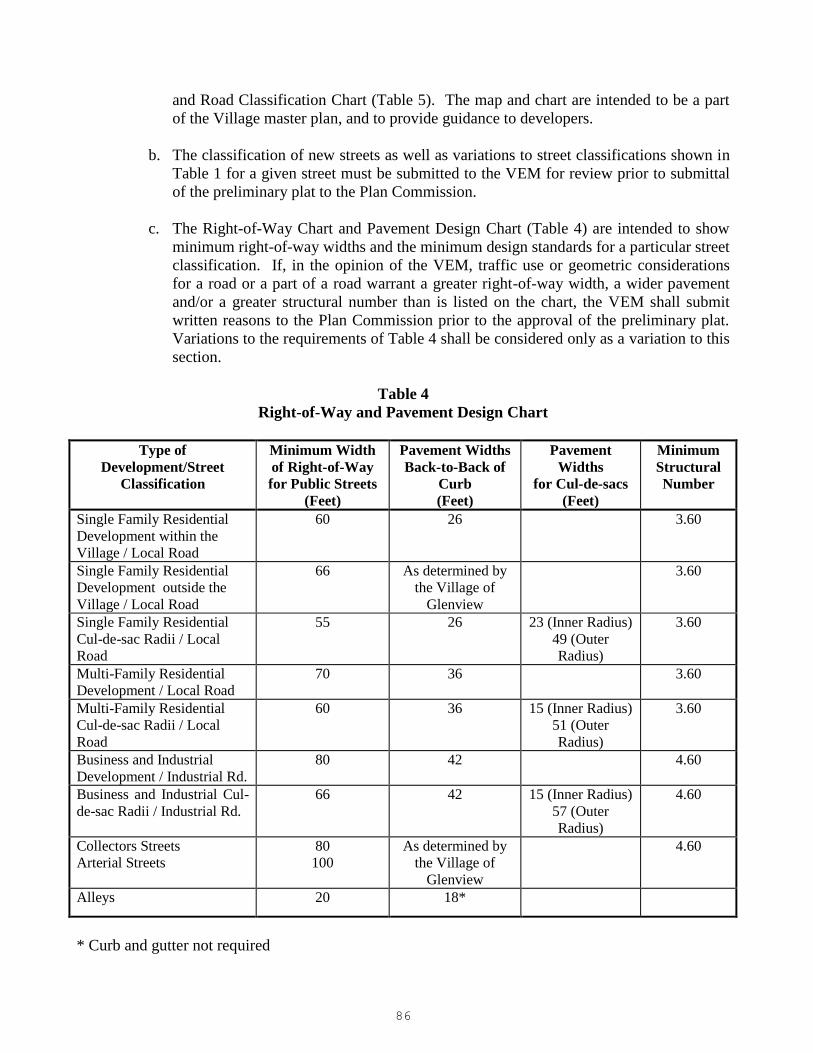
86
and Road Classification Chart (Table 5). The map and chart are intended to be a part
of the Village master plan, and to provide guidance to developers.
b. The classification of new streets as well as variations to street classifications shown in
Table 1 for a given street must be submitted to the VEM for review prior to submittal
of the preliminary plat to the Plan Commission.
c. The Right-of-Way Chart and Pavement Design Chart (Table 4) are intended to show
minimum right-of-way widths and the minimum design standards for a particular street
classification. If, in the opinion of the VEM, traffic use or geometric considerations
for a road or a part of a road warrant a greater right-of-way width, a wider pavement
and/or a greater structural number than is listed on the chart, the VEM shall submit
written reasons to the Plan Commission prior to the approval of the preliminary plat.
Variations to the requirements of Table 4 shall be considered only as a variation to this
section.
Table 4
Right-of-Way and Pavement Design Chart
Type of
Development/Street
Classification
Minimum Width
of Right-of-Way
for Public Streets
(Feet)
Pavement Widths
Back-to-Back of
Curb
(Feet)
Pavement
Widths
for Cul-de-sacs
(Feet)
Minimum
Structural
Number
Single Family Residential
Development within the
Village / Local Road
60 26 3.60
Single Family Residential
Development outside the
Village / Local Road
66 As determined by
the Village of
Glenview
3.60
Single Family Residential
Cul-de-sac Radii / Local
Road
55 26 23 (Inner Radius)
49 (Outer
Radius)
3.60
Multi-Family Residential
Development / Local Road
70 36 3.60
Multi-Family Residential
Cul-de-sac Radii / Local
Road
60 36 15 (Inner Radius)
51 (Outer
Radius)
3.60
Business and Industrial
Development / Industrial Rd.
80 42 4.60
Business and Industrial Cul-
de-sac Radii / Industrial Rd.
66 42 15 (Inner Radius)
57 (Outer
Radius)
4.60
Collectors Streets
Arterial Streets
80
100
As determined by
the Village of
Glenview
4.60
Alleys 20 18*
* Curb and gutter not required

87

88
Table 5
Road Classification Chart
Name From Number of
Segments > 1 To
Functional
Class
Designation
Village Street
Classification
Central Road Glenshire Road (3) Harlem Ave. C C
Central Road-IDOT DesPlaines River Road Milwaukee Ave. MA C
Central Road-IDOT Milwaukee Ave. Glenshire Road C
Chestnut Ave. Patriot Blvd. Waukegan Road C C
Claire Ct. Ravine Way East Cul-de-Sac L I
Compass Road Patriot Blvd. Lehigh Ave. L I
Dearlove Road Central Road (2) Milwaukee Ave. MA C
Dewes St. Shermer Road Waukegan Road L C
East Lake- CCHD West Lake Ave. East Village Limits MA A
Elmdale Ave. West Lake Ave. Pickwick Ave. L I
Glenview Road Milwaukee Ave. (4) East Village Limits MA C
Golf Rd.-IDOT West Village Limits (1) Waukegan Road OPA A
Golf Rd.-IDOT Waukegan Road (1) East Village Limits MA A
Greenwood Road Northbrook Limits (1) Winnetka Road L C
Greenwood Road West Lake Ave. (1) S. of Glenview Road MA C
Greenwood Road S. of Central Road (2) Niles Limits MA C
Harlem Ave. Lehigh Ave. Golf Road C C
Harms Road-CCHD East Lake Ave. South Village Limits C C
Harrison St. Greenwood Road Harlem Ave. L C
I-294 Tri-State-ISTHA North Village Limits South Village Limits I E
Johns Court Johns Dr. East Cul-de-Sac L I
Johns Dr. Old Willow Road Chestnut Ave. L I
Landwehr Road-CCHD Willow Road (3) West Lake Ave. C C
Lehigh Ave. Patriot Blvd. (Signal) Harlem Ave. C C
Milwaukee Ave.-IDOT North Village Limits (3) South Village Limits OPA A
Old Willow Road Willow Road John’s Dr. L C
Overlook Drive Waukegan Road Metra Tracks C I
Overlook Drive-50%
Golf Metra tracks W. of Orchard Ln. C C
Patriot Blvd Willow Road (Signal) East Lake Ave. MA C
Patriot Blvd. Lehigh Ave. (E. Leg) Willow Rd. (Signal) C I
Pfingsten Road-IDOT North Village Limits East Lake Ave. MA C
Pickwick Ave. North Cul-de-Sac West Lake Ave. L I
Ravine Way Old Willow Road Willow Road L I
Ridge Dr. Ravine Way (W. Leg) Ravine Way (E. Leg) L I
Sanders Road-CCHD S. of I-294 Tollway (4) Milwaukee Road MA A
Shermer Road Willow Road UP Railroad L I
Shermer Road Old Willow Road West Lake Ave. L C
Shermer Road US Post Office East Lake Ave. L I
Shermer Road East Lake Ave. Golf Road C C
Sunset Ridge Road-
CCHD Winnetka Road East Lake Ave. C C
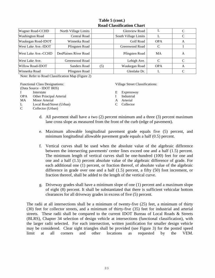
89
Table 5 (cont.)
Road Classification Chart
Wagner Road-CCHD North Village Limits Glenview Road L
C
Washington Road Central Road South Village Limits L C
Waukegan Road-IDOT Winnetka Road Golf Road OPA A
West Lake Ave.-IDOT Pfingsten Road Greenwood Road C I
West Lake Ave.-CCHD DesPlaines River Road Pfingsten Road MA A
West Lake Ave. Greenwood Road Lehigh Ave. C C
Willow Road-IDOT Sanders Road (5) Waukegan Road OPA A
Winnetka Road Pfingsten Road Glenlake Dr. L C
Note: Refer to Road Classification Map (Figure 2)
Functional Class Designations: Village Street Classifications:
(Data Source - IDOT IRIS)
I Interstate E Expressway
OPA Other Principal Arterial I Industrial
MA Minor Arterial A Arterial
L Local Road/Street (Urban) C Collector
C Collector (Urban)
d. All pavement shall have a two (2) percent minimum and a three (3) percent maximum
lane cross slope as measured from the front of the curb (edge of pavement).
e. Maximum allowable longitudinal pavement grade equals five (5) percent, and
minimum longitudinal allowable pavement grade equals a half (0.5) percent.
f. Vertical curves shall be used when the absolute value of the algebraic difference
between the intersecting pavements' center lines exceed one and a half (1.5) percent.
The minimum length of vertical curves shall be one-hundred (100) feet for one and
one and a half (1.5) percent absolute value of the algebraic difference of grade. For
each additional one (1) percent, or fraction thereof, of absolute value of the algebraic
difference in grade over one and a half (1.5) percent, a fifty (50) foot increment, or
fraction thereof, shall be added to the length of the vertical curve.
g. Driveway grades shall have a minimum slope of one (1) percent and a maximum slope
of eight (8) percent. It shall be substantiated that there is sufficient vehicular bottom
clearances for all driveway grades in excess of five (5) percent.
The radii at all intersections shall be a minimum of twenty-five (25) feet, a minimum of thirty
(30) feet for collector streets, and a minimum of thirty-five (35) feet for industrial and arterial
streets. These radii shall be compared to the current IDOT Bureau of Local Roads & Streets
(BLRS), Chapter 34 selection of design vehicle at intersections (functional classification), with
the larger radii selected. For each intersection, written justification for smaller design vehicle
may be considered. Clear sight triangles shall be provided (see Figure 3) for the posted speed
limit at all corners and other locations as requested by the VEM.

90
91
h. Street widening for the primary purpose of providing on street parking where already
existing per Village aerial mapping is only permissible on non-curbed streets and
where approved by the VEM by obtaining a Village permit after submittal of a hold
harmless agreement for ownership and maintenance of the widened pavement section.
The property owner shall be responsible to replace or repair any widened pavement
section at the owner’s cost. The Village has no responsibility to repair or replace any
street widening.
i. New public alleys shall be constructed of reinforced PCC pavement.
j. The improvement or extension of existing alleys should comply with the following, at
a minimum, if the adjacent property owner wishes to extend an alley to their property:
Engineering plans must be developed by an Illinois Licensed Professional
Engineer and reviewed by the Village.
The Engineering plans must include a plan for a drainage system for the alley such
that the storm drainage does not negatively impact the other property owners on
the alley. The alley drainage system shall be connected to the existing Village
storm sewer system. Any damage caused by the connection will need to be
repaired to the satisfaction of the VEM. The responsibility to upgrade an existing
Village storm sewer for alleys shall be by the Village generally through the Capital
Improvement Program.
The alley may be constructed of gravel, concrete, or asphalt, consistent with the
existing surface, if the alley is to be privately maintained. If requested to be
publicly maintained, the alley shall be reinforced PCC. The approach and apron to
the alley from the public street must be concrete in all cases.
The alley width shall be a minimum eighteen (18) feet wide and extend lengthwise
to the limits of the extended property line.
Where an alley is proposed, all adjacent property owners must be notified and
concur, unless otherwise determined by the Village Board to be in the greater
public interest.
k. All frontage not utilized for public sidewalk purposes, including parkway areas,
driveways, private walks, etc. shall be maintained by the adjacent property owner and
should consist as grass.
l. Intersections on curved alignment should utilize flat horizontal and vertical controls
for hazard reduction. All three (3) or four (4) leg intersections shall be at right angles
only.
m. Drainage routing and collection structures should prevent flow across roadways,
intersections, crosswalks and major driveway entrances.
n. For existing roads with no existing curb and gutter, the minimum pavement width shall
be no less than twenty (20) feet edge-to-edge, except for streets in Glen Oak Acres
where the minimum width shall be no less than sixteen (16) feet edge-to-edge for two-
way traffic areas and no less than twelve (12) feet edge-to-edge in one-way traffic

92
areas.
o. No asphalt work is allowed after November 1st without advance (prior to placement)
written authorization from the VEM. This authorization will in no way void the
contractor’s and developer’s guarantee on the work done.
p. Lane closures on State or County routes shall be allowed between the hours of 9:00am
to 3:00pm, unless authorized in writing by IDOT or CCDTH respectively and
approved in writing by the VEM.
3. “Private Streets” shall comply with the following:
a. Private streets are treated the same as public roadways in reference to their design
material and inspections as described herein and as approved by the VEM to ensure a
safe and quality product for the property owners.
b. “Half Streets” are prohibited. Private streets shall be constructed no less than 14 feet
wide with a minimum structural value of 2.50.
c. Streets that are to be privately owned and maintained must be clearly noted on the
plans. The Village has no interest of accepting ownership and maintenance
responsibility of a private street right-of-way, or other site improvements without all
current Village standards being met in advance, and submittal of private ownership
maintenance records.
d. Private street maintenance and responsibility includes all pavement components and
the related drainage system.
4. Pavement length shall comply with the following:
a. Maximum residential block length shall be thirteen-hundred and twenty (1,320) feet
(Ref. Code 66-171).
b. Cul-de-sacs shall have a maximum length of five-hundred (500) feet.
5. Public pavements (including parking areas) shall be designed and constructed so as to
obtain a minimum sixty (60)year service life (resurfacing at intervals of twenty (20) and
forty (40) years, reconstruction at sixty (60) years) or greater with minimal maintenance
after acceptance of the pavement by the Village. Show all pavement design calculations
on the Engineering plans. Table 6 indicates the approved materials which can be used for
roadway construction within the Village of Glenview. Listed with these materials are the
coefficients to be used for approved pavement structural number. The coefficients, when
multiplied by the thickness of the materials, will yield the structural number.

93
Table 6
Allowable Pavement Construction Materials
Structural Materials Minimum Strength
Requirements
Structural Number
Coefficients (SN)**
IBR PSI
Hot-Mix Surface 0.40
Course (Table 4)
Base Course:
Aggregate, Type B
Uncrushed 50 0.10
Crushed (100%) 80 0.13
Aggregate, Type A 80 0.13
Hot-Mix Asphalt Base Course
(formerly BAM)
0.24 – 0.33
Hot- Mix Binder
Course 1 (Table 4) 0.33
Portland Cement
Concrete (New) 3500* 0.50
* Twenty-eight (28) day design compressive strength
** SN valves shall be multiplied by material thickness in inches
6. Pavement materials and minimum thickness shall comply with the following: The
MINIMUM thicknesses of each component are required as indicated below, and one or
more component layers shall be increased (in one-half (.05) inch increments only) to meet
the required minimum structural number.
a. Rigid pavement shall comply with the following:
Minimum four (4) inches of Aggregate Base Course Material, Type B. Milled
asphalt meeting Aggregate Base Course (crushed) specifications cannot be used
for Aggregate Base Course, Type B.
A six (6) inch minimum for Sn equals 3.60 and eight (8) inch minimum for Sn
equals 4.60 of Portland Cement Concrete (PCC) pavement designed in accordance
with IDOT standards for Class PV concrete. All Portland Cement Concrete shall
be treated with a protective coat application per IDOT specifications in the same
calendar year as concrete placement.
Concrete pavements shall be reinforced in accordance with IDOT standards as
directed by the VEM.
PCC shall have a minimum fourteen (14) day compressive strength of three-
thousand and five-hundred (3,500) psi, with five (5) percent to eight (8) percent air
entrainment, and three-quarter (¾) inch to one and a half (1½) inch slump. If
partial replacement of cement with fly ash is approved by the VED, the amount of
cement replaced shall not exceed 15 percent by weight per IDOT standard
specifications.
94
In those cases where undercut backfill may be needed for the subgrade, the use of
nine (9) inches of Aggregate Material (i.e. crushed concrete) meeting Aggregate
Base Course gradation and a three (3) inch milled asphalt cap may be used. Milled
asphalt or the blending of asphalt millings with crushed concrete or other crushed
aggregate material is not allowed for use in either the subgrade or base material.
Any crushed concrete used shall be free of building debris; such as particles of
brick, wood, wire, plastic, etc.
Berths provided in non-residential areas for loading and unloading of materials or
merchandise from vehicles must be constructed of a minimum eight (8) inch
reinforced concrete pavement over four (4) inches of Aggregate Base Course
Material.
All outside areas used for the storage of materials, products or vehicles in non-
residential areas shall be a minimum of six (6) inch P.C.C. or Portland Cement
Concrete pavement.
b. Flexible base pavement shall comply with the following:
Minimum four (4) inches of Aggregate Base Course (crushed) Material, Type B.
Milled asphalt meeting Aggregate Subgrade specifications cannot be used for
Subbase Granular Material.
Seven and a half (7.5) inch minimum for Sn equals 3.60 and ten and a half (10.5)
inch minimum for Sn equals 4.60 Hot-Mix Asphalt Binder Course according to the
most current IDOT standard, placed in multiple lifts with maximum lift thickness
of four (4) inches.
One and a half (1.5) inch minimum Hot-Mix Asphalt Surface Course, according to
the most current IDOT standard.
In those cases where undercut backfill may be needed for the subgrade, the use of
nine (9) inches of Aggregate Material (i.e. crushed concrete) meeting Aggregate
Base Course gradation and a three (3) inch milled asphalt cap may be used. Milled
asphalt or the blending of asphalt millings with crushed concrete or other crushed
aggregate material is not allowed for use in either the subgrade or base material.
Any crushed concrete used shall be free of building debris; such as particles of
brick, metal, wood, wire, plastic, etc.
Hot-Mix Asphalt shall be placed in lifts per Table 7.
Butt joint tapers shall be at a rate of three (3) feet in length per inch of milling
thickness. Taper length shall be at a rate of twenty (20) feet per inch of milling
thickness for all non-local roads or at a rate of ten (10) feet of milling thickness for
all local roads (see Table 4 for street classifications).

95
Table 7
Hot-Mix Asphalt Mix Selection *
ADT Pavement Material Thickness per Lift
Min. Max.
Surface Course
0 - 10,000 Hot-Mix Asphalt Surface Course, Mix “D”, IL-9.5, N50;PG 64-22 1.5" 3.0"
10,000 - 25,000 Hot-Mix Asphalt Surface Course, Mix “D”, IL-9.5, N70;PG 64-22 1.5" 3.0"
Binder Course
0 - 10,000 Hot-Mix Asphalt Binder Course, IL-19, N50; PG 64-22 2.5" 4.0"
10,000 - 25,000 Hot-Mix Asphalt Binder Course, IL-19, N70; PG 64-22 2.5" 4.0"
*Comply with the most recent IDOT Hot-Mix Asphalt Mix Selection and QA/QC requirements
7. Subgrade shall comply with the following:
a. All subgrade material shall have a minimum Illinois Bearing Ratio (IBR) of 3.0. All
organic or otherwise unsuitable subgrade material, including subgrade material having
an IBR less than 3.0, shall be removed and replaced with inorganic suitable (non-frost
susceptible) fill material (see Section IV-G.6 above), or the pavement designed to
compensate for the marginal soil condition. The soil support IBR values selected for
use by the Engineer shall represent a minimum value for the (existing or fill) subgrade
soils. Verification of subgrade IBR values must be submitted to the VEM for
approval.
b. All subgrade embankment material (or backfill) shall be compacted to the
requirements of Art. 205.06 of the IDOT Standards, except the top foot of subgrade
shall be compacted to at least ninety-five (95) percent Modified Proctor density in
accordance with AASHTO T-181.
8. Pavement open-cuts/ auguring shall comply with the following:
a. Open cuts of Village owned pavement are restricted to those that have not been
resurfaced, rehabilitated or reconstructed within the past five (5) years, unless
otherwise approved in writing by the VEM. All restoration/installation of mains,
pipes, conduits, etc. within this five (5) year time period shall be done by approved
lining, pipe boring, or jacking methods. Concrete slab replacement shall be as full
slabs only unless otherwise directed by the VEM. Other issues that may become a
factor in not allowing an open cut include (but not limited to):
Motorist inconvenience and vehicle delays.
Roadway is a direct route for emergency vehicle use.
Known locations for running sand or unstable material.

96
Utility impacts which may cause excessive road closure.
All open cuts that are permitted within an existing paved surface area are required to
use CA-7 crushed aggregate or controlled low strength material (CLSM) Mix 1 (only
if required by Village Engineering). Where the cut extends to the edge of the
pavement, the flowable fill should extend one (1) foot beyond the outside edge of
pavement.
The Village reserves the right to require grinding and resurfacing along the full
frontage of a development parcel. In particular, this requirement may be used in cases
where pavement patching of an existing roadway is under an existing escrow.
b. All pavement to be replaced shall be patched in kind, with all saw cutting at full depth.
Temporary use of steel plates will not be allowed from November 1st and April 30
th
unless otherwise received in writing from the VEM in advance. Steel plates shall be
placed over all PCC patches until concrete is cured for a minimum of three (3) days.
Patching shall comply with the following:
For flexible pavement, patches shall have a minimum of seven (7) inches (two
(2) lifts) of binder course placed over a minimum of four (4) inch compacted
subbase of granular material (CA-6). A minimum one and a half (1.5) inches
of surface course shall be laid over the binder course.
For rigid pavement, patches shall be replaced with a minimum fourteen (14)
day, three-thousand and five-hundred (3,500) psi, six (6) inch thick PCC (6.1
bag mix), conforming to IDOT Standards for Class PP concrete, placed over a
minimum four (4) inch compacted granular base course (CA-6). The existing
pavement shall have No. 6 epoxy-coated dowel bars, two (2) feet in length,
drilled at twenty-four (24) inches on center, grouted in place. All PCC patches
shall be treated with a protective coat application. No fly ash is allowed in the
PCC mix. Patching shall be required on an entire slab basis or as determined by
the VED.
For composite pavement patches with a concrete base and asphaltic surface, the
concrete shall be placed at the same thickness as the existing concrete
pavement, or a minimum of six (6) inches thick, whichever is greater, and
placed over a minimum four (4) inch compacted granular base course (CA-6).
Number 6 epoxy-coated dowel bars, two (2) feet in length, shall be placed at
twenty-four (24) inches on center, grouted in place. Bituminous concrete
surface course shall be placed at a minimum two and a half (2-1/2) inch
thickness over the concrete.
9. Pavement testing shall comply with the following:
a. New pavement will be tested (Dynaflect pavement evaluation program) by a Village
appointed consultant to ensure that the structural strength of the pavement will provide
a minimum of sixty (60) years of service life (resurfacing at intervals of twenty (20)
and forty (40) years reconstruction at sixty (60) years) after acceptance. The cost for
said testing shall be borne by the Owner/Developer. This testing shall be completed
and approved by the Village immediately (less than 30 days) prior to the placement of
the final surface course of bituminous concrete.

97
b. The pavement evaluation program shall generally embody the following
testing/pavement evaluation techniques:
Environmental study (frost cycle, drainage, etc.).
Pavement surface evaluation.
Soil borings at approximately one location per block per street.
Dynamic pavement deflection analysis (Dynaflect machine or equal correlated
with Benkelman Beam or equal).
The program shall evaluate the existing condition of the base and binder course in
maximum 200 foot sections. If the pavement section is not projected to meet a life
expectancy of sixty (60) year service life (resurfacing at intervals of twenty (20) and
forty (40) years, reconstruction at sixty (60) years) or more, then the report shall
propose asphalt overlays in excess of the surface course design thickness or pavement
reconstruction to bring the new pavement section to a fifteen (15) year life expectancy.
The VEM shall evaluate the results of the report and inform the contractor or
developer as to the required pavement operation for each section in question.
c. The Dynaflect pavement evaluation program shall not be considered valid unless the
wearing surface was applied during the same construction season.
d. After receipt of the Dynaflect pavement evaluation program report, the VEM will
review said reports and will perform an inspection of the existing base and binder
courses. All base and binder course failures will then be repaired to the VEM
satisfaction. This may include, but may not be limited to, crack grouting, crack filling
and crack filling.
e. If additional pavement testing is performed as part of the five (5) year evaluation
program for all Village pavement, and the development has not been accepted by the
Village at the time of testing, the applicable costs of the evaluation program shall be
paid by the developer.
10. Curbs shall comply with the following:
a. Curb and gutter shall be M-3.12 mountable type adjacent to residential properties
unless otherwise approved or directed by the VEM (refer to details). All (public and
private) commercial streets, industrial streets and parking lots shall use B-6.12 curb
and gutter.
b. Curbs shall be constructed with a minimum fourteen (14) day, 3500 psi, PCC (6.1 bag
mix) in accordance with IDOT Standards for Class SI concrete. Two (2) continuous
epoxy coated No. 4 rebars shall be continuous at utility trench crossings, except across
expansion joints. Reinforcement shall extend five (5) feet beyond trench walls. One
(1) inch thick expansion joints shall be placed at sixty (60) foot (maximum) intervals,
and contraction joints shall be at fifteen (15) foot intervals and at all points of
curvature. Two (2) Epoxy coated No. 6 smooth dowel bars (eighteen (18) inches
long), with greased caps, shall be provided at the location of all expansion joints.

98
Curbs shall be placed over a minimum compacted four (4) inch aggregate base (CA-6).
c. Both the front and back of curb (below grade) shall have finished surfaces without
voids.
d. Curbs shall be protected from ongoing project construction activity to minimize or
eliminate chipping, cracking, gouging or other visible damages. The VEM will solely
determine any curb sections that need to be removed and replaced, generally before
placement of adjacent surface course(s). Structure conditions are not the sole factor
for which removal and replacement is determined.
e. No reduction in curb width (front to back) shall be utilized to remove damaged
portions as a permanent repair measure for acceptance by the Village. Curb cuts shall
be full depth only.
f. Epoxy repairs, where directed by the VEM, shall be by use of an IDOT approved
product and placement.
g. Horizontal saw cutting of existing driveway curbing in lieu of removal and
replacement (where allowed) shall commence after the removal of the existing
driveway and prior to placement of the new driveway. Proposed curb section to be cut
requires preinspection by the VEM to determine if the curb qualifies for this type of
work and existing curb is in a sound structural condition as determined solely by the
VEM. Saw cutting shall be from the back (parkway side) with equipment similar to
that manufactured by Kotkurb of Montreal Canada. No handsaw cutting will be
allowed. Saw cut shall be uniform with a half (0.5) inch to three-quarter (¾) inch lip at
gutter and otherwise comply with IDOT standards for depressed curb. Saw cutting
shall leave no rough edges on curb. Standard curb flow line shall be maintained at all
times. Curb shall be sealed with an approved sealer after completion of curb cutting.
The VEM shall solely determine if the existing curb, gutter or pavement is damaged,
chipped or cracked in any way from the curb cutting operation and will instruct the
contractor to remove and replace the damaged section and make repairs to the
satisfaction of the Village. All additional material and labor will be performed at the
developer’s expense. It is not the intent of the VEM to allow curb cuts to be used
exclusively throughout a development or portion thereof as the design standard.
h. All buffalo box, sanitary sewer and storm sewer service locations shall be indicated by
a VEM approved stamp or sawcut mark on the curb (or pavement surface as directed
by the VEM) with a four (4) inch by four (4) inch “W”, “S” or “ST”, respectively, as
the case may be. Any abandonment/removal of service lines requires removal of the
stamped or sawcut marking at the time of abandonment/removal.
i. The vertical and horizontal alignment of all PC concrete curb shall not vary in any way
from the dimensions and elevations shown on the plan. The petitioner will remove all
curb improperly constructed at the incorrect vertical and horizontal alignment and
replace with curb properly located.
j. Curb head and gutter shall be pitched to drain toward face of curb unless otherwise
shown in the plans or directed by the VEM.

99
11. Sidewalks shall comply with the following:
a. Public sidewalks are to be constructed of a minimum five (5) inch thick by five (5)
foot wide, (IDOT Class SI) PCC with five (5) percent to eight (8) percent air
entrainment. All Portland Cement Concrete shall be treated with a protective coat
application. Sidewalks shall be placed over a minimum compacted three (3) inch
aggregate base (CA-6). No milled asphalt shall be used for base material. Private
sidewalks shall be constructed to a minimum four (4) inch thickness. If partial
replacement of cement with fly ash is approved by the VEM, the amount of cement
replaced shall not exceed (15) percent by weight per IDOT specifications.
b. Public walks shall be constructed through all driveways and shall be thickened to a
minimum of six (6) inches, or the thickness of the driveway, if greater.
c. Sidewalk shall be constructed one (1) foot off the street R.O.W. line unless otherwise
directed by the VEM.
d. Two (2) equally spaced, epoxy coated No. 4 rebars shall be centered over all utility
trenches. Bars shall extend a minimum of five (5) feet beyond the walls of the utility
trench.
e. Sidewalk shall be continuous through all driveway areas.
f. A one half (1/2) inch thick expansion joint, with premolded joint filler, shall be
provided at fifty (50) foot intervals, and contraction joints (one and a quarter (1¼) inch
deep by a one-eighth (1/8) inch wide shall be at five (5) foot intervals. The contractor
shall saw-cut the existing sidewalk at the beginning and end of each section to be
removed. A one half inch preformed expansion joint shall be installed wherever a
proposed sidewalk abuts an existing concrete sidewalk, concrete driveway, curb or
combination curb and gutter.
g. Sidewalk shall comply with ADA requirements. Ramping and sloping of sidewalks,
as well as surface texture, at all intersections shall be designed and constructed in
accordance with current IDOT Handicap Standards (including 424001-06, 424006,
424011, 424016, 424021, 424026 and 424031) and Specifications. Identify all
locations of detectable surfaces on plans. All sidewalks and shared-use trails shall use
truncated domes of contrasting color at curb ramps. Color variations other than
Federal standard color 30166, brick red, shall be directed to the IDOT District I Field
Engineer and if approved, to the VEM for final approval before placement. Side curbs
are not to be constructed with ADA curb ramps. The following prefabricated
truncated dome panels are acceptable to the Village of Glenview:
ADA solutions, P.O. Box 3, North Billerica, MA 01862
Armorcast Products, 13230 Saticoy Street, North Hollywood, CA 91605
h. Where handicap spaces are located adjacent to a sidewalk, a curb ramp per IDOT
specifications shall be located in the access isle (striped portion) of the handicap stall.
i. All concrete sidewalks poured when temperatures are over forty (40) degrees shall be
treated with a protective coat application of linseed oil, or curing compound

100
equivalent.
j. A minimum clear zone of five and a half (5.5) feet between obstructions (signs, lights,
buildings, benches, trees, etc.) shall be maintained on all public sidewalks.
k. Side forms shall use lumber with a normal thickness of two (2) inches and a depth
equal to the sidewalk thickness specified or of steel with equal rigidity. Two (2) inch x
four (4) inch forms will not be allowed. Side forms shall be held securely in place by
stakes or braces, with the top edges of the forms true to grade. The forms shall be
lightly coated with oil prior to placing concrete. The contractor is responsible for
maintaining proper barricades until overdig area is backfilled.
l. Sidewalk cross slope design shall be two (2) percent. No approval or acceptance of
public sidewalk shall be given for a constructed cross slope equal to or less than one
(1) percent, or more than four (4) percent. Longitudinal slope shall not exceed five (5)
percent without approval of the VEM.
12. Retaining wall structures shall comply with the following
a. Drainage and backfill conditions for all retaining walls must be detailed and noted.
Grading slopes shall follow Section-IV.A. The retaining wall and associated grading
shall not interfere with existing swales or drainage patterns or adversely impact
adjacent properties.
b. Retaining walls shall not be constructed within any easement unless specifically
designed and approved by the VEM. Any retaining walls to be constructed in a utility
easement shall require waiver letters from all utility companies prior to VEM approval
and the start of any related construction.
c. Retaining walls shall not be constructed within ten (10) feet of rear or side lot lines. If
an easement of greater than ten (10) feet is present along any property line, the
retaining wall shall not be constructed within the easement.
d. The retaining wall policy outlines the permitted use of retaining walls. Developers or
homeowners that choose to utilize a retaining wall shall agree to and comply with the
following:
Any solid structure in excess of twelve (12) inches in height along any exposed
elevation portion and measured from the final grade at the base of the wall to the
top of the wall, and whose purpose is to contain any soil and/or other materials
shall be considered a retaining wall. Retaining walls shall not be constructed of
wood unless approved in writing by the VEM.
The design and construction of any retaining wall shall meet or exceed the current
Village standards or the more stringent requirements of any overriding regulations.
A permit shall be required prior to any retaining wall being constructed. The
following items shall be included in the permit application:
o Material of the retaining wall.

101
o A grading plan consisting of both existing and proposed grades.
o Cross sectional detail of the retaining wall, drainage system and related work.
o Plat of Survey for the property.
Retaining walls, thirty-six (36) inches or more in height, shall be designed and the
plans shall be dated, sealed, and indicate the expiration date of the Illinois
Registered Structural Engineer. Pre-manufactured walls must also conform to this
requirement.
Retaining walls of thirty (30) inches or more in height shall require a permanent
fixed physical barrier at the top of the wall.
The property owner shall be required to sign a Hold Harmless Agreement for
ownership and maintenance of the retaining wall prior to the start of construction.
No private retaining walls shall be designed or constructed within the Village
right-of-way, nor shall they conflict with clear sight lines of vehicles or
pedestrian/bikeways within public right-of-way.
Refer to the current Engineering Standards, Section IV-G. for specific construction
details.
13. Reinforced concrete structures that are cast-in-place, unless otherwise directed by the
VEM, shall be constructed with epoxy coated reinforcement bars.
14. Parkway trees shall be planted with a minimum of thirty (30) feet and not in excess of
sixty (60) feet separation throughout the subdivision and in commercial developments. In
single family residential areas, the selection of two (2) inch minimum standard tree species
as well as the planting of these trees shall be the responsibility of the Village Tree
Preservation Officer (TPO) and Public Works Department. The Public Works Department
shall use a portion of the development’s posted escrow to defray its cost for time, material
and overhead. Plantings in a cul-de-sac center island, shall be deciduous trees, approved
and planted by the Village TPO and Public Works Department, and shall be maintained by
the Homeowner’s Association, or a private contractor. All existing trees to remain on site
are to be protected from damage throughout construction. Protection shall consist of a
suitable barrier placed around the drip-line of the tree, in accordance with the Village’s
Tree Standard Manual. If any trimming or removal of parkway trees is required, the
contractor shall contact the Village TPO at least five (5) days prior to beginning this work.
Selection and/or placement of trees by the developer will only be allowed with additional
requirements including but not limited to:
a. All trees shall be pre-inspected at the nursery by Village Tree Preservation Officer
(TPO) prior to dig-up.
b. No tree plantings are allowed from Oct. 31st through March 31
st.
c. Spring plantings are highly preferred. Written request with justification shall be
submitted for review and approval prior to other planting times.
d. Each tree installed shall be tagged (obtain for Public Works) and/or located by GPS

102
method (submit disk copy to VEM) which shall identify the month and year of
installation.
e. A landscape map (2 copies) with date of installation or replacement shall be submitted
prior to Oct. 1st for inspection. If submitted later, the inspection will occur the
following spring.
f. Developer shall replace trees no later than the spring following the inspection.
g. Replaced trees shall be re-inspected within twelve (12) to eighteen (18) months (fall
time frame) to determine if additional replacements are required.
h. Developer shall submit to homeowners upon occupancy any relevant information
supplied by Village regarding tree preservation (including watering, mulching, etc.).
15. Continuous street lighting is not specifically required by the Village, however, any street
lighting system provided in any development must be acceptable to the Village, as
follows:
a. All work shall include the installation of all fuses, lamps, grounding wires, conduit,
foundations, standards, mast arms, luminaries, fuses, lamps, controls, handholes,
trenching and backfill.
b. All work done and material used in connection with the installation of the street
lighting system shall be in accordance with the specifications of the National Electrical
Code, appropriate IES Nema Standards, Underwriter’s Laboratory approvals,
AASHTO criteria, and the Village Engineering Standards. Standard “Sternberg”
fixtures shall be used unless other required by the VEM.
c. All commercial driveway, street and sidewalk crossings shall be provided with a cable
duct raceway for underground cable consisting of two (2) inch diameter galvanized
rigid steel conduit with two (2) inch insulating fiber bushings. Cable duct shall be
installed in trenches six (6) inches wide by twenty-four (24) inches deep, and
backfilled with compacted suitable fill material.
d. Junction boxes as approved by the Village shall be provided in close proximity to each
pole for cable slack needed by maintenance personnel.
e. All lighting standards shall be located with the pole centerline located three (3) feet
behind the back of the curb line, unless otherwise noted on the drawings and approved
by the VEM.
f. Upon completion of installation, and at a time convenient to the owner and/or the
Village, the contractor shall conduct all operating tests required by the owner and/or
the Village. The contractor shall furnish any and all instruments and personnel
required to conduct the tests.
g. Upon completion of all work, the contractor shall provide the VEM with a clear and
legible as-built drawing(s) which shall include splices, controls, etc. Unless otherwise
agreed to specifically by the Village Board, all street lighting shall be privately owned
and maintained.

103
16. Traffic signals shall comply with the following:
a. Design shall strictly follow IDOT District I traffic signal design guidelines (latest
edition).
b. Traffic control equipment shall include phone connection for data transfer.
c. Proposed signals shall be interconnected to existing signals as directed by the VEM.
d. All traffic lenses including pedestrian heads shall be light emitting diode (LED).
e. Provide a full traffic activated controller, Type five (5) or as directed by the VEM.
f. Emergency vehicle pre-emption systems shall be included on all traffic signals and be
compatible with existing Village equipment (New equipment shall be Global Traffic
Technologies).
g. A battery back-up system approved by the VEM, capable of three (3) hour minimum
battery life to provide one hour of full functioning signals and two (2) hours of
flashing red shall be installed in the controller cabinet (Type IV cabinet with an
external battery enclosure).
h. All traffic signals shall be submitted to the Village Traffic Committee for review.
i. Pedestrian crossings shall include audio signals unless otherwise directed by the VEM.
17. Vacant lots within a proposed subdivision (or development) shall be maintained in
accordance with criteria established by the Village Department of Public Works.
18. Traffic Control shall comply with the following:
a. Engineering traffic control plan as required by the VEM demonstrating the protective
measures and devices that will be employed consistent with the MUTCD, to prevent
injury or damage to persons or property and to minimize disruptions to efficient
pedestrian and vehicular traffic.
b. All work within public right-of-ways and on private roads shall conform to the
requirements of the latest edition of the MUTCD:
When an opening is made into the existing pavement.
When construction takes place adjacent to the edge of the existing pavement.
When a utility crossing is made beneath the existing pavement.
When it is necessary to close a lane of traffic due to construction operations or any
other work within the right-of-way which affects traffic flow (pedestrian and
vehicular).
c. Permission for any lane or road closures shall be obtained from the Village, IDOT or
104
the CCDTH prior to commencing construction. Signing will be required in strict
conformance with the MUTCD. No construction operation shall commence until such
time that all required signs and barricades have been erected. All work shall be phased
so to minimize interference with traffic flow.
d. Unless authorized by the Village in writing in advance, no street openings shall extend
beyond the end of the working day.
e. Advance construction message boards shall be placed a minimum of seventy-two (72)
hours prior to the start of construction as directed by the VEM.
19. Signing, pavement markings and mailboxes shall comply with the following:
a. All pavement signing (street names, regulatory, etc.), pavement marking and mailbox
locations are to be submitted to the Village Traffic Committee for review. The
Committee represents Village Departments such as Police, Fire, Public Works, and
Community Development Department.
b. All pavement markings shall be thermoplastic pavement marking in accordance with
the appropriate material specifications of the “Standard Specifications for Traffic
Control Items” except parking stall lines within parking lots, which may be painted.
Pavement marking tape shall be installed and maintained on all binder course placed
pavement which is opened to traffic. All tape shall be substantially removed prior to
final surfacing.
c. Mailboxes shall be installed at such locations approved by the Village in conformance
with the standards of the United States Post Office. No mailbox turnouts are allowed
in the public right-of-way. No mailboxes shall conflict with clear sight lines of
vehicles or pedestrian and bikeways within the public right-of-way.
d. All street signing material to meet the requirements of the MUTCD, ASTM Standards.
e. Sign post hardware including rain cap, drive rivets, nylon washers, medium corner bolt
and flange nut shall meet the following:
3/8” Drive rivets with nylon washer
5/16” medium corner bolt with nut
Galvanized aluminum rain cap for 2” OD Post ARC200
Cherry Mate Rivets – ¼” all aluminum Sign Mate Rivet use with 2” post,
SMRA25-34 including the dowel pin and the rivet
Cherry Mate Spacer PVCSP175 PVC spacer used with #34 Cherry Mate Rivet
f. Street name sign sizing shall be determined by the VEM and must meet the following:
Nine (9) inch sign blanks shall be a nine (9) inch wide by variable length 0.080
gauge aluminum blanks. Signs shall have one and one-half (1 ½) inch radius
corners with three-eighths (3/8) inch holes one (1) inch on center from the top and

105
bottom edge in the exact middle if the sign and five-sixteenths (5/16) inch holes
one (1) inch on center from the ends in the exact middle of the sign ends. The
reflective sheeting shall be white high intensity prismatic reflectivity to be applied
per manufacturers specifications on one side only.
Six (6) inch sign blanks shall be six (6) inches wide by variable length 0.080 gauge
aluminum blanks. Sign shall have one and one half (1 ½) inch radius corners with
three-eighths (3/8) inch holes one (1) inch on center from the top and bottom edge
in the exact middle of the sign and five-sixteenths (5/16) inch holes one (1) inch on
center from the ends in the exact middle of the sign ends. The reflective sheeting
shall be white high intensity prismatic reflectivity to be applied per manufacturers
specifications on one side only.
Nine (9) inch signs finished shall be nine (9) inches wide by variable length 0.080
gauge aluminum blanks. Sign shall have one and one half (1 ½) inch radius
corners with three-eighths (3/8) inch holes one (1) inch on center from the top and
bottom edge in the exact middle of the sign and five-sixteenths (5/16) inch holes
one (1) inch on center from the ends in the exact middle of the sign and five-
sixteenths (5/16) inch holes one (1) inch on center from the ends in the exact
middle of the sign ends. The reflective sheeting shall be white high intensity
prismatic reflectivity to be applied per manufacturers specifications on one side
only. The legend shall be cut from green electro cut film and applied leaving a
three-eighths (3/8) inch margin. A one-half (1/2) inch rounded margin cut shall be
used on the outside border. Lettering shall be six (6) inch uppercase for the first
letter in the street name and minimum four and one-half (4 ½) inch lower case
letters for the other letters in the street names. Series “C” style lettering to be used
as standard. Series “B” for longer signs can be used if approved by the VEM. An
area for the Village to apply a stick on logo, sized five (5) inches in diameter, must
be left at the left side of the sign for Village application. A computer made mock-
up of the sign shall be approved by the VEM before sign fabrication.
Twelve (12) inch signs finished shall be twelve (12) inches wide by variable length
0.080 gauge aluminum blanks. Sign shall have one and one-half (1 ½) inch radius
corners with three-eighths (3/8) inch holes one (1) inch on center from the top and
bottom edge in the exact middle of the sign and five-sixteenths (5/16) inch holes
one (1) inch on center from the ends in the exact middle of the sign ends. The
reflective sheeting shall be white high intensity prismatic reflectivity to be applied
per manufacturer’s specifications on one side only. The legend shall be cut from
green electro film and applied leaving a three-eighths (3/8) inch margin. A one-
half (1/2) inch rounded margin cut shall be used on the outside border. Lettering
shall be eight (8) inch uppercase for the first letter in the street name and minimum
six (6) inch lower case letters for the other letters in the street name. Series “C”
style lettering to be use as standard. Series “B” for longer signs can be used if
approved by the VEM. An area for the Village to apply a stick on logo, sized five
(5) inches in diameter, must be left at the side of the sign for Village application.
A computer-made mock-up of the sign shall be approved by the VEW before sign
fabrication.
g. Square steel posts shall conform to the standard specifications for hot-rolled carbon
sheet steel, structural quality, ASTM designation A570, grade 50. The square tubing
shall be given triple coated protection by an in-line application of hot-dipped zinc

106
(galvanized) per AASHTO M-120, followed by chromatic conversion coating and a
clear organic exterior coating. The inside surface shall be given corrosion protection
by a double in-line application of a full zinc-based organic coating tested in
accordance with ASTM B117 standards. The cross section of the post shall be square
tubing formed of 14 gauge (.083 U.S.S. gauge) steel, carefully formed into size and
corner induction welded in such a manner that neither weld nor flash shall interfere
with telescoping properties. Punched knock-out diameter shall be seven-sixteenths
(7/16) inches +/- one sixty-fourth (1/64) inch on one (1) inch centers, on all four (4)
sides down the entire length of the post. Knockouts shall be on the center line of each
side in true alignment and opposite of each other. Knockouts shall not be punched
open.
The cross-section posts shall be two (2) inches by two (2) inches, 14 gauge, 2.16 lbs/ft.
and be a length of ten (10) feet. The finished posts shall be straight and have a
smooth, uniform finish. All ends shall be free from burrs and shall be cut square.
h. Ground anchors steel posts shall conform to the standards specifications for hot rolled
carbon sheet steel, structural quality, ASTM designation A570, Grade 50. The cross
section of the post shall be square tube formed of 12 gauge (.105 U.S.S. gauge) steel,
carefully rolled to size and shall be welded directly in the corner by high frequency
resistance welding and externally scarfed to agree with the corner radii. Ground
anchors shall be manufactured from hot-dipped galvanized steel conforming to ASTM
A653, G90, structural quality, Grade 50, Class 1. The corner weld is zinc coated after
scarfing operation. The steel is also coated with a chromate conversion coating and a
clear organic polymer topcoat. Both the interior and exterior of the post shall be
galvanized. Perforated ground posts shall be two and one-fourth (2 ¼) inches by two
and one-fourth (2 ¼) inches, 12 gauge 2.42 lbs/ft and be a length of thirty-six (36)
inches. Holes shall be seven-sixteenths (7/16) inches +/- one sixty-fourth (1/64) inches
in diameter on one (1) inch centers on all four sides down the entire length of the
anchor. Holes shall be on centerline of each side in the true alignment and opposite
each other directly and diagonally. Holes shall be punched open. Ground anchors
shall incorporate a set of four (4) fins welded and galvanized to the posts and meet
structural specifications.
20. Boring and jacking shall comply with the following:
a. Boring and jacking shall be required as directed by the VEM, including under any drip
line of any tree designated by the Tree Preservation Officer and under streets paved
(surface) within the last five (5) years. Pits shall be located at a minimum of distance
specified by the VEM from the edge of pavement. All pits shall be clearly marked and
protected by fencing and barricades per current Village Code. Pit shoring shall be
designed, erected, supported, braced and maintained so it will safely support all
vertical and lateral loads that may be imposed upon it. No wet boring or jetting will
be permitted.
b. When the proposed installation is made by boring, care must be taken to make the bore
in a straight line and of uniform diameter. If an obstruction is encountered, the
operation shall be suspended at once and another trial made at a different location.
The pipe casing shall not be retrieved but shall be completely backfilled and sealed.
c. If, as a result of a boring operation, excessive voids or too large a bore hole is

107
produced, pressure grouting should be applied through fittings installed in the casing
pipe wall. The pressure grouting shall fill all excessive voids on the outside of the
casing pipe. The grout mixture shall consist of a clean, dry concrete mix, composed of
one part Portland Cement and ten parts of sand and gravel by volume or other mix
approved in writing by the VEM in advance.
d. Care shall be taken in arranging the jacking equipment and struts to ensure that thrust
is applied parallel with the centerline of the pipe or as approved by the VEM. A
jacking head or collar shall be used to apply pressure from the jack to the pipe.
Pressure applied with the metal of the jack in direct contact with concrete pipe will not
be permitted.
e. Casing spacers should be sized precisely for the individual installation. The maximum
allowable movement resulting from the spacer installation shall be two (2) inches in
any direction within the casing pipe. The spacers shall be installed at 6 foot intervals.
f. Voids between the casing pipe and carrier pipe shall be filled with blown sand or pea
gravel meeting the requirements of the IDOT “Standard Specifications for Road and
Bridge Construction”. The ends of the casing pipe shall be sealed with either brick or
mortar, concrete, or synthetic rubber and seals specifically made for this purpose.
g. Installation of underground utilities in the vicinity of trees which are to be preserved
shall be accomplished by tunneling. The tunneling limits shall coincide with the
dripline of the tree(s) to be preserved.
h. Tree tunneling shall consist of boring within the specified area with an auger. The
diameter of the auger shall be at least six (6) inches greater than the bell of the pipe to
be installed. A four (4) inch sand cushion shall be placed in the bored hole prior to
installation of the pipe. The pipe shall be pushed, carefully, into place so as not to
disturb the bored hole. Voids surrounding the pipe shall be filled with sand meeting
the requirements of the IDOT “Standard Specifications for Road and Bridge
Construction”.
21. Driveways shall comply with the following:
a. Residential driveways shall comply with the following:
The apron width at the street pavement back of curb shall not exceed thirty (30)
feet in width which includes a maximum three (3) foot wide taper on each side.
For concrete approach wider than sixteen (16) feet, a contraction joint shall be
located along the centerline.
Sidewalks (where required) shall run through driveway entrances unless directed
otherwise by the VEM.
Curbing (optional) along driveway edges shall not run through sidewalk areas in
driveways.
For concrete driveways over an underground utility trench, place six (6) inch by
six (6) inch weld and wire fabric at mid-depth of concrete. The apron shall consist

108
of six (6) inch minimum thick PCC over four (4) inch minimum CA-6 crushed
stone, while the driveway shall consist of four (4) inch minimum thick PCC over
four (4) inch minimum CA-6 crush stone.
For asphalt driveways, the apron shall consist of three (3) inch minimum Hot-Mix
Asphalt Surface Course over six (6) inch minimum CA-6 crushed stone, while the
driveway shall consist of a three (3) inch minimum Hot-Mix Asphalt Surface
Course over four (4) inch minimum CA-6 crushed stone.
Brick pavers or other architectural paving materials or finishes are not allowed in
the driveway approach area or public right-of-way without a building permit and
written permission (including a Hold Harmless Agreement) from the VEM in
advance. Pavers shall be a minimum two and three-eighths (2⅜) inches thickness
and shall be constructed over a one (1) inch minimum sand bed over six (6) inch
minimum CA-6 crushed stone.
A one-half (1/2) inch preformed expansion joint shall be placed between the
driveway approach and the street curb and sidewalk.
Removal and replacement of street curb shall include two (2) one and quarter (1¼)
inch by nineteen (19) inch epoxy coated dowels drilled and embedded nine (9)
inches into the existing curb on both sides of the driveway.
The pitch or grade of driveways shall not be toward or in the direction of the
residence. If requesting a variance, a hundred (100) year design capacity storm
system must be added to protect the residence.
b. Commercial driveways shall conform to the following:
Spacing between drives shall be sixteen (16) feet on side streets and thirty (30) feet
on main thoroughfare. At corners, driveway shall not be closer to right-of-way line
than eight (8) feet on intersecting side street or fifteen (15) feet on intersecting
main thoroughfare.
The Village reserves the right to establish a maximum number of exit and entrance
lanes based upon the parking capacity and traffic hazard impacts upon the public
streets.
Sidewalks (where required) shall run through driveway entrances unless directed
otherwise by the VEM.
Driveway widths shall not exceed thirty-five (35) feet. The width of flare shall be
determined by the VEM.
Curbing along driveway edges shall not run through sidewalk areas in driveways.
For concrete driveways, the approach shall consist of eight (8) inch minimum PCC
over four (4) inch minimum CA-6 crushed stone, while the driveway shall consist
of six (6) inch minimum PCC over four (4) inch minimum CA-6 crushed stone.
For asphalt driveways, the approach shall consist of four (4) inch minimum

109
bituminous asphalt over eight (8) inch minimum CA-6 crushed stone, while the
driveway shall consist of four (4) inch minimum bituminous asphalt over six (6)
inch minimum CA-6 crushed stone.
Truck docking and loading bays shall be constructed in rigid pavement only and to
the same structural requirements as industrial roads.
c. Access facilities must be constructed so they do not adversely affect roadway drainage.
The drainage and the stability of the subgrade must not be impaired by driveway
construction or roadside development. In no case shall the construction of an access
facility cause water to flow across the roadway pavement, or to pond on the shoulders,
or in the ditch, or result in erosion within the right-of-way. Where the construction of
an access facility necessitates crossing a roadway ditch, a culvert pipe shall be
installed in the ditch by the permittee. The low point of the driveway profile shall be
at or close to the ditch line. Under no circumstances shall existing ditches or gutters be
filled without adequate alternative provisions for drainage being made.
d. No part of a driveway, including the flare, should encroach on the frontage of an
adjacent property (assuming property line extended to street).
e. Where drainage is carried along the street curb and curb depression is desired, the
driveway shall be constructed with a short upgrade to prevent runoff from spilling into
private property.
f. In the interest of public safety and convenience, the VEM may restrict the placement
of an access facility to a particular location along the owner’s frontage. The location
of entrances along acceleration, deceleration or lane tapers should be avoided.
Adequate sight distance will be critically reviewed.
g. Driveway patching and/or replacement shall follow Driveway Replacement Detail P-3.
h. Sealcoating shall prohibit the use of coal-tar-based products as polycyclic aromatic
hydrocarbon contaminates are released.
22. Parking lots shall comply with the following:
a. Surface course shall be a minimum of one and a half (1.5) inch bituminous concrete
surface course – Class 1, compacted. Binder course shall be a minimum of three (3)
inch bituminous concrete binder course-Class I, compacted. The binder course and
surface shall be laid in two (2) lifts. Base course shall be a minimum of ten (10) inch
crushed stone (CA-6) or four (4) inch of bituminous aggregate mixture (BAM) at a
minimum Marshall Stability of 1700, compacted. The minimum structural number
shall be 2.70 (show calculations on Engineering plans).
b. The VED may approve other equivalent combinations of surface course, binder course
and base course. Five (5) inches of non-reinforced concrete pavement is an acceptable
alternative in lieu of asphalt and base combinations.
c. Private parking lots shall have a minimum structural value of 2.50 (show calculations
on Engineering plans).

110
d. All parking lots (private and public) shall use a minimum longitudinal slope of one
(1.0) percent and a maximum of five (5) percent. Concrete pavement can use a
minimum longitudinal slope of one-half (0.5) percent.
e. Any parking lot (private or public) that has any surface detention shall not be
permitted to overlay the surface. Any parking lot overlay shall address the capacity
and impact of any stormwater routing or overflow.
f. Sealcoating shall prohibit the use of coal-tar-based products as polycyclic aromatic
hydrocarbon contaminates are released.
23. Bridges shall comply with the following:
a. Pedestrian bridges shall be designed for a serviceable life of at least forty (40) years.
Steps (if any) shall include a non-slip tread.
b. Vehicular bridges shall be designed for a serviceable life of at least sixty (60) years for
the superstructure and thirty (30) years for the deck. Bridge deck shall be concrete and
superstructure may be either concrete or steel.
c. New bridges or bridge replacement of different materials or architecture shall be
approved by the Village Board.
d. Bridges shall include separated means of vehicular traffic and pedestrian
sidewalk/bikeways. Separation barrier parapet walls are required on structures where
posted vehicle speeds are thirty-five (35) mph or above, and shall be at least two (2)
feet four (4) inches in height. Separation parapet wall and railing shall be a minimum
four (4) feet six (6) inches in height. Bridge fence railing shall be installed on outside
edge of sidewalk/bikeways and shall be a minimum of nine (9) feet in height.
e. Vehicular bridges shall include sidewalk/bikeway features if pedestrian access can be
anticipated within the foreseeable future and/or as indicated in the “Village’s Bike and
Sidewalk Master Plan”.
f. Hanging of any other infrastructure on any bridge shall be highly discouraged.
g. Covered bridges are not permitted.
h. Runoff drainage from bridges over sensitive or natural areas shall be filtered prior to
discharge into such areas.
24. The following materials shall be considered acceptable types of artificial monuments for
property corners:
Iron bars or rods shall be a minimum of ½” in diameter by 24” in length. Iron
pipes shall be a minimum of ½” in diameter by 24” in length, with a minimum wall
thickness of 1/8”. Where rocky soils prevent specified lengths, the bar, rod or pipe
should be driven to refusal at depths where it will remain stable.
Property corner pins are to be installed flush or slightly below the grade line. Pins shall
111
have a yellow or orange plastic cap with a surveyor’s license number on it.
Concrete monuments for subdivisions shall be 6 inches by 6 inches by 30 inches (depth)
with a metal rod as described above, placed in center.
25. Stamped colored medians shall consist of high early strength Portland cement concrete 9
inches thick over a 5-1/2 inches thick subbase granular material, type B. The stamped
pattern should be a brick running bond pattern (Scofield Lithotex Pavecrafters template
2500 and/or 2510). The color of the concrete mix shall be “coral red” (C-22) CROMIX
admixture by Scofield.
H. ENVIRONMENTAL ASSESSMENT
Requirements for environment assessment as a condition of land conveyance, dedication or
donation shall comply with the following:
1. Not less than five (5) days prior to any conveyance, dedication or donation of real estate
required under any Village of Glenview ordinance or requirement, the Grantor, at its sole
cost and expense, shall have caused to be prepared and submitted to the Village five (5)
copies of a written final report of a site assessment and environmental audit, in scope,
form and substance, and prepared by an independent, competent and qualified Engineer,
satisfactory to the Village (the “Environmental Audit”), and dated not more than sixty (60)
days prior to the transfer date, showing that the Engineer made all appropriate inquiry into
the previous ownership and uses of the property consistent with good commercial and
customary practice in an effort to minimize liability, which takes into account and satisfies
the “innocent landowner” provision set forth in 42 U.S.C. 9601 (35), such that consistent
with generally accepted Engineering practice and procedure, no evidence or indication
came to light which would suggest there was a release of substances on the property which
could necessitate an environmental action, and which demonstrates that the property and
the facility complies with, and does not deviate from, all applicable environmental
statutes, laws, ordinances, rules and regulations, including any licenses, permits or
certificates required there under.
2. The Environmental Audit shall also demonstrate that the property and the improvements
located thereon, if any, do not contain:
a. Asbestos in any form.
b. Urea formaldehyde.
c. Transformers or other equipment that contain fluid containing polychlorinated
biphenyls.
d. Underground storage tanks.
e. Coal-tar-based pavement sealcoats.
f. Any other chemical, material or substance, the exposure to which is prohibited, limited
or regulated by any federal, state, county, regional or local authority (the

112
“Authorities”) or which poses a hazard to the health and safety of the occupants of the
property or the facility, or the occupants of adjacent property.
3. The Environmental Audit shall also demonstrate that the property and facility are not, and
have not been, the subject of any past, existing or threatened investigation, inquiry or
proceeding concerning environmental matters by the Authorities, and that no notice or
submission concerning environmental matters has been given or should be given with
regard to the property and the facility to the Authorities. The Environmental Audit shall
demonstrate that the property and facility are not subject to, or covered by, the
requirements of the Emergency Planning and Community Right-To-Know Act of 1986, 42
U.S.C. 11001, et seq., and that the property is not now being used and has never been used
for any activities involving directly or indirectly the use, treatment, storage or disposal of
any hazardous or toxic chemical, material, substance or waste.
4. The grantor of the property and facility acknowledges and agrees that the Village shall not
be obligated to take title to any land if, in its sole and exclusive judgment, for any reason
whatsoever (including, without limitation, information revealed by the Environmental
Audit) that the use or condition of the property, or any part thereof, poses a material
health, safety or environmental hazard.
I. EASEMENTS
1. Configuration of Easements shall be laid out in such a manner so as to assure proper
continuity for utilities and/or surface water flow. Easements shall comply with the
following:
a. Public utility easements within the Village shall be a minimum of ten (10) feet wide
unless additional width is deemed necessary. In no case shall the outside wall of an
underground public utility be less than four (4) feet from the easement line.
b. Public utility easements outside the Village, but within Glenview's jurisdictional
planning limits, shall be a minimum of ten (10) feet wide. In no case shall the outside
wall of an underground public utility be less than four (4) feet from the easement line.
c. Pedestrian easements shall be a minimum of ten (10) feet wide.
d. Cul-de-sac lots shall include an easement ten (10) feet wide across their frontage to
allow for tree planting and maintenance.
e. Stormwater detention/retention facilities shall be placed within an easement for
stormwater detention purposes. This easement as measured from the design high
water level shall be a minimum of five (5) feet wider than said level. No other
easement will be allowed to coincide with this detention easement.
f. Overland flow route easements shall be provided from storm sewers and stormwater
detention/retention facilities to the natural point of discharge. The easement width of
this flow route shall be a minimum of ten (10) feet, and minimum fifteen (15) feet (in
total) for side yards, granting the Village the right to undertake maintenance and lien
rights for the cost of such maintenance in the event the owner fails to maintain said
routes. The utilization of streets for overland flow routing is preferred.

113
g. An ingress and egress easement shall be granted to the Village of Glenview for the
purpose of inspection and/or maintenance of the detention/retention system. This
access must be a minimum of ten (10) feet wide, and clear of all obstructions.
h. For all developments requiring compensatory storage for floodwaters, the entire area
designated for compensatory storage must be easemented exclusively for
compensatory storage to the Village.
i. Drainage easements shall be provided for any development or improvement which
conveys water from upstream areas.
j. Any additional easements as directed to be established by the Village. This shall
include but not be limited to easements for existing utilities, overland flow routes,
detention/retention facilities, vehicle or pedestrian ingress/regress routes, etc.
2. Easements granted to the Village for stormwater drainage and detention/retention must
provide the following language on both the Engineering plans and the plat:
a. The obligation of maintaining the (insert description of detention/retention facility)
and the appurtenances thereto as described hereon shall be that of the owner, entity or
its successors and assigns holding title to said (insert description of detention/retention
facility). However, the Village of Glenview shall have the right pursuant to this grant
of easement, but not the obligation, to enter the premises described hereon as (insert
description of detention/retention facility) at any time it deems necessary to inspect,
repair or maintain detention/retention facility, including appurtenances thereto, which
the Owner or Homeowner’s Association fails or refuses to maintain, following written
notice to do so from the Village. In the event of performance by the Village or its
agents of any such repair or maintenance work, the cost thereof (including both direct
and indirect costs) shall be paid by the Owner or Homeowner’s Association, or the
individual members or share holders of the Homeowner’s Association, and shall
constitute a lien upon the above-described (insert description of detention/retention
facility) and the adjacent entire real estate which the detention/retention facility and
appurtenances serve. Such lien may be enforced by the Village, which may also
recover all reasonable costs and attorney's fees in doing so, in the manner provided by
law, or enforcement and foreclosure of liens.
b. The following language must be provided on all Engineering plans and plats for all
developments which alter any of the existing topography:
To the best of our knowledge and belief, the drainage of the surface waters will not
be changed by construction of this Subdivision (Development), or on this site, or
any part thereof, or that if such surface water drainage will be changed, reasonable
provisions have been made for the collection and diversion of such surface waters
into public areas or drains which the property owner has a right to use, and that
such surface waters will be planned for in accordance with generally accepted
Engineering practices so as to reduce the likelihood of damage to the adjoining
property because of construction of the Subdivision (Development), or this site.
Dated this____________ day of_________________ A.D., 200_____
____________________________ ____________________________

114
Owner or Attorney Engineer
c. All plats should contain the following utility easement language:
Easements, designated for overhead, underground, and surface public utilities and
drainage, are hereby reserved for, and granted to the Village of Glenview, Northern
Illinois Gas Company (NICOR), Comcast Cable, Commonwealth Edison Company,
and Ameritech, their successors and assigns, in all platted easement areas, streets, and
other public ways and places shown on this plat. Said easements shall be for the
installation, maintenance, relocation, renewal and removal of public utilities, drainage
facilities and related appurtenances, in, over, under, across, along and/or upon the so
designated property. It shall include the right to enter the subdivided property for all
such purposes, and the right, without liability, to cut, trim, alter and/or remove any
vegetation, roots, structures or devices within the designated easement property as may
be reasonably required incident to the right herein given.
Without prior written consent of the grantees, no buildings, structures or other
obstruction shall be constructed, planted or placed in any such easement areas, streets
or other public ways or places, nor shall any other uses be made thereof which will
interfere with the easements reserved and granted hereby. Such easements shall
further be for the purpose of serving all areas shown on this plat as well as other
property, whether or not contiguous thereto, with gas, electric, telephone, fiber-optic
and/or cable TV, watermains, sanitary and storm sewers, and shall include the right to
overhang all lots with aerial service wires to serve adjacent lots, but such aerial service
wire shall not pass through permanent improvements on such lots.
Such easements shall survive the vacation by proper authority of any street and other
public way and place shown on this plat, unless otherwise expressly mentioned in an
ordinance of vacation.
3. Vehicular and pedestrian cross-access easements shall be required along Strategic
Regional Arterial Routes as specifically identified by Village corridor studies (including
Milwaukee Avenue), on the plat as follows:
Vehicular cross-access easement language: An easement is hereby granted across the
hereon-described Lot 1 to the Owner of (insert description of Subdivision name), the
Owner of (insert description of Lot in Adjacent Subdivision name), their successors and
assigns, the public, and the Village of Glenview for perpetual vehicular cross-access and
vehicular ingress and egress.
Pedestrian cross-access easement language: An easement is hereby granted across the
hereon-described Lot 1 to the Owner of (insert description of Lot in Subdivision Name),
the Owner of (insert description of Subdivision Name), their successors and assigns, the
public, and the Village of Glenview for sidewalks, perpetual pedestrian cross-access, and
pedestrian ingress and egress. The obligation of maintaining the sidewalks shall be that of
the owner, entity or its successors and assigns holding title to said Lot 1. However, the
Village of Glenview shall have the right pursuant to this grant of easement, but not the
obligation, to enter the premises described hereon as Lot 1 at any time it deems necessary
to inspect, repair or maintain sidewalks, which the Owner or Homeowner’s Association
fails or refuses to maintain, following written notice to do so from the Village. In the
event of performance by the Village or its agents of any such repair or maintenance work,

115
the cost thereof (including both direct and indirect costs) shall be paid by the Owner or
Homeowner’s Association, or the individual members or share holders of the
Homeowner’s Association, and shall constitute a lien upon the hereon-described Lot 1.
Such lien may be enforced by the Village, which may recover all reasonable costs and
attorney’s fees in doing so, in the manner provided by law, or enforcement and foreclosure
of liens.
4. Easement encroachments are generally discouraged, and are prohibited for all detention
facilities or other locations as indicated by the VEM. Notwithstanding, the following
procedures are required for requesting the encroachment into either a recorded or
unrecorded utility and /or drainage easement:
a. Property owner shall, in writing, request permission to encroach in the easement. The
request should be made to all concerned parties (such as utility companies and the
Village of Glenview) and include the purpose for the encroachment and indicate the
extent of the encroachment by dimension (copy VEM on all related correspondence).
b. The property owner shall proceed in obtaining written permission to encroach into the
easement from all utility companies serving the area and forward a copy of the written
permission to the VEM.
c. The VEM will review the request and notify the owner, in writing, whether or not the
request will be tentatively granted by the Village.
d. If the request is to be tentatively granted by the Village, the property owner shall be
required to sign an encroachment agreement with the Village.
e. Final approval for encroachment into easement can then be granted by the Village.
Permission to encroach granted by one party does not guarantee that permission to
encroach will be granted by the Village or any other party.
J. VARIANCES
1. Any variance to the current standards shall be submitted in writing to the VEM for review
and approval. Detailed reasoning shall be included for a variance and shall identify how
the Village of Glenview will benefit. No one shall assume a variance without written
confirmation and approval of the VEM or designate. Precedence of a variance from
another project is not justification for any other project. Any project variance shall be
based on its own unique conditions and characteristics.
2. Any denial of a variance may be appealed to the Director of Community Development.
Appeals shall be submitted in writing and shall include all past documentation used in the
variance request process. A copy shall also be submitted to the VEM at the time of the
appeal. The decision of the Director of Community Development shall be made in
writing and shall be final.


117
Section V
PLATS
A. Plan
B. Easements
C. Certificates


119
SECTION V
REQUIREMENTS
A. PLAN
All plats must contain a plan, with lot dimensions and bearings, offsets to the center line of
adjacent roadways - if present - monuments, distances to and a description of section corners
and lines, etc., as well as a legal description of the subdivided property.
The plat scale shall be 1 inch equals 100 feet as a minimum unless greater than 200 acres in
which the scale may be 1 inch equals 200 feet.
B. EASEMENTS
The plat must also include the location and dimensions of easements related to public utilities,
drainage, stormwater detention or retention facilities, overflow, etc., and easement language
required under Section IV-I.
C. CERTIFICATES
Following are appropriate certificates which, as a minimum, must be included on all plats.
Additional certificates should be included on the plat, dependent on site-specific requirements;
such as, for example, a Mortgagee Certificate, an IDOT Certificate, etc. Any plat that grants
the Village access rights shall be reviewed and approved by the VEM.

120
NOTARY’S CERTIFICATE
STATE OF ILLINOIS }
COUNTY OF COOK }
I, ____________________________________________A NOTARY PUBLIC IN AND FOR SAID COUNTY
(NOTARY’S NAME)
IN THE STATE AFORESAID DO HEREBY CERTIFY THAT _______________________________________
(OWNER’S NAME)
PERSONALLY KNOWN TO ME TO BE THE SAME PERSON WHOSE NAME IS SUBSCRIBED TO THE FOREGOING
INSTRUMENT AS OWNER OF THE PROPERTY DESCRIBED HEREON, APPEARED BEFORE ME THIS DAY IN
PERSON AND ACKNOWLEDGED HE/SHE SIGNED THE SAID INSTRUMENT AS HIS/HER OWN FREE AND
VOLUNTARY ACT FOR THE USES AND PURPOSES THEREIN SET FORTH.
GIVEN UNDER MY HAND AND NOTARIAL SEAL THIS _______DAY OF ________________, A.D.
20_____.
________________________________________________________________________________
NOTARY PUBLIC

121
LAND SURVEYOR’S CERTIFICATE
STATE OF ILLINOIS }
COUNTY OF COOK }
I, _____________________________________ AN ILLINOIS LICENSED LAND SURVEYOR DO HEREBY
(LAND SURVEYOR’S NAME)
CERTIFY THAT I HAVE SURVEYED AND SUBDIVIDED THE FOLLOWING DESCRIBED PROPERTY:
INSERT LEGAL DESCRIPTION OF PROPERTY PRIOR TO SUBDIVISION/DEVELOPMENT
I FURTHER CERTIFY THAT THE PROPERTY SHOWN HEREON IS/IS NOT SITUATED IN A SPECIAL FLOOD
HAZARD AREA AS IDENTIFIED BY THE FEDERAL EMERGENCY MANAGEMENT AGENCY, AS PER FLOOD
INSURANCE RATE MAP, PANEL NO. _________________OF COMMUNITY PANEL NUMBER _________,
EFFECTIVE DATE ______________, 20___, ZONE ____.
I FURTHER CERTIFY THAT THE PLAT HEREON DRAWN IS A CORRECT REPRESENTATION OF SAID SURVEY
AND SUBDIVISION/DEVELOPMENT.
DATED THIS _________DAY OF __________________, A.D. 20____.
______________________________________________________
ILLINOIS LICENSED LAND SURVEYOR
______________________________________________________
LICENSE NUMBER

122
OWNER’S CERTIFICATE
STATE OF ____________ }
COUNTY OF __________ }
I/WE ______________________________________________________, DO HEREBY CERTIFY THAT
OWNER(S) NAME
I/WE AM/ARE THE LEGAL OWNER(S) OF THE PROPERTY DESCRIBED HEREON AND THAT I/WE HAVE
CAUSED THE SAID PROPERTY TO BE SURVEYED AND SUBDIVIDED AS SHOWN HEREON.
ADDITIONALLY, I/WE HEREBY CERTIFY THAT THE PROPERTY HEREON DESCRIBED IS
LOCATED WITHIN THE BOUNDARIES OF:
ELEMENTARY SCHOOL DISTRICT: __________________________________________
HIGH SCHOOL DISTRICT : __________________________________________
DATED THIS _________DAY OF __________________, A.D. 20____.
__________________________________________________
OWNER’S SIGNATURE
__________________________________________________
OWNER’S SIGNATURE

123
VILLAGE ENGINEERING MANAGER’S CERTIFICATE
STATE OF ILLINOIS }
COUNTY OF COOK }
APPROVED BY THE VILLAGE ENGINEERING MANAGER OF THE VILLAGE OF GLENVIEW, COOK
COUNTY, ILLINOIS, ON THIS _________ DAY OF _____________________, A.D 20___.
____________________________________________
VILLAGE ENGINEERING MANAGER

124
BOARD OF TRUSTEE’S CERTIFICATE
STATE OF ILLINOIS }
COUNTY OF COOK }
APPROVED AND ACCEPTED BY THE PRESIDENT AND BOARD OF TRUSTEES OF THE VILLAGE OF
GLENVIEW, COOK COUNTY, ILLINOIS AT A MEETING HELD THIS ______DAY OF __________________,
A.D. 20___.
BY: __________________________________________________________
PRESIDENT OF THE BOARD OF TRUSTEES
ATTEST: _______________________________________________________
VILLAGE CLERK

125
PLAN COMMISSION CERTIFICATE
STATE OF ILLINOIS }
COUNTY OF COOK }
APPROVED AND ACCEPTED BY THE PLAN COMMISSION OF THE VILLAGE OF GLENVIEW, COOK COUNTY,
ILLINOIS, AT A MEETING HELD THIS _____ DAY OF ________________, A.D. 20___.
BY: ____________________________________________________
CHAIRMAN OF THE PLAN COMMISSION
ATTEST: __________________________________________________
SECRETARY

126
VILLAGE COLLECTOR’S CERTIFICATE
STATE OF ILLINOIS }
COUNTY OF COOK }
I, _______________________________________ COLLECTOR FOR THE VILLAGE OF GLENVIEW,
COOK COUNTY, ILLINOIS, DO HEREBY CERTIFY THAT I FIND NO DELINQUENT GENERAL TAXES,
DELINQUENT SPECIAL ASSESSMENTS OR UNPAID CURRENT SPECIAL ASSESSMENTS DUE AGAINST THE
LAND INCLUDED IN THE PLAT HEREON DRAWN.
DATED THIS ___________ DAY OF __________________, A.D. 20___.
__________________________________________________________
VILLAGE COLLECTOR

127
Section VI
TRAFFIC IMPACT REPORT
A. Existing Conditions
B. Trip Generation and Assignment
C. Analyses and Recommendations

128

129
SECTION VI
TRAFFIC IMPACT REPORT
As a part of the development review process, a traffic impact report may be required by the Village.
When required, the Traffic Impact Report shall, at a minimum, address the following issues:
A. EXISTING CONDITIONS
1. Peak hour (AM and PM) through and turning movement counts at key intersections and
drives.
2. Street Characteristics – R.O.W.’s, street widths, lane widths, traffic controls, parking
controls, accidents, etc.
3. Existing capacity analyses at the key intersections and drives for both AM and PM peak
hours.
4. Summary of existing traffic operations.
B. TRIP GENERATION AND ASSIGNMENT
1. Trip Generation:
a. Use ITE factors or substantiate any difference,
b. AM and PM peak hours and daily, and
c. Take into account other surrounding developments.
2. Trip Distribution:
Percent distribution of site traffic by different land uses (i.e., office, hotel, residential, etc.)
for major approaches to the site.
3. Traffic Assignment:
Assignment of site traffic for both AM and PM peak hours at major intersections and site
drives. This may include non-site traffic, factored for growth and/or site traffic from other
surrounding committed and/or potential developments. Assignments should also be for
different development phases if the project is to be phased out beyond a five (5) year
period.

130
C. ANALYSES AND RECOMMENDATION:
1. Analyses and recommendations to minimize the impact on surrounding streets and
intersections.
2. Analyses and recommendations related to the location and widths of site access drives.
3. Analyses and recommendations related to internal circulation.
4. Analyses and recommendations related to parking demand and geometry.
Recommendations shall include, but are not necessarily limited to, lane improvements,
signalization, medians and signage. All existing signalization must be upgraded, and all new
signalization must include Opticom and pedestrian systems.

131
Section VII
GUARANTEES, REQUIRED FEES, AND
MAINTENANCE BONDS
A. Letter of Credit Method of Guarantee
B. Surety Bond Method of Guarantee
C. Cash Escrow Method of Guarantee
D. Required Fees
E. Maintenance Bonds


133
SECTION VII
GUARANTEES, REQUIRED FEES AND MAINTENANCE BONDS
The owner, developer or contractor must guarantee installation and completion of Site Improvements.
This can be accomplished in one of three ways: 1) posting a Letter of Credit, 2) provide a Surety
Bond, or 3) deposit of a Cash Escrow. Either of these three Escrows must be presented to the Village
prior to the VEM signing the Plat to guarantee completion of construction of Site Improvements
including, but not limited to, mass excavation and grading, erosion control, roadway and parking
areas, installation of utilities, sidewalks, curb and gutter, etc. - both on and off-site - exclusive of
building structures and private landscaping.
The Escrow amount shall be based upon either one-hundred and ten (110) percent of the contract bid
amount of Site Improvements, or one-hundred and ten (110) percent of the Engineer’s cost estimate
for the project improvements. The Village reserves the right to make any necessary changes to the
contract or the Engineer’s cost estimate to reflect anticipated construction costs if the Village would
need to complete the proposed project. Also included in the Escrow amount is a Site Grading fee of
five-hundred (500) dollars for each ten-thousand (10,000) square feet, or any fraction thereof, up to a
maximum of ten-thousand (10,000) dollars per subdivision or development.
The following list has been prepared to assist the Engineer in computing the Engineer’s Estimate,
which is used to determine the escrow amount. The following items (onsite and off-site) must be
included in the Estimate as well as the quantities, unit prices, and total dollar amounts. The
Engineer’s Estimate must be signed and sealed by a registered Professional Engineer. However, if
the Developer wishes, he may submit a signed contractor’s proposal, provided that all of the onsite
and off-site items listed below are included and properly itemized:
All proposed storm sewers, sanitary sewer and watermains. Include all building services.
All appurtenances for item No. 1, including but not limited to, manholes, valves, valve vaults, fire
hydrants, catch basins, buffalo boxes, headwalls, flared end sections, etc.
All sidewalks and bike paths.
All driveway aprons.
Restoration of right-of-way (includes parkway trees and sod).
All landscaping (items to be included must conform to the approved landscaping plan for the
project).
All necessary paving and curbing. Base course, binder course and surface course must all be listed
separately.
All street lights (if required) along private and public roadways. All parking lot lights must also
be included.
134
All earthwork required for private and public roadways.
All labor and materials involved in the soil erosion control plan.
All traffic control.
Mass grading for site work.
Traffic signals (if required).
The procedures for each method of guarantee are set forth below:
A. LETTER OF CREDIT METHOD OF GUARANTEE:
1. The Letter of Credit method requires an irrevocable standby Letter of Credit issued by a
bank or other financial institution, meeting the following criteria:
a. Member of FDIC or FSLIC.
b. The face amount of the Letter of Credit shall not exceed five (5) percent of the
institution’s capital stock and surplus.
c. The institution must be licensed to do business in the State of Illinois.
2. Form of Letter:
The accompanying form of Letter of Credit is the only type that the Village will accept,
and must be prepared in the precise format and language.
3. Amendments:
The Village prefers that new Letters of Credit be issued for subsequent project phases or
additional work. If amended Letters of Credit are submitted, they should clearly indicate
the changes from the initial Letter of Credit, or the scope of the amendment.
4. Term of Letter of Credit
The Letter(s) of Credit shall remain in full force and effect and will not be released for at
least one (1) year from the date of issuance.

135
Irrevocable Standby Letter of Credit
BY
NAME AND ADDRESS OF BANK
BENEFICIARY: DATE:
VILLAGE OF GLENVIEW CREDIT NUMBER:
1225 WAUKEGAN ROAD OPENER’S REFERENCE NO.:
GLENVIEW, IL 60025 PROJECT DESCRIPTION:
BY THE ORDER OF: _____________________________________________________________________________________ WE HEREBY OPEN OUR IRREVOCABLE STANDBY LETTER OF CREDIT (“LETTER OF CREDIT” FOR THE ACCOUNT OF
____________________________________FOR A SUM OR SUMS NOT EXCEEDING A TOTAL OF ______________________________________ U.S. DOLLARS (U.S. $_____________________) AVAILABLE BY YOUR DRAFT(S) AT SIGHT ON OURSELVES EFFECTIVE ____________________ AND
EXPIRING AT OUR COUNTERS ON ____________________________. THIS LETTER OF CREDIT IS ISSUED FOR THE PURPOSE OF SECURING AND
PAYING FOR THE INSTALLATION OF THE FOLLOWING PROJECT IMPROVEMENTS IN THE PROJECT REFERENCED ABOVE (“THE PROJECT”): INCLUDING: _________________________________, AND MAY ALSO BE USED BY THE BENEFICIARY, ITS AGENTS AND ASSIGNS TO UNDERTAKE SUCH
ACTIONS AS MAY BE NECESSARY TO REMOVE ANY AND ALL SITE IMPROVEMENTS, INCLUDING BUT NOT LIMITED TO BUILDINGS, STRUCTURES AND
PROJECT SITE IMPROVEMENTS, AND FULLY RESTORE THE SITE TO A PAVED OR VEGETATED CONDITION EXISTING AT THE TIME THE LETTER OF CREDIT
EXPIRES OR THE OWNER IS OTHERWISE IN DEFAULT AS SET FORTH MORE FULLY HEREIN.
THE UNDERSIGNED AGREES THAT THIS LETTER OF CREDIT SHALL REMAIN IN FULL FORCE AND EFFECT AND PERTAIN TO ANY AND ALL
AMENDMENTS OR MODIFICATIONS WHICH MAY BE MADE FROM TIME TO TIME TO THE PLANS, SPECIFICATIONS AND COST ESTIMATES
FOR THE PROJECT, WITHOUT FURTHER NOTICE FROM THE VILLAGE OF GLENVIEW WITH REGARD TO SUCH AMENDMENTS OR
MODIFICATIONS. THIS LETTER OF CREDIT SHALL EXPIRE ON THE ____________________DAY OF ____________________________. PROVIDED,
HOWEVER, THE UNDERSIGNED SHALL NOTIFY THE DIRECTOR OF COMMUNITY DEVELOPMENT OF THE VILLAGE OF GLENVIEW AT THE
ABOVE ADDRESS BY CERTIFIED MAIL, RETURN RECEIPT REQUESTED, LIMITED TO ADDRESSEE ONLY, AT LEAST SIXTY (60) DAYS PRIOR
TO SAID EXPIRATION DATE THAT THE LETTER OF CREDIT IS ABOUT TO EXPIRE. IN NO EVENT SHALL THIS LETTER OF CREDIT OR THE
OBLIGATIONS AS SET FORTH HEREIN EXPIRE, EXCEPT UPON SAID PRIOR WRITTEN NOTICE BY THE UNDERSIGNED, IT BEING EXPRESSLY
AGREED BY THE UNDERSIGNED THAT THE ABOVE EXPIRATION DATE SHALL BE EXTENDED AS REQUIRED TO COMPLY WITH THIS
NOTICE PROVISION. DRAFT(S) MUST BE ACCOMPANIED BY A WRITTEN STATEMENT SIGNED BY ONE OF THE FOLLOWING ONLY: DIRECTOR OF COMMUNITY
DEVELOPMENT, FINANCE DIRECTOR, VILLAGE MANAGER OR ACTING VILLAGE MANAGER OF THE VILLAGE OF GLENVIEW STATING THAT
ONE OF THE FOLLOWING CONDITIONS HAVE OCCURRED:
1. THAT ____________________________IS IN DEFAULT: OR
2. THAT THIS LETTER OF CREDIT IS DUE TO EXPIRE WITHIN SIXTY (60) DAYS OR LESS, AND ______________________________HAS
FAILED TO EITHER EXTEND THE EXPIRATION DATE BY AMENDMENT OR TO SUPPLY A REPLACEMENT LETTER OF CREDIT.
EACH DRAFT MUST BEAR UPON ITS FACE THE CLAUSE “DRAWN UNDER IRREVOCABLE STANDBY LETTER OF CREDIT
NO. _____________________________” DATED THIS _____________________DAY OF________________________________ 20____.
THE UNDERSIGNED AGREES THAT THIS LETTER OF CREDIT SHALL NOT BE REDUCED IN AMOUNT OR RELEASED, EXCEPT UPON
RECEIPT OF A WRITTEN NOTICE BY THE DIRECTOR OF COMMUNITY DEVELOPMENT CERTIFYING THAT THE LETTER OF CREDIT MAY BE
REDUCED IN A SPECIFIC AMOUNT. THE OUTSTANDING BALANCE OF THE LETTER OF CREDIT SHALL BE THE FACE AMOUNT AS
STATED ABOVE, LESS ANY PRIOR DRAWINGS BY THE VILLAGE AND ANY AMOUNT WHICH IS RELEASED UPON THE FURNISHING OF
NOTICE AS STATED ABOVE, PROVIDED, HOWEVER, THAT THE OUTSTANDING BALANCE OF THE LETTER OF CREDIT SHALL NOT BE
REDUCED TO LESS THAN TEN (10) PERCENT OF THE INITIAL FACE AMOUNT AS STATED ABOVE, UNTIL THE CORPORATE
AUTHORITIES OF THE VILLAGE OF GLENVIEW ACCEPT THE AFOREMENTIONED PROJECT IMPROVEMENTS AND THE DIRECTOR OF
COMMUNITY DEVELOPMENT, NOTIFIES THE DRAWEE BANK THAT THE LETTER OF CREDIT MAY BE RELEASED OR UNTIL THE EXPIRY
DATE OF THIS LETTER OF CREDIT, WHICHEVER OCCURS EARLIER.
EXCEPT SO FAR AS OTHERWISE EXPRESSLY STATED HEREIN, THE LETTER OF CREDIT IS SUBJECT TO THE “UNIFORM CUSTOMS AND
PRACTICES FOR DOCUMENTARY CREDITS (2007 REVISIONS). INTERNATIONAL CHAMBER OF COMMERCE ISP PUBLICATION NO. 600”.
WE HEREBY AGREE THAT DRAFTS DRAWN UNDER AND IN COMPLIANCE WITH THE TERMS OF THE LETTER OF CREDIT MUST BE
DULY HONORED IF PRESENTED TO THE DRAWEE BANK ON OR BEFORE _____________________.
KINDLY ADDRESS ALL CORRESPONDENCE REGARDING THE LETTER OF CREDIT TO: ____________________________, ATTENTION:
_____________________STANDBY LETTERS OF CREDIT __________________________________________. TELEPHONE INQUIRIES CAN BE
MADE TO __________________________, AT (________) _________ - ______________.
AUTHORIZED OFFICIAL
136
B. SURETY BOND METHOD OF GUARANTEE
1. The Surety Bond method requires issuance of a payment bond by a surety company
meeting the following criteria:
a. Must be authorized and licensed by the State of Illinois to sell and issue sureties.
b. Must be a Corporate Surety.
c. Must be approved by the Village.
2. Form of Surety Bond:
The accompanying form of Surety Bond must be prepared in the identical format and
language.
3. Amount:
The penal amount of the Surety Bond shall be one-hundred and ten (110) percent of
either the bid amount or the Engineer’s cost estimate of the project site improvements.
4. Term of Surety Bond:
The Surety Bond shall remain in full force and effect and will not be released until all site
improvements have been constructed and completed in accordance with Village
requirements and the approved plans and specifications.

137
IRREVOCABLE SURETY BOND
KNOW ALL MEN BY THESE PRESENTS: That ________________________________ as Principal, and
_________________________________________________________________________as Surety, located
at______________________________________________________________________________________
______
are firmly bound to the VILLAGE OF GLENVIEW in the penal sum of
________________________________________________________________________________________
______
Dollars ($__________________________________________)
in lawful money of the United States, for the payment of which sum well and truly to be made, we bind
ourselves, successors and assigns, jointly and severally, firmly by these presents. This bond is issued for all
subdivision improvements or site improvements regarding the (name of the project)
________________________________________________________________________________________
__to be constructed in accordance with the Village Ordinances, Plans and Specifications approved by the
VEM.
THE CONDITION OF THIS OBLIGATION is such that, the Principal has sought approval to develop and
construct a (define project)
______________________________________________________________________________ on property
located within the boundaries of the Village of Glenview.
NOW, THEREFORE, if the Principal shall well and truly perform said construction of said subdivision or site
improvements in accordance with all applicable provisions of the Village Ordinances, Plans and
Specifications approved by the VEM, and shall fully indemnify and save harmless the Village from all costs
and damages which it may suffer by reason of failure to do so, and shall reimburse and repay the Village all
outlay and expenses in making good any default, and shall in all respects fully and faithfully comply with all
the covenants, terms, conditions and agrees with the Village, then this obligation shall be void; otherwise to
remain in full force and effect.
In the event that the Principal fails to install and construct the subdivision or site improvements per the
scheduled completion, the Principal shall be considered in default and the Surety shall pay to the Village any
amount incurred by the Village to complete, repair, remedy or correct any such defect, up to the aggregate
amount of this bond. The Village shall furnish written notice to the Surety of any non-performance or default
on the part of the Principal. In the event the non-performance or default is not cured within ten (10) days
following the date of Notice being received by the Surety, the Village may proceed to have the work
completed. Upon completion, the Village shall present a statement of costs relative to any said corrective
work. The Surety shall provide payment in full of the total amount contained in the statement of costs to the
Village including all costs and expenses, including reasonable attorney fees, incurred by the Village in
enforcing the terms of this Subdivision Bond. In addition, the Surety shall pay all attorneys' fees and other
costs reasonably incurred in enforcing collection of the Surety’s obligations in the event that the Surety
wrongfully fails to honor the Village’s demand for payment under the terms of the bond.
This irrevocable Surety Bond shall expire and be discharged only upon completion of all improvements
guaranteed herein and upon receipt of written acceptance by the Village Board of Trustees and written
certification of the Village Clerk that the bond may be discharged. Upon approval of the Village, however,
this instrument may be proportionately reduced as the site improvements are completed.
In witness whereof, this Surety Bond is executed this ___________ day of ____________, 20___.
Principal: Surety:

138
By: Attorney-in-Fact:
Village of Glenview
By:
Its: ENG/FORMS & LETTERHEADS/REQUIRED FEES/IR SURETY BOND (8/06)
C. CASH ESCROW METHOD OF GUARANTEE
An Escrow, in the form of Cash or a Certified Check, may be deposited with the Village,
based on one-hundred and ten (110) percent of the Engineer’s cost estimate or contract bid
cost of all Site Improvements, as well as a Site Grading fee as previously defined.
D. REQUIRED FEES
Prior to signing the Plat of Subdivision by the VEM, the following fees must be paid to the
Village by cash or check:
1. A Plan Review Fee equal to one (1) percent of the total cost of Site Improvements,
including, with a minimum review fee of two-hundred (200) dollars for the first three (3)
lots of a development and an additional one-hundred (100) dollars for each lot greater
than three (3) lots in the development, which must be paid at the time of initial review.
The minimum plan review fee will be credited toward the total plan review fee calculated
on the cost of final Engineering for the project. This plan review fee applies to all
commercial, multi-family and single family developments.
2. Pavement Inspection Fee is for the Village to hire an independent consultant to test and
evaluate public pavement constructed as part of any development. Costs associated with
this evaluation shall be borne by the Owner or Developer. For private pavements
(including parking areas), the Developer shall provide test reports of new pavements to
the Village.
3. Public Signage Fee is the estimated cost is for materials and installation of stop signs,
street identification signs etc., by the Public Works Department.
4. Parkway trees as set forth in the Subdivision Code, is for the costs of administration,
purchase and installation of parkway trees in single family developments, as well as in
multi-family or commercial developments.
5. Site Inspection Fees are based on the following percentages:
a. Five (5) percent of sanitary sewer construction costs;
b. Four (4) percent of all other construction costs, up to $500,000; and
c. Three (3) percent of all other construction costs greater than $500,000.

139
6. A Right-of-Way Fee of ten (10) cents per square foot per month shall be charged to all
developers who propose the temporary use of public right-of-way or other public
property for the construction of private developments.
7. Other Fees are required as applicable.
8. Recaptures are in addition to the above outlined escrows. The Village will collect all
monies previously expended either by the Village or another developer for infrastructure
improvements where it has been determined that such improvements directly benefit the
proposed development. Said recapture monies will then be returned to the entity that
made the improvement.
9. When the Plan Review Fee and Site Inspection Fees (Section VII-D.1 and D.5 above) are
based on an Engineer's cost estimate, it is the responsibility of the Owner/Developer to
substantiate the estimate with actual contract amounts prior to start of the work. If the
estimate is higher than the contract cost, the Village will refund the difference to the
Owner or Developer. If the contracts are higher than the estimate, the Owner/Developer
must deposit the difference with the Village prior to commencement of work.
10. Disbursement of funds shall comply with the following:
a. Written requests for payment for work completed on a project are to be received by
the VEM no later than seventeen (17) working days prior to the Village Board of
Trustees’ meeting date for bill approval (Dates of Village Board meetings will be
furnished upon request). The VEM will process the request. A percentage of the
requested amount may be withheld depending on the timely progress of work.
b. Copies of approved waivers for Engineering or project related professional services,
labor and materials in the amount of the payout, and a sworn statement of
certification of the work completed, must accompany all pay requests to the VEM.
Waivers must be signed. Waiver verification is the responsibility of the project
Owner or Developer. Payouts shall not be recommended by the VEM for items
which waivers of lien have not been received.
c. Checks will typically be available the Friday after the Village Board approves the
payout. Checks will be mailed, unless an authorized representative requests that the
check be held, to be picked up by an authorized representative of the payee.
d. Final payment and release of all monies held will be made upon satisfactory
completion of all work on the project, after a punch list of problem areas has been
compiled and satisfactorily completed, and all public improvements have been
formally accepted by the Village Board.
e. The VEM will compute and collect all fees associated with the project as part of the
escrow process. These fees will be taken out of the escrow as the project progresses.
f. The ten (10) percent contingency fund held in the escrow account will not be released

140
until all work has been substantially completed and inspected, and the punch list
completed and inspected to the satisfaction of the VEM.
g. The Village will pay costs associated from the pavement testing and evaluation and
also costs for all street signage, as bills are received. All unused funds will be
returned upon completion of the project.
h. Contractor's retention monies will not be released unless the owner accepts
responsibility, in writing and notarized, for the maintenance of the improvements
until the project is accepted by the Village Board. All punch lists and permits shall
be finalized before retention can be released.
E. MAINTENANCE BONDS
An amount equal to ten (10) percent of the amount required in Section VII.A, B or C above
shall be held by the Village for a twelve (12) month maintenance guarantee period after the
final Certificate of Occupancy, or the completion of all Engineering requirements indicated
herein, (including as-builts) whichever is the later, to assure that any defects not apparent at
that time are corrected. Substantial completion of site improvements shall not be considered
for the start of the twelve (12) month guarantee period. Full completion of all requirements
is therefore vital to this requirement.

141
Section VIII
PROJECT INSPECTION PROCEDURES
A. Site Grading
B. Underground Utilities
C. Pavement
D. General Conditions


143
SECTION VIII
INSPECTION PROCEDURES
Inspection of the installation of a development's infrastructure is done to ensure conformance with
the Engineering plans and specifications as approved by the VEM. The following sets forth the
procedures of the VEM:
A. SITE GRADING
All site grading, including swales and excavation of detention/retention areas, shall be done
in accordance with the approved Engineering plans. Any changes in site grading must be
approved in writing by the VEM prior to any changes being performed. Individual lots shall
be graded to provide positive drainage from buildings and toward drainage structures. No
part of site grading can be assigned from developers to individual homeowners. Positive
drainage shall be established for vacant lots or underdeveloped parts of a development
whether or not it is intended to be developed in the near future. Final occupancy will not be
issued until grading has been approved.
1. The developer shall not be relieved of responsibility for damage to persons or property
otherwise imposed by law, and the Village or its officers or agents will not be made
liable for such damage, by (1) the approval of final Engineering, (2) compliance with the
provisions of the approved plans, associated permits or with conditions attached to it by
theEM, (3) failure of Village Officials to observe or recognize hazardous or unsightly
conditions, (4) failure of Village Officials to recommend denial of approval for plans or
associated permits, or (5) changes approved in writing by the VEM.
2. In order to obtain inspections, the Owner/Developer/Contractor shall notify the VEM at
least two (2) working days prior to the commencement of any work and prior to the
completion of stripping and clearing, rough grading, final grading and final stabilization
of the site. All inspections shall be requested by calling 847.904.4320. If an inspection is
not made or notification of the inspection is not given within five (5) working days after
notice is received by the Village from the Developer/Contractor, the Developer or
Contractor may continue work at his own risk, without presuming acceptance or approval
by the Village.
3. If at any stage of the grading of any development site, the VEM personnel determines by
inspection that the nature of the site is such that further work is likely to imperil any
property, public way, water course or drainage structure, or the public health, safety and
welfare, the VEM may require, as a condition of allowing the work to continue, that such
reasonable “special precautions” be taken as is considered necessary to avoid the
likelihood of such peril. Such “special precautions” may include, but not be limited to, a
more level exposed slope, construction of additional drainage facilities, berms, terracing,
compaction, vegetation for erosion control, control of air-borne particulate matter, etc.
4. Any soil erosion control measures, in addition to those outlined in the plans and which

144
are deemed necessary by the VEM, shall be implemented immediately by the Contractor.
B. UNDERGROUND UTILITIES
1. Where trenches cross proposed roads, the contractor shall backfill and compact with an
approved aggregate material per IDOT standards under the supervision of a
representative of the VEM. Where trenches cross an existing paved surface, the
contractor shall backfill with Flowable Fill which meets IDOT standards for Controlled
Low Strength Material (CLSM), Mixture 1.
2. The Contractor shall not backfill around fire hydrants, valve vaults, manholes, bends and
other underground fittings or appurtenances until they have been inspected and approved
by a representative of the VEM.
3. Contractors are to open and close fire hydrants and watermain valves under the
supervision of a representative of the VEM. A water meter and permit must be obtained
to use hydrants for construction water. Submittal of an application and refundable
deposit will be at the Village Hall. Meters may be then be picked up at the Public Works
Department between 7am and 3pm weekdays. Meters shall only be used on hydrants
designated by the VEM, and not used for any other purposes. Meters shall be returned to
the Village Public Works no later than 30 days after completion of the work. All fittings,
wrenches or adapters being lent out with the meter must be returned with the meter. The
cost of replacement of any lost, damaged, or broken meters, fittings, wrenches or
adapters shall be deducted from the deposit on file.
4. After a watermain has been installed and before the watermain has been placed into
operation, the contractor shall “bag” or otherwise cover all fire hydrants. The bags shall
not be removed until after the main has become operational. All hydrants shall be
installed so as to face the adjacent roadway.
5. The contractor is required to make the appropriate temporary field arrangements (caps,
blind flange, thrust blocks, etc.) to perform both a pressure and leakage test on the new
watermain and fittings installed. A two hour pre-test must be made and passed by the
Contractor before scheduling the pressure test with the Village. The VEM shall be
advised, by advance notice of no less than twenty-four (24) hours when the pressure pre-
test is to be performed (call 847.904.4320). The main shall then be pressure tested at 150
psi for duration of two hours in the presence of a representative of the VEM. If unable to
successfully pass the required tests, the Contractor shall correct the installation until such
test has been successfully completed and the Village will charge re-inspection fees to the
Contractor. All other watermain and water service work shall be halted until the re-
inspection fees have been paid.
After a successful pressure test, the watermain shall be chlorinated by gas injection
methods only, by a qualified technician in accordance with AWWA C600 and C603.
The water main shall be chlorinated with an initial concentration of fifty (50) parts per
million. The residual concentration after twenty-four (24) hours shall be no less than
twenty-five (25) parts per million. After secondary flushing, a minimum of two (2) water

145
samples shall be taken on two (2) consecutive working days, Monday through Friday,
twenty-four (24) hours apart, and tested by an Illinois Environmental Protection Agency
certified laboratory, per Illinois EPA procedures. The sampling of the main must be
completed by Friday at noon. The number of samples taken shall be determined by a
representative of the VEM. A VEM representative must be present for the pressure
testing, chlorination, flushing, and drawing of the sample. The contractor shall bear the
costs of these tests and reinspection fees.
If after four (4) samplings, the results do not yield two (2) consecutive satisfactory
readings, re-chlorination will be necessary.
The watermain system shall be made operational only by the Public Works
Superintendent after receiving satisfactory test reports from a qualified testing laboratory.
6. Upon completion of the project, the B-boxes will be adjusted to grade, and checked to
see if they are operational without altering the shut-off key.
7. Upon completion of the project the contractor shall clean all sewer lines and associated
structures. The developer shall bear the cost of all cleaning.
8. The contractor shall make video records of the storm and/or sanitary sewer lines, rotating
the camera lens to view all services and connections with a DVD color video record upon
completion of the system. The developer shall submit the video record and a typewritten
report to a representative of the VEM, prior to requesting refunding site improvement
escrow retention monies for sewer work held by the Village. The developer/contractor
shall bear all costs for this work.
9. In all cases, it shall be the responsibility of the developer, or his designated
representative, to ensure construction of the proposed utility in accordance with the
approved plans. If during routine or final inspections utilities are found to be in locations
other than approved or not in accordance with the approved plans or the Engineering
Standards, the developer shall cause the utility to be replaced or relocated at the
developer’s expense. Certificate of Occupancies and/or final acceptance of the public
improvements shall not be approved until all proposed utilities are constructed and
approved the VEM.
C. PAVEMENT
1. Contractors shall provide written notice to the VEM at least forty-eight (48) hours before
the start of any work; including sidewalk, curb and gutter, PC Concrete and bituminous
concrete paving operations. Paving work shall not begin before the subgrade, subbase
and/or the base course has been inspected and approved by the VEM (also refer to
closeout requirements).
2. Compaction tests of the subbase, base, and surface courses of the pavement shall be made
by a qualified testing lab (furnish copies of Certificate of Testing from IDOT, CCDTH or
testing laboratory which has been pre-qualified by IDOT), and must be made in the

146
presence of a representative of the VEM. Tests and evaluations shall include but not be
limited to Soil Borings, IBR determination, Field Density Tests, Concrete Cylinder Tests,
In-Place Bituminous Concrete Density Tests, and Plant Inspections as requested by the
VEM. The developer/contractor shall bear the cost of this testing. The shape and
thickness of the pavement base and subbase must be checked and approved by a
representative of the VEM before placement of the next course. Prior to the placement of
the surface course, all punch list items generated by the Village Public Works
Department and VEM must be completed and approved.
3. The subgrade shall consist of the following:
a. Subgrade will be rolled and moisture added (if needed) to ensure compaction of the
roadway subgrade.
b. A proof roll of subgrade shall be conducted with a standard loaded semi tractor/trailer
or tandem wheel dump truck with a minimum weight of not less than 50,000 lbs. All
failures shall be corrected before a final proof roll is conducted. A soils consultant
shall be onsite during the proof roll to verify the results.
c. If the VEM disagrees with the results of the proof roll, a separate test will be
scheduled at a later date with a testing consultant of the VEM’s choice at the
applicant’s expense, using either a dynamic cone penetrometer or static cone
penetrometer. This method will be used for the acceptance of the subgrade. A one-
quarter (1/4) inch deflection in the roadway subgrade is acceptable in isolated areas.
If questioned by any party, the area will be checked with either the dynamic cone
penetrometer or static cone penetrometer for acceptance. Corrective measures will be
the responsibility of the applicant/contractor and additional proof rolls conducted
until the subgrade passes.
d. A proof roll shall be performed again after a rain or at the VEM’s request at any time
to assure the above requirements are met.
e. Final structure adjustment in paved areas shall be in accordance with “Structure
Frame and Grate Adjustment Detail”.
4. The aggregate base shall consist of the following:
a. Aggregate base course will be brought to within one-quarter (¼) inch of finished
grade for the base course.
b. Copies of State of Illinois approved material tickets will be submitted to VEM
immediately upon placement of aggregate. There will be no placement of bituminous
material until the Inspector has approved the base course material.
c. The aggregate base will be checked for compliance (with a string line or other
approved method) to ensure proper grades.

147
d. The aggregate base will be rolled and moisture added (if needed) to ensure
compaction of the base course.
e. The applicant/contractor will conduct a proof roll over the proposed base course of
the new road with a standard loaded semi-tractor/trailer or tandem wheel dump truck.
All failures will be corrected before a final proof roll is conducted. A soils consultant
will be onsite during the proof roll to verify the results.
f. If the proof roll fails, the base course and subgrade will be checked and corrected if
necessary and a second proof roll performed. If the problem is determined to be with
the subgrade, procedures for subgrade will be followed to ensure proper density has
been achieved. A maximum one-quarter (1/4) inch deflection in the road base is
acceptable. Corrective measures will be the responsibility of the applicant/contractor
and proof rolls conducted until the base course passes the proof roll.
g. A proof roll will be performed again after a rain or at the VEM’s request at any time
to assure the above requirements are met.
5. The bituminous asphalt binder course shall consist of the following:
a. A bituminous asphalt binder course will be obtained from an IDOT approved asphalt
plant.
b. A materials consultant will be at the plant for testing of the asphalt materials to
ensure the quality of the mix. A copy of this report and material quantity reports will
be filed with the VEM Inspector within thirty (30) days of placement. Failure to file
will result in noncompliance for the sign-off.
c. All materials and the placement of the bituminous binder will follow Section 406 of
the IDOT “Standard Specifications for Road and Bridge Construction”, current
edition and all current supplements associated with the Standard Specifications.
Placing of materials will be at the VEM’s approval in relation to weather and
temperature.
d. It is the Applicant’s responsibility to have their testing service check for appropriate
temperature and density according the IDOT standards.
6. The bituminous asphalt surface shall consist of the following:
a. Bituminous asphalt surface will be obtained from an IDOT approved asphalt plant.
b. A materials consultant will be at the plant for testing of the asphalt materials to
ensure the quality of the mix. A copy of this report and material quantity reports will
be filed with the VEM Inspector within thirty (30) days of placement. Failure to file
will result in non-compliance for the sign-off. It is the Applicant’s responsibility to
have their own testing service ensure that the paving contractor applies the material at
the appropriate temperature and density according to IDOT standards. All materials

148
and the placement of them will follow Section 406 in The Standard Specifications for
Road and Bridge Construction, current edition and all current supplements associated
with the Standard Specifications. Placing of material will be at the VEM’s
approval in relation to weather and temperature.
c. Deficient pavement crown (determined by elevation survey) may be corrected by:
Removal and replacement of pavement materials.
A fee in lieu of the actual deficient quantity at the Village’s current unit cost.
D. GENERAL CONDITIONS
1. Contractor is responsible to have a set of “APPROVED” Engineering plans with the
latest revision date on the job site at all times. Inspectors may require inspection
rescheduling if plans are not available onsite.
2. The Contractor shall notify the VEM at least two (2) working days before the initial start
of operations and also prior to any temporary stop or resumption of operations.
3. The Contractor/Developer shall provide the Village with periodic, updated schedules for
construction.
4. The contractor shall notify the Village and any residence, business or institution at least
forty-eight (48) hours prior to any work which will partially or completely block access
to such location, indicating the approximate beginning time and duration of the blocked
access, provided, however, that in cases involving emergency repairs, the Contractor
shall provide such notice as is practical under the circumstances.
5. The Contractor is to verify all elevations prior to the start of construction and if there are
any discrepancies, is to notify the VEM Inspector and Design Engineer at once. No work
affected by the discrepancy is to be done until the discrepancy is resolved to the
satisfaction of the VEM.
6. The Contractor shall be responsible for the installation and maintenance of adequate
signs, traffic control devices, and warning devices to inform and protect the public during
all phases of construction. The contractor shall take immediate action to correct any
deficiencies in traffic protection requirements that are brought to the contractor’s
attention by the VEM.
7. The latest revision of the IDOT Standard Specifications for Road and Bridge
Construction, and the Standard Specifications for Water and Sewer Main Construction in
Illinois, shall govern construction of proposed improvements, unless superseded by
special provisions included in the Engineering Standards.
8. A copy of the Village (stamped) approved plans, specifications and other agencies'
permits (i.e., State Transportation Department, Metropolitan Water Reclamation District,
Illinois Environmental Protection Agency, etc.) certification statements, weekly erosion
control reports, Notice of Intent, Request for Inspection, Incident of Non-Compliance,

149
notice of termination, etc. must be kept on the job site during all phases of construction of
the project. Failure to keep these documents on site shall prohibit further inspections and
approvals of the development.
9. Changes in the Engineering plans must be approved by the Village Engineer. A written
request, accompanied by (previously approved) revised Engineering plans is to be
submitted and approved before changes are initiated. Submittal of ten (10) complete sets
of plans is required.
10. Where conflicts exist between the plans and specifications, the contractor shall notify the
Village Engineer who will decide which will govern.
11. Upon completion of the project, the contractor shall submit “as-built” drawings of the
completed project. The drawings shall contain all field changes, additions, omissions,
elevations, and locations of all improvements.
12. Emergency procedures:
Emergencies may justify non-compliance with normal procedures for securing a permit,
construction or inspections:
a. If an emergency creates a hazard on the traveled portion of the right-of-way or to the
general public, the utility shall take immediate steps to provide all necessary
protection for traffic on the highway or the general public including the use of signs,
lights, barricades or flaggers.
b. In an emergency, the utility shall, as soon as possible, notify the Village Engineer /
Director of Public Works or his or her duly authorized agent of the emergency,
informing him or her as to what steps have been taken for protection of the traffic
and/or public and what will be required to make the necessary repairs. If the nature
of the emergency is such as to interfere with the free movement of traffic, the Village
police shall be notified immediately.
c. In an emergency, the utility shall use all means at hand to complete repairs as rapidly
as practicable and with the least inconvenience to the traveling public.
d. The utility must file in writing with the Village a description of the repairs undertaken
in the right-of-way within forty-eight (48) hours after an emergency repair.
13. A Certificate of Insurance shall be filed with the Village by the developer and/or
contractor prior to issuance of a construction permit. Each certificate shall be reviewed
by the Village and shall bear an endorsement precluding cancellation, reduction, or
change in coverage, without providing the Village at least thirty (30) days prior notice
thereof, in writing. Nothing contained in the insurance requirements shall be construed
as limiting the extent of the developer's and/or contractor's responsibility for payment of
damages resulting from construction operations. All certificates of insurance shall
include and cover the Village as an additional name insured.

150
14. A Hold Harmless and Indemnification Agreement with the Village shall be drafted and
notarized by the developer and/or contractor prior to issuance of a construction permit.
The agreement must be reviewed and approved by the Village. A typical agreement is as
follows:
“The Developer, Contractor and all subcontractors, hereby agree to defend,
indemnify and hold harmless the Village of Glenview, their agents, officials and
employees, against all injuries, deaths, losses, damages, claims, suits, liabilities,
judgment costs, and expenses, etc., which may accrue against the Village in
consequence of granting permission to work within the Village. The
developer/contractor shall, at their own expense, appear, defend and pay all attorney
fees and all costs and other expenses arising therefore or incurred in connection
therewith, and satisfy and discharge any judgment which shall be rendered against the
Village, their agents, officials and employees.”
15. Violations of any portion of the Engineering Standards may be ticketed at the discretion
of VEM.

151
Section IX
CLOSE-OUT REQUIREMENTS

153
SECTION IX
CLOSE-OUT REQUIREMENTS
The final step in the development process is the acceptance of all infrastructure installed as part of
the development. All underground utilities and infrastructure, including pavement and stormwater
detention/retention facilities, will not be accepted by the Village until a Certificate of Occupancy has
been issued for at least ninety (90) percent of the homes or the construction threshold of two (2)
years from the date of the guarantee deposit or at the written discretion of the VEM. After the VEM
acknowledges any of these thresholds has been met, the surface course of the roadways shall be
placed. It is the intent of the Village to accept the development without visible pavement patches in
the final surface course. Depending on the occupancy progress of the development, the VEM will
determine the timing of the pavement testing. The pavement testing can be performed before or
after surface course placement.
Any maintenance and/or repair to the utilities and infrastructure, from the period of time between
installation and Village acceptance, shall be the sole responsibility and burden of the Owner or
Developer. In all cases, it shall be the responsibility of the Owner or Developer, or their designated
representatives to ensure construction of the proposed utilities in accordance with the design plans.
If, during routine or final inspections, utilities are found to be in locations other than approved or not
in accordance with the approved plans, the Owner or Developer shall cause the utility to be replaced
or relocated at his own expense. Certificates of Occupancies and/or final acceptance of the all
improvements shall not be issued unless constructed in accordance with the approved design plans.
The Village shall have the right, but not the obligation, to enter the development, prior to Village
acceptance, at any time it deems necessary, to inspect, repair or maintain the utilities and
infrastructure which the developer fails or refuses to maintain, following written notice to do so from
the Village.
In the event of performance by the Village or its agents of any such repair or maintenance work, the
cost thereof (including both direct and indirect costs) shall be paid by the Owner or Developer, and
shall constitute a lien upon the entire real estate which the utilities and infrastructure serve. Such
lien may be enforced by the Village, which may also recover all reasonable costs and attorney's fees
in doing so, in the manner provided by law or enforcement and foreclosure of liens.
The following outlines major items which must be completed prior to the Village Board's formal
acceptance of the project.
A. The Owner or Developer shall submit a written request for acceptance of the
development’s infrastructure in advance of the construction threshold set by the Village.
B. The VEM and other village departments will create a punch list of deficiencies, if any,
related to the project. All punch list items must be corrected to the satisfaction of the VEM
prior to acceptance of infrastructure improvements (public and private).
C. The Licensed Professional Engineer who has taken responsibility for the project, must

154
submit to the VEM a written certification (with map and calculations based on as-built
conditions) of the actual volume of water that can be stored in the stormwater
detention/retention facility. Determination of detention/retention volume, including the
critical section (and elevation) of the overland flow route, as well as the actual on-site
location, will be based on measurements certified by an Illinois Professional Land
Surveyor. The stormwater detention/retention facility must also have its final soil
stabilization method in place and established.
D. The MWRDGC’s request for final inspection (RFI) will not be signed by the VEM until the
detention/retention basin volume certification has been received and the volume is found to
be equal to, or greater than, the volume approved for the project. Volume certification
must include signed, sealed and dated calculations confirming the design volume and the
record volume. Restrictor size and location must also be certified as in-place and of correct
size.
E. All sanitary sewers and storm sewers must be cleaned (including structures), televised, and
recorded on DVD and a typewritten report submitted, reviewed and approved by the VEM
and Public Works Department. The television camera lens must rotate towards all services
to view the condition of the services and connections, which must also be noted in the
report.
F. The pavement condition must be evaluated by a representative of the Village and modified,
as necessary, to meet the minimum sixty (60) year service life (resurfacing at intervals of
twenty (20) and forty (40) years, reconstruction at sixty (60) years)after acceptance. This
pavement evaluation shall be done prior to installation of the final surface course, unless
approved in advance by the VEM.
G. Copies of final waivers for Engineering or project related professional services, labor and
materials in the amount of the payout and a sworn statement of certification of the work
completed, must accompany any guarantee reduction request to the VEM. Waivers must
be signed. Waiver verification is the responsibility of the project Owner or Developer.
Guarantee reductions shall not be recommended by the VEM for items for which waivers
of lien have not been received.
H. The final surface course shall not be placed on asphalt streets of the project until all items
listed on the punch-list are approved.
I. The VEM must receive, review and approve “as-built” plans for the project, certified by an
Illinois Licensed Professional Engineer or Professional Land Surveyor, which shall
indicate, for example, all geometric changes to roadways, parking lots, entrances, all
alignment changes to new or adjusted utilities, outlet structures, special structures,
overflow structures, normal water surface elevation, high water surface elevation,
verification of right-of-way markers/property corners, changes in benchmarks or control
points, all valves and buffalo boxes, depth and location of watermains, as well as all sewer
wye locations, culverts, pipes, sump pump and discharge locations, tanks, field tile
(abandoned or not), manholes, catch basins, inlets, stubs, sidewalks, driveways, aprons,
curbs, berms, channels, swales, utility poles/boxes, mailboxes, dimensions from structure

155
corners to lot lines, elevations of top of foundations or slabs, dimensions of foundations or
slabs, location and elevation of steps in the foundation, location and elevation of brick
ledges (note ledge up or down), location and elevation (top and bottom) of retaining walls,
location and elevation of garage floor opening, location and elevation of any other
openings to the foundation, etc. including accessory structures. All design plan elevations,
size, length, width, locations and materials shall be field verified and revised to show actual
conditions. VEM will review the “as-built” drawings and compare them with the approved
final Engineering drawings. In addition, the Village will conduct any field inspections
necessary to ensure the validity of the “as-built” plans. If in the opinion of the VEM there
are unacceptable differences in these two drawings, the developer will correct these
differences. The approval of the “as-built” plans shall occur prior to release of the Letter of
Credit, or other securities. Show revised 100 year flood limits due to as-built conditions.
Due to as-built conditions, the VEM may require revised drainage calculations prior to
final acceptance and approval of the Village. This may include but not be limited to storm
sewers, overflow routes, weir locations, detention, and other critical locations per direction
of the VEM.
J. The Developer must submit a written request to the VEM for the return of all guarantee
monies not paid out.
K. Digital “as-built” and survey submittals must be provided to the Village as a MicroStation
V8 2004 or later version (dgn) file. The digital submission also requires that individual
sheet drawings must be provided in Adobe Acrobat 7 or later version (pdf) files. All files
must be submitted on CD-ROM or DVD-R or emailed to the appropriate Village staff
member.
Digital “as-built” and survey submittals must be provided to the Village with correct
coordinates which are in the Illinois East State Plane Coordinate System North American
Datum 1983, using feet as the standard unit of measurement. Digital “as-built” and survey
submittals must also be provided to the Village using the correct symbology, levels, color
table, cell library and drawing sheet templates.
The Village has the right to refuse the digital “as-built” and/or survey that does not meet
any or all of the above conditions.
L. Prior to final acceptance of a project by the Village, evidence must be provided, in writing,
that the Owner(s), Homeowners Association, or other affected parties will be responsible
for maintaining the stormwater detention/retention facilities and its appurtenances, and any
other privately owned and maintained infrastructure, as indicated in the approved
Engineering plans.
M. Prior to final acceptance, all applicable permit requirements must be completed or
finalized. The developer/owner shall submit copies of the finalization of each permit or
notification of its present disposition.

156
N. For GASB requirements, the Developer shall submit by block, the final quantities and
actual costs certified by an Illinois Licensed Professional Engineer for each of the
following publicly maintained items and separated for privately maintained items:
1. Storm sewers by pipe type, size (inches) and length (feet).
2. Storm structures by type and size (inches) includes frames and grates.
3. Sanitary sewers by pipe type, size (inches) and length (feet).
4. Sanitary structures by type and size (inches) includes frame and grates.
5. Watermains by pipe type, size (inches) and length (feet).
6. Water structures by type and size (inches) includes frames and grates where applicable.
7. Sidewalk and bike path by material type and area (square feet) includes base course.
8. Curb and gutter by type and length (feet) includes base course.
9. Street and parking lots by material type and area (square yards) includes base course.
10. Right -of -way by area (acres to nearest hundredth).
11. Bridges and retaining walls by type and area (square feet).
12. Street and pedestrian lighting by type and height (feet) includes conduit, hand holes,
etc.
13. Trees by species and diameter size (inches).
14. Traffic signals by type and location.
15. Other information as requested by VEM.
O. The Developer/Contractor shall submit all manufacturer’s maintenance recommendations
for all public and private infrastructure, products, components and systems constructed
P. The VEM will release the unused portion of the guarantee monies upon satisfactory
completion of all of the above (and final Village Board acceptance of all) public
improvements.
Q. Prior to the final close-out of a project, if there has been the drafting of a recapture
agreement for any off-site utilities that were required to be installed to service the
development, then it is solely the developer’s responsibility to draft and obtain approval of
a recapture agreement by the Village. After final development close-out, the Village will
not consider the recapture agreement.

157
Section X
DETAILS

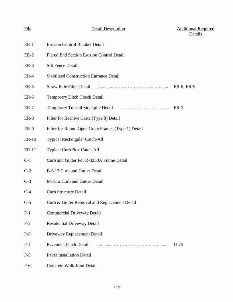
159
File Detail Description Additional Required
Details
ER-1 Erosion Control Blanket Detail
ER-2 Flared End Section Erosion Control Detail
ER-3 Silt Fence Detail
ER-4 Stabilized Construction Entrance Detail
ER-5 Straw Bale Filter Detail …............……………………..…........ ER-8, ER-9
ER-6 Temporary Ditch Check Detail
ER-7 Temporary Topsoil Stockpile Detail ………………………….. ER-3
ER-8 Filter for Beehive Grate (Type 8) Detail
ER-9 Filter for Round Open Grate Frames (Type 1) Detail
ER-10 Typical Rectangular Catch-All
ER-11 Typical Curb Box Catch-All
C-1 Curb and Gutter For R-3250A Frame Detail
C-2 B-6.12 Curb and Gutter Detail
C-3 M-3.12 Curb and Gutter Detail
C-4 Curb Structure Detail
C-5 Curb & Gutter Removal and Replacement Detail
P-1 Commercial Driveway Detail
P-2 Residential Driveway Detail
P-3 Driveway Replacement Detail
P-4 Pavement Patch Detail …............……………………..….......... U-25
P-5 Paver Installation Detail
P-6 Concrete Walk Joint Detail

160
File Detail Description Additional Required
Details
P-7 Grass Paver Installation Detail
P-8 Pavement Widening Detail
U-1 Structure Frame and Grate Adjustment Detail…………………….. U-2
U-2 Chimney Seal Detail
U-3 Sanitary Manhole Detail …............……………………..…........ U-1, U-2, U-5, U-23
U-4 Drop Manhole Detail …............……………………..…............ U-5
U-5 Pipe Connection To Structure Detail
U-6 Storm Manhole Detail …............……………………..…............ U-1, U-5
U-7 Storm Manhole With Restrictor Detail …............………………… U-1, U-5
U-8 Special Restrictor Storm Structure Detail
U-9 Catch Basin Detail …............……………………..…............…..... U-1, U-5
U-10 Type C Catch Basin Detail …............……………………..…............ U-1, U-5
U-11 Inlet Detail …............……………………..…............…………… U-1, U-5
U-12 Overflow (Weir) Structure Detail
U-13 Sump Pump Discharge Connection Detail
U-14 Storm Sewer Piping In "Unsewered Areas" Detail
U-15 Valve Vault Detail …............……………………..…......…............ U-1, U-5
U-16 Butterfly Valve Vault Detail …............……………………..….......... U-1, U-5
U-17 Pit-Set Meter Vault Detail …............……………………..…........... U-1, U-5
U-18 Pressure Connection Detail …............……………………..…......... U-1, U-5
U-19 Thrust Block Detail
U-20 Copper Water Service Connection Detail
U-21 Watermain Crossing Detail

161
File Detail Description Additional Required
Details
U-22 Hydrant Detail…………………………………………………………… U-19
U-23 Pipe Coupling Detail
U-24 Utility Trench In Non-Paved Areas-Detail
U-25 Utility Trench In Pavement Areas Detail …............………………… P-4
U-26 New Sewer Service Detail
U-27 Pipe Underdrain Detail
U-28 Casing Pipe Details
U-29 Storm Sewer Connection to Existing Pipe Detail
U-30 Sewer Service Replacement Detail …............……………………..…. U-23, U-26
U-31 Sewer Main and Sewer Service Replacement Detail ………...……..…. U-23, U-26
U-32 Water Service Replacement Detail #1…………………………………… U-20
U-33 Water Service Replacement Detail #2…………………………………… U-20
U-34 Trench HMA Paving Detail……………………………………… P-4
U-35
U-36
Auxiliary Box & Valve Detail
Dry Well Detail…………………………………………………………..
U-1
G-1 Lot Grading Detail
G-2 Legend and Abbreviations
G-3 Rain Garden Detail
G-4
G-5
Pipe Bollard Detail
Residential Street Light Detail (The Glen)

162

NOT TO SCALE
7"27"
1.5" CLEAR
BIT. SURFACE
CAP SCREW
2"
1.5" CLEAR
NOTES:
NOTES:
PROFILE VIEW
BACK OF CURB
B-6.18 CURB & GUTTER
2’ 2’
APPROX. 27" DIA
7"
18
"
3’ TRANSITION
GUTTER
NOTE:
PLAN VIEW
GUTTER TO MEET CURB, INLET, FRAME & GRATE
6"
12
"
VA
RIE
S
C-1
CURB & GUTTER
FOR R-3250A
FRAME DETAIL
R-3250A FRAME*
POSITION OF
INLET CASTING3- NO. 4 VERTICAL BARS
SPACED AT 1’-6" CENTERS
SYMETRICALLY ABOUT
CENTERLINE OF CASTING
3- NO. 4 REINFORCING
BARS 5’ IN LENGTH
CENTERED ABOUT
CENTERLINE OF CASTING
1- NO. 4 REINFORCING
BAR MUST GO THROUGH
LUG HOLE
1. CURB INLET CASTING SHALL BE FASTENED TEMPORARILY TO FRAME
CASTING WITH 2 CAP SCREWS, DURING CONSTRUCTION
2. CAP SCREWS MUST BE REMOVED AFTER CURB HAS HARDENED.
EXPANSION
JOINT
TOP OF CURB
TO TRANSITION
FROM 6" HIGH
TO 3" HIGH
COST OF ADDITIONAL GUTTER
TO MATCH DETAIL INCIDENTAL
3’ TRANSITION
TO 3" MOUNTABLE
CURB(TYP)
1. CURB CONTRACTOR TO VERIFY POSITION AND ELEVATION
OF FRAME AND GRATE PRIOR TO POUR. IF NOT CORRECT,
FIVE (5) FOOT TRANSITION AREA TO BE LEFT UNPOURED
UNTIL SITUATION IS CORRECTED BY CONTRACTOR.
* TYPE K GRATE (INSTALLED WITH VANES PERPENDICULAR
TO THE CURB) OR A R-2371 TYPE G GRATE.
4 1/4" 2 3/4"
REVISED:01-01-16

6"
4" 4"
NOTE:
NOT TO SCALE
R=3"
R=2"
12"
18"
%%130"
5"
3"
6"
DEPRESSED CURB
AT DRIVEWAYS,
SIDEWALK RAMP
AND WHERE
SHOWN ON PLANS
.
10
" M
IN
.
(V
AR
IE
S)
PROPOSEDPAVEMENT
10"
B-6.12
CURB & GUTTER
DETAIL
2-#4 EPOXY COATED BARS,
CONTINUOUS,AT UTILITY
TRENCH CROSSING,
EXCEPT ACROSS
EXPANSION JOINTS.
(SEE NOTE 5)
C-2
1.5" RISE AT DRIVEWAYS (6)
0.5" RISE AT SIDEWALK RAMPS
IDOT CA 6 CRUSHED
STONE BASE(4"MIN)
%%131"/FT
2-#6X18" LONG SMOOTH
EPOXY DOWEL BARS,
WITH GREASED CAPS AT
EXPANSION JOINTS.
(3/4" THICK BITUMINOUS
FILLED MATERIAL)
6" 6" 6"
1. 2" DEEP CONTRACTION JOINTS SHALL BE PLACED AT 15’ INTERVALS, AND
SHALL BE GROOVED WITH AN EDGING TOOL. SEE ARTICLES 420.05 AND 606
OF IDOT STANDARD SPECIFICATIONS.
2. EXPANSION JOINTS SHALL BE PLACED AT 60’ (MAX) INTERVALS, AT ALL
P.C.’S AND P.T.’S, CURB RETURNS, AND AT THE END OF EACH POUR.
3. P.C.C. SHALL CONSIST OF IDOT CLASS SI CONCRETE MIX, WITH 5% TO 8%
AIR ENTRAINMENT, AND A MINIMUM COMPRESSIVE STRENGTH OF 3,500
PSI AT 14 DAYS.
4. PROVIDE 2 #4X18" EPOXY COATED TIE BARS AT CONNECTIONS BETWEEN EXISTING
AND NEW CURB & GUTTER.
5. CURBS, SPANNING UTILITY TRENCHES, SHALL BE CONSTRUCTED WITH TWO
#4 REINFORCEMENT BARS,WHICH EXTEND FIVE (5) FEET BEYOND THE
TRENCH WALLS.
6. WHERE DRIVEWAYS ARE INTENDED FOR PEDESTRIAN ACCESS, RISE SHALL
BE 0.5".
REVISED:01-01-16

12"
5"
12"
DEPRESSED CURB
MOUNTABLE CURB
4"10"
NOTE:
NOT TO SCALE
.
.
6"
1.5" AT DRIVEWAYS
0.5" AT SIDEWALK RAMPS
4"
6"
PROPOSED
PAVEMENT %%130"
3"R
2 #4 EPOXY COATED BARS,
CONTINUOUS,AT UTILITY
TRENCH CROSSING,
EXCEPT ACROSS
EXPANSION JOINTS.
(SEE NOTE 5)
2 #4 EPOXY COATED BARS,
CONTINUOUS AT UTILITY
TRENCH CROSSING,
EXCEPT ACROSS
EXPANSION JOINTS.
(SEE NOTE 5)
PROPOSED
PAVEMENT %%130"
10" MIN.
10" MIN.
C-3
M-3.12
CURB & GUTTER
DETAIL
IDOT CA 6 CRUSHED
STONE BASE (4" MIN)
IDOT CA 6 CRUSHED
STONE BASE (4" MIN)
%%131"/FT
6" 6" 6"
6" 6" 6"
4" 10" 4"
3"
5"3"
%%131"/FT
2 #6X18" LONG SMOOTH
EPOXY DOWEL BARS, WITH
GREASED CAPS AT
EXPANSION JOINTS.
3"
2 #6X18" LONG SMOOTH EPOXY
DOWEL BARS, WITH GREASED
CAPS AT EXPANSION JOINTS.
1. 2" DEEP CONTRACTION JOINTS SHALL BE PLACED AT 15’ INTERVALS, AND
SHALL BE GROOVED WITH AN EDGING TOOL. SEE ARTICLES 420.05 AND 606
OF IDOT STANDARD SPECIFICATIONS.
2. EXPANSION JOINTS SHALL BE PLACED AT 60’ (MAX) INTERVALS, AT ALL
P.C.’S AND P.T.’S, CURB RETURNS, AND AT THE END OF EACH POUR.
3. P.C.C. SHALL CONSIST OF IDOT CLASS SI CONCRETE MIX, WITH 5% TO 8%
AIR ENTRAINMENT, AND A MINIMUM COMPRESSIVE
STRENGTH OF 3,500 PSI AT 14 DAYS.
4. PROVIDE 2 #4X18" EPOXY COATED TIE BARS AT CONNECTIONS BETWEEN EXISTING
AND NEW CURB & GUTTER.
5. CURBS, SPANNING UTILITY TRENCHES, SHALL BE
CONSTRUCTED WITH TWO #4 REINFORCEMENT BARS,
WHICH EXTEND FIVE (5) FEET BEYOND THE TRENCH
WALLS. REVISED:01-01-16
3"R
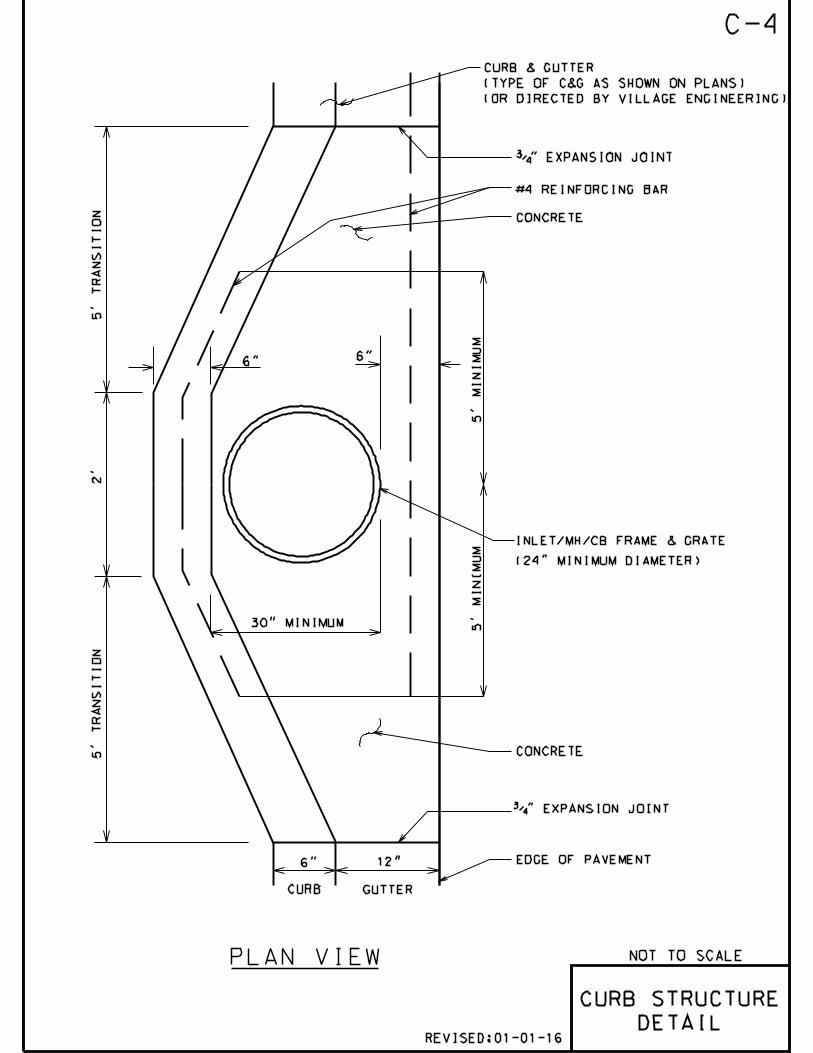
~
~
~NOT TO SCALE
5’
MIN
IMU
M
12"6"
5’ T
RA
NS
IT
IO
N
30" MINIMUM
EDGE OF PAVEMENT
CONCRETE
INLET/MH/CB FRAME & GRATE
(24" MINIMUM DIAMETER)
5’ T
RA
NS
IT
IO
N
6"
CONCRETE
5’
MIN
IMU
M
2’
6"
C-4
CURB & GUTTER
(TYPE OF C&G AS SHOWN ON PLANS)
(OR DIRECTED BY VILLAGE ENGINEERING)
#4 REINFORCING BAR
CURB GUTTER
PLAN VIEW
CURB STRUCTURE
DETAIL
%%131" EXPANSION JOINT
%%131" EXPANSION JOINT
REVISED:01-01-16

4"HOT-MIX ASPHALT SURFACE
REMOVAL (THICKNESS VARIES)
EXISTING GRANULAR BASE
EXISTING CONDITIONS
EXISTING GRANULAR BASE
INTERMEDIATE CONDITIONS
FINAL CONDITIONS
EXISTING GRANULAR BASE
RE-SAWCUT ANY DAMAGED PAVEMENT
EDGE TO PROVIDE A CLEAN STRAIGHT
EDGE FOR HOT-MIX ASPHALT BINDER
MATERIAL PLACEMENT.
RE-SAWCUT LINE**
PROPOSED 6" HIGH FORM (FOR B6.12 CURB),
PROPOSED 4" HIGH FORM (FOR M3.12 CURB)
*
**
CURB & GUTTER SHALL BE SAWCUT
(FULL DEPTH) PRIOR TO CURB &
GUTTER SECTION REMOVAL FOR
REPLACEMENT.
EXISTING (REMAINING)
HOT-MIX ASPHALT
PROPOSED FULL DEPTH PAVEMENT
SAW CUT LINE
SECTION OF EXISTING
CURB & GUTTER TO BE
REMOVED* AND
REPLACED
C-5
CURB & GUTTER
REMOVAL AND
REPLACEMENT
DETAIL
NOT TO SCALE
EXISTING HOT-MIX ASPHALT BINDER
(THICKNESS VARIES)
REPLACEMENT
CURB & GUTTER
REPLACEMENT
CURB & GUTTER
HOT-MIX ASPHALT BINDER
TO REMAIN
EXISTING (REMAINING)
HOT-MIX ASPHALT BINDER
HOT-MIX ASPHALT
SURFACE COURSE
(NEW) HOT-MIX ASPHALT
BINDER MATERIAL
FILL EXISTING WEDGE WITH PCC. PCC SHALL
BE THE SAME MIX USED FOR CURB AND GUTTER.
COST IS INCIDENTAL TO CURB REPLACEMENT
WORK.
REVISED:01-01-16

NOT TO SCALE
EROSION
CONTROL
BLANKET
DETAIL
NOTES:
SLOPE INSTALLATION
FLOW
DIRECTION
1. PREPARE SOIL BEFORE INSTALLING BLANKETS, INCLUDING APPLICATION
OF LIME, FERTILIZER, AND SEED.
2. BEGIN AT THE TOP OF THE SLOPE (OR CHANNEL) BY ANCHORING THE
BLANKET IN A 6" DEEP X 6" WIDE TRENCH. BACKFILL AND COMPACT
THE TRENCH AFTER STAPLING.
3. ROLL THE BLANKETS DOWN (STARTING AT DOWNSTREAM PROCEEDING
UPSTREAM) HORIZONTALLY ACROSS THE SLOPE.
4. THE EDGES OF PARALLEL BLANKETS MUST BE STAPLED WITH AN
APPROXIMATE (MIN) 4" OVERLAP.
5. WHEN BLANKETS MUST BE SPLICED DOWN THE SLOPE, PLACE
BLANKETS END OVER END (SHINGLE STYLE) WITH APPROXIMATELY A
(MIN) 6" OVERLAP. USE A DOUBLE ROW OF STAGGERED STAPLES
4" APART TO SECURE BLANKETS.
6. IN HIGH FLOW CHANNEL APPLICATIONS, A STAPLE CHECK SLOT IS
RECOMMENDED AT 30 TO 40 FOOT INTERVALS. USE A ROW OF STAPLES
4" APART OVER ENTIRE WIDTH OF THE CHANNEL. PLACE A SECOND
ROW 4" BELOW THE FIRST ROW IN A STAGGERED PATTERN.
7. THE TERMINAL END OF THE BLANKETS MUST BE ANCHORED IN A
6" DEEP X 6" WIDE TRENCH. BACKFILL AND COMPACT THE TRENCH
AFTER STAPLING.
ER-1
REVISED:01-01-16

NOT TO SCALE
FLARED END
SECTION
EROSION
CONTROL
DETAIL
FLOWNOTES:
ER-2
JOIN THE ENDS TOGETHER
WITH COIR TWINE
(TYPICAL)
SEE NOTE 3
ANGLE STAKES,
BUTT TIGHTLY
ADJACENT LOGS
STAKES (3.0’ O.C.)
TO PENETRATE 6" TO
12" BELOW GRADE
(SEE NOTE 3)
EXISTING FLARED
END SECTION
%%
p3.0
’
3.0’O.C.
MAXIMUM
SEDIMENT BARRIER
(SEE NOTE 1)
1. COIR LOGS, GRAVEL BAGS (OR APPROVED BY THE ENGINEER
EQUAL) EROSION CONTROL AND SEDIMENT BARRIER MATERIAL
SHALL BE USED.
2. SEDIMENT BARRIERS SHALL BE PLACED WITH ENDS TIGHTLY
ABUTTING THE ADJACENT SEDIMENT BARRIERS TO CREATE
A CONTINUOUS BARRIER.
3. WOODEN WEDGES AND/OR STAPLES AS PER MANUFACTURER’S
PRODUCT SPECIFICATIONS MAY BE USED FOR SEDIMENT BARRIER
STABILIZATION.
4. INSPECTION OF SEDIMENT BARRIERS SHALL BE AT LEAST ONCE
PER WEEK AND AFTER RAIN EVENTS IN EXCESS OF HALF INCH ( 12")
PER DAY OR EQUAL SNOW MELT. REPAIR OR REPLACEMENT OF
SEDIMENT BARRIER SHALL BE MADE PROMPTLY AS NEEDED.
5. REMOVE ACCUMULATED SEDIMENT WHEN SEDIMENT DEPTH AT
THE BARRIER IS APPROXIMATELY EQUAL TO ONE-HALF OF
BARRIERS HEIGHT.
6. SEDIMENT BARRIERS SHALL BE REMOVED UPON COMPLETION
OF CONSTRUCTION AND ONLY WHEN DIRECTED BY VILLAGE
ENGINEERING.
REVISED:01-01-16

NOTES:
COMPACTED BACKFILL
FLOW
NATURAL SOIL
2’-0"
(M
IN
.)
SILT FENCE
DETAIL
ER-3
NOT TO SCALE
FA
BR
IC
2’0
" M
IN
.
PO
ST
S 4
’0" M
IN
.
(4
.0
’ O
.C
.)
MIN. 6"x6" TRENCH
(USAGE OF SLICING METHOD
IS RECOMMENDED FOR
FABRIC TOE INSTALLATION)
EXTEND GEOTEXTILE FABRIC
INTO TRENCH A MINIMUM OF 6"
VERTICALLY AND 6" HORIZONTALLY
WOOD (2"x2") OR STEEL
(1.33 LBS/FT) POSTS
AT 4’ MAX. SPACING
1. SILT FENCE SHALL BE PLACED AT LOCATIONS SHOWN
ON THE PLANS AND WHERE INDICATED BY VILLAGE ENGINEERING.
2. ATTACH GEOTEXTILE FABRIC TO WIRE MESH WITH HOG RINGS, TO WOOD POSTS
WITH NAILS, AND TO STEEL POSTS WITH TIE-WIRES AT TOP AND MID-SECTION.
3. OVERLAP GEOTEXTILE FABRIC BY 6" AND FOLD WHERE 2 SECTIONS ADJOIN.
4. INSPECTION OF SILT FENCES SHALL BE AT LEAST ONCE PER
WEEK AND AFTER RAIN EVENTS IN EXCESS OF HALF INCH ( 12") PER DAY OR EQUAL
SNOW MELT. REPAIR OR REPLACEMENT OF SILT FENCE SHALL BE MADE PROMPTLY
AS NEEDED.
5. SEDIMENT TRAPPED BY THE SILT FENCE SHALL BE REMOVED (AND
PROMPTLY DISPOSED OF) WHENEVER SEDIMENT ACCUMULATION DEPTH AT THE
SILT FENCE IS APPROXIMATELY EQUAL TO TWELVE (12) INCHES (ONE-HALF OF
SILT FENCE HEIGHT).
6. MATERIAL (GEOTEXTILE & POST) INSTALLATION, MAINTENANCE, AND SILT FENCE
REMOVAL SHALL COMPLY WITH AASHTO, M 288 REQUIREMENTS.
7. THE FABRIC FOR SILT FENCE SHALL BE A WOVEN FABRIC MEETING THE
REQUIREMENTS OF AASHTO M 288 (TABLE 7) FOR UNSUPPORTED SILT FENCE
WITH LESS THAN 50 PERCENT GEOTEXTILE ELONGATION.
8. SILT FENCE SHALL BE MAINTAINED IN PLACE UNTIL COMPLETION OF
CONSTRUCTION AND THE UPSLOPE AREA HAS BEEN STABILIZED,
AND SHALL BE REMOVED ONLY WHEN DIRECTED BY VILLAGE ENGINEERING.
GEOTEXTILE FABRIC
(SEE NOTE 7)
REVISED:01-01-16

NOT TO SCALE
STABILIZED
CONSTRUCTION
ENTRANCE
DETAIL
10’ MIN
10
’
MIN
10
’
MIN
EXISTING
GROUND 100’ MIN
COARSE AGGREGATE
SILT FENCE
EXISTING
PAVEMENT
PLAN
EXISTING
GROUND
100’ MIN6" M
IN
24
" M
IN
FILTER FABRIC
ELEVATION
MOUNTABLE BERM
(TIED INTO SILT FENCE)
A
A
30’ MIN
FILTER FABRIC
TO EXTEND FULL WIDTH OF ENTRANCE
PREPARED SUBGRADE
3" MIN
3" MIN
SECTION A-A
NOTES:
30
’
MIN
5:1 SLOPE
(TYP)
EXISTING
PAVEMENT
EXISTING
GROUND
1. GEOTEXTILE FILTER FABRIC SHALL BE PLACED OVER THE
CLEARED AREA PRIOR TO PLACING COARSE AGGREGATE
2. COARSE AGGREGATE (OR CRUSHED CONCRETE) SHALL MEET
IDOT GRADATION FOR CA-1 CRUSHED AGGREGATE.
3. STABILIZED CONSTRUCTION ENTRANCE SHALL BE INSTALLED,
PRIOR TO ONSET OF CONSTRUCTION OPERATIONS AND SHALL
BE MAINTAINED THROUGHOUT THE PROJECT.
4. CONSTRUCTION ENTRANCE SHALL BE REMOVED UPON
COMPLETION OF CONSTRUCTION AND ONLY WHEN
DIRECTED BY VILLAGE ENGINEERING.
ER-4
REVISED:01-01-16

NOT TO SCALE
NOTES:
ER-5
INSTALL SEDIMENT FILTER
BASKET BELOW GRATE
TO PREVENT SILT FROM
ENTERING DRAINAGE
STRUCTURE (SEE NOTE 5)
JOIN THE ENDS TOGETHER
WITH COIR TWINE
5. REINFORCED FILTER BASKETS SHALL BE USED FOR SEDIMENT
CONTROL. SEE STANDARD DETAILS ER-8, ER-9.
8. SEDIMENT BARRIERS AND FILTER BASKETS SHALL BE REMOVED UPON
COMPLETION OF CONSTRUCTION AND ONLY WHEN DIRECTED
BY VILLAGE ENGINEERING.
SEE NOTE 4
(TYPICAL)
STAPLE
WOODEN WEDGE
EXISTING INLET OR
CATCH BASIN GRATE
4. WOODEN WEDGES AND/OR STAPLES AS PER MANUFACTURER’S PRODUCT
INSTALLATION SPECIFICATIONS.
6. INSPECTION OF SEDIMENT BARRIERS AND FILTER BASKETS SHALL
BE AT LEAST ONCE PER WEEK AND AFTER RAIN EVENTS IN EXCESS
OF HALF INCH ( 12") PER DAY OR EQUAL SNOW MELT.
REPAIR OR REPLACEMENT OF SEDIMENT FILTER SHALL BE MADE
PROMPTLY AS NEEDED.
ABOVE
GRADE INLET
FILTERS
7. REMOVE ACCUMULATED SEDIMENT WHEN SEDIMENT DEPTH AT THE FILTER
BARRIER IS APPROXIMATELY EQUAL TO ONE-HALF OF BARRIER’S HEIGHT.
SEDIMENT FILTER BARRIER -
COIR LOGS 9" DIAMETER,
%%p20’ LONG
%%p2"
1. SEDIMENT FILTER BARRIERS (COIR LOGS OR APPROVED EQUAL) AND
FILTER BASKETS SHALL BE INSTALLED AND MAINTAINED FOR ALL
STORM SEWER INLETS, CATCH BASINS AND MANHOLES WITH OPEN GRATES,
AS DIRECTED BY VILLAGE ENGINEERING.
2. SEDIMENT FILTER BARRIERS SHALL BE PLACED WITH ENDS TIGHTLY ABUTTING
THE ADJACENT SEDIMENT BARRIERS TO CREATE A CONTINUOUS BARRIER.
3. EACH SEDIMENT BARRIER SHALL BE STAPLED (3.0’ O.C.). STAPLES
TO PENETRATE 6" TO 12" BELOW GRADE.
REVISED:01-01-16

NOT TO SCALE
TEMPORARY
DITCH CHECK
DETAIL
AAB
SPACING BETWEEN TEMPORARY DITCH CHECKS
A BL
NOTES:
ER-6
POINTS A SHOULD NOT BE
HIGHER THAN POINT B
U-SHAPED WIRE
STAPLES
SECTION 1-1
PLACEMENT OF SILT DIKES IN DRAINAGEWAY
APRON w/ STAPLES
C
1
1
ANGLE STAPLES,
BUTT TIGHTLY
ADJACENT DITCH
CHECK SECTIONS
DITCH CHECK
SEE NOTE 1
3.0’O.C. MAXIMUM
DITCH CHECK
(TRIANGULAR SILT
DIKE BARRIER -
SEE NOTE 1)
L= THE DISTANCE SUCH THAT POINTS
A AND B ARE OF EQUAL ELEVATION
STAPLES
COMPACTED
BACKFILL
1. COIR LOGS, GEORIDGE OR SEDIMENT STOP FILTRATION
SYSTEM MAY BE USED IN LIEU OF TRIANGULAR SILT
DIKE BARRIER IF APPROVED BY THE ENGINEER.
2. INSPECTION OF SILT DIKES SHALL BE AT LEAST ONCE
PER WEEK AND AFTER RAIN EVENTS IN EXCESS OF HALF
INCH ( 12") PER DAY OR EQUAL SNOW MELT. REPAIR OR
REPLACEMENT OF DITCH CHECK SHALL BE MADE PROMPTLY
AS NEEDED.
3. REMOVE SEDIMENT WHEN SEDIMENT DEPTH AT THE DITCH
CHECK IS APPROXIMATELY EQUAL TO ONE-HALF OF DIKE’S
HEIGHT (0.5C).
4. SILT DIKES SHALL BE REMOVED UPON COMPLETION OF
CONSTRUCTION AND ONLY WHEN DIRECTED BY THE VILLAGE
ENGINEERING.
4" TRENCH
(TYP.)
REVISED:01-01-16

NOT TO SCALE
TEMPORARY
TOPSOIL
STOCKPILE
DETAIL
SILT FENCE TO EXTEND
AROUND ENTIRE PERIMETER OF
TOPSOIL STOCKPILE, OR TO
EXTEND AROUND DOWNSTREAM
PORTION IF STOCKPILE IS ON SLOPE.
TOPSOIL
STOCKPILE
ORIGINAL GROUND SURFACE
10"
NOTES:
(TYP)
ER-7
SILT FENCE
(SEE DETAIL
ER-3)
CHAIN LINK FENCE
(SEE NOTE 7)
1. AN ON-SITE DRAINAGE SWALE SHALL BE LOCATED BETWEEN THE TOPSOIL
STOCKPILE AND OFF-SITE PROPERTY.
2. REFERENCE IS MADE TO THE SILT FENCE DETAIL (ER-3) FOR MATERIALS
AND INSTALLATION METHODS.
3. IF THE STOCKPILE IS TO REMAIN FOR MORE THAN 14 DAYS, IT SHALL BE
STABILIZED WITH STRAW BLANKET OR SEEDED TO MINIMIZE EROSION.
4. INSPECTION OF SILT FENCES SHALL BE AT LEAST ONCE PER WEEK
AND AFTER RAIN EVENTS IN EXCESS OF HALF INCH (1/2 ") PER DAY OR
EQUAL SNOW MELT. REPAIR OR REPLACEMENT OF SILT FENCE SHALL BE
MADE PROMPTLY AS NEEDED.
5. SEDIMENT TRAPPED BY THE SILT FENCES SHALL BE REMOVED AND PROPERLY
DISPOSED OF WHENEVER SEDIMENT ACCUMULATION DEPTH AT THE SILT FENCE
IS APPROXIMATELY EQUAL TO TWELVE (12) INCHES (ONE-HALF OF SILT
FENCE HEIGHT).
6. SILT FENCES SHALL BE MAINTAINED IN PLACE UNTIL TOPSOIL STOCKPILE
HAS BEEN ELIMINATED AND SHALL BE REMOVED ONLY WHEN DIRECTED
BY VILLAGE ENGINEERING.
7. TO COMPLY WITH THE VILLAGE’S SAFETY REQUIREMENTS ERECTION OF
STABLE AND SECURE SIX (6) FEET HIGH CHAIN LINK FENCE AROUND THE
PERIMETER OF THE STOCKPILED MATERIAL IS REQUIRED. COORDINATE
WITH THE ENGINEER.
REVISED:01-01-16
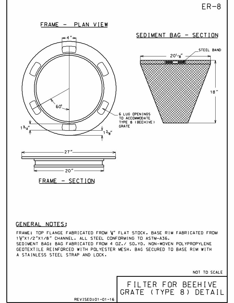
4"
600
1%%131"
1%%133"
27"
20"
20%%132"
18"
NOT TO SCALE
FRAME: TOP FLANGE FABRICATED FROM 18" FLAT STOCK. BASE RIM FABRICATED FROM
112"X1/2"X1/8" CHANNEL. ALL STEEL CONFORMING TO ASTM-A36.
SEDIMENT BAG: BAG FABRICATED FROM 4 OZ./ SQ.YD. NON-WOVEN POLYPROPYLENE
GEOTEXTILE REINFORCED WITH POLYESTER MESH. BAG SECURED TO BASE RIM WITH
A STAINLESS STEEL STRAP AND LOCK.
6 LUG OPENINGS
TO ACCOMMODATE
TYPE 8 (BEEHIVE)
GRATE
SEDIMENT BAG - SECTION
STEEL BAND
FRAME - PLAN VIEW
FRAME - SECTION
ER-8
GENERAL NOTES:
FILTER FOR BEEHIVE
GRATE (TYPE 8) DETAIL REVISED:01-01-16

2"
20"
18"11%%132"
22%%130"
19%%135"
NOT TO SCALE
STEEL BAND
SEDIMENT BAG - SECTIONFRAME - PLAN VIEW
FRAME - SECTION
ER-9
GENERAL NOTES:
FILTER FOR ROUND
OPEN (TYPE 1)
GRATE & FRAME DETAIL
FRAME: TOP FLANGE FABRICATED FROM 1 14"X1 14"X1/8" ANGLE. BASE RIM FABRICATED
FROM 1 12"X1/2"X1/8" CHANNEL. HANDLES AND SUSPENSION BRACKETS FABRICATED
FROM 1 14"X1/4" FLAT STOCK. ALL STEEL CONFORMING TO ASTM-A36.
SEDIMENT BAG: BAG FABRICATED FROM 4 OZ./ SQ.YD. NON-WOVEN POLYPROPYLENE
GEOTEXTILE REINFORCED WITH POLYESTER MESH. BAG SECURED TO BASE RIM WITH
A STAINLESS STEEL STRAP AND LOCK.
FILTER FOR OTHER SHAPE GRATES SHALL BE APPROVED IN ADVANCE OF PLACEMENT
BY VILLAGE ENGINEERING.
REVISED:01-01-16
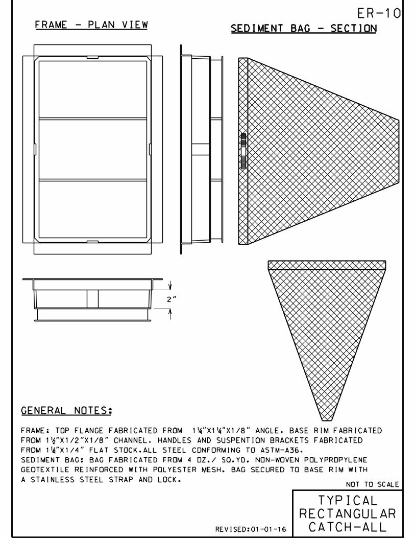
NOT TO SCALE
SEDIMENT BAG - SECTIONFRAME - PLAN VIEW
FRAME: TOP FLANGE FABRICATED FROM 1 14"X1 14"X1/8" ANGLE. BASE RIM FABRICATED
FROM 1 12"X1/2"X1/8" CHANNEL. HANDLES AND SUSPENTION BRACKETS FABRICATED
FROM 1 14"X1/4" FLAT STOCK.ALL STEEL CONFORMING TO ASTM-A36.
SEDIMENT BAG: BAG FABRICATED FROM 4 OZ./ SQ.YD. NON-WOVEN POLYPROPYLENE
GEOTEXTILE REINFORCED WITH POLYESTER MESH. BAG SECURED TO BASE RIM WITH
A STAINLESS STEEL STRAP AND LOCK.
SEDIMENT BAG - SECTION
GENERAL NOTES:
TYPICAL
RECTANGULAR
CATCH-ALL
2"
ER-10
REVISED:01-01-16

NOT TO SCALE
SEDIMENT BAG - SECTIONFRAME - PLAN VIEW
FRAME: TOP FLANGE FABRICATED FROM 1 14"X1 14"X1/8" ANGLE. BASE RIM FABRICATED
FROM 1 12"X1/2"X1/8" CHANNEL. HANDLES AND SUSPENTION BRACKETS FABRICATED
FROM 1 14"X1/4" FLAT STOCK.ALL STEEL CONFORMING TO ASTM-A36.
SEDIMENT BAG: BAG FABRICATED FROM 4 OZ./ SQ.YD. NON-WOVEN POLYPROPYLENE
GEOTEXTILE REINFORCED WITH POLYESTER MESH. BAG SECURED TO BASE RIM WITH
A STAINLESS STEEL STRAP AND LOCK.
SEDIMENT BAG - SECTION
GENERAL NOTES:
2"
ER-11
FABRIC FLAP TO
COVER CURB BOX
TYPICAL
CURB BOX
CATCH-ALL REVISED:01-01-16

5’ TO 10’ (TYP.)
PUBLIC UTILITY
EASEMENT
RECOMMENDED
USABLE
REAR YARD AREA
FRONT YARDDR
IVE
WA
Y
IF THE BUILDING IS MULTI-LEVEL, SHOW PROPOSED TOP OF
FOUNDATION AND FINISHED GRADE AT ALL LEVELS.
*STREET FINISHED
GRADE =T/F MINUS
0.33’-0.66’
*
SWALE-1.0% MIN.
MIN
. SW
AL
E-1
.0%M
IN.
SW
AL
E-1
.0%
4:1
MA
X.
1%
MIN
.
20
’ M
IN.
1%
MIN
.
8%
MA
X.
1%
MIN
.
4:1
MAX.
1%
MIN.
4:1
MAX.
1%
MIN.30’ T
O 6
0’ (
TY
P.)
1%
MIN
.
TOP OF FOUNDATION =
NO LESS THAN AVERAGE
OF ADJACENT SIDE LOTS
G-1
NOT TO SCALE
LOT GRADING
DETAIL REVISED:01-01-16

EXISTING EXISTING
N
NOTE:
PROPOSED PROPOSED
LEGEND & ABBREVIATIONS
RIGHT OF WAY (ROW)
ASPH ASPHALT
FC FRAME & COVER
AR ADJUSTING RINGS
CFC CONCRETE DR. FAIR CONDITION
CPC CONCRETE DR. POOR CONDITION
BGC BITUMINOUS DR. GOOD CONDITION
CONC, PCC CONCRETE
FV FIELD VERIFY
CGC CONCRETE DR. GOOD CONDITION
BFC BITUMINOUS DR. FAIR CONDITION
BPC BITUMINOUS DR. POOR CONDITION
BRP BRICK PAVER
NW NO WORK
EOP EDGE OF PAVEMENT
B-B BACK OF CURB TO BACK OF CURB
AR&FC ADJUSTING RINGS & FRAME & COVER
BENCHMARK (BM)
R&R STRUCTURE TO BE REM.& REP.
ADJ STRUCTURE TO BE ADJUSTED
R STRUCTURE TO BE REMOVED
CABLE LINE
E-E EDGE OF PAVEMENT TO EDGE OF PAV
COMMUNICATIONS TOWER
ELECTRIC CONTROLLER
ELECTRIC LINE
ELECTRIC MANHOLE
ELECTRIC POLE
ELECTRIC TRANSFORMER
FENCE
FIBER OPTIC CABLE
GUARDRAIL
GAS LINE
GAS VALVE
IRON PIPE
MAIL BOX
MONUMENT
RAILROAD TRACKS
RAILROAD CROSSING GATE
PAVEMENT MARKING
PAVEMENT MARKING
PAVEMENT MARKING
PAVEMENT MARKING
PAVEMENT MARKING
PAVEMENT MARKING
ROAD SIGN
ROAD SIGN
ROAD SIGN
ROAD SIGN
ROAD SIGN
ROAD SIGN
ROAD SIGN
BIKE PATH ELEVATION
BIKE ROUTE ELEVATION
SIDEWALK ELEVATIONS
SIGN
SILO
SILT FENCE
SPOT ELEVATION
SIGN TYPE
STREET LIGHT CABINET
STREET LIGHT CONTROLER
STREET LIGHT HAND HOLE
STREET LIGHT POWER POLE
STREET LIGHT
TANK
TELEPHONE CONTROLLER
TELEPHONE LINE
TELEPHONE MANHOLE
TELEPHONE POLE
TRAFFIC SIGNAL CONTROLLER
TRAFFIC SIGNAL HAND HOLE
TRAFFIC SIGNAL
TRAFFIC SIGNAL POLE
CONIFER TREE
DECIDUOUS TREE
WATER MAIN
WATER MAIN CAP-PLUG
WATER MAIN B-BOX
WATER MAIN HYDRANT
WATER MAIN METER PIT
WATER MAIN VALVE-VAULT
WATER IRRIGATION
SANITARY LIFT STATION
SANITARY SEWER (SANS)
SANITARY MANHOLE (SMH)
SANITARY CAP-PLUG
SANITARY MWRD
SANITARY CLEAN OUT (CO)
SANITARY SERVICE
SANITARY MANHOLE MWRD
WATER MAIN SERVICE
STORM LIFT STATION
STORM INLET (INL)
STORM SEWER (SS)
STORM CAP-PLUG
STORM MANHOLE (STMH)
STORM CATCH BASIN (CB)
STORM UNDERDRAIN
STORM SERVICE
STORM CLEAN OUT (CO)
STORM RESTRICTOR
STORM SWALE
STORM CULVERT
STORM HEADWALL
STATIONS
WATER MAIN ABANDONED
SANITARY ABANDONED
STORM ABANDONED
STORM FLARED END SECTION (FES)
100.0 CONTOUR
N ARROWTR SIGNAL VEHICLE DETECTOR
SEWER SECTION TO BE REPLACED.
DISTANCES ARE MEASURED FROM
THE UPSTREAM MANHOLE
DRIVEWAY ELEVATION
BUSH OR SHRUB
BUSH OR SHRUB #2
ROAD BACK OF CURB
ROAD FACE OF CURB
ROAD EDGE OF PAVEMENT
ROAD CENTERLINE
FLOW LINE
STREET LIGHT CONDUIT
HANDICAP
IDOT STANDARD 000001(LATEST EDITION) SHALL BE USED FOR
STANDARD SYMBOLS & ABBREVIATIONS NOT INDICATED ON THIS SHEET
G-2
100.0
10 25
CL
CT
E
TR
FOC
G
GV
IP
ONE WAY
S
SF
SLC
TANK
T
ROW
E
TR
ONE WAY
SF
SLCSLC
MPMP
LS LS
LS LS
RR
WATER MAIN VALVE AUX BOX
Revised:01-01-2011

NOT TO SCALE
%%p 20’
%
%p 10’
SEE NATIVE
PLANTING LIST
PLAN VIEW
CROSS SECTION
SHEET FLOW &
WATER SOURCE
OVERFLOW
(TOWARDS
STREET OR
DRAINAGE
WAY)
TOP SOIL
TOP SOIL &
SAND MIX
6"
12"
POOLING
ZONE
FILTRATION
ZONE
RECHARGE
ZONE
GRAVEL
WATER
SOURCE
AT GRADE
(SUMP OR
DOWNSPOUT)
UNDERDRAIN (6") IN
PERMEABLE FABRIC
CONNECTED TO STORM
WATER SYSTEM
(OPTIONAL)
18"M
IN
12"M
IN
RAIN GARDEN
DETAIL
6"
MIN
G-3
REVISED:01-01-16
SEE ENGINEERING STANDARDS
MANUAL SECTION F. FOR
REQUIREMENTS AND APPROVED
NATIVE PLANTING LIST

ALL PIPES SHALL BE PAINTED TRAFFIC YELLOW
NOTE:
3" MIN
PAVEMENT OR
FINISHED GRADE
FILL POST
WITH CONCRETE
2500 PSI P.C.
CONCRETE MINIMUM
(TYP.)
6" SCH. 40 STEEL PIPE
FILLED WITH CONCRETE
WITH TOP ROUNDED
1.5’
8’
4’
3"
PIPE
BOLLARD
DETAIL
G-4
REVISED:01-01-16

NOT TO SCALE
BETWEEN DRIVES AT CORNER
CURB CURB
16’ MIN.ON SIDE STREET
30’ MIN. ON MAIN THOROUGHFARE
8’ MIN. IF CROSS STREET IS
A SIDE STREET
15’ MIN. IF CROSS STREET
IS A MAIN THOROUGHFARE
PROPERTY LINE PROPERTY LINE
DRIVEWAY LOCATION AND SPACING
CONCRETE DRIVEWAYS
ASPHALT DRIVEWAYS
DRIVEWAY WIDTHS
WIDTH OF DRIVEWAY 35’ MAXIMUM
WIDTH OF FLARE 41’ MAXIMUM AT CURB LINE
NUMBER OF ENTRANCES AND EXITS
NOTE:
NO DRIVEWAY SHALL BE CONSTRUCTED SO AS
TO GO THROUGH OR INTERFERE
WITH EXISTING SIDEWALK.
COMMERCIAL
DRIVEWAY
DETAIL
APPROACH 4" BITUMINOUS ASPHALT CONCRETE
8" (MIN) IDOT CA 6 CRUSHED STONE
DRIVEWAY 4" BITUMINOUS ASPHALT CONCRETE
6" (MIN) IDOT CA 6 CRUSHED STONE
APRON 8" PORTLAND CEMENT CONCRETE
4" (MIN) IDOT CA 6 CRUSHED STONE
DRIVEWAY 6" PORTLAND CEMENT CONCRETE
4" (MIN. IDOT CA 6 CRUSHED STONE
P-1
THE VILLAGE RESERVES THE RIGHT TO ESTABLISH A MAXIMUM NUMBER OF EXIT AND
ENTRANCE LANES BASED UPON THE PARKING CAPACITY AND TRAFFIC HAZARDS THEY
CREATE IN THE PUBLIC STREETS.
REVISED:01-01-16

VARIES PER ENGINEER
STREET
MAX WIDTH 30 FEET
1’
PARKWAY
VARIES
3’ MAX 3’ MAX
NOT TO SCALE
DEPRESSED
CURB
ROW LINE
SAWCUT
EXISTING
CURB,
IF PRESENT
(TYP.)
NEW P.C.C. SIDEWALK 6" THICK
CONTRACTION JOINT
(SEE NOTE 2)
NOTES:
DRIVEWAY
WITHIN DRIVEWAY AREA
APRON AREA
RESIDENTIAL
DRIVEWAY
DETAIL
EXISTING
OR NEW
P.C.C.
SIDEWALK
5" THICK
P-2
1/2" PREFORMED
EXPANSION JOINT
2-1 1/4"x19" EPOXY
COATED DOWELS
DRILLED AND
EMBEDDED 9"
INTO EXISTING
CURB (TYP)
1. FOR P.C.C. DRIVEWAY OVER AN UNDERGROUND UTILITY TRENCH, PLACE
6’ X 6’ - W2.9XW2.9 WELD AND WIRE FABRIC AT MID-DEPTH OF THE
CONCRETE.
2. FOR CONCRETE APRON WIDER THAN 16’, A CONTRACTION JOINT SHALL BE
LOCATED ALONG THE CENTERLINE.
3. P.C.C. CONCRETE DRIVEWAYS:
APRON- 6" (MIN) PORTLAND CEMENT CONCRETE AND
4" (MIN) IDOT CA 6 CRUSHED STONE
DRIVEWAY- 4" (MIN) PORTLAND CEMENT CONCRETE AND
4" (MIN) IDOT CA 6 CRUSHED STONE
4. BITUMINOUS DRIVEWAYS:
APRON- 3" (MIN) BITUMINOUS CONCRETE SURFACE COURSE AND
6" (MIN) IDOT CA 6 CRUSHED STONE
DRIVEWAY- 3" (MIN) BITUMINOUS CONCRETE SURFACE COURSE AND
4" (MIN) IDOT CA 6 CRUSHED STONE
5. BRICK PAVERS AND OTHER ARCHITECTURAL PAVING MATERIALS
ARE NOT ALLOWED IN A DRIVEWAY APRON AREA WITHOUT A
BUILDING PERMIT AND WRITTEN PERMISSION - INCLUDING A
HOLD HARMLESS AGREEMENT (APPROVED BY VILLAGE
ENGINEERING).
6. MAINTAIN FULL SIDEWALK WIDTH THROUGH DRIVEWAYS
UNLESS DIRECTED OTHERWISE BY VILLAGE ENGINEERING.
CURBING SHALL NOT RUN THROUGH SIDEWALK AREAS IN
DRIVEWAYS.
7. ALL DRIVEWAYS AND APRONS SHALL BE INSTALLED AT THE
MINIMUM DEPTH SPECIFIED IN NOTE 3 OR 4 ABOVE OR
MATCH EXISTING, WHICHEVER IS GREATER.
REVISED:01-01-16

LCLC
NOT TO SCALE
8" 8"
8" 8"
24"
A.
B.
SAWCUT LINE - 3.0’ FROM UNDERGROUND
UTILITY TRENCH CENTERLINE
SAWCUT LINE - 3.0’ FROM UNDERGROUND
UTILITY TRENCH CENTERLINE
UTILITY TRENCH
(WIDTH VARIES)
UTILITY TRENCH
(WIDTH VARIES)
DRIVEWAY
REPLACEMENT
DETAIL
3.0’ MAX.
UNLESS NOTIFIED
OTHERWISE*
3.0’ MAX.
UNLESS NOTIFIED
OTHERWISE*
4" MIN. CRUSHED STONE (CA 6)
* UNLESS APPROVED OTHERVISE BY VILLAGE ENGINEERING.
CONCRETE DRIVEWAY - RESIDENTIAL [COMMERCIAL]
P-3
3" [4"] HOT-MIX ASPHALT SURFACE COURSE
OR MATCH EXISTING THICKNESS
(WHICHEVER IS GREATER)
6" [8"] MIN. CRUSHED STONE [CA 6] IN APRON
4" [6"] MIN. CRUSHED STONE [CA 6] IN DRIVE-
WAY
6" [8"] MINIMUM PORTLAND CEMENT OR MATCH
EXISTING THICKNESS (WHICHEVER IS GREATER)
IN APRON AND 4" [6"] MIN. IN DRIVEWAY
TRENCH BACKFILL AGGREGATE
(CRUSHED CA 7)
TRENCH BACKFILL AGGREGATE
(CRUSHED CA 7)
ASPHALT DRIVEWAY - RESIDENTIAL [COMMERCIAL]
NO. 6 EPOXY COATED DOWEL BARS MIN. 24"
LONG GROUTED IN PLACE
REVISED:01-01-16

12"12"
12"12"
12"12"
C. COMPOSITE PAVEMENT
B. RIGID PAVEMENT
A. FLEXIBLE PAVEMENT
NOT TO SCALE
PAVEMENT
PATCH
DETAIL
6" (MIN) PORTLAND CEMENT CONCRETE OR
MATCH EXIST. THICKNESS,WHICHEVER
IS GREATER
No.6 EPOXY COATED DOWEL BARS,
MIN. 24" LONG GROUTED IN PLACE
AT 24" C.C.
6" (MIN) PORTLAND CEMENT CONCRETE OR
MATCH EXIST. THICKNESS,WHICHEVER
IS GREATER
No.6 EPOXY COATED DOWEL BARS,
MIN. 24" LONG GROUTED IN PLACE
AT 24" C.C.
4" (MIN) SUBBASE GRANULAR MATERIAL
(CA 6)
4" (MIN) SUBBASE GRANULAR MATERIAL
(CA 6)
4" (MIN) SUBBASE GRANULAR MATERIAL
(CA-6)
NOTES:
P-4112" (MIN) HOT-MIX ASPHALT SURFACE
COURSE (PLACED ON SECOND DAY, OR AS
DIRECTED BY VILLAGE ENGINEERING)
3" (MIN) HOT-MIX ASPHALT
BINDER COURSE LIFT (SEE NOTE #3)
4"(MIN) HOT-MIX ASPHALT
BINDER COURSE LIFT (SEE NOTE #3)
212" (MIN) HOT-MIX ASPHALT
SURFACE COURSE
SEE DETAIL U-25
SEE DETAIL U-25
SEE DETAIL U-25
1. ALL PAVEMENT PATCHES SHALL BE SAWCUT FULL-DEPTH A MINIMUM
OF ONE FOOT BEYOND THE LIMITS OF PAVEMENT REMOVAL IN ALL
DIRECTIONS.
2. PORTLAND CEMENT CONCRETE SHALL CONFORM TO IDOT CLASS PP
MIN. 3,200 PSI AT 48 HOURS, WITH 4 % TO 7 % AIR ENTRAINMENT.
3. 7" (MIN) BINDER TOTAL OR MATCH EXISTING THICKNESS, WHICHEVER
IS GREATER.
REVISED:01-01-16

NOTES:
6" MIN.
.
..
.
PVC EDGE STAKED 1" O.C. WITH
38" DIA. STEEL PINS
4" TOPSOIL RESPREAD & SOD (SEED)
COMPACTED AGGREGATE BASE (CA 6)
6" DEPTH
APPROVED
GEOTEXTILE
FABRIC
NOT TO SCALE
PAVER
INSTALLATION
DETAIL
CONCRETE PAVER 2 38" MIN. THICKNESS,
SEE NOTE #1
AGGREGATE CA 7 TRENCH BACKFILL
OR COMPACTED SOIL SUBGRADE
(ASTM D-1557; 95% MODIFIED
PROCTOR DENSITY), SEE NOTE #2.
P-5
1. PAVER EDGE RESTRAINT TYPE AND METHOD OF INSTALLATION
SHALL CONFORM WITH PAVER MANUFACTURER RECOMMENDATIONS.
2. EXISTING PAVERS TO BE REUSED WHEN CONSTRUCTION WORK IS
PERFORMED IN AREAS WITH EXISTING PAVERS.
3. CRUSHED AGGREGATE CA 7 SHALL BE USED IN ALL AREAS WHERE
UTILITY WORK IS PERFORMED UNDER EXISTING DRIVEWAYS.
4. PAVERS SHALL NOT BE USED IN PUBLIC STREETS.
5. A HOLD HARMLESS AGREEMENT SHALL BE REQUIRED
IN ADVANCE OF CONSTRUCTION FOR ANY PAVER
INSTALLATION WITHIN THE VILLAGE RIGHT-OF-WAY.
APPROX. 1" TO 1 12" BEDDING SILICA SAND
REVISED:01-01-16

%%132" TOOLED JOINT (MIN.)
1%%130"
CONTRACTION JOINT DETAIL EXPANSION JOINT DETAIL
NOT TO SCALE
COMPACTED SUBGRADE
OR TRENCH BACKFILL
NOTES:
PREMOLDED JOINT
FILLER
5" P.C.C.
6" WITHIN
DRIVEWAYS
CONCRETE WALK
JOINT DETAIL
P-6
12"
1. UNLESS OTHERWISE NOTED ON PLANS, CONTRACTION
JOINTS TO BE AT 5’-0" O.C.
2. EXPANSION JOINTS TO BE 50’-0" O.C. MAX.
OR AT BACK OF CURB, CHANGE OF DIRECTION,
OTHER WALK, UTILITY APPURTENANCE, OR
FACE OF STRUCTURE.
3. PORTLAND CEMENT CONCRETE SHALL CONFORM TO
IDOT CLASS SI, MIN. 3.500 PSI AT 14 DAYS,
WITH 5% TO 8% AIR ENTRAINMENT.
4" AGGREGATE
BASE (CA 6)
REVISED:01-01-16

NOTES:
1. PAVER EDGE RESTRAINT TYPE AND METHOD OF INSTALLATION
SHALL CONFORM WITH PAVER MANUFACTURER RECOMMENDATIONS.
2. EXISTING PAVERS TO BE REUSED WHEN CONSTRUCTION WORK IS
PERFORMED IN AREAS WITH EXISTING PAVERS.
3. CRUSHED AGGREGATE CA 7 SHALL BE USED IN ALL AREAS WHERE
UTILITY WORK IS PERFORMED UNDER EXISTING DRIVEWAYS.
4. PAVERS SHALL NOT BE USED IN PUBLIC STREETS.
5. A HOLD HARMLESS AGREEMENT SHALL BE REQUIRED
IN ADVANCE OF CONSTRUCTION FOR ANY PAVER
INSTALLATION WITHIN THE VILLAGE RIGHT-OF-WAY.
6" MIN.
.
..
.
4" TOPSOIL RESPREAD & SOD (SEED)
APPROVED
GEOTEXTILE
FABRIC
NOT TO SCALE
GRASS PAVER
INSTALLATION
DETAIL
.
%%129"
EROSION CONTROL BLANKET
PVC EDGE STAKED 1’ O.C. WITH
38" DIA. STEEL PINS (SEE NOTE 1)
GRASS PAVER 2 38" MIN. THICKNESS
(APPROVED BY THE ENGINEER)
APPROX. 1" TO 1 12" BEDDING SILICA SAND
EXISTING GRANULAR BASE TO BE
REGRADED, LEVELED AND COMPACTED
PRIOR TO GRASS PAVER INSTALLATION
COMPACTED SOIL SUBGRADE
(ASTM D-1557; 95% MODIFIED
PROCTOR DENSITY)SECTION
TOPSOIL/SAND (50%)
MIXTURE & SEED
P-7
REVISED:01-01-16

PAVEMENT
WIDENING
1
2
NO. ITEMUNIT WEIGHT
LBS/SQ YD/IN
112
AC TYPE
PG 64-22
PERCENT
AIR VOIDS
4% @ 50 Gyr.
MIX TYPE
IL 9.5 mm
MAX
RAP %
15
112
4% @ 50 Gyr.
3
4.0" TYPE B AGGREGATE (CA 6) BASE
NOT TO SCALE
P-8
HOT-MIX ASPHALT MIXTURE REQUIREMENTS
EXISTING GRANULAR BASE
1 3
3.0%
ED
GE
OF
PR
OP
OS
ED
PA
VE
ME
NT
ED
GE
OF
EX
IST
ING
PA
VE
ME
NT
EXISTING PAVEMENT
(TO BE RECONSTRUCTED)
30*
SECTION
* CONTRACTOR OPTION: WHEN RAP EXCEEDS 20%, THE NEW
ASPHALT BINDER IN THE MIX SHALL BE PG 58-22.
PAVEMENT
WIDENING
DETAIL
2
1"
18" 3"
45^
HMA BINDER
COURSE
FINISHED
GRADE
(TOP OF SOD)
EXIST. GRADE
4" TOPSOIL
& SOD/SEED
COMPACTED
SUBBASE
2.0" HOT-MIX ASPHALT SURFACE COURSE
MIX "D", N50
PG 64-224.0" MIN. (OR MATCH EXISTING) HOT-MIX
ASPHALT BINDER COURSE IL-19.0, N50*
REVISED:01-01-16

NOT TO SCALE
REVISED:01-01-16
P-9
ROADWAY
CENTERLINE
RO
W
RO
W
1’
5’
2.0%
SLOPE
VARIES
2.0% MIN.
3.0% MAX.
SLOPE
6"
5
6 7
1 2 3 4 9
8 8
657
1
E
F
A
B
C
D
ROAD
CROSS SECTION
DETAIL
A
B
C
D
E
F
CURB & GUTTER
SURFACE THICKNESS
BINDER THICKNESS
AGG BSE CSE THICKNESS
ROW WIDTH
STREET WIDTH (BACK TO BACK)
STRUCTURAL NUMBER (SN)
M-3.12
1.5" MIN.
7.5" MIN.
4.0" MIN.
3.60 MIN.
60’ MIN.
26’ MIN.
SINGLE-FAMILY
RESIDENTIAL
DEVELOPMENT
WITHIN VILLAGE
LOCAL ROAD
MULTI-FAMILY
RESIDENTIAL
DEVELOPMENT
LOCAL ROAD
BUSINESS AND
INDUSTRIAL
DEVELOPMENT
LOCAL ROAD
M-3.12
1.5" MIN.
7.5" MIN.
4.0" MIN.
70’ MIN.
36’ MIN.
3.60 MIN.
B-6.12
1.5" MIN.
10.5" MIN.
4.0" MIN.
80’ MIN.
42’ MIN.
4.60 MIN.
1. CURB AND GUTTER, SEE DETAIL C-2 OR C-3.
2. HOT ASPHALT SURFACE COURSE (SN = 0.40/INCH). MAXIMUM LIFT THICKNESS OF
3 INCHES (MIN. 1.5 INCHES).
3. HOT ASPHALT BINDER COURSE (SN = 0.33/INCH). PLACED IN MULTIPLE LIFTS
WITH MAXIMUM LIFT THICKNESS OF 4 INCHES (MIN 2.5 INCHES).
4. THICK HOT AGG BASE COURSE (CRUSHED), TYPE B (SN = 0.13/INCH). MILLED
ASPHALT MEETING AGG SUBGRADE SPECS CANNOT BE USED FOR SUBASE GRANULAR
MATERIAL.
5. 5.0" MIN. THICK PCC SIDEWALK. SEE DETAIL P-6.
6. 3.0" MIN. THICK COMPACTED AGG BASE (CA-6). NO MILLED ASPHALT SHALL BE
USED FOR BASE MATERIAL.
7. 4.0" MIN. THICKNESS (UNDER SOD) PULVERISED TOPSOIL.
8. SALT TOLERANT SOD.
9. SUBGRADE.
NOTES:
- SEE STANDARDS SECTION G (STREETS AND OTHER SITE
IMPROVEMENTS) FOR ADDITIONAL REQUIREMENTS.
- TOTAL PAVEMENT SECTION COMPOSITION SHALL EQUAL
OR EXCEED REQUIRED STRUCTURAL NUMBER (SN).

}
7"
11"SAWCUT LINE
12"
FINISHED PAVEMENT
CONCRETE APRON
(3,000 PSI)
10"
16" O.C.
STEEL REINFORCED
POLYURETHANE STEPS
(12" WIDE)
U-1
NOT TO SCALE
HOT-MIX ASPHALT
SURFACE COURSE
HOT-MIX ASPHALT
BINDER COURSE
PROVIDE EXTERNAL OR INTERNAL
MANHOLE CHIMNEY SEAL
(SANITARY SEWER ONLY - DETAIL
U-2)
TOP OF PRECAST
CONCRETE STRUCTURE
PAVEMENT AND BASE REMOVAL
WORK INCLUDED IN FRAME AND
GRATE ADJUSTMENT COST ITEM
NEENAH R-1713 FRAME & LID
W/T SEAL (OR R-1916C IN
FLOOD PLAIN FOR SANITARY
MANHOLES) OR AS DIRECTED
BY ENGINEER
NOTES:
STRUCTURE
FRAME & LID
ADJUSTMENT
DETAIL
PROVIDE 3" VERTICAL LIP ON
PRECAST CONE SECTION OR
FLAT TOP
TWO (2) BUTYL RUBBER
MATERIAL STRIPS AND/OR
RUBBER GASKET TYPICAL
PRECAST CONCRETE CONE
SECTION (OR FLAT TOP SLAB
FOR SHALLOW MANHOLE)
1. UTILITY STRUCTURE FRAME AND LID OR GRATE ADJUSTMENTS,
INCLUDING POURING OF CONCRETE APRON, SHALL BE PERFORMED BY
THE CONTRACTOR BEFORE PLACING HOT-MIX ASPHALT SURFACE COURSE.
2. PRECAST CONCRETE ADJUSTING RINGS SHALL BE USED IN PARKWAYS.
3. HIGH DENSITY POLYETHYLENE (HDPE) PLASTIC ADJUSTING RINGS
SHALL BE USED IN PAVED AREAS.
4. CASTINGS (FRAMES) OR CONCRETE ADJUSTING RINGS PLACED ON
CONCRETE CONE OR TOP SLAB SHALL BE SET IN FULL MORTAR BEDS.
5. APPLY APPROVED SEALING BUTYL RUBBER MATERIAL OR RUBBER
GASKETS BETWEEN CONCRETE CONE OR TOP SLAB AND PLASTIC
ADJUSTING RING,ADJUSTING RINGS, AND BETWEEN ADJUSTING RING
AND FRAME.
HDPE PLASTIC ADJUSTING RINGS
8" HEIGHT, MAX. TWO (2) RINGS
REVISED:01-01-16

SKIRT
PROVIDE 4" WIDE VERTICAL
SEALING SURFACE ON CONE
OR FLAT TOP.
STAINLESS STEEL
BAND
NOT TO SCALE
INTERNAL CHIMNEY SEALS
TO SPAN CHIMNEY HEIGHTS OF:
0 - 4%%129"
4%%129" TO 9"
9" TO 12"
OVER 12"
CHIMNEY SEAL ONLY
SEAL + 7" EXTENSION
SEAL + 10" EXTENSION
SEAL + MULTI. EXTENSIONS
EXTERNAL CHIMNEY SEALS
TO SPAN CHIMNEY HEIGHTS OF:
0 - 3"
3 TO 6%%129"
6%%129" TO 12"
OVER 12"
NARROW (6") SEAL ONLY
STANDARD (9") SEAL ONLY
STD. SEAL + EXTENSION
SEAL + MULTI. EXTENSIONS
NOTE:
MANHOLE ECCENTRIC CONE
1. CHIMNEY SEALS SHALL BE INSTALLED ON ALL SANITARY SEWER
2. "CRETEX" EXTERNAL/INTERNAL SEALS ARE REQUIRED. OTHER
PRODUCTS OR OTHER DESIGN SOLUTIONS SHALL REQUIRE THE
3. IF INTERNAL SEALS ARE USED, THE STRUCTURE, INCLUDING
ADJUSTMENT RINGS, MUST BE INSPECTED BY VILLAGE
4. CHIMNEY SEALS SHALL BE INSTALLED IN ACCORDANCE WITH THE
MANUFACTURER’S INSTRUCTIONS.
U-2
NEENAH R-1713 FRAME & LID
W/T-SEAL, WITH SANITARY
CAST IRON COVER
CHIMNEY
SEAL
DETAIL REVISED:01-01-16

}
2.0’
NOT TO SCALE
NOTE:
SANITARY
MANHOLE
DETAIL
PROVIDE 3" VERTICAL LIP
ON CONE SECTION
TWO (2) BUTYL RUBBER
STRIPS (TYPICAL)
5"
6"
3.0’ MIN.
RUBBER BOOT
(TYPICAL)
8"
4" MIN. SAND CUSHION
FLEXIBLE MANHOLE
PIPE BOOT WITH 2
STAINLESS BANDS
(EACH PIPE
PENETRATION)
3.0’ MIN.
6"
5"
STEEL REINFORCED
POLYURETHANE
STEPS (12" WIDE)
11"
7"
16
"O
.C.
CONCRETE BENCH
TYPE A
TYPE A
TYPE B
1. MANHOLES MUST CONFORM TO ASTM C-478.
2. MANHOLE SECTIONS TO BE TONGUE AND GROOVED.
3. BENCHES MUST BE PROVIDED IN ALL SANITARY SEWER MANHOLES
4. USE EXTERNAL LIFTING "HOLES" ONLY, BUT NOT FULL PENETRATION.
5. ALL PIPE PENETRATIONS AND ALL NON-PRECAST OPENINGS SHALL
BE CORED, RUBBER BOOTED AND INTERIOR MORTARED AROUND PIPE.*
6. USE ECCENTRIC CONE ONLY.
48" (MIN.) FOR 12"-18" DIA. PIPE
60" (MIN.) FOR 21"-36" DIA. PIPE
72" (MIN.) FOR 39"-60" DIA. PIPE
PROVIDE EXTERNAL CHIMNEY SEAL
ON NEW MANHOLES AND INTERNAL
CHIMNEY SEAL ON EXISTING
MANHOLES, WHERE REQUIRED BY
VILLAGE ENGINEERING (SEE CHIMNEY
SEAL DETAIL). EXTERNAL CHIMNEY
SEALS TO BE PLACED WHEN RIM IS
ADJUSTED TO FINAL GRADE.
U-3
* SEE PIPE CONNECTION TO STRUCTURE DETAIL U-5.
CONNECT TO EXIST.
SANITARY SEWER WITH
NON-SHEAR
BAND SEAL COUPLING,
SEE DETAIL U-23
NEENAH R-1713 FRAME & LID
W/T-SEAL (OR R-1916C IN FLOOD
PLAIN OR OVERLAND FLOOD
ROUTES AS DIRECTED BY ENGINEER)
WITH "SANITARY" CAST INTO COVER
2" MIN.
FROM BOTTOM
OF LOWEST PIPE
CONCRETE BASE CAST
INTEGRAL WITH LOWEST
BARREL SECTION
TWO (2) MAX. HDPE PLASTIC
ADJUSTING RINGS
(8" MAX.), SEE DETAIL U-1
REVISED:01-01-16

NOT TO SCALE
DROP MANHOLE
DETAIL
NOTE:
4"
MIN
8"
MIN.
8"MIN.
SECTION A-A
TRENCH BACKFILL
INLET PIPE
UNDISTURBED
EARTH
5" 48"
6" 60"
8"
12
"M
IN
CLASS SI
CONCRETE
CONCRET E BEN CH
SHAPE D T O DRA IN
(MIN . SLOP E 2"/F T)
INVERT OF SEWER
DROP PIPE
TO BE AT SAME
ELEVATION AS
TOP OF BENCH
A A
ACTUAL BENCH CONDITIONS
WILL VARY WITH ACTUAL
PIPE INLET AND OUTLET
CONFIGURATION
CONCRETE BASE CAST INTEGRAL
WITH LOWEST BARREL SECTION
SAND CUSHION
MANHOLE
DUCTILE IRON DROP PIPE
DIAMETER SHALL BE NO
LESS THAN 8", AND SHALL
PREFERABLY BE ONE SIZE
LARGER THAN THE INLET
PIPE DIAMETER
U-4
1. DROP MANHOLE WILL BE REQUIRED WHERE DIFFERENCE
BETWEEN INVERT ELEVATION OF INLET AND DOWNSTREAM
PIPE IS GREATER THAN 12".
2. NON-PRECAST OPENINGS SHALL BE CORED, RUBBER
BOOTED AND INTERIOR MORTARED AROUND PIPE.*
* SEE PIPE CONNECTION TO STRUCTURE DETAIL U-5.
REVISED:01-01-16

STAINLESS STEEL
INTERNAL
EXPANDING BAND
NOT TO SCALE
TWO (2)
STAINLESS STEEL
EXTERNAL BANDS
NOTES:
SECTION
MODIFY BENCHING,
IF NECESSARY,
BEFORE DRILLING HOLE
PIPE
CONNECTION
TO STRUCTURE
DETAIL
U-5
SEWER OR
WATER MAIN PIPE
EXISTING
STRUCTURE
RESILIENT RUBBER
CONNECTOR (BOOT)
1. RESILIENT RUBBER CONNECTOR COMPLYING WITH ASTM STANDARD
C-923 (MOST RECENT EDITION) SHALL BE USED.
2. CORE-DRILL CIRCULAR OPENING IN STRUCTURE WALL OF DIAMETER
NECESSARY TO FIT THE REQUIRED BOOT SIZE.
3. KOR-N SEAL FLEXIBLE RUBBER BOOT (MANUFACTURED BY
NATIONAL POLLUTION CONTROL SYSTEMS, INC.) MAY BE USED IF
APPROVED BY VILLAGE ENGINEERING.
4. CUT, SHAPE AND SLOPE NEW INVERT CHANNEL IN THE EXISTING
CONCRETE BENCH FOR SMOOTH FLOW FROM NEW CONNECTION.
5. CLEAN EXISTING STRUCTURE AND SEWER PIPE OF ANY DIRT,
CONCRETE OR DEBRIS WHICH MAY ACCUMULATE DURING THE
CONSTRUCTION PROCESS.
VOID TO BE FILLED
WITH MORTAR
CUT PIPE FLUSH
TO INSIDE MANHOLE
WALL
REVISED:01-01-16

}
16"O
.C.
11"
7"
NOT TO SCALE
2’-0"
NOTES:
2’-0"
8"
VA
RIE
SV
AR
IES
D
TYPE "A" MANHOLE
TYPE "B" MANHOLE
TWO (2)
BUTYL
RUBBER
STRIPS
(TYPICAL)
CONCRETE
BENCH
CONCRETE BASE CAST INTEGRAL
WITH LOWEST BARREL SECTION
D
1 /2
STORM
MANHOLE
DETAIL
6"
12"
STEEL
REINFORCED
POLYURETHANE
STEPS
4" MIN. SAND CUSHION
SIDE VIEW END VIEW
48" (MIN) FOR 12"-18" DIA. PIPE
60" (MIN) FOR 21"-36" DIA. PIPE
72" (MIN) FOR 39"-60" DIA. PIPE
U-6NEENAH R-1713 FRAME & LID,
WITH "STORM" CAST INTO COVER
5" FOR 48" DIA. MH
6" FOR 60" AND 72" DIA. MH
1. MANHOLES MUST CONFORM TO ASTM C-478.
2. MANHOLE SECTIONS TO BE TONGUE AND GROOVED.
3. BENCHES MUST BE PROVIDED IN ALL STORM SEWER MANHOLES.
4. NON-PRECAST OPENINGS SHALL BE CORED, RUBBER BOOTED AND
INTERIOR MORTARED AROUND PIPE.*
5. USE ECCENTRIC CONE ONLY.
* SEE PIPE CONNECTION TO STRUCTURE DETAIL U-5 FOR NON-PRECAST
OPENINGS.
TWO (2) MAX. HDPE PLASTIC ADJUSTING
RINGS (8" MAX.), SEE DETAIL U-1
REVISED:01-01-16

}16"O
.C.
11"
7"
NOT TO SCALE
2’-0"
NOTES:
8"
VA
RIE
SV
AR
IES
5" 48" FOR 12"-18" DIA. PIPE
60" FOR 21"-36" DIA. PIPE
TYPE "A" MANHOLE
TYPE "B" MANHOLE
OUTLET INLET
TWO (2) BUTYL
RUBBER STRIPS
(TYPICAL)
4" MIN. SAND CUSHION
2’ LONG DIP RESTRICTOR
MORTARED IN MIN. 10" DIA.
REINFORCED CONCRETE PIPE
6"
CONCRETE BASE
CAST INTEGRAL
WITH LOWEST
BARREL SECTION
STEEL REINFORCED
POLYURETHANE STEPS
(12" WIDE)
STORM
MANHOLE
WITH
RESTRICTOR
DETAIL
72" FOR 39"-60" DIA. PIPE
** BAFFLE WALL
(2)
U-7
5" FOR 48" DIA. MH
6" FOR 48" AND 72" DIA. MH
NEENAH R-1713, FRAME & LID
WITH "STORM" CAST INTO COVER
1. RESTRICTOR SIZE TO BE APPROVED BY THE VILLAGE ENGINEER.
MINIMUM RESTRICTOR DIAMETER IS 3".
2. MANHOLES MUST CONFORM TO ASTM C-478.
3. MANHOLE SECTIONS TO BE TONGUE AND GROOVED.
4. BENCHES MUST BE PROVIDED IN ALL STORM SEWER MANHOLES.
5. NON-PRECAST OPENINGS SHALL BE CORED, RUBBER BOOTED,
AND INTERIOR MORTARED AROUND PIPE.*
6. USE ECCENTRIC CONE ONLY.
* SEE PIPE CONNECTION TO STRUCTURE DETAIL U-5 FOR
NON-PRECAST OPENINGS.
TWO (2) MAX. HDPE PLASTIC
ADJUSTING RINGS MORTARED (8" MAX.),
SEE DETAIL U-1
REVISED:01-01-16

NOT TO SCALE
SPECIAL
RESTRICTOR
STORM
STRUCTURE
DETAIL
NOTE
9
10
11
12
13
U-8
(1)
(2)
(3)
(4)
(5)
(6)
(7)
(8)
( ) - ALL DIMENSIONS IN INCHES
- ALL DIMENSIONS IN FEET
(IN HUNDREDTHS)
PLATE DETAIL
NOTES:
MEASUREMENT
AND TYPE
14
15
16
CORED DETAIL
2’
RESTRICTOR TO BE
PLACED ON OPPOSITE
HALF OF BAFFLE WALL
FROM OVERFLOW WEIR
HOT-DIPPED
GALVANIZED
OR STAINLESS
STEEL PLATE
B
A A
MIN.
4"
MIN. 2"
11
CONCRETE
BENCH
CONCRETE
BENCH
10
MIN. 2"
MIN. 2" MIN. 2"
15
REVISED:01-01-16
(2)
(3)
12"
FLOW
(5)
(6)
B
ACCESS OPENING MIN. 4"
BOTTOM OF
FLATTOP
MIN
.
6"
MIN
.
6"
12"
OPEN AREA
12
15
11
16
SECTION B-B
10
11
9
SEE PLATE OR
CORED DETAIL
(1) (2)
(7) (8)
FLOW
SECTION A-A
MANHOLE PROFILE
17
10
17
(3)
(6) (5)
9
6" BAFFLE WALL
16
17
(1)
BOTTOM OF
FLATTOP
12
13
6" BAFFLE WALL
MIN. 6"
14
CHAMBER WALL (ONLY) PROFILE
(4)
OUTFALL CHAMBER LENGTH
INFLOW PIPE DIA.
OUTFLOW PIPE DIA.
STRUCTURE WIDTH
STRUCTURE LENGTH
OVERFLOW WIDTH
TOP OF WALL WIDTH
INFLOW CHAMBER LENGTH
INFLOW PIPE INVERT
RESTRICTOR INVERT
TOP OF WALL ELEV.
RESTRICTOR DIA.
OVERFLOW ELEV.
BENCH BOTTOM ELEV.
BENCH TOP ELEV.
SUMP ELEV.
1. SUMP ELEVATION SHALL BE TWO FEET BELOW INVERT .
2. STRUCTURE ACCESS OPENINGS SHALL BE PLACED ON EACH SIDE OF BAFFLE WALL.
3. FIELD VERIFY PRE-CAST STRUCTURE FOR AS-BUILT CONDITIONS AT TIME OF
PLACEMENT. THIS PLACEMENT SHALL BE CERTIFIED BY THE DESIGN ENGINEER PRIOR
TO CONTINUATION OF STORM SEWER OR STORMWATER MANAGEMENT CONSTRUCTION.
4. PLATE OR CORED RESTRICTOR IS ALLOWED. CORED RESTRICTOR SHALL BE
HORIZONTALLY CUT, NOT SLOPED, AND CHIPPED OR SPALLED EDGE IS NOT ALLOWED.
PLATE INSTALLED AND MORTARED IN FIELD.
OUTFLOW PIPE INVERT

NOT TO SCALE
2’-0"8"
VA
RIE
SV
AR
IES
5" 5"48" FOR 12"-18" DIA. PIPE
60" FOR 21"-36" DIA. PIPE
TWO (2) BUTYL
RUBBER STRIPS
(TYPICAL)
4" MIN. SAND CUSHION
VA
RIE
S3’-0" M
IN
.
SU
MP 6" 6"
NOTES:
TYPE "A" CATCH BASIN
TYPE "B" CATCH BASIN
CONCRETE BASE
CAST INTEGRAL
WITH LOWEST
BARREL SECTION
CATCH BASIN
DETAIL
1. MANHOLES MUST CONFORM TO ASTM C-478.
2. MANHOLE SECTIONS TO BE TONGUE AND GROOVED.
3. NON-PRECAST OPENINGS SHALL BE CORED,
RUBBER BOOTED AND INTERIOR MORTARED AROUND PIPE.*
4. USE ECCENTRIC CONE ONLY.
72" FOR 39"-60" DIA. PIPE
U-9
NEENAH R-1713 FRAME & LID WITH TYPE
G GRATE AS INDICATED ON PLANS
(OR DIRECTED BY VILLAGE ENGINEERING)
* SEE PIPE CONNECTION TO STRUCTURE DETAIL U-5 FOR
NON-PRECAST OPENINGS.
TWO (2) MAX. HDPE PLASTIC ADJUSTING
RINGS (8" MAX.), SEE DETAIL U-1
REVISED:01-01-16

NOT TO SCALE
4"
MIN
24" (MIN)
DIAMETER
4"
MIN
4"
MIN
4"
MIN
TYPE C
CATCH BASIN
DETAIL
15" T
O 2
4"
PE
R E
NG
IN
EE
RIN
G
DE
PA
RT
ME
NT
SAND CUSHION
USE NEENAH R-4340-B
IN GRASSED AREAS ONLY
1’0" M
IN
IM
UM
OUTLET
NOTE:
U-10
1. CATCH BASIN TO BE CONSTRUCTED OF
PRECAST REINFORCED CONCRETE.
2. CATCH BASIN MUST CONFORM TO ASTM C-478.
3. NON-PRECAST OPENINGS SHALL BE CORED, RUBBER
BOOTED AND INTERIOR MORTARED AROUND PIPE.*
4. MAXIMUM DEPTH FROM INVERT OF OUTLET PIPE
TO TOP OF FRAME SHALL NOT EXCEED 42 INCHES.
IF DESIGN OR CONSTRUCTION REQUIRES DEPTH
BEYOND 42 INCHES, STRUCTURE SHALL BE REVISED
TO A 48 INCH DIAMETER CATCH BASIN.
* SEE PIPE CONNECTION TO STRUCTURE DETAIL U-5
FOR NON-PRECAST OPENINGS.
TWO (2) MAX. HDPE
PLASTIC ADJUSTING
RINGS, (8" MAXIMUM)
SEE DETAIL U-1
REVISED:01-01-16

NOT TO SCALE
4"
MIN
CONCRETE BENCHSLOPED TO DRAIN
SAND CUSHION
24" (MIN)
DIAMETER
4"
MIN
4"
MIN
4"
MIN
1’0
" M
IN
IM
UM
- L
AW
N
2’0
" M
IN
IM
UM
- P
VM
T
OUTLET
NOTE:
INLET DETAIL
1. INLET MUST CONFORM TO ASTM C-478.
2. NON-PRECAST OPENINGS SHALL BE CORED
RUBBER BOOTED, AND INTERIOR MORTARED
AROUND PIPE.*
3. MAXIMUM DEPTH FROM INVERT OF OUTLET PIPE
TO TOP OF FRAME SHALL NOT EXCEED 42 INCHES.
IF DESIGN OR CONSTRUCTION REQUIRES DEPTH
BEYOND 42 INCHES, STRUCTURE SHALL BE REVISED
TO A 48 INCH DIAMETER MANHOLE.
4. BENCHES MUST BE PROVIDED IN ALL INLETS.
U-11
8" (MAXIMUM)
USE NEENAH R-1713
WITH TYPE G GRATE,
OR R-4340-B IN
DETENTION BASINS.
* SEE PIPE CONNECTION TO STRUCTURE DETAIL U-5
FOR NON-PRECAST OPENINGS.
TWO (2) MAX. HDPE PLASTIC
ADJUSTING RINGS
(8" MAX.), SEE DETAIL U-1
REVISED:01-01-16
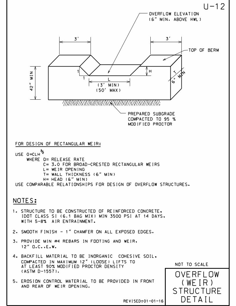
T
TOP OF BERM
H
L
42
" M
IN
NOTES:
OVERFLOW
(WEIR)
STRUCTURE
DETAIL
NOT TO SCALE
3/2
FOR DESIGN OF RECTANGULAR WEIR:
USE Q=CLH
WHERE Q= RELEASE RATE
C= 3.0 FOR BROAD-CRESTED RECTANGULAR WEIRS
L= WEIR OPENING
T= WALL THICKNESS (6" MIN)
H= HEAD (6" MIN)
USE COMPARABLE RELATIONSHIPS FOR DESIGN OF OVERFLOW STRUCTURES.
6" M
IN
OVERFLOW ELEVATION
(6" MIN. ABOVE HWL)
1
1
PREPARED SUBGRADE
COMPACTED TO 95 %
MODIFIED PROCTOR
U-12
1. STRUCTURE TO BE CONSTRUCTED OF REINFORCED CONCRETE,
IDOT CLASS SI (6.1 BAG MIX) MIN 3500 PSI AT 14 DAYS,
WITH 5-8% AIR ENTRAINMENT.
2. SMOOTH FINISH - 1" CHAMFER ON ALL EXPOSED EDGES.
3. PROVIDE MIN #4 REBARS IN FOOTING AND WEIR,
12" O.C.,E.W.
4. BACKFILL MATERIAL TO BE INORGANIC COHESIVE SOIL,
COMPACTED IN MAXIMUM 12" (LOOSE) LIFTS TO
AT LEAST 90% MODIFIED PROCTOR DENSITY
(ASTM D-1557).
5. EROSION CONTROL MATERIAL TO BE PROVIDED IN FRONT
AND REAR OF WEIR OPENING.
REVISED:01-01-16
(3’ MIN)
(50’ MAX)
3’ 3’

NOTE:
NOT TO SCALE
"OPTIONAL"
6" TO 4" REDUCER
PROVIDE FITTINGS
AS NECESSARY
2" SUMP PUMP DISCHARGE
FACE OF BUILDING
3’
MIN
HEIGHT VARIES,
BUT 6" MIN
2" (MIN)
AIR GAP
SUMP PUMP DISCHARGE
CONNECTION DETAIL
SLEEVE AND
CAULK OPENING
4" P.V.C. DRAIN
(CONNECT TO PUBLIC
STORM SEWER SYSTEM)
1. SUMP PUMPS SHALL BE DESIGNED WITH A MINIMUM 2" AIR GAP. A RIGID
FOUR-INCH (4") DIAMETER PVC PIPE CAN BE USED TO CONNECT THE
INDIVIDUAL SUMP PUMP SERVICE TO THE STORM SEWER. IN NO EVENT
SHALL THE SUMP PUMP DISCHARGE INTO THE SANITARY SEWER SYSTEM.
2. A PLUMBING PERMIT IS REQUIRED PRIOR TO ANY SEWER CONNECTION.
U-13
REVISED:01-01-16

15’-0"
1
3
1
2
3
4
- WRAP WITH POROUS LANDSCAPING CLOTH
- 12" DEEP GRAVEL BED UNDER PERFORATED PIPE
- POP-UP DRAINAGE EMITTER OR GRATE
6"DIA. PVC PIPE (SDR 26)
2
4
6"
0.5% MIN. 0.5% MIN.
- PERFORATED PVC PIPE (HOLES AT THE BOTTOM OF PIPE)
NOT TO SCALE
YARD DRAIN WITH GRATE (AT LOWEST POINT)
PVC 90 ELBOW
w/ 14" DRAIN HOLE
2’-0"
MIN
.
PROPOSED OR EXISTING
BUILDING
STORM SEWER
PIPING IN
"UNSEWERED AREAS"
DETAIL
2" (MIN.)
AIR GAP
U-14
BACK
PROPERTY
LINE
FINISHED
GRADE
SUMP PUMP
CONNECTION
DISCLAIMER:
THIS DRAWING WAS GENERATED BY THE VILLAGE FOR INFORMATION
PURPOSES ONLY.SINCE THE PROPOSED STORM SEWER PIPE IS LOCATED
ON PRIVATE PROPERTY IT IS A PRIVATE SYSTEM. CONSEQUENTLY IT
IS HOMEOWNERS RESPONSIBILITY TO MAINTAIN THIS STORM SEWER
PIPING SYSTEM
HEIGHT
VARIES,
MIN. 6"
4"DIA. PVC
PIPE(SDR 26)
FRONT/SIDE
PROPERTY
LINE
10’ MIN.
(OR AS APPROVED BY
VILLAGE ENGINEER*)
* DUE TO POTENTIAL ICING ISSUES ON ROADS AND/OR SIDEWALK,
THE DISCHARGE POINT MAY BE BACK MORE THAN 10’
REVISED:01-01-16

VALVE VAULT SHALL BE
CONSTRUCTED WITH
PRECAST REINFORCED
CONCRETE SECTIONS
VALVE VAULT
WATERMAIN
VALVE
SECTION A-A
}
16"O
.C.
11
"
7"
NOT TO SCALE
A A
TWO (2) BUTYL RUBBER
STRIPS (TYPICAL)
(O
R M
EE
T E
XIS
T. C
ON
DIT
IO
NS
)
CONCRETE SUPPORT
WATERMAIN
VALVE
.
2’-0"
6’-0
" M
IN
IM
UM
12
"
MIN
.
NOTES:
SEE
NOTE 1.
VALVE
VAULT
DETAIL
6" 6"
RUBBER BOOT (TYP.)
6" REINFORCED
CONCRETE SLAB
CAST INTEGRAL
WITH LOWEST
BARREL SECTION
4" MIN.SAND CUSHION
"MEGALUG" RESTRAINT
W/"COR-TEN BOLTS"
STEEL REINFORCED
POLYURETHANE STEPS (12" WIDE)
15"(MIN) 39"(MIN)
U-15
NEENAH R-1713 FRAME & LID,
WITH "WATER" CAST INTO COVER
TWO (2) MAX. HDPE PLASTIC
ADJUSTING RINGS
(8" MAX.), SEE DETAIL U-1
1. 60" (MIN) INSIDE DIA. FOR ALL VALVE VAULTS.
2. VALVE VAULT MUST CONFORM TO ASTM C-478.
3. USE ECCENTRIC CONE ONLY.
4. VAULT SECTIONS TO BE TONGUE AND GROOVED.
5. NON-PRECAST OPENINGS SHALL BE CORED, RUBBER BOOTED, AND MORTORED.*
6. BACKFILL MATERIAL SHALL BE IDOT CA 7 STONE.
7. a) MECHANICAL JOINT BOLTS & NUTS SHALL BE COMPOSED OF CORE-TEN.
b) ALL OTHER HEXAGONAL BOLTS & NUTS SHALL BE COMPOSED OF STAINLESS STEEL.
8. TRACER WIRE SHALL BE USED ON ALL PIPE INSTALLATIONS, REGARDLESS OF PIPE
MATERIAL.
* SEE PIPE CONNECTION TO STRUCTURE DETAIL U-5. REVISED:01-01-16
ATTACH TRACER WIRE
IN A THREADED
"EYE" BOLT AT TOP
OF VALVE VAULT

VALVE VAULT SHALL BE
CONSTRUCTED WITH
PRECAST REINFORCED
CONCRETE SECTIONS
VALVE VAULT
SECTION A-A
}
16"O
.C.
11
"
7"
NOT TO SCALE
A A
TWO (2) BUTYL RUBBER
STRIPS (TYPICAL)
(O
R M
EE
T E
XIS
T. C
ON
DIT
IO
NS
)
CONCRETE SUPPORT
2’-0"
6’-0
" M
IN
IM
UM
12
"
MIN
.
NOTES:
6" 6"
6" REINFORCED
CONCRETE SLAB
CAST INTEGRAL
WITH LOWEST
BARREL SECTION
4" MIN.SAND CUSHION
BUTTERFLY
VALVE
6"MIN.
1’-0"
2’-0"
2’0"4’0"
3’0"4’0"
3’6"4’6" 36" WATER MAIN
24" WATER MAIN
BUTTERFLY
VALVE
VAULT
DETAIL
RUBBER BOOT (TYP)
STEEL REINFORCED (12" WIDE)
POLYURETHANE STEPS
16"-20" WATER MAIN
U-16
NEENAH R-1713 FRAME & LID,
WITH "WATER" CAST INTO COVER
WATER MAIN
16", 20", 24", OR 36"
WATER MAIN
1. VALVE VAULT MUST CONFORM TO ASTM C-478.
2. USE ECCENTRIC CONE ONLY.
3. VAULT SECTIONS TO BE TONGUE AND GROOVED.
4. NON-PRECAST OPENING TO BE CORED, RUBBER BOOTED, AND MORTARED.*
5. BACKFILL MATERIAL SHALL BE IDOT CA 7 CRUSHED STONE.
6. ALL BOLTS SHALL BE STAINLESS STEEL.
7. TRACER WIRE SHALL BE USED ON ALL PIPE INSTALLATIONS, REGARDLESS
OF PIPE MATERIAL.
* SEE PIPE CONNNECTIONS TO STRUCTURE DETAIL U-5.
TWO (2) MAX. HDPE PLASTIC
ADJUSTING RINGS MORTARED
(8" MAX.), SEE DETAIL U-1
REVISED:01-01-16

METER VAULT SHALL BE
CONSTRUCTED WITH
PRECAST REINFORCED
CONCRETE SECTIONS
}
16"O
.C.
11"
7"
NOT TO SCALE
TWO (2) BUTYL RUBBER
STRIPS (TYPICAL)
(O
R M
EE
T E
XIS
T.
CO
ND
IT
IO
NS
)
CONCRETE SUPPORT
2’-0"6
’-0
" M
IN
IM
UM
12"
MIN
.
NOTES:
6" 6"
RUBBER BOOT (TYP.)6" REINFORCED
CONCRETE SLAB
CAST INTEGRAL
WITH LOWEST
BARREL SECTION
48"(MIN)
4" MIN.SAND CUSHION
PIT-SET
METER
VAULT
DETAIL
Z
B-BOX
ROUNDWAY
METER
BALL VALVE
STEEL REINFORCED
POLYURETHANE STEPS (12" WIDE)
NEENAH R-1713, FRAME & LID
WITH "WATER" CAST INTO COVER
1. 48" (MIN) INSIDE DIA. FOR ALL VALVE VAULTS.
2. VALVE VAULT MUST CONFORM TO ASTM C-478.
3. USE ECCENTRIC CONE ONLY.
4. VAULT SECTIONS TO BE TONGUE AND GROOVED.
5. NON-PRECAST OPENINGS TO BE CORED AND RUBBER BOOTED.*
6. BACKFILL MATERIAL SHALL BE IDOT CA-7 STONE.
* SEE PIPE CONNECTION TO STRUCTURE DETAIL U-5.
U-17
TWO (2) MAX. HDPE PLASTIC
ADJUSTING RINGS MORTARED
(8" MAX.), SEE DETAIL U-1
REVISED:01-01-16
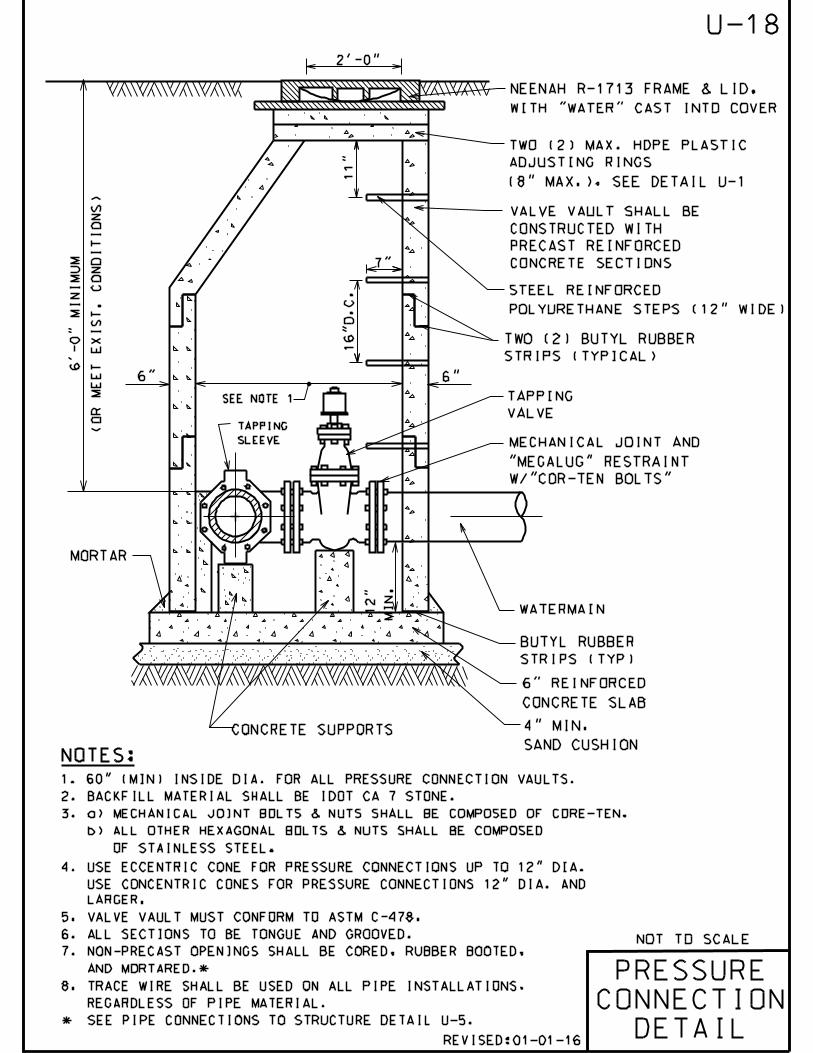
16"O
.C.
11"
7"
NOT TO SCALE
WATERMAIN
MORTAR
.
2’-0"
12"
MIN
.
NOTES:
PRESSURE
CONNECTION
DETAIL
(O
R M
EE
T E
XIS
T.
CO
ND
IT
IO
NS
)
6’-0" M
IN
IM
UM
VALVE VAULT SHALL BE
CONSTRUCTED WITH
PRECAST REINFORCED
CONCRETE SECTIONS
TWO (2) BUTYL RUBBER
STRIPS (TYPICAL)
4" MIN.
SAND CUSHION
6" REINFORCED
CONCRETE SLAB
TAPPING
SLEEVE
SEE NOTE 1 TAPPING
VALVE
CONCRETE SUPPORTS
6" 6"
BUTYL RUBBER
STRIPS (TYP)
MECHANICAL JOINT AND
"MEGALUG" RESTRAINT
W/"COR-TEN BOLTS"
STEEL REINFORCED
POLYURETHANE STEPS (12" WIDE)
U-18
NEENAH R-1713 FRAME & LID,
WITH "WATER" CAST INTO COVER
TWO (2) MAX. HDPE PLASTIC
ADJUSTING RINGS
(8" MAX.), SEE DETAIL U-1
REVISED:01-01-16
1. 60" (MIN) INSIDE DIA. FOR ALL PRESSURE CONNECTION VAULTS.
2. BACKFILL MATERIAL SHALL BE IDOT CA 7 STONE.
3. a) MECHANICAL JOINT BOLTS & NUTS SHALL BE COMPOSED OF CORE-TEN.
b) ALL OTHER HEXAGONAL BOLTS & NUTS SHALL BE COMPOSED
OF STAINLESS STEEL.
4. USE ECCENTRIC CONE FOR PRESSURE CONNECTIONS UP TO 12" DIA.
USE CONCENTRIC CONES FOR PRESSURE CONNECTIONS 12" DIA. AND
LARGER.
5. VALVE VAULT MUST CONFORM TO ASTM C-478.
6. ALL SECTIONS TO BE TONGUE AND GROOVED.
7. NON-PRECAST OPENINGS SHALL BE CORED, RUBBER BOOTED,
AND MORTARED.*
8. TRACE WIRE SHALL BE USED ON ALL PIPE INSTALLATIONS,
REGARDLESS OF PIPE MATERIAL.
* SEE PIPE CONNECTIONS TO STRUCTURE DETAIL U-5.

NOT TO SCALE
NOTE:
THRUST BLOCK
DETAIL
U-19
1. ALL BENDS OF 10 AND LARGER SHALL BE BLOCKED WITH AT LEAST 10" THICK
POURED IN PLACE CONCRETE BLOCKS AGAINST UNDISTURBED VERTICAL EARTH FACE.
2. ALL CONCRETE TO BE MIN. 3,000 PSI.
3. IN ADDITION TO THE ABOVE THRUST BLOCKING:
ALL MECHANICAL JOINTS, (BENDS OVER 10, TEES,
CROSSES, VALVES AND FIRE HYDRANTS) SHALL HAVE
A "MEGALUG" RESTRAINT, OR AS APPROVED BY
VILLAGE ENGINEERING. BOLTS SHALL BE "COR-TEN".
REVISED:01-01-16
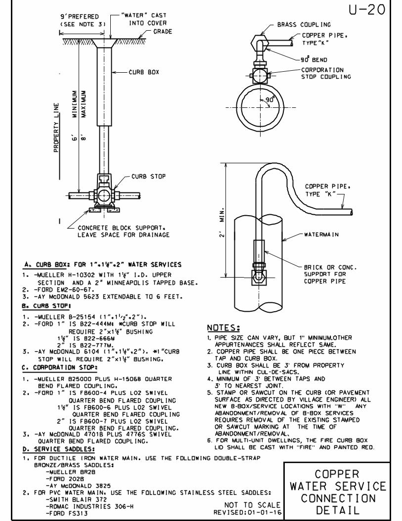
PR
OP
ER
TY
LIN
E
GRADE
CURB BOX
CURB STOP
CONCRETE BLOCK SUPPORT,
LEAVE SPACE FOR DRAINAGE
0
BRASS COUPLING
COPPER PIPE,
TYPE"K"
90 BEND
90
0
COPPER PIPE,
TYPE "K"
WATERMAIN 2’
MIN
.
6’ M
IN
IM
UM
NOT TO SCALE
CORPORATION
STOP COUPLING
8’
M
AX
IM
UM
"WATER" CAST
INTO COVER
9’PREFERED
(SEE NOTE 3)
BRICK OR CONC.
SUPPORT FOR
COPPER PIPE
B. CURB STOP:
1. -MUELLER B-25154 (1",1%%129",2").
C. CORPORATION STOP:
1. -MUELLER H-10302 WITH 1 12" I.D. UPPER
SECTION AND A 2" MINNEAPOLIS TAPPED BASE.
2. -FORD EM2-60-67.
3. -AY McDONALD 5623 EXTENDABLE TO 6 FEET.
A. CURB BOX: FOR 1",1 12",2" WATER SERVICES
2. -FORD 1" IS B22-444M; *CURB STOP WILL
REQUIRE 2"x1 12" BUSHING
1 12" IS B22-666M
2" IS B22-777M.
1. -MUELLER B25000 PLUS H-15068 QUARTER
BEND FLARED COUPLING.
2. -FORD 1" IS FB600-4 PLUS L02 SWIVEL
QUARTER BEND FLARED COUPLING
1 12" IS FB600-6 PLUS L02 SWIVEL
QUARTER BEND FLARED COUPLING
2" IS FB600-7 PLUS L02 SWIVEL
QUARTER BEND FLARED COUPLING.
3. -AY McDONALD 4701B PLUS 4776S SWIVEL
QUARTER BEND FLARED COUPLING.
COPPER
WATER SERVICE
CONNECTION
DETAIL
U-20
3. -AY McDONALD 6104 (1",1 12",2"). *1"CURB
STOP WILL REQUIRE 2"x1 12" BUSHING.
REVISED:01-01-16
1. FOR DUCTILE IRON WATER MAIN, USE THE FOLLOWING DOUBLE-STRAP
BRONZE/BRASS SADDLES:
-MUELLER BR2B
-FORD 202B
-AY McDONALD 3825
2. FOR PVC WATER MAIN, USE THE FOLLOWING STAINLESS STEEL SADDLES:
-SMITH BLAIR 372
-ROMAC INDUSTRIES 306-H
-FORD FS313
D. SERVICE SADDLES:
1. PIPE SIZE CAN VARY, BUT 1" MINIMUM.OTHER
APPURTENANCES SHALL REFLECT SAME.
2. COPPER PIPE SHALL BE ONE PIECE BETWEEN
TAP AND CURB BOX.
3. CURB BOX SHALL BE 3’ FROM PROPERTY
LINE WITHIN CUL-DE-SACS.
4. MINIMUM OF 3’ BETWEEN TAPS AND
3’ TO NEAREST JOINT.
5. STAMP OR SAWCUT ON THE CURB (OR PAVEMENT
SURFACE AS DIRECTED BY VILLAGE ENGINEER) ALL
NEW B-BOX/SERVICE LOCATIONS WITH "W". ANY
ABANDONMENT/REMOVAL OF B-BOX SERVICES
REQUIRES REMOVAL OF THE EXISTING STAMPED
OR SAWCUT MARKING AT THE TIME OF
ABANDONMENT/REMOVAL.
6. FOR MULTI-UNIT DWELLINGS, THE FIRE CURB BOX
LID SHALL BE CAST WITH "FIRE" AND PAINTED RED.
NOTES:

EXISTING OR PROPOSED GRADE
10’ 10’
MIN. MIN.
18"
MIN
.
45^
PROPOSED DIP
WATERMAIN
"MEGALUG"
RESTRAINT W/
"COR-TEN"
BOLTS (TYP.)
NOTES:
NOT TO SCALE
WATER MAIN
CROSSING
DETAIL
MIN.6"
GRAVITY SEWER TO BE WATER
MAIN QUALITY PRESSURE PIPE
FOR A MINIMUM DISTANCE OF 10’
ON EITHER SIDE OF THE OUTSIDE
WALL OF THE WATER MAIN.
SEE NOTES 3,4 AND 5 BELOW.
6’-0
" M
IN
.
4" (MIN.)
1. HORIZONTAL AND VERTICAL SEPARATION BETWEEN WATERMAINS AND SEWERS SHALL
COMPLY WITH VILLAGE OF GLENVIEW ENGINEERING STANDARDS MANUAL OR IEPA
REQUIREMENTS, WHICHEVER IS MORE STRINGENT.
2. CONTRACTOR MAY BEND WATER MAIN PIPE UNIFORMLY UNDER SEWERS WITHOUT USING
FITTINGS, PROVIDED THAT JOINT DEFLECTION DOES NOT EXCEED 5 DEGREES PER
JOINT FOR PIPE UNDER 14" IN DIAMETER AND 3 DEGREES PER JOINT FOR PIPE 14"
AND OVER IN DIAMETER. IF FITTINGS ARE USED, CONTINUOUS STRAPPING WITH
RODS, STRAPS, NUTS AND BOLTS BELOW NORMAL WATERMAIN DEPTH ARE
REQUIRED, OR RETAINER GLANDS MAY BE USED IN LIEU OF STRAPPING. RETAINER
GLANDS TO BE "MEGALUG" RESTRAINT, SERIES 1100 OR APPROVED EQUAL WITH
"COR TEN" BOLTS.
3. ALL SANITARY SEWER (INCLUDING SERVICE) CROSSINGS WHERE THE WATER MAINS
OR WATER SERVICES ARE LESS THAN 18" VERTICALLY ABOVE THE SEWER SHALL BE
POLYVINYL CHLORIDE PRESSURE PIPE (SDR 26-160 PSI) AND SHALL CONFORM WITH
THE LATEST REVISION OF ASTM D- 2241. JOINTS SHALL CONFORM TO ASTM
D-3139 AND ELASTOMERIC GASKETS SHALL CONFORM TO ASTM F-477. THE SAME
PIPE AND JOINT MATERIALS SHALL BE USED WHENEVER WATER MAIN CROSSES
BELOW THE SEWER.
4. ALL STORM SEWER (INCLUDING SERVICE) CROSSINGS WHERE THE WATER MAINS
ARE LESS THAN 18" VERTICALLY ABOVE THE SEWER SHALL BE REINFORCED
CONCRETE PIPE, ASTM C-361, CLASS D-25,WITH BELL AND SPIGOT JOINTS AND
RUBBER GASKETS, OR PVC SDR 26 AS SPECIFIED IN NOTE 3 ABOVE. THE SAME
PIPE AND JOINT MATERIAL SHALL BE USED WHENEVER WATER MAIN CROSSES
BELOW THE SEWER.
5. FOR NEW SEWER INSTALLATIONS CROSSING OVER WATER MAINS,
THE ENTIRE RUN OF NEW SEWER SHALL BE WATER MAIN QUALITY
PIPE, EXTENDING FROM STRUCTURE TO STRUCTURE ON EACH
SIDE OF THE CROSSING.
U-21
IDOT CA 7 COMPACTED TO 95% MODIFIED
PROCTOR DENSITY (ASTM D-1557)
TRENCH BACKFILL SHALL BE USED FOR
SEWER PIPE OVER WATER MAIN PIPE SUPPORT
REVISED:01-01-16

(T.B.)
2’-0"
NOT TO SCALE
GEOTEXTILE
FABRIC OVER
AGGREGATE
BACKFILL
8"MIN
20
" M
IN
2’-0" (
MIN
)
HYDRANT
DETAIL
2"MIN
4"MAX
COUPLING
BOLTLESS
CONNECTION
DRAIN
HOLES
MUST BE
KEPT
CLEAR
2’-0"
(M
IN
)
90 SPREAD BETWEEN
PORT NOZZLES
(PUMPERS)
0
AUXILIARY BOX
666S
"MEGALUG" RESTRAINT
OR APPROVED EQUAL.
BOLTS SHALL BE
"COR-TEN"
U-22
SAND (FA6
BACKFILL)
6"(DIA)X18"(LONG)
FOR PUBLICLY
OWNED HYDRANTS
USE RUSTOLEUM OIL
BASED ENAMEL
SAFETY YELLOW
#7644.
FOR PRIVATELY
OWNED HYDRANTS
USE SAFETY
RED #7664
REVISED:01-01-16
FINAL GRADE
NOTES:
SEE THRUST
BLOCK DETAIL U-19
HYDRANT
LEAD
LENGTH
MIN
. 5’-6" B
UR
Y
6’-0
" C
OV
ER
FO
R W
AT
ER
MA
IN
LIN
E
SEE DETAIL U-35
FOR AUXILIARY
VALVE AND BOX
BACKFILL TO
CONSIST OF
IDOT CA 7.
WATER
MAIN
1. U.S.PIPE, M-94 HYDRANT OR CLOW F-2545 HYDRANT.
2. ALL HYDRANTS TO HAVE DOUBLE STEAMERS-2 4 12" P.N.,N.S.T.,
3. MECHANICAL JOINT SHOE WITH 6" RESILIENT WEDGE AUXILIARY VALVE.
4. MAIN VALVE OPENING SHALL BE 5 14".
5. HYDRANT BARREL SHALL BE ONE PIECE DUCTILE IRON PIPE,
POLY-WRAPPED (AS WATER MAIN) TO HYDRANT BASE.
6. HYDRANT LEADS TO BE 6" DIAMETER UP TO 25’ LONG
AND 8" DIAMETER IF GREATER THAN 25’.
CONCRETE
BLOCK
SUPPORTS
EXTENSION
COUPLING
HYDRANT
EXTENSION
(IF REQUIRED)

EXISTING OR
REPLACED SEWER EXISTING SEWER
PIPE
COUPLING
DETAIL
NOT TO SCALE
BUTT PIPES OF MATCHING
DIAMETERS TOGETHER
NON-SHEAR BAND SEAL
COUPLING OR EQUAL
U-23
REVISED:01-01-16

MIN.12" PLUS O.D. OF PIPE
12"
6" MIN.
NOT TO SCALE
.
.
NOTES:
.
BACKFILL TO 12"
ABOVE TOP OF PIPE
SHALL CONSIST
OF AGGREGATE CA 7
UNDERCUT UNSUITABLE
AREAS WHERE DIRECTED AND
REPLACE WITH AGGREGATE CA 7
4" MIN.
AGGREGATE CA 7
BEDDING
(SEE NOTE #3)
UTILITY PIPE
.
12" LIFT
12" LIFT
O.D
.
UTILITY TRENCH
IN NON-PAVED
AREAS DETAIL
4" MIN. TOPSOIL & SOD (OR SEED
IF APPROVED BY VILLAGE ENGINEERING)
GEOTEXTILE FABRIC
U-24
AGGREGATE CA 7
(CRUSHED)
PLACE BACKFILL
MATERIAL IN 12" LIFTS
(MAX) AND COMPACT
EACH LIFT TO 90% OF
MODIFIED PROCTOR
DENSITY (ASTM D-1557)
.
AGGREGATE FA 6
(SEE NOTE #4)MAX 18" PLUS PIPE O.D. FOR TRENCHES <5’ DEEP
MAX 36" PLUS PIPE O.D. FOR TRENCHES >5’ DEEP
8"8" OF SELECT
BACKFILL MATERIAL
1. ALL BACKFILL MATERIALS SHALL BE PROPERLY COMPACTED.
2. ALL TRENCH EXCAVATIONS SHALL MEET OSHA REQUIREMENTS.
3. BEDDING MATERIAL FOR PVC PIPE INSTALLATION
SHALL COMPLY WITH ASTM D-2321.
4. FOR WATER MAIN TRENCHES, CA 7 SHALL EXTEND UP
TO TWELVE (12) INCHES FROM FINISHED GRADE.
WATER SERVICE TRENCHES SHALL BE BACKFILLED
PER THIS DETAIL.
REVISED:01-01-16
6" MIN.

6" MIN.
12"
6" MIN.
NOT TO SCALE
.
.
.
BACKFILL TO 12"
ABOVE TOP OF PIPE
SHALL CONSIST
OF AGGREGATE CA 7
4" MIN.
AGGREGATE CA 7
BEDDING
(SEE NOTE #4)
.
.UTILITY PIPE
O.D
.
UNDERCUT UNSUITABLE
AREAS WHERE DIRECTED AND
REPLACE WITH AGGREGATE
CA 7
.
UTILITY TRENCH
IN PAVEMENT
AREAS DETAIL
SEE NOTE #1
GEOTEXTILE
FABRIC
NOTES:
U-25
CA 7 CRUSHED
AGGREGATE
12"CA6 CAP
SEE PAVEMENT PATCH
DETAIL P-4
MAX 18" PLUS PIPE O.D. FOR TRENCHES <5’ DEEP
MAX 36" PLUS PIPE O.D. FOR TRENCHES >5’ DEEP
1. TRENCH BACKFILL UNDER A PAVED SURFACE OR WITHIN THE ZONE
OF INFLUENCE (5’ FROM EDGE OF PAVEMENT OR 5’ FROM THE BACK OF
CURB ON CURBED STREETS) SHALL CONSIST OF:
a) UNDER NEW PAVEMENT:
12" THICK PAVEMENT SUBGRADE (AGGREGATE CA 6 CAP) OVER
AGGREGATE CA 7 TRENCH BACKFILL OR CONTROLLED LOW STRENGTH
MATERIAL (CLSM) MIX 1 (ONLY IF REQUIRED BY VILLAGE ENGINEERING)
b) UNDER EXISTING PAVEMENT:
SAME AS ’a’ ABOVE
c) UNDER PRIVATELY OWNED PAVEMENT:
SAME AS ’a’ ABOVE.
2. ALL MATERIALS SHALL BE PROPERLY COMPACTED PER SPECIFICATIONS
(INUNDATION OR WATER JETTING IS NOT ALLOWED).
3. ALL TRENCH EXCAVATIONS SHALL MEET OSHA REQUIREMENTS.
4. BEDDING MATERIAL FOR PVC PIPE INSTALLATION SHALL COMPLY WITH
ASTM D-2321.
5. IF APPROVED BY VILLAGE ENGINEERING, A ONE (1) INCH THICK STEEL
PLATE SHALL BE PROVIDED AND MAINTAINED BY CONTRACTOR UNTIL
THE SURFACE RESTORATION IS COMPLETE. THE PLATE SHALL BE
PROTECTED FROM SLIDING AND PROVIDED WITH BITUMINOUS RAMPS
IF REQUIRED BY VILLAGE ENGINEERING.
6. PRIOR TO PLACEMENT OF PAVEMENT MATERIALS, THE EXISTING
EXPOSED EDGES SHALL BE SAWCUT TO PROVIDE A SMOOTH CLEAN
EDGE, FREE OF LOOSE MATERIAL.
7. THE PLACEMENT OF PAVEMENTS SHALL NOT BE ALLOWED WITHOUT
PRIOR APPROVAL BY VILLAGE ENGINEERING.
REVISED:01-01-16

6"
TEE OR WYE CONNECTION
NOT TO SCALE
NOTES:
CONCRETE ENCASEMENT
FOR
CA 7
SUBGRADE
U-26
SEE NOTE 6
PROPOSED SANITARY
OR STORM SEWER SERVICE
EXISTING SANITARY
OR STORM SEWER MAINS
NEW SEWER
SERVICE
DETAIL REVISED:01-01-16
TRENCH WALL
1. FOR PROPOSED STORM SEWER SERVICES LESS THAN 8" DIA., CORE THE
PIPE AND USE A BOOT CONNECTION.
2. FOR PROPOSED STORM SEWER SERVICES OVER 10" DIA., A MANHOLE MUST
BE INSTALLED.
3. FOR PROPOSED STORM OR SANITARY SEWER SERVICES, ENCASE ALL
CONNECTIONS IN LOW STRENGTH CONCRETE TO PREVENT THE FITTINGS
FROM ROTATING.
4. FOR TRENCHES WITHIN AN EXISTING PAVED SURFACE AREA OR WITHIN
THE ZONE OF INFLUENCE, USE CA 7 CRUSHED AGGREGATE OR
CONTROLLED LOW STRENGTH MATERIAL (CLSM) MIX 1 (ONLY IF REQUIRED
BY VILLAGE ENGINEERING). USE EXCAVATED MATERIAL IN ALL OTHER
AREAS.
5. ALL TRENCH EXCAVATIONS SHALL MEET OSHA REQUIREMENTS.
6. STAMP OR SAWCUT ON THE CURB (OR PAVEMENT SURFACE AS DIRECTED
BY VILLAGE ENGINEERING) ALL NEW SERVICE LOCATIONS WITH "S"
(SANITARY) OR "ST" (STORM) RESPECTIVELY.

NOT TO SCALE
NOTE:PIPE
UNDERDRAIN
DETAIL
18
" M
INIM
UM
SECTION A-A
18" MINIMUM
7"7" 4"
PIPE UNDERDRAIN
4" PERFORATED
RIGID PVC (SDR 26)
SHALL BE PITCHED
TO STORM STRUCTURE
PIPE OPENINGS
PLACED ON BOTTOM
OF PIPE
GEOTEXTILE FABRIC
TO OVERLAP TOP
4" MIN (TYP)
PERMEABLE
FABRIC (SOCK)
IDOT CA 7
(CRUSHED)
SUB-GRADE
(CA 6)
STORM
SEWER
LATERAL
PAVEMENT SUBGRADE
DOWNSTREAM
INLET OR MANHOLE
(TYPICAL)
A
PCC CURB
A
10’ TYP.
MINIMUM
SLOPE = 1%
PIPE UNDERDRAIN PLAN VIEW
UNDERDRAIN TO BE INSTALLED IF INDICATED ON PLANS
AND/OR REQUESTED BY VILLAGE ENGINEERING.
4" PIPE (NOT OPTIONAL)
UNDERDRAIN TO EXTEND
LONGITUDINALLY ALONG
PAVEMENT, WITH EACH
UPSTREAM END PLUGGED.
CONNECT TO THE DOWN-
STREAM INLET OR MANHOLE.
OPTIONAL:
LATERAL COULD BE PERFORATED
PVC WITH GEOTEXTILE FABRIC
AS DETAILED BELOW
U-27
REVISED:01-01-16

CL
SURFACE GRADE
(TYP)
NOT TO SCALE
10’
MIN.
10’
MIN.
NOTES:
CASING PIPE
DETAIL
MIN 38" THICK BITUMINOUS COATED
STEEL CASING PIPE, AUGERED & JACKED
EXISTING
PAVEMENT
8"
MIN.
EXISTING BACK
OF CURB
INSTALL ALL STAINLESS STEEL CASING
SPACERS (BY CASCADE OR APPROVED EQUAL)
FOR EACH PIPE LENGTH ON 6’ CENTERS, OF
THE SIZE RECOMMENDED BY THE MANUFACTURER
SANITARY SEWER,
STORM SEWER OR
WATER MAIN
(CARRIER PIPE)
BRICK AND MORTAR BULKHEAD
(BOTH ENDS) AS APPROVED BY
VILLAGE ENGINEERING, PRIOR
TO BACKFILLING.
1. CASING PIPE IS REQUIRED UNDER ALL EXISTING ROADWAYS, OR
AS OTHERWISE DIRECTED BY VILLAGE ENGINEERING WHERE OPEN
CUTS ARE NOT PERMITTED, EXCEPT FOR WATER SERVICE
LINES UP TO 2" IN DIAMETER.
2. WATER MAIN CASING SPACERS SHALL BE RESTRAINED IN POSITION.
3. THE INSIDE DIAMETER OF THE CASING PIPE SHALL BE DETERMINED
BY CONTRACTOR BUT IN NO CASE SHALL IT BE LESS THAN 8" LARGER
THAN THE DIAMETER OF THE CARRIER PIPE TO ALLOW AMPLE SPACE
FOR BELLS, AND CARRIER PIPE SLOPE (FOR GRAVITY PIPE).
4. ALL AUGER PITS TO BE BACKFILLED WITH IDOT CA 7 (CRUSHED)
AGGREGATE MATERIAL.
U-28
REVISED:01-01-16

NOT TO SCALE
NON- SHRINK MORTAR
UNDISTURBED GROUND
%%
p12"
%%
p6"
12"
U-29
SECTION A-A
%%
p12"
A
2" MAX.
PLAN
NOTES:
%%
p12"
A
CONCRETE ANCHOR
(ALL AROUND)
3500 PSI CONC.
TRIM PROPOSED
STORM SEWER PIPE
PROTRUSION TO
CONTOURS OF MAIN
STORM SEWER PIPE
INCOMING PROPOSED
STORM SEWER LATERAL
(10" DIA. MAXIMUM -
SEE NOTE 3)
EXISTING STORM SEWER
(18" DIA. & LARGER)
PROPOSED
REINFORCED
CONCRETE
OR PVC PIPE
(10" DIA. MAXIMUM -
SEE NOTE 3)
1. FOR EXISTING STORM SEWER PIPES SMALLER
THAN 18" DIA. A NEW FITTING (WYE, TEE)
INSERT SHALL BE PROVIDED.
2. FOR CONNECTION OF PVC SEWER LATERALS
TO EXISTING PVC STORM SEWER A NEW FITTING
(WYE, TEE) INSERT SHALL BE PROVIDED UNLESS
APPROVED OTHERWISE BY VILLAGE ENGINEERING.
3. FOR STORM SEWER LATERALS OVER 10" DIA.,
CONSTRUCTION OF NEW STORM SEWER MANHOLE
AT CONNECTION POINT SHALL BE REQUIRED UNLESS
APPROVED OTHERWISE BY VILLAGE ENGINEERING.
EXISTING STORM SEWER
(18" DIA. & LARGER)
THE CONTRACTOR SHALL CORE
THE EXISTING PIPE UNLESS
DIRECTED DIFFERENTLY BY
VILLAGE ENGINEERING
STORM SEWER
CONNECTION
TO EXISTING
PIPE DETAIL REVISED:01-01-16

NOT TO SCALE
NOTES:
U-30
SEWER SERVICE
REPLACEMENT
DETAIL
MIN.
6"
* PIPE MATERIAL:PVC SDR 26, ASTM D2241
PROPOSED
CLEANOUT
(TYPICAL)
PLAN VIEW
CURB & GUTTER
EX
RO
W
EX
RO
WE
X R
OW
EX
RO
W
5.0’(MIN)
5.0’ (MIN)
4"(MIN)
BEDDING
SECTION
PROPOSED WATER MAIN
(OR OTHER UTILITY)
NEW TEE
OR WYE
EXISTING
SEWER
SERVICE
TO REMAIN
EXISTING SEWER
SERVICE (PRIVATE)
PIPE TO REMAIN,
DIAMETER &
ELEVATION TO BE
FIELD VERIFIED BY
THE CONTRACTOR
(TYPICAL)
SECTION OF SEWER MAIN
TO BE REPLACED
* *
* *
* * LOCATE CLEANOUT AS CLOSE TO THE
PROPERTY LINE AS POSSIBLE
EXISTING SEWER MAIN WHICH MAY
BE REPAIRED & LINED
ROAD WIDTH VARIES
TRENCH
BACKFILL
(SEE NOTE 2)
NON-SHEAR BAND SEAL
SEE DETAIL U-23
EXISTING SEWER
SERVICE TO REMAIN
EXISTING SEWER
SERVICE TO BE
REMOVED
2’ (MIN) OFFSET
BETWEEN SERVICE
CONNECTIONS
CLEANOUTS WITHIN
DRIVEWAYS AND
SIDEWALKS SHALL
BE HOUSED WITHIN
CAST IRON BOX
6"x6" TEE &
6" RISER W/6"
INVERTED SCREW
CAP (TYPICAL)
CONNECT EX.
SEWER
SERVICE
PIPE
TRENCH WALL
SECTION OF SEWER MAIN
TO BE REPLACED
NEW TEE
OR WYE
PROPOSED 6" SEWER
SERVICE
@ 1.0% MIN
SEE DETAIL U-26
* PROP. 6" SEWER
SERVICE
@ 1.0% MIN
* PROPOSED
6" SEWER
SERVICE
@ 1.0% MIN
1. FOR REPLACED SEWER SERVICES, ENCASE ALL
CONNECTIONS IN LOW STRENGTH CONCRETE
TO PREVENT THE FITTINGS FROM ROTATING.
2. FOR TRENCHES WITHIN AN EXISTING PAVED SURFACE AREA
OR WITHIN THE ZONE OF INFLUENCE, USE CA 7 CRUSHED
AGGREGATE OR CONTROLLED LOW STRENGTH MATERIAL (CLSM).
MIX 1 (ONLY IF REQUIRED BY VILLAGE ENGINEERING). USE FA 6
AGGREGATE FOR TRENCH BACKFILL MATERIAL IN ALL OTHER AREAS.
3. STAMP OR SAWCUT ON THE CURB (OR PAVEMENT SURFACE AS
DIRECTED BY VILLAGE ENGINEERING) ALL NEW SERVICE LOCATIONS
WITH "S" (SANITARY) OR "ST" (STORM) RESPECTIVELY. ANY
ABANDONMENT/REMOVAL OF SERVICE REQUIRES REMOVAL OF THE
EXISTING STAMPED OR SAWCUT MARKING AT THE TIME OF
ABANDONMENT/REMOVAL.
EXISTING SEWER
SERVICE TO BE
REMOVED
REVISED:01-01-16
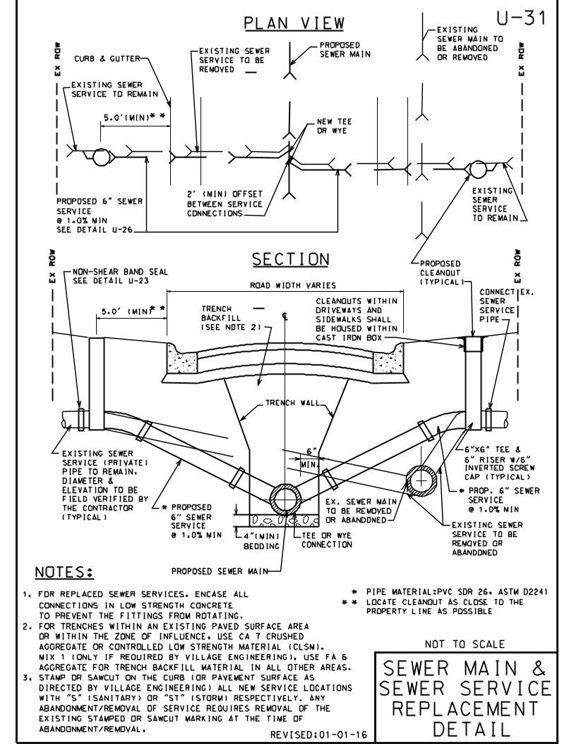
CL
PLAN VIEW
EX
RO
W
EX
RO
W
MIN.
6"
TEE OR WYE
CONNECTION
EX
RO
W
EX
RO
W
EXISTING SEWER
SERVICE TO BE
REMOVED OR
ABANDONED
EX. SEWER MAIN
TO BE REMOVED
OR ABANDONED
NOT TO SCALE
SEWER MAIN &
SEWER SERVICE
REPLACEMENT
DETAIL
* PIPE MATERIAL:PVC SDR 26, ASTM D2241
* * LOCATE CLEANOUT AS CLOSE TO THE
PROPERTY LINE AS POSSIBLE
U-31
EXISTING SEWER
SERVICE TO BE
REMOVED
CURB & GUTTER
EXISTING SEWER
SERVICE TO REMAIN
EXISTING
SEWER MAIN TO
BE ABANDONED
OR REMOVED
EXISTING
SEWER
SERVICE
TO REMAIN
NON-SHEAR BAND SEAL
SEE DETAIL U-23
5.0’ (MIN)
* *
5.0’(MIN)
* *
ROAD WIDTH VARIES
TRENCH
BACKFILL
(SEE NOTE 2)
TRENCH WALL
PROPOSED
CLEANOUT
(TYPICAL)
CONNECT EX.
SEWER
SERVICE
PIPE
CLEANOUTS WITHIN
DRIVEWAYS AND
SIDEWALKS SHALL
BE HOUSED WITHIN
CAST IRON BOX
6"X6" TEE &
6" RISER W/6"
INVERTED SCREW
CAP (TYPICAL)
EXISTING SEWER
SERVICE (PRIVATE)
PIPE TO REMAIN,
DIAMETER &
ELEVATION TO BE
FIELD VERIFIED BY
THE CONTRACTOR
(TYPICAL)
4"(MIN)
BEDDING
PROPOSED
SEWER MAIN
PROPOSED SEWER MAIN
PROPOSED 6" SEWER
SERVICE
@ 1.0% MIN
SEE DETAIL U-26
NEW TEE
OR WYE
2’ (MIN) OFFSET
BETWEEN SERVICE
CONNECTIONS
SECTION
* PROP. 6" SEWER
SERVICE
@ 1.0% MIN* PROPOSED
6" SEWER
SERVICE
@ 1.0% MIN
NOTES:
1. FOR REPLACED SEWER SERVICES, ENCASE ALL
CONNECTIONS IN LOW STRENGTH CONCRETE
TO PREVENT THE FITTINGS FROM ROTATING.
2. FOR TRENCHES WITHIN AN EXISTING PAVED SURFACE AREA
OR WITHIN THE ZONE OF INFLUENCE, USE CA 7 CRUSHED
AGGREGATE OR CONTROLLED LOW STRENGTH MATERIAL (CLSM).
MIX 1 (ONLY IF REQUIRED BY VILLAGE ENGINEERING). USE FA 6
AGGREGATE FOR TRENCH BACKFILL MATERIAL IN ALL OTHER AREAS.
3. STAMP OR SAWCUT ON THE CURB (OR PAVEMENT SURFACE AS
DIRECTED BY VILLAGE ENGINEERING) ALL NEW SERVICE LOCATIONS
WITH "S" (SANITARY) OR "ST" (STORM) RESPECTIVELY. ANY
ABANDONMENT/REMOVAL OF SERVICE REQUIRES REMOVAL OF THE
EXISTING STAMPED OR SAWCUT MARKING AT THE TIME OF
ABANDONMENT/REMOVAL. REVISED:01-01-16

CLCL
ROW ROW
RESTORE DISTURBED
PARKWAY WITH
4" TOPSOIL & SOD
%%p 6.0’
CURB &
GUTTER
%%p 6.5’ %%p 6.0’
PROPOSED 8"
WATER MAIN
CONNECTION TO
EXISTING
WATER SERVICE
18"
18"
PROPOSED 8"
SANITARY SEWER
(WATER QUALITY
PIPE)
REMOVE & REPLACE
EXISTING B-BOX
(SEE NOTE 2)
EXISTING WATER MAIN
TO BE REMOVED OR FILLED
CONNECTION TO
EXISTING
WATER SERVICE
REMOVE & REPLACE
EXISTING B-BOX
(SEE NOTE 2)
EXISTING PRIVATE
WATER SERVICE TO
REMAIN
EXISTING WATER SERVICE
TO BE ABANDONED
U-32
NOT TO SCALE
66.0’ ROW (TYP)
26.0’ B-B (TYP)
23.0’ E-E (TYP)
WATER SERVICE
REPLACEMENT
DETAIL #1
UNLESS
NOTED
OTHERWISE
PROPOSED 1 12"
WATER SERVICE
(COPPER PIPE)
PROPOSED
STORM SEWER
(WATER QUALITY
PIPE)
EXISTING
PRIVATE
WATER SERVICE
TO REMAIN
PROPOSED
ROAD
EXISTING SIDEWALK TO BE PROTECTED DURING
CONSTRUCTION. SIDEWALK SECTION REMOVAL
& REPLACEMENT SHALL BE APPROVED BY THE ENGINEER
NOTES:
1. SEE VOG STANDARD DETAIL U-20
FOR ADDITIONAL WATER SERVICE
CONNECTION INFORMATION.
2. EXISTING B-BOX TO BE LOCATED
BY THE VILLAGE OF GLENVIEW
PUBLIC WORKS DEPARTMENT.
REVISED:01-01-16

CLCL
U-33
NOT TO SCALE
WATER SERVICE
REPLACEMENT
DETAIL #2
RO
W
66.0’ ROW
26.0’ B-B
23.0’ E-E
ROW
PROPOSED ROAD
CURB &
GUTTER
CONNECTION TO
EXISTING
WATER SERVICE
18"
CONNECTION TO
EXISTING
WATER SERVICE
REMOVE & REPLACE
EXISTING B-BOX
(SEE NOTE 2)
EXISTING PRIVATE
WATER SERVICE TO
REMAIN
PROPOSED
WATER MAIN
6.5
’6.5’
4.5’
MINIMUM 4.5
’
MIN
IMU
M
NOTES:
EXISTING WATER MAIN
TO BE REMOVED OR FILLED
EXISTING WATER SERVICE
TO BE ABANDONED
RESTORE DISTURBED
PARKWAY WITH
4" TOPSOIL & SOD
REMOVE & REPLACE
EXISTING B-BOX
(SEE NOTE 2)
1. SEE VOG STANDARD DETAIL U-20
FOR ADDITIONAL WATER SERVICE
CONNECTION INFORMATION.
2. EXISTING B-BOX TO BE LOCATED
BY THE VILLAGE OF GLENVIEW
PUBLIC WORKS DEPARTMENT.
EXISTING PRIVATE
WATER SERVICE TO
REMAIN
PROPOSED OR
EXISTING
STORM SEWER
(WATER QUALITY
PIPE)
PROPOSED 1 12" WATER
SERVICE (COPPER PIPE)
PROPOSED NEW
WATER SERVICE
CONNECTION
(SEE NOTE 1)
EXISTING SIDEWALK TO BE PROTECTED DURING
CONSTRUCTION. SIDEWALK SECTION REMOVAL
& REPLACEMENT SHALL BE APPROVED BY THE ENGINEER
PROPOSED OR EXISTING 8" SANITARY
SEWER (WATER QUALITY PIPE)
UNLESS
NOTED
OTHERWISE
%%p 6.0’
REVISED:01-01-16

HOT-MIX ASPHALT MIXTURE REQUIREMENTS
NOTES:
SAW CUT (TYP.)
PRIME COAT
...
..
1
.
12" PAVEMENT SUBGRADE (AGGREGATE CA 6 CAP)
2
MATCH EXISTING PAVEMENT GRADE (TYP.)
EXISTING AGGREGATE BASE
UTILITY PIPE
PAID FOR AS
TRENCH PAVING
6" MIN.
12" SAWCUTTING AND PATCHING
AT CONTRACTOR’S EXPENSE
IF DISTURBED
NOT TO SCALE
4" CA 7 BEDDING
(SEE NOTE #5)
(TYP.)
12"
SUBGRADE
AGGREGATE CA 7TRENCH WALL
UNDER CUT UNSUITABLE
AREAS WHERE DIRECTED
AND REPLACE WITH CA 7
COMPACTED TRENCH BACKFILL
EXISTING HOT-MIX ASPHALT SURFACE COURSE
EXISTING HOT-MIX ASPHALT BINDER COURSE
1. THE TRENCH SHALL BE BACKFILLED WITH COURSE AGGREGATE CA 7 CRUSHED MATERIAL.
TRENCH SPOIL OR EXCAVATED MATERIAL SHALL BE DISCARDED BY THE CONTRACTOR,
AT HIS EXPENSE.
2. EXCAVATIONS SHALL BE PROTECTED BY BARRICADES WITH FLASHING LIGHTS.
A ONE (1) INCH STEEL PLATE PROVIDED AND MAINTAINED BY THE CONTRACTOR AT
LOCATIONS WHERE ADJUSTMENTS ARE LOCATED IN TRAVEL LANES UNTIL THE SURFACE
RESTORATION IS COMPLETE. THE PLATE SHALL BE PROTECTED FROM SLIDING AND
PROVIDED WITH BITUMINOUS RAMPS AS REQUIRED. VILLAGE’S APPROVAL FOR STEEL
PLATE USAGE SHALL BE OBTAINED.
3. PRIOR TO THE PLACING OF HOT-MIX ASPHALT BINDER COURSE AND HOT-MIX ASPHALT
SURFACE COURSE, THE EXPOSED EDGES OF ALL EXISTING PAVEMENT SHALL BE SAW CUT
TO PROVIDE A SMOOTH, CLEAN EDGE, FREE OF LOOSE MATERIAL.
4. ALL TRENCH EXCAVATIONS SHALL MEET OSHA REQUIREMENTS.
5. BEDDING MATERIAL FOR PVC PIPE INSTALLATION SHALL COMPLY WITH ASTM D2321.
1
2
NO. ITEMUNIT WEIGHT
LBS/SQ YD/IN
112
112
U-34
NEW HOT-MIX ASPHALT BINDER COURSE
NEW HOT-MIX ASPHALT SURFACE
COURSE
SEE PAVEMENT PATCH DETAIL P-4
MIN. THICKNESS
INCHES
HOT-MIX ASPHALT BINDER COURSE
IL-19, N50/PG 64-22
HOT-MIX ASPHALT SURFACE COURSE
MIX "D", N50/PG 64-22
HMA
TRENCH
PAVING
DETAIL
MAX 18" PLUS PIPE O.D. FOR TRENCHES <5’ DEEP
MAX 36" PLUS PIPE O.D. FOR TRENCHES >5’ DEEP
REVISED:01-01-16

NOT TO SCALE
2%%131"
4"
6%%133"
6%%131"
DETAIL
10%%151"
CONCRETE
BLOCK
SUPPORTS
INSTALL WITH
VALVE BOX
STABILIZER-
"ALBERICO"
(SEE DET. ABOVE)
"MEGALUG" RESTRAINT
OR APPROVED EQUAL.
BOLTS SHALL BE
"COR-TEN"
GEOTEXTILE
FABRIC OVER
AGGREGATE
BACKFILL
2’-0
"
(MIN
)
AUXILIARY BOX
& VALVE
DETAIL
BACKFILL TO CONSIST
OF IDOT CA 7
(CRUSHED COARSE AGGREGATE)
EXISTING
OR PROPOSED
WATERMAIN
AUXILIARY
6" THRU 12"
GATE VALVE
SAND (FA6)
BACKFILL
COVER SHALL HAVE
"WATER" CAST ON TOP
U-35
REVISED:01-01-16
AUXILIARY BOX
EXTENSION 666S
NOTES:
1. ONLY AUXILIARY BOX EXTENSIONS ARE PERMITTED, NO ADAPTERS OR
RISERS.
2. ALL PARTS OF AUXILIARY BOX INCLUDING THE COVER, SHALL BE CAST
IRON.
5’-
6" (
MIN
.) B
UR
Y F
OR
FIR
E H
YD
RA
NT
S
6’-
0" (
MIN
.) B
UR
Y F
OR
WA
TE
R M
AIN
LIN
E
FINAL GRADE

NOT TO SCALE
U-36
PRECAST
CONC. BASE
3’-0
"
8"
VA
RIA
BL
E
1"-3" WASHED STONE
ALL AROUND
WICK
CA-15
5’-0" DIA.
3’-0" DIA.
12" 12"
30"
MIN.
4" MIN.
SAND CUSHION
NEENAH R-17B FRAME AND LID
WITH TYPE G GRATE
GEOTEXTILE FABRIC
PRECAST CONCRETE DRYWELL
1" DIA. HOLES, 12" O.C.
VERTICALLY AND
CIRCUMFERENTIALLY
PRECAST ECCENTRIC CONE ONLY
NOTES:
1. STRUCTURE MUST CONFORM TO ASTM C-478.
2. STRUCTURE SECTIONS SHALL BE TONGUE AND GROOVED.
3. NON-PRECAST OPENINGS SHALL BE CORED.
4. USE STEEL REINFORCED POLYURETHANE STEPS (12" WIDE),
16" O.C. VERTICAL
5. TWO (2) MAX. PRECAST CONCRETE OR PLASTIC ADJUSTING
RINGS (8" MAX.), SEE DETAIL U-1. DEEP DRYWELL
DETAIL
PIPE FROM CATCH BASIN:
ALL DRYWELLS SHALL BE
PRECEEDED BY A CATCH
BASIN.
GEOTEXTILE
FABRIC
AS
NO
TE
D*
* WICK SHALL BE CONSTRUCTED TO A DEPTH REACHING
THE WATER TABLE, OR SANDY/GRANULAR SOILS OR 20
FEET BELOW STRUCTURE, WHICHEVER IS LESS.
8’ M
IN
.
HDPE ADJUSTING RINGS
REVISED:01-01-16


