31
© 2013 Vision Engraving & Routing Systems Vision 16 Series and 24 Series Engraver User Manual Revised: 6/11/2013
© 2013 Vision Engraving & Routing Systems
Vision 16 Series and 24 SeriesEngraver User Manual
Revised: 6/11/2013

All rights reserved. No parts of this work may be reproduced in any form or by any means - graphic, electronic, ormechanical, including photocopying, recording, taping, or information storage and retrieval systems - without the writtenpermission of the publisher.
Products that are referred to in this document may be either trademarks and/or registered trademarks of the respectiveowners. The publisher and the author make no claim to these trademarks.
While every precaution has been taken in the preparation of this document, the publisher and the author assume noresponsibility for errors or omissions, or for damages resulting from the use of information contained in this document orfrom the use of programs and source code that may accompany it. In no event shall the publisher and the author be liablefor any loss of profit or any other commercial damage caused or alleged to have been caused directly or indirectly by thisdocument.
Revised: 6/11/2013
Vision 16 Series and 24 Series Engraver UserManual© 2013 Vision Engraving & Routing Systems
3Contents
3
© 2013 Vision Engraving & Routing Systems
Table of Contents
Part I Introduction 4
................................................................................................................................... 51 Disclaimer and Warranty Information
................................................................................................................................... 72 Safety
Part II Locating the Engraver 10
Part III Installation Layout Diagrams 11
Part IV Table Descriptions 13
Part V Table Connections 18
Part VI Zeroing the Cutter 19
Part VII Proximity Sensor 21
Part VIII Maintenance 22
Part IX Riser Block Extensions 26
Part X Collets and Diamond Drag Adapter 27
Part XI Troubleshooting 28

Vision 16 Series and 24 Series Engraver User Manual4
© 2013 Vision Engraving & Routing Systems
1 Introduction
About This Manual
This manual is designed to provide you with information about your Vision Engraver or Router.Beginning with machine descriptions and continuing through installation and maintenance, this manualdoes not attempt to teach the user how to become an expert in engraving, computer usage, orengraving software usage. Some previous knowledge of engraving terms and the engraving process iscertainly beneficial. For information about operation and usage, refer to the Series 4 ControllerUser Manual. For information on the Vision Engraving Software, see the Vision EngravingSoftware manual. For more information on your individual computer system, see your computer'suser manual or contact your computer distributor.

Introduction 5
© 2013 Vision Engraving & Routing Systems
1.1 Disclaimer and Warranty Information
Limits of Liability / Disclaimer of Warranty
The information contained within this manual has been carefully checked and is believed to beaccurate, however, Vision makes no representations or warranties for this manual, and assumes noresponsibility for inaccuracies, errors, or omissions that may be contained within this manual. In noevent shall Vision be liable for any loss of profit including (but not limited to) direct, indirect, special,incidental, consequential, or other damages resulting from any defect or omission in this manual, evenif previously advised of the possibility of such damages.
In the interest of continued product development, Vision reserves the right to make improvements to thismanual and the products it describes at any time, without notice or obligation.
Limited Warranty: Vision Computerized Engraving and Routing Systems (and Retrofit Tables)
Vision Computerized Engraving and Routing Systems (Vision) warrants that for a period of two (2)years from the date of shipment to the original purchaser of either a Series 4 Controller, Phoenix,Vision or Table Retrofit (the System), that the System will be free from defects in material andworkmanship under normal use and service. Upon written notification, we will transfer the remaining
warranty to a new customer. This warranty shall cover all elements except for items covered by
separate manufacturer’s warranties and consumable items. “Consumable” items include, but shall not
be limited to, belts, brushes, lubricants, and cutters furnished with the System, for which no warranty isprovided.
In the event a defect is discovered during the warranty period, within thirty days of discovery, but nolater than the last day of the warranty period as described above, the user shall contact Vision forinstructions regarding disposition of the problem. Vision shall, at its option, either (1) repair the affectedproduct with new or refurbished parts, or (2) provide a replacement. Any incidental costs, including thecost of shipment from the user’s location to the point of repair and return, and any installationperformed by the user, shall be at the expense of the user.
This warranty covers normal use only and shall be void in the event that the System is altered ormodified without authorization by Vision, or is subject to abuse, neglect, or other misuse by the user.
The warranties for Third-Party Hardware and Third-Party Software shall run directly from themanufacturers of such hardware and software to the user. Vision makes no warranties, expressed orimplied, with regard to Third-Party Hardware or Third-Party Software.
Vision 16 Series and 24 Series Engraver User Manual6
© 2013 Vision Engraving & Routing Systems
Vision does not warrant any product, component, or part not manufactured by Vision that was notsupplied by Vision. (Third-party items, including but not limited to software, are subject to their ownmanufacturer’s warranties.) Vision does not warrant defects caused by a failure to provide a suitableenvironment for the system, by unauthorized attachments, by modifications or repairs other than byVision, by use of the System for other than its original intention, or by other misuse or abuse of theSystem.
Extended WarrantyAn Extended Warranty may be purchased which extends the terms of the original equipment Warrantyin 1 year increments for a period of up to 30 days after the original equipment Warranty expires. AnExtended Warranty may also be purchased for a period of up to 30 days after an existing ExtendedWarranty expires. Extended Warranties cannot be purchased on any equipment that is 7 or more yearsold, or if there is a Lapse of Warranty. Age of equipment is determined from the date of shipment to theoriginal buyer.
Lapse of WarrantyIf an Extended Warranty is not purchased within 30 days of the expiration of the original equipmentWarranty, or within 30 days of the expiration of an existing Extended Warranty, the equipment will be inLapse of Warranty. An Extended Warranty can never again be purchased for any equipment that is inLapse of Warranty. It is the responsibility of the purchaser of the equipment to maintain accuraterecords and to know the expiration date of any Warranty.
The above and foregoing is the only warranty of any kind, either expressed or implied, by statute orotherwise, regarding the System, its fitness, quality, merchantability, or otherwise. Any warrantiesimplied by law are hereby expressly disclaimed. No oral or written information or advice given byVision, its Dealers, Distributors, Agents, or Employees shall create a warranty or in any way increasethe scope of this warranty. Neither Vision, nor anyone else who has been involved in the creation,production, or delivery of the System shall be liable for any direct, indirect, consequential, or incidentaldamages (including damages for loss of business profits, business interruption, loss of businessinformation, and the like) arising out of the use of, or inability to use, the product.
Any software supplied by Vision in conjunction with the purchase of the System for use therewith shallbe governed by its own separate software license and warranty agreement.
Terms and Conditions are subject to change For Warranty Service Call: (602) 439-0700 Please have your machine serial number ready before calling.
Vision Engraving & Routing Systems is owned and operated by Western Engraver's Supply, Inc.Phoenix, Arizona, USA
Introduction 7
© 2013 Vision Engraving & Routing Systems
1.2 Safety
WARNING: Do not attempt to operate this equipment until you have read thoroughly andunderstood completely the instructions contained in this User's Guide! Failure to comply mayresult in damage to the equipment and/or inflict serious personal injury!
Only trained personnel should operate the Vision Engraver or Router. All individuals operating thissystem should have read and understand this complete User's Guide.
Use of this equipment by unauthorized or untrained personnel may result in damage to the equipmentand/or inflict serious personal injuries.
Never use this machine in a hazardous environment. Do not store or use this machine outdoors. Donot run this machine in an extremely hot environment.
Place the equipment in a location with low humidity and a minimum of dust. Avoid placing theequipment in direct sunlight or in locations with excessive heat.
Do not expose the equipment to rain or use it near water. You can clean the controller with a dampcloth, but be sure to unplug the unit first.
Follow the maintenance instructions for proper cleaning of the controller air filter.
There are no user serviceable parts inside the controller. Please contact qualified service personnelfor service issues.
Openings are provided in the controller box for ventilation. Do not cover the openings or place thecontroller in an environment where the openings may become blocked.
Never insert anything into the ventilation openings. Doing so may create a danger of electric shock.
Always stop the machine before making any adjustments.
Keep hands clear of the bottom of the spindle during operation.
Do not operate the equipment with the covers removed.
Use extreme caution when inserting or removing cutters.
Before any servicing, disconnect the power cord.
Vision 16 Series and 24 Series Engraver User Manual8
© 2013 Vision Engraving & Routing Systems
To avoid electric shock or equipment damage, connect the power to this machine according to thesuggestions in this guide and in compliance with all applicable regulations. Make sure the machine isproperly grounded.
Never operate the equipment with damaged or frayed power cords, loose connections, or exposedextension cords where the cord could create a tripping hazard.
Be sure to hold the plug, not the cord, when disconnecting the equipment from an electrical socket orpower source.
Keep work area clean. Remove adjustment tools from the machine prior to start-up. Keep workbenchclean. Cluttered work areas can increase the potential for an accident.
Safety Glasses should be worn at all times while machine is running. While machine is running, chipsor other debris may become airborne.
Avoid loose clothing, neckties, gloves, rings, bracelets, or jewelry which may get caught in movingparts.
If your equipment does not operate properly; in particular, if there are any unusual sounds or smellscoming from it, immediately unplug it and contact a service technician or your local distributor.
Unplug the machine when it is going to be left unused for an extended period of time.
Operators should inspect the machine daily for damage. Under no circumstances should the machinebe operated if there is any doubt about the machine's condition. If there are any questions call theVision Engraving Systems technical support team at 602-439-0600.
Keep a safe distance away from machine while its running.
Keep children away from work area at all times. Visitors should be at least 3 feet or more away fromworking area.
Do not operate this or any machine while under the influence of drugs or alcohol.
Keep hands away from the spindle at all times when spindle is rotating and/or machine is moving.Always wait for spindle to stop rotating completely before attempting to insert or change a tool. Do nottry to stop the spindle manually with your hands or other devices. Failure to comply with theseinstructions may result in serious personal injury!
Never leave the machine running unattended.
Introduction 9
© 2013 Vision Engraving & Routing Systems
Press any Emergency Stop switch to stop the machine immediately.
Be familiar with the location of all emergency stop switches. In the case of an emergency you canpush the nearest one.
Make sure workpiece is properly fastened to table before starting job.
Turn on vacuum table or make sure clamps and other fixtures are tightly fastened. If workpiece movesduring operation you can damage the machine, the workpiece, and serious personal injury mayoccur to the operator.
Only use the machine and its attachments for the applications they were designed for. Forcing themachine or its attachments to do work it was not intended to do may cause permanent damage to themachine and serious injury may occur to the operator. If there are any questions about the abilitiesof your machine, please call the Vision Engraving Systems technical support team at 602-439-0600.
Do not force the machine to work at excessive speeds. The machine will work safely under normalpermissible speeds which are material and application dependent. Using excessive speeds maydamage tooling, material, the machine, and may cause serious personal injury.
Avoid powering on the machine when servicing the machine.
Avoid powering on the machine when installing or replacing parts and/or accessories.
Turn power to the machine OFF when not in use.
Perform required maintenance at the recommended intervals.
Use the general maintenance guidelines to properly maintain your machine.
A disciplined approach to preventative maintenance can extend the useful life of any Router/Engraver, improve cut quality, and reduce repair costs. Keep records of what and when you performmaintenance duties.
Vision 16 Series and 24 Series Engraver User Manual10
© 2013 Vision Engraving & Routing Systems
2 Locating the Engraver
1. Locate all equipment indoors on a flat surface and on a solid foundation.
2. Temperature must remain between 40°F and 85°F.
3. Do not expose machine to direct sunlight, rain, vibration, dampness, or explosive environments.
4. Machine dimensions:
1612 - 33” x 23” x 19”, shipping weight = 300 lbs.
1624 - 33” x 35” x 19”, shipping weight = 320 lbs.
2424 - 42” x 33” x 20”, shipping weight = 371 lbs.
2448 - 66” x 33” x 20”, shipping weight = 520 lbs.
If you use our freight company, the equipment will be placed on the ground and a pallet jackor other device is necessary to move the crate into your facility.
5. The sides of the crate unscrew, but it will take four people to remove the engraver from theshipping crate.
6. A distance of at least 36" is recommended around all sides of the machine to ensure easyoperating, material handling, cleaning, maintenance and safety.
7. Typically, the engraver is oriented as shown in the layout diagrams.
8. Cutters and sample materials must be available before the scheduled installation/machineorientation date.
9. If a chip extraction unit has not been purchased from Vision, it is highly recommended that one isavailable for the installation/machine orientation.
10. If you ordered the NSK High Frequency Spindle, a clean air source is required. The airrequirement is 1 CFM @ 40 psi.
Locating the Engraver 11
© 2013 Vision Engraving & Routing Systems
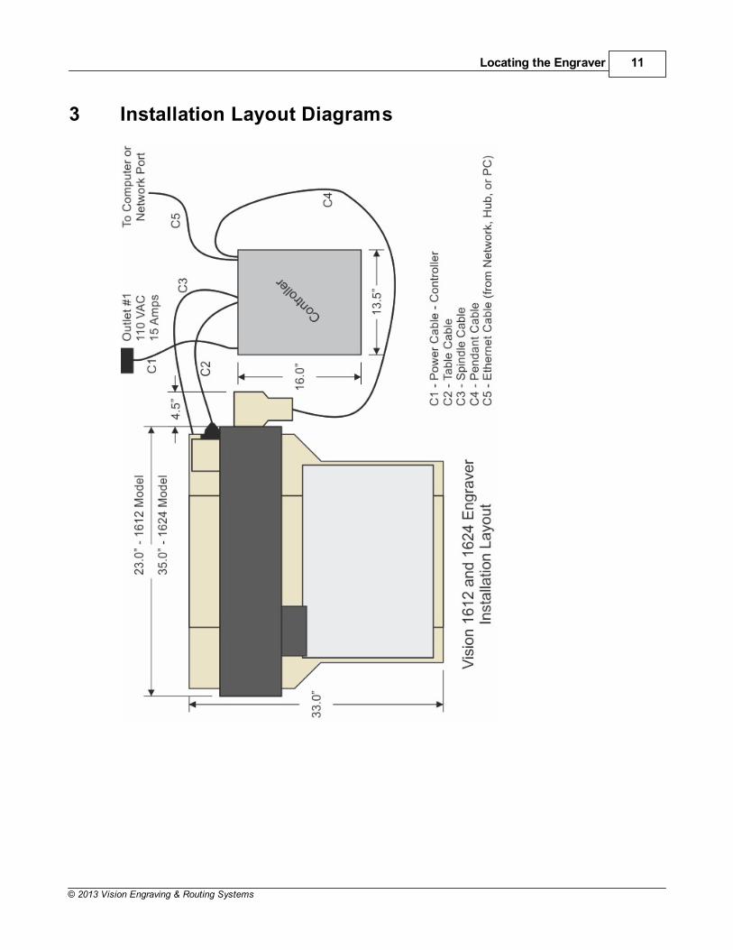
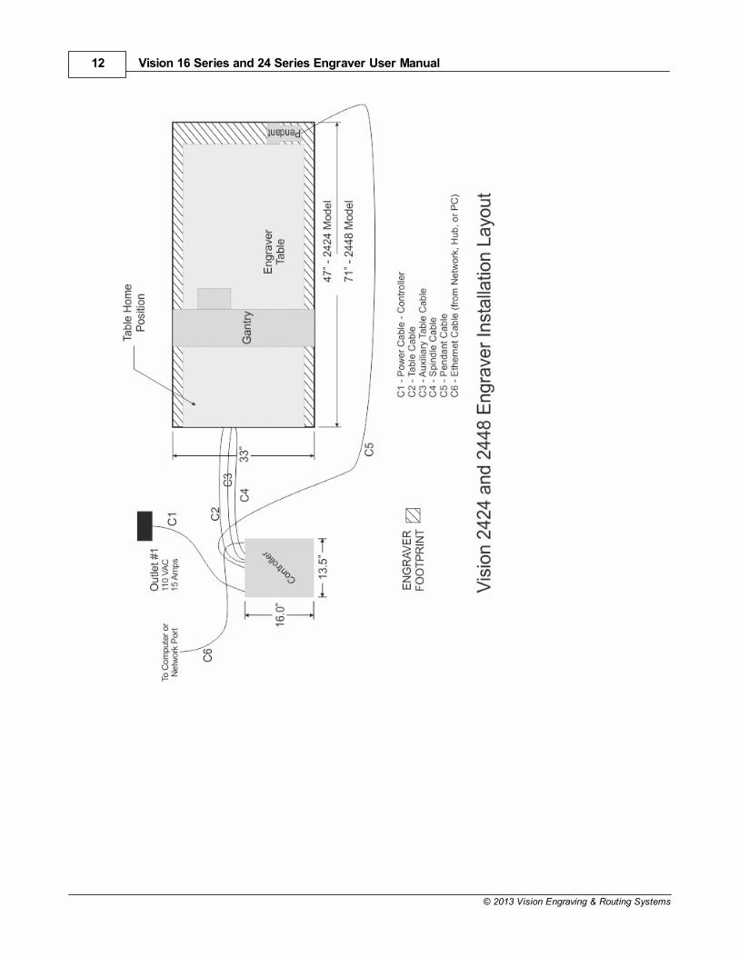
3 Installation Layout Diagrams
Vision 16 Series and 24 Series Engraver User Manual12
© 2013 Vision Engraving & Routing Systems

Installation Layout Diagrams 13
© 2013 Vision Engraving & Routing Systems
4 Table Descriptions
16 Series Engraver Descriptions(Refer to the diagrams on the following page)
1. Table Base Plate. This is the large flat plate upon which everything else is mounted.All mechanical alignments are referenced to this plate, so the space upon which you place theengraving table must be a reasonably level surface.
2. Y-Axis Linear Rails. Mounted on the table base plate are stainless steel rails with sealed bearings,which allow the motion of the T-slot table in the Y-axis direction.
3. T-Slot Table. Also referred to as the work surface, this aluminum bed supported by the linear railsallows placement of the engraving material or special clamps and fixtures. The slots in this table areshaped with an upside-down T, with the bottom of the T being a single-line slot across the top of thetable. The slots are used to hold various accessory holders, clamps, and jigs. All t-slot accessories areavailable on at www.visionengravers.com
4. Y-Axis Lead Screw. This is a threaded rod located underneath the T-slot table. Combined with thestepper motor, the lead screw is rotated and causes the T-slot table to move along the rails in the Y-axisdirection. There is also a second lead screw called the X-axis lead screw. The X-axis lead screw iscontained within the gantry, and can be accessed by removing the black sheet metal gantry cover. TheX-axis lead screw is responsible for X-axis motion of the carriage assembly, moving it left and rightacross the gantry.
5. Gantry Assembly. The gantry or “bridge” is a large, rectangular bar suspended across the width ofthe table in the X-axis. The carriage assembly is supported and rides on the gantry in the X-axis.
6. Carriage Assembly. The carriage assembly houses the engraving spindle, Z-Axis mechanism andengraving motor. The carriage moves along the gantry assembly on a set of sealed bearing. Thecarriage assembly holds the engraving spindle; it raises and lowers the spindle during the engravingprocess using a lead screw and stepper motor.
7. 25 Pin Connector. This connection port is used to connect the table to the system controller. Theconnector is located near the rear of the table and on top of the base plate.
8. Y-Axis Stepper Motor. Drives the T-Slot table in the Y-Axis.
9. X-Axis Stepper Motor. Drives the carriage in the X-Axis. Located under the protective cover.
10. Edge Guides. Used as a back and side stop for locating material and clamps during set-up.
11. Engraving Motor. The engraving motor or “spindle motor”, is the large black motor on the top of thecarriage assembly. The engraving motor drives a belt and pulley system, which turns the engravingcutter during the engraving process.
12. Spindle Cable. Connects to the system controller and provides power to the engraving motor.
13. Quick Lock Vise. A “cam” type locking device that allows quick change of parts for engraving.

Vision 16 Series and 24 Series Engraver User Manual14
© 2013 Vision Engraving & Routing Systems
Typical 16 Series Engraver Diagrams
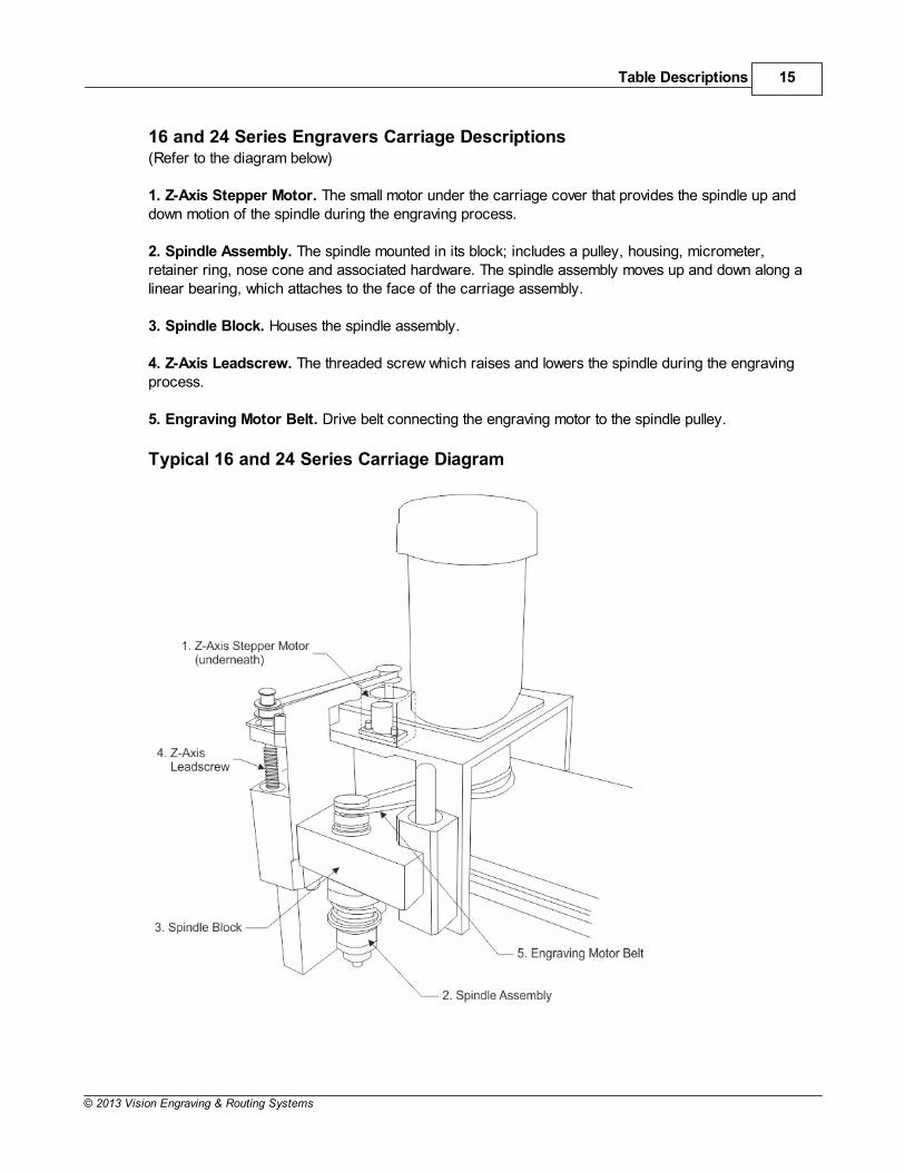
Table Descriptions 15
© 2013 Vision Engraving & Routing Systems
16 and 24 Series Engravers Carriage Descriptions(Refer to the diagram below)
1. Z-Axis Stepper Motor. The small motor under the carriage cover that provides the spindle up anddown motion of the spindle during the engraving process.
2. Spindle Assembly. The spindle mounted in its block; includes a pulley, housing, micrometer,retainer ring, nose cone and associated hardware. The spindle assembly moves up and down along alinear bearing, which attaches to the face of the carriage assembly.
3. Spindle Block. Houses the spindle assembly.
4. Z-Axis Leadscrew. The threaded screw which raises and lowers the spindle during the engravingprocess.
5. Engraving Motor Belt. Drive belt connecting the engraving motor to the spindle pulley.
Typical 16 and 24 Series Carriage Diagram

Vision 16 Series and 24 Series Engraver User Manual16
© 2013 Vision Engraving & Routing Systems
24 Series Engraver Descriptions(Refer to the Diagrams on the following page)
1. Table Base Plate. This is the large flat plate upon which everything else is mounted. All mechanicalalignments are referenced to this plate, so the space upon which you place the engraving table must bea reasonably level surface.Always carry the table by the base plate only. An optional t-slot table may be installed on the table baseplate.
2. X-Axis Linear Rails. Mounted under the table base plate are steel rails with sealed bearings, whichallow the motion of the gantry in the X-axis direction.
3. X-Axis Leadscrews. This are the threaded rods located underneath the table baseplate. Combinedwith the stepper motors, the leadscrews are rotated and cause the gantry to move along the rails in theX-axis direction. There is also a second leadscrew in the Y-axis of the machine. The Y-axis leadscrewis contained within the gantry and can be accessed by removing the black sheet metal gantry cover.The Y-axis leadscrew is responsible for motion of the carriage assembly, moving it back and forthacross the gantry.
4. Gantry Assembly. The gantry or “bridge” is a large, rectangular bar suspended across the width ofthe table. It travels down the table along the X-axis.
5. Carriage Assembly. The carriage assembly houses the engraving spindle, the Z-axis mechanismand the engraving motor. The carriage moves along the gantry assembly on a set of sealed bearings inthe Y-axis. The carriage assembly raises and lowers the engraving spindle during the engravingprocess using the Z-Axis leadscrew and stepper motor.
6. 25 Pin Connector. This connector port is used to connect the table to the system controller.
7. Y-Axis Stepper Motor. Drives the carriage in the Y-Axis.
8. X-Axis Stepper Motors. Drives the gantry in the X-Axis.
9. Edge Guides. Used as a back and side stop for accurately locating material and clamps during set-up.
10. Engraving Motor. Drives the spindle for rotary engraving.
11. Serial Connector. This connector port is used to connect the table to the controller.
12. DACS USB Connector. This optional connector is used to connect the DACS Camera System toyour computer.
13. Spindle Cable. This cable connects to the system controller and provides power to the engravingmotor.
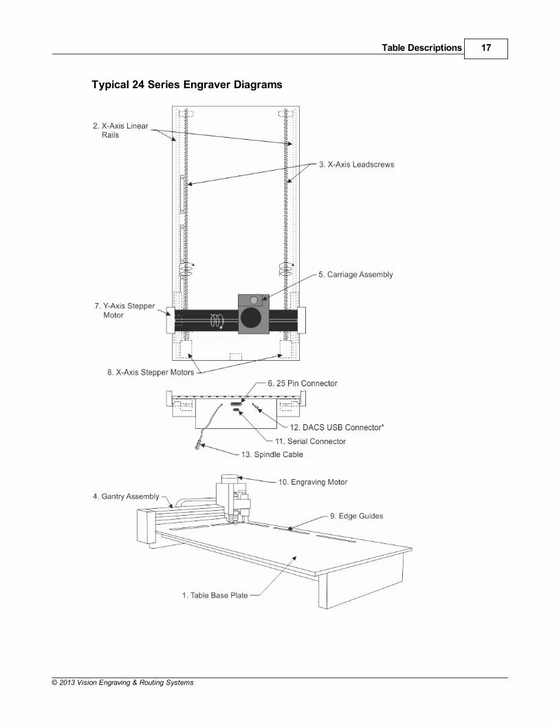
Table Descriptions 17
© 2013 Vision Engraving & Routing Systems
Typical 24 Series Engraver Diagrams
Vision 16 Series and 24 Series Engraver User Manual18
© 2013 Vision Engraving & Routing Systems
5 Table Connections
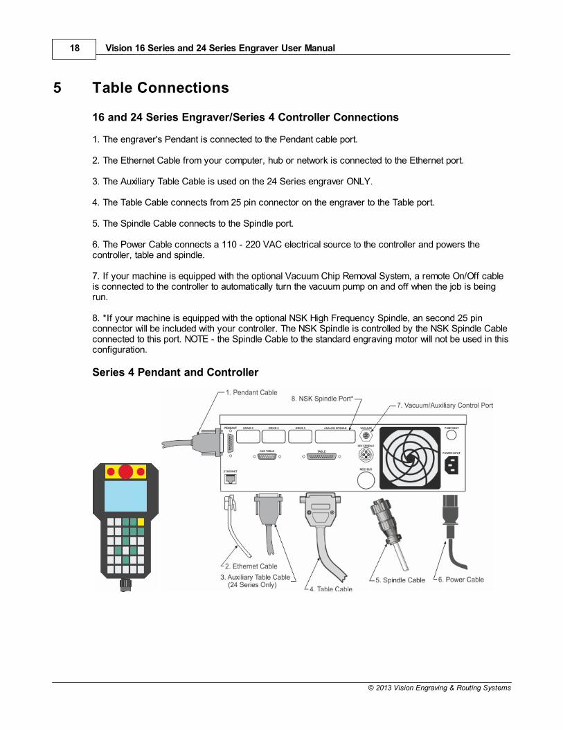
16 and 24 Series Engraver/Series 4 Controller Connections
1. The engraver's Pendant is connected to the Pendant cable port.
2. The Ethernet Cable from your computer, hub or network is connected to the Ethernet port.
3. The Auxiliary Table Cable is used on the 24 Series engraver ONLY.
4. The Table Cable connects from 25 pin connector on the engraver to the Table port.
5. The Spindle Cable connects to the Spindle port.
6. The Power Cable connects a 110 - 220 VAC electrical source to the controller and powers thecontroller, table and spindle.
7. If your machine is equipped with the optional Vacuum Chip Removal System, a remote On/Off cableis connected to the controller to automatically turn the vacuum pump on and off when the job is beingrun.
8. *If your machine is equipped with the optional NSK High Frequency Spindle, an second 25 pinconnector will be included with your controller. The NSK Spindle is controlled by the NSK Spindle Cableconnected to this port. NOTE - the Spindle Cable to the standard engraving motor will not be used in thisconfiguration.
Series 4 Pendant and Controller
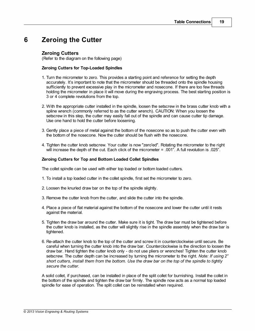
Table Connections 19
© 2013 Vision Engraving & Routing Systems
6 Zeroing the Cutter
Zeroing Cutters(Refer to the diagram on the following page)
Zeroing Cutters for Top-Loaded Spindles
1. Turn the micrometer to zero. This provides a starting point and reference for setting the depthaccurately. It’s important to note that the micrometer should be threaded onto the spindle housingsufficiently to prevent excessive play in the micrometer and nosecone. If there are too few threadsholding the micrometer in place it will move during the engraving process. The best starting position is3 or 4 complete revolutions from the top.
2. With the appropriate cutter installed in the spindle, loosen the setscrew in the brass cutter knob with aspline wrench (commonly referred to as the cutter wrench). CAUTION: When you loosen thesetscrew in this step, the cutter may easily fall out of the spindle and can cause cutter tip damage.Use one hand to hold the cutter before loosening.
3. Gently place a piece of metal against the bottom of the nosecone so as to push the cutter even withthe bottom of the nosecone. Now the cutter should be flush with the nosecone.
4. Tighten the cutter knob setscrew. Your cutter is now "zero'ed". Rotating the micrometer to the rightwill increase the depth of the cut. Each click of the micrometer = .001”. A full revolution is .025”.
Zeroing Cutters for Top and Bottom Loaded Collet Spindles
The collet spindle can be used with either top loaded or bottom loaded cutters.
1. To install a top loaded cutter in the collet spindle, first set the micrometer to zero.
2. Loosen the knurled draw bar on the top of the spindle slightly.
3. Remove the cutter knob from the cutter, and slide the cutter into the spindle.
4. Place a piece of flat material against the bottom of the nosecone and lower the cutter until it restsagainst the material.
5. Tighten the draw bar around the cutter. Make sure it is tight. The draw bar must be tightened beforethe cutter knob is installed, as the cutter will slightly rise in the spindle assembly when the draw bar istightened.
6. Re-attach the cutter knob to the top of the cutter and screw it in counterclockwise until secure. Becareful when turning the cutter knob into the draw bar. Counterclockwise is the direction to loosen thedraw bar. Hand tighten the cutter knob only - do not use pliers or wrenches! Tighten the cutter knobsetscrew. The cutter depth can be increased by turning the micrometer to the right. Note: If using 2”short cutters, install them from the bottom. Use the draw bar on the top of the spindle to tightlysecure the cutter.
A solid collet, if purchased, can be installed in place of the split collet for burnishing. Install the collet inthe bottom of the spindle and tighten the draw bar firmly. The spindle now acts as a normal top loadedspindle for ease of operation. The split collet can be reinstalled when required.
Vision 16 Series and 24 Series Engraver User Manual20
© 2013 Vision Engraving & Routing Systems
Tightening the CutterKnob into the Draw Barof a Collet Spindle
Zeroing the Cutter 21
© 2013 Vision Engraving & Routing Systems
7 Proximity Sensor
Advantage of this Feature
The advantage of this device is that it eliminates the need to perform a surface setting procedure. It isused when utilizing a nose cone or diamond drag cutter. It cannot be used without a nose cone, suchas when burnishing or setting multiple pass depths in the software.
Procedure
1. Make sure that the proximity switch is in the “On” position on the controller's Pendant, or turned onwithin the Vision software. Ensure that some travel is allowed to “float” the spindle on the pressurespring. The pressure spring adjuster must be backed off.
2. Zero the cutter in the spindle and dial in the desired depth on the nose cone micrometer.3. Send the job to the controller via the computer.4. Press the “Start” button on the Pendant to begin engraving.
Usage
“Nose-riding” - WITH proximity sensor
Engraving with the proximity sensor can only be performed with a nose cone attached, or whendiamond drag engraving.
“Non-nose-riding” - WITHOUT proximity sensor
When setting a depth in the Vision software, the proximity sensor should be turned off via the Pendant,or in the Cut Toolbox (in the Vision software program before sending the job to the machine). Also,make sure that there is no “float” on the spindle by locking the pressure spring adjuster all the waydown. Locking the spindle is especially important when engraving into hard surfaces or materials likebrass and stainless steel.
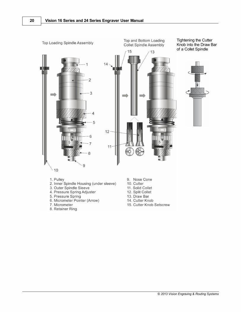
Diamond Drag Engraving
To install a diamond drag adapter, remove the retainer ring and nose cone from the bottom of thespindle and replace with the diamond drag adapter. For diamond drag engraving, the engraving motor isturned off and the cutter “drags” across the material. Down pressure against the material can bereduced or increased as necessary by adjusting the spring pressure adjuster as shown below.
Vision 16 Series and 24 Series Engraver User Manual22
© 2013 Vision Engraving & Routing Systems
8 Maintenance
Vision strives for the highest quality in their manufacturing process to provide you with the mostcost effective, reliable engraving machine in use today. Please remember that propermaintenance and care is necessary to achieve maximum product life expectancy.
The engraving environment generates small plastic and metal chips as well as other particles duringoperation. As with any machinery, your engraving system should be kept as clean as possible tominimize wear and tear and to improve final quality of the engraved product.
Removing Chips
A portable vacuum is suggested for chip removal, but applying direct suction to the spindle area is notrecommended. Note that this cleaning can be minimized and greatly simplified through the use of theoptional vacuum chip removal system. The vacuum chip removal system removes chips and dustcreated by engraving. This system can also extend the life of other components in the system, asprompt removal of chips reduces contamination and overheating in the spindle area. The vacuum chipremoval system also keeps the nose cone from skipping over letters due to chips that would otherwiseremain on the engraving surface.
The Vacuum Chip Removal System
The optional vacuum chip removal system is designed to simplify the engraving process and minimizewear and tear on the engraver. The vacuum chip removal system uses a vacuum nose cone to removechips created during the engraving process before they have the chance to create problems. The quietpump, coupled with the micro-fine layered filters, assures that your unwanted chips are whisked awayeffortlessly. The vacuum pump canister uses reusable filters to assure maximum efficiency and cost-effectiveness.
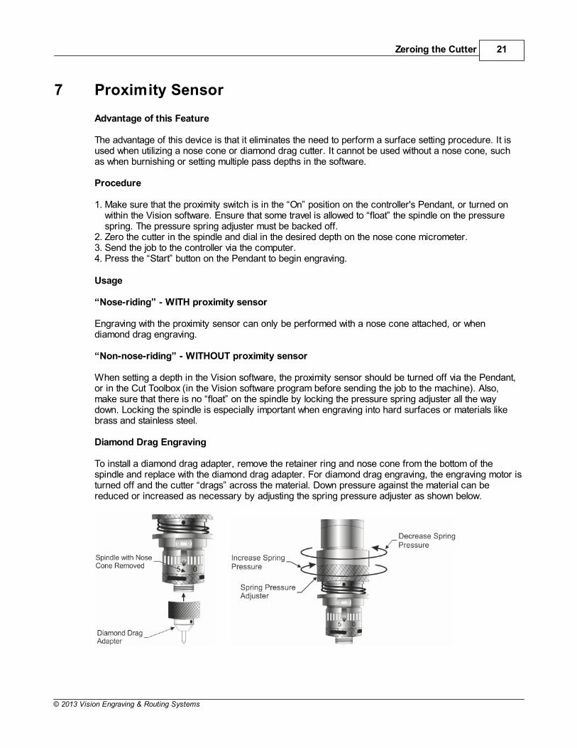
Engraving Motor Belt Replacement
A belt is used to drive the engraver's spindle. Itruns between the motor drive pulley and thespindle pulley. If it needs replacement, removethe old belt by rolling it to the top of the spindlepulley, then slightly stretching the belt to snap itover the top of the spindle pulley. Once loose, itcan easily be removed from the machine. Toinstall the new belt, position the new belt aroundthe drive pulley, then lightly stretch it to snapover the top of the spindle pulley.
NOTE: Be sure to purchase the specifiedreplacement belt from Vision EngravingSystems. Having the correct belt size isextremely important to the functionality of themotor. NEVER EXCESSIVELY STRETCH THEBELT!
Maintenance 23
© 2013 Vision Engraving & Routing Systems
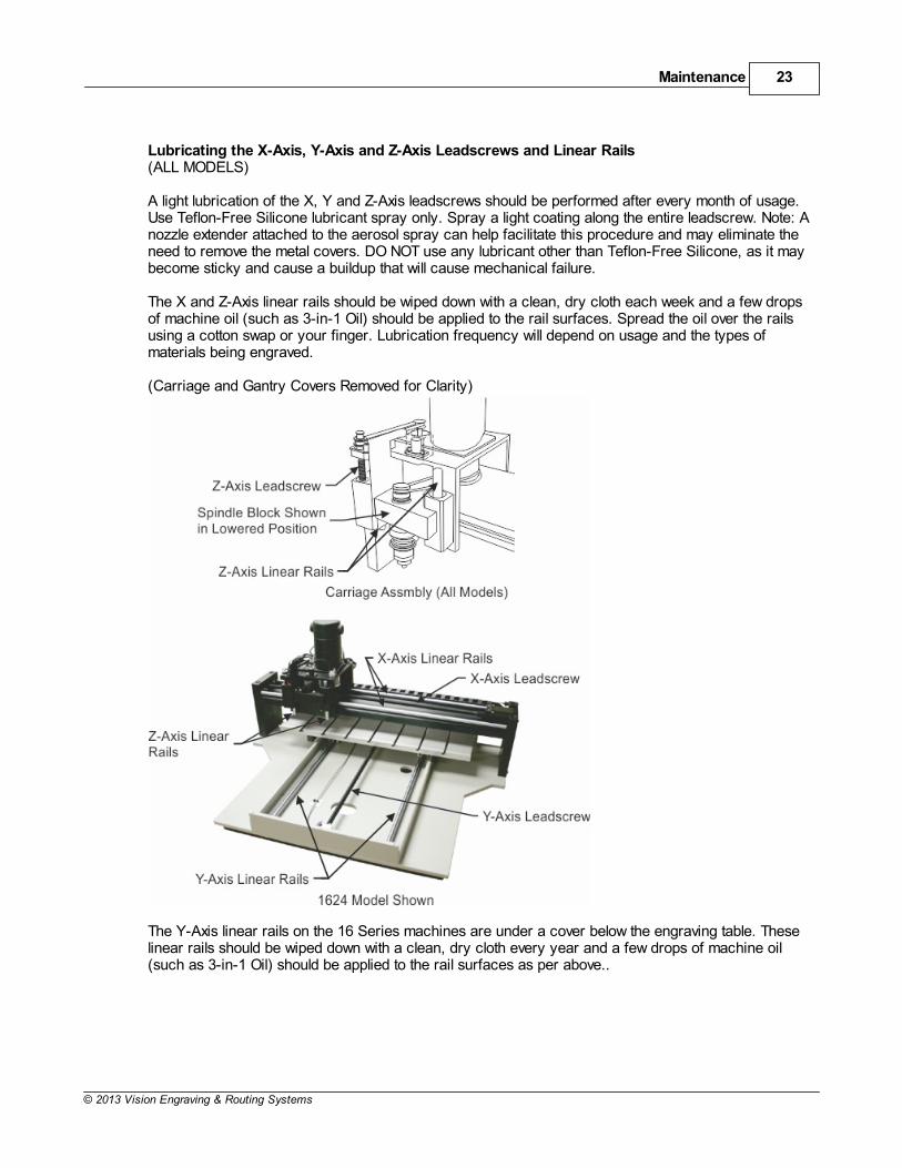
Lubricating the X-Axis, Y-Axis and Z-Axis Leadscrews and Linear Rails(ALL MODELS)
A light lubrication of the X, Y and Z-Axis leadscrews should be performed after every month of usage.Use Teflon-Free Silicone lubricant spray only. Spray a light coating along the entire leadscrew. Note: Anozzle extender attached to the aerosol spray can help facilitate this procedure and may eliminate theneed to remove the metal covers. DO NOT use any lubricant other than Teflon-Free Silicone, as it maybecome sticky and cause a buildup that will cause mechanical failure.
The X and Z-Axis linear rails should be wiped down with a clean, dry cloth each week and a few dropsof machine oil (such as 3-in-1 Oil) should be applied to the rail surfaces. Spread the oil over the railsusing a cotton swap or your finger. Lubrication frequency will depend on usage and the types ofmaterials being engraved.
(Carriage and Gantry Covers Removed for Clarity)
The Y-Axis linear rails on the 16 Series machines are under a cover below the engraving table. These linear rails should be wiped down with a clean, dry cloth every year and a few drops of machine oil(such as 3-in-1 Oil) should be applied to the rail surfaces as per above..
Vision 16 Series and 24 Series Engraver User Manual24
© 2013 Vision Engraving & Routing Systems
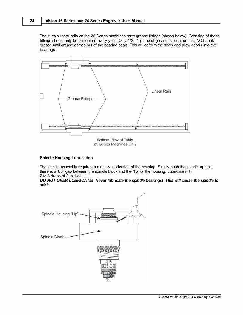
The Y-Axis linear rails on the 25 Series machines have grease fittings (shown below). Greasing of thesefittings should only be performed every year. Only 1/2 - 1 pump of grease is required. DO NOT applygrease until grease comes out of the bearing seals. This will deform the seals and allow debris into thebearings.
Spindle Housing Lubrication
The spindle assembly requires a monthly lubrication of the housing. Simply push the spindle up untilthere is a 1/3” gap between the spindle block and the “lip” of the housing. Lubricate with2 to 3 drops of 3 in 1 oil.DO NOT OVER LUBRICATE! Never lubricate the spindle bearings! This will cause the spindle tostick.
Maintenance 25
© 2013 Vision Engraving & Routing Systems
What not to Lubricate
Many of the bearings and assemblies in your engraving machine are sealed and/or coated usingspecial low-friction methods and should not be lubricated. Do not not attempt to lubricate the spindlebearings. If you suspect lubrication problems, call Vision for instructions, as further lubrication mayharm the machine. Do not not lubricate the X or Y stepper motors.
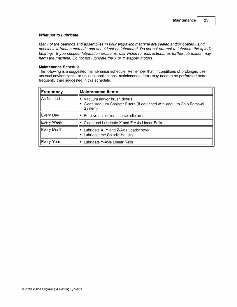
Maintenance ScheduleThe following is a suggested maintenance schedule. Remember that in conditions of prolonged use,unusual environments, or unusual applications, maintenance items may need to be performed morefrequently than suggested in this schedule.
Frequency Maintenance Items
As Needed Vacuum and/or brush debrisClean Vacuum Canister Filters (if equipped with Vacuum Chip RemovalSystem)
Every Day Remove chips from the spindle area
Every Week Clean and Lubricate X and Z-Axis Linear Rails
Every Month Lubricate X, Y and Z-Axis LeadscrewsLubricate the Spindle Housing
Every Year Lubricate Y-Axis Linear Rails
Vision 16 Series and 24 Series Engraver User Manual26
© 2013 Vision Engraving & Routing Systems
9 Riser Block Extensions
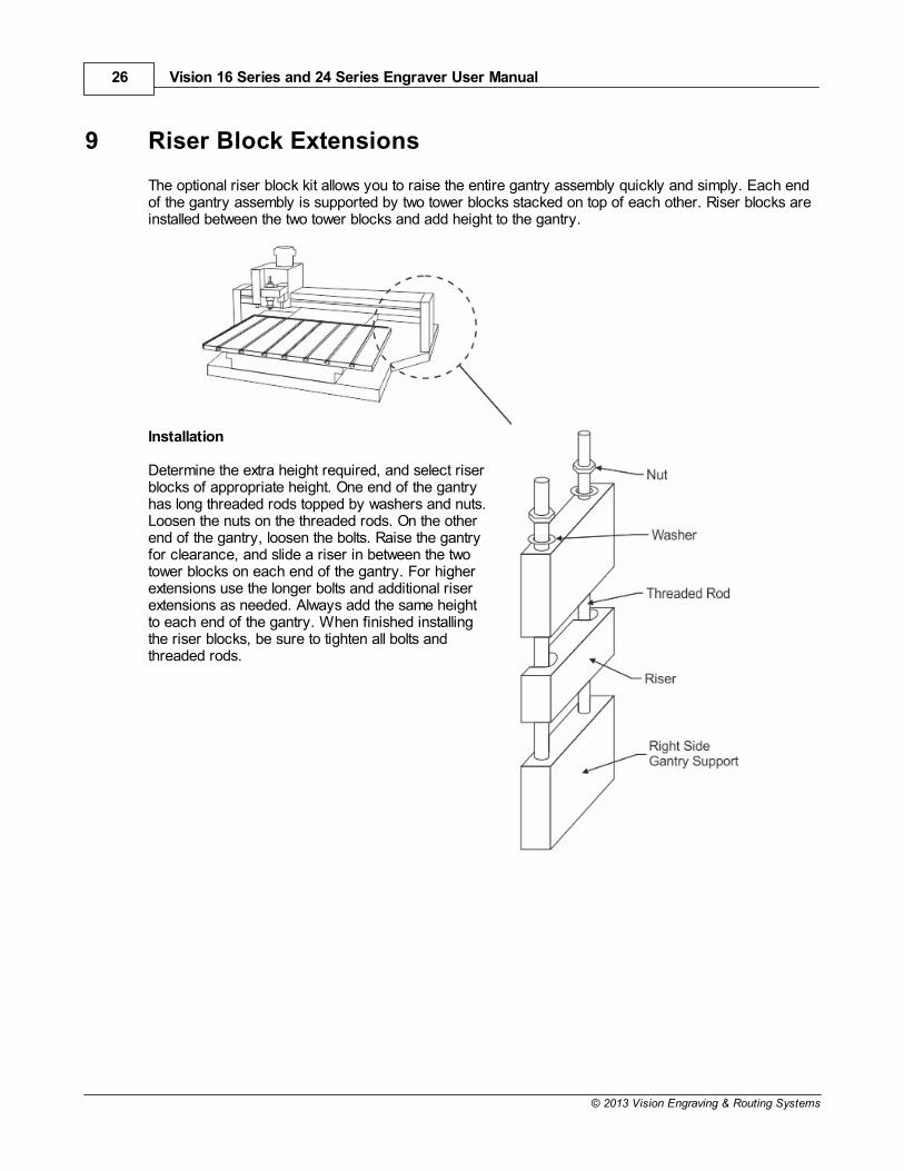
The optional riser block kit allows you to raise the entire gantry assembly quickly and simply. Each endof the gantry assembly is supported by two tower blocks stacked on top of each other. Riser blocks areinstalled between the two tower blocks and add height to the gantry.
Installation
Determine the extra height required, and select riserblocks of appropriate height. One end of the gantryhas long threaded rods topped by washers and nuts.Loosen the nuts on the threaded rods. On the otherend of the gantry, loosen the bolts. Raise the gantryfor clearance, and slide a riser in between the twotower blocks on each end of the gantry. For higherextensions use the longer bolts and additional riserextensions as needed. Always add the same heightto each end of the gantry. When finished installingthe riser blocks, be sure to tighten all bolts andthreaded rods.
Riser Block Extensions 27
© 2013 Vision Engraving & Routing Systems
10 Collets and Diamond Drag Adapter
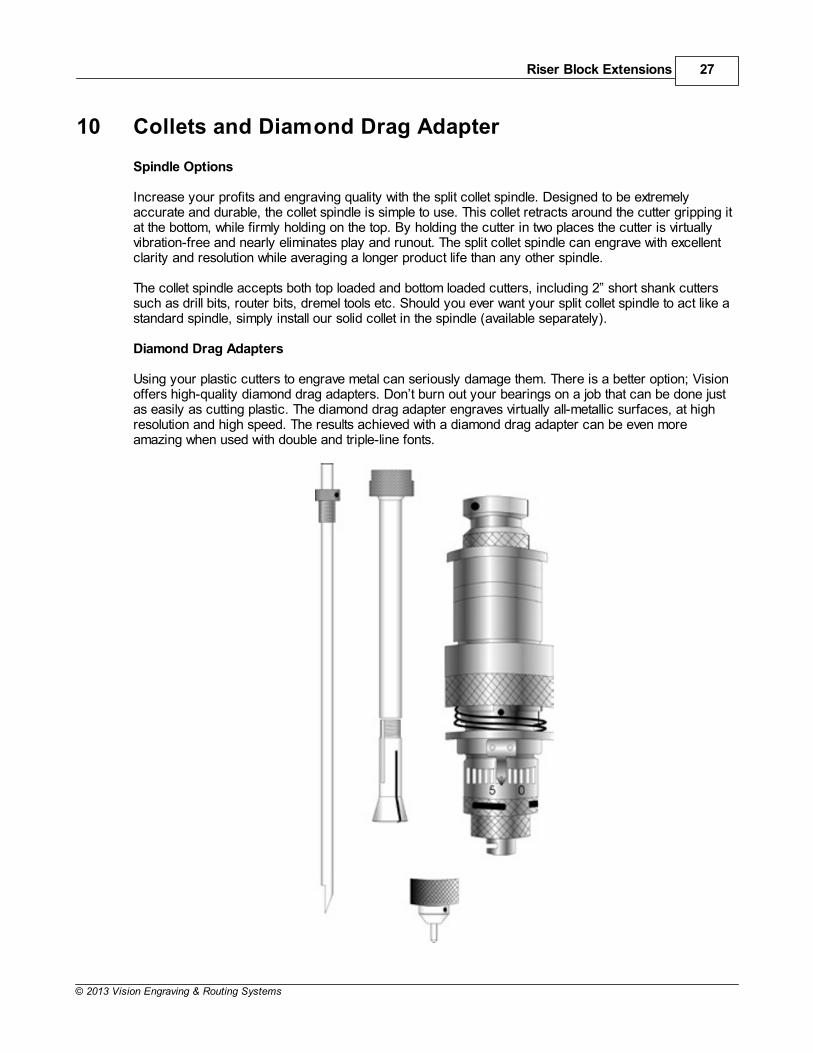
Spindle Options
Increase your profits and engraving quality with the split collet spindle. Designed to be extremelyaccurate and durable, the collet spindle is simple to use. This collet retracts around the cutter gripping itat the bottom, while firmly holding on the top. By holding the cutter in two places the cutter is virtuallyvibration-free and nearly eliminates play and runout. The split collet spindle can engrave with excellentclarity and resolution while averaging a longer product life than any other spindle.
The collet spindle accepts both top loaded and bottom loaded cutters, including 2” short shank cutterssuch as drill bits, router bits, dremel tools etc. Should you ever want your split collet spindle to act like astandard spindle, simply install our solid collet in the spindle (available separately).
Diamond Drag Adapters
Using your plastic cutters to engrave metal can seriously damage them. There is a better option; Visionoffers high-quality diamond drag adapters. Don’t burn out your bearings on a job that can be done justas easily as cutting plastic. The diamond drag adapter engraves virtually all-metallic surfaces, at highresolution and high speed. The results achieved with a diamond drag adapter can be even moreamazing when used with double and triple-line fonts.

Vision 16 Series and 24 Series Engraver User Manual28
© 2013 Vision Engraving & Routing Systems
11 Troubleshooting
ENGRAVING PROBLEMS
Problem: Engraving on the plate is “slanted”.
Possible solutions:1. Check material for squareness. Is the material cut square?2. Check to see if the material on the table is square to the home position and the edge guides.Hint: Always inspect your job before removing your plate from the system. You may be able to salvage itby re-engraving the job, or at a minimum, you may be able to analyze the problem and preventrepeating it. Perhaps the plate moved during engraving. Removing it without inspection would preventyou from detecting this problem.
Problem: You are using a nosecone, but your engraving is “shallow” across the top or leftmargin of your plate. It engraves properly when the spindle is away from the edge.
Possible solutions:1. Your nosecone is riding on the edge guides. Lower the edge guides so that they are even with orbelow the level of your material surface. 2. Check to see if your material is on top of the edge guides.
Problem: You are using a nosecone and your engraving is uneven.
Possible solutions:1. Your spindle is not “zeroed” to your material. 2. You are not using enough enough spring pressure to keep the nosecone in contact with the material.3. You may be engraving too fast for the type of material you are cutting. Check the manufacturer’srecommendation. The cutter may be bouncing on the surface. Some hard materials may exhibit thisproblem.4. You may have a defective or broken cutter.5. Your material may be defective.6. Your vacuum chip removal system is plugged and engraving chips are getting caught between thenosecone and the material.7. The nosecone or vacuum nosecone is loose.
Problem: “Shadowing” occurs while engraving certain materials.
Possible solutions:1. Leave the protective film on the engraving material during engraving.2. Use a plastic nosecone instead of a standard metal nosecone.3. The nosecone may be damaged. Inspect for burrs or roughness. Try using an Emory cloth to polishthe nose.4. Back off on the spring pressure. Excessive down pressure will leave a rub mark on almost any plasticmaterial.
Problem: You are not using a nosecone and you have uneven engraving.
Possible solutions:1. Switch to a nose-riding method.2. Use a different method of holding the material. If you use double sided tape, it may be thick enoughto change your surface flatness by a few thousandths.3. Parcel the job if possible so that you can have more direct control over the depth of each specificarea. This may be effective if you have uneven material or a large engraving bed.
Troubleshooting 29
© 2013 Vision Engraving & Routing Systems
4. Table tolerances may not be able to maintain the accuracy level you want.5. Table may not be on a level surface.Hint: While it’s true that you can do non-nose riding engraving, it’s not easy to hold any controlledaccuracy on the depth. This takes flat material, a very flat bed and some degree of skill and confidence.It also takes an application where some amount of uneven engraving may be tolerated.
Problem: I’m getting “tails” or “swirls” in the corners of my engraving.
Possible solutions:1. Your cutter speed is too fast relative to your x-y speed. Slow your spindle speed down or increaseyour table speed.2. Your cutter is worn or damaged.3. Turn down the dwell speed.
Problem: I’m getting “fuzz”, “fur” or can see lines in the bottom of my cut showing each cutterpath. I can even see steps in the bottom of my cut.
Possible solutions:1. This problem is tough. Sometimes caused by dull cutters, the wrong cutter, or not enough overlap foreach cut. Try changing cutter size slightly. You may get better clean up.2. Try taking a second pass cut at .001-.002 deeper. This may clean up the roughness.3. Resharpen the cutter. There are various cutter angles that can cause these kinds of problems. Thereis a relief angle that if too great can cause noticeable ridges in the bottom of the cut.4. Ensure that the spindle is square in the mount or block. An unsquare spindle means an unsquarecutter to the material surface.5. Turn spindle speed up.
Problem: Poor letter quality.
Possible solutions:1. You may be engraving too fast. Engraving quality improves with the right engraving and spindlespeeds.2. If you are diamond drag engraving, you have too much down pressure or you are engraving toodeep. Also, check the grain of the material; it should be left to right.3. You may have a worn or dull cutter.4. Your material is not securely fastened to the table.
Problem: Ragged Type.
Possible solutions:1. If the quality of cut is ragged or exhibits steps, you may have play in the cutter. This could be in thegap between the cutter and the spindle shaft. Maybe the shaft is worn or the spindle bearings need tobe replaced. Once a shaft starts to wear and a cutter is loose, the problem can worsen quickly.2. The spindle is loose in the housing or block.3. The carriage is loose or has excessive play, check the z-axis bearings or slide.4. Lubricate lead screws with recommended lubricant.
Problem: My baseline is off.
Possible solutions:1. You’re not at the mechanical or software home. Maybe the table or carriage was bumped during set-up. Maybe the previous job was cut short and the system did not return back to its mechanical home orlimit switches. Move the table, bridge or carriage physically to home or send it home via the software.2. Check your software layout for keystroke errors.

Vision 16 Series and 24 Series Engraver User Manual30
© 2013 Vision Engraving & Routing Systems
Problem: While burnishing aluminum I have voids or non-engraved areas.
Possible solutions:1. Try re-engraving the same plate again. Some of the anodized aluminum plates have very hardsurfaces and two passes are required.2. Switch to a diamond burnisher. The more common carbide tools may have difficulty getting throughthe tough surface and are more easily worn down, thus sometimes skipping across the surface.3. Increase the pressure of the z-axis or burnishing adapter.4. Try other materials. Same reasons as above. Some materials, from some vendors, are just plaintough.
Hints:Always try to solve the problems yourself before seeking help. A little patience goes a long way. Neverwork on any problem that gets you so frustrated that you become irritated at the machine, the servicetechnician, or the salesman. It’s only a machine, don’t let it get the best of you. Contact your dealer.
MECHANICAL PROBLEMS
Problem: No X, Y or Z-Axis movement.
Possible solutions:1. Check that the controller power is on.2. Check that the drives are turned on.3. Check the table cable for a solid connection. It may be helpful to remove the cable, reconnect andtighten the hold down screws to ensure a good connection.4. Ensure that the job has been transferred to the controller.5. Ensure that the emergency STOP button is not depressed.
Problem: System has no movement in any one axis.
Possible solutions:1. Try to jog the problem axis using the X/Y/Z jog keys on the control unit. If OK, retry the job.2. Check the table cable for a solid connection.3. Call service technician for further instructions.
Problem: Unusually loud noises during the engraving process.
Possible solutions:1. Isolate the cause of the unusual noise by:
a. Remove the cutter.b. Turn the engraving motor to OFF.c. Run the engraving job, or X/Y jog the system.
If the noise persists, it may be confined to the X, Y or Z-axis. Check for proper lubrication ofleadscrews. If the noise goes away and to further isolate the cause, do the following:
a. Remove the motor belt.b. Run the engraving motor without starting a job. Loose motor belts may cause some noises,
so removal will narrow down the problem. If the noise is present with the spindle motor on, check themotor brushes.If there is no unusual noise when running the spindle motor with no belt attached, do the following:
a. Attach the motor belt.b. Run the spindle motor and vary the RPM with the Pendant control.
Noise levels may vary. If the noise persists, check the spindle for overheating. Excessive overheating ofthe outside housing of the spindle is a sign of defective bearings. The noise may be caused by thebearings.
Troubleshooting 31
© 2013 Vision Engraving & Routing Systems
Problem: Spindle is hot.
Possible solutions:1. Ensure that the nose cone area is free of debris. Check the vacuum system (if used) for clogging.2. Inspect the spindle for other obstructions that may prevent proper rotation.3. Bearings may need to be replaced.
Problem: Spindle motor will not turn on.
Possible solutions:1. Check the auto/on/off switch to ensure the proper operational mode.2. Check motor brushes.
Problem: Motor belt will not stay on pulley.
Possible solutions:1. Motor belt is probably worn and needs to be replaced.


