Page 1
ii
ABSTRACT
Visual Cryptography is a technique, which is used to conceal the secret image into
transparencies (which will vary with the user) and these transparencies are distributed to the
intended recipients. In Extended Visual Cryptography Scheme, the transparencies are embedded
into the meaningful images so that the intended recipient will have a transparency, which is a
meaningful image. Without much computation, only the qualified set of participants can reveal
the secret image by simply stacking transparencies. The tool can be used in both ways, to encrypt
the secret image into transparencies and also to decrypt the embedded images. Simple steps and
operations perform encryption and decryption of images. Halftoning algorithm is used to divide
the secret image into transparencies with the help of dither matrix. Dither matrix stores the
information of all pixels in the secret image. Using this tool, user can send encrypted images that
are in the format of GIF and PNG. The encrypted transparencies can be saved in the machine
and can be sent to the intended person by other means. Experimental results reveal that the tool
works with gray-scale images in the format of .png and .gif.
Page 2
iii
TABLE OF CONTENTS
ABSTRACT………………………………………………………………………………………ii
TABLE OF CONTENTS………………………………………………………………………...iii
LIST OF FIGURES………………………………………………………………………………iv
1. Background and Rationale…………………………………………………………………….1
1.1 Visual Cryptography Scheme for Secret Hiding………………………………………….2
1.2 Halftone Visual Cryptography Via Error Diffusion………………………………………4
1.3 Sharing Multiple Secrets Using Visual Cryptography……………………………….……5
1.4 An Extended Visual Cryptography Algorithm for General Access Structures……...........6
1.5 Embedded Extended Visual Cryptography Schemes…………………………………..…8
2. Objective…………………………………………………………………………………..…..8
3. Implementation of EVCS Mechanism……………………………………………………..….9
3.1 Halftone technique using dither matrix………………………………………………..….9
3.2 Half toning process for each pixel i…………………………………………………..….10
3.3 Embedding Shares……………………………………………………………………….11
3.4 The Embedding Process……………………………………………………………….....12
4. System Design……………………………………………………………………………….13
4.1 System and Software Used in this project………………………………………………13
Page 3
iv
4.2 System Requirements………………………………………………………………….....14
4.3 User Interface Design…………………………………………………………………....14
4.3.1 Main Window……………………………………………………………………14
4.3.2 Visual Cryptography Window…………………………………………………...14
4.3.3 Embedding Window……………………………………………………………..15
4.4 Software Engineering Techniques……………………………………………………….15
4.4.1 Requirements…………………………………………………………………….15
4.4.1.1 Software Tools…………………………………………………………...15
4.4.1.2 Functional and Non-Functional Requirements…………………………..15
4.4.1.3 Structured Requirements..…………………………………………..........16
4.5 Analysis……………………………………………………………………………..........17
4.6 Design……………………………………………………………………………………18
5. Results and Testing….………………………………………………………………….........29
6. Conclusion…………………………………………………………………………………...71
7. Future Work………………………………………………………………………………….72
8. Bibliography and References………….………………………………….………………….73
Page 4
v
LIST OF FIGURES
Figure 1: Chang and Yu’s Secret Sharing Algorithm Flowchart…………....…………………….3
Figure 2: Example of halftone cells with size q=9 in a 3-out-of-3 scheme……………………….4
Figure 3: The secret image is encoded into two shares showing random patterns. The decoded
image shows the secret image……………………………………………………………………..5
Figure 4: Solution procedures for EVCS………………………………………………………….7
Figure 5: Traditional Halftone Transparencies…………………………………………………..10
a) 1st transparency.……………………………………………………………….10
b) 2nd transparency……………………………………………………………….10
c) Recovered image from transparency………………………………………….10
Figure 6: Embedding Algorithm Presentation…………………………………………………...13
Figure 7: Flow diagram of Halftone transparency generation…………………………………...18
Figure 8: Flow diagram of Halftone transparency embedding in original share images………...19
Figure 9: Flow diagram of Separation of embedded images and transparencies………………..20
Figure 10: Flow diagram of Halftone transparency selection and Viewing Knowledge………...21
Figure 11: Use-case diagram of User and System……………………………………………….22
Figure 12: Sequence Diagram of User and User Interface operations…………………………...23
Figure 13: Halftone transparencies generation sequence diagram………………………………24
Page 5
vi
Figure 14: Embedding process of half toned transparencies…………………………………….25
Figure 15: Separation of transparencies sequence diagram……………………………………...26
Figure 16: Visualization process sequence diagram……………………………………………..27
Figure 17: Component diagram of system components…………………………………………28
Figure 18: Main window screen…………………………………………………………………29
Figure 19: Visual Cryptography window………………………………………………………..30
Figure 20: Loading gray scaled image…………………………………………………………...31
Figure 21: Mode of operation to select number of transparencies………………….……………32
Figure 22: Generating operation of halftone images…………………………………………….34
Figure 23: Save all transparencies screen………………………………………………………..36
Figure 24: Location selection of transparencies to save…………………………………………37
Figure 25: Embedding window for embed operations…………………………………………..38
Figure 26: Select transparency from saved location……………………………………………..40
Figure 27: Select the original share image……………………………………………………….41
Figure 28: Real share image selection window………………………………………………….42
Figure 29: Giving Storage path to the embed image…………………………………………….43
Figure 30: Embedding operation result………………………………………………………….44
Page 6
vii
Figure 31: Separating window open file…………………………………………………………46
Figure 32: Giving absolute path………………………………………………………………….47
Figure 33: Result of the separated transparency…………………………………………………49
Figure 34: Selecting Transparencies from extracted embedded images into Visual Cryptography
window…………………………………………………………………………………………...50
Figure 35: Selecting saved transparency…………………………………………………………51
Figure 36: The encrypted transparencies view……………………………………………..........52
Figure 37: Selecting overlay transparency among the transparencies…………………………...53
Figure 38: Visualizing the complete knowledge by selecting all overlay transparencies……….54
Figure 39: Encrypted transparencies………..……………………………………………………58
Figure 40: Overlay transparency viewing………………………………………………………..59
Figure 41: Selection of more than one transparency…………………………………………….60
Figure 42: Complete overlay transparency images………………………………………............61
Figure 43: Selecting Valid Transparencies………………………………………………............62
Figure 44: Valid Transparency loading………………………………………………………….63
Figure 45: Complete overlay transparency images………………………………………………64
Figure 46 Error message on selecting the natural image………………………………………...65
Figure 47: Generating color image transparency………………………………………………...66
Page 7
viii
Figure 48: Generating gray level image transparency…………………………………………...67
Figure 49: Successful transparency embedding in original image………………….…………...68
Figure 50: Validation of Original image for embedding transparency………………………..…69
Figure 51: Validation of Absolute path……………………………………………….…………70
Page 8
1
1. Background and Rationale
The principle of visual cryptography scheme (VCS) was first introduced by Naor and Shamir.
VCS is for sharing secret information that focuses on sharing secret images. In the proposed
mechanism, using visual cryptography scheme, the idea is to split a secret image into two
random shares (printed on transparencies), where individual transparencies reveal no information
about the secret image other than the size of the secret image. The secret image can be
reconstructed by stacking the two shares. The underlying operation of this scheme is logical
operation. Traditional VCS takes a secret image as input, and outputs shares that satisfy two
conditions:
1) Minimum number of shares can recover the secret image, these shares are qualified shares.
2) Other than qualified subset of shares, no other shares can produce or reveal the secret image
other than size of the original image.
VCS recovers the secret image from qualified subset of shares. In this scheme, shares are
distributed to two participants secretly, and each participant cannot get any information about the
secret image, but after stacking shares, the secret image can be observed visually by the
participants. VCS can be used in military for soldiers who doesn’t have the knowledge of
cryptography and don’t have any devices to compute the secrets. There are many other
applications existing other than the VCS original purpose, those are, password sharing, secret
information sharing, watermarking and identification verification etc.
Page 9
2
1.1 Visual Cryptography Scheme for Secret Hiding
Using Visual cryptography, image is encrypted in such a way that no one apart from the sender
and intended recipient even realize the original image, this is a form of security through
obscurity. Cryptography hides the secret image in other images, but it does not reveal the fact
that it is not the actual image to others besides the sender and the recipient.
Based on cryptography, ‘n’ images are encoded and only the human naked eye can decrypt the
hidden message without any cryptographic computations. This is achieved when encrypted
image shares are stacked one over other using Visual Cryptography. An improved algorithm
based on Chang’s and Yu visual cryptography scheme is proposed to hide a colored image in the
form of multiple colored cover images as in fig-1 by computing F(ki, Ґp). As ‘I’ image encrypted
into ‘k’ number of shares and the function denotes each share by ki and Ґp is to perform the image
shared operation as in described in fig-1. Original image is encrypted into shares, and the shares
are also layered one after another to reveal secret image. Using ‘S’ matrix and the shares we
form original image without computation. This mechanism or approach results loss less recovery
and the noise reduction techniques are efficient enough in covering the images without adding
any computational complexity. This is the basic principle, which is developed for further
improvement of visual cryptography schemes.
Page 10
3
ki= S1 j XOR S2 j i if i< r --------[15]
where ki= S1 j XOR S2 j and j= i+1 if i>r
I O1 O2
k1k2
S2m
S1m
Fig 1: Chang and Yu’s secret sharing algorithm flowchart
1.2 Halftone Visual Cryptography via Error Diffusion
Naor proposed an algorithm for visual cryptography in which secret image is obtained by just
stacking shares without computation. Secret image is encoded into ‘n’ shares as shown in fig-2.
K1 K2 … K3
B1
B2
Ґp
generator
F(ki,Ґp)
Snm= S11 … S1
S21 … S2
Fill all the 1’s by k1
Fill all the 1’s by k2
Page 11
4
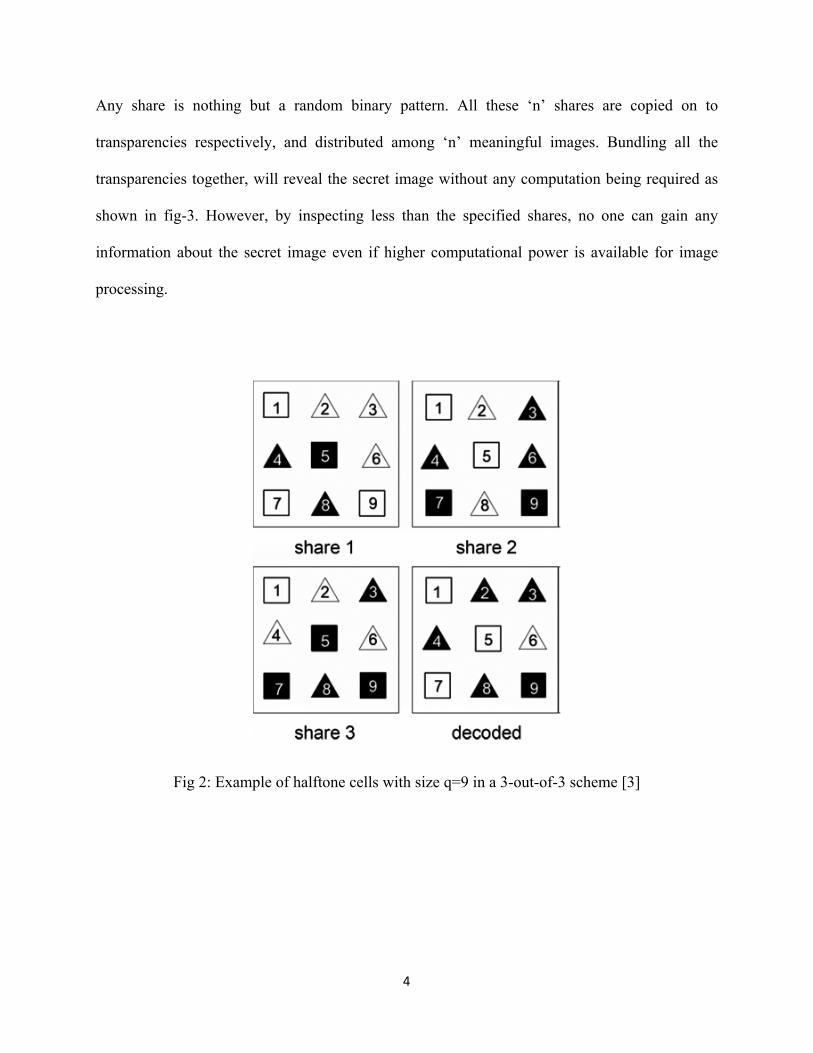
Any share is nothing but a random binary pattern. All these ‘n’ shares are copied on to
transparencies respectively, and distributed among ‘n’ meaningful images. Bundling all the
transparencies together, will reveal the secret image without any computation being required as
shown in fig-3. However, by inspecting less than the specified shares, no one can gain any
information about the secret image even if higher computational power is available for image
processing.
Fig 2: Example of halftone cells with size q=9 in a 3-out-of-3 scheme [3]
Page 12
5
Fig 3: Random pattern of encoded image with two shares. Resulted image is decoded image by
the overlaying of generated transparencies [17]
1.3 Sharing Multiple Secrets Using Visual Cryptography
To generate perfect ciphers or secret images Visual Cryptography is used. An image can be
divided into multiple shares, and that multiple shares can be stacked again to get original image.
Using VC the encrypted messages can be decrypted directly by the human visual system.
Without computation VC can generate the original image and this is a distinguishing quality of
the VC. The previous works on visual cryptography assume that the image or message is a
collection of black and white pixels where in each pixel is handled individually. The encryption
technique evaluates using ‘k’ shares out of ‘n’ secret shares. For a given image or message, ‘n’
transparencies are generated. If any ‘k’ of them is stacked together then the original image
(message) is visible. The image will not appear or be made visible to end-user if less than ‘k’
transparencies are stacked. Visual cryptography shares binary images only. Research works
introduced halftone and color halftone mechanisms in visual cryptography in order to share color
and grayscale images. Rather than considering only one secret, it will focus on how to share
multiple secrets using visual cryptography. This mechanism will merge two secrets into shares
using the master key, and then combine the two shares to form a new share ‘S1’. After that,
Page 13
6
master key is modified to generate a key share ‘S2’. The new share ‘S1’ and the key share ‘S2’
are employed to recover the secrets by shifting the key share ‘S2’ to various positions on ‘S1’.
For sharing individually, this mechanism has one key and two secrets. With the same master key
the secrets are encrypted and placed one after another. When the key is used on the secret the
first secret is made visible to user. The same is true for the second secret. In order to open the
next secret, the key has to be shifted by the images width or height. All secrets can be revealed
using the same key. The joint sharing scheme works in a similar way of the above process.
Shares are generated using the master key. All shares are read row by row and merged as single
image by writing these read rows from the encrypted shares. When the key share is used on the
merged image, the first secret share is revealed to end user, when the key is shifted down, the
second secret is revealed.
1.4 An Extended Visual Cryptography Algorithm for General Access Structures
This paper proposes a two-phased encryption algorithm of (ҐQual, ҐForb), EVCS for GASs. In the
solution procedures first phase, it generates intermediate shares of (ҐQual, ҐForb) VCS. These
intermediate shares have no appropriate appearance and no pixel expansion. In the second phase,
cover images I1, I2 will be added in these I-shares to yield the resultant shares of (ҐQual, ҐForb) as
shown in fig-4. In phase-II, the stamper will stamp the shares on images I1, I2. The Secret image
is encrypted in Phase-I as in fig-4 started from GAS Solver by taking secret image it encrypts the
image and forward to share synthesizer and this synthesizer will encrypt the images into shares.
These shares are embedded into the images I1, I2 by the stamper.
Page 14
7
The solution provided with the following structure
Fig 4: Solution procedures for EVCS.
Fig 4: Solution procedures for EVCS.
GAS Solver
Encryptor
Share Synthesizer
……………………………..
……………………………..
Stamper
I1
I2
I2………………….
I1…………………
Secret Image
Phase I
Phase II
Page 15
8
1.5 Embedded Extended Visual Cryptography Schemes
Embedded Extended Visual Cryptography EVCS can also be treated as a technique of
steganography. To avoid custom inspections on the encrypted images or shares EVCS is used,
because the shares of EVCS are not just shares but meaningful images, hence there are fewer
chances for the shares to be suspected and detected.
Proposed tool for Embedded Halftoned shares provides a user-friendly environment to
work with images. This application supports .gif and .png (portable network graphics) formatted
images and this application has been developed using swing and applet technologies, hence
provides a friendly environment to users.
Problem Definition: Whenever user transmits the data (image) in the network, any
unauthenticated person can read data (image). In order to provide security to data (image)
generally sender will encrypt the data (image) and send it the intended person and the receiver
will decrypt the encrypted data (image) and uses it.
2. Objective
The aim of this project would be to hide the knowledge in the data where sender and
recipient only knew the real one. The aim of this project is achieved using Halftone algorithm for
data hiding an image with in an image. Hence, the sender and recipients can have a tool to
encrypt and decrypt the transformed images, as provided.
Page 16
9
3. Implementation of EVCS mechanism
3.1 Halftone technique using dither matrix
The drawback of the VCS is, it cannot deal with the gray-scale image. VCS to deal with the
gray-scale images was originally proposed by MacPherson. It has large pixel expansion like c x
m. ‘c’ is the number of the gray-levels and ‘m’ is the pixel expansion of the corresponding black
and white pixels. To deal with the gray-scale image, the halftoning technique was introduced into
the visual cryptography. This technique is used to convert the gray-scale image into the binary
image. In printing applications, this technique has been extensively used which has been proved
efficient. VCS technique can be applied directly to the binary images. But in this process the
concomitant loss in quality of image is unavoidable. This paper will make use of the patterning
dithering. The patterning dithering makes use of a certain percentage of black and white pixels,
often called patterns, to achieve a sense of gray scale in the overall point of view. The pattern
consists of black and white pixels, where different percentages of the black pixels stand for the
different grayness’s. The halftoning process is used to map the grayscale pixels from the original
image into the patterns with certain percentage of black pixels. The halftoned image is a binary
image. However, in order to store the binary images one needs a large amount of memory. A
more efficient way is by using the dithering matrix. The dithering matrix is a c x d integer
matrix. The entries, denoted as Di,j for 0 ≤ I ≤ c-1 and 0 ≤ j ≤d-1.of the dithering matrix are
integers between 0 and cd-1 which stand for the gray-levels in the dithering matrix. Denote gє
{0, …. , cd} as the gray levels of a pixel in the original image.
Page 17
10
3.2 Halftoning process for each pixel i
Input: The c x d dithering matrix D and a pixel with gray-level g in input image I.
Process:[1]
For i=0 to c-1 do
If g<=Dij then print a black pixel at position (i,j);
else print a white pixel at position (i,j);
Output: The halftoned pattern at the position of the pixel
D0 Matrix [1] is expected Dither Matrix with 10 gray levels for 1st transparency.
D0=
Fig 5: Traditional Halftone Transparencies a) 1st transparency b) 2nd transparency c) Recovered
image from transparency
7 0 5
2 4 6
3 8 1
Page 18
11
Using c x d dither matrix, user will generate halftoned transparencies by computing secret image.
By comparing the value at each pixel with the threshold value of the dither matrix from pixel
(0,0) position to complete image. Program will form color on the selected pixel. That color may
be white or black depending upon the pixel value. After generating the transparency, the
transparency looks like figures 5.a and 5.b.
3.3 Embedding Shares
The idea of our embedded EVCS contains two main steps:
1) Generate ‘n’ covering shares.
2) By embedding the corresponding VCS into the ‘n’ covering shares generation of the
embedded shares.
1) Generate the covering shares for an access structure take gray-scale original share images, and
output ‘n’ binary meaningful shares. The stacking results of the qualified shares are all black
images. The information of the original share images are all covered images. The advantage of
covering shares is that, when the qualified subsets are stacked, all the information of the patterns
in the original share images is covered. So the visual quality of the recovered secret image is not
affected. Otherwise, in secret image, the information of the original share images may appear, so
might results in bad visual quality.
2) First make use of the corresponding VCS to encode a secret image, and then embed the shares
of the corresponding VCS into the covering shares that were generated in step 1. The output
shares of step 2 are the embedded shares. In this way, when stacking a qualified subset of
embedded shares, decryption to transparencies will result in the secret image, because the
Page 19
12
stacking result of decrypted covering shares covers all the information of the original share
images.
3) Decrypt the embedded share and stack them again using application to get original image.
3.4 The embedding process [1]:
Input: The ‘n’ covering shares constructed as the corresponding VCS (C0, C1) with pixel
expansion and the secret image ‘I’ is as in fig-6.
1. Dividing the covering shares into blocks that contain t(≥m)sub pixels each.
2. Choose ‘m’ embedding positions in each block in the ‘n’ covering shares.
3. For each black (respectively, white) pixel in I, randomly choose a share matrix M є C1
(respectively, M є C0).
4. Embed the ‘m’ sub pixels of each row of the sharematrix M into the ‘m’ embedding positions
chosen in step 2.
Output: The ‘n’ embedded shares e0, e1, ..en-1 as in fig-6.
As in figure-6, the image is encrypted in to ‘n’ number of transparencies. Each transparency is
embedded into e0, e1, ..en-1 Embedding images. These embedding images will be separated and
decrypted to original by the tool.
Page 20
13
Fig 6: Embedding Algorithm Presentation
4. System Design
4.1 System and Software Used in this project
This project was implemented on a personal computer.
The hardware and software involved are as follows.
• Intel Pentium IV 2.2GHz
• Windows XP Service Pack II
• JDK v1.6
• Netbeans v6.8
Page 21
14
4.2 System Requirement
Processor should contain 2.2 GHz speed for better performance and System required 40GB hard
disk space for the Software and Operating System and 128MB free RAM space for the
application; however RAM space varies because of the image operations and image size.
4.3 User Interface Design
4.3.1 Main Window
It is written in java swings. It is to open the operational window or frames to perform set of
operations on images using the specified techniques. It consists of basic window operations like
closing and minimizing but restoring or rescaling is not possible.
4.3.2 Visual Cryptography Window
This is written in Applet as well as Swing framework. In this, user consists of various
Visual Cryptography options. User can perform Loading Image, Loading Transparencies, Saving
Transparencies, Visualizing transparencies to original images, and Individual transparency
visualization.
This window consists of all kinds of operations related to image processing, which are required
for visual cryptography proposed in the algorithms.
Page 22
15
4.3.3 Embedding Window
It is purely written in java swings. In this window we can encrypt and embed saved
transparencies to the meaningful shares (images). And again, we can regain them by simply
making the decryption process for the specified location with the specified filename. Results of
each operation can appear simultaneously on the window result area.
4.4 Software Engineering Techniques
4.4.1 Requirements
4.4.1.1 Software Tools
Integrated Development Environment tool like Netbeans IDE is used in this project. Because of
this tool project construction of user interface becomes easier and we can represent interface in
Rich Graphical representation. It gives feasibility for the inbuilt classpath and path settings and
resource links. We can view the interface design without running the code. And modifications
can be done within no time by using this tool.
4.4.1.2 Functional and Non-Functional Requirements
The ‘functional requirements’ of the project are as follows:
1. Main window is used for navigation purpose in the application window. Using this, we can
perform individual operations like visual cryptography and also embedding images in separate
manner or individually.
2. Visual Cryptography window is used to perform cryptography operation on images or
steganography operations. We can transform images into transparencies and we can save all the
Page 23
16
transparencies. After embedding and decrypting the images we can combine transparencies to
get original image.
3. Embedding window is used to perform the embedding operations on transparencies. The
transparencies can be encrypted and embedded. By this tool we can separate the embedded
images into original share and transparencies. And saving the transparency at specified location
and with specified filename.
Among many ‘non-functional requirements’, the project must be very user-friendly. People will
likely use such software tools with just a little more knowledge in using computers other than for
everyday tasks.
4.4.1.3 Structured Requirements
The project is to provide user-friendly operational tool for the embedded extended visual
cryptography. This should allow user to operate easily on images for the EVCS operations
1. Give Self-explanative user interface.
2. On clicking encrypt/decrypt button visual cryptography window should appear.
3. User allowed closing visual cryptography window individually.
4. On clicking embedding window button-embedding window should appear.
5. User allowed closing embedding window individually.
6. When user closes the main window all operational windows are stop the actions and
closed.
Page 24
17
Visual Cryptography window
1. User can load the images for the transparencies generation.
2. After generation transparency user can visualize the resulted transparency images
individually or after grouping them.
3. User is allowed to save all the transparencies in the hard disk.
4. After saving the entire transparencies, user can embed them with meaningful images
using embedding window.
Embedding Window
1. User is allowed to load specified transparency during the embedding process with real or
meaningful image.
2. User can specify the image location where image name is same as the meaningful image
name. The format of the image is PNG so that it will be easy to transfer in any network.
3. With this tool, user can separate the meaningful image and transparency by providing
location and filename.
4. After separating all transparencies, user has the visual cryptography tool for transparency
visualization.
4.5 Analysis
The requirement of this project is to compute the images into halftoned images and embed these
transparencies into meaningful images and share them on network. By the proposed system code,
this requirement is fulfilled by the gray-scaled image conversion into halftoned image
Page 25
18
transparencies, and these transparencies can be embedded with real images. After embedding,
they are automatically stored in portable network format for the sharing purpose on network.
Hence, the input is a gray scale for the visual cryptography window and gives out halftoned
transparencies. Embedding window has the inputs as halftoned transparencies and real share
image is considered for embedding. The output of this window is in encrypted embedded image.
Embedding window can be used for the decryption and separation of real share image and
transparency.
4.6 Design
System design consist of various operations and user operational flows as follows
1. Halftone Image Generation Process
Fig 7: Flow diagram of Halftone transparency generation
Image-‐1
Interface
Source Image
Halftoned Images
Image Processing
Save transparences
Page 26
19
Fig-7 explains the process of halftoned transparency generation. Select a gray level image using
user interface, then application will take care about the image processing and generates halftoned
transparencies. Save all those transparencies for further processing.
2. Embedding Process of Transparencies
Fig 8: Flow diagram of Halftone transparency embedding in original share images
As in Fig-8 from user interface select transparency, next select original image then specify the
location in local system where to store the embedding image. After generating embed image that
image automatically named with embedding image name with png extension.
Select Transparency
Interface
Select Real Share Image
Specify Destination location
Embed Image
Page 27
20
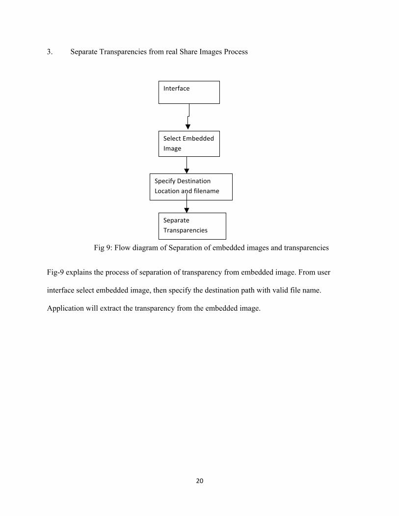
3. Separate Transparencies from real Share Images Process
Fig 9: Flow diagram of Separation of embedded images and transparencies
Fig-9 explains the process of separation of transparency from embedded image. From user
interface select embedded image, then specify the destination path with valid file name.
Application will extract the transparency from the embedded image.
Select Embedded Image
Interface
Specify Destination Location and filename
Separate Transparencies
Page 28
21
4. Decryption of Halftoned Transparencies
Fig 10: Flow diagram of Halftone transparency selection and Viewing Knowledge
Interface
Halftoned Transparency
Source Image
Image Processing
View Knowledge
Transperency-‐1 ……… Transparency-‐n
Page 29
22
As shown in fig-10 user has to select all transparencies, which are extracted from embedded
images into the application. Application will store all the transparencies in local variables and
stacks them one on another to generate the secret image.
Use Case Diagrams:
1. Users and System
Fig 11: Usecase diagram of User and System
User can access the System with Main Window. All Visual Cryptography Operations can be
performed using Visual Cryptography Window, and Embedding Operations can be performed
using Embedding Window the user access the system operations through the user interface.
Page 30
23
2. User Operations
Fig 12: Sequence Diagram of User and User Interface operations
User runs the project then the main window opens; user can open either Visual Cryptography
operations window or embedding operations window to perform cryptography operations.
Page 31
24
3. Halftone Process
Fig 13: Halftone transparencies generation sequence diagram
User runs Visual Cryptography window and to generate transparencies user has to load grayscale
image into system and select the number of transparencies then encrypt the gray scale image into
number of selected halftoned images and save all generated transparencies.
Page 32
25
4. Embed Process
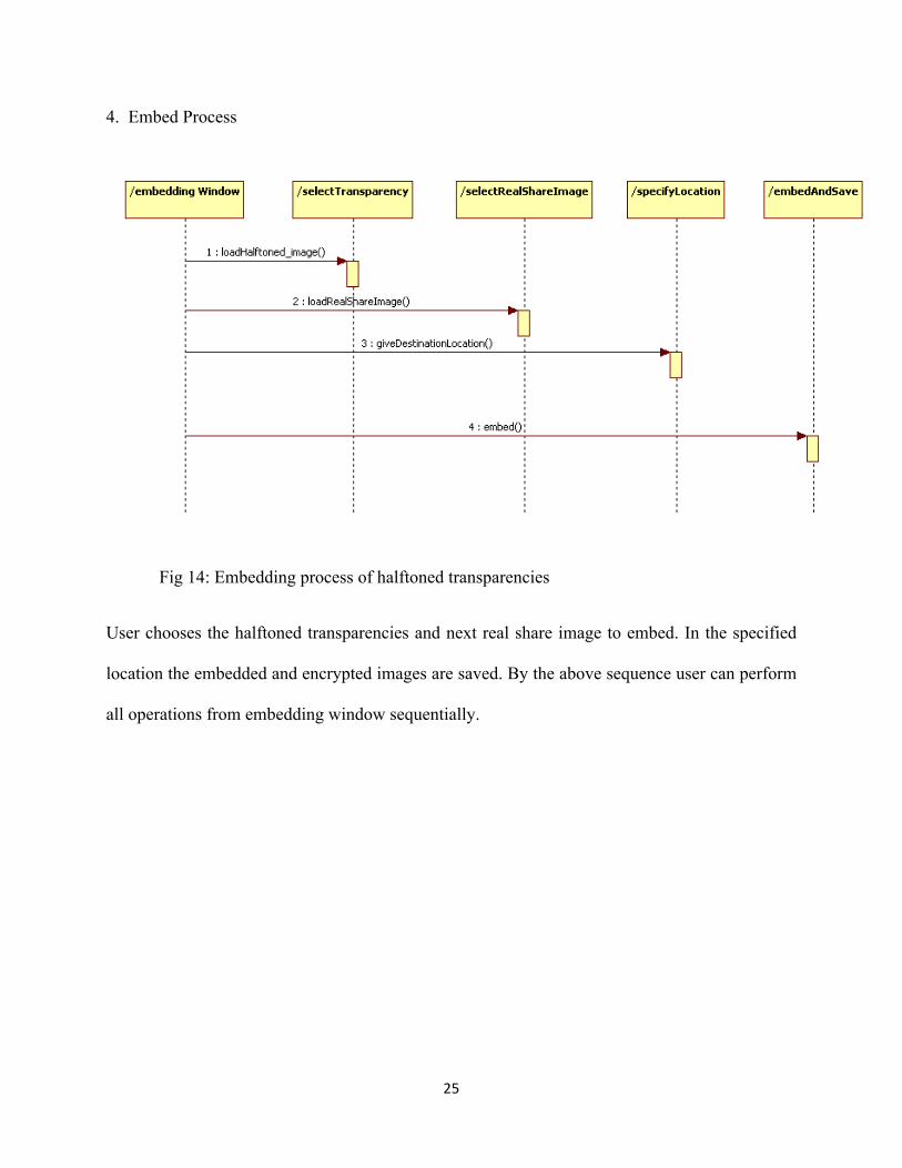
Fig 14: Embedding process of halftoned transparencies
User chooses the halftoned transparencies and next real share image to embed. In the specified
location the embedded and encrypted images are saved. By the above sequence user can perform
all operations from embedding window sequentially.
Page 33
26
5. Separation of Transparency from Real Image
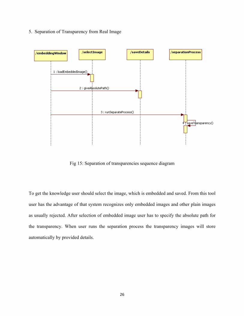
Fig 15: Separation of transparencies sequence diagram
To get the knowledge user should select the image, which is embedded and saved. From this tool
user has the advantage of that system recognizes only embedded images and other plain images
as usually rejected. After selection of embedded image user has to specify the absolute path for
the transparency. When user runs the separation process the transparency images will store
automatically by provided details.
Page 34
27
6. Visualization of Knowledge
Fig 16: Visualization process sequence diagram
User loads all transparencies using Visual Cryptography window. User has the feasibility that
system recognizes how many transparencies present for this specified image after loading 1st
transparency itself. Open window dialog box appears until all transparencies loading completed.
After loading all transparencies automatically all halftoned transparencies decrypted and user can
visualize the original image or knowledge.
Page 35
28
7. Components of System
Fig 17: Component Diagram of System components
Proposed System consists of three major components MainWindow,
VisualCryptographyWindow and EmbeddingWindow. Visual Cryptography component can
individually run and reuse as the subsystem for external usage and it applies also for embedding
window component. Hence these two are dependent on main window to run and associated with
the main window for user operations.
Page 36
29
5. Results and Testing
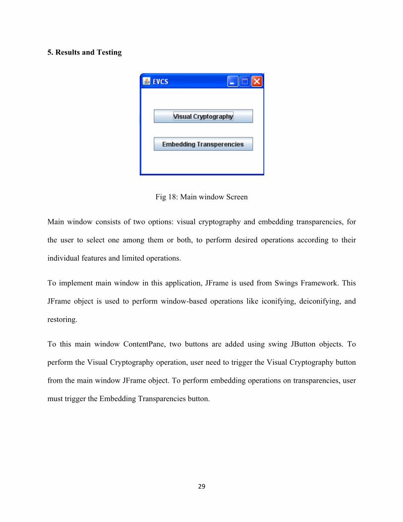
Fig 18: Main window Screen
Main window consists of two options: visual cryptography and embedding transparencies, for
the user to select one among them or both, to perform desired operations according to their
individual features and limited operations.
To implement main window in this application, JFrame is used from Swings Framework. This
JFrame object is used to perform window-based operations like iconifying, deiconifying, and
restoring.
To this main window ContentPane, two buttons are added using swing JButton objects. To
perform the Visual Cryptography operation, user need to trigger the Visual Cryptography button
from the main window JFrame object. To perform embedding operations on transparencies, user
must trigger the Embedding Transparencies button.
Page 37
30
Fig 19: Visual Cryptography window [20]
This is the visual cryptography window, to perform image cryptography operations to generate
halftoned images. This application is developed using the swing framework and applet
framework.
Page 38
31
This application consists of JMenu, JMenuItem, JButton, JPanel, JFrame and Image resources as
a part of User-Friendly Interface for the end user.
Fig 20: Loading Gray scaled image
Page 39
32
Select Gray scale PNG or GIF image into the system for generation of transparencies. After
selecting, the image is rendered into 100x100 pixel panel to fit and display in the Applet
framework system.
File Menu consists of Load Image JMenuItem to open JFileChooser object to choose the
appropriate image from the hard disk. Using JFileChooser_Object.show() the File chooser
window will open, to make the user, choose an image.
Fig 21: Mode of operation to select number of transparencies
Page 40
33
After selecting image, it will be displayed in 100 x 100 pixel ratio. This is achieved using the
ImageIO class read(file) method in java. This read(file) returns BufferedImage Object. And
“ImageIO.read(f).getScaledInstance(WIDTH,HEIGHT,Image.SCALE_SMOOTH)” code to
result the buffered image.
Mode menu is used to select the number of transparencies and also user has a choice of using
number of transparencies, to reveal the original image. Menu ‘Basic 2 out of n’ consists of 2 out
of 2, 2 out of 3 and 2 out of 4 menu items. And ‘Basic 3 out of n’ consists of 3 out of 3. In this,
the first digit specifies the minimum transparencies required for generating the original image
and the second digit specifies the number of transparencies user want to generate.
After selecting k out on n shares, the value of n and k will get stored in ‘number of
transparencies’ and ‘min_number of shares’ variable respectively.
Page 41
34
Fig 22: Generating operation of halftone images
By selecting Visual Cryptography Menu item, encrypted transparencies are generated. Specified
number of transparencies are generated and stored in primary memory as Buffered images.
Page 42
35
As specified above, in this process it uses k and n value to generate dither matrix. This dither
matrix will be generated using following IntMatrix class. In IntMatrix class, user can set the
color of pixel as black and white programmatically using threshold value.
SetElement(int[][]) method in IntMatrix class take the values as position x, y and color of pixel
either WHITEPIXEL or BLACKPIXEL. This function will generate dither matrices according to
the width and height of the secret image. These dither matrices are further used to generate the
halftoned transparencies using Encryptor class. The encryptor class will encrypt the image for 8,
16 and 24 bit images. With left shift operator (<<), for WHITEPIXEL the code will be like
“WHITEPIXEL = (255 << 24) | (255 << 16) | (255 << 8) | 255” and same for BLACKPIXEL.
Using Permutation class the encryption process will be done. Encryptor uses the Permutation
class object as shown below
Up to max permutation of an image the below two statements will repeated.
m_Cwhite[i] = (IntMatrix)c0.get(i)// for white pixel
m_Cblack[i] = (IntMatrix)c1.get(i)//for black pixel
Page 43
36
Fig 23: Save all transparencies screen
After generation of encrypted transparencies, user can save all transparencies by choosing save
all transparencies JMenuItem from file menu.
Page 44
37
By triggering this menu item, JFileChooser object gets visible to make the user to save the
transparencies. JFileChooser window will appear up to n time, where n is the total number of
transparencies.
Fig 24: Location selection of transparencies to save
Page 45
38
User can save the transparencies as images in gif or png format at the specified location in
secondary memory device or hard disk. These transparencies will be stored in the format of gif
or png. FileFilter is added to JFileChooser object to restrict the user, to give extensions as
program specific.
Fig 25: Embedding window for embed operations
User has the privileges like selecting transparency, selecting original share, providing location to
store embedded image. If a specific location is not provided, the default location it takes is C:
drive.
Page 46
39
User can separate the embedded images from this window itself. So user can embed and separate
the images from the same window.
This window is developed using JFrame of swing framework using java. The components added
to this window are JTextField to retrieve destination addresses, which is used to save embedded
image, and separated transparency. JTextArea is to display the content of the operation. JButton
is used to create the buttons for the purpose of Selecting Transparency, Selecting original image,
and to perform Embedding operation. JButton is used to create the components, which triggers
separation and selection of embedded image. Here, JFileChooser is used to select the
transparencies, original image and Embedded image. The File chooser contains File filter option
for png and gif file.
Page 47
40
Fig 26: Select transparency from saved location
User can select the stored transparency from hard disk. As image is stored in PNG format by
default, transparency can be selected from embedding window as PNG file. The file chooser
window has file filter option as PNG.
As it contains file filter option as PNG, user can only view PNG file extension files in file
chooser window.
Page 48
41
Fig 27: Select the original share image
User can choose original share image by selecting “Select Original Share” button. Image
selection is of any interest accordingly, but to transfer image on to network, only png or gif are
preferable formats. The selected transparency is stored in image file called “transpFile”. This is
image type variable, which stores the selected or opened image using JFileChooser object.
Page 49
42
Fig 28: Real share image selection window
User has to select the Real Share image or Original Share image, which has more pixel ratio than
the transparency. Otherwise the ‘original image selection’ window will appear again to select the
valid original share image. This selected original image is stored in ‘shareFile’ image variable.
Page 50
43
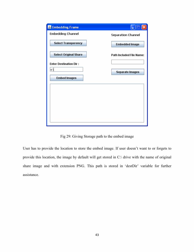
Fig 29: Giving Storage path to the embed image
User has to provide the location to store the embed image. If user doesn’t want to or forgets to
provide this location, the image by default will get stored in C:\ drive with the name of original
share image and with extension PNG. This path is stored in ‘destDir’ variable for further
assistance.
Page 51
44
Fig 30: Embedding operation result
When embed image is triggered by clicking ‘Embed Images’ button the following operations are
performed:
The selected files are stored in local variables and those file’s path will be read and stored in
temporary variables for computation purpose like ‘temp1’ for transparency image, ‘temp2’ for
original image, ‘temp3’ for resulting embedded image.
FileHider class is used for embedding and separation operations. ‘fh’ is an FileHider object
which is used to call hideInImage(file,image) method.
Page 52
45
hideInImage(file,image) method is used to embed the transparency in the original image which
internally uses ‘ImageConverter’ class. This class converts an image in to byte array by calling
method in getBytes(image). The following code is used to transform the image into bytes.
int[] bytes = new int[image.getWidth() * image.getHeight() * 3 + 2];
alpha = new int[image.getWidth() * image.getHeight()];
for (int i = 0, k = 0, l = 0; i < image.getWidth(); i++) {
for (int j = 0; j < image.getHeight(); j++, k += 3, l++) {
rgb = image.getRGB(i, j);
bytes[k] = (rgb >> 16) & 0xFF;
bytes[k + 1] = (rgb >> 8) & 0xFF;
bytes[k + 2] = (rgb >> 0) & 0xFF;
alpha[l] = (rgb >> 24) & 0xff;
}
}
For computational purpose, few values are required to embed image like alpha values, rgb values
from image. These values can be obtained by calling getRGB(positionX,positionY). These
positionX and positionY are pixel positions of the image. Here rightshift operator is used to
transform pixel values. Image bytes are taken according to its width and height. Also, alpha array
size is taken as equal to the image size, so it can extract the original image size.
Page 53
46
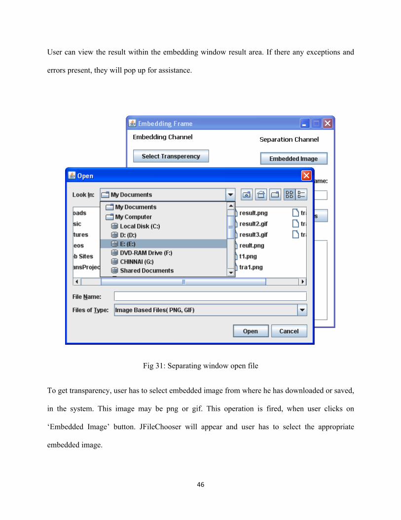
User can view the result within the embedding window result area. If there any exceptions and
errors present, they will pop up for assistance.
Fig 31: Separating window open file
To get transparency, user has to select embedded image from where he has downloaded or saved,
in the system. This image may be png or gif. This operation is fired, when user clicks on
‘Embedded Image’ button. JFileChooser will appear and user has to select the appropriate
embedded image.
Page 54
47
Fig 32: Giving absolute path
User has to provide the absolute path in the given text field. If user forgets or doesn’t give
information about the separated transparency saving, it will give error message.
The separation process will take place using following operations.
Selected embedded image is first stored in local variable ‘image’. Then this local variable is
passed to FileHider class to extract the transparency from the image.
This image is then computed with ImageConverter class to extract the byte array using getBytes
(image) method.
Page 55
48
Using BitManipulator class, the transparency will be extracted by using method
getInformation(bytes[]) method.
for (int j = 0; j < 8 && i < bytes.length; j++, i++) {
cur |= (bytes[i] & 1) << 7 - j;
}
Here i is the byte array length, where the manipulated byte values will store at local bytes array
variable for further assistance.
After this operation ImageConverter class object is used to call the getImage(bytes). Here bytes
is an integer array. The conversion operation is as follows
Image.setRGB(i, j, new Color(bytes[k], bytes[k + 1], bytes[k + 2], alpha[l]).getRGB());
Above statement is the key to reform the transparency from the original image.
Page 56
49
Fig 33: Result of the separated transparency.
After giving the absolute path information, user performs separate image operations. The
separated image is a transparency and it is stored as png or gif as our system supports both png
and gif formats. String builder is used to appear the resulted image in the result area window. In
StringBuilder class append(string) method is used to append the text to the result window. Here
separation of transparency and original image is done using BitManipulator class, FileHider class
and ImageConverter class. ImageConverter class gets the embedded image in the form of bytes.
And FileHider invoke the BitManipulator class method “getInformation(img)” in the
extract(img) method of current class.
Page 57
50
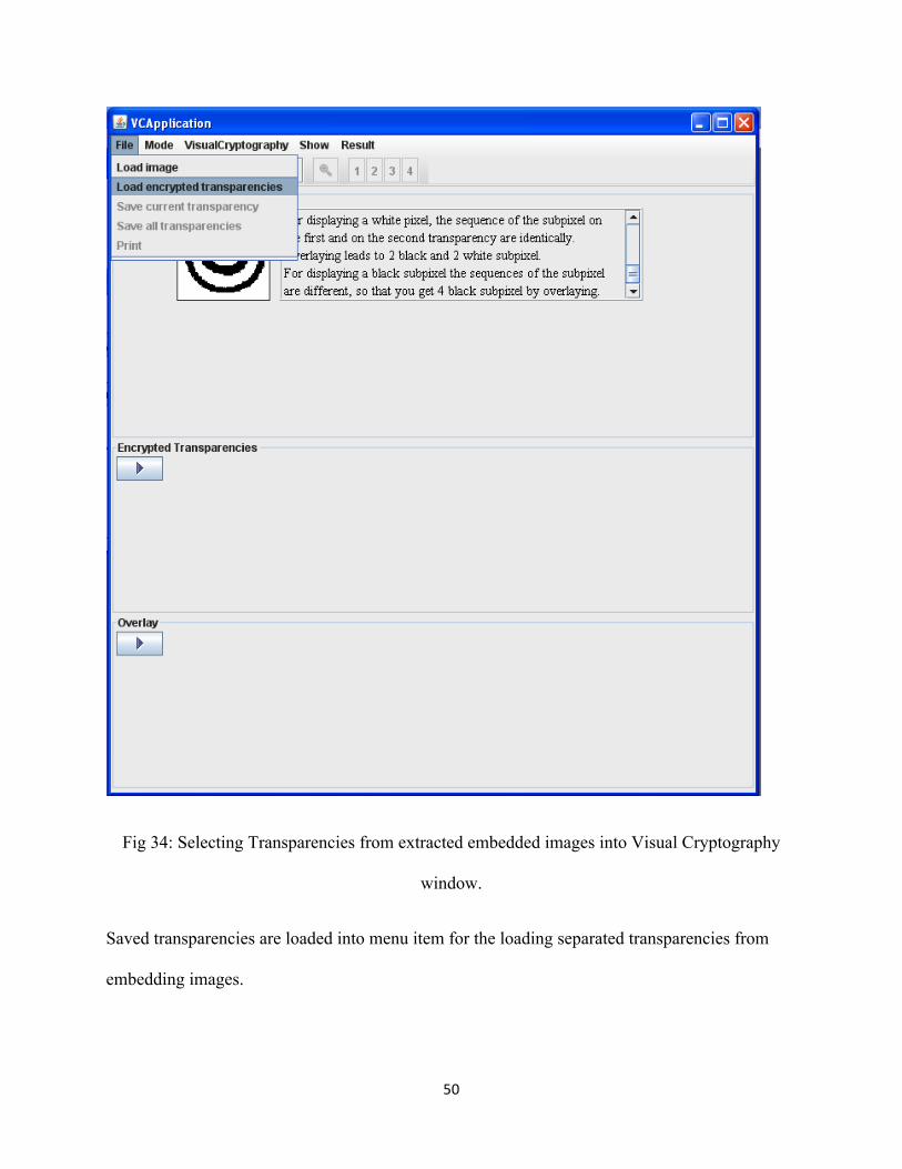
Fig 34: Selecting Transparencies from extracted embedded images into Visual Cryptography
window.
Saved transparencies are loaded into menu item for the loading separated transparencies from
embedding images.
Page 58
51
Fig 35: Selecting saved transparency
After selecting 1st Transparency the system automatically recognizes number of transparencies
existed, to decode the original knowledge. The open dialog box will appear, according to the
number transparencies requiredto produce the knowledge image.
Page 59
52
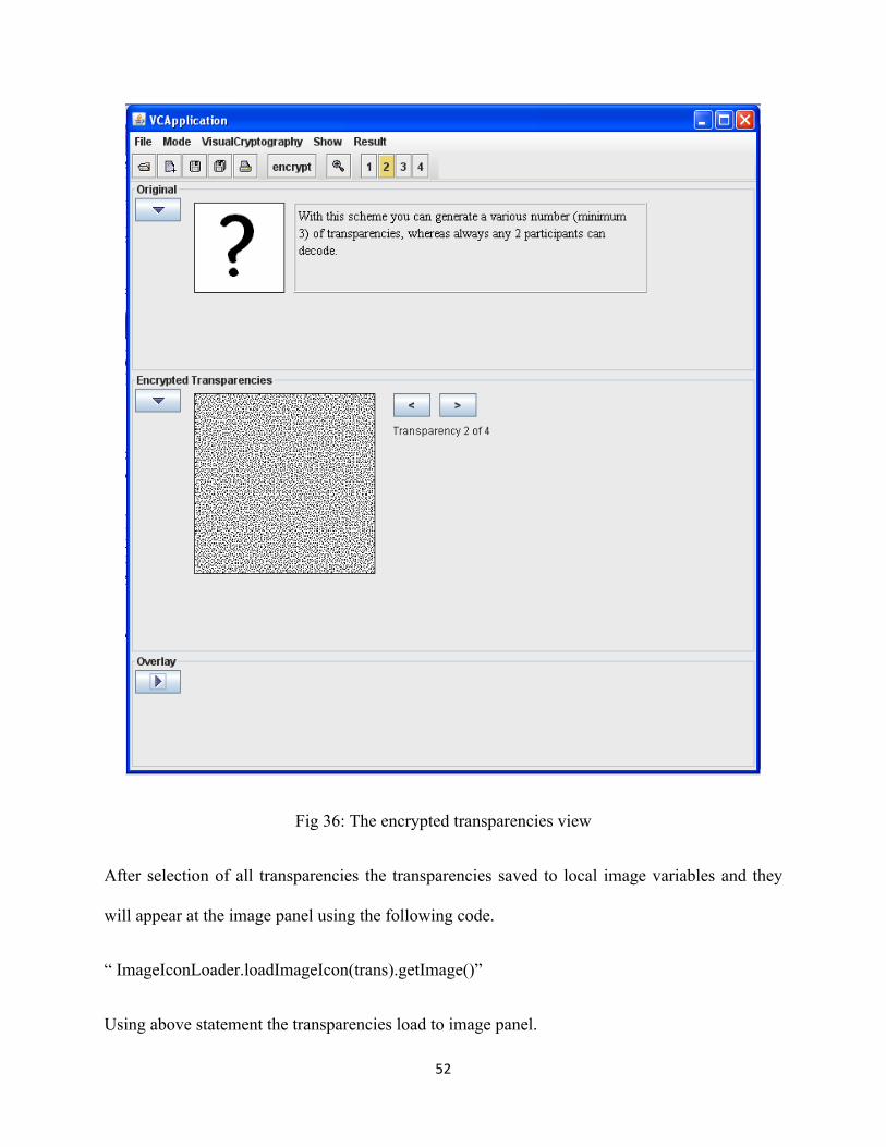
Fig 36: The encrypted transparencies view
After selection of all transparencies the transparencies saved to local image variables and they
will appear at the image panel using the following code.
“ ImageIconLoader.loadImageIcon(trans).getImage()”
Using above statement the transparencies load to image panel.
Page 60
53
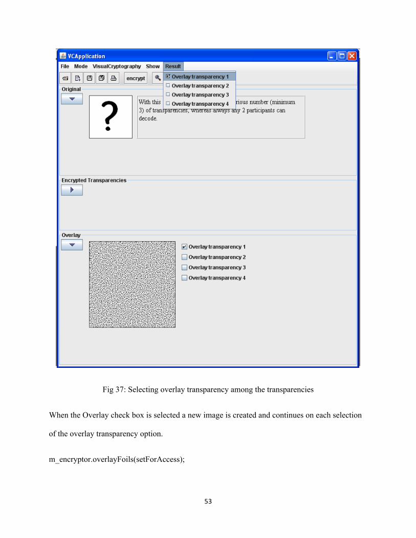
Fig 37: Selecting overlay transparency among the transparencies
When the Overlay check box is selected a new image is created and continues on each selection
of the overlay transparency option.
m_encryptor.overlayFoils(setForAccess);
Page 61
54
Image img = m_applet.createImage(m_encryptor.getImageProducerOverlay());
m_ovlImagePanel.setImage(img, m_encryptor.getWidthEnc() ,m_encryptor.getHeightEnc());
Final Result:
Fig 38: Visualizing the complete knowledge by selecting all overlay transparencies
Page 62
55
After selection of all overlay transparencies or k number of transparencies out of n, the secret
image will appear. Stacking all overlay transparencies, generates this image and set to the
resultPanel object type of Panel class from AWT.
m_applet.resultPanel.validate();
m_applet.resultPanel.setVisible(true);
This result is from overlaying the transparencies or stacking the transparencies one over the other
without any computations other than storing and framing on image panel.
Types of testing performed in this project
The following testing methods have been performed in the proposed project and were
successful:
1. Unit testing
2. Integration testing
3. Validation testing
4. Output testing
Unit Testing:
Individual components and their functionality are tested.
i. Visual Cryptography component is tested by generating transparencies and
verifying whether it is providing the shares according to the required output.
Page 63
56
ii. Embedding component is tested individually by using saved transparencies
embedding into proper original images. The embed process is completed if we
doesn’t encounter any noise or loss of data in the embedding image.
Integration Testing
After integrating the individual components, Visual Cryptography component and
Embedding component with the main component the coordination of individual
components are according to the required output.
Validation Testing
At the required positions validations are performed.
1. While loading the transparency, validation is performed to find whether the
loaded transparency is valid or not.
2. While giving destination directory for the separated transparency to store at the
local drive, validation is performed whether valid destination path is given or not.
Output Testing
After loading the separated transparencies into the visual cryptography component, the
original secret image is tested for accuracy.
Test cases
The proposed project was tested for all the test cases sequentially. The following test
cases were tested:
• Verifying Encrypted Transparencies for k out of n shares
Page 64
57
Selecting less than k shares.
Selecting k number of shares.
Selecting n number of shares.
• Validating Transparency loading
For successful loading of transparencies
For unsuccessful loading of transparencies
• Verifying the secret image halftone shares generation
• For colored image
• For gray level image
• Verifying the embed process of natural images and secret share.
• Embedding in valid image
• Embedding in invalid image
• Validation of Absolute Path for Transparency Saving
Page 65
58
Verifying Encrypted Transparencies for k out of n shares
Transparency generation
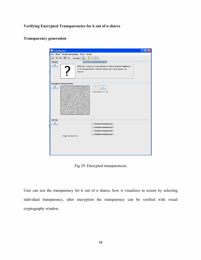
Fig 39: Encrypted transparencies
User can test the transparency for k out of n shares, how it visualizes in screen by selecting
individual transparency, after encryption the transparency can be verified with visual
cryptography window.
Page 66
59
Less than k transparency selection
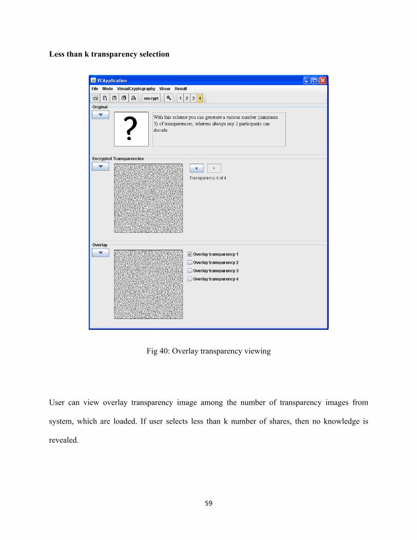
Fig 40: Overlay transparency viewing
User can view overlay transparency image among the number of transparency images from
system, which are loaded. If user selects less than k number of shares, then no knowledge is
revealed.
Page 67
60
Exactly k shares selected
Fig 41: Selection of more than one transparency (Exactly k shares)
After selection of k shares user has a view of knowledge image as appeared in Fig 41. When user
selects exactly k number of transparencies out of n number of transparencies, the secret image is
revealed to the end user.
Page 68
61
Selecting n number of or total shares
Fig 42: Complete overlay transparency images
After selection of complete overlay transparencies, the original image or knowledge will appear
as specified in Fig 42. If user, selects n number of total transparencies, the secret image appears
with good quality.
Page 69
62
Validating Transparency loading
For successful loading of transparencies
Fig 43: Selecting Valid Transparencies
One can load transparencies using the tool. These transparencies are then saved after they
have been generated from the secret image using halftone process.
Page 70
63
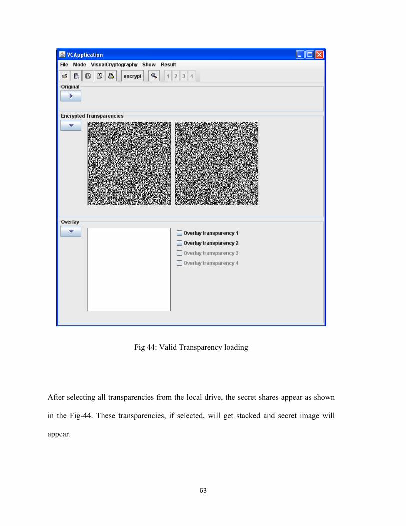
Fig 44: Valid Transparency loading
After selecting all transparencies from the local drive, the secret shares appear as shown
in the Fig-44. These transparencies, if selected, will get stacked and secret image will
appear.
Page 71
64
For unsuccessful loading of transparencies
Fig 45: Complete overlay transparency images
As shown in fig-45, a user tries to load an image, which is not a transparency.
Page 72
65
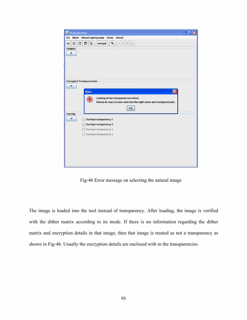
Fig-46 Error message on selecting the natural image
The image is loaded into the tool instead of transparency. After loading, the image is verified
with the dither matrix according to its mode. If there is no information regarding the dither
matrix and encryption details in that image, then that image is treated as not a transparency as
shown in Fig-46. Usually the encryption details are enclosed with in the transparencies.
Page 73
66
Verifying the secret image halftone shares generation
For colored image
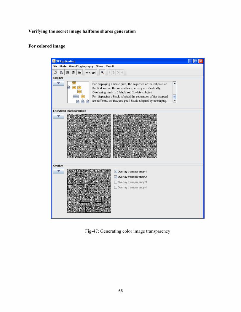
Fig-47: Generating color image transparency
Page 74
67
The proposed system is valid only for grayscale images, if the color images are selected to
produce transparencies, and those transparencies will appear as shown in Fig- 47. The image
losses its details and the colored image is transformed into gray level image.
For gray level image
Fig-48: Generating gray level image transparency
Page 75
68
If any gray image is selected to produce transparencies, the transparencies will appear as
specified in Fig- 48. The image won’t lose its information and also user gets low noised secret
image.
Verifying the embed process of natural images and secret share.
Embedding in a valid image
Fig-49: Successful transparency embedding in original image
Page 76
69
After embedding secret shares in the original images, the result will appear in the result
area. “Process completed search file in C:\” message is displayed after successful embed
operation as shown in fig-49. Where “c:\” is destination path, where the embedded image
is stored.
Embedding in an invalid image
Fig-50: Validation of Original image for embedding transparency
Page 77
70
While embedding, if user selects an invalid image like less resolution image, then the error
message will appear and shows the File chooser dialog box again to select proper file to embed.
This is a recursive process until a proper image file is selected or cancel button is clicked. The
error message that will be prompted is, “The file is too big, to save it into these 1 image(s) please
insert the path to a next one”.
Validation of Absolute Path for Transparency Saving
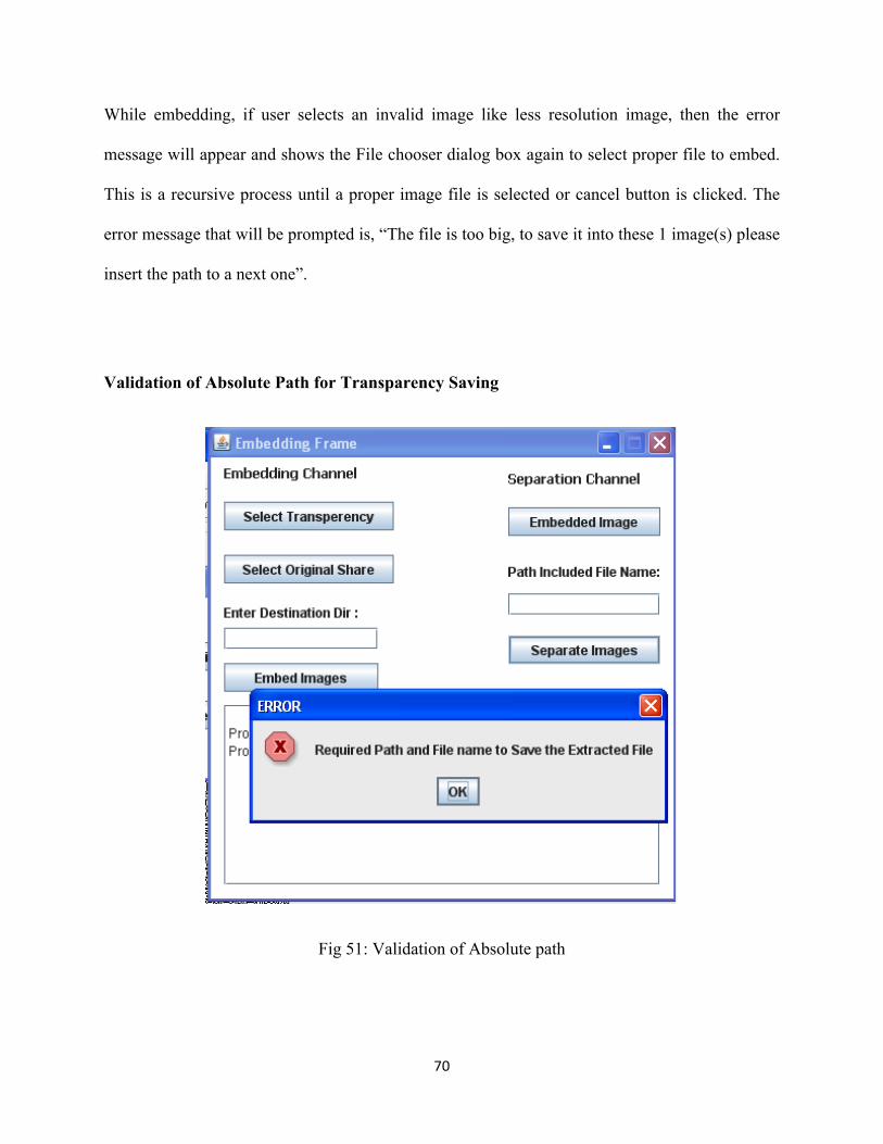
Fig 51: Validation of Absolute path
Page 78
71
If user forgets the absolute path section while splitting the embedded image into original share
and transparency, an error message will appear and it will display the JOptionPane dialog box.
6. Conclusion
The Visual Cryptography tool developed here is used to encrypt and decrypt the images. In this
project, generation of transparencies is achieved using Halftoning of images via a threshold
value. In this Halftoning algorithm, dither matrix is used as a static value. The halftoned secret
image shares are obtained by reading the secret image as a matrix. Each pixel of share is
compared with the threshold value. This generation process of transparencies is important,
because secret image is obtained by stacking these transparencies by the end-user. This complex
process is achieved using a user-friendly interface. So any user can operate this application even
without basic knowledge of cryptography. Even, it is same with the embedding process; any user
can embed the transparency by clicking few buttons.
This application will provide immediate visualization of secret image by stacking transparencies.
So user will be guided with how embedding transparency in another image is done, how to get
the separated shares and also how the secret image should appear or how it looks like.
Using this application user can generate transparencies of gray level images only. User can
embed only images, which are png, or gif files ay any level of operation.
Page 79
72
7. Future Work
Using Halftone via Dither matrix, the application will encrypt and decrypt a secret image and
embed them in meaningful images. The meaningful images can be shared on the network. But
the proposed tool is only applicable for gray-scale images. And the application can transform
png and gif file extensions only.
As a future enhancement, the application can be developed for the colored images and
supporting more image formats. This application contains various input pages (images) from
user. As a future work, the application can be enhanced by making these input parameters
automated and also by reducing the number of operations that the user has to perform.
Page 80
73
8. Bibliography
[1] L. Feng, W. Chuankun, “Embedded Extended Visual Cryptography Schemes,” IEEE
Transactions on Information Forensics and Security, June 2011.
[2] D. S. Wang, F. Yi, and X. B. Li, “On general construction for extended visual cryptography
schemes,” 2009.
[3] Z.M.Wang, G. R. Arce, and G. Di Crescenzo, “Halftone visual cryptography via error
diffusion,” IEEE Trans. Inf. Forensics Security, Sep. 2009.
[4] F. Liu, C. K. Wu, and X. J. Lin, “Color visual cryptography schemes,” IET Inf. Security,
2008.
[5] D. S. Tsai, T. Chenc, and G. Horng, “On generating meaningful shares in visual secret
sharing scheme,” 2008.
[6] S. J. Shyu, S. Y. Huang, Y. K. Lee,R. Z.Wang, andK.Chen, “Sharing multiple secrets in
visual cryptography,” 2007.
[7] Z.M.Wang, G. R. Arce, and G. Di Crescenzo, “Halftone visual cryptography via direct binary
search,” Sep. 2006.
[8] Z. M. Wang and G. R. Arce, “Halftone visual cryptography through error diffusion,” in IEEE
Int. Conf. Image Processing, 2006,
[9] T. H. Chen and D. S. Tsai, “Owner-customer right protection mechanism using a
watermarking scheme and a watermarking protocol,” 2006.
[10] D. Jin, W. Q. Yan, and M. S. Kankanhalli, “Progressive color visual cryptography,” 2005.
Page 81
74
[11] P. Tuyls, T. Kevenaar, G. J. Schrijen, T. Staring, and M. Van Dijk, “Security displays
enable secure communications,” 2004.
[12] C. C. Lin and W. H. Tsai, “Visual cryptography for gray-level images by dithering
techniques,” 2003.
[13] M. Nakajima and Y. Yamaguchi, “Extended Visual Cryptography For Natural Images,”
2002
[14] P. A. Eisen and D. R. Stinson, “Threshold Visual Cryptography Schemes With Specified
Whiteness Levels of Reconstructed Pixels,” 2002.
[15] C. Blundo, A. De Bonis, and A. De Santis, “Improved Schemes For Visual Cryptography,”
2001.
[16] S. Droste, “New Results on Visual Cryptography,” 1996.
[17] G. Ateniese, C. Blundo, A. De Santis, D. R. Stinson, “Visual cryptography for general
access structures,” 1996.
[18] G. J. Simmons, W. Jackson, and K. Martin, “The geometry of shared secret schemes,” 1991.
[19] J. O. Limb, “Design of dither waveforms for quantized visual signals,” 1969.
[20] Visual Cryptography Application originally developed by Johannes boble, university of
Regensburg. Source is from http://www-sec.uni-regensburg.de/vc. Source modified for the
purpose of application in plain java files.


![An Approach for Grey Scale Image in Visual Cryptography ... · visual cryptography via half toning [8]. This visual cryptography technique uses dots to stimulate contiguous tone imagery](https://static.documents.pub/doc/80x56/60228ce1debc865c13580072/an-approach-for-grey-scale-image-in-visual-cryptography-visual-cryptography.jpg)


