VISUAL REPRESENTATION IN INDUSTRIAL DESIGN REGISTRATION: A PROPOSED GUIDELINE FOR TURKEY BASED ON LEGAL TEXTS AND GUIDELINES FROM EIGHT DIFFERENT JURISDICTIONS, AND INTERVIEWS WITH TURKISH PATENT INSTITUTE EXAMINERS IRMAK YALÇINER SEPTEMBER 2012
Transcript
VISUAL REPRESENTATION IN INDUSTRIAL DESIGN REGISTRATION:
A PROPOSED GUIDELINE FOR TURKEY BASED ON LEGAL TEXTS AND
GUIDELINES FROM EIGHT DIFFERENT JURISDICTIONS, AND INTERVIEWS
WITH TURKISH PATENT INSTITUTE EXAMINERS
IRMAK YALÇINER
SEPTEMBER 2012
VISUAL REPRESENTATION IN INDUSTRIAL DESIGN REGISTRATION: A PROPOSED GUIDELINE FOR TURKEY BASED ON LEGAL TEXTS AND
GUIDELINES FROM EIGHT DIFFERENT JURISDICTIONS, AND INTERVIEWS WITH TURKISH PATENT INSTITUTE EXAMINERS
A THESIS SUBMITTED TO THE GRADUATE SCHOOL OF NATURAL AND APPLIED SCIENCES
OF MIDDLE EAST TECHNICAL UNIVERSITY
BY
IRMAK YALÇINER
IN PARTIAL FULFILMENT OF THE REQUIREMENTS FOR
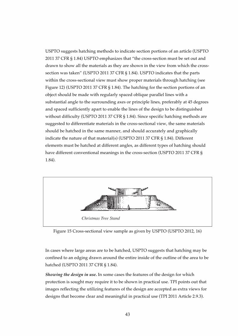
THE DEGREE OF MASTER OF SCIENCE IN
INDUSTRIAL DESIGN
SEPTEMBER 2012
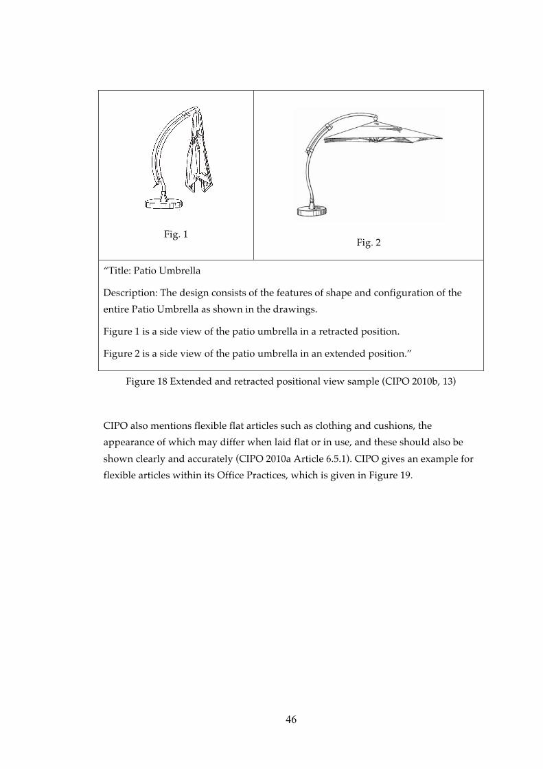
VISUAL REPRESENTATION IN INDUSTRIAL DESIGN REGISTRATION: A PROPOSED GUIDELINE FOR TURKEY BASED ON LEGAL TEXTS AND
GUIDELINES FROM EIGHT DIFFERENT JURISDICTIONS, AND INTERVIEWS WITH TURKISH PATENT INSTITUTE EXAMINERS
Submitted by IRMAK YALÇINER in partial fulfilment of the requirements for the degree of Master of Science in Industrial Design Department, Middle East Technical University by,
Prof Dr. Canan Özgen ______________
Dean, Graduate School of Natural Applied Sciences
Assoc. Prof. Dr. Gülay Hasdoğan ______________
Head of Department, Industrial Design
Assist. Prof. Dr. Fatma Korkut ______________
Supervisor, Industrial Design Dept., METU
Examining Committee Members:
Assist. Prof. Dr. Çağla Doğan ______________
Industrial Design Dept., METU
Assist. Prof. Dr. Fatma Korkut ______________
Industrial Design Dept., METU
Inst. Refik Toksöz ______________
Industrial Design Dept., METU
Assist. Prof. Dr. Aydın Öztoprak ______________
Industrial Design Dept. TOBB University
Inst. Dr. Gülçin Cankız Elibol ______________
Interior Architecture and Environmental Design Dept. Hacettepe University
Date: September 13, 2012
iii
I hereby declare that all information in this document has been obtained and presented in accordance with academic rules and ethical conduct. I also declare that, as required by these rules and conduct, I have fully cited and referenced all material and results that are not original to this work.
Name, Last Name: Irmak YALÇINER Signature :
iv
ABSTRACT
VISUAL REPRESENTATION IN INDUSTRIAL DESIGN REGISTRATION:
A PROPOSED GUIDELINE FOR TURKEY BASED ON LEGAL TEXTS AND
GUIDELINES FROM EIGHT DIFFERENT JURISDICTIONS, AND INTERVIEWS
WITH TURKISH PATENT INSTITUTE EXAMINERS
Yalçıner, Irmak
M.Sc., Department of Industrial Design
Supervisor: Assist. Prof. Dr. Fatma Korkut
September 2012, 178 pages
Visual representation is the most important element of a design registration in
terms of scope of protection. This study examines national, regional and
international design registration systems in terms of legal texts and guidelines
related to visual representation, investigates problematic issues concerning the
features and qualities of visual representation in industrial design registration
applications in Turkey through the interviews conducted with the Turkish Patent
Institute examiners, and proposes a guideline for Turkey which would assist
applicants and attorneys in preparing visual representations.
Keywords: Design protection, design registration, industrial design registration in
Turkey, visual representation of designs, guideline for visual representation,
examination of visual representation, preparation of visual representation.
v
ÖZ
ENDÜSTRİYEL TASARIM TESCİLİNDE GÖRSEL ANLATIM:
SEKİZ FARKLI HUKUK SİSTEMİNDEKİ DÜZENLEMELER VE KILAVUZLAR
İLE TÜRK PATENT ENSTİTÜSÜ UZMANLARIYLA YAPILAN GÖRÜŞMELER
TEMELİNDE TÜRKİYE’YE YÖNELİK BİR KILAVUZ ÖNERİSİ
Yalçıner, Irmak
Yüksek Lisans, Endüstri Ürünleri Tasarımı Bölümü
Tez Yöneticisi: Yrd. Doç. Dr. Fatma Korkut
Eylül 2012, 178 sayfa
Görsel anlatım, bir tasarım tescilinde koruma kapsamını belirleyen en önemli
unsurdur. Bu çalışma, ulusal, bölgesel ve uluslararası tasarım tescil sistemlerinde
görsel anlatıma ilişkin hukuki düzenlemeleri ve kılavuzları incelemekte, Türk
Patent Enstitüsü uzmanlarıyla yapılan görüşmelere dayanarak Türkiye’de
endüstriyel tasarım tescili başvurularında kullanılan görsel anlatımların
özelliklerine ve niteliklerine ilişkin sorunları araştırmakta ve görsel anlatımların
hazırlanmasında başvuru sahiplerine ve vekillere yardımcı olacak bir kılavuz
önermektedir.
Anahtar Kelimeler: Tasarım koruması, tasarım tescili, Türkiye’de endüstriyel
tasarım tescili, tasarımların görsel anlatımı, görsel anlatım kılavuzu, görsel
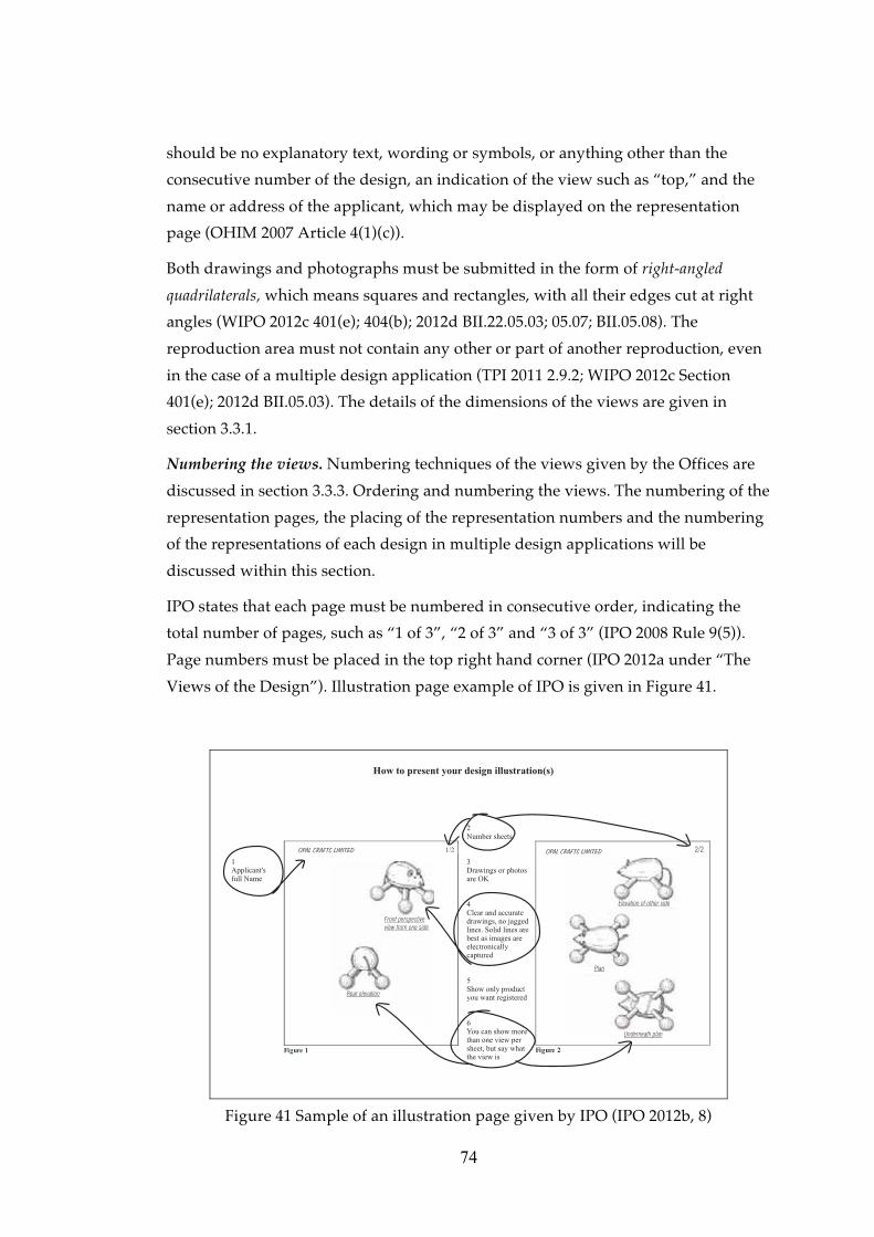
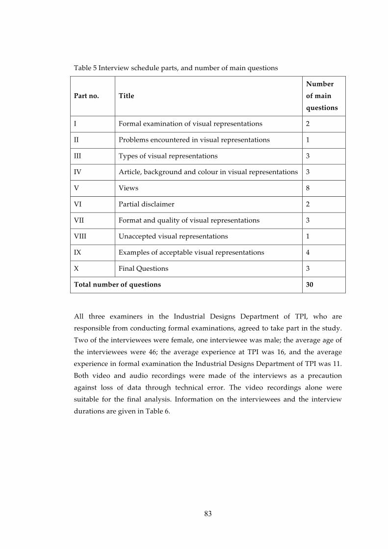
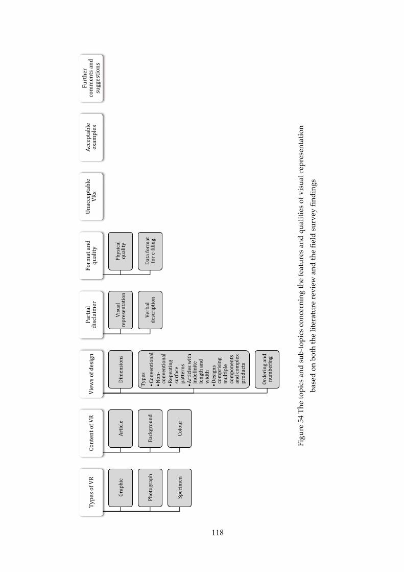
Figure 54 The topics and sub-topics concerning the features and qualities of visual
representation based on both the literature review and the field survey findings118
xvii
LIST OF ABBREVIATIONS
Administrative
Instructions Administrative Instructions for the Application of the Hague Agreement
CDIR
COMMISSION REGULATION (EC) No 2245/2002 of 21 October 2002 implementing Council Regulation (EC) No 6/2002 on Community designs (OJ EC No L 341 of 17.12.2002, p. 28) amended by Commission Regulation (EC) No 876/2007 on 24 July 2007 amending Regulation (EC) No 2245/2002 implementing Council Regulation (EC) No 6/2002 on Community designs following the accession of the European Community to the Geneva Act of the Hague Agreement concerning the international registration of industrial designs
(OJ EC No L 193 of 25.7.2007, p. 13)
CDR
COUNCIL REGULATION (EC) No 6/2002 of 12 December 2001 on Community designs (OJ EC No L 3 of 5.1.2002, p. 1) amended by Council Regulation No 1891/2006 of 18 December 2006 amending Regulations (EC) No 6/2002 and (EC) No 40/94 to give effect to the accession of the European Community to the Geneva Act of the Hague Agreement concerning the international registration of industrial designs
(OJ EC No L 386 of 29.12.2006, p. 14)
CIPO Canadian Intellectual Property Office
Common
Regulations Common Regulations under the 1999 Act and the 1960 Act of the Hague Agreement
Directive Directive 98/71/EC of the European Parliament and of the Council of 13 October 1998 on the legal protection of designs
Council
Regulation
COUNCIL REGULATION (EC) No 6/2002 of 12 December 2001 on Community designs (OJ EC No L 3 of 5.1.2002, p. 1) amended by Council Regulation No 1891/2006 of 18 December 2006 amending Regulations (EC) No 6/2002 and (EC) No 40/94 to give effect to the accession of the European Community to the Geneva Act of the Hague Agreement concerning the international registration of industrial designs (OJ EC No L 386 of 29.12.2006, p. 14)
Decree-Law Turkish Decree-Law no. 554 Pertaining to the Protection of the
xviii
No. 554 Industrial Designs of June 27, 1995 amended by the Law No. 4128
of November 7, 1995
Implementing
Regulation of
Decree-Law
Implementing Regulation under Turkish Decree-Law no. 554
Pertaining to the Protection of the Industrial Designs of June 27,
1995
IP Australia Australian Intellectual Property Office
IPO Intellectual Property Office of United Kingdom
TPE Türk Patent Enstitüsü (See TPI)
TPI Turkish Patent Institute
KIPO Korean Intellectual Property Office
OHIM Office of Harmonization for the Internal Market
PEM Patent and Trademark Attorneys’ Association of Turkey
RCD Registered Community Design
USPTO United States Patent and Trademark Office
WIPO World Intellectual Property Organization
1
CHAPTER 1
INTRODUCTION
1.1 Background and motivation
Design registration is a system put in place for the protection of designs within the
industrial property branch of the intellectual property system. In respect of the
principle of territoriality, in Turkey designs are protected by the Decree-Law and
the Implementing Regulation under the Decree-Law that aims to protect designs by
giving exclusive rights to the right holders to facilitate the formation and
development of industry in a fair but competitive environment.
After being awarded a Bachelor of Arts degree in graphic design, I started working
in an intellectual property agency in 2006. Serving clients in the protection of their
industrial property rights and working as a court expert for the specialized
intellectual property courts has allowed me to observe a number of problems
related to the visual representation of designs, such as representing a three-
dimensional design with a single view, or using low resolution images which fall
short of representing the details of the design for which protection is sought. Since
registered industrial designs are protected on the basis of their visual representation
and description, and the visual representation is the “key element of the design
right to be established” (TPI 2011 Article 2.9), the problems in the representations
that attracted my attention, not only as an attorney and court expert but also as a
graphic designer, represent a crucial flaw in the industrial design registration
system.
Hasdoğan mentions that inadequate visual representations are one of the major
problems observed in design registrations in Turkey, and are a key aspect in the
falling through of court actions related to design protection (Hasdoğan 2005, 344;
348). Elibol suggests that the visual representation requirements of designs should
be standardised (Elibol 2011, 139). It is the applicant’s responsibility to provide
adequate representation, including a sufficient number of views so as to represent
all of the features of the design to be protected (TPI 2011 Article 2.9). However there
are no specialized checklists or guidelines published by the Turkish Patent Institute
2
for applicants, or their representatives or attorneys, which cover all the requisite
elements of the visual representations and offer advice during the application
preparation stage. Consequently, a study to come up with such a document is
imperative in the industrial design registration field in Turkey.
1.2 Aim and scope of the thesis
The aim of this study is to examine national, regional and international design
registration systems in terms of legal texts –which include legislations, by-laws and
agreements- and guidelines related to visual representation, to investigate
problematic issues concerning the features and qualities of visual representation in
industrial design registration applications in Turkey, and to develop a guideline
which would assist applicants and attorneys in preparing visual representations.
The key questions of this research are as follows:
• What is visual representation as it is defined in national, regional and
international design registration systems?
• What are the features and qualities of visual representation as described in legal
texts and guidelines in national, regional and international design registration
systems?
• How does the Turkish Patent Institute examine the visual representations? Are
there any internal examination guidelines, checklists or procedures used for the
examination of visual representations?
• What are the critical and problematic issues observed by the Turkish Patent
Institute concerning the features and qualities of visual representations in
industrial design registration applications in Turkey?
• What are the elements of a guideline, which would assist applicants and
attorneys in preparing visual representations for industrial design registration
applications in Turkey?
1.3 Structure of the thesis
In the first chapter, the research topic, background, motivation and aim of the study,
and the key research questions are explained.
Chapter 2 contains the first part of the literature review, which introduces the study
area in general from a legal perspective by explaining and comparing the definitions
of “industrial design” and “visual representation” within the surveyed jurisdictions.
3
The importance and the problems of the visual representation in design registration
systems are also explained in this chapter.
Chapter 3 is the second part of the literature review, which explores the features and
qualities of visual representations as described in the legal texts and guidelines in
national, regional and international design registration systems. The findings are
discussed and presented in a categorized form addressing topics and issues relevant
for a guideline for visual representation.
After the categorization of the literature survey findings and forming the main
topics and sub topics of the guideline to be developed, a field study was conducted
of the practitioners responsible for the examination of visual representations in the
field of industrial design registration in Turkey –the design examiners of the TPI.
Chapter 4 presents the field study and discusses the findings concerning the main
problems in visual representations from the perspective of the design examiners at
TPI. This chapter helps to understand the problematic areas and issues in visual
representations in industrial design registration applications in Turkey together
with the suggestions of the examiners, and the eligibility of significant and unusual
literature survey findings for adaptation and adoption into the Turkish design
protection system.
Drawing upon the findings of both the literature review and the field study,
Chapter 5, the concluding chapter, proposes a guideline, which assists design
attorneys and applicants in preparing visual representations for industrial design
registration applications in Turkey.
4
CHAPTER 2
LITERATURE REVIEW PART I:
INDUSTRIAL DESIGN REGISTRATION AND VISUAL REPRESENTATION
2.1 Strategies and limitations of the literature review
The purpose of the literature review in this study is to explore visual representation
in industrial design registration from a legal perspective, and to investigate legal
texts and guidelines within the scope of visual representation in Turkey, as well as
in other national, regional and international design registration systems.
The general keywords used during the literature survey, mainly of legal literature,
are as follows:
• Design law. Design and industrial design registration, design legislation,
industrial or handicraft item, including inter alia parts intended to be assembled
into a complex product, packaging, get-up, graphic symbols and typographic
typefaces, but excluding computer programs”. It is described as a product
composed of multiple components, which can be replaced by disassembly and re-
assembly of the product within the Counsel Regulation (OHIM 2007 CDIR Article
3(c)). The UK industrial design registration system defines product in the same way
1 Decree Law No. 554 Article 3/1(a) and (b)
12
as OHIM in the Registered Designs Act Article 1/3, as “any industrial or handicraft
item other than a computer program; and, in particular, includes packaging, get-up,
graphic symbols, typographic type-faces and parts intended to be assembled into a
complex product”. The UK Registered Designs Act defines a complex product as “a
product which is composed of at least two replaceable component parts permitting
disassembly and reassembly of the product” in Article 1/3, as same definition as in
the Australian Design Act Section 5 (IP Australia 2003).
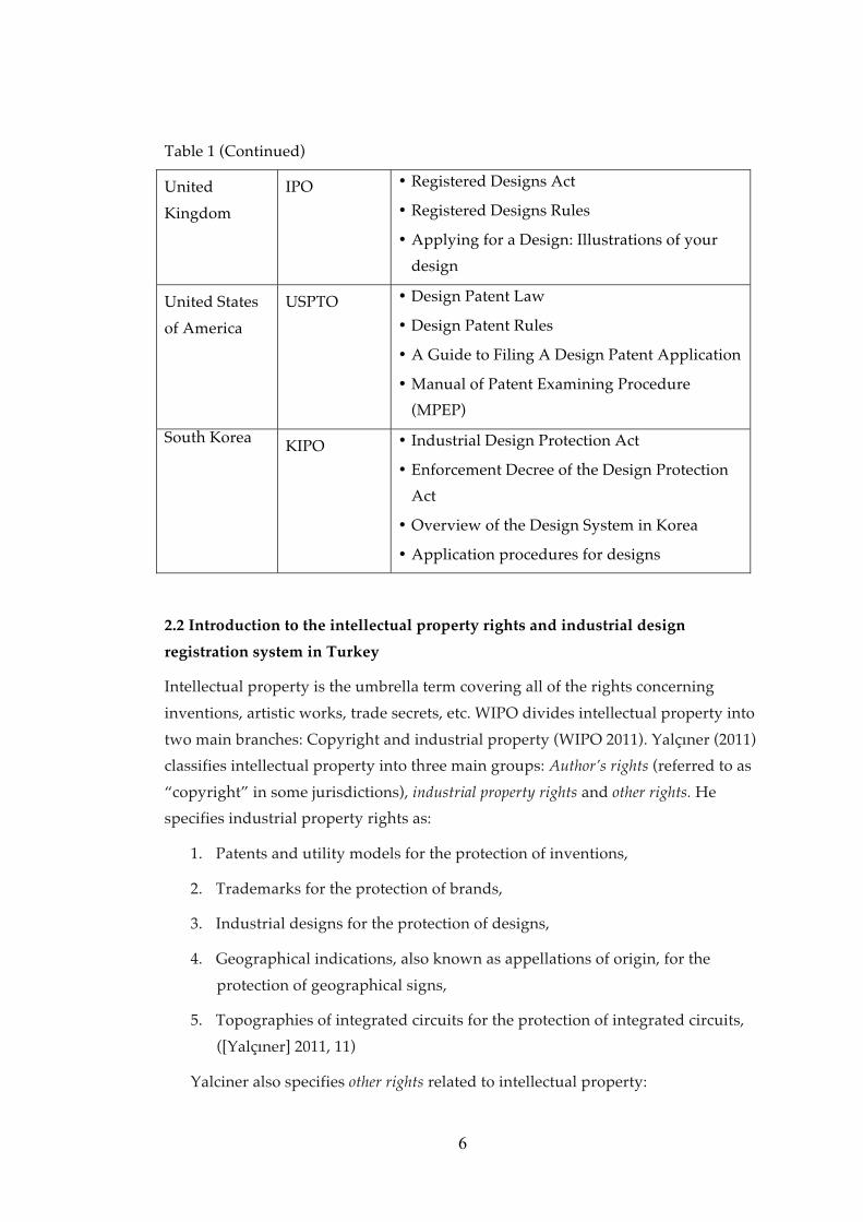
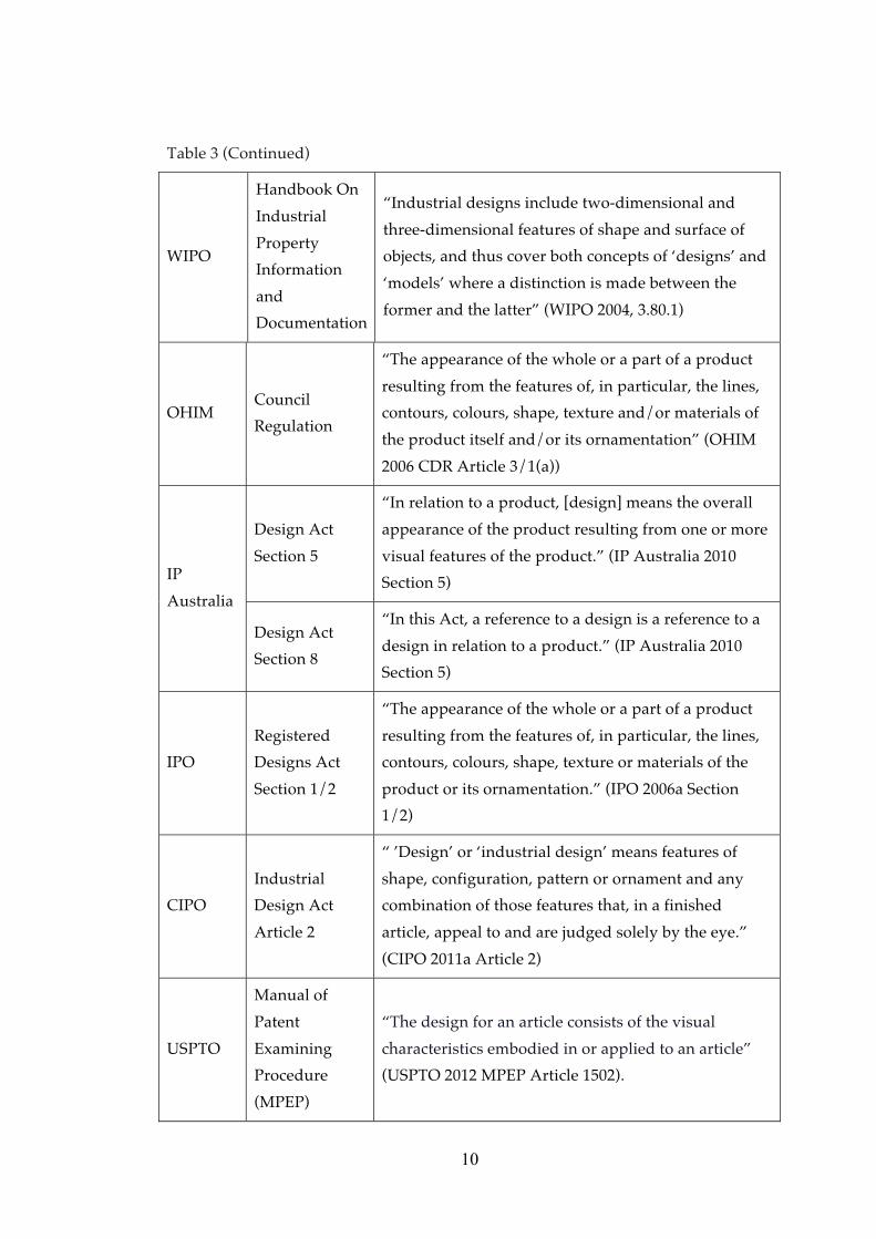
According to WIPO's definitions and explanations the aim of registered design
protection is to protect the visual features of a design in all of the member states.
The Handbook on Industrial Property Information and Documentation indicates
that the term “industrial design” does not refer to patents or supplementary
protection certificates (SPC) specified in the WIPO Standard ST.9 (WIPO 2004 under
“Definitions”). In the United States of America, registered designs are protected
within the Patent Rules and Laws and called “design patents”; however it is
explained that design patent’s scope of protection only covers the appearance of the
article, disregarding its structural or utilitarian features (USPTO 2011 under the
“Definition of a Design”). The functionality, construction methodology or other
such qualifications cannot be protected with design registration or design patents,
and therefore it is the design’s visual qualities and features that are reflected within
the visual representations that are protected by design registration.2
2.4 Definition of “visual representation” in the reviewed legal texts and
guidelines
The visual representation of a registered design means “to specify the features of the
design for which protection is sought” according to OHIM, which states further that
it is of utmost importance that the representation be clear and complete, and that
nothing regarding the design is left conjecture (OHIM 2012 Ch. 4.4). Current
regulations in Turkey3 describes visual representation as the visual appearance of
the product in which the design is incorporated, or to which it is applied, prepared
in a drawing, picture, graphic, photograph or some other medium, specifying that it
must clearly show all special characteristics of the design and must be suitable for
reproduction through publication (TPI 2009 Article 26/1(b)). IPO, in the Registered
Design Rules, defines “suitable for reproduction” as suitable for publication (IPO
2 The definitions of design covered in this section give reference to visual features and qualities; the legislations of Canada and South Korea refer to the sense of sight directly. The Turkish legislation, on the other hand, implies a wider scope covering the qualities and features “perceived by the human senses”. 3 Decree Law No. 554 and Implementing Regulation
13
2006b Rule 9/5). WIPO describes visual representation in its Common Regulations
as “reproductions,” and explains “they shall be in the form of photographs or other
graphic representations of the industrial design itself, or of the product or products
which constitute the industrial design” (WIPO 2012, Rule 9).
The Australian Design Act defines the form of visual representation in the definition
section as drawings, tracings or specimens (IP Australia 2003, Ch.1, Part 2, Sec. 5).
As a non-legislative text, IPO’s “Illustrations of your design” offers a guideline for
applicants, and states that the representation should be an “accurate and complete
picture of the design,” and divides the suggested form of visual representations into
drawn views and photographic views (IPO 2012a under “Illustrations of your
design”). Another non-legislative text from CIPO is the guideline suggesting visual
representations in the form of drawings and photographs (CIPO 2012a under
“Preparing an Industrial Design Application”). As mentioned previously, in the
United States of America, designs are protected within patent law as design patents,
and accordingly, USPTO 37 C.F.R. § 1.152 refers to patent drawings, and mentions
types of drawings and photographs. The Korean design registration system also
cites forms of visual representation, defining drawings and photographs in the
Design Act. The forms of visual representation specified in the reviewed legal texts
and guidelines are given in Table 4.
Table 4 Forms of visual representation in the reviewed legal texts and guidelines
Authority Legal Text or
Guideline Forms of Visual Representation
TPI Decree Law
Article 26/1(b)
Drawing, picture, graphic, photograph or similar
representation of the design suitable for reproduction
WIPO
Common
Regulations
Rule 9
Photographs or other graphic representations
14
Table 4 (Continued)
OHIM
Council
Regulation
Article 36/1(c)
CDIR Article
4(1)
Representation of the design suitable for reproduction
Graphic or photographic reproduction of the design
IP
Australia
Design Act
2003 Ch.1, Part
2, Sec. 5
Drawing, tracing or specimen
IPO
The Registered
Design Rules
2006 Rule 9/5
“Illustrations
of your
designs” (non-
legislative)
“Suitable representation,” meaning a representation
of the design that is suitable for publication
Accurate and complete picture of the design
Drawn views or photographic views
CIPO
Industrial
Design Act
Article 4
Drawing or photograph of the design
USPTO
37 C.F.R. §
1.152 refers to
37 C.F.R. § 1.84
Drawing and photograph
KIPO
Industrial
Design
Protection Act
Article 5/1
Drawing (3D-modelling drawing also mentioned) and
photograph
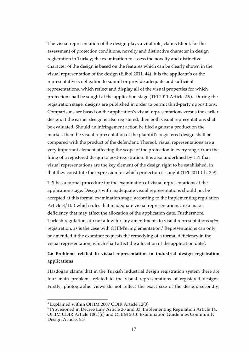
2.5 Importance of visual representation in industrial design registration
Design registration in Turkey consists of three main stages: Application, registration
and post-registration (Figure 1). The visual representation of a design has an
important role in terms of the scope of protection in all these stages. During the
15
application stage at which the formal examination takes place, inadequate visual
representations may result in formal deficiencies. After the formal examination the
registration stage starts. During the registration stage, the design registration
application is published in the Official Industrial Design Bulletin, and third parties
may file an opposition against the registration within six months. The visual
representation of the design plays a critical role in the case of an opposition that
involves the comparison of the design with earlier designs. During the post-
registration stage, invalidity or infringement actions also involve the comparison of
the visual representation of a registered design with earlier designs.
Figure 1 Stages of a design registration in Turkey and the procedures where the
visual representation plays an important role.
WIPO states that if the applicant wishes to obtain maximum protection for their
design, they should ensure that the design is fully represented, as only the aspects
that are visibly represented shall be protected (WIPO 2012c BII.22.05.10).
Visualizing the design for registration is important in the industrial design
protection system in Turkey. Implementing regulation in Turkey deems that a
registered design shall be protected by the visual representations and descriptions
filed at the application stage (TPI 2005 Article 9/1(a)). According to OHIM the
description of the design cannot contain any reference to features that cannot be
seen in the visual representation (OHIM 2012 Ch. 9.2), meaning that the features
that cannot be seen in the visual representation will fall outside the scope of the
protection.
If the visual representation does not fulfil the requirements specified in the legal
texts, it may affect the application date or may be ground for the refusal of an
16
application. OHIM rules that an application date cannot be granted if the
representation of the design:
• is not in jpeg data format in electronic filing applications,
• is submitted without a neutral background, or has been retouched using ink
or correction fluid, or
• if the visual quality is not sufficient for displaying all of the details of the
design for which protection is sought (OHIM 2007 CDIR Article 4(1)(d);
Article 4(1)(e); Article 10(1)(c) and OHIM 2012 Ch. 4.4).
In the Turkish legislation visual representation(s) are a mandatory requirement for
the application date to be granted. Decree Law Article 26/1(b) contains the
following provision: “An application for registration of a design must be filed with a
drawing, painting, graphic, photographic or similar representation of the design
suitable for reproduction and reflecting all of its specific features”. KIPO also
indicates the representation of the design must be submitted at the same time of
filing the design application (KIPO 2011 under “Application Procedure for
Designs”).
Contracting Parties of the Hague Agreement (1999 and 1960 Acts) have the right to
refuse an international design registration application on the grounds that the
reproductions of the design are not sufficient to disclose the industrial design fully
(WIPO 2012b Rule 4). Additionally, corrections that change the representations are
not permitted according to Community Design Regulations (OHIM 2007 CDIR
Article 12(3) and OHIM 2012 Ch. 13.2). A description is also filed together with the
visual representation, however, as stated by KIPO, “the description of a design is
not as important as the specification of a patent or utility model application, so long
as drawings of the design are correctly and properly prepared” (KIPO 2011 under
the “Application Procedure for Design”). Therefore, it is very important to prepare
and submit the correct representations of the design to be protected while filing the
application.
It is very important to show all the new features of the design on the representation
to ensure that they are enforceable in any legal dispute (IPO under Design practice
notice (DPN) 6/06, 6/03). IPO emphasizes that the purpose of the representations
and specimens is to present an accurate and complete picture of the design to be
registered, and also to identify those features of the design which are novel and for
which protection is sought (IPO under Design practice notice (DPN) 1/04).
17
The visual representation of the design plays a vital role, claims Elibol, for the
assessment of protection conditions, novelty and distinctive character in design
registration in Turkey; the examination to assess the novelty and distinctive
character of the design is based on the features which can be clearly shown in the
visual representation of the design (Elibol 2011, 44). It is the applicant’s or the
representative’s obligation to submit or provide adequate and sufficient
representations, which reflect and display all of the visual properties for which
protection shall be sought at the application stage (TPI 2011 Article 2.9). During the
registration stage, designs are published in order to permit third-party oppositions.
Comparisons are based on the application’s visual representations versus the earlier
design. If the earlier design is also registered, then both visual representations shall
be evaluated. Should an infringement action be filed against a product on the
market, then the visual representation of the plaintiff’s registered design shall be
compared with the product of the defendant. Thereof, visual representations are a
very important element affecting the scope of the protection in every stage, from the
filing of a registered design to post-registration. It is also underlined by TPI that
visual representations are the key element of the design right to be established, in
that they constitute the expression for which protection is sought (TPI 2011 Ch. 2.9).
TPI has a formal procedure for the examination of visual representations at the
application stage. Designs with inadequate visual representations should not be
accepted at this formal examination stage, according to the implementing regulation
Article 8/1(a) which rules that inadequate visual representations are a major
deficiency that may affect the allocation of the application date. Furthermore,
Turkish regulations do not allow for any amendments to visual representations after
registration, as is the case with OHIM's implementation.4 Representations can only
be amended if the examiner requests the remedying of a formal deficiency in the
visual representation, which shall affect the allocation of the application date5.
2.6 Problems related to visual representation in industrial design registration
applications
Hasdoğan claims that in the Turkish industrial design registration system there are
four main problems related to the visual representations of registered designs:
Firstly, photographic views do not reflect the exact size of the design; secondly,
4 Explained within OHIM 2007 CDIR Article 12(3) 5 Provisioned in Decree Law Article 26 and 33, Implementing Regulation Article 14, OHIM CDIR Article 10(1)(c) and OHIM 2010 Examination Guidelines Community Design Article. 5.3
18
submitting one photographic view and one technical representation (graphic
representation) of the design prohibits an understanding of the three dimensional
features of the design; thirdly, designs photographed in an embroiling composition,
such as displaying all the elements of a set of furniture in one representation; and
finally, partial disclaimer cases where the part(s) of the product for which protection
are sought are not indicated or shown clearly (Hasdoğan 2005, 348).
Elibol also cites insufficient visual representations as one of the problems when
making an assessment of the novelty and distinctive character of the design to be
protected, stating “Good quality visual representation would facilitate the
assessment” (Elibol 2011 144; 167).
Common problems at the application stage related to the visual representations in
the UK are described in Design Practice Notice 1/04 as follows:
• More than one design is shown in the visual representations.
• Representations include dimensions and other technical drawing features,
which obscure the design.
• The examiner is unable to identify the design from the representations given
(IPO 2004 DPN 1/04).
19
CHAPTER 3
LITERATURE REVIEW PART II: FEATURES AND QUALITIES OF VISUAL REPRESENTATION AS
DESCRIBED IN LEGAL TEXTS AND GUIDELINES
All of the legal text and guidelines of national, regional and international design
registration systems cited in Table 1 are analysed by first selecting the parts related
to the visual representations of design registrations for classifying the main features
and qualities of the visual representations. Afterwards, each sentence within the
surveyed parts that describes a feature of a visual representation is highlighted to
allow an easy comparison of the common issues in different jurisdictions. The
analysis continued by printing and cutting out the highlighted statements, and
grouping them under potential topics in respect to the features and qualities
covered. This categorization and grouping is done by preparing a board for each
topic and mapping the highlighted parts according to each topic and sub-topic on a
separate board. An example of one of the boards prepared for the “Physical quality”
topic is given below.
20
Figu
re 2
Cat
egor
izat
ion
boar
d fo
r th
e “P
hysi
cal q
ual
ity”
top
ic
21
As given in Figure 2, the findings, which explain the physical quality of the visual
representations, are extracted from the document and pasted on the board, which
the example is the board prepared for the “Physical quality” sub-topic under
“Format and Quality of Visual Representation” topic. Colour codes were given for
common features or qualities, i.e. green is used for the explanations on size and
quality of the paper and blue is used for the clarifications on size of the
representation.
Subsequently, after analysing the legal text and guidelines of the eight jurisdictions,
including that of Turkey, six main topics were identified: types of representation,
content of visual representation, views of the design, partial disclaimer, format and
quality of visual representation and unacceptable visual representation. All the
topics of features and qualities of visual representation are given in Figure 3 and
each topic is explained in below.
Figu
re 3
The
list
of t
opic
s an
d s
ub-
top
ics
of th
e fe
atu
res
and
qu
alit
ies
of v
isu
al r
epre
sent
atio
n
����������� ��
��������� �����
�� �����
��������� �����
������� ���
���������
������������� ��
��������� �����
��������
� ���������
�������
��� �����������
!����������
������
" ��������� ��
" #��$��������� ��
" ���� �������� ���
� �������
" ��������� ����
����%�������������
��� �����
" !�������
�����������
���������
����������� ���
������&����������
'�������� ���
���(������
� ��� ��
����� �����
���� ��
��������� �����
���( ��
������������
)��� �� ���
*� �����
������ ��*� �����
! � ���� �����
�$%������
+� ����� (���
��� ��
��������� ������
22
23
3.1 Types of Representation
Visual representations are categorized into three main groups: Graphic
representations, photographs and specimen.
1. Graphic representation which includes drawings, ink drawings, and or similar
it must be clearly understandable from the representation exactly which elements
protection is sought for in designs made up of a combination of the features of the
articles and adds “such combinations may arise e.g. where the articles of the set are
so closely related that they can be considered as forming a single product,” for
example forks, spoons and knives (OHIM 2012 Article 5.1). It is important to include
at least one view that shows the product as a whole in representations of designs
comprising multiple components, such as with all the components assembled,
otherwise the design representations are perceived as multiple design applications,
not as a single design application with multiple components (OHIM 2012 Article
5.1). A single application comprising multiple designs may result in a formal
deficiency (OHIM 2012 5.1 and 11.4).
CIPO indicates that all of the pieces of the set of articles must be shown within the
drawings and photographs (CIPO 2010a Article 6.5.1).
10 According to Turkish legislation Decree Law Article 28 it may be possible to file several designs in one application, so long as they all belong to the same sub-class, the same set or are parts of the same item.
61
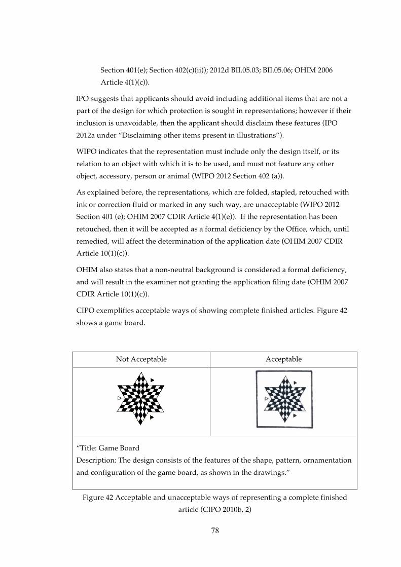
“Title: Set of flatware
Description: Design comprises features of ornamentation applied to the outer
portion of the handles of the set of flatware, as shown in the drawings.
Fig. 1 is a front view of the spoon, fork and knife of the set of flatware”
Figure 32 Representation sample of a set of flatware design (CIPO 2010b, 23).
USPTO states that designs with multiple embodiments of a single concept can be
filed in a single design patent application, so long as they are similar in appearance
and shape, as given in the example below (USPTO 2012 under “Multiple
Embodiments”).
62
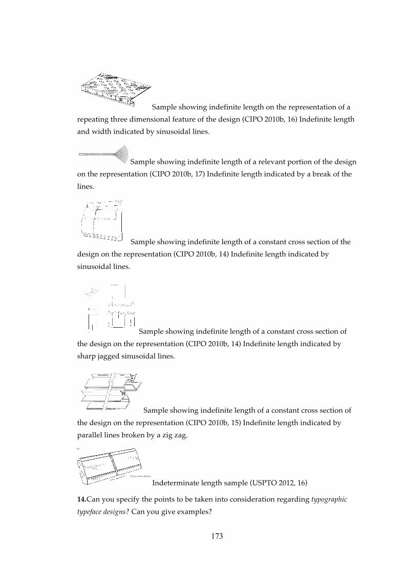
“ Combined Writing Instrument and Pocket Holder”
Figure 33 Visual representation sample of a design with multiple embodiments of a
single concept (USPTO 2012, 16)
Representation of a complex product. In cases where the applicant would like to
register a component part of a complex product11 it is important to submit views of
the product incorporated into a complex product in such a way that those parts
which are novel and have individual character remain visible in the normal use12 of
that complex product (IPO 2003 Design Practice Notices (DPN) 1/03). All of the
internally visible features, such as steering wheel, seats and dashboard, shall be
visible in normal use, as well as the externally visible features of the complex
product, such as the overall contours, ornamentation of grille badges, door handle,
wheel trims etc. (IPO 2003 Design Practice Notices (DPN) 1/03).
Only USPTO emphasizes that when the protection claim is for the entire article, but
when all sides of the entire article are not visible in normal use, it is not necessary to
disclose all of them (USPTO 2012 under “The Views”).
11 Definitions of product and complex product is given in section 2.3 12 Normal use is defined as use by the end user by the IPO Registered Designs Act 1949 (c.88) as amended Section 1B(9). The Design Practice Notes exemplified the end user of a motor car as being the owner or the driver rather than the service mechanic (IPO 2003 Design Practice Notices (DPN) 1/03).
63
3.3.3 Ordering and numbering the views
Total number of views. TPI, WIPO and KIPO declare that there is no limitation on
the number of submitted views (TPI 2011 Article 2.9.3; WIPO 2012d BII.05.10; KIPO
2011 under “Overview of the design system in Korea”).
WIPO states that no contracting party may require more than one view of a design
where the design or the product is two dimensional, and more than six views where
the design or the product is three-dimensional (WIPO 2012b Rule 9/3(b)). CIPO
indicates “at least one drawing or photograph is required that is of sufficient clarity
to see the article and the design” (CIPO 2010a Article 2.4) KIPO says it is up to the
applicant how many views they submit with a design application, although it is
suggested to submit a perspective and a set of six views (KIPO 2011 under the
“Overview of the Design System in Korea”). OHIM, on the other hand, sets a limit
of seven views for each design, and adds that submissions of extra views that exceed
this limit will be disregarded by the Office (OHIM 2003 Article 4; 2007 CDIR Article
4(2); 2012 Article 11.4).
TPI applies no limitation to the number of representations, however the examiner
shall be ensure that the submitted representations display clearly all the distinctive
visual features of the design for which protection is sought (TPI 2011 Article 2.9.3).
OHIM emphasizes that there must be a sufficient number of views submitted to
specify all the features of the design for which protection is sought, as the examiner
will not check whether the design has features other than those shown in the
submitted views (OHIM 2012 Article 11.4). IPO states that if the design is three-
dimensional, then the representations should include a series of views from
different angles to show the overall appearance of the design (IPO 2012a under
“Illustrations of your designs”). CIPO and IPO also mentions that there must be
sufficient number of views, which shows the article clearly and accurately, so as to
leave no doubt when understanding the design features for which protection is
CIPO indicates that the number of views must be sufficient to show clearly and
accurately the features of the design (CIPO 2010a Article 6.5.1).
USPTO indicates that the number of views must be sufficient to facilitate complete
disclosure of the appearance of the claimed design (USPTO 2010 37 CFR § 1.152;
2012 under “The Views”). USPTO’s “A Guide to Filling a Design Patent
Application” explains that “The drawings or photographs should contain a
sufficient number of views to completely disclose the appearance of the claimed
design, i.e., front, rear, right and left sides, top and bottom. While not compulsory, it
64
is suggested that perspective views be submitted to clearly show the appearance
and shape of three-dimensional designs. If a perspective view is submitted, the
surfaces shown would normally not be required to be illustrated in other views if
these surfaces are clearly understood and fully disclosed in the
perspective.”(USPTO 2011 under “The View”).
Arrangement of the views. WIPO, CIPO and USPTO clarify how the views should
be arranged in the design application. WIPO states that representations must be
arranged in the order that the applicant wishes them to be published (WIPO 2012c
Section 401(d)); while CIPO states that grouping views according to each variant13 is
preferred (CIPO 2010a Article 6.5.1).
USPTO requests the physical arrangement of the views on sheets be made as
follows:
• One view must not be placed upon another, or within the outline of another,
• All views on the same sheet should stand in the same direction, preferably in
an upright position (USPTO 2010 37 CFR § 1.84) (See section 3.5.1 Physical
quality for details of the quality of the representations).
USPTO indicates that it is preferable for the order of the views to be as they appear
on the drawing sheet(s) (USPTO 2010 37 CFR § 1.84).
Numbering and labelling the views. WIPO emphasizes that for non-electronic filing
(i.e. paper submission applications), each design must be identified by an individual
number, appearing in the margin of each representation, and states that the
electronic filing interface adds numbering automatically (WIPO 2012d BII.05.11); it
is also important that representations contain no numbering (WIPO 2012d BII.05.03).
The numbering of the additional views is similarly specified by OHIM and WIPO.
All additional views for each design are numbered with two digits separated by a
dot. The first indicates the design, and the second indicates the number of the view
(e.g. the 7th view of a design numbered 3 shall be numbered 3.7) (OHIM 2007 CDIR
Article 4(2) and OHIM 2012 Article 11.4). WIPO states that the design represented
from different angles must be numbered with two digit numbers, i.e. 1.1, 1.2, 1.3 …
etc., for the first design; and 2.1, 2.2, 2.3… etc., for the second design (WIPO 2010
BII.22.05.11).
13 “Variant: An application must relate to one design or to designs that constitute variants. To be accepted as variants, the designs must be very similar and possess the described features without substantial variation.” (CIPO 2011a Article 6.4.5 (e))
65
USPTO says that views must be numbered in consecutive order with simple and
clear Arabic numerals, starting from one, and without brackets, circles or inverted
CIPO suggests that the numbers of views should be in sequence, and should be
written, stamped or typed on the rear of the photograph using permanent ink (CIPO
2010a Article 6.5.1).
IPO indicates that views should be labelled and exemplifies the labelling of views as
“front view”, “view on one side” and “perspective view from front, above and one
side” (IPO 2012a under “Labelling the views”).
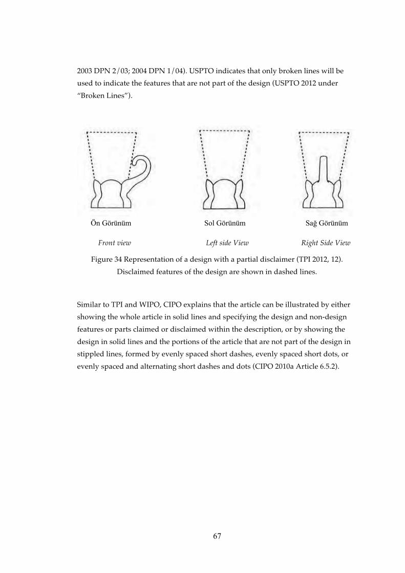
3.4 Partial Disclaimer
A design registration is not always requested for the whole article or product, as in
some cases the applicant is seeking to limit or extent the scope of protection of a
design. For this reason, protection can be also requested for only a part of a design
(TPI 2011 Article 2.9.2).
IPO states that a design registration may be accompanied by a disclaimer that:
• limits or extent the scope of protection being applied for in relation to the
design, or
• indicates that the application for registration relates to a design that forms
only a part of the appearance of a product (IPO 2006b Rule 6).
If the applicant wishes to protect the design of only a part of a product, or to
disclaim visual features such as colours or materials, a partial disclaimer must be
used (IPO 2012 “Partial disclaimers”). A partial disclaimer can also be used in cases
where the applicant wishes to protect a specific feature of the design, such as the
three-dimensional shape but not the surface decoration (IPO 2012a under “Partial
Disclaimer”).
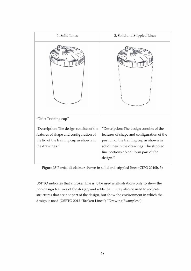
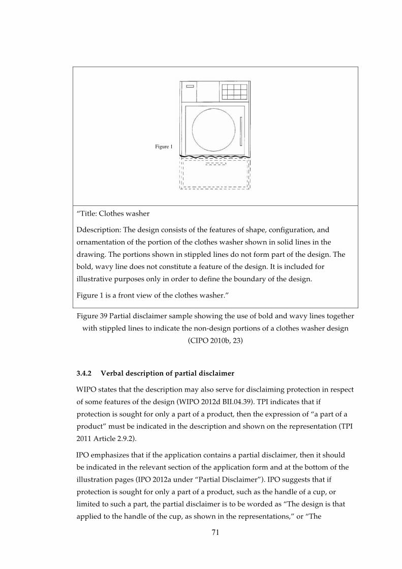
WIPO expresses that the disclaimer must be indicated within the description
and/or within the representation by means of dotted or broken lines (WIPO 2012c
Section 403; 2012d BII.05.09). Partial disclaimers shall be evaluated by the examiner
from two parts of the application: visual materials, showing the disclaimer on the
representation; and written statements, indicated in the description. There are three
features of the application cited by TPI that must comply with each other:14
14 It is the examiner’s responsibility to ensure the conformity of these three features of the design with each other in relation to the element for which protection is being sought (TPI 20122 Article 2.9.2).
66
Indication of the product, representation, and written description (TPI 2011 Article
2.9.2). Those three features must be in combination in the applications where the
partial disclaimer is requested as well.
3.4.1 Visual representation of a partial disclaimer
TPI states that the parts for which protection is requested shall be clearly marked on
Figure 48 Visual representation of a sliding system profile design for furniture
Interviewee 3 stated that according to the latest court decisions, cross-sectional
views are not accepted in court procedures if the product is a complex product. He
cited that a court has decided that invisible parts of complex products, such as
profiles of window or balcony systems, cannot be protected. However, he added
that TPI accepts such cross-sectional views as additional views to a three-
dimensional view of the design. He gave the example of a tyre design, and indicated
that the tyre treads can be understood from their cross-sectional views, which are
mainly filed by foreign applicants.
Interviewee 3 stated that cross-sectional views, except for profile designs, are not
acceptable. He indicated that the design registration system protects only the
appearance of the design, and gave the example of foodstuff designs, which may be
filed by cross sectional view in order to show the inner structure of the food as an
additional view. Cross-sectional views of such foodstuff designs are not acceptable.
Views showing the design in use. Interviewees 1 and 3 indicated that views showing
the design in use are acceptable. When the researcher gave the example of a design
for a sofa, which can be converted to a bed, Interviewees 1 and 3 indicated that the
view of the sofa as converted to bed is an additional view, showing the design in
use. Interviewee 3 underlined that there is only one article, a sofa, which can be
converted to a bed, and so the sofa configuration and the bed configuration views of
the same article should not be filed as additional designs. However, Interviewee 1
102
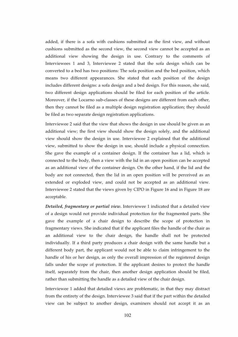
added, if there is a sofa with cushions submitted as the first view, and without
cushions submitted as the second view, the second view cannot be accepted as an
additional view showing the design in use. Contrary to the comments of
Interviewees 1 and 3, Interviewee 2 stated that the sofa design which can be
converted to a bed has two positions: The sofa position and the bed position, which
means two different appearances. She stated that each position of the design
includes different designs: a sofa design and a bed design. For this reason, she said,
two different design applications should be filed for each position of the article.
Moreover, if the Locarno sub-classes of these designs are different from each other,
then they cannot be filed as a multiple design registration application; they should
be filed as two separate design registration applications.
Interviewee 2 said that the view that shows the design in use should be given as an
additional view; the first view should show the design solely, and the additional
view should show the design in use. Interviewee 2 explained that the additional
view, submitted to show the design in use, should include a physical connection.
She gave the example of a container design. If the container has a lid, which is
connected to the body, then a view with the lid in an open position can be accepted
as an additional view of the container design. On the other hand, if the lid and the
body are not connected, then the lid in an open position will be perceived as an
extended or exploded view, and could not be accepted as an additional view.
Interviewee 2 stated that the views given by CIPO in Figure 16 and in Figure 18 are
acceptable.
Detailed, fragmentary or partial view. Interviewee 1 indicated that a detailed view
of a design would not provide individual protection for the fragmented parts. She
gave the example of a chair design to describe the scope of protection in
fragmentary views. She indicated that if the applicant files the handle of the chair as
an additional view to the chair design, the handle shall not be protected
individually. If a third party produces a chair design with the same handle but a
different body part, the applicant would not be able to claim infringement to the
handle of his or her design, as only the overall impression of the registered design
falls under the scope of protection. If the applicant desires to protect the handle
itself, separately from the chair, then another design application should be filed,
rather than submitting the handle as a detailed view of the chair design.
Interviewee 1 added that detailed views are problematic, in that they may distract
from the entirety of the design. Interviewee 3 said that if the part within the detailed
view can be subject to another design, examiners should not accept it as an
103
additional view. If the part within the detailed view cannot be a design itself and the
title does not change, then that detailed view will be accepted as an additional view.
He also gave the example of a chair design in which the first view is given as a side
view of that chair design, and the second as a zoomed view of the arm of the chair.
In this case, the second visual representation comprises another design, that of a
“chair arm”.
Interviewee 1 gave the example of a wheelbarrow design, for which the design is
submitted in six different views: bottom, back, front, top, assembled handle parts in
details and the sixth view, submitted as an additional view, of two disassembled
handles shown at different angles. Interviewee 1 indicated that the sixth view could
not be accepted as an additional view of a “wheelbarrow” design, as it is actually
another design, which should be entitled “handle for wheelbarrow”. If the applicant
wishes to protect the handle itself, then another design application should be filed.
Interviewee 2 gave the example of a water slide design as an acceptable example of
a detailed view. The first view of the water slide design is a perspective view of the
design, the second is again a perspective view, but from a different angle, and the
third view is a detailed view of the top part of the slide. She indicated that it is
clearly apparent that the part shown in the third view belongs to the same design,
and said that this third view would be accepted as an additional view as part of the
same water slide design.
Interviewee 3 mentioned that a fragmentary view could be used for decorative or
architectural designs. The first view could display the article as a whole, namely as
the general view, while fragmentary views of the design may be submitted as
additional views.
Incomplete images of puzzles. Interviewee 3 expressed that incomplete images of
puzzles are accepted as additional views; while Interviewee 2 indicated that such
articles should not be presented as an extended or exploded view. Interviewee 2
added that incomplete images of puzzles should not distort the entirety of the
design. Interviewee 1 explained that views should be submitted as a representation
of the regular puzzle, with only a small part not completed. Interviewee 1 noted that
views of incomplete images of puzzles are not accepted by OHIM.
Plan and elevation views. Interviewee 2 stated that plan views can be problematic,
in that they mainly include explanatory text or measurements. Interviewees 1 and 3
added that plan views would be accepted as long as they do not include
measurements.
104
Interviewee 2 indicated that if the plan view is a technical drawing, or not legible,
the examiner may ask for a three-dimensional view of the design. She added that
plan views also should display the design features clearly.
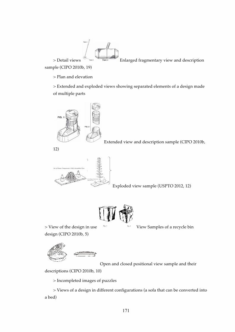
Extended and exploded view. All three interviewees stated that extended and
exploded views are not acceptable. Interviewee 2 defined such views as
“disassembled” [demonte] views; while Interviewee 3 stated that even if the article is
a complex product, it should not be visualised as extended or exploded, as each part
should be filed separately.
Interviewees 1 and 2 explained that a complete view of the assembled article should
be submitted within the visual representation. Interviewee 1 showed the first figure
in the example of USPTO (Figure 22) as an acceptable representation. Interviewee 3
indicated that examiners ask for a complete finished article rather than an extended
and exploded view, and added that some of the foreign design applications in
Turkey had such views and TPI examiners ask them to extract those views from the
Turkish national application.
Acceptable Unacceptable
Set of Game Components- Fully Assembled View
llyto
Set of Game Components-Exploded View
Figure 49 Exploded view sample of USPTO (USPTO 2012, 12), which are shown to
the TPI examiners. The fully assembled view on the left hand side is considered
acceptable and exploded view on the right hand side by the TPI examiners.
105
4.4.4.2.3 Repeating surface patterns
Interviewees 1 and 2 indicated that it does not matter if the applicant displays only
one portion a surface pattern or more than one portion repeated in the visual
representation in terms of the scope of protection.
Interviewee 3 gave the example of a carpet design, and indicated that applicants
usually file a picture of the whole carpet as a visual representation. He indicated
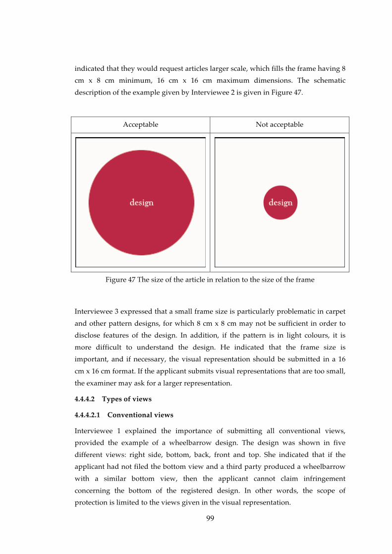
that if the views of the complete carpet design are submitted in 8 cm x 8 cm format,
the visibility of the details of the design will be obscured. For this reason, only the
portion which will be repeated through that design is convenient for representation,
and in large dimensions, which will also help to perceive the details of the design.
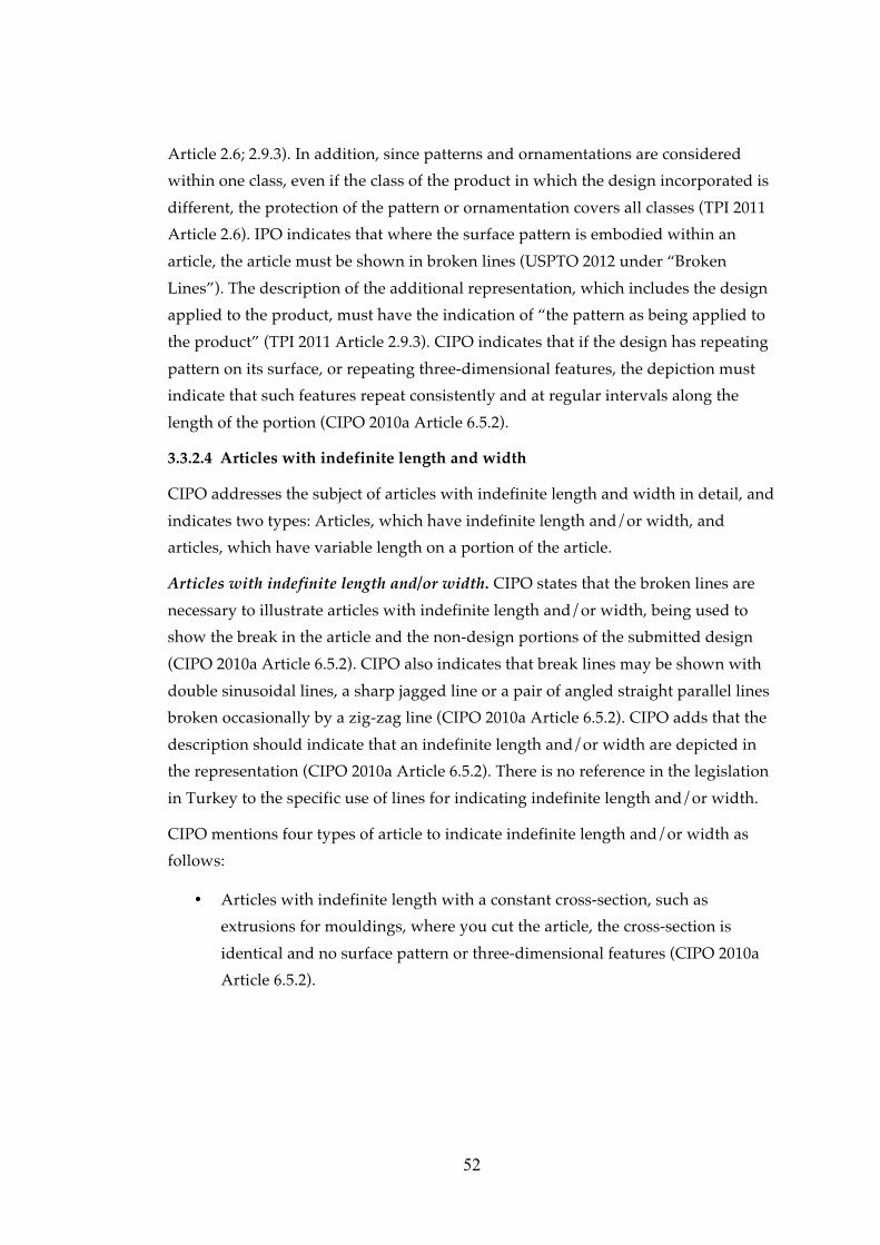
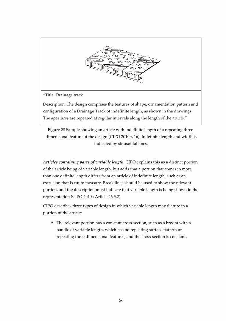
4.4.4.2.4 Articles with indefinite length and width
Interviewee 1 indicated that if the proportions of the design change due to a change
in size, an additional view of the same design will not suffice, and an additional
design application should be made. Interviewee 1 gave the example of a waiting
seat design for articles of indefinite length, stating that only one portion of the
article need to be submitted in the visual representation if the design repeats
consecutively. For another example, that of a profile design, she indicated that the
appearance would not change when the size changes. On the other hand, in a
vacuum cleaner design proportions may change as the size increases. In such cases,
she stated, another application should be filed for the changed version of the design.
Interviewee 3 also gave the example of profiles, and indicated that applicants
usually sought to protect the chambers within their profile designs. He stated that
even though visual representations are in three-dimensional format, protection is
sought for those chambers, meaning that cross-sectional views are very important in
profile designs. He added that in some cases the outer appearance of the profiles
may become more of an issue, for example in the case of a profile design having an
elliptical outside surface, in which case three-dimensional views are important.
Interviewee 2 cited a design of a fence as an example of an article of indefinite
length or width, and stated that only a portion of the repeated part is required in the
visual representation in terms of scope of protection.
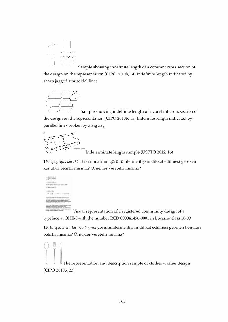
4.4.4.2.5 Typographic typeface designs
Interviewee 3 indicated that all characters must be shown in one view. Interviewee 1
stated she had only examined one typographic typeface design application, but
stated that she had asked for separate views of 8 cm x 8 cm for each character of the
106
typeface. On that occasion the applicant failed to remedy the formal deficiency, and
the application was deemed invalid. Interviewee 2 expressed she had not had the
opportunity to examine a typographic typeface design.
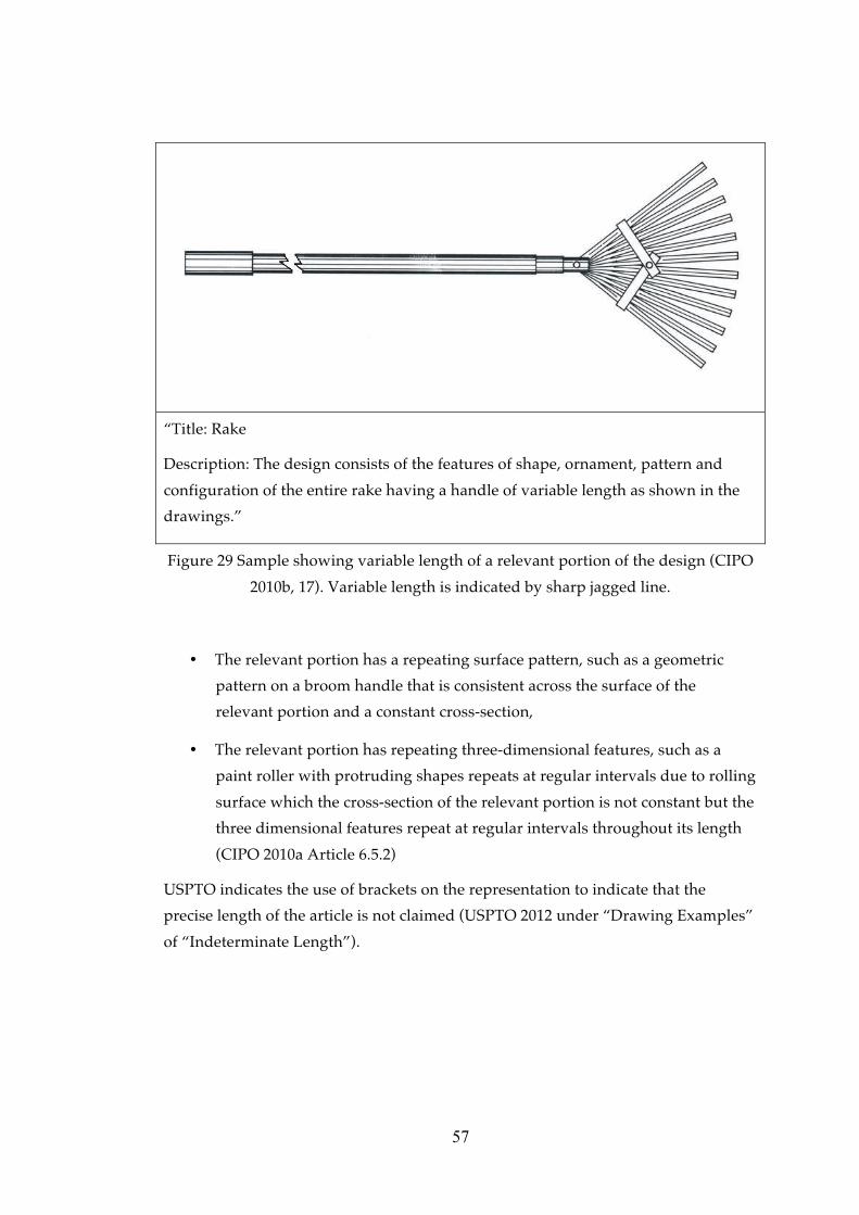
Registered Community Design No. 000041496-0001 of a typographic typeface,
which includes all letters of the alphabet, in both upper and lower cases, Arabic
numerals and punctuation marks displayed in one view as seen in Figure 31, was
shown to the interviewees. Interviewee 1 said that they may implement OHIM’s
practice in Turkey. Interviewee 2, on the other hand, stated that as it had been
encountered previously, she would define such a representation as a page layout
design rather than a typographic typeface design.
4.4.4.2.6 Designs comprising multiple components and complex products
Complex product. Interviewee 3 explained that each individual component of a
design can be protected individually if the design is of a complex product, and
added that if only the whole complex product is submitted within one application
without submitting each component as a separate design application, then the
complex product as a whole, not the components individually, shall be protected.
All of the interviewees indicated that if individual protection is sought for the
components of a complex product, visual representation of the whole complex
product should be filed as the first design, and each component for which
protection is sought should be filed as an additional design in one multiple design
application.
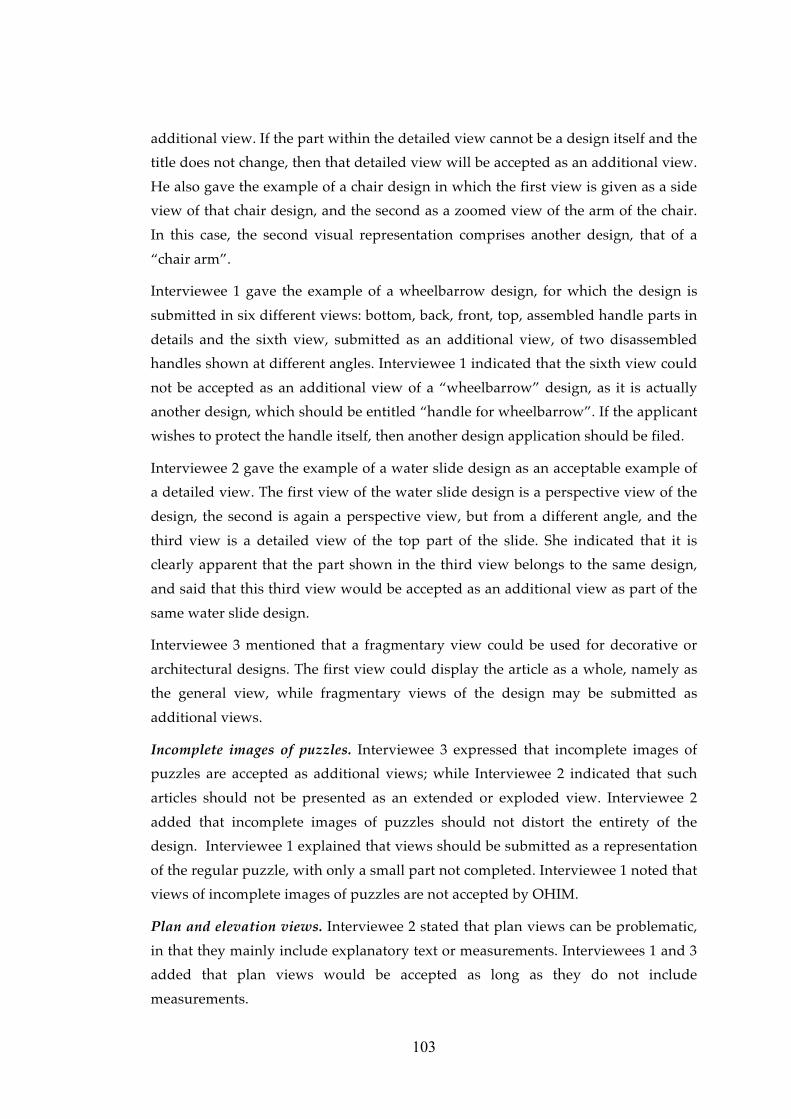
As an example of a complex product, Interviewee 1 gave the example of a vacuum
cleaner, which is accepted as one article in terms of design registration. She added
that a tea pot [çaydanlık] design also falls within the scope of the definition a
complex product design, being perceived as a combination of multiple objects.
Interviewee 1 gave the registration number of a multiple design application, TR
2011/07942, in order to show an acceptable example of a complex product’s visual
representation.
107
TR
2011/07942 Views of the designs
Design No: 1
Title: Vacuum
Cleaner
Design No: 2
Title: Part of a
vacuum
cleaner
Design No: 3
Title: Part of a
vacuum
cleaner
Design No: 4
Title: Part of a
vacuum
cleaner
Design No: 5
Title: Part of a
vacuum
cleaner
Design No: 6
Title: Part of a
vacuum
cleaner
Figure 50 Visual representations of a registered complex product design in Turkey
with the number TR 2011/07942
108
Figure 48 (Continued)
Design No: 7
Title: Part of a
vacuum
cleaner
Design No: 8
Title: Part of a
vacuum
cleaner
Design No: 9
Title: Part of a
vacuum
cleaner
Design No: 10
Title: Part of a
vacuum
cleaner
Design No: 11
Title: Part of a
vacuum
cleaner
Design No: 12
Title: Part of a
vacuum
cleaner
Design No: 13
Title: Part of a
vacuum
cleaner
109
Figure 48 (Continued)
Design No: 14
Title: Part of a
vacuum
cleaner
4.4.4.3 Ordering and numbering the views
Total number of views. Interviewee 3 put forward an application by a foreign
applicant as an acceptable example, which included six or seven different views.
However, he did mention that submitting three different views of the design might
have been sufficient.
Arrangement of views. Interviewee 1 indicated that applicants rarely pay enough
attention to the order of views, and complained that they often arrange the views
randomly in design applications.
All of the interviewees indicated that the perspective view should be submitted as
the first view. Interviewees 1 and 2 stated that the first view should be a perspective
view, which allows a clear understanding of the design and shows the general
features of the design to be protected. Interviewee 2 expressed that “submitting the
side view as 1.1” does not help with the legibility of the design. Side views and the
like should be submitted as additional views.
Interviewee 2 mentioned common deficiencies in the arrangement of views, and
gave the example of an application filed as one design registration application with
eleven views. However, during the examination of the visual representation, the
examiner found out that there were two different designs: First design having five,
and the second design having six different views. Such mistakes of arrangement of
the views not only cause remedy of the arrangement of visual representation, but
also they require remedies on descriptions of the designs.
Numbering and labelling the views. Interviewees 1 and 3 explained the two-digit
numbering system for design applications, with the first digit indicating the number
of the design, and the second indicating the number of the view of that design, i.e.
“1.1,” refers to the first view of the first design, and “1.3,” the third view of the first
design. Interviewee 3 indicated that the views labelled as 1.1, 1.2 and 1.3 as if they
are different views of the design may turn out to be the representations of three
110
different designs which should be labelled as 1.1, 2.1 and 3.1.
4.4.5 Partial disclaimer
4.4.5.1 Visual representation of partial disclaimer
All of the interviewees indicated that partial disclaimers should be indicated very
clearly on the visual representation, and suggested two alternative ways of doing
this by visual means:
• Showing the portion for which protection is claimed by adding a circle,
ellipse or square around it. Interviewee 3 suggested outlining the part for
which protection is sought with a red circle.
• Showing the non-design portions of the design in stippled or dotted lines.
Interviewee 3 underlined that dotted lines are only used for features of the
design for which no protection is claimed, with the features for which
protection is claimed shown in solid bold lines.
Interviewee 1 added that whichever method is selected, the partial disclaimer
should be clearly visible on the representation, even after scanning.
Interviewee 1 indicated that if there is a partial disclaimer for a design not shown in
the visual representation, it would be a ground for a formal deficiency. She gave the
example of a bottle lid. If the visual representation of the lid design is submitted
together with the bottle, without clearly indicating that it is the lid for which
protection is sought, the examiner shall ask for a partial disclaimer on the visual
representation. She added that a much more appropriate way for representing a lid
design would be to show the design individually from different angles, and
submitting a view of the lid on the bottle with a partial disclaimer as an additional
view.
Interviewee 1 indicated that sometimes a portion of the article is claimed to be
protected but it cannot be visualized separately. Interviewee 2 gave the example of a
spoon design, where the design to be protected is the ornamentation on the handle
part of the spoon. In this case the examiners would ask for a visual indication of the
parts of the article for which protection is claimed on the visual representation.
4.4.5.2 Verbal description of partial disclaimer
Interviewee 1 indicated that any partial disclaimer should be in combination with
the visual representation, the title of the design, and the description of the article.
Again using the lid design example, she suggested the title “the lid of a bottle”.
Interviewees 2 and 3 added that the description should not describe the entire
111
article but only the portion and its features for which protection is sought.
4.4.6 Format and quality of visual representation
Interviewee 3 indicated that the resolution of the image submitted as representation
is the most common problem related to the format and quality of visual
representations.
4.4.6.1 Physical quality
All of the interviewees claimed that the scanning procedure at TPI is a problem in
terms of the loss of resolution of the image when dealing with paper submission
applications. Interviewee 2 explained that all visual representations submitted with
paper applications are scanned at TPI and uploaded onto the system. Interviewees 1
and 2 indicated that if the submitted visual representation is only medium
resolution, the resolution after scanning gets even worse. Both interviewees
indicated an approximately 10% loss of image clarity due to scanning; and during
publication there will be a further loss of resolution. Interviewee 1 added that
scanning also causes a loss of colour in the visual representation. In particular, if the
article being represented is black, details of the design will disappear after scanning.
Interviewee 2 stated that it is better to submit visual representations in digital
format as well when filing a paper submission application. She said that some of the
examiners’ computers do not have DVD readers, and therefore soft copies of visual
representations should be submitted in CD rather than DVD format.
Interviewee 1 indicated that they had once received an application on which the
visual representations were pasted with glue. After a while, they observed that after
the glue had dried, the visual representations had become totally invisible.
Size and quality of paper. Interviewees 2 and 3 indicated that applicants should not
submit visual representations on the application form, but rather printed on a
separate sheet of A4 paper, otherwise a formal deficiency may be given by the
examiners.
Only Interviewee 1 indicated that some applications were not submitted on A4
white paper. She mentioned that the problem is rare, but stated that one time they
had received an application form with visual representations printed on low-quality
newsprint paper. On another occasion, she encountered an application in which the
visual representations were submitted on scrap paper.
4.4.6.2 Data format for e-filing
All of the interviewees stated that applicants who file their applications
112
electronically commonly make errors in the ordering and numbering of visual
representations. For example, while assessing a design application of one design
with eleven views, during formal examination it emerged that there were actually
two different designs with five and six views each.
Interviewee 1 indicated that they did not encounter problems of resolution in the
visual representations of electronically filed applications; however, Interviewee 3
stated that in electronically submitted visual representations, problems of size and
clarity may be encountered.
Interviewee 2 stated that uploading the visual representation of an electronically
filed application on to the data system is easier than scanning and uploading the
representation of an application submitted on paper.
4.4.7 Unacceptable visual representations
Interviewee 2 indicated that only visual representations that are contrary to the
principles of public order and general morality are provisionally refused.
Interviewees 2 and 3 expressed that an application will be refused if it does not
confirm with the definitions of “design” and “product” given in the Decree Law
Article 3(a) and (b) during the formal examination. Interviewee 2 added that if the
visual representation displays an article, which is accepted as “design” but has
formal deficiencies, then the examiner would request the formal deficiencies to be
remedied for granting the application date. Interviewee 2 said that if the formal
deficiency is not remedied within the time period stated in the Implementing
Regulation, then the application shall be deemed invalid.
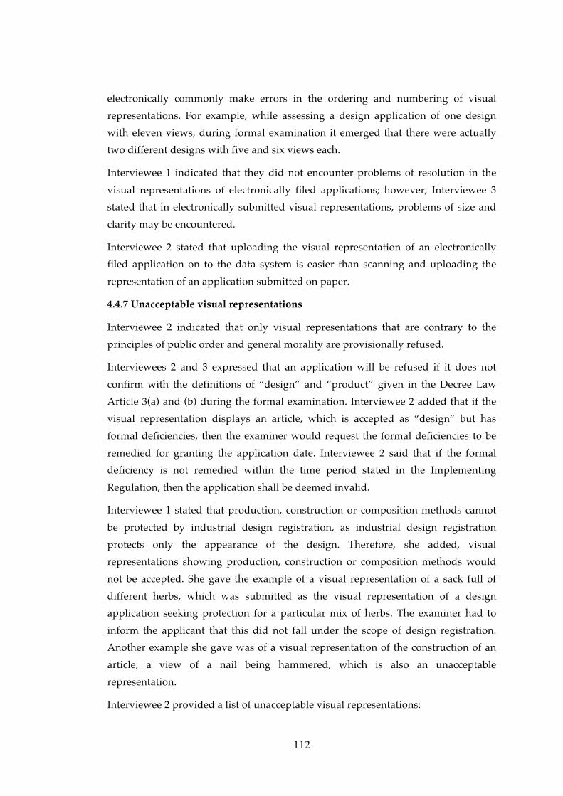
Interviewee 1 stated that production, construction or composition methods cannot
be protected by industrial design registration, as industrial design registration
protects only the appearance of the design. Therefore, she added, visual
representations showing production, construction or composition methods would
not be accepted. She gave the example of a visual representation of a sack full of
different herbs, which was submitted as the visual representation of a design
application seeking protection for a particular mix of herbs. The examiner had to
inform the applicant that this did not fall under the scope of design registration.
Another example she gave was of a visual representation of the construction of an
article, a view of a nail being hammered, which is also an unacceptable
representation.
Interviewee 2 provided a list of unacceptable visual representations:
113
• Unclear views,
• Visual representations containing numbers, explanatory text or descriptions
of the design,
• Designs which cannot be perceived clearly due to problems in the use of
colour in figure-background relationship.
Interviewee 3 provided the following list of unacceptable features in visual
representations:
• Lack of clarity which is the most important one,
• Visual features of the design that are not clearly shown,
• Background and article are in the same colour,
• More than one view in one visual representation.
As mentioned before, all of the interviewees stated that extended and exploded
views are unacceptable.
4.5 Further comments and suggestions by the TPI experts
Interviewee 1 recommended that visual representations should be bright, in large
dimensions, sufficiently clear, and should include the views of the design from
different angles. She added that the description of the design is also important.
Interviewee 1 gave an example of a bowl design, for which, the applicant claimed,
the distinctive part of the design was the four “ticks” on the bottom of the bowl. The
applicant defined the way his/her design differs from other bowl designs on the
market by indicating that in the description.
Interviewee 3 said that applicants should give more weight and importance to the
visual representations.
Interviewee 1 suggested that applicants and attorneys attach more importance to
their duty. Interviewee 1 expressed that the power of attorney or application fee
might be missing, however, the visual representation should not be, as it constitutes
the most important part of a design registration application. Interviewee 2
suggested to both attorneys and applicants that:
• They should carefully read the information published by TPI on how design
registration applications are made, and
• They should call the examiners directly if they want more specific
information about their application.
Interviewees 1 and 2 advised attorneys working in the design registration field to
explain the importance of submitting additional views and the clarity of the visual
114
representations to their clients, which will help in achieving acceptable visual
representations. Interviewee 3 indicated that the international applications through
the Hague System and applications with priority of foreign registrations or
applications usually submitted adequate visual representations. He suggested
attorneys to use drawing software for preparing visual representations of design.
Interviewee 2 stated that the reason for deficiencies is generally related to the
knowledge level of the applicant when no attorney has been assigned.
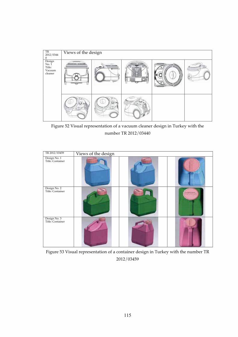
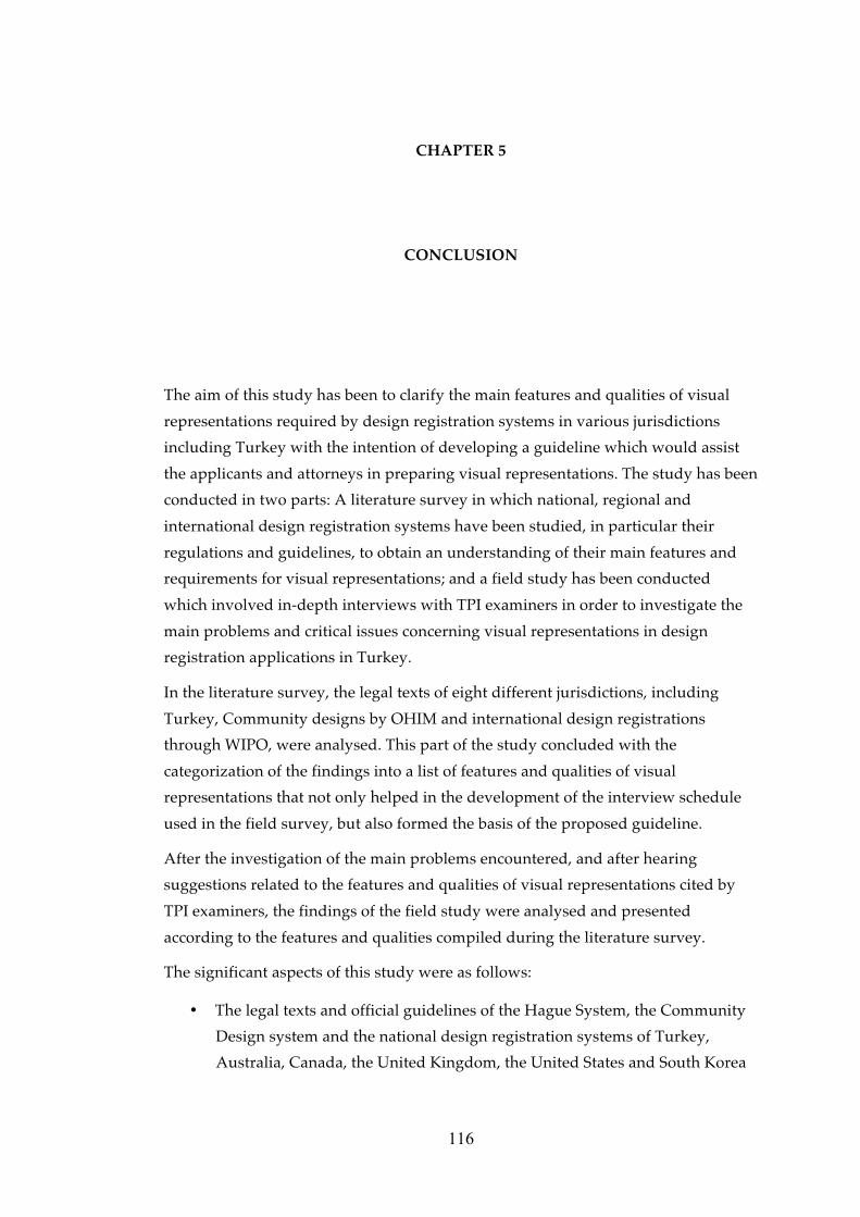
Interviewee 3 gave three design registration applications as “acceptable visual
representation examples” during the interview. The visual representations of those
applications are given in Figure 51, 52 and 53 together with their application
numbers.
TR 2012/00059
Views of the design
Design No. 1 Title: Turnable mob
Design No. 2 Title: Turnable mob
Design No. 3 Title: Turnable mob
Design No. 4 Title: Turnable mob
Figure 51 Visual representation of a turnable mob design in Turkey with the
number TR 2012/00059
115
TR 2012/03440
Views of the design
Design No. 1 Title: Vacuum cleaner
Figure 52 Visual representation of a vacuum cleaner design in Turkey with the
number TR 2012/03440
TR 2012/03459 Views of the design Design No. 1 Title: Container
Design No. 2 Title: Container
Design No. 3 Title: Container
Figure 53 Visual representation of a container design in Turkey with the number TR
2012/03459
116
CHAPTER 5
CONCLUSION
The aim of this study has been to clarify the main features and qualities of visual
representations required by design registration systems in various jurisdictions
including Turkey with the intention of developing a guideline which would assist
the applicants and attorneys in preparing visual representations. The study has been
conducted in two parts: A literature survey in which national, regional and
international design registration systems have been studied, in particular their
regulations and guidelines, to obtain an understanding of their main features and
requirements for visual representations; and a field study has been conducted
which involved in-depth interviews with TPI examiners in order to investigate the
main problems and critical issues concerning visual representations in design
registration applications in Turkey.
In the literature survey, the legal texts of eight different jurisdictions, including
Turkey, Community designs by OHIM and international design registrations
through WIPO, were analysed. This part of the study concluded with the
categorization of the findings into a list of features and qualities of visual
representations that not only helped in the development of the interview schedule
used in the field survey, but also formed the basis of the proposed guideline.
After the investigation of the main problems encountered, and after hearing
suggestions related to the features and qualities of visual representations cited by
TPI examiners, the findings of the field study were analysed and presented
according to the features and qualities compiled during the literature survey.
The significant aspects of this study were as follows:
• The legal texts and official guidelines of the Hague System, the Community
Design system and the national design registration systems of Turkey,
Australia, Canada, the United Kingdom, the United States and South Korea
117
have been analysed in terms of the features and qualities of visual
representations.
• These features and qualities related to visual representations have been
studied together with the problems encountered by TPI examiners.
• The study also highlighted the suggestions of TPI examiners to applicants
and attorneys concerning visual representations in design registration
applications.
The limitations of the study were as follows:
• The legal texts and official guidelines in eight jurisdictions only were
reviewed due to time and language restrictions.
• The examples of unacceptable visual representations revealed in the field
study were not presented within this thesis as those design applications are
still pending and have not been published, yet. In order not to prejudice the
novelty and distinctive character of those designs, only verbal or schematic
descriptions of their visual representations were presented.
5.1 Proposed guideline for visual representation
A general overview of the topics and sub-topics of the proposed guideline is given
in Figure 54, and the proposed content of the topics and sub-topics is covered in the
following sections.
Figu
re 5
4 T
he to
pic
s an
d s
ub-
top
ics
conc
erni
ng th
e fe
atu
res
and
qu
alit
ies
of v
isu
al r
epre
sent
atio
n
base
d o
n bo
th th
e lit
erat
ure
rev
iew
and
the
fiel
d s
urv
ey fi
ndin
gs
�����������
�� �����
������� ���
���������
�������������
��������
� ���������
�������
��� �����������
!����������
������
" ��������� ��
" #��$
��������� ��
" ���� �����
��� ���
� �������
" ��������� ����
����%������
������� ���
�����
" !�������
�����������
���������
�����������
���������&�
���������
'�������� ���
���(������
� ��� ��
����� �����
���� ��
��������� �����
���( ��
������������
)��� �� ���
*� �����
������ ��
*� �����
! � ���� ��
����$%������
+� ����� (���
����
������ (���
�& ������
)�������
��������� ���
������������
118
119
5.1.1 Types of visual representation
Visual representation of designs can be submitted in three forms: Graphic
representation, which includes drawings and ink drawings in particular,
photograph and specimen. Visual representations can be submitted in black and
white or in colour, so long as they are suitable for reproduction by publishing.
5.1.1.1 Graphic representations
Graphic representations of a design can be prepared by using drafting instruments,
or executed by electronic means to a professional standard. Either way, the graphic
representations should:
• Be explicit and clear,
• Be of good quality, either the original drawing, or better still, good quality
scans or copies,
• Have satisfactory reproduction characteristics, such as visible solid black
lines,
• Have all edges cut at right angles,
• Be prepared in such a way that the article is shown on a neutral, plain
background.
It is recommended to use drawing software in the preparation of visual
representations.
Graphic representations that include explanatory text or measurement indications
are unacceptable.
Types of line drawings. There are two types of drawings: Ink drawings, which refer
to line drawings or black and white drawings; and coloured drawings. It is up to the
applicant to select the most practical type for depicting the design clearly. It is
suggested that plain black and white drawings be used if the scope of protection
does not cover a particular colour.
Quality of lines. The lines of the drawings should be durable, clean, solid,
sufficiently dense and dark, uniformly thick and well-defined.
The lines should be solid and the weight of the lines, including lines representing
shading or cut surfaces of cross-sectional views, must be heavy enough for
reproduction through publishing or scanning.
Lines or strokes in different thicknesses may be used to denote different elements,
i.e. bold lines for the outline of the design to be protected. In such cases it is
120
important that all lines stay visible after reproduction through publishing or
scanning.
Broken lines, dotted lines or stippled lines. Dotted lines can be used either to show
the features or parts for which protection is not being sought (partial disclaimer), or
to indicate parts that are not visible in that particular view. It is suggested for three-
dimensional designs, not to show the lines of the features, which cannot be seen on
that particular view of the article on the drawing. Dotted lines should not be used
to indicate elements that are not part of the design to be protected, while solid lines
should be used to show the features for which protection is being sought. It is
suggested not to use the broken lines for showing hidden planes and surfaces that
cannot be seen through an opaque material of the article due to possibility of
preventing an explicit understanding of the design.
Broken lines can also be used to show environmental structures17 that are not part
of the design. If broken lines are used in this way, they should not intrude upon or
cross the claimed design, prohibiting a clear understanding of the design.
Another use of broken lines is the boundaries that form the non-design parts of the
article for which protection is claimed.
Showing alternate positions of the design using full and broken lines on the same
view is prohibited.
Broken lines should be lighter than solid lines which indicate the design features to
be protected, however all lines should be heavy enough to be visible after
reproduction through publishing or scanning.
Shading. Embossed parts of the design can be shown through shading or in the
form of parallel lines. Shading can also be used for providing relief. Shading can be
used to illustrate the shape of the design, in particular, any spherical, cylindrical or
conical elements of an article. Additionally, shading is used to distinguish the open
and closed solid areas of the article. Another use of shading may indicate a contrast
of tones in the design, which is shown in Figure 3. On the other hand, the character
and contour of all surfaces of any three-dimensional aspects of the design can be
represented by shading.
There are two styles of shading accepted by USPTO: Straight-line surface shading
and stippling; the sample representations are given in Figure 5, 6 and 7. A
17 The environmental structure should not be disclosed unless it is necessary to show the environmental structure and the design together in a representation for a better understanding.
121
combination of both styles on the same article can be used to show surface contrast
in Turkey, however such a combination on the same surface should not be used
because it may distort the understanding of the design.
Shading should not distort or hide the design to be protected and should be
consistent in all views. If non-design portions are illustrated using stippled lines,
then shading should not be used on those sections.
Solid black surface shading should not be used, as it may hide features of the
design. Black shading should only be used in cases where protection of the colour
black is part of a design for which protection is sought.
Flat parts need to be lightly shaded. If possible, shading should be indicated by
spaced and lighter lines, lighter than those used in the rest of the drawing, so as not
to distort the understanding of the contour of the design to be protected. The angle
of the shading lines could be 45 degrees, coming from the upper left corner.
Transparency and translucency. Transparency may be illustrated by using thin lines
of shading, as shown in Figure 9. It should not be shown using stippled lines,
especially in cases where non-design portions of the design are also illustrated using
stippled lines. Transparent surfaces should be shown using light and full lines
rather than stippled or broken lines.
Translucency can also be indicated by using thin shading lines and an overall
shading of the translucent area; the sample representation is given in Figure 10.
Additionally, elements behind transparent parts of the design should be illustrated
using light but full lines rather than broken lines as shown in Figure 11.
Hatching. Hatching can be used to provide relief. Another use of hatching is in cross
sectional views, which is explained within section 5.1.3.2.2 Non-conventional views.
5.1.1.2 Photograph
Photographs must be to a professional standard and of high quality, preferably
taken by a professional camera. They should be explicit and clear, not blurred.
Black and white photography serves as well as coloured photography, unless the
particular colour of the design is not intended to be protected as a design feature.
Black and white photography, in other words, images in grey scale, should not
result in a loss of clarity of the details of the design.
Photography should be of sufficient quality to ensure that all the details of the
design are visible during or after reproduction by printing or scanning,.
122
The article should be presented in front of a natural, plain and clear background,
which should be in a contrasting colour to the article so as to allow a clear
understanding of the design. For example, black articles should not be
photographed in front of a black background. For further explanations on article
and background configurations, please see section 5.1.2.
Photographic representations must not be retouched using ink or correction fluid.
Photographs should include no items other than the design itself, including the
environmental structure if it is not necessary for a clear understanding.
Using a spotlight may impede visibility and affect the legibility of the design and its
features. Confusing highlights, reflections and heavy shadows should be avoided.
If the article is made of transparent or shiny materials, then a graphic representation
rather than photography may permit a clearer definition of its features.
During photographing, if the camera is too close to the article it may cause
distortion and prevent a clear understanding of the design.
5.1.1.3 Specimen18
A specimen rather than printed visual representations may be submitted if it is not
possible to submit a visual representation of a two-dimensional design and a
deferment of publication is requested.
5.1.2 Content of the visual representation
The content of the representation of the design must be explicit, clear, definite and
complete. All of the special characteristics, in other words, the features of the design
to be protected, should be shown clearly. The representation should be suitable for
reproduction by publication or scanning.
The submitted representations of the design should raise no doubts or
misunderstandings about the design or the features sought for protection. Nothing
regarding the design to be protected should be left to conjecture.
The representation should contain no other representation, part of any other
representation, numbering, measurement indications or explanatory text.
5.1.2.1 Article
The article should be shown in complete isolation, containing no non-design
elements. For example, visual representations of a tribune design should not include
18 Requirements concerning specimens fall outside the scope of this thesis, and so are not included within the proposed guideline.
123
anything that is not part of the design, such as buildings, trees, towel left beside the
tribune, etc.
In some cases a view that shows the environment and the design together may be
acceptable, so long as the environment helps provide a better understanding of the
design. The environment may be illustrated in stippled lines in order to indicate that
it is a non-design part and is not being claimed for protection. The drawings, the
description and the title of the design must be in combination and indicate clearly
the design features. It is important to indicate clearly the differentiation between the
finished article to which the design is applied and the environment on the visual
representation. In cases where the application is filed with a view showing the
environment and the design together, it is recommended that the application
contain also views of the article in complete isolation.
The article should be shown completely, as a whole, on the visual representation
frame without cropping.
Care should be taken when photographing articles that are either very light or dark
colour to ensure the details of the design to be protected are clearly visible. Light or
dark coloured articles may impede visibility and prevent the clear understanding of
the details of the design.
Articles made of transparent or shiny materials, such as glass, may also be
unsuitable for representation with photography. As mentioned in section 5.1.1.2, it
is more convenient to submit a graphic representation of such designs, which are
made of such kinds of transparent of shiny material for disclosing all the details.
If the proportions of the article do not change with changes in the size of the design,
then there is no need to file an additional design application for a different size of
the same article. However, if the design proportions do change, then an additional
design application should be filed for each design, for example, two mugs of similar
design with identical handles but with different sized main container sections. In
this case an additional design application should be filed for the second design, in
that the proportions have changed, affecting the appearance.
5.1.2.2 Background
The background should be simple, plain, smooth and neutral. There should be no
non-design elements on the background of the visual representation.
Additionally, the background should be in a contrasting colour to the article. For
example, using a black background for a black article may limit the understanding
124
of the features of the design and may result in the application receiving a formal
deficiency. Using a light-coloured background for articles made of transparent
materials may also reduce the legibility of the details of the design to be protected.
5.1.2.3 Colour
There are two types of representations in terms of colours: monochrome (black and
white) and colour.
Monochrome representations can be used where no protection is claimed for the
colour of the design. If the applicant wishes to protect only the shape of the design
without defining a particular colour, then black and white drawings are
recommended. When a visual representation is submitted in colour, the scope of
protection covers the design also in different colours. The design in different colours
can be accepted as additional views, but not as additional designs.
Colour may be accepted as distinctive in ornamental or pattern designs, graphic
designs or logos, as the harmony between colours may give individual character to
the design to be protected. In such cases, if the colour is a part of the design,
representations should be filed in colour.
5.1.3 Views of design
Additional views, in other words additional visual representations, are images of
the same design from different perspectives.
At the application stage, the formal examination includes an assessment of whether
the design is shown entirely and clearly in the visual representations and additional
views. Representing the design from different angles is very important after the
registration stage, when the assessment of the novelty and individual character or
an infringement analysis is conducted, based on the visual representations of the
design. For this reason, the submitted views of the design must be as clear as others
and must reflect all aspects of the design and allow a clear and explicit
understanding of the design and its features. Submitting different views of the same
design is also important for illustrating all of the characteristic features of the
design.
If the applicant wants to obtain a maximum protection through the registration,
then the design should be fully represented. The applicant should ensure that the
design is fully represented because only aspects of the design that are visible in the
visual representations shall be protected. Accordingly, the visual representation
should consist a series of views form different angles in order to show the overall
125
appearance of the design, especially where the design is three-dimensional. . Hence,
there should be a sufficient number of different views to avoid any doubt of exactly
what the applicant is requesting to be registered. It is recommended that three-
dimensional articles should be represented in at least three views, one of which
should a perspective view showing the three sides of the article.
Once the application has been filed at the Office, the submission of additional views
is prohibited. For this reason, views should be prepared and selected carefully
before submitting an application.
All views should be filed separately. In other words, the visual representations
should not include more than one view within one representation, and each view
should be submitted on a separate visual representation frame. Views of the design
from different angles within one representation will not be accepted, even if the
views are explicit and clear.
Additional views of the design should not disturb the integrity or unity of the
design, and all views must belong to the same design for which protection is being
sought. Individual or dissembled views of the parts of the design will not be
accepted as additional views. For example, in the case of a wheelbarrow design
application, views of two disassembled handles of the wheelbarrow submitted as an
additional view cannot be accepted as an additional view of a wheelbarrow design.
The representation does not contain the wheelbarrow, only the handles, and if
protection is sought specifically for the handles, it must be filed as an additional
design under the title “handles of a wheelbarrow”. If the appearance of the design
differs from the other views and the title changes, then that view should be filed as
an additional design rather than as an additional view.
All the views must be designated properly, such as perspective view, front view,
side view, etc. and describe from which angle the article is disclosed can be added to
the description of that particular view.
Additional views, the description and the title of the design should be in unity. The
description of the additional view should describe the visual properties of that view,
and all views should be designated properly.
A view may be accepted as additional design if the visual features change, even if
the title and the design itself stay the same. For example, a bicycle design for
multiple riders. The first view of that design is the completed version of the design
in which all of the component parts are assembled, including seats, shades, tyres,
etc., while the second view shows only the main structure of the same article
126
without the external parts. Even though the title and the article are the same in both
views, the second view cannot be accepted as an additional view of the first design
because the appearance of the article is different. In such cases, where the overall
appearance differs, the views should be filed as additional designs, not additional
views.
5.1.3.1 Dimensions of views
Visual representations should be submitted minimum 8 cm by 8cm and maximum
16 cm by 16 cm. Representations cannot exceed 16 cm by 16 cm. All representations
must be presented as a whole, and must be submitted in the form of right-angled
quadrilaterals (squares and rectangles), with their edges cut at right angles.
The representation of the article should be positioned in the representation frame in
large scale. In other words, the image of the article should fill the frame of the
above-mentioned dimensions. Schematic description of the size of the article in
relation to the size of the visual representation frame is given in Figure 47.
The selected size of frame should suitable for showing all details of the design
clearly. If the size of the representation is large, then the visual features and the
details of the design can be understood clearly. In particular, articles with intricate
details, such as toothbrush designs or carpet patterns, or articles that are large, such
as cars, bikes, buildings, etc., should be filed in the maximum dimensions.
5.1.3.2 Types of view
There are two main types of views: conventional and non-conventional. In addition
to these, there are other types of views suitable for other situations, such as
repeating surface patterns, articles of indefinite length and width, typographic
typeface designs, etc., which are also explained within this section.
5.1.3.2.1 Conventional views
Conventional views are perspective, front, back, top, bottom, right and left side
views.
A perspective view is the best option for showing the product from all three
dimensions, and can reveal important details of the design on a single view. It is
recommended that one of the views should be a perspective view for three-
dimensional designs because of three different sides of the same article can be
displayed in one view. It also helps better understanding of the design if all the
surfaces are clearly understood and fully disclosed in a perspective view.
127
Unless all the surfaces are fully represented and the details of the design reflected
clearly in the perspective view, additional views will be necessary to ensure a clear
understanding of the overall appearance of the design.
The scope of protection is limited to the views given as visual representations of the
design. If one of the views is missing, such as a bottom view of a three-dimensional
design, then the applicant cannot claim an infringement concerning the bottom of
his/her registered design against a similar bottom design of a third party’s product.
If the two sides of the design to be protected are exactly same, a statement
indicating as such can be filed within the description.
5.1.3.2.2 Non-conventional views
Non-conventional views are views that display features of the article that cannot be
seen from conventional views, and include cross-sectional views, views showing the
design in use, detailed views, incomplete images of puzzles, plan and elevation
views, and extended and exploded views.
Sectional, cross-sectional or cut-through views. Since the design registration
protects only the external appearance of articles in their normal use, cross-sectional
views can be used to show any exterior features of the design. Cross-sectional views
should be used if it is necessary to display a particular aspect of an external shape of
the design, which may not otherwise be clear in a two-dimensional drawing. It
should not show internal features of the design that cannot be seen during the
normal use of the article. It is important for cross-sectional views to display features
of the article that are visible when the article in use. In such cases, using cross-
sectional views also helps provide a better understanding of the design and
minimizes the number of views required.
Cross-sectional views must not show functional features or any interior structure
that does not form a part of that claimed design. For example, a cross-sectional view
of a foodstuff design, which shows the inner layout of the food used in it, cannot be
accepted, as the registration system protects only the appearance of the design, not
the inner layout.
All materials of the article in a cross sectional view can be shown on a drawing by
using hatching method. Hatching can be used to denote different materials used in
the design in a cross-sectional view, which are to be regularly spaced, parallel and
oblique, and the space between strokes should be chosen to suit the total area to be
hatched. Hatching lines should be sufficiently spaced to enable the lines of the
design to be easily distinguishable. Different types of hatching should have different
128
meanings to denote the different materials seen in a cross-sectional view. Different
elements must be hatched at different angles.
Cross-sectional views cannot be accepted individually, and should be filed as an
additional view to a view that displays the external appearances of the design. As
seen in Figure 48, the first visual representation of the design can be a perspective
view, while the cross-sectional view can be submitted as a second (additional) view
of the design.
Showing the design in use. Views reflecting the utilizing features of the design are
accepted as additional views by TPI. Such views can be used for designs that
become clearer and more meaningful when shown in practical use. For example,
showing open or closed positions or extended or retracted positions of articles may
help to reveal the design features and clear understanding.
For views showing the article in open and closed positions to be accepted, the article
should have a physical connection while in both positions as shown in Figure 16.
For example, for a design of a container, if the body and lid are connected when the
container is open, then a representation of the open position of the article can be
accepted as a view showing the design in an alternative position. However, if there
is no physical connection between the lid and the body, then the lid in an open
position will constitute two designs, a body of a container and a lid of a container,
which should have different design titles and different Locarno sub-classes. Such
views are unacceptable, and can be perceived as extended or exploded views, which
are also not accepted by the TPI.
If a movable part of the article needs to be shown when in normal use, it should be
shown in a sequence of views, illustrated at the same angle, so as to reveal the
appearance of the product in different phases of its operation, cycle or use. Such
views should be indicated within the description of the view. For example, a
perspective view showing the design in use in a different position can be worded as
“perspective view in first alternative position".
Positional views of the design should not be illustrated using full or broken lines on
the same view. An example of an alternative positional view is given in 17.
Extended or retracted positional views of the design are acceptable if the article is
normally seen and used in those positions. An example is given in Figure 18.
The appearance of flexible flat articles may differ when laid flat or when in use, such
as such as clothing or cushion designs. Such articles may be demonstrated in both
positions: Laid and in use. An example is given Figure 19.
129
Detailed, fragmentary, enlarged of partial view. A detailed or partial view is used
to display part or parts of the design in detail to allow the understanding of the
details for which protection is sought. A detailed view should focus and enlarge
part of the article of which the design is applied in order to show the part in detail.
Fragmentary views are acceptable so long as they show a portion of the design in a
larger scale to better display of the details of the design.
An enlarged view or partial view can also be used considered as detailed view in
terms of using such views for the purpose of to magnification a portion of the
design.
A view of the whole design should be submitted together with any detailed,
fragmented, enlarged or partial view. Such view should be submitted on separate
visual representation frames and should be numbered separately. For example, a
perspective view of the design as a whole as representation may be numbered 1.1,
and the detailed view of the design may be numbered 1.2. The relationship between
the whole design and the detailed view should be clear and unambiguous.
If individual protection is sought for a part of a design shown on a detailed image,
then it must be submitted as an additional design, not as an additional view. For
example, if the applicant files an enlarged view of the handle of a chair as an
additional view to a chair design, the handle will not be protected individually. If a
third party produces a chair with a same handle but different body part, then the
owner cannot claim an infringement for the handle of that design as only the overall
impression of a registered design falls under the scope of protection. Therefore, if
the applicant desires to protect the part of the design shown in the detailed view
individually, being the handle of the chair in this example, another design
application needs to be filed, rather than submitting that view as an additional
detailed view to the design views as a whole.
Detailed views should not distract from the integrity and unity of the design to be
registered, as they may be problematic if the part within the detailed view can be
subject to another design registration. Examiners may not accept the detailed view
of a design if the part within that representation cannot be described as an
individual “design” and the title of that view changes. In the case of the chair and
handle example, the handle can be subject to another design application, and the
representation showing the handle of the chair can be entitled “handle of a chair”.
Detailed views should not display dissembled parts of the design.
130
It should be clearly understood that a detailed view filed as an additional view is
part of the same design.
Incomplete images of puzzles. Such views should be submitted displaying the
regular puzzle with only a small part not completed, and must be filed as an
additional view along to a completed view of the design.
Views of the incomplete puzzle should not distort the integrity of the design, and
the article should not be shown in an extended or exploded view.
Plan and elevation views. Two-dimensional plan views should be free from
measurements or explanatory text. They should be legible and clearly display the
design features. If such a view is not legible or clear, then the examiner may ask for
a three-dimensional view of the design.
Extended or exploded views. Extended or exploded views of multi-component
articles, known as “dissembled views,” are not acceptable as shown in the extracted
views marked as “FIG: 2” at Figure 21 and exploded view marked as “Set of Game
Components- Exploded view” in Figure 22. The article should be shown fully
assembled in the visual representation. Even if the article is a complex product, it
should not be illustrated in an extended or exploded view; rather, each part should
be displayed and filed separately.
5.1.3.2.3 Repeating surface patterns
Patterns and ornamental designs are used for purposes of decoration, and can be
applied to the surface of various types of products without affecting their three-
dimensional forms or lines. Visual representations should show the complete
pattern and a sufficient portion of the repeating surface. The complete pattern
should be surrounded by enough of the repeated pattern to show how the pattern
repeats.
It is important to show the details of ornamentation or pattern designs, and
therefore filing an ornament or pattern design as a whole in an 8 cm by 8 cm frame
may not be sufficient for displaying the small details. For this reason, the repeated
portion and a sufficient portion of the repeating surrounding surface on a large scale
may provide a better understating and a good perception of the details of the
pattern.
A pattern design applied to a product may be accepted as an additional view of the
same pattern design, and should be filed as an additional view. If the surface
131
pattern is applied to an article, the article may be shown in broken lines to indicate
protection is sought for only the pattern design.
If the design is shown on a product, the description should state clearly “the pattern
as applied to a product”. The description may also indicate that the features repeat
consistently and at regular intervals along the length or width of the item.
Since pattern and ornamentation designs are considered in one Locarno class, even
if the class of the product onto which the design is incorporated is different, the
scope of protection of the pattern or ornamentation design covers all classes.
5.1.3.2.4 Articles with indefinite length and width
Different types of articles with indefinite length and width are explained below.
• Articles with indefinite length with a constant cross-section, such as
extrusions for mouldings, are can be defined as the articles that, when you
cut, the cross-section is identical and do not comprise surface pattern or
three-dimensional features.
• Articles with indefinite length with a repeating surface pattern, such as an
ornamented ribbon design, in which the repeating pattern is located on the
surface of the article, which does not affect the article’s width.
• Articles of indefinite length and width with a repeating surface pattern, such
as fabric with a repeating pattern. Both the indefinite length and width may
be shown with a stippled line around the pattern to be repeated which the
article’s section is constant and the sectional view is not affected.
• Articles of indefinite length with repeating three-dimensional features, such
as a drainage track with repeating apertures, where the cross-section is not
constant, yet the three-dimensional features are repeated at regular intervals
along the article’s length.
It is important to note that if the proportions of the article change with changes in
length and/or width, then the appearance of the product changes. Accordingly,
additional design applications should be filed for each different design.
Illustrating a portion of the repeated part of the article can be sufficient if the pattern
repeats consecutively and the appearance does not change with repetition, i.e. a
profile design for a sliding door or a fence design. The length of the article is
variable but repeats consecutively, but the appearance does not change.
Descriptions of such designs may indicate the features that are repeated consistently
and at what intervals along the length or width of the portion.
132
5.1.3.2.5 Typographic typeface designs
Visual representations of typographic typeface designs should show at least four
lines of text comprising all typographic characters in such a way that all the features
of each character can be clearly be seen. All characters should be shown, meaning all
letters of the alphabet in both upper and lower cases, a line of Arabic numerals and
five lines of text produced using the typeface, including both letters and numerals at
the minimum size of 16 Point as given in Figure 31.
On the other hand, single colour shall not assist ordinary typographic typeface or
graphic symbol design as a feature to be protected, if the design does not pass the
novelty and individual character criteria.
5.1.3.2.6 Designs comprising multiple components and complex products
Each component of a multiple component design can be filed as additional designs
within one design application if:
• the components forming the design have the same the visual properties that
can be seen during normal use, and
• the indication of the product in which the main design is classified should be
the same.
This is to prevent the component designs from being perceived as different designs,
in other words, multiple design applications rather than a design with multiple
components. For example, the representation of a pen with its cover or without its
cover may be accepted as additional visual representations; however, an individual
representation of the cover itself is considered as a different design, not as an
additional representation.
Get-up designs. Get-up designs are designs in which more than one product or set
of items that constitute a composition by them and can be perceived as one design,
such as trade dress, in-store layouts, indoor or outdoor designs, layouts. Such
designs need to be filed with multiple views, one of which should be a top view, in
order to display the layout of the design clearly. The description of the views should
not indicate all of the individual features of the products comprising the design, but
should reflect the ambiance of the overall appearance of the components and state
precisely for what protection is being claimed.
Designs comprising a set of articles. Such designs made up of a combination of
features should show clearly which elements are being claimed for protection such
as he articles of the set are so closely related that they can be considered as forming
133
a single product, i.e. spoons and knives as shown in Figure 32. At least one of the
views should show the set of articles together.
All of the pieces of the set of articles must be shown within the visual
representations of the design.
Representation of a complex product. Views of components incorporated into a
complex product should disclose the novel and individual character that remains
visible in the normal use19of that complex product. The representation of a complex
product should cover all internal and external features that are visible in normal use
by the end user, not the maintenance provider or service engineer of the article.
Individual parts of a complex product can be protected individually. If individual
protection is sought for each part of a complex product, visual representations of the
whole complex product should be filed as a first design, and afterwards, each
individual part of that complex product should filed as additional designs in one
multiple design application. If the complex product is displayed as a whole in the
representations without submitting views of the individual components as
additional designs, then the complex product can only be protected as a whole, and
not the individual components.
An example of a complex product design registration is given in Figure 50. The
complex product is illustrated in its entirety as design no. 1, with each individual
part of the complex product given as an additional design separately with different
views in one multiple design application.
5.1.3.3 Ordering and numbering the views
Total number of views. There is no limit on the number of representations and
views that can be submitted, so long as they clearly display the design and show all
of its novel and individual features clearly and accurately. There should be a
sufficient number of views of the design to specify all the features and to be
understood without leaving any doubt for which design features protection is being
sought. In other words, the views should facilitate complete disclosure of the
appearance of the claimed design.
As a guide, the minimum number of views may be suggested as: one view for a
two-dimensional design; and seven conventional views, one being a perspective, for
19 Normal use is defined as use by the end user by the IPO Registered Designs Act 1949 (c.88) as amended in Section 1B(9). The Design Practice Notes define the end user of a motor car as being the owner or the driver rather than the service engineer (IPO 2003 Design Practice Notices (DPN) 1/03).
134
a three-dimensional design in order to display every side in one representation and
show the overall appearance of the product with nothing regarding the design for
which protection is sought left to conjecture. It is suggested to submit one of the
views of a three*dimensional design as a perspective view in order to show the
appearance of the design clearly.
It should be noted that Registered Community Design (RCD) regulations limit the
number of views in an application to seven,20 and so if a national design application
is the priority application for an RCD, then only the first seven views will be
considered as the views of the design.
Arrangement of the views. Representations should be arranged in the order in
which the applicant wishes them to be published. It is preferred to have the
perspective of the design as the first representation of the design so as to allow a
clear understanding of the design, after which the views should be grouped
according to each variant rather than arranged randomly. In multiple design
applications, the representations of each design should be arranged together and
not mixed with the representations of other designs. In one example case, an
application was filed as one design with 11 views, however after the formal
examination of the visual representations, the examiner realised that there were
actually two different designs, with the first design illustrated in five views, and the
second in six views. Such mistakes in the arrangement of views results not only in
the need to remedy the formal deficiency of the arrangement of the visual
representation, but the descriptions of the designs as well.
All views should be placed on an upright position and must not be overlap upon or
within the outline of another view.
Numbering and labelling the views. Each design and each view must be
consecutively numbered with simple and clear Arabic numerals. All additional
views for each design shall be numbered with two digits separated by a dot. The
first digit indicates the design number, and the second indicates the view number
i.e. 3.7 denotes the 7th view of a design numbered 3. The design represented from
different angles must be denoted with two-digit numbers, i.e. 1.1, 1.2, 1.3, etc. for the
first design; and 2.1, 2.2, 2.3, etc. for the second design. For example, a multiple
design application with three designs, each presented in one view, should be
38. Yalçıner, Uğur G., Sınai Mülkiyet’in İlkeleri. Ankara. 2000.
146
39. [Yalçıner, Uğur G.] Patent ve Marka Vekilleri Derneği (PEM) 2011 Yılı Patent ve
Marka Vekilliği Sınavı Hazırlık Kitabı. Ankara 2011.
147
APPENDIX A
CONTRACTING PARTIES OF THE HAGUE AGREEMENT GENEVA ACT (1999)
In refer to Hague Agreement Concerning the International Registration of Industrial
Designs Geneva Act (1999) publication of WIPO which was updated on July 13, 212
(WIPO 2012f, 19)
Name of Country Name of Country African Intellectual Property Organization (OAPI)
Lithuania
Albania Luxembourg Armenia Mali Azerbaijan Monaco Belgium Mongolia Belize Montenegro Benin Morocco Bosnia and Herzegovina Namibia Botswana Netherlands Bulgaria Niger Co ̂te d'Ivoire Norway Croatia Oman Democratic People's Republic of Korea Poland Denmark Republic of Moldova Egypt Romania Estonia Rwanda European Union Sao Tome and Principe Finland Senegal France Serbia Gabon Singapore Georgia Slovenia Germany Spain Ghana Suriname Greece Switzerland Holy See Syrian Arab Republic Hungary Tajikistan Iceland the former Yugoslav Republic of
Macedonia Italy Tunisia Kyrgyzstan Turkey Latvia Ukraine Liechtenstein
148
APPENDIX B
LETTER TO THE HEAD OF DESIGN DEPARTMENT OF TURKISH PATENT INSTITUTE FOR REQUESTING INTERVIEW IN TURKISH
Türk Patent Enstitüsü Endüstriyel Tasarımlar Dairesi Başkanlığına,
Hipodrom Caddesi No:115 (06330) Yenimahalle / ANKARA
TPE Santral : (0 312) 303 10 00
Enformasyon Faks: (0 312) 303 11 73
Tarih
Sayın Naim Uğur,
Orta Doğu Teknik Üniversitesi (ODTÜ) Endüstri Ürünleri Tasarımı Bölümünde
yüksek lisans öğrencisiyim. Yrd. Doç. Dr. Fatma Korkut danışmanlığında
yürüttüğüm yüksek lisans tezimin amacı, Türkiye’de endüstriyel tasarım tescilinde
kullanılan görsel anlatımlarda yaşanan problemleri saptamak ve buna yönelik bir
kılavuz önerisi geliştirmektir. Bu kapsamda Türkiye’nin ve diğer ulusal, bölgesel ve
uluslararası sistemlerin mevzuat ve kılavuzlarını inceledikten sonra Türkiye’deki
uygulamada görsel anlatımlara ilişkin karşılaştığınız problemler ve çözüm
önerileriniz için Türk Patent Enstitüsü (TPE) uzmanları ile görüşmeler yapmak
istiyorum. Geliştireceğim bu kılavuz ile başvuru sahiplerinin ve vekillerin, görsel
anlatımlara ilişkin bu problemleri başvurudan önce giderebilmelerini sağlamayı
amaçlıyorum.
Enstitünüz bünyesinde Endüstriyel Tasarımlar Dairesinde görev yapan tasarım
uzmanlarıyla yapılacak görüşmelerde daha sonra analiz edilebilmek amacıyla ses ve
görüntü kaydı yapılacaktır. Bu kayıtlar sadece benim ve gerekirse danışmanım
tarafından izlenecek ve görüşmeler sırasında elde edilen bilgiler sadece bilimsel
amaçlarla kullanılacaktır. Kişilere ilişkin kimlik bilgileri saklı tutulacaktır.
149
Görsel anlatımlarla ilgili yaşanan çeşitli sorunlara örnekler üzerinden bakmamız
araştırmam açısından faydalı olacaktır. Bu nedenle bu tür örneklerin görüşme
öncesinde hazırlanması araştırmam açısından önem taşımaktadır.
Dilediğiniz takdirde araştırma sonuçlarını size iletmekten mutluluk duyacağım.
Konu ile ilgili geri dönüşünüzü bekler, yardımlarınız ve desteğiniz için şimdiden
teşekkür ederim.
Saygılarımla,
Irmak Yalçıner ODTÜ Endüstri Ürünleri Tasarımı Bölümü Yüksek Lisans Programı öğrencisi ODTÜ Mimarlık Fakültesi Endüstri Ürünleri Tasarımı Bölümü İnönü Bulvarı 06531 Ankara E-posta: Mobil tel: Tez danışmanı: Yrd. Doç. Dr. Fatma Korkut ODTÜ Mimarlık Fakültesi Endüstri Ürünleri Tasarımı Bölümü İnönü Bulvarı 06531 Ankara E-posta: Tel: Mobil tel:
150
APPENDIX C
LETTER TO THE HEAD OF DESIGN DEPARTMENT OF TURKISH PATENT INSTITUTE FOR REQUESTING INTERVIEW IN ENGLISH
To the Turkish Patent Institute Department of Industrial Design,
Hipodrom Caddesi No: 115 (06330) Yenimahalle / ANKARA
TPI Operator: (0 312) 303 10 00
Information Fax: (0 312) 303 11 73
Date
Dear Naim Uğur,
I am a graduate student at Middle Eastern Technical University (METU)
Department of Industrial Design. The aim of my graduate dissertation, under the
counselling of Assistant Professor Dr. Fatma Korkut, is to identify the issues
encountered in the visual representations of industrial design registration in Turkey
and develop a guideline proposal towards this. In this context, after reviewing
Turkey’s and other national, regional and international systems’ regulations and
guidelines, I wish to conduct interviews with examiners from the Turkish Patent
Institute (TPI) regarding the issues they have encountered of visual representation
practices in Turkey and their suggestions for solutions. The purpose of this
guideline that I am developing is to allow applicants and their attorneys to solve
their issues on visual representation prior to the application.
The interviews to be conducted with the design examiners working at the Industrial
Designs Department within the Institute shall be recorded in audio and video in
order to be analysed afterwards. These recordings shall only be view by myself and
if necessary by my supervisor and all information obtained from these interviews
shall only be used for scientific purposes. The identity of these interviewees shall
not be disclosed.
151
It will be beneficial for my research for us me to review various problems in visual
representations by means of examples. Therefore it is essential for my research that
these kinds of examples are prepared prior to our interview.
If you wish I would be delighted to share the outcome of my research with yourself.
I am looking forward to your reply in this matter and thank you in advance for all
your assistance and support.
Best Regards,
Irmak Yalçıner METU Department of Industrial Design Graduate Program Student METU Faculty of Architecture Department of Industrial Design İnönü Bulvarı 06531 Ankara E-mail: Mobile: Thesis Supervisor: Asst. Prof. Dr. Fatma Korkut ODTÜ Faculty of Architecture Department of Industrial Design İnönü Bulvarı 06531 Ankara E-mail: Phone: Mobile:
152
APPENDIX D
ELECTRONIC MAIL TO THE TURKISH PATENT INSTITUTE EXAMINERS IN TURKISH
Sayın (Görüşme yapılacak kişinin adı),
Türkiye’de endüstriyel tasarım tescilinde kullanılan görsel anlatımlarda yaşanan
sorunları saptamayı ve buna yönelik bir kılavuz önerisi geliştirmeyi amaçladığım
araştırma kapsamında görüşmeyi kabul ettiğiniz için teşekkür ederim.
(Tarih) tarihli telefon görüşmemizde belirttiğim üzere görsel anlatımlarla ilgili
sorunlara örnekler üzerinden bakmamız araştırmam açısından faydalı olacaktır.
Aşağıda sunulan konulardaki örneklerin görüşme öncesinde hazırlanması
araştırmam açısından önem taşımaktadır. Bu konudaki yardımlarınız için şimdiden
teşekkür ederim.
I. Görsel anlatımın şekli incelemesi
Görsel anlatımların incelenmesinde nasıl bir prosedür izliyorsunuz, hangi konulara
dikkat ediyorsunuz, örnek bir dosya üzerinden anlatabilir misiniz?
II. Görsel anlatımlara ilişkin karşılaşılan sorunlar
Görsel anlatımlarda en sık karşılaştığınız sorunlar nelerdir, örnekler üzerinden
anlatabilir misiniz?
III. Görsel anlatım çeşitleri
Fotoğraf, grafik ve numune formatında verilen görsel anlatımlardaki sorunlara
örnekler verebilir misiniz? Bu formatlar açısından dikkat edilmesi gereken konular
nelerdir, olumlu ve olumsuz örnekler üzerinden anlatabilir misiniz?
III. Görsel anlatımda tasarım, zemin, fon ve renk
Görsel anlatımda tasarım, zemin, fon ve renge ilişkin sorunlara örnekler verebilir
misiniz? Bu konuda dikkat edilmesi gereken konular nelerdir, olumlu ve olumsuz
örnekler üzerinden anlatabilir misiniz?
153
IV. Görünümler
Görsel anlatımda görünümün boyutlarına, geleneksel (perspektif ve teknik
görünüşler) ve geleneksel olmayan (kesit, detay, açık kapalı halleri, vb.)
görünümlere ilişkin dikkat edilmesi gereken konular nelerdir, olumlu ve olumsuz
örnekler üzerinden anlatabilir misiniz?
Tekrar eden yüzey deseni tasarımlarının, değişebilir veya kesin olmayan boyutlara
sahip tasarımların, tipografik karakter tasarımlarının, bileşik ürün tasarımlarının
görünümlerine ilişkin dikkat edilmesi gereken konular nelerdir, olumlu ve olumsuz
örnekler üzerinden anlatabilir misiniz?
V. Kısmı tescil talebi
Kısmı tescil talepli görsel anlatımlarda dikkat edilmesi gereken konular nelerdir,
olumlu ve olumsuz örnekler üzerinden anlatabilir misiniz?
VI. Görsel anlatımın formatı ve niteliği
Dijital olmayan, kağıt üzerinde yapılan başvurularda dikkat edilmesi gereken
konular nelerdir, olumlu ve olumsuz örnekler üzerinden anlatabilir misiniz??
Elektronik olarak yapılan başvurularda dikkat edilmesi gereken konular nelerdir,
olumlu ve olumsuz örnekler üzerinden anlatabilir misiniz?
VII. Kabul edilmeyen görsel anlatımlar
TPE tarafından şekli inceleme aşamasında kesinlikle kabul edilmeyen görsel
anlatımlara ilişkin örnekler nelerdir?
VIII. Örnek görsel anlatımlar
TPE tarafından şekli inceleme aşamasında kabul edilen, şekli açıdan uygun bulunan
iyi (olumlu) görsel anlatım örnekleri nelerdir?
Eposta mesajımı aldığınıza dair teyidinizi rica ederim.
Saygılarımla
Irmak Yalçıner
ODTÜ Endüstri Ürünleri Tasarımı Bölümü
Yüksek Lisans Programı öğrencisi
ODTÜ Mimarlık Fakültesi Endüstri Ürünleri Tasarımı Bölümü İnönü Bulvarı 06531
Ankara
154
E-posta:
Mobil tel:
Tez danışmanı:
Yrd. Doç. Dr. Fatma Korkut
ODTÜ Mimarlık Fakültesi
Endüstri Ürünleri Tasarımı Bölümü İnönü Bulvarı 06531 Ankara
E-posta:
Tel: Mobil tel:
155
APPENDIX E
ELECTRONIC MAIL TO THE TURKISH PATENT INSTITUTE EXAMINERS IN ENGLISH
Dear (Interviewee’s Name)
Thank you for granting the interview in scope of my research wherein I aim to
determine the issues in the visual representations used in the registration of
industrial designs in Turkey and develop a related guideline.
As I have stated at out telephone conversation on (date) it will be beneficial for my
research for us to review various issues in visual representations by means of
examples. It is essential for my research that examples for the below mentioned
subjects are prepared prior to our interview. Thank you in advance for your
assistance in this matter.
III. Formal examination of the visual representations
During the examination of visual representations, what procedures do you implement, what are the issues that you pay attention, could you explain via an exemplary file?
IV. Encountered problems on visual representations
What are the most common problems encountered regarding visual representations, can you explain through examples?
IV. Types of visual representations
Can you give examples to visual representations submitted in photographic,
graphic and specimen formats? What are the points to be taken into consideration in
regard to these formats, could you explain with positive and negative examples?
V. Article, background and colour in visual representation
Can you give examples on the problems regarding the article, background and
colour in visual representation? What are the points to be taken into consideration
on this matter, could you explain with positive and negative examples?
156
VI. Views
What are the points to be taken into consideration regarding conventional views
(perspective and technical views) and unconventional views (cross sectional, detail,
open/closed configuration, etc.) in visual representation, could you explain with
positive and negative examples?
What are the points to be taken into consideration regarding the views of repetitive
surface pattern designs, designs with indefinite length and width, typographic
character designs and complex product designs, could you explain with positive
and negative examples?
V. Partial Disclaimer
What are the points to be taken into consideration regarding visual representations
with partial disclaimer, could you explain with positive and negative examples?
VIV. Format and quality of visual representation
What are the points to be taken into consideration regarding non digital, paper
submission applications, could you explain with positive and negative examples?
What are the points to be taken into consideration regarding electronic filing
applications, could you explain with positive and negative examples?
VV. Unaccepted visual representations
What are the examples of visual representations that have definitely not been
accepted by the TPI during the formal examination phase?
VVI. Good examples of visual representations What are the examples of good (positive) visual representations that have been
deemed formally appropriate and have been accepted by the TPI during the formal
examination phase?
I kindly request confirmation of safe receipt of this e-mail.
Best Regards,
Irmak Yalçıner
METU Department of Industrial Design
Graduate Program Student
METU Faculty of Architecture Department of Industrial Design
İnönü Bulvarı 06531 Ankara
E-mail:
157
Mobile:
Thesis Supervisor:
Asst. Prof. Dr. Fatma Korkut
ODTÜ Faculty of Architecture
Department of Industrial Design
İnönü Bulvarı 06531 Ankara
E-mail:
Phone:
Mobile:
158
APPENDIX F
INTERVIEW SCHEDULE FOR THE TURKISH PATENT INSTITUTE EXAMINERS IN TURKISH
Giriş
Araştırmama önemli bir katkı sağlayacak olan bu görüşmeyi yapmayı kabul
ettiğiniz için teşekkür ederim. Adım Irmak Yalçıner. Orta Doğu Teknik Üniversitesi
Endüstri Ürünleri Tasarımı Bölümünde yüksek lisans öğrencisiyim. Yrd. Doç. Dr.
Fatma Korkut’un danışmanlığında yürüttüğüm bu araştırmanın amacı, Türkiye’de
endüstriyel tasarım tescilinde kullanılan görsel anlatımlarda yaşanan sorunları
saptamak ve buna yönelik bir kılavuz önerisi geliştirmektir. Yapacağımız
görüşmede size araştırma konusuyla ile ilgili sorular soracağım. Görüşme sırasında
elde edilen bilgiler sadece bilimsel amaçlarla kullanılacak ve kimliğiniz saklı
tutulacaktır. Görüşmemizi daha sonra analiz edebilmek için ses ve görüntü kaydı
yapacağım. Bu kayıtlar sadece ben ve gerekirse danışmanım tarafından izlenecektir.
Görüşmemize başlamadan önce sormak istediğiniz herhangi bir şey var mı?
I. Görsel anlatımın şekli incelemesi
1. Bir endüstriyel tasarım tescili başvurusunda görsel anlatımın şekli incelemesini
nasıl yapıyorsunuz, bir örnek dosya üzerinden ayrıntılı olarak anlatır mısınız?
> Endüstriyel tasarım tescil başvurularının şekli inceleme sürecinde kullandığınız
genel bir kontrol listesi, yönerge, kılavuz veya benzeri bir doküman var mı?
> Bu kontrol listesinde görsel anlatımların incelenmesine ilişkin bölümler nelerdir?
> Görsel anlatımların şekli incelenmesine ilişkin kullandığınız özel bir kontrol
listesi, yönerge, kılavuz veya benzeri bir doküman var mı?
2. Görsel anlatımların şekli incelemesinde hangi konulara dikkat ediyorsunuz? Bu
unsurları örnekler üzerinden anlatır mısınız?
II. Görsel anlatımlara ilişkin karşılaşılan sorunlar
159
3. Tasarım tescil başvurularındaki görsel anlatımlarda en sık karşılaştığınız sorunlar
nelerdir?
> Görsel anlatımlardaki bu şekli eksikliklere ilişkin örneklere bakabilir miyiz?
> En çok hangi tasarım konularında veya hangi Lokarno sınıfında yer alan
tasarımlarda görsel anlatıma ilişkin şekli eksikliklere rastlıyorsunuz?
> Konu ile ilgili istatistiksel veriler var mı?
V. Görsel anlatım çeşitleri
4. Fotoğraf formatında verilen görsel anlatımlarda gözlemlediğiniz sorunlar ve şekli
eksiklikler nelerdir?
5. Grafik formatta verilen görsel anlatımlarda gözlemlediğiniz sorunlar ve şekli
eksiklikler nelerdir?
> Örneğin, saydamlığın veya malzeme farklılığının çizimle anlatılması.
6. Numune formatında verilen görsel anlatımlarda gözlemlediğiniz sorunlar ve şekli
eksiklikler nelerdir?
> Örneğin, numunenin boyutları.
VI. Görsel anlatımda tasarım, zemin, fon ve renk
7. Görsel anlatımlarda kullanılan zemine veya fona ilişkin dikkat edilmesi gereken
konular nelerdir? Bu konuda gözlemlediğiniz sorunlar ve şekli eksiklikler nelerdir?
Örnekler verebilir misiniz?
[Örneğin, koruma kapsamında yer almayan unsurların yer alması, şeffaf bir
tasarımın uygun olmayan bir zeminde görüntülenmesi, tasarımın rengiyle zeminin
veya fonun birbirine karışması, vb.]
8. Görsel anlatımlarda tasarıma ilişkin unsurlarda veya niteliklerde dikkat edilmesi
gereken konular nelerdir? Bu konuda gözlemlediğiniz sorunlar ve şekli eksiklikler
nelerdir? Örnekler verebilir misiniz?
[Örneğin, tasarımın net bir şekilde gösterilmemiş olması, görsel anlatımda
tasarımın tamamının yer almaması, tasarımın koruma kapsamında yer almayan
unsurlarının görsel anlatımda mevcut olması, vb.]
9. Görsel anlatımlarda renk kullanımına ilişkin dikkat edilmesi gereken konular
nelerdir? Bu konuda gözlemlediğiniz sorunlar ve şekli eksiklikler nelerdir? Örnekler
verebilir misiniz?
VII. Görünümler
160
10. Görünümlerin boyutlarına ilişkin sorunlar ve şekli eksiklikler nelerdir?
11. Sayacağım geleneksel görünümlere ilişkin dikkat edilmesi gereken konuları belirtir
misiniz? Örnekler verebilir misiniz?
> Perspektif görünüş
> Teknik görünüşler (ön, arka, üst, alt, sağ ve sol)
12. Sayacağım geleneksel olmayan görünümlere ilişkin dikkat edilmesi gereken