Contents 1. Introduction 3 Safety Note 4 Technical Overview 8 Bus Topology 8 2. How to Install 13 Cabling 13 EMC Precautions 14 Connecting the Bus Line 16 3. How to Configure the System 19 Configure the PROFIBUS Network 19 Configure the Master 20 GSD File 20 Configure the Frequency Converter 24 VLT Parameters 24 LEDs 24 4. How to Control the Frequency Converter 25 PPO Types 25 Process Data 27 Reference Handling 27 Process Control Operation 29 Control Profile 30 PROFIdrive Control Profile 30 Danfoss FC Control Profile 36 Synchronize and Freeze 41 5. How to Access the Parameters 43 Parameter Access in General 43 DP V1 Parameter Access 44 How to Use the DP V1 Features for Parameter Access 46 PCV Parameter Access 56 6. Parameters 63 PROFIBUS-specific Parameter List 79 Object and Data Types Supported 80 7. Application Examples 83 E.g.: Process Data with PPO Type 6 83 E.g.: Control Word Telegram using PPO Type 85 VLT ® Profibus Contents MG.33.C4.02 - VLT ® is a registered Danfoss trademark 1
Transcript
Contents
1. Introduction 3
Safety Note 4
Technical Overview 8
Bus Topology 8
2. How to Install 13
Cabling 13
EMC Precautions 14
Connecting the Bus Line 16
3. How to Configure the System 19
Configure the PROFIBUS Network 19
Configure the Master 20
GSD File 20
Configure the Frequency Converter 24
VLT Parameters 24
LEDs 24
4. How to Control the Frequency Converter 25
PPO Types 25
Process Data 27
Reference Handling 27
Process Control Operation 29
Control Profile 30
PROFIdrive Control Profile 30
Danfoss FC Control Profile 36
Synchronize and Freeze 41
5. How to Access the Parameters 43
Parameter Access in General 43
DP V1 Parameter Access 44
How to Use the DP V1 Features for Parameter Access 46
PCV Parameter Access 56
6. Parameters 63
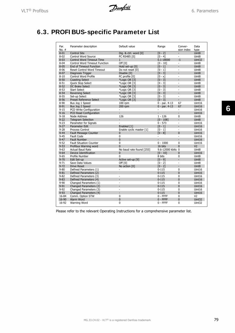
PROFIBUS-specific Parameter List 79
Object and Data Types Supported 80
7. Application Examples 83
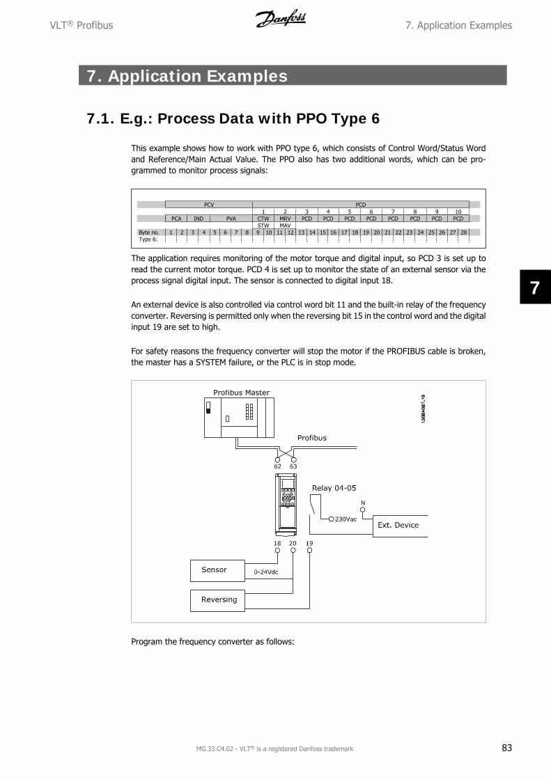
E.g.: Process Data with PPO Type 6 83
E.g.: Control Word Telegram using PPO Type 85
VLT® Profibus Contents
MG.33.C4.02 - VLT® is a registered Danfoss trademark 1
E.g.: Status Word Telegram using PPO Type 86
E.g.: PLC Programming 87
8. Troubleshooting 89
Diagnosis 89
Troubleshooting 89
LED Status 89
No Communication with the Drive 91
Warning 34 Appears even though Communication is Established 92
Drive Will Not Respond to Control Signals 92
Alarm and Warning Words 95
Fault Messages via DP Diagnosis 97
Extended Diagnosis 98
Index 99
Contents VLT® Profibus
2 MG.33.C4.02 - VLT® is a registered Danfoss trademark
1. Introduction
1.1.1. Copyright, Limitation of Liability and Revision Rights
This publication contains information proprietary to Danfoss A/S. By accepting and using thismanual the user agrees that the information contained herein will be used solely for operatingequipment from Danfoss A/S or equipment from other vendors provided that such equipment isintended for communication with Danfoss equipment over a PROFIBUS serial communication link.This publication is protected under the Copyright laws of Denmark and most other countries.
Danfoss A/S does not warrant that a software program produced according to the guidelines pro-vided in this manual will function properly in every physical, hardware or software environment.
Although Danfoss A/S has tested and reviewed the documentation within this manual, Danfoss A/S makes no warranty or representation, either express or implied, with respect to this documen-tation, including its quality, performance, or fitness for a particular purpose.
In no event shall Danfoss A/S be liable for direct, indirect, special, incidental, or consequentialdamages arising out of the use, or the inability to use information contained in this manual, evenif advised of the possibility of such damages. In particular, Danfoss A/S is not responsible for anycosts including but not limited to those incurred as a result of lost profits or revenue, loss ordamage of equipment, loss of computer programs, loss of data, the costs to substitute these, orany claims by third parties.
Danfoss A/S reserves the right to revise this publication at any time and to make changes in itscontents without prior notice or any obligation to notify previous users of such revisions orchanges.
VLT® Profibus 1. Introduction
MG.33.C4.02 - VLT® is a registered Danfoss trademark 3
1
1.2.1. Safety Note
The voltage of the frequency converter is dangerous whenever connected to mains.Incorrect installation of the motor, frequency converter or fieldbus may cause dam-age to the equipment, serious personal injury or death. Consequently, the instruc-tions in this manual, as well as national and local rules and safety regulations, mustbe complied with.
1.2.2. Safety Regulations
1. The frequency converter must be disconnected from mains if repair work is to be carriedout. Check that the mains supply has been disconnected and that the necessary time haspassed before removing motor and mains plugs.
2. The [STOP/RESET] key on the control panel of the frequency converter does not dis-connect the equipment from mains and is thus not to be used as a safety switch. 3.Correct protective earthing of the equipment must be established, the user must be pro-tected against supply voltage, and the motor must be protected against overload inaccordance with applicable national and local regulations.
3. Correct protective earthing of the equipment must be established, the user must be pro-tected against supply voltage, and the motor must be protected against overload inaccordance with applicable national and local regulations.
4. The earth leakage currents are higher than 3.5 mA.
5. Protection against motor overload is not included in the factory setting. If this functionis desired, set par. 1-90 Motor Thermal Protection to data value ETR trip or data valueETR warning. Note: The function is initialised at 1.16 x rated motor current and ratedmotor frequency. For the North American market: The ETR functions provide class 20motor overload protection in accordance with NEC.
6. Do not remove the plugs for the motor and mains supply while the frequency converteris connected to mains. Check that the mains supply has been disconnected and that thenecessary time has passed before removing motor and mains plugs.
7. Please note that the frequency converter has more voltage inputs than L1, L2 and L3,when load sharing (linking of DC intermediate circuit) and external 24 V DC have beeninstalled. Check that all voltage inputs have been disconnected and that the necessarytime has passed before commencing repair work.
1.2.3. Warning Against Unintended Start
1. The motor can be brought to a stop by means of digital commands, bus commands,references or a local stop, while the frequency converter is connected to mains. If per-sonal safety considerations make it necessary to ensure that no unintended start occurs,these stop functions are not sufficient.
2. While parameters are being changed, the motor may start. Consequently, the stop key[STOP/RESET] must always be activated; following which data can be modified.
3. A motor that has been stopped may start if faults occur in the electronics of the frequencyconverter, or if a temporary overload or a fault in the supply mains or the motor con-nection ceases.
1.2.4. Warning
Touching the electrical parts may be fatal - even after the equipment has been dis-connected from mains.
1. Introduction VLT® Profibus
4 MG.33.C4.02 - VLT® is a registered Danfoss trademark
1
Also make sure that other voltage inputs have been disconnected, such as external 24 V DC, loadsharing (linkage of DC intermediate circuit), as well as the motor connection for kinetic back up.
Please refer to the relevant Operating Instructions for further safety guidelines.
VLT® Profibus 1. Introduction
MG.33.C4.02 - VLT® is a registered Danfoss trademark 5
1
1.3. About this Manual
First time users can obtain the most essential information for quick installation and set-up in thesechapters:
IntroductionHow to InstallHow to Configure the SystemApplication Examples
For more detailed information including the full range of set-up options and diagnosis tools pleaserefer to the chapters:
How to Control the Frequency ConverterHow to Access the ParametersParametersTroubleshooting
1.4. About PROFIBUS
PROFIBUS is standardized in the international standards IEC 61158 and IEC 61784, and supportedby the member companies of the PROFIBUS International user community.
PROFIBUS International (PI) is the umbrella organization for all Regional PROFIBUS Associations(RPA) worldwide. PI has engaged PNO (PROFIBUS Nutzerorganisation e. V.), Germany, a non-profit organisation based in Karlsruhe, Germany, to establish Technical Committees and WorkingGroups in order to define and maintain the open and vendor independent PROFIBUS technology.Any member of PROFIBUS International may take an active part in maintenance and further de-velopment of the PROFIBUS technology. This guarantees openness and vendor independence ofthe PROFIBUS technology.
For access to the vast quantity of PROFIBUS literature including information and downloads forPROFIBUS DP and the PROFIdrive profile, please refer to www.profibus.com.
1.5. About PROFIBUS DP V1
By operating the frequency converter via a field bus you can reduce the capital cost of your SYS-TEM, communicate faster and more efficiently, and enjoy an easier user interface.
Using PROFIBUS DP V1 you are additionally guaranteed a product which has wide compatibility,a high level of availability and support, and which will be compatible with future versions. 10.
With the MCT 10 PC software tool you can control and configure your SYSTEM simultaneously,and monitor the entire SYSTEM more effectively for faster diagnosis, and better preventive main-tenance. Simplify commissioning, maintenance and documentation using MCT.
1. Introduction VLT® Profibus
6 MG.33.C4.02 - VLT® is a registered Danfoss trademark
1
Features of PROFIBUS DP V1:Capital savings
• PROFIBUS DP V1 permits very effective use of PLC I/O capacity, in effect expanding thevolume capacity of your existing PLC by up to two-thirds.
Fast and efficient communication
• short bus cycle times
• improved network efficiency
Easy to use
• transparent installation, diagnosis and parameterisation
Flexibility and compatibility
• Two different state machines can be selected: PROFIdrive profile or Danfoss FC profile
• Communication using PROFIBUS DP V1, Master Class 1 and Master Class 2
Future-proof investment
• Downward compatibility: New protocol extensions retain all the functions of the previousversions
• Continuous development of new application-oriented profiles
• Wide product availability
• Intelligent base for future technologies such as OPC, FDT/DTM, PROFINET
Technical features:
• Bus time out reaction
• PLC/CPU stop reaction
• Eight PPO types available
• Numerous relevant process data (PCD) types available
• Automatic detection of baud rate and PPO type
• Extended diagnosis available
• Alarms and warnings available as text messages within the PLC
• Equidistant bus cycle time configurable in PLC SYSTEM
• Improved network efficiency, since the cyclic parameter channel is no longer required
• Very short bus cycle times compared to industrial ethernet
• Backwards compatibility with DP
Features of MCT 10:
• Project-oriented PC tool, one tool for all VLT series
• Links to all Windows applications possible
• Supports Siemens CPs 5511 (PCMCIA) and 5611 (PCI- card), for PROFIBUS DP V1 MasterClass 2 connection
• Support of standard interfaces: COMx, USB, RS232 (FLUX)
• Siemens PG / Field PGs already have the necessary hardware ·
• “View” is highly individually configurable
• Backwards compatibility with Dos-Dialog (*.mnu) and WinDialog (*.vlt)
VLT® Profibus 1. Introduction
MG.33.C4.02 - VLT® is a registered Danfoss trademark 7
1
1.6. Technical Overview
1.6.1. Bus Topology
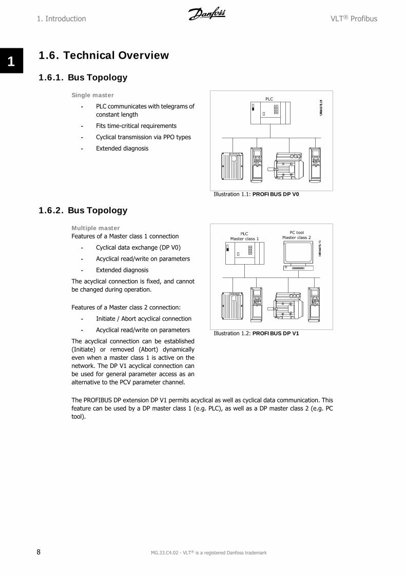
Single master
- PLC communicates with telegrams ofconstant length
- Fits time-critical requirements
- Cyclical transmission via PPO types
- Extended diagnosis
Illustration 1.1: PROFIBUS DP V0
1.6.2. Bus Topology
Multiple masterFeatures of a Master class 1 connection
- Cyclical data exchange (DP V0)
- Acyclical read/write on parameters
- Extended diagnosis
The acyclical connection is fixed, and cannotbe changed during operation.
Features of a Master class 2 connection:
- Initiate / Abort acyclical connection
- Acyclical read/write on parameters
The acyclical connection can be established(Initiate) or removed (Abort) dynamicallyeven when a master class 1 is active on thenetwork. The DP V1 acyclical connection canbe used for general parameter access as analternative to the PCV parameter channel.
Illustration 1.2: PROFIBUS DP V1
The PROFIBUS DP extension DP V1 permits acyclical as well as cyclical data communication. Thisfeature can be used by a DP master class 1 (e.g. PLC), as well as a DP master class 2 (e.g. PCtool).
1. Introduction VLT® Profibus
8 MG.33.C4.02 - VLT® is a registered Danfoss trademark
1
1.7. Assumptions
This manual assumes you are using a DANFOSS PROFIBUS Option Card in conjunction with aDANFOSS FC 100, 200 or 300 Series. It is also assumed that your master is a PLC or PC equippedwith a serial communication card supporting all the PROFIBUS communication services requiredby your application, and that all requirements stipulated in the PROFIBUS standard, as well asthose set up in the PROFIBUS Variable Speed Drive Profile and its company-specific implementa-tion PROFIdrive, as well as those pertaining to the VLT Variable Speed Drive are strictly observedas well as all limitations therein fully respected.
1.8. Hardware
These Operating Instructions relate to the Profibus fieldbus option type no. 130B1100 and typeno. 130B1200.The Profibus Option will be identified as: MCA 101 Profibus DP V1 in par. 15-60 Option in Slot A.
1.9. Background Knowledge
The DANFOSS PROFIBUS Option Card is designed to communicate with any master complyingwith the PROFIBUS standard. Familiarity with the PC or PLC you intend to use as a master in yourSYSTEM is assumed. Issues regarding hardware or software produced by other manufacturers arebeyond the scope of this manual, and are not the responsibility of DANFOSS.
If you have questions regarding set-up of master-to-master communication, or communication toa non-Danfoss slave, please consult the appropriate manuals
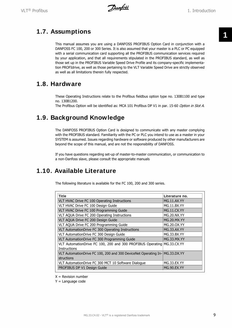
1.10. Available Literature
The following literature is available for the FC 100, 200 and 300 series.
Title Literature no.VLT HVAC Drive FC 100 Operating Instructions MG.11.AX.YYVLT HVAC Drive FC 100 Design Guide MG.11.BX.YYVLT HVAC Drive FC 100 Programming Guide MG.11.CX.YYVLT AQUA Drive FC 200 Operating Instructions MG.20.NX.YYVLT AQUA Drive FC 200 Design Guide MG.20.MX.YYVLT AQUA Drive FC 200 Programming Guide MG.20.OX.YYVLT AutomationDrive FC 300 Operating Instructions MG.33.AX.YYVLT AutomationDrive FC 300 Design Guide MG.33.BX.YYVLT AutomationDrive FC 300 Programming Guide MG.33.MX.YYVLT AutomationDrive FC 100, 200 and 300 PROFIBUS OperatingInstructions
MG.33.CX.YY
VLT AutomationDrive FC 100, 200 and 300 DeviceNet Operating In-structions
MG.33.C4.02 - VLT® is a registered Danfoss trademark 9
1
Please also refer to www.danfoss.com/drives for frequently asked questions and additional infor-mation.
1. Introduction VLT® Profibus
10 MG.33.C4.02 - VLT® is a registered Danfoss trademark
1
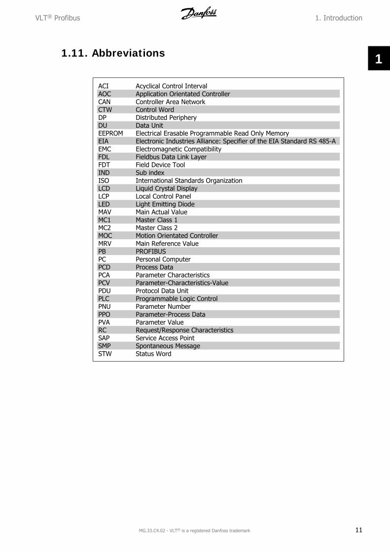
1.11. Abbreviations
ACI Acyclical Control IntervalAOC Application Orientated ControllerCAN Controller Area NetworkCTW Control WordDP Distributed PeripheryDU Data UnitEEPROM Electrical Erasable Programmable Read Only MemoryEIA Electronic Industries Alliance: Specifier of the EIA Standard RS 485-AEMC Electromagnetic CompatibilityFDL Fieldbus Data Link LayerFDT Field Device ToolIND Sub indexISO International Standards OrganizationLCD Liquid Crystal DisplayLCP Local Control PanelLED Light Emitting DiodeMAV Main Actual ValueMC1 Master Class 1MC2 Master Class 2MOC Motion Orientated ControllerMRV Main Reference ValuePB PROFIBUSPC Personal ComputerPCD Process DataPCA Parameter CharacteristicsPCV Parameter-Characteristics-ValuePDU Protocol Data UnitPLC Programmable Logic ControlPNU Parameter NumberPPO Parameter-Process DataPVA Parameter ValueRC Request/Response CharacteristicsSAP Service Access PointSMP Spontaneous MessageSTW Status Word
VLT® Profibus 1. Introduction
MG.33.C4.02 - VLT® is a registered Danfoss trademark 11
1
2. How to Install VLT® Profibus
12 MG.33.C4.02 - VLT® is a registered Danfoss trademark
2
2. How to Install
2.1. Cabling
2.1.1. Cable Lengths and Number of Codes
The maximum cable length allowable in one segment is dependent on the transmission speed.The total cable length includes drop cables if any. A drop cable is the connection from the mainbus cable to each node if a T-connection is used instead of permissible cable length and maximumnumber of nodes/frequency converters with 1, 2, 3 and 4 bus segments.
Drop cable connection (i.e. T-connection) beyond the cable lengths indicated is not recommended,due to the increased risk of reflection occurring. Instead, Danfoss recommends direct connectionof the frequency converter.
Note that a repeater is a node in both of the two segments it connects. The number of frequencyconverters is based on a single master SYSTEM. If there are two or more masters (e.g. PC tools),the number of frequency converters must be reduced correspondingly.
- Cable type: twisted in pairs, 1 x 2, or 2 x 2, or 1 x 4 wires
- Screening: Copper-braided screen or braided screen and foil screen
Use of the same cable type throughout the entire network is recommended to avoid impedancemismatch.
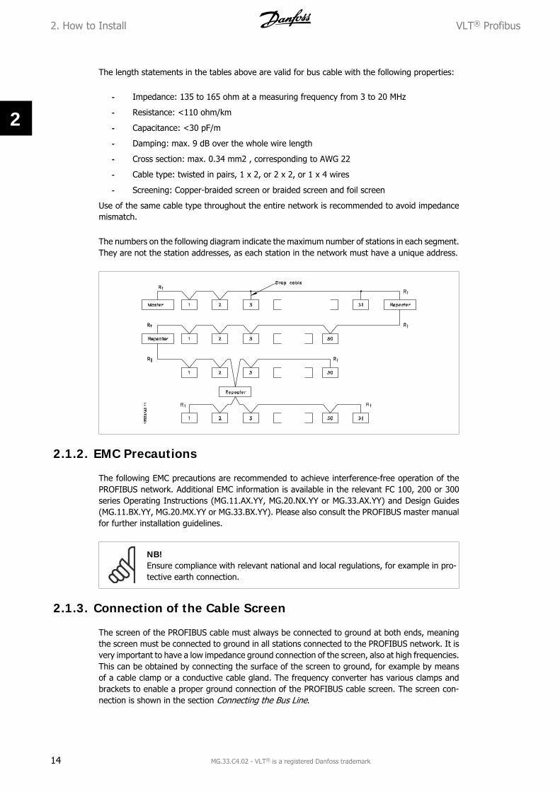
The numbers on the following diagram indicate the maximum number of stations in each segment.They are not the station addresses, as each station in the network must have a unique address.
2.1.2. EMC Precautions
The following EMC precautions are recommended to achieve interference-free operation of thePROFIBUS network. Additional EMC information is available in the relevant FC 100, 200 or 300series Operating Instructions (MG.11.AX.YY, MG.20.NX.YY or MG.33.AX.YY) and Design Guides(MG.11.BX.YY, MG.20.MX.YY or MG.33.BX.YY). Please also consult the PROFIBUS master manualfor further installation guidelines.
NB!Ensure compliance with relevant national and local regulations, for example in pro-tective earth connection.
2.1.3. Connection of the Cable Screen
The screen of the PROFIBUS cable must always be connected to ground at both ends, meaningthe screen must be connected to ground in all stations connected to the PROFIBUS network. It isvery important to have a low impedance ground connection of the screen, also at high frequencies.This can be obtained by connecting the surface of the screen to ground, for example by meansof a cable clamp or a conductive cable gland. The frequency converter has various clamps andbrackets to enable a proper ground connection of the PROFIBUS cable screen. The screen con-nection is shown in the section Connecting the Bus Line.
2. How to Install VLT® Profibus
14 MG.33.C4.02 - VLT® is a registered Danfoss trademark
2
2.1.4. Earth Connection
It is important that all stations connected to the PROFIBUS network are connected to the sameearth potential. The earth connection must have a low HF (high frequency) impedance. This canbe achieved by connecting a large surface area of the cabinet to earth, for example by mountingthe frequency converter on a conductive rear plate. Particularly when there are long distancesbetween the stations in a PROFIBUS network, it can be necessary to use additional potentialequalizing cables, connecting the individual stations to the same earth potential.
2.1.5. Cable Routing
The PROFIBUS communication cable must be kept away from motor and brake resistor cables toavoid coupling of high frequency noise from one cable to the other. Normally a distance of 200mm is sufficient, but maintaining the greatest possible distance between cables is generally rec-ommended, especially where cables run in parallel over long distances.
If the PROFIBUS cable must cross a motor cable or brake resistor cable, the cables must cross atan angle of 90°.
VLT® Profibus 2. How to Install
MG.33.C4.02 - VLT® is a registered Danfoss trademark 15
2
2.1.6. Connecting the Bus Line
Proper termination of the bus line is essential.A mismatch of impedance may result in re-flections on the line that will corrupt datatransmission.
- The PROFIBUS Option Card has asuitable termination, activated byswitch 1 located on the Profibus op-tion. The switches must be on to ter-minate the bus. The factory settingis off.
- Nodes at the physical ends of eachsegment must be terminated.
- When power to the PROFIBUS cardis down, please note that the termi-nation is still active, although notfunctional.
- Most masters and repeaters areequipped with their own termination.
- If an external termination circuit con-sisting of three resistors is connectedto the bus line, a 5V DC power supplymust be used. Please note that thispower supply must be galvanicallyisolated from the a.c. line.
- The CS-pin on the Profibus connec-tor is Control Select. When optiongoes into active state and sends atelegram, the CS pin goes high (+5Volts). This can be used to controloptical transmitters etc. or for trig-gering measurement equipment likean oscilloscope.
- D-sub 9 connector.If desired, a D-sub 9 adaptor can beadded as an option. The Profibus D-sub 9 adaptor has the type no:130B1112.N.B.: If the D-sub 9 adaptor is used,please be aware that the terminationswitch on the Profibus option is setto OFF, to avoid double termination.as the Profibus D-sub 9 connector al-so features a termination switch.
Illustration 2.1: 62 = RxD/TxD-P red cable (Sie-mens B)63 = RxD/TxD-N green cable (Siemens A)
2. How to Install VLT® Profibus
16 MG.33.C4.02 - VLT® is a registered Danfoss trademark
2
2.2. How to Install Option in Drive
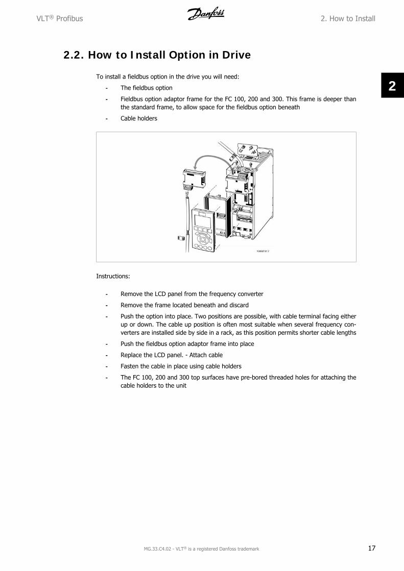
To install a fieldbus option in the drive you will need:
- The fieldbus option
- Fieldbus option adaptor frame for the FC 100, 200 and 300. This frame is deeper thanthe standard frame, to allow space for the fieldbus option beneath
- Cable holders
Instructions:
- Remove the LCD panel from the frequency converter
- Remove the frame located beneath and discard
- Push the option into place. Two positions are possible, with cable terminal facing eitherup or down. The cable up position is often most suitable when several frequency con-verters are installed side by side in a rack, as this position permits shorter cable lengths
- Push the fieldbus option adaptor frame into place
- Replace the LCD panel. - Attach cable
- Fasten the cable in place using cable holders
- The FC 100, 200 and 300 top surfaces have pre-bored threaded holes for attaching thecable holders to the unit
VLT® Profibus 2. How to Install
MG.33.C4.02 - VLT® is a registered Danfoss trademark 17
2
3. How to Configure the System VLT® Profibus
18 MG.33.C4.02 - VLT® is a registered Danfoss trademark
3
3. How to Configure the System
3.1. Configure the PROFIBUS Network
All PROFIBUS stations that are connected to the same bus network must have a unique stationaddress.
The PROFIBUS address of the frequency converter can be selected via:
- Hardware switches
- Par. 9-18 Node address
- The PROFIBUS command SSA “Set Station Address”
3.1.1. Setting the PROFIBUS Address using the Hardware Switches
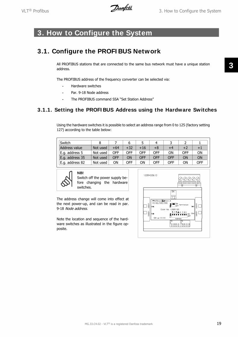
Using the hardware switches it is possible to select an address range from 0 to 125 (factory setting127) according to the table below:
Switch 8 7 6 5 4 3 2 1Address value Not used +64 +32 +16 +8 +4 +2 +1E.g. address 5 Not used OFF OFF OFF OFF ON OFF ONE.g. address 35 Not used OFF ON OFF OFF OFF ON ONE.g. address 82 Not used ON OFF ON OFF OFF ON OFF
NB!Switch off the power supply be-fore changing the hardwareswitches.
The address change will come into effect atthe next power-up, and can be read in par.9-18 Node address.
Note the location and sequence of the hard-ware switches as illustrated in the figure op-posite.
VLT® Profibus 3. How to Configure the System
MG.33.C4.02 - VLT® is a registered Danfoss trademark 19
3
Setting the PROFIBUS Address via par. 9-18 Node address:Setting the address via par. 9-18 Node address or the Profibus SSA-command is possible, if thehardware switches are set to 126 or 127 (factory switch setting). The address change will comeinto effect at the next power-up.
Setting the PROFIBUS Address with “Set Station Address” Command:Setting the address via the "Set Station Address" command is possible, if the hardware switch isset to 126 or 127 (factory switch setting). Using the "Set Station Address" command it is possibleto lock the programmed address, which makes it impossible to change the address using thiscommand. The address setting can be unlocked by changing the par. 9-18 Node address or theaddress switch, followed by a power cycle. A new address is effective immediately after the "SetStation Address" command.
3.2. Configure the Master
3.2.1. GSD File
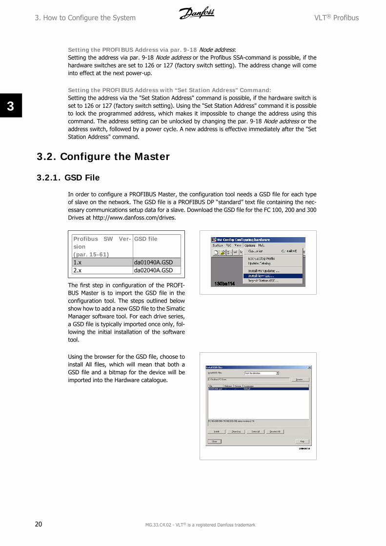
In order to configure a PROFIBUS Master, the configuration tool needs a GSD file for each typeof slave on the network. The GSD file is a PROFIBUS DP “standard” text file containing the nec-essary communications setup data for a slave. Download the GSD file for the FC 100, 200 and 300Drives at http://www.danfoss.com/drives.
Profibus SW Ver-sion(par. 15-61)
GSD file
1.x da01040A.GSD2.x da02040A.GSD
The first step in configuration of the PROFI-BUS Master is to import the GSD file in theconfiguration tool. The steps outlined belowshow how to add a new GSD file to the SimaticManager software tool. For each drive series,a GSD file is typically imported once only, fol-lowing the initial installation of the softwaretool.
Using the browser for the GSD file, choose toinstall All files, which will mean that both aGSD file and a bitmap for the device will beimported into the Hardware catalogue.
3. How to Configure the System VLT® Profibus
20 MG.33.C4.02 - VLT® is a registered Danfoss trademark
3
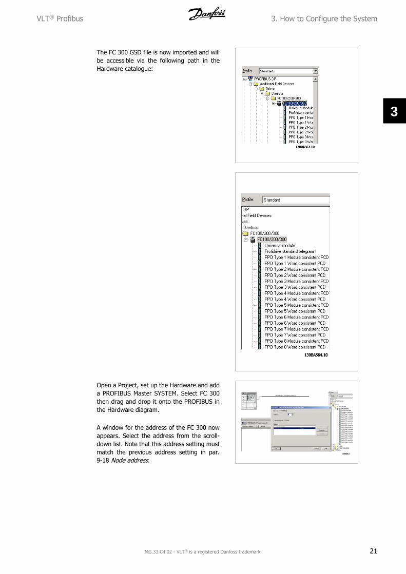
The FC 300 GSD file is now imported and willbe accessible via the following path in theHardware catalogue:
Open a Project, set up the Hardware and adda PROFIBUS Master SYSTEM. Select FC 300then drag and drop it onto the PROFIBUS inthe Hardware diagram.
A window for the address of the FC 300 nowappears. Select the address from the scroll-down list. Note that this address setting mustmatch the previous address setting in par.9-18 Node address.
VLT® Profibus 3. How to Configure the System
MG.33.C4.02 - VLT® is a registered Danfoss trademark 21
3
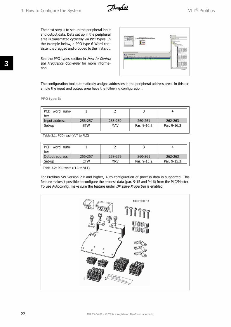
The next step is to set up the peripheral inputand output data. Data set up in the peripheralarea is transmitted cyclically via PPO types. Inthe example below, a PPO type 6 Word con-sistent is dragged and dropped to the first slot.
See the PPO types section in How to Controlthe Frequency Converter for more informa-tion.
The configuration tool automatically assigns addresses in the peripheral address area. In this ex-ample the input and output area have the following configuration:
For Profibus SW version 2.x and higher, Auto-configuration of process data is supported. Thisfeature makes it possible to configure the process data (par. 9-15 and 9-16) from the PLC/Master.To use Autoconfig, make sure the feature under DP slave Properties is enabled.
3. How to Configure the System VLT® Profibus
22 MG.33.C4.02 - VLT® is a registered Danfoss trademark
3
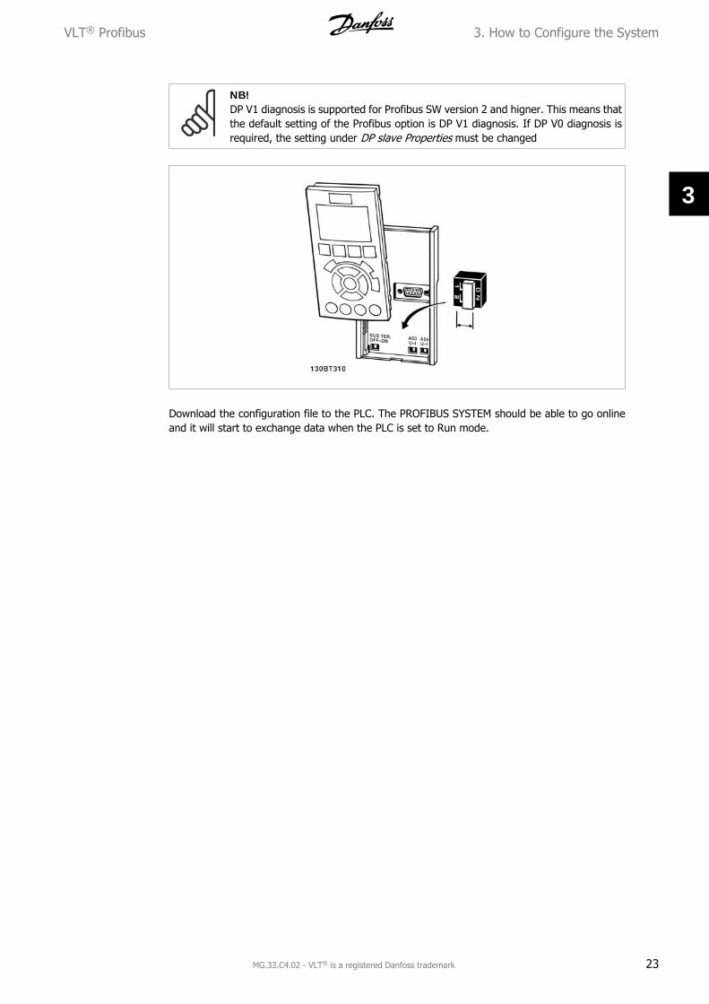
NB!DP V1 diagnosis is supported for Profibus SW version 2 and higner. This means thatthe default setting of the Profibus option is DP V1 diagnosis. If DP V0 diagnosis isrequired, the setting under DP slave Properties must be changed
Download the configuration file to the PLC. The PROFIBUS SYSTEM should be able to go onlineand it will start to exchange data when the PLC is set to Run mode.
VLT® Profibus 3. How to Configure the System
MG.33.C4.02 - VLT® is a registered Danfoss trademark 23
3
3.3. Configure the Frequency Converter
3.3.1. VLT Parameters
Pay particular attention to the following parameters when configuring the frequency converterwith a PROFIBUS interface.
• Par. 0-40 [Hand on] key on LCP. If the Hand button on the frequency converter is acti-vated, control of the drive via the PROFIBUS interface is disabled
• After an initial power up the frequency converter will automatically detect whether afieldbus option is installed in slot A, and set par. 8-02 Control word source to [Option A].If an option is added or changed in or removed from an already commissioned drive, itwill not change par. 8-02 but enter Trip Mode, and the drive will display an error
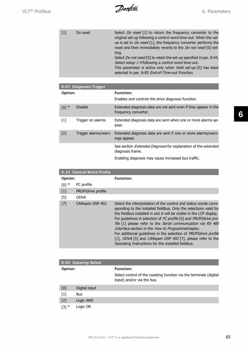
• Par. 8-10 Control word profile. Choose between the Danfoss FC Profile and the PROFI-drive profile
• Par. 8-50 to 8-56. Selection of how to gate PROFIBUS control commands with digitalinput command of the control card
• Par. 8-03 to 8-05. The reaction in the event of a bus time out is set via these parameters
• Par. 9-18 Node address
• Par. 8-07 Diagnosis trigger
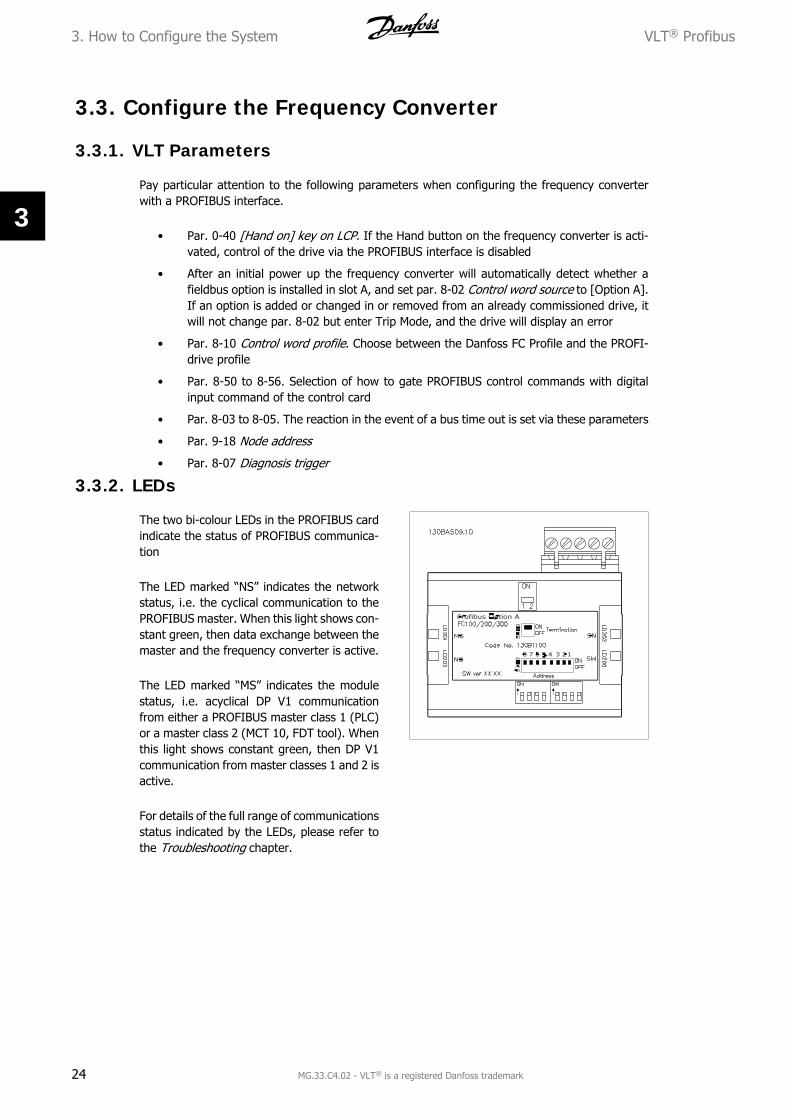
3.3.2. LEDs
The two bi-colour LEDs in the PROFIBUS cardindicate the status of PROFIBUS communica-tion
The LED marked “NS” indicates the networkstatus, i.e. the cyclical communication to thePROFIBUS master. When this light shows con-stant green, then data exchange between themaster and the frequency converter is active.
The LED marked “MS” indicates the modulestatus, i.e. acyclical DP V1 communicationfrom either a PROFIBUS master class 1 (PLC)or a master class 2 (MCT 10, FDT tool). Whenthis light shows constant green, then DP V1communication from master classes 1 and 2 isactive.
For details of the full range of communicationsstatus indicated by the LEDs, please refer tothe Troubleshooting chapter.
3. How to Configure the System VLT® Profibus
24 MG.33.C4.02 - VLT® is a registered Danfoss trademark
3
4. How to Control the Frequency Converter
4.1. PPO Types
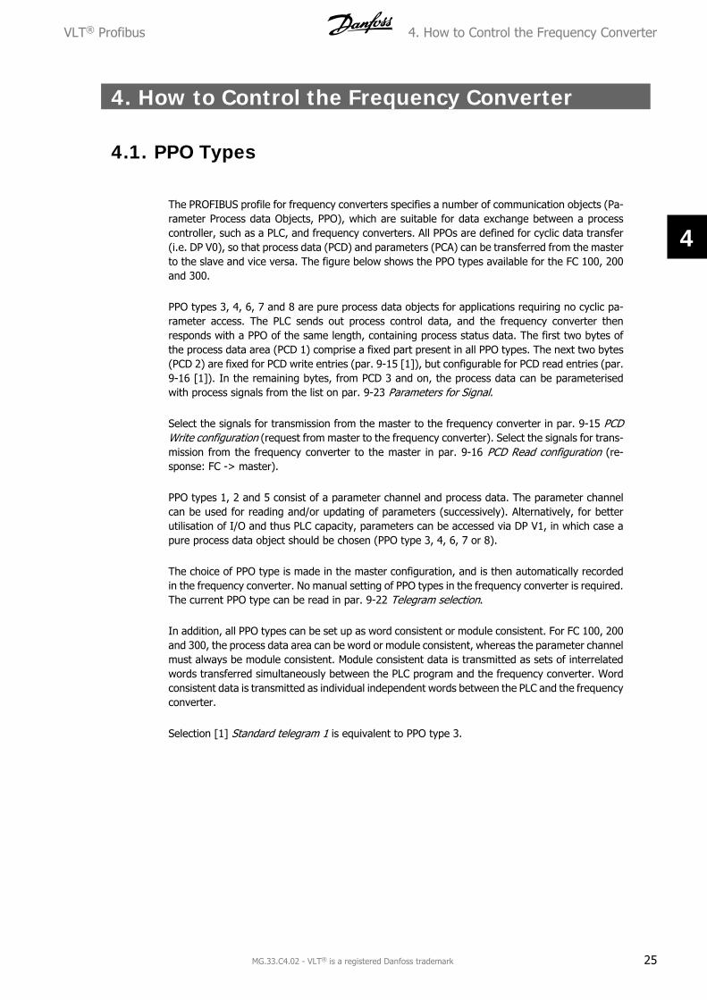
The PROFIBUS profile for frequency converters specifies a number of communication objects (Pa-rameter Process data Objects, PPO), which are suitable for data exchange between a processcontroller, such as a PLC, and frequency converters. All PPOs are defined for cyclic data transfer(i.e. DP V0), so that process data (PCD) and parameters (PCA) can be transferred from the masterto the slave and vice versa. The figure below shows the PPO types available for the FC 100, 200and 300.
PPO types 3, 4, 6, 7 and 8 are pure process data objects for applications requiring no cyclic pa-rameter access. The PLC sends out process control data, and the frequency converter thenresponds with a PPO of the same length, containing process status data. The first two bytes ofthe process data area (PCD 1) comprise a fixed part present in all PPO types. The next two bytes(PCD 2) are fixed for PCD write entries (par. 9-15 [1]), but configurable for PCD read entries (par.9-16 [1]). In the remaining bytes, from PCD 3 and on, the process data can be parameterisedwith process signals from the list on par. 9-23 Parameters for Signal.
Select the signals for transmission from the master to the frequency converter in par. 9-15 PCDWrite configuration (request from master to the frequency converter). Select the signals for trans-mission from the frequency converter to the master in par. 9-16 PCD Read configuration (re-sponse: FC -> master).
PPO types 1, 2 and 5 consist of a parameter channel and process data. The parameter channelcan be used for reading and/or updating of parameters (successively). Alternatively, for betterutilisation of I/O and thus PLC capacity, parameters can be accessed via DP V1, in which case apure process data object should be chosen (PPO type 3, 4, 6, 7 or 8).
The choice of PPO type is made in the master configuration, and is then automatically recordedin the frequency converter. No manual setting of PPO types in the frequency converter is required.The current PPO type can be read in par. 9-22 Telegram selection.
In addition, all PPO types can be set up as word consistent or module consistent. For FC 100, 200and 300, the process data area can be word or module consistent, whereas the parameter channelmust always be module consistent. Module consistent data is transmitted as sets of interrelatedwords transferred simultaneously between the PLC program and the frequency converter. Wordconsistent data is transmitted as individual independent words between the PLC and the frequencyconverter.
Selection [1] Standard telegram 1 is equivalent to PPO type 3.
VLT® Profibus 4. How to Control the Frequency Converter
MG.33.C4.02 - VLT® is a registered Danfoss trademark 25
4
PC
VPC
D
12
34
56
78
910
Par.
9-1
5 +
9-1
6 in
dex.
no.
:[0
][1
][2
][3
][4
][5
][6
][7
][8
][9
]
PC
AIN
DPV
ACT
WM
RVPC
DPC
DPC
DPC
DPC
DPC
DPC
DPC
D
ST
WM
AV
Byte
no.
12
34
56
78
910
1112
1314
1516
1718
1920
2122
2324
2526
2728
Ty
pe 1
:
Type
2:
Ty
pe 3
:
Type
4:
Ty
pe 5
:
Ty
pe 6
:
Type
7:
Ty
pe 8
:
PCV:
Para
met
er C
hara
cter
istic
s Va
lue
CTW
:Co
ntro
l wor
dPC
D:
Proc
ess
Dat
aST
W:
Stat
us w
ord
PCA:
Para
met
er C
hara
cter
istic
s (B
ytes
1, 2)
MRV:
Mai
n re
fere
nce
valu
eIN
D:
Sub
inde
x (B
yte
3. B
yte
4 is
not
use
d)M
AV:
Mai
n ac
tual
val
ue (
Actu
al o
utpu
t fr
eque
ncy)
PVA:
Para
met
er v
alue
(By
tes
5 to
8)
4. How to Control the Frequency Converter VLT® Profibus
26 MG.33.C4.02 - VLT® is a registered Danfoss trademark
4
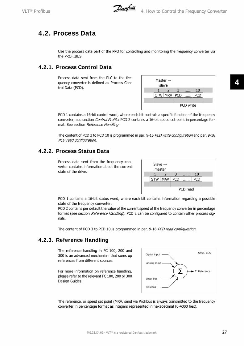
4.2. Process Data
Use the process data part of the PPO for controlling and monitoring the frequency converter viathe PROFIBUS.
4.2.1. Process Control Data
Process data sent from the PLC to the fre-quency converter is defined as Process Con-trol Data (PCD).
Master →slave
1 2 3 ...... 10 CTW MRV PCD ...... PCD PCD write
PCD 1 contains a 16-bit control word, where each bit controls a specific function of the frequencyconverter, see section Control Profile. PCD 2 contains a 16-bit speed set point in percentage for-mat. See section Reference Handling
The content of PCD 3 to PCD 10 is programmed in par. 9-15 PCD write configuration and par. 9-16PCD read configuration.
4.2.2. Process Status Data
Process data sent from the frequency con-verter contains information about the currentstate of the drive.
Slave →master
1 2 3 ...... 10 STW MAV PCD ...... PCD PCD read
PCD 1 contains a 16-bit status word, where each bit contains information regarding a possiblestate of the frequency converter.PCD 2 contains per default the value of the current speed of the frequency converter in percentageformat (see section Reference Handling). PCD 2 can be configured to contain other process sig-nals.
The content of PCD 3 to PCD 10 is programmed in par. 9-16 PCD read configuration.
4.2.3. Reference Handling
The reference handling in FC 100, 200 and300 is an advanced mechanism that sums upreferences from different sources.
For more information on reference handling,please refer to the relevant FC 100, 200 or 300Design Guides.
The reference, or speed set point (MRV, send via Profibus is always transmitted to the frequencyconverter in percentage format as integers represented in hexadecimal (0-4000 hex).
VLT® Profibus 4. How to Control the Frequency Converter
MG.33.C4.02 - VLT® is a registered Danfoss trademark 27
4
The reference (MRV) and feedback (MAV) are always scaled equally.
Depending on the setting of par. 3-00 Reference Range the reference and MAV are scaled ac-cordingly:
NB!If par. 3-00 is set to [0] Min - Max, a negative reference will be handled as 0%.
The actual output of the frequency converter is limited by the speed limit parameters Motor Low/High Speed Limit [RPM/Hz] in par. 4-11 to 4-14.The final speed limit is set by par. 4-19 Max Output Frequency.
The reference and the MAV have the formatwhich appears from the table
NB!Negative numbers are formed as two's complement.
4. How to Control the Frequency Converter VLT® Profibus
28 MG.33.C4.02 - VLT® is a registered Danfoss trademark
4
NB!The data type for MRV and MAV is a N2 16 bit standardised value, meaning it canexpress a range from -200% to +200% (8001 to 7FFF).
Par. 1-00 Configuration Mode set to [0] Speed open loop.Par. 3-00 Reference Range set to [0] Min - Max.Par. 3-02 Min Reference set to 100 RPM.Par. 3-03 Max Reference set to 3000 RPM.
In process control operation par. 1-00 Configuration Mode is set to [3] Process.The reference range in par. 3-00 is alway [0] Min - Max.- MRV represents the process setpoint.- MAV expresses the actual process feedback (range +/1 200%).
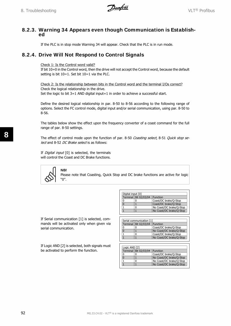
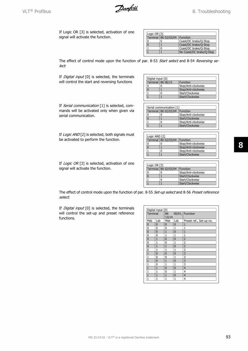
4.2.5. Influence of the Digital Input Terminals upon FC Control Mode,Par. 8-50 to 8-56
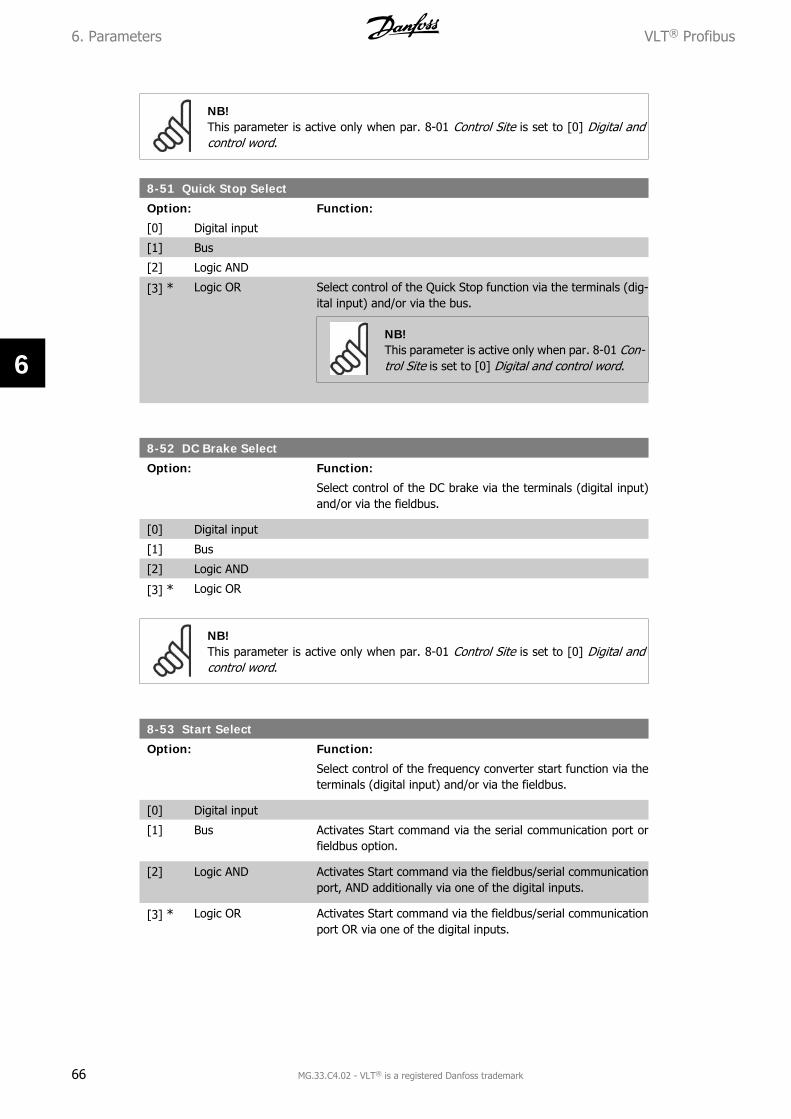
The influence of the digital input terminals upon control of the frequency converter can be pro-grammed in par. 8-50 to 8-56. Please note the par. 8-01 Control Site overrules the settings in par.8-50 to 8-56, and Terminal 37 Coasting Stop (safe) overrules any parameter.
Each of the digital input signals can be programmed to logic AND, logic OR, or to have no relationto the corresponding bit in the control word. In this way a specific control command i.e. stop /coast, can be initiated by fieldbus only, fieldbus AND Digital Input, or Ether Fieldbus OR Digitalinput terminal.
In order to control the frequency converter via PROFIBUS, par. 8-50 Coasting se-lect must be set to either Bus [1], or to Logic AND [2], and par. 8-01 Control Sitemust be set to [0] or [2].
More detailed information and examples of logical relationship options are provided in the Trou-bleshooting chapter.
VLT® Profibus 4. How to Control the Frequency Converter
MG.33.C4.02 - VLT® is a registered Danfoss trademark 29
4
4.3. Control Profile
The frequency converter can be controlled according to the PROFIdrive profile, or the Danfoss FCprofile. Select the desired control profile in par. 8-10 Control word profile. The choice of profileaffects the control and status word only.
The PROFIdrive control profile and Danfoss FC control profile sections provide a detailed descrip-tion of control and status data.
4.4. PROFIdrive Control Profile
4.4.1. PROFIdrive Control Profile
This section describes the functionality of the control word and status word in the PROFIdriveprofile. Select this profile by setting par. 8-10 Control word profile to PROFIdrive.
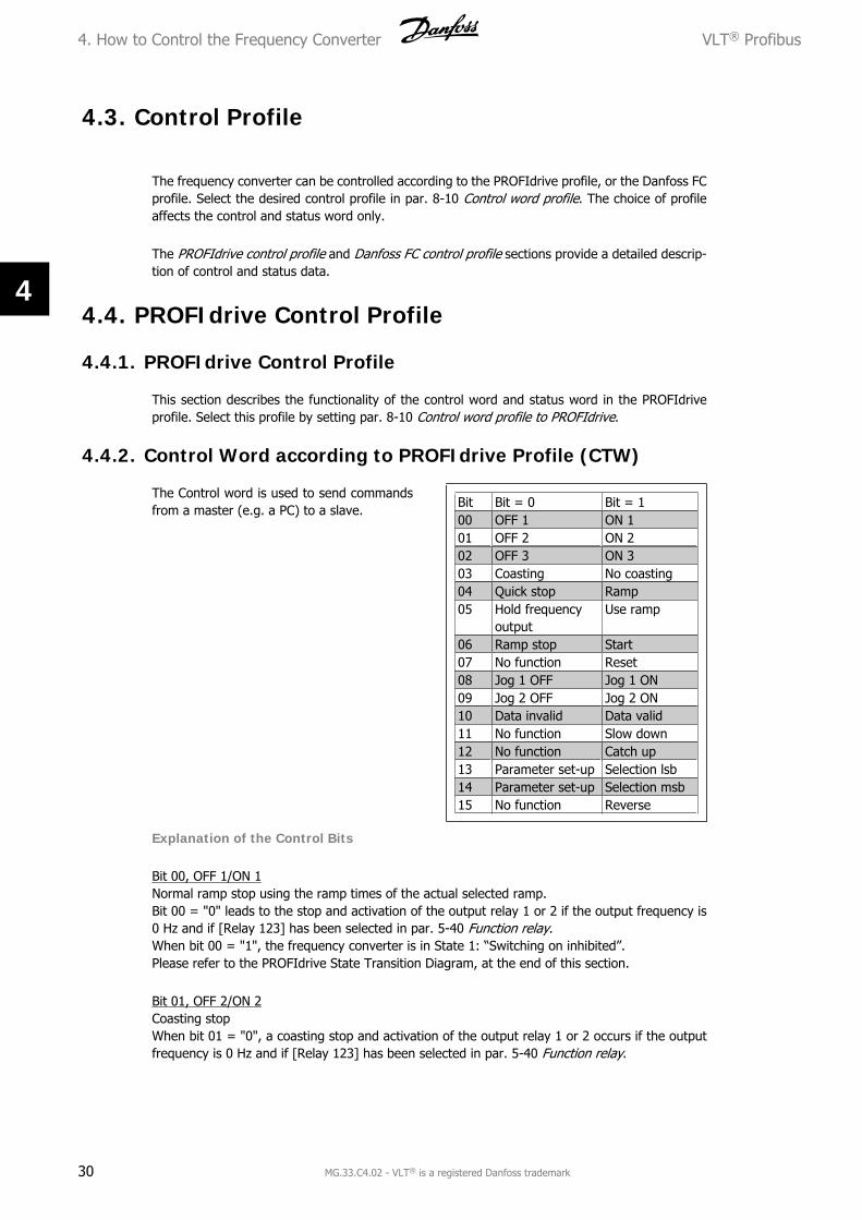
4.4.2. Control Word according to PROFIdrive Profile (CTW)
The Control word is used to send commandsfrom a master (e.g. a PC) to a slave.
Bit Bit = 0 Bit = 100 OFF 1 ON 101 OFF 2 ON 202 OFF 3 ON 303 Coasting No coasting04 Quick stop Ramp05 Hold frequency
outputUse ramp
06 Ramp stop Start07 No function Reset08 Jog 1 OFF Jog 1 ON09 Jog 2 OFF Jog 2 ON10 Data invalid Data valid11 No function Slow down12 No function Catch up13 Parameter set-up Selection lsb14 Parameter set-up Selection msb15 No function Reverse
Explanation of the Control Bits
Bit 00, OFF 1/ON 1Normal ramp stop using the ramp times of the actual selected ramp.Bit 00 = "0" leads to the stop and activation of the output relay 1 or 2 if the output frequency is0 Hz and if [Relay 123] has been selected in par. 5-40 Function relay.When bit 00 = "1", the frequency converter is in State 1: “Switching on inhibited”.Please refer to the PROFIdrive State Transition Diagram, at the end of this section.
Bit 01, OFF 2/ON 2Coasting stopWhen bit 01 = "0", a coasting stop and activation of the output relay 1 or 2 occurs if the outputfrequency is 0 Hz and if [Relay 123] has been selected in par. 5-40 Function relay.
4. How to Control the Frequency Converter VLT® Profibus
30 MG.33.C4.02 - VLT® is a registered Danfoss trademark
4
When bit 01 = "1", the frequency converter is in State 1: “Switching on inhibited”. Please refer tothe PROFIdrive State Transition Diagram, at the end of this section.
Bit 02, OFF 3/ON 3Quick stop using the ramp time of par. 3-81 Quick stop ramp time. When bit 02 = "0", a quickstop and activation of the output relay 1 or 2 occurs if the output frequency is 0 Hz and if [Relay123] has been selected in par. 5-40 Function relay.When bit 02 = "1", the frequency converter is in State 1: “Switching on inhibited”.Please refer to the PROFIdrive State Transition Diagram, at the end of this section.
Bit 03, Coasting/No coastingCoasting stop Bit 03 = "0" leads to a stop. When bit 03 = "1", the frequency converter can startif the other start conditions are satisfied.
NB!The selection in par. 8-50 Coasting select determines how bit 03 is linked with thecorresponding function of the digital inputs.
Bit 04, Quick stop/RampQuick stop using the ramp time of par. 3-81 Quick stop ramp time.When bit 04 = "0", a quick stop occurs.When bit 04 = "1", the frequency converter can start if the other start conditions are satisfied.
NB!The selection in par. 8-51 Quick stop select determines how bit 04 is linked with thecorresponding function of the digital inputs.
Bit 05, Hold frequency output/Use rampWhen bit 05 = "0", the current output frequency is being maintained even if the reference valueis modified.When bit 05 = "1", the frequency converter can perform its regulating function again; operationoccurs according to the respective reference value.
Bit 06, Ramp stop/StartNormal ramp stop using the ramp times of the actual ramp as selected. In addition, activation ofthe output relay 01 or 04 if the output frequency is 0 Hz if Relay 123 has been selected in par.5-40 Function relay. Bit 06 = "0" leads to a stop. When bit 06 = "1", the frequency converter canstart if the other start conditions are satisfied.
NB!The selection in par. 8-53 Start select determines how bit 06 is linked with the cor-responding function of the digital inputs.
Bit 07, No function/ResetReset after switching off.Acknowledges event in fault buffer.When bit 07 = "0", no reset occurs.When there is a slope change of bit 07 to "1", a reset occurs after switching off.
VLT® Profibus 4. How to Control the Frequency Converter
MG.33.C4.02 - VLT® is a registered Danfoss trademark 31
4
Bit 08, Jog 1 OFF/ONActivation of the pre-programmed speed in par. 8-90 Bus Jog 1 speed. JOG 1 is only possible ifbit 04 = "0" and bit 00 - 03 = "1".
Bit 09, Jog 2 OFF/ONActivation of the pre-programmed speed in par. 8-91 Bus Jog 2 speed. JOG 2 is only possible ifbit 04 = "0" and bit 00 - 03 = "1".
Bit 10, Data invalid/validIs used to tell the frequency converter whether the control word is to be used or ignored. Bit 10= “0” causes the control word to be ignored, Bit 10 = “1” causes the control word to be used.This function is relevant, because the control word is always contained in the telegram, regardlessof which type of telegram is used, i.e. it is possible to turn off the control word if you do not wishto use it in connection with updating or reading parameters.
Bit 11, No function/Slow downIs used to reduce the speed reference value by the amount given in par. 3-12 Catch up/slowdown value. When bit 11 = "0", no modification of the reference value occurs. When bit 11 = "1",the reference value is reduced.
Bit 12, No function/Catch upIs used to increase the speed reference value by the amount given in par. 3-12 Catch up/slowdown value.When bit 12 = "0", no modification of the reference value occurs.When bit 12 = "1", the reference value is increased.If both - slowing down and accelerating - are activated (bit 11 and 12 = "1"), slowing down haspriority, i.e. the speed reference value will be reduced.
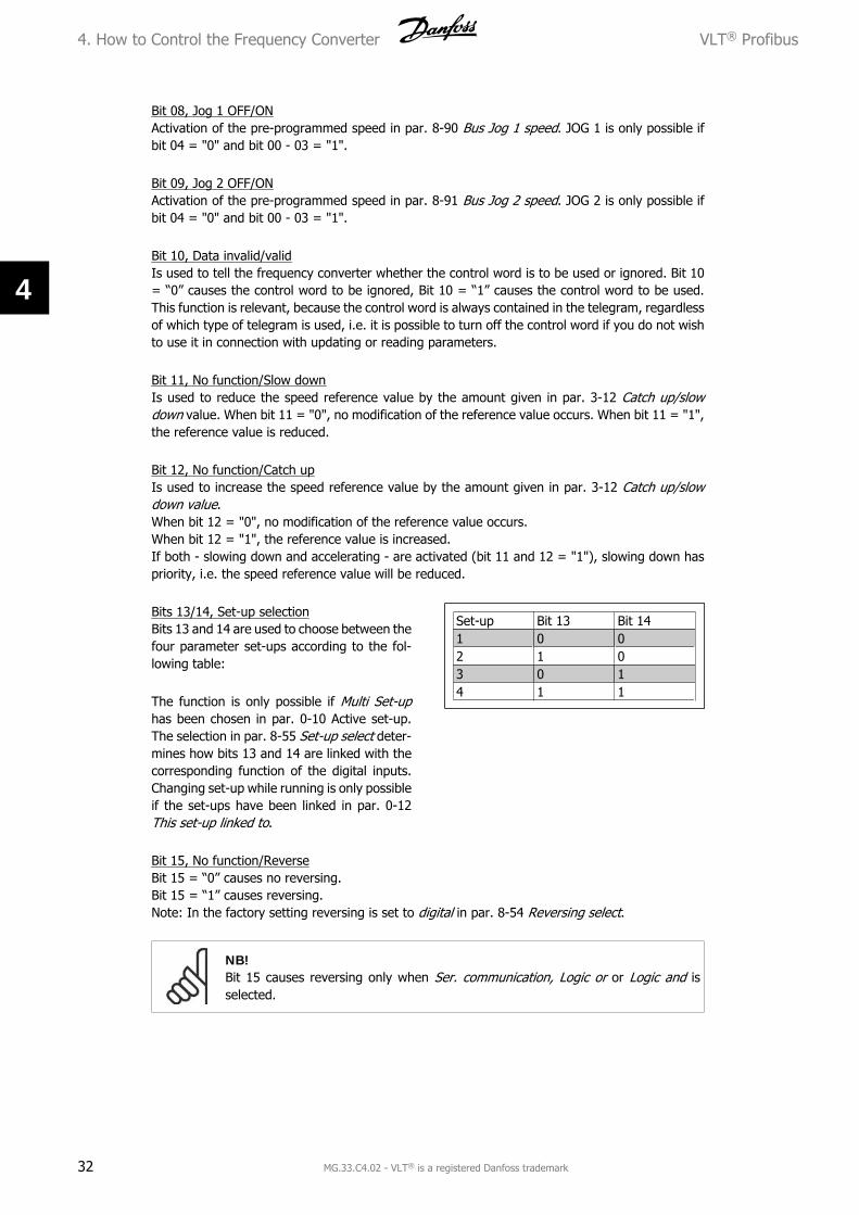
Bits 13/14, Set-up selectionBits 13 and 14 are used to choose between thefour parameter set-ups according to the fol-lowing table:
The function is only possible if Multi Set-uphas been chosen in par. 0-10 Active set-up.The selection in par. 8-55 Set-up select deter-mines how bits 13 and 14 are linked with thecorresponding function of the digital inputs.Changing set-up while running is only possibleif the set-ups have been linked in par. 0-12This set-up linked to.
Set-up Bit 13 Bit 141 0 02 1 03 0 14 1 1
Bit 15, No function/ReverseBit 15 = “0” causes no reversing.Bit 15 = “1” causes reversing.Note: In the factory setting reversing is set to digital in par. 8-54 Reversing select.
NB!Bit 15 causes reversing only when Ser. communication, Logic or or Logic and isselected.
4. How to Control the Frequency Converter VLT® Profibus
32 MG.33.C4.02 - VLT® is a registered Danfoss trademark
4
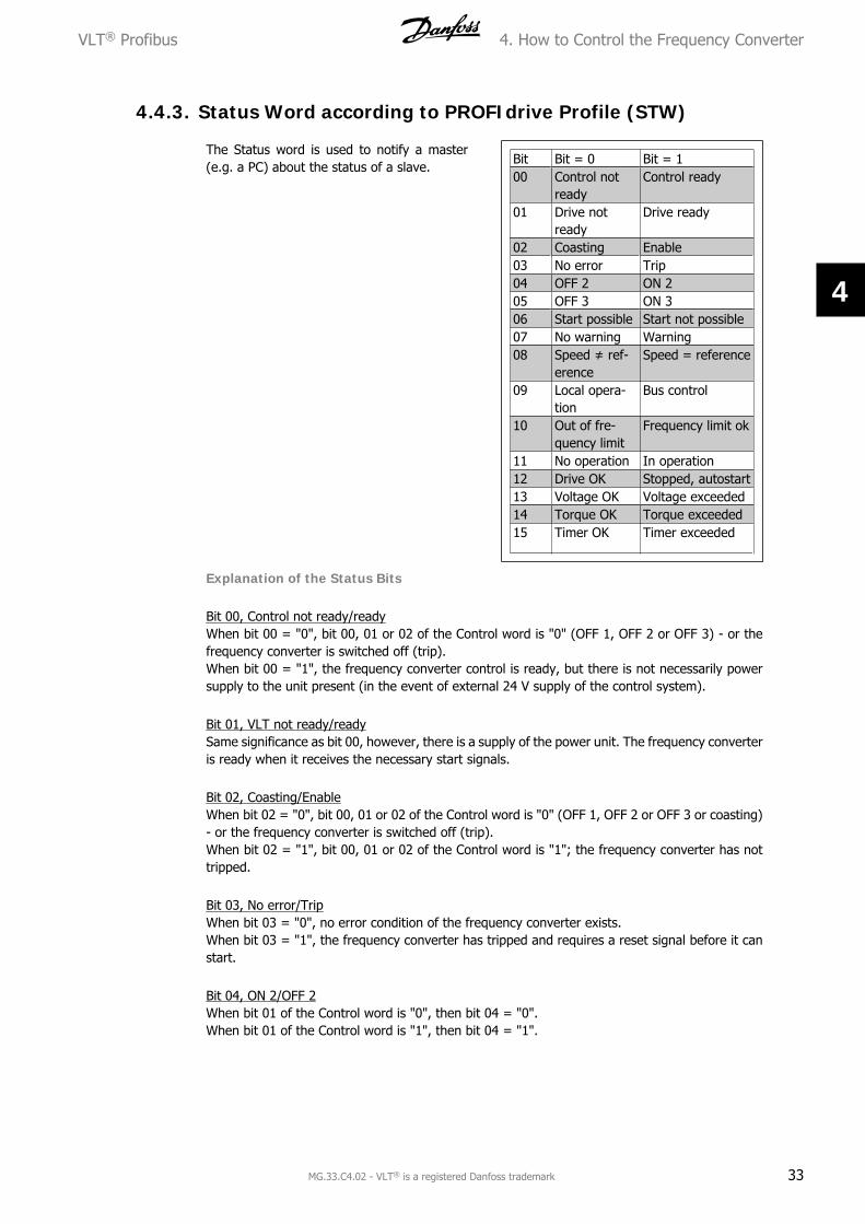
4.4.3. Status Word according to PROFIdrive Profile (STW)
The Status word is used to notify a master(e.g. a PC) about the status of a slave.
Bit Bit = 0 Bit = 100 Control not
readyControl ready
01 Drive notready
Drive ready
02 Coasting Enable03 No error Trip04 OFF 2 ON 205 OFF 3 ON 306 Start possible Start not possible07 No warning Warning08 Speed ≠ ref-
erenceSpeed = reference
09 Local opera-tion
Bus control
10 Out of fre-quency limit
Frequency limit ok
11 No operation In operation12 Drive OK Stopped, autostart13 Voltage OK Voltage exceeded14 Torque OK Torque exceeded15 Timer OK Timer exceeded
Explanation of the Status Bits
Bit 00, Control not ready/readyWhen bit 00 = "0", bit 00, 01 or 02 of the Control word is "0" (OFF 1, OFF 2 or OFF 3) - or thefrequency converter is switched off (trip).When bit 00 = "1", the frequency converter control is ready, but there is not necessarily powersupply to the unit present (in the event of external 24 V supply of the control system).
Bit 01, VLT not ready/readySame significance as bit 00, however, there is a supply of the power unit. The frequency converteris ready when it receives the necessary start signals.
Bit 02, Coasting/EnableWhen bit 02 = "0", bit 00, 01 or 02 of the Control word is "0" (OFF 1, OFF 2 or OFF 3 or coasting)- or the frequency converter is switched off (trip).When bit 02 = "1", bit 00, 01 or 02 of the Control word is "1"; the frequency converter has nottripped.
Bit 03, No error/TripWhen bit 03 = "0", no error condition of the frequency converter exists.When bit 03 = "1", the frequency converter has tripped and requires a reset signal before it canstart.
Bit 04, ON 2/OFF 2When bit 01 of the Control word is "0", then bit 04 = "0".When bit 01 of the Control word is "1", then bit 04 = "1".
VLT® Profibus 4. How to Control the Frequency Converter
MG.33.C4.02 - VLT® is a registered Danfoss trademark 33
4
Bit 05, ON 3/OFF 3When bit 02 of the Control word is "0", then bit 05 = "0".When bit 02 of the Control word is "1", then bit 05 = "1".
Bit 06, Start possible/Start not possibleIf PROFIdrive has been selected in par. 8-10 Control word profile, bit 06 will be "1" after a switch-off acknowledgement, after activation of OFF2 or OFF3, and after switching on the mains voltage.Start not possible will be reset, with bit 00 of the Control word being set to "0" and bit 01, 02 and10 being set to "1".
Bit 07, No warning/WarningBit 07 = “0” means that there are no warnings.Bit 07 = “1” means that a warning has occurred.
Bit 08, Speed ≠ reference / Speed = referenceWhen bit 08 = "0", the current speed of the motor deviates from the set speed reference value.This may occur, for example, when the speed is being changed during start/stop through rampup/down.When bit 08 = "1", the current speed of the motor corresponds to the set speed reference value.
Bit 09, Local operation/Bus controlBit 09 = "0" indicates that the frequency converter has been stopped by means of the stop buttonon the control panel, or that [Linked to hand] or [Local] has been selected in par. 3-13 Referencesite.When bit 09 = "1", the frequency converter can be controlled through the serial interface.
Bit 10, Out of frequency limit/Frequency limit OKWhen bit 10 = "0", the output frequency is outside the limits set in par. 4-11 Motor speed lowlimit (rpm) and par. 4-13 Motor speed high limit (rpm). When bit 10 = "1", the output frequencyis within the indicated limits.
Bit 11, No operation/OperationWhen bit 11 = "0", the motor does not turn.When bit 11 = "1", the frequency converter has a start signal, or the output frequency is higherthan 0 Hz.
Bit 12, Drive OK/Stopped, autostartWhen bit 12 = "0", there is no temporary overloading of the inverter.When bit 12 = "1", the inverter has stopped due to overloading. However, the frequency converterhas not switched off (trip) and will start again after the overloading has ended.
Bit 13, Voltage OK/Voltage exceededWhen bit 13 = "0", the voltage limits of the frequency converter are not exceeded.When bit 13 = "1", the direct voltage in the intermediate circuit of the frequency converter is toolow or too high.
Bit 14, Torque OK/Torque exceededWhen bit 14 = "0", the motor torque is below the limit selected in par. 4-16 Torque limit motormode and par. 4-17 Torque limit generator mode. When bit 14 = "1", the limit selected in par.4-16 Torque limit motor mode or par. 4-17 Torque limit generator mode is exceeded.
4. How to Control the Frequency Converter VLT® Profibus
34 MG.33.C4.02 - VLT® is a registered Danfoss trademark
4
Bit 15, Timer OK/Timer exceededWhen bit 15 = "0", the timers for the thermal motor protection and thermal frequency converterprotection have not exceeded 100%.When bit 15 = "1", one of the timers has exceeded 100%.
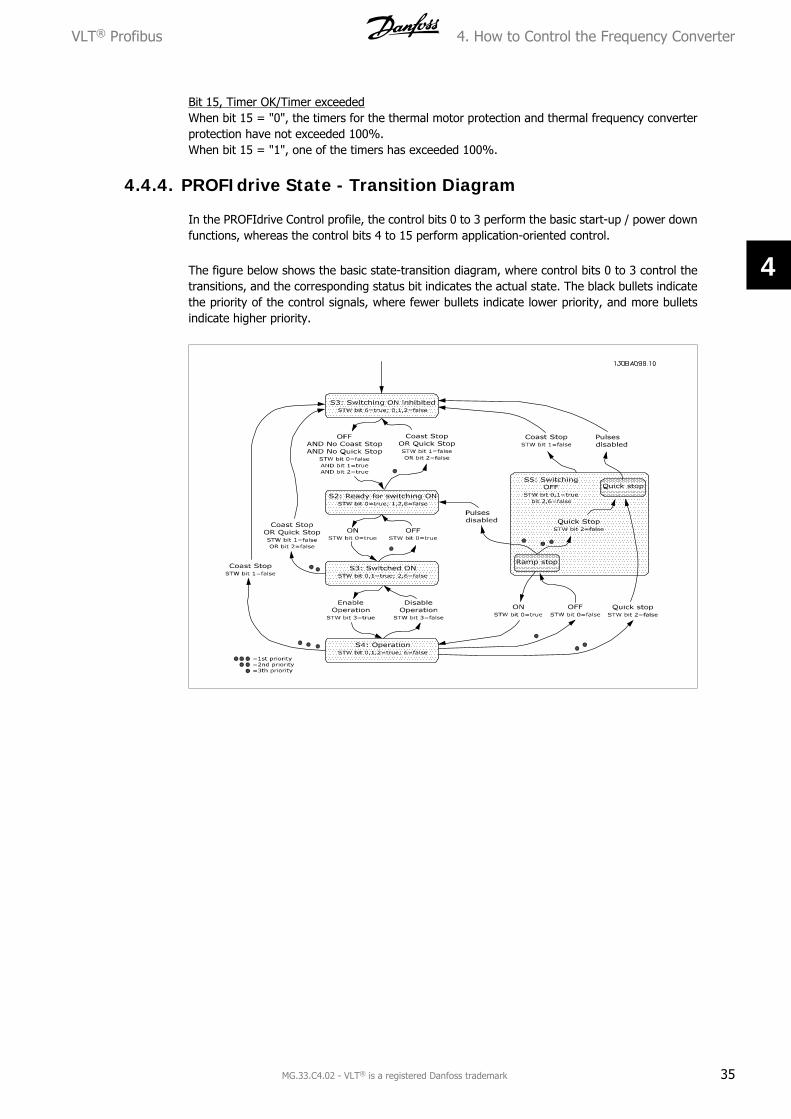
4.4.4. PROFIdrive State - Transition Diagram
In the PROFIdrive Control profile, the control bits 0 to 3 perform the basic start-up / power downfunctions, whereas the control bits 4 to 15 perform application-oriented control.
The figure below shows the basic state-transition diagram, where control bits 0 to 3 control thetransitions, and the corresponding status bit indicates the actual state. The black bullets indicatethe priority of the control signals, where fewer bullets indicate lower priority, and more bulletsindicate higher priority.
VLT® Profibus 4. How to Control the Frequency Converter
MG.33.C4.02 - VLT® is a registered Danfoss trademark 35
4
4.5. Danfoss FC Control Profile
4.5.1. Control Word according to FC Profile (CTW)
To select FC protocol in the control word, par. 8-10 Control word profile must be set to FC protocol[0]. The control word is used to send commands from a master (PLC or PC) to a slave (frequencyconverter).
Please refer to Application Examples for an example of a control word telegram using PPO type3.
Bit Bit value = 0 Bit value = 100 Reference value external selec-
tion lsb01 Reference value external selec-
tion msb02 DC brake Ramp03 Coasting No coasting04 Quick stop Ramp05 Hold output fre-
quencyUse ramp
06 Ramp stop Start07 No function Reset08 No function Jog09 Ramp 1 Ramp 210 Data invalid Data valid11 No function Relay 01 active12 No function Relay 04 active13 Parameter set-
upselection lsb
14 Parameter set-up
selection msb
15 No function Reverse
Explanation of the Control Bits
Bits 00/01 Reference valueBits 00 and 01 are used to choose between the four reference values, which are pre-programmedin par. 3-10 Preset reference according to the following table:
NB!In par. 8-56 Preset reference select a selection is made to define how Bit 00/01 gateswith the corresponding function on the digital inputs.
4. How to Control the Frequency Converter VLT® Profibus
36 MG.33.C4.02 - VLT® is a registered Danfoss trademark
4
Bit 02, DC brakeBit 02 = “0” leads to DC braking and stop. Braking current and duration are set in par. 2-01 DCBrake current and 2-02 DC Braking time. Bit 02 = “1” leads to ramping.
Bit 03, CoastingBit 03 = “0” causes the frequency converter to immediately "let go" of the motor (the outputtransistors are "shut off"), so that it coasts to a standstill.Bit 03 = “1” enables the frequency converter to start the motor if the other starting conditionshave been fulfilled.
NB!In par. 8-50 Coasting select a selection is made to define how Bit 03 gates with thecorresponding function on a digital input.
Bit 04, Quick stopBit 04 = “0” causes a stop, in which the motor speed is ramped down to stop via par. 3-81 Quickstop ramp time.
Bit 05, Hold output frequencyBit 05 = “0” causes the present output frequency (in Hz) to freeze. The frozen output frequencycan then be changed only by means of the digital inputs (par. 5-10 to 5-15) programmed to Speedup and Speed down.
NB!If Freeze output is active, the frequency converter can only be stopped by the fol-lowing:
• Bit 03 Coasting stop
• Bit 02 DC braking
• Digital input (par. 5-10 to 5-15) programmed to DC braking, Coastingstop or Reset and coasting stop.
Bit 06, Ramp stop/start:Bit 06 = “0” causes a stop, in which the motor speed is ramped down to stop via the selectedramp down parameter.Bit 06 = “1" permits the frequency converter to start the motor, if the other starting conditionshave been fulfilled.
NB!In par. 8-53 Start select a selection is made to define how Bit 06 Ramp stop/startgates with the corresponding function on a digital input.
Bit 07, ResetBit 07 = "0" does not cause a reset. Bit 07 = "1" causes the reset of a trip. Reset is activated onthe signal’s leading edge, i.e. when changing from logic "0" to logic "1".
Bit 08, JogBit 08 = "1" causes the output frequency to be determined by par. 3-19 Jog speed.
VLT® Profibus 4. How to Control the Frequency Converter
MG.33.C4.02 - VLT® is a registered Danfoss trademark 37
4
Bit 09, Selection of ramp 1/2Bit 09 = "0" means that ramp 1 is active (parameters 3-40 to 3-47). Bit 09 = "1" means that ramp2 (par. 3-50 to 3-57) is active.
Bit 10, Data not valid/Data validIs used to tell the frequency converter whether the control word is to be used or ignored. Bit 10= "0" causes the control word to be ignored, Bit 10 = "1" causes the control word to be used.This function is relevant, because the control word is always contained in the telegram, regardlessof which type of telegram is used, i.e. it is possible to turn off the control word if you do not wishto use it in connection with updating or reading parameters.
Bit 11, Relay 01Bit 11 = "0" Relay not activated. Bit 11 = "1" Relay 01 activated, provided Control word bit 11 hasbeen chosen in par. 5-40 Function relay.
Bit 12, Relay 04Bit 12 = "0" Relay 04 has not been activated. Bit 12 = "1" Relay 04 has been activated, providedControl word bit 12 has been chosen in par. 5-40 Function relay.
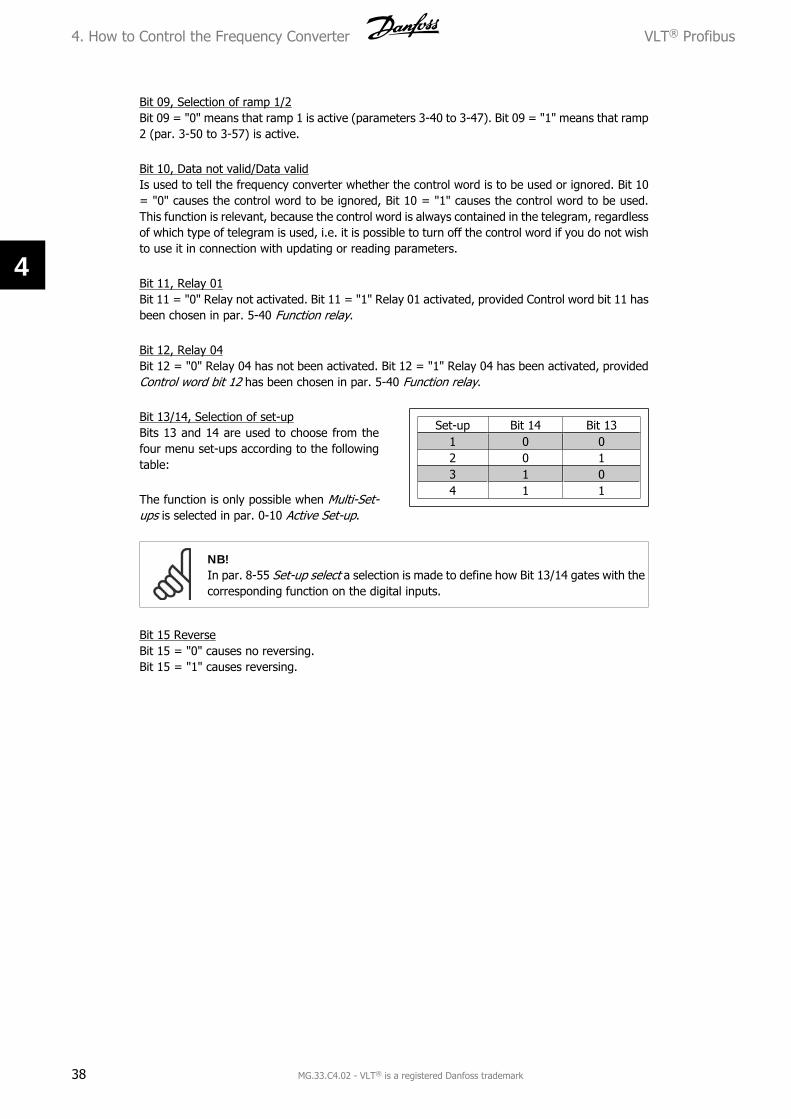
Bit 13/14, Selection of set-upBits 13 and 14 are used to choose from thefour menu set-ups according to the followingtable:
The function is only possible when Multi-Set-ups is selected in par. 0-10 Active Set-up.
Set-up Bit 14 Bit 131 0 02 0 13 1 04 1 1
NB!In par. 8-55 Set-up select a selection is made to define how Bit 13/14 gates with thecorresponding function on the digital inputs.
Bit 15 ReverseBit 15 = "0" causes no reversing.Bit 15 = "1" causes reversing.
4. How to Control the Frequency Converter VLT® Profibus
38 MG.33.C4.02 - VLT® is a registered Danfoss trademark
4
4.5.2. Status Word according to FC Profile (STW)
The status word is used to inform the master(e.g. a PC) of the operation mode of the slave(frequency converter).
Please refer to Application examples for anexample of a status word telegram using PPOtype 3.
Explanation of the Status Bits
Bit 00, Control not ready/readyBit 00 = "0" means that the frequency con-verter has tripped.Bit 00 = "1" means that the frequency con-verter controls are ready, but that the powercomponent is not necessarily receiving anypower supply (in case of external 24 V supplyto controls).
Bit 01, Drive readyBit 01 = "1". The frequency converter is readyfor operation, but there is an active coastingcommand via the digital inputs or via serialcommunication.
Bit 02, Coasting stopBit 02 = "0". The frequency converter has re-leased the motor.Bit 02 = "1". The frequency converter canstart the motor when a start command is giv-en.
Bit Bit = 0 Bit = 100 Control not
readyControl ready
01 Drive not ready Drive ready02 Coasting Enable03 No error Trip04 No error Error (no trip)05 Reserved -06 No error Triplock07 No warning Warning08 Speed ≠ refer-
enceSpeed = reference
09 Local operation Bus control10 Out of frequen-
cy limitFrequency limit ok
11 No operation In operation12 Drive OK Stopped, autostart13 Voltage OK Voltage exceeded14 Torque OK Torque exceeded15 Timer OK Timer exceeded
Bit 03, No error/tripBit 03 = "0" means that the frequency converter is not in fault mode.Bit 03 = "1" means that the frequency converter is tripped, and that a reset signal is required tore-establish operation.
Bit 04, No error/error (no trip)Bit 04 = "0" means that the frequency converter is not in fault mode.Bit 04 = “1” means that there is a frequency converter error but no trip.
Bit 05, Not usedBit 05 is not used in the status word.
Bit 06, No error / triplockBit 06 = "0" means that the frequency converter is not in fault mode.Bit 06 = “1” means that the frequency converter is tripped, and locked.
Bit 07, No warning/warningBit 07 = "0" means that there are no warnings.Bit 07 = "1" means that a warning has occurred.
VLT® Profibus 4. How to Control the Frequency Converter
MG.33.C4.02 - VLT® is a registered Danfoss trademark 39
4
Bit 08, Speed≠ reference/speed = referenceBit 08 = "0" means that the motor is running, but that the present speed is different from thepreset speed reference. It might, for example, be the case while the speed is being ramped up/down during start/stop.Bit 08 = "1" means that the present motor present speed matches the preset speed reference.
Bit 09, Local operation/bus controlBit 09 = "0" means that [STOP/RESET] is activated on the control unit, or that Local control inpar. 3-13 Reference site is selected. It is not possible to control the frequency converter via serialcommunication.Bit 09 = "1" means that it is possible to control the frequency converter via the fieldbus/ serialcommunication.
Bit 10, Out of frequency limitBit 10 = "0", if the output frequency has reached the value in par. 4-11 Motor speed low limit orpar. 4-13 Motor speed high limit.Bit 10 = "1" means that the output frequency is within the defined limits.
Bit 11, No operation/in operationBit 11 = "0" means that the motor is not running.Bit 11 = "1" means that the frequency converter has a start signal or that the output frequencyis greater than 0 Hz.
Bit 12, Drive OK/stopped, autostartBit 12 = "0" means that there is no temporary over temperature on the inverter.Bit 12 = "1" means that the inverter has stopped because of over temperature, but that the unithas not tripped and will resume operation once the over temperature stops.
Bit 13, Voltage OK/limit exceededBit 13 = "0" means that there are no voltage warnings.Bit 13 = "1" means that the DC voltage in the frequency converter’s intermediate circuit is too lowor too high.
Bit 14, Torque OK/limit exceededBit 14 = "0" means that the motor current is lower than the torque limit selected in par. 4-16Torque limit motor mode or par. 4-17 Torque limit generator mode.Bit 14 = "1" means that the torque limit in par. 4-16 and 4-17 has been exceeded.
Bit 15, Timer OK/limit exceededBit 15 = "0" means that the timers for motor thermal protection and VLT thermal protection,respectively, have not exceeded 100%.Bit 15 = "1" means that one of the timers has exceeded 100%.
4. How to Control the Frequency Converter VLT® Profibus
40 MG.33.C4.02 - VLT® is a registered Danfoss trademark
4
4.6. Synchronize and Freeze
The control commands SYNC/UNSYNC and FREEZE/UNFREEZE are broadcast functions.
SYNC/UNSYNC is used to synchronize control commands and/or speed reference to all the con-nected frequency converters.
FREEZE/UNFREEZE is used to freeze the status feedback in the slaves to get synchronized feed-back from all connected slaves.
The synchronize and freeze commands affect only process data (the PCD part of the PPO).
4.6.1. SYNC/UNSYNC
SYNC/UNSYNC can be used to obtain simultaneous reactions in several slaves, for examplesynchronized start, stop or speed change. A SYNC command will freeze the relevant control wordand speed reference. Incoming process data will be stored but not used until a new SYNC com-mand or a UNSYNC command is received.
An UNSYNC command stops the synchronisation mechanism and enables normal DP data ex-change.
4.6.2. FREEZE/UNFREEZE
FREEZE/UNFREEZE can be used for simultaneous reading of process data, for example outputcurrent, from several slaves.
A FREEZE command will freeze the actual values and upon request the slave will send back thevalue that was present when the FREEZE command was received.
Upon receipt of an UNFREEZE command the values will once again be continuously updated andthe slave will return a present value, i.e. a value generated by conditions at present time.
The values will be updated when a new FREEZE or UNFREEZE command is received.
VLT® Profibus 4. How to Control the Frequency Converter
MG.33.C4.02 - VLT® is a registered Danfoss trademark 41
4
5. How to Access the Parameters VLT® Profibus
42 MG.33.C4.02 - VLT® is a registered Danfoss trademark
5
5. How to Access the Parameters
5.1. Parameter Access in General
In an automated SYSTEM, frequency converter parameters can be accessed either from the proc-ess controller (i.e. PLC), or from various kinds of HMI equipment. For parameter access fromcontrollers and HMI, please observe the following:
FC 100, 200 and 300 parameters are located in four separate set-ups. Parameter access in thedrive is performed via several separated parameter channels, which can be used individually toaccess a certain parameter set-up. Select the desired set-up in par. 0-11 Edit set-up or 9-70Parameter set-up selection.
Using this mechanism it is possible to Read or Write to and from parameters in a certain set-upfrom a master class 1, e.g. a PLC, and simultaneously access parameters in a different set-up froma master class 2, e.g. a PC tool, without interfering with the set-up selection for the programmingsources.
Parameters can be accessed via the following sites:LCP on FC 100, 200 and 300FC Protocol on RS485 or USBCyclical data access on DP V0 (PCV Channel)PROFIBUS Master Class 1PROFIBUS Master Class 2 (3 connections possible)
Please note that although these parameter channels are separated, data conflict canoccur if write to parameters is made from a HMI unit into a set-up which is activelyin use by the frequency converter or the process controller (e.g. a PLC).
5.1.1. Data Store
Parameter write via the PCV channel (DP V0) will be stored in RAM only. If data has to be storedin Non Volatile Memory, the par. 9-71 PROFIBUS save data values can be used for storing one ormore set-ups.
Using DP V1 access, parameters can be stored either in RAM or Non-Volatile Memory by choiceof a specific Write Request command. Non-stored data can at any time be stored in non-volatilememory by activating par. 9-71 PROFIBUS save data values.
VLT® Profibus 5. How to Access the Parameters
MG.33.C4.02 - VLT® is a registered Danfoss trademark 43
5
5.1.2. Read / Write in Double Word Format, DP V1
Using the special Request IDs 0X51 (read) and 0X52 (write), it is possible to read and write to allparameters containing numeric values in a general format of Double Word. The value elementmust be right aligned and unused MSBs filled with zeros.
Example: Read of a parameter of type U8 will be transmitted as 00 00 00 xx, where xx is the valueto be transmitted. The data type signalled by the telegram will be 43h (dword).
Please refer to the table Request/ Response Attributes later in this chapter.
Access the parameters as follows:
5.1.3. PROFIBUS DP V1
Using the acyclic DP V1 transmission it is possible to read and write parameter values, as well asto read a number of descriptive attributes for each parameter. Access to parameters via DP V1 isdescribed in the DP V1 Parameter Access section.
5.1.4. PROFIBUS DP V0 / PCV Channel
Parameter access via the PCV channel is performed using PROFIBUS DP V0 cyclic data exchange,where the PCV channel is part of the PPOs described in the PPO Types section. Using the PCVchannel, it is possible to read and write parameter values, as well as read a number of descriptiveattributes for each parameter. The functionality of the PCV channel is described in the PCV Pa-rameter Access section.
NB!Object and data types supported by FC 100, 200 and 300 and common to both DPV1 and PCV parameter access are listed in the Parameters chapter.
5.2. DP V1 Parameter Access
This section is useful for the developer with some experience in:PLC programs with PROFIBUS master class 1 functionalityPC applications with PROFIBUS master class 2 functionality
For more detailed instructions in use of the DP V1 function in FC 100, 200 and 300, please referto the Operating Instructions MG.90.EX.YY Information about the features supported by the PRO-FIBUS DP V1 functions.
5.2.1. PROFIBUS DP V1 Introduction
The PROFIBUS DP extension DPV1 offers acyclical communication in addition to the cyclical datacommunication of DP V0. This feature is possible using a DP master class 1 (e.g. PLC), as well asa DP master class 2 (e.g. PC Tool).
Cyclical communication means that data transfer takes place continuously with a certain refreshrate. This is the known DP V0 function normally used for quick update of I/O Process Data.
5. How to Access the Parameters VLT® Profibus
44 MG.33.C4.02 - VLT® is a registered Danfoss trademark
5
Acyclical communication takes the form of a once-off data transfer event, mainly used for Read /Write from and to parameters from process controllers, PC-based tools or monitoring SYSTEMs.
5.2.2. Features of a Master Class 1 Connection
- Cyclical data exchange (DP V0)
- Acyclical read/write from and to parameters
In general a master class 1 is used as the process controller (either PLC or PC-based), responsiblefor commands, speed reference, status of the application, etc.. The master class 1 acyclical con-nection can be used for general parameter access in the slaves. However, the acyclical connectionis fixed, and cannot be changed during operation.
5.2.3. Features of a Master Class 2 Connection
- Initiate / Abort acyclical connection
- Acyclical read/write from and to parameters
The master class 2 acyclical connection is typically used for configuration or commissioning toolsfor easy access to each parameter in any slave in the SYSTEM. The acyclical connection can bedynamically established (Initiate) or removed (Abort) even when a master class 1 is active on thenetwork.
5.2.4. Services Overview for FC 100, 200 and 300
Master type ServiceRead Write Data trans-
portInitiate Abort Alarm
read datafrom slave
write datato slave
read andwrite data
open aconnection
close a con-nection
Master Class 1 yes yes yes - - -Master Class 2 yes yes yes yes yes -
5.2.5. Principle of Data Exchange by PROFIBUS DP V1
In a DP cycle the master class 1 (MC1) will first update the cyclical process data for all slaves inthe SYSTEM. The MC1 can then send one acyclical message to one slave. If a master class 2 (MC2)is connected, the MC1 will hand over the bus rights to MC2, which will then be permitted to sendone acyclical message to one slave. The token is then handed back to the MC1, and a new DPcycle begins.
VLT® Profibus 5. How to Access the Parameters
MG.33.C4.02 - VLT® is a registered Danfoss trademark 45
5
MC : Master Class
C1...Cn: Cyclical data
AC1: Acyclical data Master Class 1
AC2: Acyclical data Master Class 2
PROFIBUS DP services are activated via specific Service Access Points (SAP). For acyclical com-munication, the following SAP are specified:
Master SAP Slave SAP Meaning50 (32H) 49 (31H) Master Class 2: Initiate request50 (32H) 0..48 (0..30H) Master Class 2: Abort, Read, Write, Data transfer51 (33H) 50, 51 (32H, 33H) Master Class 2: Alarm51 (33H) 51 (33H) Master Class 2: Read, Write
5.2.6. How to Use the DP V1 Features for Parameter Access
This section describes how DP V1 can be used for accessing VLT parameters.
For units as complex as frequency converters, the standard PROFIBUS DP V1 read and writeservices are not sufficient for accessing the many parameters and attributes in the drive. For thisreason, the PROFIdrive Parameter Channel is defined. Using this parameter Read/Write is per-formed by addressing a single DP V1 object in the frequency converter, in the following way:Slot = 0Index = 47
The telegram has the following general structure:
PROFIBUSTelegramHeader
Data Unit PROFIBUSTelegramTrailer
DP V1Command/response
PROFIdrive V3.0 Parameter Channel
DU0
DU1
DU2
DU3
Req. / Res. Header Data
The DP V1 command/response part is used for the standard DP V1 read/Write on the Slot 0, Index47 data block.
The PROFIdrive V3 Parameter Channel is used to access specific parameter data in the VLT.
5. How to Access the Parameters VLT® Profibus
46 MG.33.C4.02 - VLT® is a registered Danfoss trademark
5
For a detailed description of the DP V1 command handling, please refer to the PROFIBUS DP V1Design Guide, ref. MG.90.EX.YY.
5.2.7. DP V1 Read / Write Services
The table below shows the content of the DP V1 command / Response headers and their possibleattributes.
DU Byte Value Meaning Specified0 Function number
0x48Idle REQ, RES
0x51 Data transport REQ, RES0x56 Resource Manager REQ 0x57 Initiate REQ, RES0x58 Abort REQ 0x5C Alarm REQ, RES0x5E Read REQ, RES 0x5F Write REQ, RES0xD1 Data transport negative response 0xD7 Initiate negative response0xDC Alarm negative response 0xDE Read negative response0xDF Write negative response
1 Always zero Slot number DPV12 47 Index DPV13 xx Data length DPV14..n User data PNO Drive Profile V3.0
VLT® Profibus 5. How to Access the Parameters
MG.33.C4.02 - VLT® is a registered Danfoss trademark 47
5
5.2.8. How to Use the DP V1 Acyclical Parameter Channel
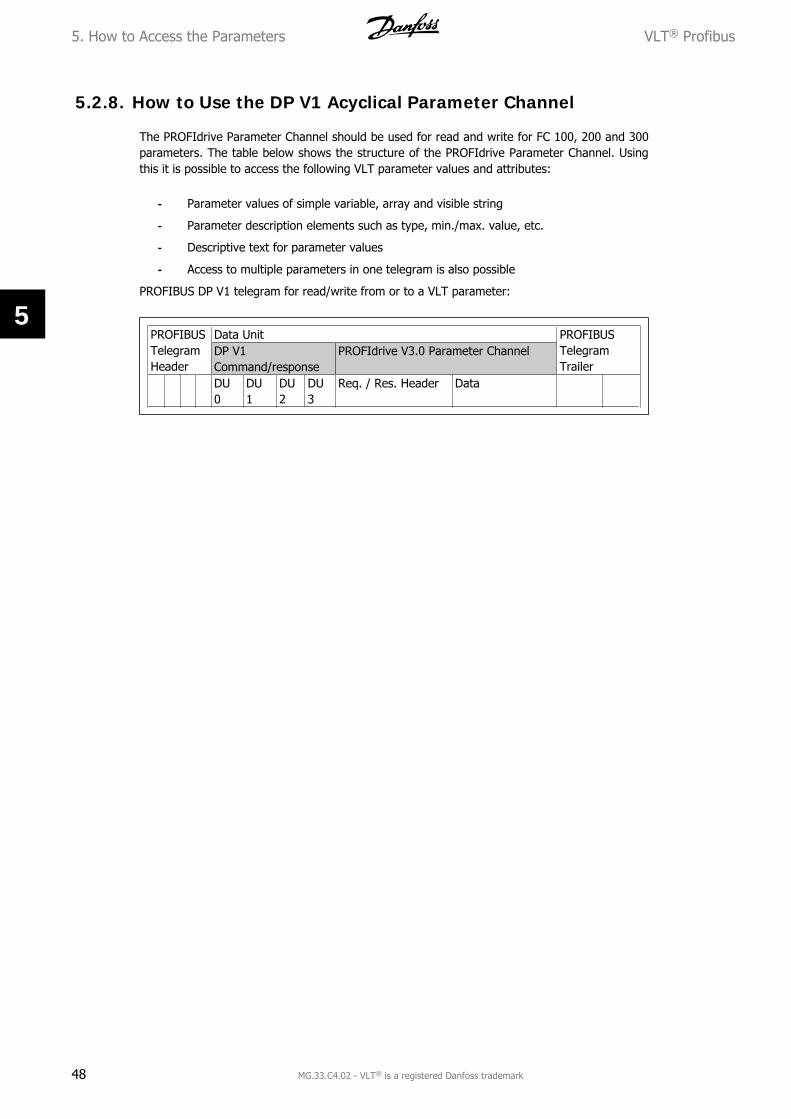
The PROFIdrive Parameter Channel should be used for read and write for FC 100, 200 and 300parameters. The table below shows the structure of the PROFIdrive Parameter Channel. Usingthis it is possible to access the following VLT parameter values and attributes:
- Parameter values of simple variable, array and visible string
- Parameter description elements such as type, min./max. value, etc.
- Descriptive text for parameter values
- Access to multiple parameters in one telegram is also possible
PROFIBUS DP V1 telegram for read/write from or to a VLT parameter:
PROFIBUSTelegramHeader
Data Unit PROFIBUSTelegramTrailer
DP V1Command/response
PROFIdrive V3.0 Parameter Channel
DU0
DU1
DU2
DU3
Req. / Res. Header Data
5. How to Access the Parameters VLT® Profibus
48 MG.33.C4.02 - VLT® is a registered Danfoss trademark
5
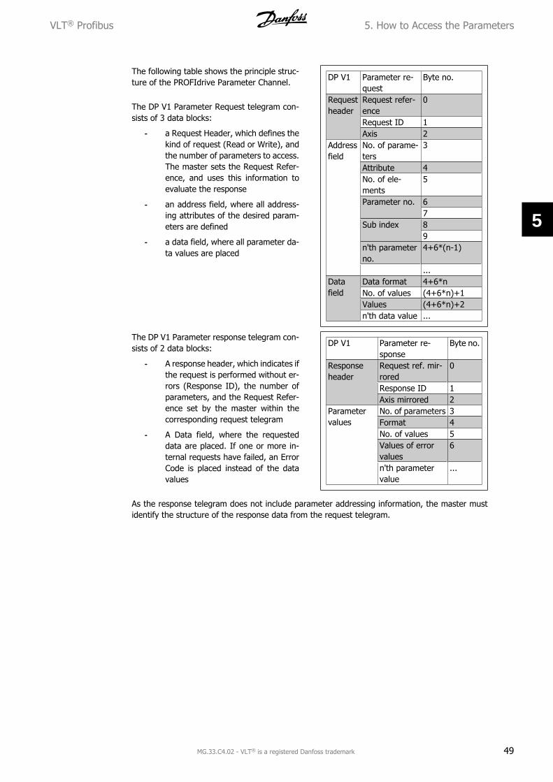
The following table shows the principle struc-ture of the PROFIdrive Parameter Channel.
The DP V1 Parameter Request telegram con-sists of 3 data blocks:
- a Request Header, which defines thekind of request (Read or Write), andthe number of parameters to access.The master sets the Request Refer-ence, and uses this information toevaluate the response
- an address field, where all address-ing attributes of the desired param-eters are defined
- a data field, where all parameter da-ta values are placed
DP V1 Parameter re-quest
Byte no.
Requestheader
Request refer-ence
0
Request ID 1Axis 2
Addressfield
No. of parame-ters
3
Attribute 4No. of ele-ments
5
Parameter no. 67
Sub index 89
n'th parameterno.
4+6*(n-1)
...Datafield
Data format 4+6*nNo. of values (4+6*n)+1Values (4+6*n)+2n'th data value ...
The DP V1 Parameter response telegram con-sists of 2 data blocks:
- A response header, which indicates ifthe request is performed without er-rors (Response ID), the number ofparameters, and the Request Refer-ence set by the master within thecorresponding request telegram
- A Data field, where the requesteddata are placed. If one or more in-ternal requests have failed, an ErrorCode is placed instead of the datavalues
DP V1 Parameter re-sponse
Byte no.
Responseheader
Request ref. mir-rored
0
Response ID 1Axis mirrored 2
Parametervalues
No. of parameters 3Format 4No. of values 5Values of errorvalues
6
n'th parametervalue
...
As the response telegram does not include parameter addressing information, the master mustidentify the structure of the response data from the request telegram.
VLT® Profibus 5. How to Access the Parameters
MG.33.C4.02 - VLT® is a registered Danfoss trademark 49
5
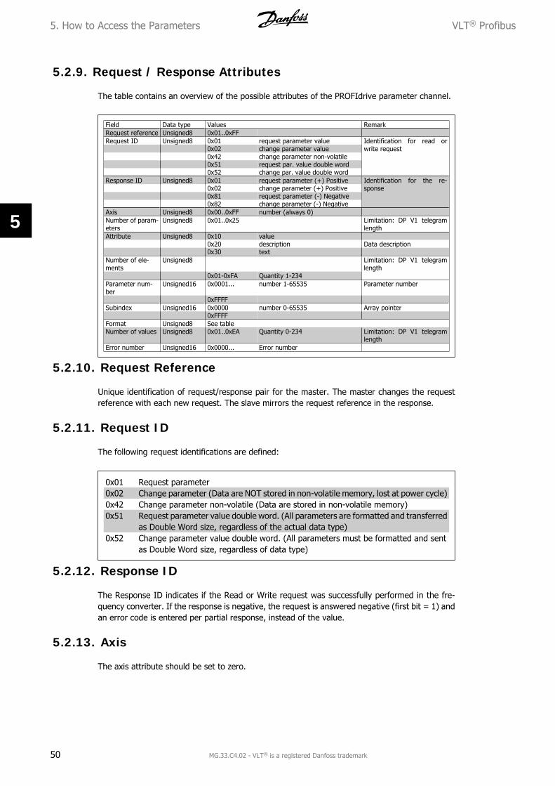
5.2.9. Request / Response Attributes
The table contains an overview of the possible attributes of the PROFIdrive parameter channel.
Field Data type Values RemarkRequest reference Unsigned8 0x01..0xFF Request ID Unsigned8 0x01 request parameter value Identification for read or
write request0x02 change parameter value0x42 change parameter non-volatile0x51 request par. value double word0x52 change par. value double word
Response ID Unsigned8 0x01 request parameter (+) Positive Identification for the re-sponse 0x02 change parameter (+) Positive
0x81 request parameter (-) Negative 0x82 change parameter (-) NegativeAxis Unsigned8 0x00..0xFF number (always 0)Number of param-eters
Attribute Unsigned8 0x10 value0x20 description Data description0x30 text
Number of ele-ments
Unsigned8 Limitation: DP V1 telegramlength
0x01-0xFA Quantity 1-234Parameter num-ber
Unsigned16 0x0001... number 1-65535 Parameter number
0xFFFFSubindex Unsigned16 0x0000 number 0-65535 Array pointer 0xFFFF Format Unsigned8 See tableNumber of values Unsigned8 0x01..0xEA Quantity 0-234 Limitation: DP V1 telegram
lengthError number Unsigned16 0x0000... Error number
5.2.10. Request Reference
Unique identification of request/response pair for the master. The master changes the requestreference with each new request. The slave mirrors the request reference in the response.
5.2.11. Request ID
The following request identifications are defined:
0x01 Request parameter0x02 Change parameter (Data are NOT stored in non-volatile memory, lost at power cycle)0x42 Change parameter non-volatile (Data are stored in non-volatile memory)0x51 Request parameter value double word. (All parameters are formatted and transferred
as Double Word size, regardless of the actual data type)0x52 Change parameter value double word. (All parameters must be formatted and sent
as Double Word size, regardless of data type)
5.2.12. Response ID
The Response ID indicates if the Read or Write request was successfully performed in the fre-quency converter. If the response is negative, the request is answered negative (first bit = 1) andan error code is entered per partial response, instead of the value.
5.2.13. Axis
The axis attribute should be set to zero.
5. How to Access the Parameters VLT® Profibus
50 MG.33.C4.02 - VLT® is a registered Danfoss trademark
5
5.2.14. Number of Parameters
For multi-parameter requests specifying the number of the Parameter Address and/or ParameterValue areas. For a single request the number is 1.
5.2.15. Attribute
The attribute determines which kind of data to access. The frequency converter will respond tothe attributes Value (10H), Description (20H) and Text (30H).
5.2.16. Attribute Value (10H)
The attribute value permits reading or writing of parameter values.
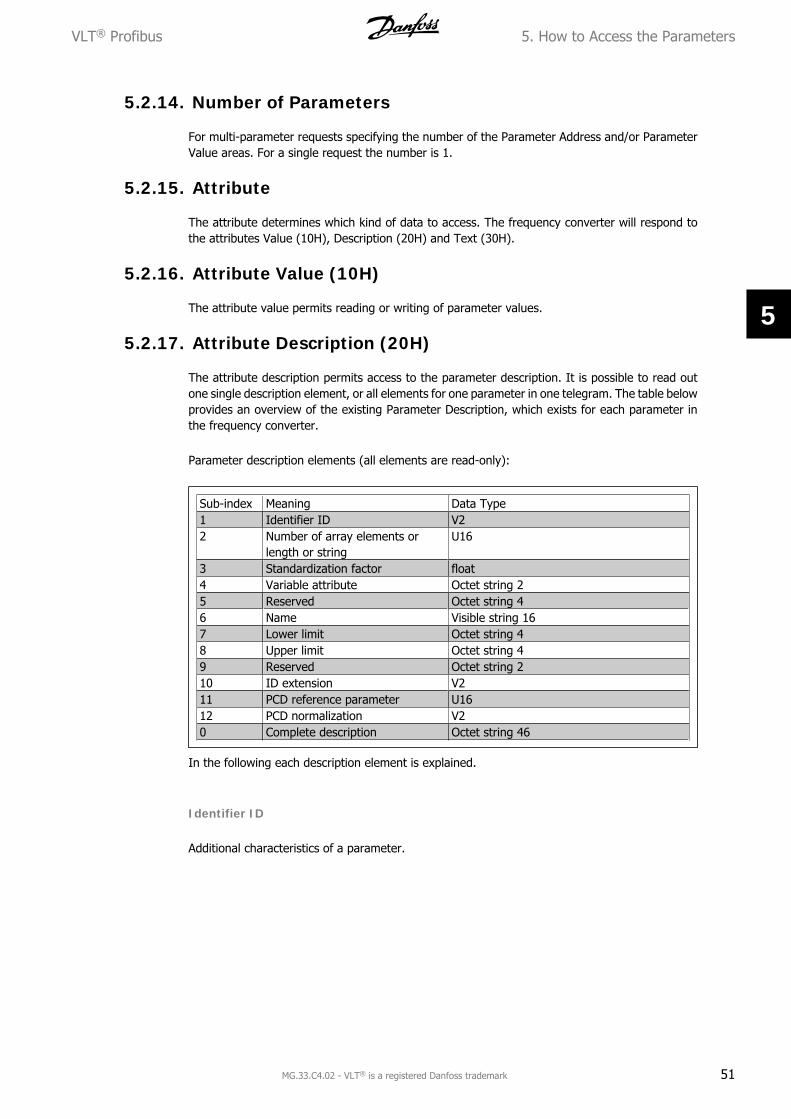
5.2.17. Attribute Description (20H)
The attribute description permits access to the parameter description. It is possible to read outone single description element, or all elements for one parameter in one telegram. The table belowprovides an overview of the existing Parameter Description, which exists for each parameter inthe frequency converter.
Parameter description elements (all elements are read-only):
Sub-index Meaning Data Type1 Identifier ID V22 Number of array elements or
In the following each description element is explained.
Identifier ID
Additional characteristics of a parameter.
VLT® Profibus 5. How to Access the Parameters
MG.33.C4.02 - VLT® is a registered Danfoss trademark 51
5
Bit Meaning15 Reserved14 Array13 Parameter value can be reset only12 Parameter has been changed from
factory setting11 Reserved10 Additional text array available9 Parameter is read-only8 Standardizaton factor and variable
attribute not relevant0-7 Data type
Number of Array Elements
Contains the number of array elements, if the parameter is an array; the string length, if theparameter value is a string; or 0 if the parameter is neither.
Standardization Factor
Conversion factor for scaling a given parameter value to standard SI units.For example, if the given value is in mV, the standardization factor will be 1000, which convertsthe given value to V.The standardization factor is in Float format.
Variable Attribute
Consists of 2 bytes. The first byte contains the variable index, which defines the physical unit ofthe parameter (e.g. Ampere, Volt).The second byte is the conversion index, which is a scaling factor for the parameter. In generalall parameters accessible by PROFIBUS are organized and transmitted as real numbers. The con-version index defines a factor for conversion the actual value to a standard physical unit. (aconversion index of -1 means, that the actual value must be divided by 10 to become a standardphysical unit e.g.. Volt.
Name
Contains the parameter name, limited to 16 characters, e.g. “LANGUAGE” for parameter 1. Thistext is available in the language selected in par 1.
Lower Limit
Contains the minimum value of the parameter. Format is 32 bit signed.
Upper Limit
Contains the maximum value of the parameter. Format is 32 bit signed.
5. How to Access the Parameters VLT® Profibus
52 MG.33.C4.02 - VLT® is a registered Danfoss trademark
5
ID Extension
Not supported
PCD Reference Parameter
Process data may be scaled by a parameter, e.g. the max reference of 0x4000 (in %) dependson the setting of parameter “X”.To enable the master to calculate the “real” value of the process data, it has to know the valueof parameter “X”, and therefore the process data must deliver a reference to parameter “X”.
Field PCD Normalization
The field PCD normalization must express, in any case, the value that represents the 100 %, i.e.the normalization delivered back must be the set bit 15 and a value of 0xe (14, 214 = 0x4000),and the result must be 0x800e.
Complete Description
Returns the complete parameter description with the fields 1 to 12 in order. Length = 46 byte.
5.2.18. Attribute Text (30H)
For some frequency converter parameters a descriptive text is available, which can be read usingthis attribute. The availability of a text description for a parameter is indicated by a bit set in theIdentifier (ID) Parameter Description element, which can be read out by the Description Attribute(20H) sub-index = 1. If bit 10 is set, a descriptive text exists for each value of the parameter.As an example, par. 0-01 Language has settings from 0 to 5. For each of these values a specifictext exists: 0 = ENGLISH, 2 = DEUTSCH, etc.
5.2.19. Format
Specifies the format type for each parameter (word, byte, etc.), see below.
VLT® Profibus 5. How to Access the Parameters
MG.33.C4.02 - VLT® is a registered Danfoss trademark 53
5
5.2.20. Supported data types
Value Data Type3 Integer164 Integer325 Unsigned86 Unsigned167 Unsigned329 Visible string10 Octet string (byte string)33 N2 (standardised value)35 V2 (bit sequence)44 Error54 Time difference without date in-
dication
5.2.21. Value
The value field contains the parameter value of the request. When the response is negative, thefield contains a corresponding error code. If the values consist of an odd number of bytes, a zerobyte is appended in order to maintain the word structure of the telegrams.
For a positive partial response, the parameter value field contains the following attributes:Format = (Data Type or Byte, Word, Double Word)Number of values = actual number of valuesValue = Parameter value
For a negative partial response, the parameter value field contains the following:Format = error (44H)Number of values = 1Value = error value = error number
5.2.22. Error Number for Drive Profile V3.0
When the parameter request is invalid, the frequency converter will return a corresponding errorcode. The table below lists the full range of error codes.
Error codes for DP V1 parameter requests
5. How to Access the Parameters VLT® Profibus
54 MG.33.C4.02 - VLT® is a registered Danfoss trademark
5
Error code Meaning Additional Info0x00 Unknown parameter 00x01 Parameter is read-only sub-index0x02 Value out of range due to max/min value sub-index0x03 Wrong sub-index sub-index0x04 Parameter is no array 00x05 Wrong data type (wrong data length) 00x06 This parameter may not be set, only reset sub-index0x07 Descriptive element is read-only sub-index0x09 No description available (only value) 00x0b Process control not possible 00x0f No text array available (only value) 00x11 Not possible in current state 00x14 Value out of range due to drive state/configuration sub-index0x15 Reply too long (more than 240 bytes) 00x16 Wrong parameter address (unknown or unsupported value for
attribute, element, par. number or sub-index or illegal combi-nation)
0
0x17 Illegal format (for writing) 00x18 Value amount not consistent 00x65 Wrong axis: action not possible with this axis -0x66 Unknown service request -0x67 This service is not possible with multi parameter access -0x68 Parameter value can not be read from bus -
VLT® Profibus 5. How to Access the Parameters
MG.33.C4.02 - VLT® is a registered Danfoss trademark 55
5
5.3. PCV Parameter Access
Parameter access via the PCV channel is performed by the PROFIBUS DP V0 cyclical data ex-change, where the PCV channel is part of the PPOs described in the chapter How to Control theFrequency Converter.
PCV: Parameter Characteristics ValuePCD: Process DataPCA: Parameter Characteristics (Bytes 1, 2)IND: Sub index (Byte 3. Byte 4 is not used)PVA: Parameter value (Bytes 5 to 8)CTW: Control wordSTW: Status wordMRV: Main reference valueMAV: Main actual value (Actual output frequency)
Using the PCV channel it is possible to read and write parameter values, as well as readout of anumber of describing attributes of each parameter.
5.3.1. PCA Handling
The PCA part of PPO types 1, 2 and 5 can handle several tasks. The master can control andsupervise parameters and request a response from the slave, whereas the slave can respond toa request from the master.Requests and responses is a handshake procedure and cannot be batched, meaning that if themaster sends out a read/write request, it has to wait for the response, before it sends a newrequest. The request or response data value will be limited to maximum 4 bytes, which impliesthat text strings are not transferable. For further information, please see the Application Exampleschapter.
56 MG.33.C4.02 - VLT® is a registered Danfoss trademark
5
5.3.3. Request / Response Handling
The RC portion of the PCA word defines the requests that may be issued from the master to theslave as well as what other portions of the PCV (IND and PVA) are involved. The PVA portion willtransmit word-size parameter values in bytes 7 and 8, while long word size values require bytes5 to 8 (32 bits). If the Response / Request contains array elements, the IND will carry the ArraySub-index. If parameter descriptions are involved, the IND will hold the Record Sub-index of theparameter description.
5.3.4. RC Content
Request Function0 No request1 Request parameter value2 Change parameter value (word)3 Change parameter value (long
word)4 Request description element5 Change description element6 Request parameter value (array)7 Request parameter value (array
word)8 Request parameter value (array long
word)9 Request number of array elements10-15 Not used
If the slave rejects a request from the master,the RC word in the PPO-read will indicate thisby assuming the value 7. The fault number willbe carried by bytes 7 and 8 in the PVA ele-ment.
Re-sponse
Function
0 No response1 Transfer parameter value (word)2 Transfer parameter value (long
word)3 Transfer description element4 Transfer parameter value (array
word)5 Transfer parameter value (array long
word)6 Transfer number of array elements7 Request rejected (incl. fault #, see
below)8 Not serviceable by PCV interface9 Not used10 Not used11 Not used12 Not used13-15 Not used
VLT® Profibus 5. How to Access the Parameters
MG.33.C4.02 - VLT® is a registered Danfoss trademark 57
5
Faultno.
Interpretation
0 Illegal PNU1 Parameter value cannot be changed2 Upper or lower limit exceeded3 Subindex corrupted4 No array5 Data type false6 Cannot be set by user (reset only)7 Description element cannot be changed8 IR required PPO-write not available9 Description data not available10 Access group11 No parameter write access12 Key word missing13 Text in cyclical transmission not readable14 Name in cyclical transmission not reada-
ble15 Text array not available16 PPO-write missing17 Request temporarily rejected18 Other fault19 Data in cyclical transmission not readable130 There is no bus access to the parameter
called131 Data change is not possible because fac-
tory setup has been selected
5. How to Access the Parameters VLT® Profibus
58 MG.33.C4.02 - VLT® is a registered Danfoss trademark
5
5.3.5. Example
This example shows how to use PPO type 1 to change the ramp-up time (parameter 3-41 Ramp1 ramp up time) to 10 seconds and to command a start and speed reference of 50%.
Frequency converter parameter settings:Par. 8-50 Coasting select: BusPar. 8-10 Control word profile: PROFIdrive profile
5.3.6. PCV
PCA – Parameter Characteristics
PCA part (byte 1-2).The RC part tells what the PCV part must be used for. The functions available appear from thetable, see PCA handling.
When a parameter is to be changed, choose value 2 or 3. In this example 3 is chosen, becausepar. 3-41 Ramp 1 ramp up time covers a long word (32 bits).Par. 3-41 = 155 hex: In this example byte 1 and 2 are set to 3155.
IND (bytes 3-4):Used when reading/changing parameters with sub-index, for example par. 9-15 PCD write con-figuration. In the example bytes 3 and 4 are set to 00 Hex.
PVA (bytes 5-8):The data value of par. 3-41 Ramp 1 ramp up time must be changed to 10.00 seconds. The valuetransmitted must be 1000, because the conversion index for par. 3-41 Ramp 1 ramp up time is –2. This means that the value received by the frequency converter is divided by 100, such that thefrequency converter perceives 1000 as 10.00. Bytes 5-8 = 1000 = 03E8 Hex. See Object and Datatypes supported.
5.3.7. PCD
Control word (CTW) according to PROFIdrive profile:Control words consist of 16 bits. The meaning of the each bit is explained in the section Controlword and Status word. The following bit pattern sets all necessary start commands:0000 0100 0111 1111 = 047F Hex.*0000 0100 0111 1110 = 047E Hex.*0000 0100 0111 1111 = 047F Hex.Quick stop: 0000 0100 0110 1111 = 046F Hex.Stop: 0000 0100 0011 1111 = 043F Hex.
NB!* For restart after power up: Bit 1 and 2 of the CTW must be set to “1” and bit 0toggled from “0” to “1”.
5.3.8. MRV
Speed reference, the data format is "Standar-dized value". 0 Hex = 0% and 4000 Hex =100%.
In the example, 2000 Hex is used, corre-sponding to 50% of maximum frequency (par.3-03Max. Reference).
VLT® Profibus 5. How to Access the Parameters
MG.33.C4.02 - VLT® is a registered Danfoss trademark 59
5
The whole PPO therefore has the followingvalues in Hex:
60 MG.33.C4.02 - VLT® is a registered Danfoss trademark
5
The process data within the PCD part acts im-mediately upon the frequency converter, andcan be updated from the master as quickly aspossible. The PCV part is a "handshake" pro-cedure which means that the frequency con-verter has to acknowledge the command,before a new one can be written.
A positive response to the above example maylook like this:
The PCD part responds according to the state and parameterisation of the frequency converter.The PCV part responds as:- PCA: As the request telegram, but here the RC part is taken from the response table, see thePCA handling section. In this example RC is 2 Hex, which is a confirmation that a parameter valueof the type long word (32 bit) has been transferred. IND is not used in this example.- PVA: 03E8Hex in the PVA part tells that the value of par. 3-41 Ramp 1 ramp up time is 1000,which corresponds to 10.00.- STW: 0F07 Hex means that the motor is running and there are no warnings or faults (for detailssee the Status word table in the Status word section).- MAV: 2000 Hex indicates that the output frequency is 50% of the maximum reference.
RC is 7 Hex, which means that the request has been rejected, and the fault number can be foundin the PVA part. In this case the fault number is 2, which means that the upper or lower limit ofthe parameter is exceeded. See the fault number table in the PCA handling section.
VLT® Profibus 5. How to Access the Parameters
MG.33.C4.02 - VLT® is a registered Danfoss trademark 61
5
6. Parameters VLT® Profibus
62 MG.33.C4.02 - VLT® is a registered Danfoss trademark
6
6. Parameters
8-01 Control Site
Option: Function:
[0] * Digital and ctrl. word Control by using both digital input and control word.
[1] Digital only Control by using digital inputs only.
[2] Control word only Control by using control word only.
The setting in this parameter overrides the settings in par. 8-50 to 8-56.
8-02 Control Word Source
Option: Function:
[0] None
[1] FC RS485
[2] FC USB
[3] Option A
[4] Option B
[5] Option C0
[6] Option C1
[30] External Can Select the source of the control word: one of two serial interfa-ces or four installed options. During initial power-up, the fre-quency converter automatically sets this parameter to OptionA [3] if it detects a valid fieldbus option installed in slot A. If theoption is removed, the frequency converter detects a change inthe configuration, sets par. 8-02 back to default setting FCRS485, and the frequency converter then trips. If an option isinstalled after initial power-up, the setting of par. 8-02 will notchange but the frequency converter will trip and display: Alarm67 Option Changed.This parameter cannot be adjusted while the motor is running.
8-03 Control Word Timeout Time
Range: Function:
1.0s* [0.1 - 18000.0 s] Enter the maximum time expected to pass between the recep-tion of two consecutive telegrams. If this time is exceeded, itindicates that the serial communication has stopped. The func-tion selected in par. 8-04 Control Word Time-out Function willthen be carried out. The time-out counter is triggered by a validcontrol word.
8-04 Control Word Timeout Function
Option: Function:
[0] * Off
[1] Freeze Output
[2] Stop
VLT® Profibus 6. Parameters
MG.33.C4.02 - VLT® is a registered Danfoss trademark 63
6
[3] Jogging
[4] Max. Speed
[5] Stop and trip
[7] Select set-up 1
[8] Select set-up 2
[9] Select set-up 3
[10] Select set-up 4 Select the time-out function. The time-out function activateswhen the control word fails to be updated within the time periodspecified in par. 8-03 Control Word Time-out Time.
- Off [0]: Resume control via serial bus (Fieldbus orstandard) using the most recent control word.
- Freeze output [1]: Freeze output frequency until com-munication resumes.
- Stop [2]: Stop with auto restart when communicationresumes.
- Jogging [3]: Run the motor at JOG frequency untilcommunication resumes.
- Max. freq. [4]: Run the motor at maximum frequencyuntil communication resumes.
- Stop and trip [5]: Stop the motor, then reset the fre-quency converter in order to restart: via the fieldbus,via the reset button on the LCP or via a digital input.
- Select set-up 1-4 [7] - [10]: This option changes theset-up upon reestablishment of communication follow-ing a control word time-out. If communication resumescausing the time-out situation to disappear, par. 8-05End-of-time-out Function defines whether to resumethe set-up used before the time-out or to retain theset-up endorsed by the time-out function. Note thefollowing configuration required in order to change theset-up after a time-out: Set Par. 0-10 Active set-up toMulti set-up [9], and select the relevant link in par.0-12 This Set-up Linked To.
8-05 End-of-Timeout Function
Option: Function:
Select the action after receiving a valid control word following atime-out. This parameter is active only when par. 8-04 is set to[Set-up 1-4].
[0] Hold set-up Retains the set-up selected in par. 8-04 and displays a warning,until par. 8-06 toggles. Then the frequency converter resumesits original set-up.
[1] * Resume set-up Resumes the set-up active prior to the time-out.
8-06 Reset Control Word Timeout
Option: Function:
[0] * Do not reset
6. Parameters VLT® Profibus
64 MG.33.C4.02 - VLT® is a registered Danfoss trademark
6
[1] Do reset Select Do reset [1] to return the frequency converter to theoriginal set-up following a control word time-out. When the val-ue is set to Do reset [1], the frequency converter performs thereset and then immediately reverts to the Do not reset [0] set-ting.Select Do not reset [0] to retain the set-up specified in par. 8-04,Select setup 1-4 following a control word time-out.This parameter is active only when Hold set-up [0] has beenselected in par. 8-05 End-of-Time-out Function.
8-07 Diagnosis Trigger
Option: Function:
Enables and controls the drive diagnosis function.
[0] * Disable Extended diagnosis data are not sent even if they appear in thefrequency converter.
[1] Trigger on alarms Extended diagnosis data are sent when one or more alarms ap-pear.
[2] Trigger alarms/warn. Extended diagnosis data are sent if one or more alarms/warn-ings appear.
See section Extended Diagnosis for explanation of the extendeddiagnosis frame.
Enabling diagnosis may cause increased bus traffic.
8-10 Control Word Profile
Option: Function:
[0] * FC profile
[1] PROFIdrive profile
[5] ODVA
[7] CANopen DSP 402 Select the interpretation of the control and status words corre-sponding to the installed fieldbus. Only the selections valid forthe fieldbus installed in slot A will be visible in the LCP display.For guidelines in selection of FC profile [0] and PROFIdrive pro-file [1] please refer to the Serial communication via RS 485Interface section in the How to Programmechapter.For additional guidelines in the selection of PROFIdrive profile[1], ODVA [5] and CANopen DSP 402 [7], please refer to theOperating Instructions for the installed fieldbus.
8-50 Coasting Select
Option: Function:
Select control of the coasting function via the terminals (digitalinput) and/or via the bus.
[0] Digital input
[1] Bus
[2] Logic AND
[3] * Logic OR
VLT® Profibus 6. Parameters
MG.33.C4.02 - VLT® is a registered Danfoss trademark 65
6
NB!This parameter is active only when par. 8-01 Control Site is set to [0] Digital andcontrol word.
8-51 Quick Stop Select
Option: Function:
[0] Digital input
[1] Bus
[2] Logic AND
[3] * Logic OR Select control of the Quick Stop function via the terminals (dig-ital input) and/or via the bus.
NB!This parameter is active only when par. 8-01 Con-trol Site is set to [0] Digital and control word.
8-52 DC Brake Select
Option: Function:
Select control of the DC brake via the terminals (digital input)and/or via the fieldbus.
[0] Digital input
[1] Bus
[2] Logic AND
[3] * Logic OR
NB!This parameter is active only when par. 8-01 Control Site is set to [0] Digital andcontrol word.
8-53 Start Select
Option: Function:
Select control of the frequency converter start function via theterminals (digital input) and/or via the fieldbus.
[0] Digital input
[1] Bus Activates Start command via the serial communication port orfieldbus option.
[2] Logic AND Activates Start command via the fieldbus/serial communicationport, AND additionally via one of the digital inputs.
[3] * Logic OR Activates Start command via the fieldbus/serial communicationport OR via one of the digital inputs.
6. Parameters VLT® Profibus
66 MG.33.C4.02 - VLT® is a registered Danfoss trademark
6
NB!This parameter is active only when par. 8-01 Control Site is set to [0] Digital andcontrol word.
8-54 Reversing Select
Option: Function:
[0] Digital input
[1] Bus
[2] Logic AND
[3] * Logic OR Select control of the frequency converter reverse function viathe terminals (digital input) and/or via the fieldbus.Select Bus [1], to activate the Reverse command via the serialcommunication port or fieldbus option.Select Logic AND [2] to activate the Reverse command via thefieldbus/serial communication port, AND additionally via one ofthe digital inputs.Select Logic OR [3] to activate the Reverse command via thefieldbus/serial communication port OR via one of the digital in-puts.
NB!This parameter is active only when par. 8-01 Con-trol Site is set to [0] Digital and control word.
8-55 Set-up Select
Option: Function:
Select control of the frequency converter set-up selection viathe terminals (digital input) and/or via the fieldbus.
[0] Digital input
[1] Bus Activates the set-up selection via the serial communication portor fieldbus option.
[2] Logic AND Activates the set-up selection via the fieldbus/serial communi-cation port, AND additionally via one of the digital inputs.
[3] * Logic OR Activate the set-up selection via the fieldbus/serial communica-tion port OR via one of the digital inputs.
NB!This parameter is active only when par. 8-01 Control Site is set to [0] Digital andcontrol word.
8-56 Preset Reference Select
Option: Function:
Select control of the frequency converter Preset Reference se-lection via the terminals (digital input) and/or via the fieldbus.
[0] Digital input
VLT® Profibus 6. Parameters
MG.33.C4.02 - VLT® is a registered Danfoss trademark 67
6
[1] Bus Activates Preset Reference selection via the serial communica-tion port or fieldbus option.
[2] Logic AND Activates Preset Reference selection via the fieldbus/serial com-munication port, AND additionally via one of the digital inputs.
[3] * Logic OR Activates the Preset Reference selection via the fieldbus/serialcommunication port OR via one of the digital inputs.
NB!This parameter is active only when par. 8-01 Control Site is set to [0] Digital andcontrol word.
8-90 Bus Jog 1 Speed
Range: Function:
100RPM*
[0 - par. 4-13 RPM] Enter the jog speed. This is a fixed jog speed activated via theserial port or fieldbus option.
8-91 Bus Jog 2 Speed
Range: Function:
200RPM*
[0 - par. 4-13 RPM] Enter the jog speed. This is a fixed jog speed activated via theserial port or fieldbus option.
9-15 PCD Write Configuration
Array [10]
None
3-02 Minimum Refer-ence
3-03 Maximum Refer-ence
3-12 Catch Up/SlowDown Value
3-41 Ramp 1 RampUp Time
3-42 Ramp 1 RampDown Time
3-51 Ramp 2 RampUp Time
3-52 Ramp 2 RampDown Time
3-80 Jog Ramp Time
3-81 Quick StopRamp Time
4-11 Motor SpeedLow Limit [RPM]
4-13 Motor SpeedHigh Limit [RPM]
6. Parameters VLT® Profibus
68 MG.33.C4.02 - VLT® is a registered Danfoss trademark
6
4-16 Torque Limit Mo-tor Mode
4-17 Torque LimitGenerator Mode
7-28 Minimum Feed-back
7-29 Maximum Feed-back
8-90 Bus Jog 1 Speed
8-91 Bus Jog 2 Speed
16-80 Fieldbus CTW 1
16-82 Fieldbus REF 1
34-01 PCD 1 Write toMCO
34-02 PCD 2 Write toMCO
34-03 PCD 3 Write toMCO
34-04 PCD 4 Write toMCO
34-05 PCD 5 Write toMCO
34-06 PCD 6 Write toMCO
34-07 PCD 7 Write toMCO
34-08 PCD 8 Write toMCO
34-09 PCD 9 Write toMCO
34-10 PCD 10 Write toMCO
Select the parameters to be assigned to PCD 3 to 10 of the tele-grams. The number of available PCDs depends on the telegramtype. The values in PCD 3 to 10 will then be written to the se-lected parameters as data values. Alternatively, specify a stand-ard Profibus telegram in par. 9-22.
9-16 PCD Read Configuration
Array [10]
None
16-00 Control Word
16-01 Reference[Unit]
16-02 Reference %
16-03 Status Word
16-04 Main ActualValue [Unit]
VLT® Profibus 6. Parameters
MG.33.C4.02 - VLT® is a registered Danfoss trademark 69
6
16-05 Main ActualValue [%]
16-09 Custom Read-out
16-10 Power [kW]
16-11 Power [hp]
16-12 Motor Voltage
16-13 Frequency
16-14 Motor Current
16-16 Torque16-17 Speed [RPM]
16-18 Motor Thermal
16-19 KTY SensorTemperature
16-21 Phase Angle
16-30 DC Link Voltage
16-32 Brake Energy /s
16-33 Brake Energy /2 min 16-34 HeatsinkTemp.
16-35 Inverter Ther-mal
16-38 SL ControlState
16-39 Control CardTemp.
16-50 External Refer-ence
16-51 Pulse Refer-ence
16-52 Feedback[Unit]
16-53 Digi Pot Refer-ence
16-60 Digital Input
16-61 Terminal 53Switch Setting
16-62 Analog Input53
16-63 Terminal 54Switch Setting
16-64 Analog Input54
16-65 Analog Output42 [mA]
16-66 Digital Output[bin]
6. Parameters VLT® Profibus
70 MG.33.C4.02 - VLT® is a registered Danfoss trademark
6
16-67 Freq. Input#29 [Hz]
16-68 Freq. Input#33 [Hz]
16-69 Pulse Output#27 [Hz]
16-70 Pulse Output#29 [Hz]
16-71 Pulse Output[bin]
16-84 Comm OptionSTW [Binary]
16-85 FC port CTW 1Signal
16-90 Alarm Word
16-91 Alarm Word 2
16-92 Warning Word
16-93 Warning Word2
16-94 Extended Sta-tus Word
16-95 Extended Sta-tus Word 2
34-21 PCD 1 Readfrom MCO
34-22 PCD 2 Readfrom MCO
34-23 PCD 3 Readfrom MCO
34-24 PCD 4 Readfrom MCO
34-25 PCD 5 Readfrom MCO
34-26 PCD 6 Readfrom MCO
34-27 PCD 7 Readfrom MCO
34-28 PCD 8 Readfrom MCO
34-29 PCD 9 Readfrom MCO
34-30 PCD 10 Readfrom MCO
34-40 Digital Inputs
34-41 Digital Outputs
34-50 Actual Position
34-51 CommandedPosition
34-52 Actual MasterPosition
VLT® Profibus 6. Parameters
MG.33.C4.02 - VLT® is a registered Danfoss trademark 71
6
34-53 Slave Index Po-sition
34-54 Master IndexPosition
34-55 Curve Position
34-56 Track Error
34-57 SynchronizingError
34-58 Actual Velocity
34-59 Actual MasterVelocity
34-60 SynchronizinStatus
34-61 Axis Status
34-62 Program Status Select the parameters to be assigned to PCD 3 to 10 of the tele-grams. The number of available PCDs depends on the telegramtype. PCDs 3 to 10 contain the actual data values of the selectedparameters. For standard Profibus telegrams, see par. 9-22.
9-18 Node Address
Range: Function:
126* [0 - 126] Enter the station address in this parameter or alternatively inthe hardware switch. In order to adjust the station address inpar. 9-18, the hardware switch must be set to 126 or 127 (i.e.all switches set to ‘on’). Otherwise this parameter will displaythe actual setting of the switch.
9-22 Telegram Selection
Option: Function:
Select a standard Profibus telegram configuration for the fre-quency converter, as an alternative to using the freely configu-rable telegrams in par. 9-15 and 9-16.
[1] Standard telegram 1
[101] PPO 1
[102] PPO 2
[103] PPO 3
[104] PPO 4
[105] PPO 5
[106] PPO 6
[107] PPO 7
[108] * PPO 8
9-23 Parameters for Signals
Array [1000]Read only
6. Parameters VLT® Profibus
72 MG.33.C4.02 - VLT® is a registered Danfoss trademark
6
This parameter contains a list of signals available for selectionin par. 9-15 and 9-16.
9-27 Parameter Edit
Option: Function:
Parameters can be edited via Profibus, the standard RS485 in-terface, or the LCP.
[0] Disabled Disables editing via Profibus.
[1] * Enabled Enables editing via Profibus.
9-28 Process Control
Option: Function:
Process control (setting of Control Word, speed reference, andprocess data) is possible via either Profibus or standard fieldbusbut not both simultaneously. Local control is always possible viathe LCP. Control via process control is possible via either termi-nals or fieldbus depending on the settings in par. 8-50 to 8-56.
[0] Disable Disables process control via Profibus, and enables process con-trol via standard fieldbus or Profibus Master class 2.
[1] * Enable cyclic master Enables process control via Profibus Master Class 1, and disablesprocess control via standard fieldbus or Profibus Master class 2.
9-44 Fault Message Counter
Range: Function:
0* [0 - 8] Indicates the number of fault events presently stored in par.9-45. The buffer capacity is maximum eight error events.The buffer and counter is set to 0 by reset or power-up.
9-45 Fault Code
Option: Function:
Array 64 This buffer contains the alarm-word for all alarms and warningsthat have occurred since last reset or power-up.The buffer capacity is maximum eight error events.
9-52 Fault Situation Counter
Range: Function:
0* [0 - 1000] Indicates the number of fault events occurred since last resetor power-up.
9-53 Profibus Warning Word
Option: Function:
This parameter displays Profibus communication warnings.Please refer to the Profibus Operating Instructions for furtherinformation.
VLT® Profibus 6. Parameters
MG.33.C4.02 - VLT® is a registered Danfoss trademark 73
6
Read only
Bit: Meaning:0 Connection with DP-master is not1 Not used2 FDL (Field-bus Data link Layer) is not ok3 Clear data command received4 Actual value is not updated5 Baudrate search6 PROFIBUS ASIC is not transmitting7 Initializing of PROFIBUS is not ok8 Drive is tripped9 Internal CAN error10 Wrong configuration data from PLC11 Wrong ID sent by PLC12 Internal error occured13 Not configured14 Timeout active15 Warning 34 active
9-63 Actual Baud Rate
Option: Function:
This parameter displays the actual Profibus baud rate. The Pro-fibus Master automatically sets the baud rate.
Read only
[0] 9.6 kbit/s
[1] 19.2 kbit/s
[2] 93.75 kbit/s
[3] 187.5 kbit/s
[4] 500 kbit/s
[6] 1500 kbit/s
[7] 3000 kbit/s
[8] 6000 kbit/s
[9] 12000 kbit/s
[10] 31.25 kbit/s
[11] 45.45 kbit/s
[255] No baud rate found
9-64 Device Identification
Array [10]
Read only
[10] Array
6. Parameters VLT® Profibus
74 MG.33.C4.02 - VLT® is a registered Danfoss trademark
6
Index Content Value[0] Manufacturer 128 (for Danfoss)[1] Device type 1[2] Version xxyy[3] Firmware date year yyyy[4] Firmware date
monthddmm
[5] No. of axes variable[6] Vendor specific: PB
Versionxxyy
[7] Vendor specific: Da-tabase Version
xxyy
[8] Vendor specific:AOC Version
xxyy
[9] Vendor specific:MOC Version
xxyy
The device identification parameter. The data type is "Array[n]of Unsigned16“. The assignment of the first subindexes is de-fined and shown in the table above.
NB!This parameter is not visible via LCP.
9-65 Profile Number
Range: Function:
Read only
0* [0 - 0] This parameter contains the profile identification. Byte 1 con-tains the profile number and byte 2 the version number of theprofile.
Choose the set-up in which programming (change of data) willbe performing during operation.It is possible to programme the 4 set-ups independently of theset-up selected as active.Parameter access from each master will be directed to the set-up which has been selected by the individual master (cyclic,acylic MCL1, first acyclic MCL2, second acyclic MCL2, third acy-clic MCL2).See section Parameter Access in General.
9-71 Save Data Values
Option: Function:
Parameter values changed via Profibus are not automaticallystored in non-volatile memory. Use this parameter to activate afunction that stores parameter values in the EEPROM non-vol-
VLT® Profibus 6. Parameters
MG.33.C4.02 - VLT® is a registered Danfoss trademark 75
6
atile memory, so changed parameter values will be retained atpower-down.
[0] * Off Deactivates the non-volatile storage function.
[1] Store edit setup Stores all parameter values in the set-up selected in par. 9-70in the non-volatile memory. The selection returns to Off [0]when all values have been stored.
[2] Store all set-ups Stores all parameter values for all set-ups in the non-volatilememory. The selection returns to Off [0] when all parametervalues have been stored.
9-72 Drive Reset
Option: Function:
[0] * No action
[1] Power-on reset Resets frequency converter upon power-up, as for power-cycle.
[3] Comm. option reset Resets the Profibus option only, useful after changing certainsettings in parameter group 9-**, e.g. par. 9-18.When reset, the frequency converter disappears from the field-bus, which may cause a communication error from the master.
9-80 Defined Parameters (1)
Array [116]
No LCP access
Read only
0* [0 - 115] This parameter displays a list of all the defined frequency con-verter parameters available for Profibus.
9-81 Defined Parameters (2)
Array [116]
No LCP access
Read only
0* [0 - 115] This parameter displays a list of all the defined frequency con-verter parameters available for Profibus.
9-82 Defined Parameters (3)
Array [116]
No LCP access
6. Parameters VLT® Profibus
76 MG.33.C4.02 - VLT® is a registered Danfoss trademark
6
Read only
0* [0 - 115] This parameter displays a list of all the defined frequency con-verter parameters available for Profibus.
9-83 Defined Parameters (4)
Array [116]
No LCP access
Read only
0* [0 - 115] This parameter displays a list of all the defined frequency con-verter parameters available for Profibus.
9-90 Changed Parameters (1)
Array [116]
No LCP access
Read only
0* [0 - 115] This parameter displays a list of all the frequency converter pa-rameters deviating from default setting.
9-91 Changed Parameters (2)
Array [116]
No LCP access
Read only
0* [0 - 115] This parameter displays a list of all the frequency converter pa-rameters deviating from default setting.
9-92 Changed Parameters (3)
Array [116]
No LCP access
Read only
VLT® Profibus 6. Parameters
MG.33.C4.02 - VLT® is a registered Danfoss trademark 77
6
0* [0 - 115] This parameter displays a list of all the frequency converter pa-rameters deviating from default setting.
9-94 Changed Parameters (5)
Array [116]
No LCP access
Read only
0* [0 - 115] This parameter displays a list of all the frequency converter pa-rameters deviating from default setting.
16-84 Comm Option Status Word [Binary]
Range: Function:
0* [0 - FFFF] Extended fieldbus comm. option status word. For more infor-mation - see section Troubleshooting.
16-90 Alarm Word
Range: Function:
0* [0 - FFFFFFFF] View the alarm word sent via the serial communication port inhex code.
16-92 Warning Word
Range: Function:
0* [0 - FFFFFFFF] View the warning word sent via the serial communication portin hex code.
6. Parameters VLT® Profibus
78 MG.33.C4.02 - VLT® is a registered Danfoss trademark
6
6.3. PROFIBUS-specific Parameter List
Par.No. #
Parameter description Default value Range Conver-sion index
Datatype
8-01 Control Site Dig. & ctrl. word [0] [0 - 2] - Uint88-02 Control Word Source FC RS485 [0] [0 - 4] - Uint88-03 Control Word Timeout Time 1 0.1-18000 -1 Uint328-04 Control Word Timeout Function Off [0] [0 - 10] - Uint88-05 End of Timeout Function Hold set-up [0] [0 - 1] - Uint88-06 Reset Control Word Timeout Do not reset [0] [0 - 1] - Uint88-07 Diagnosis Trigger Disable [0] [0 - 3] - Uint88-10 Control Word Profile FC profile [0] [0 - x] - Uint88-50 Coasting Select *Logic OR [3] [0 - 3] - Uint88-51 Quick Stop Select *Logic OR [3] [0 - 3] - Uint88-52 DC Brake Select *Logic OR [3] [0 - 3] - Uint88-53 Start Select *Logic OR [3] [0 - 3] - Uint88-54 Reversing Select *Logic OR [3] [0 - 3] - Uint88-55 Set-up Select *Logic OR [3] [0 - 3] - Uint88-56 Preset Reference Select *Logic OR [3] [0 - 3] - Uint88-90 Bus Jog 1 Speed 100 rpm 0 - par. 4-13 67 Uint168-91 Bus Jog 2 Speed 200 rpm 0 - par. 4-13 67 Uint169-15 PCD Write Configuration - - - Uint169-16 PCD Read Configuration - - - Uint169-18 Node Address 126 1 - 126 0 Uint89-22 Telegram Selection - [0 - 108] - Uint89-23 Parameter for Signals - 0 - 573 - Uint169-27 Parameter Edit Enabled [1] [0 - 1] - Uint169-28 Process Control Enable cyclic master [1] [0 - 1] - Uint169-44 Fault Message Counter 0 [0 - 8] 0 Uint169-45 Fault Code 0 - - Uint169-47 Fault Number 0 - - Uint169-52 Fault Situation Counter 0 0 - 1000 0 Uint169-53 Profibus Warning word 0 16 bits 0 V29-63 Actual Baud Rate No baud rate found [255] 9.6-12000 kbits 0 Uint89-64 Device Identification 0 [0 - 10] 0 Uint169-65 Profile Number 0 8 bits 0 Uint89-70 Edit Set-up Active set-up [9] [0 - 9] - Uint89-71 Save Data Values Off [0] [0 - 2] - Uint89-72 Drive Reset No action [0] [0 - 2] - Uint89-80 Defined Parameters (1) - 0-115 0 Uint169-81 Defined Parameters (2) 0-115 0 Uint169-82 Defined Parameters (3) - 0-115 0 Uint169-83 Defined Parameters (4) - 0-115 0 Uint169-90 Changed Parameters (1) - 0-115 0 Uint169-91 Changed Parameters (2) - 0-115 0 Uint169-92 Changed Parameters (3) - 0-115 0 Uint169-93 Changed Parameters (4) - 0-115 0 Uint1616-84 Comm. Option STW 0 0 - FFFF 0 V216-90 Alarm Word 0 0 - FFFF 0 Uint3216-92 Warning Word 0 0 - FFFF 0 Uint32
Please refer to the relevant Operating Instructions for a comprehensive parameter list.
VLT® Profibus 6. Parameters
MG.33.C4.02 - VLT® is a registered Danfoss trademark 79
6
6.4. Object and Data Types Supported
6.4.1. Parameter and Data Type Structure Description
6.4.2. Parameter Description
PROFIBUS DP has a number of describing attributes. Read/write on parameter description is per-formed in the PCV part using the RC commands 4/5 and the sub-index of the desired descriptionelement.
6.4.3. Size Attribute
The size index and the conversion index for each parameter can be taken from the parameter listin the respective Operating Instructions.
Physical unit Size in-dex
Measuring unit Designation Conversionindex
Conversion factor
0 No dimension
Time 4
second s 0 1-1 0.1-2 0.01
millisecond ms -3 0.001minute min 70 60hour h 74 3600day d 77 86400
80 MG.33.C4.02 - VLT® is a registered Danfoss trademark
6
6.4.4. Object and Data Types Supported
Data types supported
Data type Short name Description3 I2 Integer 164 I4 Integer 325 - Unsigned 86 O2 Unsigned 167 O4 Unsigned 329 - Visible string10 - Byte string33 N2 Standardized value (16 bit)35 V2 Bit sequence54 - Time difference without date indication
6.4.5. Standardized Value
The frequency reference value is transmitted to the frequency converter in the form of a 16-bitword. The value is transmitted in integers (0-32767). The value 16384 (4000 Hex) correspondsto 100%. Negative numbers are formed with the aid of the twos complement.
0% = 0 (0h), 100% is 214 (4000h)
Data type N2Range -200%...+200%Resolution 2-14 = 0.0061%Length 2 bytes
Notation: 2s complement notation.MSB is 1st bit after sign bit in 1st byte.Sign bit = 0 = positive numberSign bit = 1 = negative number
MG.33.C4.02 - VLT® is a registered Danfoss trademark 81
6
7. Application Examples VLT® Profibus
82 MG.33.C4.02 - VLT® is a registered Danfoss trademark
7
7. Application Examples
7.1. E.g.: Process Data with PPO Type 6
This example shows how to work with PPO type 6, which consists of Control Word/Status Wordand Reference/Main Actual Value. The PPO also has two additional words, which can be pro-grammed to monitor process signals:
The application requires monitoring of the motor torque and digital input, so PCD 3 is set up toread the current motor torque. PCD 4 is set up to monitor the state of an external sensor via theprocess signal digital input. The sensor is connected to digital input 18.
An external device is also controlled via control word bit 11 and the built-in relay of the frequencyconverter. Reversing is permitted only when the reversing bit 15 in the control word and the digitalinput 19 are set to high.
For safety reasons the frequency converter will stop the motor if the PROFIBUS cable is broken,the master has a SYSTEM failure, or the PLC is in stop mode.
Program the frequency converter as follows:
VLT® Profibus 7. Application Examples
MG.33.C4.02 - VLT® is a registered Danfoss trademark 83
7
Parameter no. Function Setting4-10 Output speed direction Both directions [2]5-10 Digital input 18 No operation [0]5-11 Digital input 19 Reversing [10]5-40 Function relay Control word bit 11/12 [36/37]8-03 Control word timeout time 1 sec8-04 Control word timeout function Stop [2]8-10 Control word profile FC Profile [0]8-50 Coasting select Bus [1]8-51 Quick stop select Bus [1]8-52 DC brake select Bus [1]8-53 Start select Bus [1]8-54 Reversing select Logic AND [2]8-55 Set-up select Bus [1]8-56 Preset reference select Bus [1]9-16 PCD read configuration Sub index [2] 16-16 Motor torque
Sub indes [3] 16-60 Digital input9-18 Node address Set the address
7. Application Examples VLT® Profibus
84 MG.33.C4.02 - VLT® is a registered Danfoss trademark
7
7.2. E.g.: Control Word Telegram using PPO Type
This example shows how the control word telegram relates to the PLC and the frequency con-verter, using FC Control Profile.
The control word telegram is sent from the PLC to the frequency converter. PPO Type 3 is usedin the example in order to demonstrate the full range of modules. All the values shown are arbi-trary, and are provided for the purposes of demonstration only.
05 Freeze output Ramp enable 1 06 Ramp stop Start 1 07 No function Reset 0 08 No function Jog 0
4
09 Ramp 1 Ramp 2 0 10 Data not valid Valid 1 11 No function Relay 01 active 0 12 No function Relay 02 active 0
0
13 Parameter set-up Selection lsb 0 14 Parameter set-up Selection msb 0 15 No function Reversing 0 Function active
Function inactive
VLT® Profibus 7. Application Examples
MG.33.C4.02 - VLT® is a registered Danfoss trademark 85
7
7.3. E.g.: Status Word Telegram using PPO Type
This example shows how the control word telegram relates to the PLC and the frequency con-verter, using FC Control Profile.
The control word telegram is sent from the PLC to the frequency converter. PPO Type 3 is usedin the example in order to demonstrate the full range of modules. All the values shown are arbi-trary, and are provided for the purposes of demonstration only.
09 Local operation Bus control 1 10 Outside frequency
rangeWithin frequency range 1
11 No operation In operation 1
12 Drive ok Stopped, autostart 0
0
13 Voltage ok Voltage exceeded 0 14 Torque ok Torque exceeded 0 15 Timers ok Timers exceeded 0 Function active
Function inactive
7. Application Examples VLT® Profibus
86 MG.33.C4.02 - VLT® is a registered Danfoss trademark
7
7.4. E.g.: PLC Programming
In this example PPO type 6 is placed in the following Input/Output address:
Input ad-dress
256-257 258-259 260-261 262-263 Output ad-dress
256-257 258-259 260-261 262-263
Set-up Statusword
MAV Motor tor-que
Digital in-put
Set-up Controlword
Reference Not used Not used
This network will send a start command (047CHex) and a reference (2000 Hex) of 50% tothe frequency converter.
This network reads the motor torque from thefrequency converter. A new reference will besent to the frequency converter because theMotor Torque (86.0%) is higher than the com-pared value.
VLT® Profibus 7. Application Examples
MG.33.C4.02 - VLT® is a registered Danfoss trademark 87
7
This network reads the status on the digitalinputs from the frequency converter. If digitalinput 18 is On it will stop the frequency con-verter.
This network will reverse the motor when dig-ital input 19 is ON, because par. 8-54 Revers-ing select is programmed to Logic AND.
This network will activate the relay 02.
7. Application Examples VLT® Profibus
88 MG.33.C4.02 - VLT® is a registered Danfoss trademark
7
8. Troubleshooting
8.1. Diagnosis
PROFIBUS-DP provides a flexible means of performing diagnosis of slave units, based on diagnosismessages.
During normal cyclical data exchange, the slave can set a diagnosis bit, which requests the masterto send a diagnosis message during the next scan cycle, instead of the normal data exchange.
The slave then answers the master with a diagnosis message consisting of standard diagnosisinformation, 6 bytes, and possibly extended, vendor specific, diagnosis information. The standarddiagnosis messages covers a rather limited range of general diagnosis possibilities, whereas theextended diagnosis function offers very detailed messaging specific to the frequency converter.
The extended diagnosis messages for the frequency converter can be found in the section Warningword, extended status word and alarm word.A master or a network analysing tool will be able to translate these diagnosis words into real textmessages using the GSD-file.
NB!DP V1 diagnosis is supported for Profibus SW version 2 and later versions. Thismeans that the default setting of the Profibus option is DP V1 diagnosis. If DP V0diagnosis is required, the setting under DP slave Properties must be changed.
8.2. Troubleshooting
8.2.1. LED Status
First, check the LEDs. The two bi-colour LEDson the PROFIBUS card indicate the status ofPROFIBUS communication. The lower LED in-dicates the Net status, i.e. the cyclical com-munication to the PROFIBUS master. Theupper LED indicates the Module status, i.e.acyclical DP V1 communication from either aPROFIBUS Master Class 1 (PLC) or a MasterClass 2 (MCT10, FDT tool).
VLT® Profibus 8. Troubleshooting
MG.33.C4.02 - VLT® is a registered Danfoss trademark 89
8
Phases Bi-colour LED StatusPower On Red The PROFIBUS card is defect.
Contact Danfoss DrivesGreen The PROFIBUS card is OK.
Search baud rate Green Searching for the baud rate. Check theconnection to the master if it stays in thisstate.
Wait Parameter-izing
Green Baud rate found - waiting for parametersfrom the master.
Red Wrong parameters from the master.Wait Configura-tion
Green Parameters from master OK - waiting forconfiguration data.
Red Wrong Configuration data from the mas-ter.
Data Exchange Green Data Exchange between the master andthe frequency converter is active.
Red Clear State. Warning 34 is active and abus reaction in par. 8-04 is executed.
Table 8.1: LED 1: Net Status
Bi-colour LED StatusNo light No PROFIBUS DPV1 communication is active.Green DP V1 communication from a Master Class 1 (PLC) is active.
Green DP V1 communication from a Master Class 2 (MCT 10, FDT)is active.
Green DP V1 communication from a Master Class 1 and 2 is active.
Red Internal error.
Table 8.2: LED 2: Module Status
8. Troubleshooting VLT® Profibus
90 MG.33.C4.02 - VLT® is a registered Danfoss trademark
8
8.2.2. No Communication with the Drive
If there is no communication with the drive, proceed with the following checks:
Check 1: Is the cabling correct?Check that the red and green cables are con-nected to the correct terminals as shown inthe diagram below. If the cables are crossed,no communication is possible.
62 = RxD/TxD-P red cable63 = RxD/TxD-N green cable
Check 2: Is the correct GSD file installed?Download the correct GSD file from http://danfoss.com/drives.
Profibus SW ver-sion
(par. 15-61)
GSD File
1.x da01040A.GSD2.x da02040A.GSD
Check 3: Is the bus connection terminated at both ends?If not, terminate the bus connection with termination resistors at the initial and final nodes, asshown in the following diagram.
VLT® Profibus 8. Troubleshooting
MG.33.C4.02 - VLT® is a registered Danfoss trademark 91
8
8.2.3. Warning 34 Appears even though Communication is Establish-ed
If the PLC is in stop mode Warning 34 will appear. Check that the PLC is in run mode.
8.2.4. Drive Will Not Respond to Control Signals
Check 1: Is the Control word valid?If bit 10=0 in the Control word, then the drive will not accept the Control word, because the defaultsetting is bit 10=1. Set bit 10=1 via the PLC.
Check 2: Is the relationship between bits in the Control word and the terminal I/Os correct?Check the logical relationship in the drive.Set the logic to bit 3=1 AND digital input=1 in order to achieve a successful start.
Define the desired logical relationship in par. 8-50 to 8-56 according to the following range ofoptions. Select the FC control mode, digital input and/or serial communication, using par. 8-50 to8-56.
The tables below show the effect upon the frequency converter of a coast command for the fullrange of par. 8-50 settings.
The effect of control mode upon the function of par. 8-50 Coasting select, 8-51 Quick stop se-lect and 8-52 DC Brake select is as follows:
If Digital input [0] is selected, the terminalswill control the Coast and DC Brake functions.
NB!Please note that Coasting, Quick Stop and DC brake functions are active for logic“0’’.
Digital input [0]Terminal Bit 02/03/04 Function0 0 Coast/DC brake/Q-Stop0 1 Coast/DC brake/Q-Stop1 0 No Coast/DC brake/Q-Stop1 1 No Coast/DC brake/Q-Stop
If Serial communication [1] is selected, com-mands will be activated only when given viaserial communication.
Serial communication [1]Terminal Bit 02/03/04 Function0 0 Coast/DC brake/Q-Stop0 1 No Coast/DC brake/Q-Stop1 0 Coast/DC brake/Q-Stop1 1 No Coast/DC brake/Q-Stop
If Logic AND [2] is selected, both signals mustbe activated to perform the function.
Logic AND [2]Terminal Bit 02/03/04 Function0 0 Coast/DC brake/Q-Stop0 1 No Coast/DC brake/Q-Stop1 0 No Coast/DC brake/Q-Stop1 1 No Coast/DC brake/Q-Stop
8. Troubleshooting VLT® Profibus
92 MG.33.C4.02 - VLT® is a registered Danfoss trademark
8
If Logic OR [3] is selected, activation of onesignal will activate the function.
Logic OR [3]Terminal Bit 02/03/04 Function0 0 Coast/DC brake/Q-Stop0 1 Coast/DC brake/Q-Stop1 0 Coast/DC brake/Q-Stop1 1 No Coast/DC brake/Q-Stop
The effect of control mode upon the function of par. 8-53 Start select and 8-54 Reversing se-lect:
If Digital input [0] is selected, the terminalswill control the start and reversing functions
Digital input [0]Terminal Bit 06/15 Function0 0 Stop/Anti-clockwise0 1 Stop/Anti-clockwise1 0 Start/Clockwise1 1 Start/Clockwise
If Serial communication [1] is selected, com-mands will be activated only when given viaserial communication.
Serial communication [1]Terminal Bit 02/03/04 Function0 0 Stop/Anti-clockwise0 1 Start/Clockwise1 0 Stop/Anti-clockwise1 1 Start/Clockwise
If Logic AND [2] is selected, both signals mustbe activated to perform the function.
Logic AND [2]Terminal Bit 02/03/04 Function0 0 Stop/Anti-clockwise0 1 Stop/Anti-clockwise1 0 Stop/Anti-clockwise1 1 Start/Clockwise
If Logic OR [3] is selected, activation of onesignal will activate the function.
Logic OR [3]Terminal Bit 02/03/04 Function0 0 Stop/Anti-clockwise0 1 Start/Clockwise1 0 Start/Clockwise1 1 Start/Clockwise
The effect of control mode upon the function of par. 8-55 Set-up select and 8-56 Preset referenceselect:
If Digital input [0] is selected, the terminalswill control the set-up and preset referencefunctions.
94 MG.33.C4.02 - VLT® is a registered Danfoss trademark
8
8.2.5. Alarm and Warning Words
Alarm word, Warning word and PROFIBUS warning word are shown on the display in Hex format.If there is more than one warning or alarm, a sum of all warnings or alarms will be shown. Alarmword, warning word and PROFIBUS warning word can also be displayed using the serial bus inpar. 16-90, 16-92 and 9-53.
FC 100, 200 and 300Bit (Hex) Unit diag-
nose bitAlarm word (Par.16-90)
Alarm no.
00000001 48 Brake check 2800000002 49 Power card over
temperature29
00000004 50 Earth fault 1400000008 51 Control card over
temperature65
00000010 52 Control word time-out
18
00000020 53 Over current 1300000040 54 Torque limit 1200000080 55 Motor thermistor
over temp.11
00000100 40 Motor ETR overtemperature
10
00000200 41 Inverter overloa-ded
9
00000400 42 DC link under volt-age
8
00000800 43 DC link over volt-age
7
00001000 44 Short circuit 1600002000 45 Inrush fault 3300004000 46 Mains phase loss 400008000 47 AMA not OK 5000010000 32 Live zero error 200020000 33 Internal fault 3800040000 34 Brake overload 2600080000 35 Motor phase U is
missing30
00100000 36 Motor phase V ismissing
31
00200000 37 Motor phase W ismissing
32
00400000 38 Fieldbus comm.fault
34
00800000 39 24 V supply fault 4701000000 24 Mains failure 3602000000 25 1.8 V supply fault 4804000000 26 Brake resistor
00000001 112 Brake check 2800000002 113 Power card over
temperature29
00000004 114 Earth fault 1400000008 115 Control card 6500000010 116 Control word time-
out18
00000020 117 Over current 1300000040 118 Torque limit 1200000080 119 Motor thermistor
over temp.11
00000100 104 Motor ETR overtemperature
10
00000200 105 Inverter overloa-ded
9
00000400 106 DC link under volt-age
8
00000800 107 DC link over volt-age
7
00001000 108 DC link voltage low 600002000 109 DC link voltage
high5
00004000 110 Mains phase loss 400008000 111 No motor 300010000 96 Live zero error 200020000 97 10 V low 100040000 98 Brake overload 2600080000 99 Brake resistor short
00800000 103 24 V supply fault 4701000000 88 Mains failure 3602000000 89 Current limit 5904000000 90 Low temperature 6608000000 91 Voltage limit 6410000000 92 Encoder loss 6120000000 93 Output frequency
limit62
40000000 94 Unused -80000000 95 Warning word 2
(ext. stat. word)-
VLT® Profibus 8. Troubleshooting
MG.33.C4.02 - VLT® is a registered Danfoss trademark 95
8
FC 100, 200 and 300Bit (Hex) Unit di-
agnosebit
PROFIBUS warning word (Par.9-53)
00000001 160 Connection with DP-master isnot ok
00000002 161 Unused00000004 162 FDL (Field-bus Data link Layer)
is not ok00000008 163 Clear data command received00000010 164 Actual value is not updated00000020 165 Baudrate search00000040 166 PROFIBUS ASIC is not transmit-
ting00000080 167 Initialising of PROFIBUS is not
ok00000100 152 Drive is tripped00000200 153 Internal CAN error00000400 154 Wrong configuration data from
PLC00000800 155 Wrong ID sent by PLC00001000 156 Internal error occurred00002000 157 Not configured00004000 158 Timeout active00008000 159 Warning 34 active
FC 100, 200 and 300Bit (Hex) Comm. option STW (Par. 16-84)00000001 parameterization ok00000002 configuration ok00000004 clearmode active00000008 baudrate search00000010 waiting for parameterization00000020 waiting for configuration00000040 in data exchange00000080 not used00000100 not used00000200 not used00000400 not used00000800 MCL2/1 connected00001000 MCL2/2 connected00002000 MCL2/3 connected00004000 data transport active00008000 not used
NB!Par. 16-84 Comm. Option STW is not part of extended diagnosis.
8.2.6. Warning and Alarm Messages
There is a clear distinction between alarms and warnings. When there is an alarm, the frequencyconverter will enter a fault condition. After the cause for the alarm has been cleared, the masterwill have to acknowledge the alarm message before the frequency converter can start operatingagain. A warning, on the other hand, may come when a warning condition appears, then disappearwhen conditions return to normal, without interfering with the process.
WarningsWarnings within the frequency converter are represented by a single bit within a warning word.A warning word is always an active parameter. Bit status FALSE [0] means no warning, while bitstatus TRUE [1] means warning. Any bit change in the warning word will be notified by a changeof bit 7 in the status word.
8. Troubleshooting VLT® Profibus
96 MG.33.C4.02 - VLT® is a registered Danfoss trademark
8
AlarmsFollowing an alarm message the frequency converter will enter Fault condition. Only after the faulthas been alleviated and the master has acknowledged the alarm message by setting bit 7 in thecontrol word, can the frequency converter resume operation. Alarms within the frequency con-verter are represented by a single bit within an alarm word. An alarm word is always an actionparameter. Bit status FALSE [0] means no fault, while bit status TRUE [1] means fault.
8.2.7. Fault Messages via DP Diagnosis
The standard DP function features an on-line diagnosis, which is active during DP initialisation aswell as data exchange mode.
VLT® Profibus 8. Troubleshooting
MG.33.C4.02 - VLT® is a registered Danfoss trademark 97
8
8.2.8. Extended Diagnosis
Using the extended diagnosis function, alarm and warning information can be received from thefrequency converter. The setting of par. 8-07 Diagnosis trigger determines which frequency con-verter events should trigger the extended diagnosis function.
When par. 8-07 Diagnosis trigger is set to Disable [0], no extended diagnosis data are sent re-gardless of whether they appear in the frequency converter.
When par. 8-07 Diagnosis trigger is set to Alarms [1], extended diagnosis data are sent when oneor more alarms arrive in the alarm par. 16-90 Alarm word or 9-53 Warning word.
When par. 8-06 is set to Alarms/Warnings [2], extended diagnosis data are sent if one or morealarms/warnings arrive in the alarm par. 16-90 Alarm word or 9-53 Warning word, or in the warn-ing par. 16-92 Warning word.
The extended diagnosis sequence is as follows: If an alarm or warning appears, the frequencyconverter will indicate that to the master by sending a high priority message via the output datatelegram. This will cause the master to send a request for extended diagnosis information to thefrequency converter, to which the frequency converter will reply. When the alarm or warningdisappears, the frequency converter will again indicate that to the master, and on the followingrequest from the master, return a standard DP diagnosis frame (6 bytes).
The content of the extended diagnosis frame is as follows:
Byte Bit no. Name0 to 5 Standard DP Diagnosis data6 PDU length7 0-7 Status type =0x818 8-15 Slot = 09 16-23 Status Information10 24-31 Frequency converter alarm word (par. 16-90)11 32-39 Frequency converter alarm word (par. 16-90)12 40-47 Frequency converter alarm word (par. 16-90)13 48-55 Frequency converter alarm word (par. 16-90)14 56-63 Reserved for future use15 64-71 Reserved for future use16 72-79 Reserved for future use17 80-87 Reserved for future use18 88-95 Frequency converter warning word (par. 16-92)19 96-103 Frequency converter warning word (par. 16-92)20 104-111 Frequency converter warning word (par. 16-92)21 112-119 Frequency converter warning word (par. 16-92)22 120-127 Reserved for future use23 128-135 Reserved for future use24 136-143 Reserved for future use25 144-151 Reserved for future use26 152-159 PROFIBUS warning word (par. 9-53)27 160-167 PROFIBUS warning word (par. 9-53)28 168-175 Reserved for future use29 176-183 Reserved for future use30 184-191 Reserved for future use31 192-199 Reserved for future use
8. Troubleshooting VLT® Profibus
98 MG.33.C4.02 - VLT® is a registered Danfoss trademark
8
IndexAAbbreviations 11
Alarm Word 95
Alarm Word, 16-90 78
Axis 50
BBus Jog 2 Speed 68
Bus Topology 8
CCable Lengths And Number Of Codes 13
Cable Routing 15
Coasting Select, 8-50 65
Complete Description 53
Connecting The Bus Line 16
Connection Of The Cable Screen 14
Control Profile 30
Control Site, 8-01 63
Control Word According To Fc Profile (ctw) 36
Control Word According To Profidrive Profile (ctw) 30
Control Word Timeout Function 63
DData Exchange By Profibus Dp V1 45
Data Store 43
Data Types Supported 81
Dc Brake Select, 8-52 66
Diagnosis 89
Dp V1 Features For Parameter Access 46
Dp V1 Read / Write Services 47
Drive Will Not Respond To Control Signals 92
EEarth Connection 15
Emc Precautions 14
Error Number For Drive Profile V3.0 54
Extended Diagnosis 98
FFault Messages Via Dp Diagnosis 97
Field Pcd Normalization 53
Freeze/unfreeze 41
GGsd File 20
IId Extension 52
Identifier Id 51
Influence Of The Digital Input Terminals Upon Fc Control Mode, Par. 8-50 To 8-56 29
LLed Status 89
Leds 24
Lower Limit 52
VLT® Profibus Index
MG.33.C4.02 - VLT® is a registered Danfoss trademark 99
MMaster Class 1 Connection 45
Master Class 2 Connection 45
Mct 10 Pc Software Tool 6
Mrv 59
NName 52
No Communication With The Drive 91
Number Of Array Elements 52
Number Of Parameters 51
PParameter Access 43
Pca - Parameter Characteristics 56
Pca Handling 56
Pcd 59
Pcd Reference Parameter 53
Pcv 59
Pcv Parameter Access 56
Ppo Types 25
Preset Reference Select, 8-56 67
Process Control Data 27
Process Control Operation 29
Process Control, 9-28 73
Process Data 27
Process Status Data 27
Profibus Warning Word 73
Profidrive State - Transition Diagram 35
QQuick Stop Select 66
RRc Content 57
Read / Write In Double Word Format 44
Reference Handling 27
Request / Response Attributes 50
Request / Response Handling 57
Request Id 50
Reset Control Word Timeout 64
Response Id 50
SSafety Note 4
Services Overview For Fc 100, 200 And 300 45
Setting The Profibus Address 19
Size Attribute 80
Start Select, 8-53 66
Status Word According To Profidrive Profile (stw) 33
Sync/unsync 41
UUpper Limit 52
VValue 54
Variable Attribute 52
Vlt Parameters 24
Index VLT® Profibus
100 MG.33.C4.02 - VLT® is a registered Danfoss trademark
WWarning 34 92
Warning Word 95
Warning Word, 16-92 78
VLT® Profibus Index
MG.33.C4.02 - VLT® is a registered Danfoss trademark 101