91
Diseño de Redes de Voz sobre IP Ing Leonel Hernandez C Examining Gateway Call Routing and Call legs
| Date post: | 23-Dec-2015 |
| Category: |
Documents |
| Upload: | johan-jimenez |
| View: | 14 times |
| Download: | 2 times |
Diseño de Redes de Voz sobre IPIng Leonel Hernandez C
Examining Gateway Call Routing and Call legs

Inbound and Outbound Dial Peers

Inbound and Outbound Dial Peers• Dial peers are essential to implementing dial plans and providing voice services
over an IP packet network. Dial peers are used to identify call source and destination endpoints and to define the characteristics that are applied to each call leg in the call connection. A traditional voice call over the PSTN uses a dedicated 64-kbps end-to-end circuit. In contrast, a voice call over the packet network is made up of discrete segments or call legs. As previously mentioned, a call leg is a logical connection between two routers or between a router and a telephony device. Each voice gateway establishes at least two call legs. The incoming call leg is associated with the inbound (source) dial peer, while the outgoing call leg is associated with the outbound (destination) dial peer, as shown in Figure. Attributes that are defined in a dial peer are applied to that call leg
• Call legs are router-centric. When an inbound call arrives on a gateway, the gateway finds the inbound dial peer and processes its settings. If the settings are acceptable, the gateway finds the outbound dial peer, establishes the outgoing call leg, and the call is switched from the incoming call leg to the outgoing call leg. You need to configure dial peers to enable call routing on a gateway

Dial Peers

Dial Peers• In Figure, an analog
telephone is connected to the Cisco Unified Communications gateway. The gateway needs two dial peers. The POTS dial-peer configuration includes at least the telephone number of the analog telephone and the voice port to which it is attached. Based on this information, the gateway forwards calls destined to the defined telephone over the specified port.

VoIP Dial Peers• Dial-peer parameters vary based on the dial-peer type. A
VoIP dial peer can point to either an H.323 or SIP device. A Media Gateway Control Protocol (MGCP) device is not an option because of its call agent–centric nature. When Cisco Unified Communications Manager uses MGCP to control the voice gateway, the dial plan is maintained and Cisco Unified Communications Manager makes the routing decisions. The gateway merely receives instructions on how to process the voice circuits.
• VoIP dial-peer parameters include coder-decoder (codec), quality of service (QoS), voice activity detection (VAD), dual-tone multifrequency (DTMF) relay, and fax rate

VoIP Dial Peers
As shown in Figure , VoIP dial peers map a dial string to a remote network device.Some examples of these remote network devices are as follows:■Cisco Unified Communications Manager cluster■Another voicegateway■SIP proxyVoice Mail ServerH.323 Gatekeeper
V

IP and Call Routing Comparison

Call Routing

Call Legs – Source Gateway• Figure illustrates the call legs that are processed on a gateway that receives a call
from a locally attached telephone and originates a VoIP session. These call legs are created when the telephone (1001) attached to an R1 gateway dials a telephone number in another location (2001). When a call arrives on R1, the gateway creates an inbound call leg that corresponds to the inbound dial peer, makes a routing decision by finding an outbound dial peer, and creates an outbound call leg by forwarding the call toward the destination. If the routing decision chooses an IP WAN, the outbound call leg will be VoIP; if the routing decision chooses a PSTN, the outbound call leg will be POTS.

Call Legs – Destination Gateway• Figure illustrates the call legs that are processed on the gateway that terminates
the VoIP session and forwards the call to the locally attached telephone with extension 2001. The inbound call leg is created when the call arrives either through the IP WAN or the PSTN network. The gateway makes the routing decision by selecting the outbound dial peer. The outbound call leg corresponds to a POTS dial peer that points to the voice port 1/0/0, where the recipient’s telephone is attached. The gateway signals an incoming call on that port, and the telephone rings

Configuring POTS Dial Peers
R1(config)#dial-peer voice 1 potsR1(config-dialpeer)#destination-pattern 2001R1(config-dialpeer)#forward-digits allR1(config-dialpeer)#port 1/1/0
R2(config)#dial-peer voice 1 potsR2(config-dialpeer)#destination-pattern 2001R2(config-dialpeer)#port 1/0/1

Configuring POTS Dial Peers(Bidirectional)
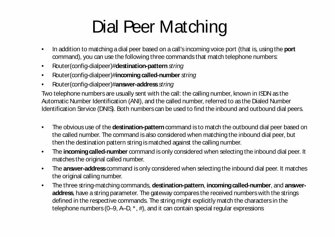
Dial Peer Matching• In addition to matching a dial peer based on a call’s incoming voice port (that is, using the port
command), you can use the following three commands that match telephone numbers:• Router(config-dialpeer)#destination-pattern string• Router(config-dialpeer)#incoming called-number string• Router(config-dialpeer)#answer-address stringTwo telephone numbers are usually sent with the call: the calling number, known in ISDN as the Automatic Number Identification (ANI), and the called number, referred to as the Dialed Number Identification Service (DNIS). Both numbers can be used to find the inbound and outbound dial peers.
• The obvious use of the destination-pattern command is to match the outbound dial peer based on the called number. The command is also considered when matching the inbound dial peer, but then the destination pattern string is matched against the calling number.
• The incoming called-number command is only considered when selecting the inbound dial peer. It matches the original called number.
• The answer-address command is only considered when selecting the inbound dial peer. It matches the original calling number.
• The three string-matching commands, destination-pattern, incoming called-number, and answer-address, have a string parameter. The gateway compares the received numbers with the strings defined in the respective commands. The string might explicitly match the characters in the telephone numbers (0–9, A–D, *, #), and it can contain special regular expressions

String-Matching Characters

Number Matching Examples

Number Matching Examples

Ejercicio
• Numero: 4085551234, que significa la regla aplicada?, como queda el número marcado luego de aplicar el matching?

Matching Inbound Dial Peers• The inbound dial peer determines the call properties for the incoming side of the
call. To match inbound call legs to dial peers, the router uses three elements in the call setup message, as illustrated in Figure, and five configurable dial-peer attributes:
The three call setup elements are, in the example of ISDN, as follows:■ Called number (DNIS): Specifies the destination, which is derived from the ISDNsetup message or channel associated signaling (CAS) DNIS■ Calling number (ANI): Denotes the origin, which is derived from the ISDN setupmessage or CAS ANI■ Voice port: Carries the incoming call

Matching inbound Dial Peers• The gateway selects an inbound dial peer by matching the
information elements in the setup message with the dial-peer attributes. The gateway matches these items in the following order:
• 1. Called number with incoming called-number• 2. Calling number with answer-address• 3. Calling number with destination-pattern• 4. Voice port (associated with the incoming call setup request) with
the configured dial-peer port parameter (applicable for inbound POTS call legs). If no match is found in Step 3, the gateway attempts to match the configured dial-peer port parameter to the voice port associated with the incoming callIf multiple dial peers have the same port configured, the dial peer first added in the configuration is matched
• 5. If there is no match, the default dial peer is used

Matching inbound Dial Peers

Matching Outbound Dial Peer• When a call setup request arrives on a voice gateway, the gateway uses the
incoming dial string to match the destination pattern in the outbound dial peer. Both dial peers—POTS and VoIP—are considered together for outbound dial-peer matching. Once the outbound dial peer is found, the call setup progresses to the next device along the path. On outbound POTS dial peers, the port command is used to forward the call. On outbound VoIP dial peers, the session target command is used to forward the call

Default Dial Peer• Figure depicts a situation in which the call routing works only in one direction. This
scenario brings up the question about the inbound dial peers selected on both gateways. If no inbound peer can be matched by the defined criteria, the gateway resorts to the default dial peer. The default dial peer is referred to as dial peer 0. Default dial peers are used for inbound matches only. They never match outbound calls. The characteristics of dial peer 0 cannot be changed.
Dial peer 0 for inbound VoIP peers has the following characteristics:■ G.729 and G.711 codecs are supported.■ IP precedence is set to 0.■ VAD is enabled.■ RSVP is not supported.■ Fax-rate service is supported.Dial peer 0 for inbound POTS peers has the following characteristics:■ No applications are supported.■ No direct inward dialing is supported

Direct Inward Dialing• In the early days of traditional telephony, enterprises used two-stage
dialing to allow outside callers to reach internal telephones. An enterprise PBX was connected to the PSTN over an analog or digital trunk. When that trunk received an inbound call, the central office (CO) switch seized the voice port. The PBX presented a dial tone and started collecting digits. The caller heard a secondary dial tone from the enterprise PBX and dialed the number required to reach the internal telephone. With the invention of direct inward dialing (DID) in the 1970s, one-stage dialing was made possible. With one-stage dialing, the callers enter the entire called-party number, including the number required to reach the internal telephone. They do not hear a secondary dial tone. The PSTN CO switch sends the entire DNIS to the PBX, which forwards the call to the internal telephone.
• Voice gateways can use DID if it is enabled on inbound POTS dial peers. It is supported on all digital voice ports and the analog FXS-DID ports. It is not supported on analog Foreign Exchange Station (FXS), Foreign Exchange Office (FXO), or ear and mouth (E&M) voice ports

DID – Two Stage Dialing:• Step 1. The user takes the phone off-
hook, receives the dial tone, and dials 555.
• Step 2. The PSTN receives the digits and delivers to the destination gateway. The trunk line to the destination gateway is seized by the adjacent CO switch. The destination gateway presents the secondary dial tone and starts collecting digits until it can identify an outbound dial peer. Whether the digits are dialed with irregular intervals by humans or in a regular fashion by telephony equipment that sends the precollecteddigits, dial-peer matching is done digit by digit. This means that the gateway attempts to match a dial peer after each digit is received.
• Step 3. The user hears the secondary dial tone and dials 2001.
• Step 4. The gateway uses the number 2001 to match the outbound dial peer

DID – Two Stage Dialing – Digit by DigitCollection
• A potential issue related to two-stage dialing is presented in Figure. The destination gateway uses an incorrectly designed dial plan. Because the destination gateway collects the dialed digits in-band, on a digit-by-digit basis, it matches dial peer 2 before the complete number has been received. The call cannot be delivered to its intended recipient

DID - Wildcard• To solve the problem of
the incorrectly designed dial plan and two-stage dialing, use a wildcard in the destination pattern of dial peer 2, as illustrated in Figure . This causes the destination gateway to wait for four digits before making the call-routing decision. With this solution, the call can be delivered to its intended recipient

DID – Gateway by Gateway 1. The user takes the phone off-hook and receives the dial tone from local gateway R1.2. The user dials 55 by entering the digits in irregular intervals.3. R1 collects the two digits (55), matches the outbound dial peer, and seizes the trunk line 1/0/1 toward R2.4. R2 presents the second dial tone.5. The user hears the secondary dial tone and dials 4.6. R2 matches the outbound dial peer. R2 seizes the trunk line 1/0/1 to R3.7. R3 presents the third dial tone.8. The user hears the third dial tone and dials 2001 by entering the digits in irregular intervals.9. R3 keeps collecting digits until the number 2001 has been received. That number matches the outbound dial peer.10. R3 signals an incoming call to the voice port 1/0/1. The recipient phone rings.

DID Variale Lenght Numbers• There are situations in which
expected dial strings do not have a set number of digits. In such cases, it is usually best to use variable-length dial peers by configuring the T terminator on the dial-peer destination-pattern command. When the timer character (T) is included at the end of the destination pattern, as illustrated in Figure 1, the router collects dialed digits until the interdigit timer expires (10 seconds, by default) or until the termination character (the default is #) is dialed
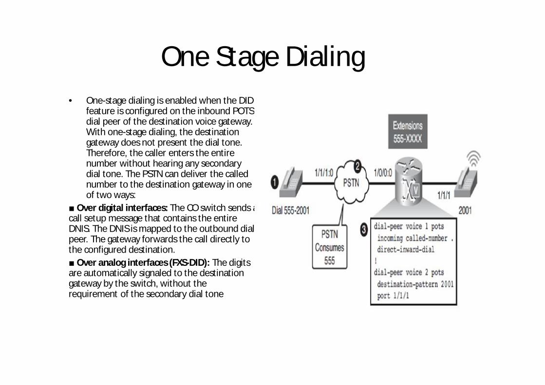
One Stage Dialing• One-stage dialing is enabled when the DID
feature is configured on the inbound POTS dial peer of the destination voice gateway. With one-stage dialing, the destination gateway does not present the dial tone. Therefore, the caller enters the entire number without hearing any secondary dial tone. The PSTN can deliver the called number to the destination gateway in one of two ways:
■ Over digital interfaces: The CO switch sends a call setup message that contains the entire DNIS. The DNIS is mapped to the outbound dial peer. The gateway forwards the call directly to the configured destination.■ Over analog interfaces (FXS-DID): The digits are automatically signaled to the destination gateway by the switch, without the requirement of the secondary dial tone

One Stage Dialing
• 1. The user takes the phone off-hook, receives the dial tone, and dials 555-2001.
• 2. The PSTN delivers the call to the destination gateway. The destination gateway receives the last four digits of the called number in one call setup message or over an analog FXS DID trunk.
• 3. The destination gateway matches the outbound dial peer and signals an incoming call to port 1/1/1. The recipient phone rings
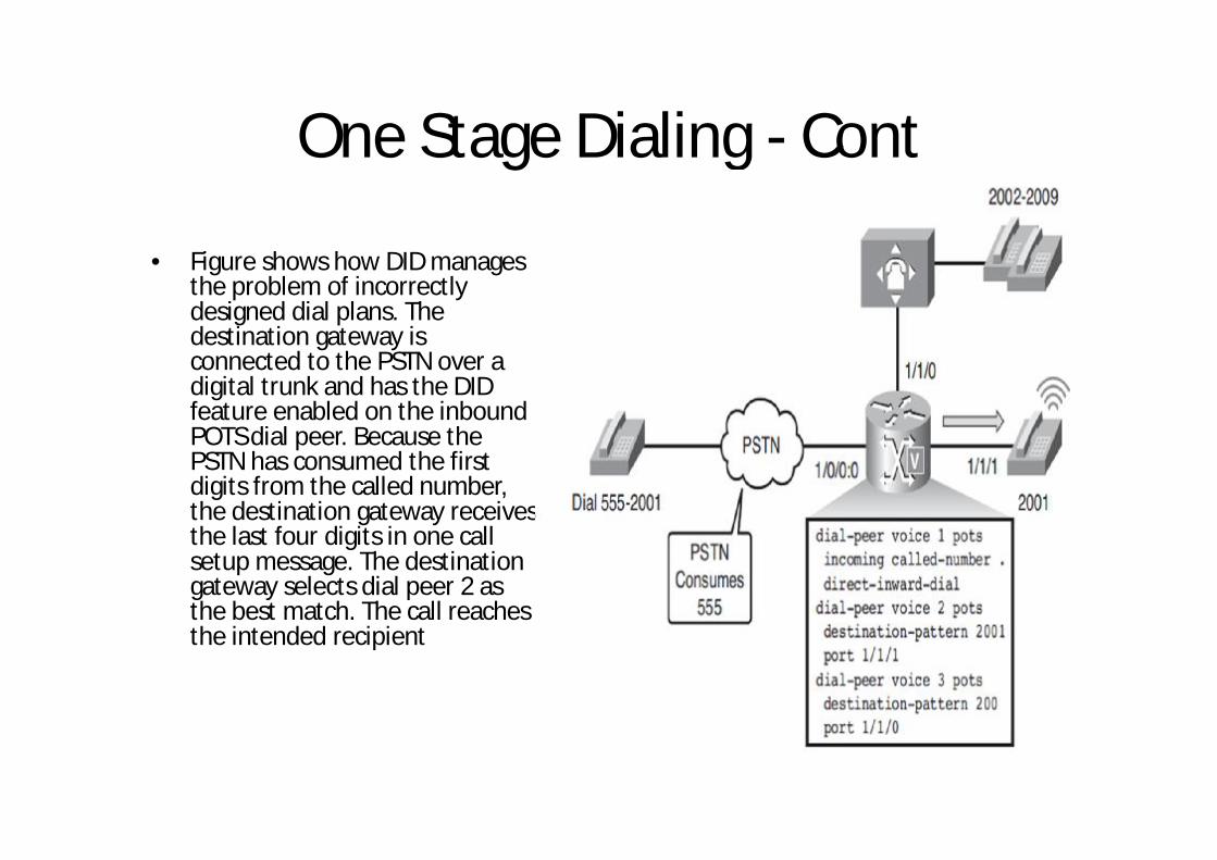
One Stage Dialing - Cont
• Figure shows how DID manages the problem of incorrectly designed dial plans. The destination gateway is connected to the PSTN over a digital trunk and has the DID feature enabled on the inbound POTS dial peer. Because the PSTN has consumed the first digits from the called number, the destination gateway receives the last four digits in one call setup message. The destination gateway selects dial peer 2 as the best match. The call reachesthe intended recipient

One Stage Dialing – Gateway byGateway
1. The user takes the phone off-hook and receives the dial tone from the localgateway R1.2. The user dials 554-2001 by entering the digits in irregular intervals.3. R1 collects the number, matches the outbound dial peer, and finds that the outgoing call leg goes over the digital trunk 1/0/1:0. Because the outgoing voice port is a digital circuit, R1 sends the entire called number in one call setup message. R1 does not forward the first two digits (55) because they are explicitly matched by the destination pattern and are consumed by default (forward-digits all is not configured).4. R2 receives the called number (42001), matches the outbound dial peer 1, and forwards the called number (2001) in a single call setup message over the outgoing digital trunk, to R3. The first digit (4) is consumed through the explicit match by the destination pattern.5. R3 receives the called number (2001) in a single message and matches the outbound dial peer. 6. R3 signals an incoming call to port 1/0/1, and the recipient phone rings

One Stage Dialing DID• As shown in Figure, the DID feature is
configured using the direct-inward-dial command in the incoming dial peer. The inbound dial peer can be matched in various ways.
• The recommended method to match inbound dial peers is to use the incoming callednumber command. The figure displays the two most commonly found DID configurations, while the method using the incoming called-number command is preferred. Note that the timer character (T) is not used in the incoming called-number command, although it is used in destination patterns

Ejemplos
• http://www.cisco.com/c/en/us/support/docs/voice/call-routing-dial-plans/14074-in-dial-peer-match.html
• http://www.cisco.com/c/en/us/td/docs/ios/12_2/voice/configuration/guide/fvvfax_c/vvfpeers.html

Diseño de Redes de Voz sobre IPIng Leonel Hernandez C
Configuring Gateway Voice Ports – DSP - Codex

Objetivos
• Identificar los varios tipos de de voice ports análogos y digitales quese utilizan en distintos escenarios
• Describir los voice ports análogos y digitales y sus características• Verificar las configuraciones de voice ports análogos y digitales• Explicar los codecs de voz y sus principals características• Explicar los varios tipos de DSP y como se usan en gateways• Describir la complejidad de los codecs• Monitorear la operación de los codecs

Analog Voice Ports• Voice ports on routers and access servers emulate physical telephony switch
connections so that voice calls and their associated signaling can be transferred intact between a packet network and a circuit-switched network or device. For a voice call to occur, certain information must be passed between the telephony devices at either end of the call, such as the on-hook status of the devices, the availability of the line, and whether an incoming call is trying to reach a device. This information is referred to as signaling, and to process it properly, the devices at both ends of the call segment, which are directly connected to each other, must use the same type of signaling.
• The devices in a packet network must be configured to convey signaling information in a way that a circuit-switched network can understand. They must also be able to understand signaling information that is received from the circuit-switched network. This is accomplished by installing appropriate voice hardware in a router or access server and by configuring the voice ports that connect to telephony devices or the circuit-switched network. Figure shows typical examples of how voice ports are used

Analog Voice Ports

Analog Voice Ports Interfaces• Analog voice port interfaces connect routers in packet-based networks to analog two wire or four-wire
circuits in telephony networks. Two-wire circuits connect to analog telephone or fax devices, and four-wire circuits connect to PBXs. Connections to the PSTN CO are typically made with digital interfaces. Three types of analog voice interfaces are supported by Cisco gateways, as illustrated in Figure
• The following is a detailed explanation of each of the three types of analog voice interfaces:■ FXS: An FXS interface connects the router or access server to end-user equipment such as telephones, fax
machines, or modems. The FXS interface supplies ring, voltage, and dial tone to the station and includes an RJ-11 connector for basic telephone equipment, key sets, and PBXs.■ FXO: An FXO interface is used for trunk, or tie-line, connections to a PSTN CO or to a PBX that does not
support E&M signaling (when the local telecommunications authority permits). A standard RJ-11 modular telephone cable connects the FXO voice interface card to the PSTN or PBX through a telephone wall outlet.■ E&M: Trunk circuits connect telephone switches to one another. They do not connect end-user equipment
to the network. The most common form of analog trunk circuit is the E&M interface, which uses special signaling paths that are separate from the trunk audio path to convey information about the calls. The signaling paths are known as the E-lead and the M-lead. E&M connections from routers to telephone switches or to PBXs are preferable to FXS and FXO connections, because E&M provides better answer and disconnect supervision

Analog Voice Ports

Analog Signaling• Voice ports on routers and access servers physically connect the router or access server
to telephony devices such as telephones, fax machines, PBXs, and PSTN CO switches. These devices might use any of several types of signaling interfaces to generate information about on-hook status, ringing, and line seizure.
Signaling techniques can be placed into one of three categories:■ Supervisory: Involves the detection of changes to the status of a loop or trunk. When
these changes are detected, the supervisory circuit generates a predetermined response. A circuit (loop) can close to connect a call, for example. Loop start and ground start are supervisory signaling for FXS/FXO■ Addressing: Involves passing dialed digits (pulsed or tone) to a PBX or CO. These dialed
digits provide the switch with a connection path to another phone or customer premisesequipment (CPE). Pulse and Dual Tone Multifrequency (DTMF) are addressing signaling■ Informational: Provides audible tones to the user, which indicate certain conditions such
as an incoming call or a busy phone. Call Progress Tone is the informational signaling

Configuring FXS Ports

Configuring FXO Ports• An FXO trunk is one of the
simplest analog trunks available. Because DNIS information can be sent out only to the PSTN, no DID is possible. ANI is supported for inbound calls. Two signaling types exist, loop-start and ground-start, with ground-start being the preferred method.
• For example, consider the topology shown in Figure. Imagine you have been assigned to configure a voice gateway to route calls to and from the PSTN through an FXO port on the router

Analog and digital ports
• http://elastixtech.com/fundamentos-de-telefonia/interconexion-a-la-pstn/

Trunks• Trunks interconnect gateways or PBX systems to other gateways, PBX
systems, or the PSTN. A trunk is a single physical or logical interface that contains several physical interfaces and connects to a single destination. This could be a single FXO port that provides a single line connection between a Cisco gateway and an FXS port of small PBX system, a POTS device, or several T1 interfaces with 24 lines each in a Cisco gateway providing PSTN lines to several hundred subscribers.
• Trunk ports can be analog or digital and use a variety of signaling protocols. Signaling can be done using either the voice channel (in-band) or an extra dedicated channel (out-of band).
• The available features depend on the signaling protocol in use between the devices. Figure illustrates a variety of possible trunk connections

Trunks

Analog TrunksBecause many organizations continue to use analog devices, a requirement to integrate analog circuits with VoIP or IP telephony networks still exists. To implement a Cisco voice gateway into an analog trunk environment, the FXS, FXO, DID, and E&M interfaces are commonly used, as illustrated in Figure

Analog Trunks Features

Analog Trunks Features (Cont)

Commands to verify Voice Ports

Digital Voice Ports• Digital voice ports are found at the intersection of a packet voice network and a digital,
circuit-switched telephone network. The digital voice port interfaces that connect the router or access server to T1 or E1 lines pass voice data and signaling between the packet network and the circuit-switched network.
• Three types of digital voice circuits are supported on Cisco voice gateways:■ T1: Uses time-division multiplexing (TDM) to transmit digital data over 24 voice channels
using channel associated signaling (CAS).■ E1: Uses TDM to transmit digital data over 30 voice channels using either CAS or
common channel signaling (CCS).■ ISDN: A circuit-switched telephone network system using CCS. Variations of Integrated
Services Digital Network (ISDN) circuits include the following:■ BRI: 2 B (Bearer) channels and 1 D (Delta) channel■ T1 PRI: 23 B channels and 1 D channel■ E1 PRI: 30 B channels and 1 D channel

Digital Trunks• Digital trunks connect to the PSTN, to a PBX, or to the WAN and are widely available worldwide. In some areas, CAS trunks
are the only connections available. Basic Rate Interface (BRI) and Primary Rate Interface (PRI) trunks are very common when connecting a voice gateway to the PSTN.
• Digital voice ports interconnect gateways or PBX systems to other gateways, PBX systems, or the PSTN. A trunk is a single physical or logical interface that contains several logical interfaces and connects to a single destination.
• There are two aspects to consider when signaling on digital lines. One aspect is the actual information about line and device states that is transmitted, and the second aspect is the method used to transmit the information on the digital lines.
• The actual information about line and device states is communicated over digital lines using signaling methods that emulate the methods used in analog circuit-switched networks: Foreign Exchange Station (FXS), Foreign Exchange Office (FXO), and RecEive and TransMit (E&M).
• For signaling to pass between a packet network and a circuit-switched network, both networks must use the same type of signaling. The voice ports on Cisco routers and access servers can be configured to match the signaling of most COs and PBXs. Table lists some of the common digital circuit options. The T1, E1, or ISDN lines that connect a telephony network to the digital voice ports on a router or access server contain channels for voice calls. A T1 or ISDN PRI line contains 24 full-duplex channels or time slots, and an E1 line contains 30. The signal on each channel is transmitted at 64 kbps, a standard known as digital signal level 0 (DS0). The channels are known as DS0 channels. The ds0-group command creates a logical voice port (a DS0 group) from some or all of the DS0 channels, which allows you to address those channels easily, as a group, using voice port configuration commands

Digital Trunks
Digital Signaling• The method used to transmit the information describes the way that the emulated analog signaling is transmitted over
digital lines.
• Digital lines use two types of signaling:
■ CAS: Takes place within the voice channel itself
■ CCS: Sends signaling information over a dedicated channel

Trunks
• http://elastixtech.com/troncales-y-rutas-en-elastix/

ISDNAnother protocol used for digital trunks is ISDN. ISDN is a circuit-switched telephone network system designed to allow digital transmission of voice and data over ordinary telephone copper wires, resulting in better quality and higher speeds than are available with the PSTN system. ISDN comprises digital telephony and data-transport services offered by regional telephone carriers. ISDN involves the digitization of the telephone network, which permits voice, data, text, graphics, music, video, and other source material to be transmitted over existing telephone wires. The emergence of ISDN represents an effort to standardize subscriber services, user/network interfaces, and network and internetwork capabilities.
• ISDN Services
In contrast to the CAS and R2 signaling, which provide only DNIS, ISDN offers additional supplementary services such as call waiting and Do Not Disturb (DND). ISDN applications include high-speed image applications (such as Group IV facsimile), additional telephone lines in homes to serve the telecommuting industry, high-speed file transfer, and video conferencing. Voice service is also an application for ISDN.
• ISDN Media Types
Cisco routing devices support ISDN BRI and ISDN PRI. Both media types use B channels and D channels. The B channels carry user data. The D channel, in its role as signal carrier for the B channels, directs the CO switch to send incoming calls to particular time slots on the Cisco access server or router. It also identifies the call as a circuit-switched digital call or an analog modem call. Circuit-switched digital calls are relayed directly to the ISDN processor in the router. Analog modem calls are decoded and then sent to the onboard modems. Figure illustrates three sample ISDN installation options

ISDN Installation Options (CCS Signaling)

ISDN BRI and PRI Interfaces

ISDN SignalingISDN uses Q.921 as its Layer 2 signaling protocol, and Q.931 as its Layer 3 signaling protocol.
• Q.921 Layer 2 of the ISDN signaling protocol is also known as Link Access Procedure, D channel (LAPD). LAPD is similar to High-Level Data Link Control (HDLC) and Link Access Procedure, Balanced (LAPB). As the expansion of the LAPD acronym indicates, this layer is used across the D channel to ensure that control and signaling information flows and is received properly. The LAPD frame format is very similar to that of HDLC. Like HDLC, LAPD uses supervisory information and unnumbered frames. The LAPD protocol is formally specified in ITU-T Q.920 and ITU-T Q.921. The Terminal Endpoint Identifier (TEI) field identifies either a single terminal or multiple terminals. A TEI of all 1s indicates a broadcast.
• Q.931 Two Layer 3 specifications are used for ISDN signaling: ITU-T I.450 (also known as ITU-T Q.930) and ITU-T I.451 (also known as ITU-T Q.931). Together, these protocols support user-to-user, circuit-switched (the B channels), and packet-switched (the D channel) connections. A variety of call-establishment, call-termination, information, and miscellaneous messages are specified, including SETUP, CONNECT, RELEASE, USER INFORMATION, CANCEL, STATUS, and DISCONNECT. These messages are functionally similar to those provided by the X.25 protocol.

Configuring digital voice portsBefore configuring a T1 or E1 trunk, you must decide on a variety of parameters for the T1 or E1 digital controller. The following discussions explain the implications of these parameter selections.
• Framing Formats The framing format parameter describes the way bits are robbed from specific frames to be used for signaling purposes. The controller must be configured to use the same framing format as the line from the PBX or CO that connects to the voice port you are configuring. Digital T1 lines use SF or ESF framing formats.
• Line Coding Digital T1/E1 interfaces require that line coding be configured to match that of the PBX or CO that is being connected to the voice port. Line coding defines the type of framing that is used on the line
• Clock Sources Digital T1/E1 interfaces use timers called clocks to ensure voice packets are delivered and assembled properly. All interfaces handling the same packets must be configured to use the same source of timing so packets are not lost or delivered late. The timing source that is configured can be external (from the line) or internal to a router’s digital interface.
• DS0 Groups For digital voice ports, a single command, ds0-group, performs the following functions:
■ Defines the T1/E1 channels for compressed voice calls
■ Automatically creates a logical voice port
■ Defines the emulated analog signaling method the router uses to connect to the PBX or PSTN

Configuring digital voice ports - Timing

Configuring ISDN BRI Trunk

Configuring ISDN PRI Trunk

Verifying Analog – Digital Ports
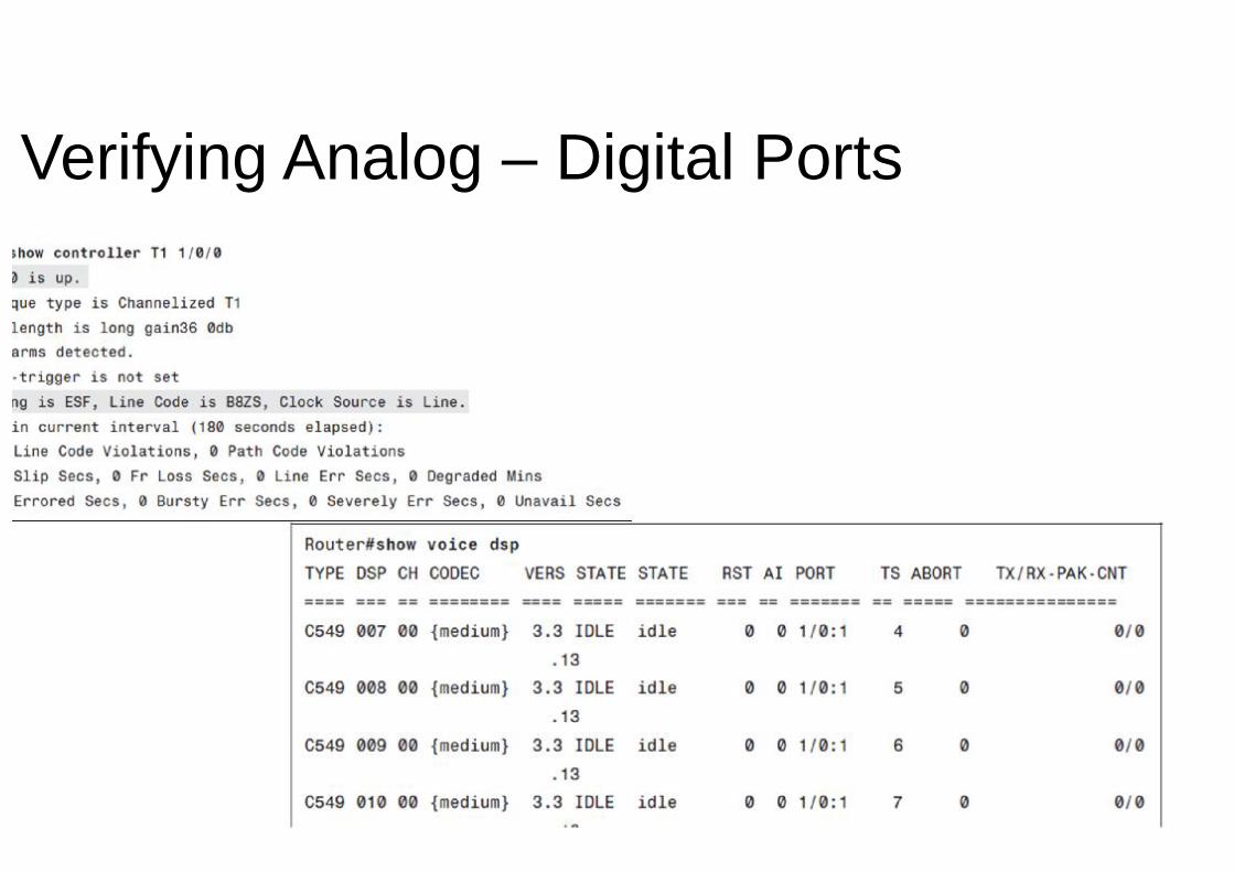
Verifying Analog – Digital Ports

Verifying Analog – Digital Ports

Verifying Analog – Digital Ports

ISDN Configuration
• http://www.cisco.com/cisco/web/support/LA/107/1073/1073834_dia_cfg_isdn_spcl_sgnl_ps6922_TSD_Products_Configuration_Guide_Chapter.pdf

Voice Packets Processing with Codecsand DSPs• A codec is a device or program capable of performing encoding and decoding on a digital
data stream or signal. Various types of codecs are used to encode and decode or compress and decompress data that would otherwise use large amounts of bandwidth on WAN links. Codecs are especially important on lower-speed serial links, where every bit of bandwidth is needed and utilized to ensure network reliability. One of the most important factors for a network administrator to consider while building voice networks is proper capacity planning. Network administrators must understand how much bandwidth is used for each VoIP call. To understand bandwidth, the administrator must know which codec is being utilized across the WAN link. With a thorough understanding of VoIP bandwidth and codecs, the network administrator can apply capacity planningtools.
• Coding techniques are standardized by the ITU. The ITU-T G-series codecs are among the most popular standards for VoIP applications. Following is a list of codecs supported by Cisco IOS gateways:■ G.711: The international standard for encoding telephone audio on a 64-kbps channel. It
is a PCM scheme operating at an 8-kHz sample rate, with 8 bits per sample. With G.711, the encoded voice is already in the correct format for digital voice delivery in

Codecs
the PSTN or through PBXs. It is widely used in the telecommunications field because it improves the signal-to-noise ratio without increasing the amount of data.There are two subsets of the G.711 codec:■ mu-law: Used in North American and Japanese phone networks■ a-law: Used in Europe and elsewhere around the world
Both mu-law and a-law subsets use digitized speech carried in 8-bit samples. They use an 8-kHz sampling rate with 64 kbps of bandwidth demand.

Codecs■ G.726: An ITU-T Adaptive Differential Pulse-Code Modulation (ADPCM) coding at 40, 32, 24, and 16 kbps. ADPCM-encoded voice can be interchanged between packet voice, PSTN, and PBX networks if the PBX networks are configured to support ADPCM. The four bit rates associated with G.726 are often referred to by the bit size of a sample, which are 2 bits, 3 bits, 4 bits, and 5 bits, respectively.■ G.728: Describes a 16-kbps Low-Delay Code Excited Linear Prediction (LDCELP) variation of CELP voice compression. CELP voice coding must be translated into a public telephony format for delivery to or through the PSTN.■ G.729: Uses Conjugate Structure Algebraic Code Excited Linear Prediction (CSACELP) compression to code voice into 8-kbps streams. G.729a (that is, G.729 Annex A) requires less computation, but the lower complexity is not without a tradeoff because speech quality is marginally worsened. Also, G.729b (that is, G.729 Annex B) adds support for VAD and CNG, to cause G.729 to be more efficient in its bandwidth usage. The features of G.729a and G.729b can be combined into G.729ab. Standard G.729 operates at 8 kbps, but there are extensions that provide 6.4 kbps (Annex D) and 11.8 kbps (Annex E) rates for marginally worse and better speech quality, respectively.

Codecs• G.723: Describes a dual-rate speech coder for multimedia communications. This compression
technique can be used for compressing speech or audio signal components at a very low bit rate as part of the H.324 family of standards. This codec has two bit rates associated with it:■ r63: 6.3 kbps; using 24-byte frames and the MPC-MLQ (Multipulse LPC with Maximum
Likelihood Quantization) algorithm■ r53: 5.3 kbps; using 20-byte frames and the ACELP algorithm The higher bit rate is based on ML-
MLQ technology and provides a somewhat higher quality of sound. The lower bit rate is based on CELP and provides system designers with additional flexibility.• ■ GSM Full Rate Codec (GSMFR): Introduced in 1987, the GSMFR speech coder has a frame size
of 20 ms and operates at a bit rate of 13 kbps. GSMFR is an RPE-LTP (Regular Pulse Excited–Linea Predictive) coder. To write VoiceXML scripts that can function as the user interface for a simple voice-mail system, the network must support GSMFR codecs. The network messaging must be capable of recording a voice message and depositing the message to an external server for later retrieval. This codec supports the Cisco infrastructure and application partner componentsrequired for service providers to deploy unified messaging applications.

Codecs
• ■ Internet Low Bit Rate Codec (iLBC): Designed for narrowband speech, it results in a payload bit rate of 13.33 kbps for 30-ms frames and 15.20 kbps for 20-ms frames. The algorithm is a version of Block-Independent Linear Predictive Coding, with the choice of data frame lengths of 20 and 30 ms. The encoded blocks have to be encapsulated in a suitable protocol for transport, such as RTP. This codec enables graceful speech quality degradation in the case of lost frames, which occurs in connection with lost or delayed IP packets.

Impact of voice samples and packet sizeon BW• Voice sample size is a variable that can affect total bandwidth used. A voice sample is defined as
the digital output from a codec’s DSP encapsulated into a protocol data unit (PDU). Cisco uses DSPs that output samples based on digitization of 10 milliseconds’ worth of audio. Cisco voice equipment encapsulates 20 ms of audio in each PDU by default, regardless of the codec used. You can apply an optional configuration command to vary the number of samples encapsulated. When you encapsulate more samples per PDU, the total bandwidth is reduced. However, encapsulating more samples per PDU comes at the risk of larger PDUs, which can cause variable delay and severe gaps if PDUs are dropped. Table demonstrates how the number of packets required to transmit one second of audio varies with voice sample sizes.
• Using a simple formula, it is possible for you to determine the number of bytes encapsulated in a PDU based on the codec bandwidth and the sample size (20 ms is the default):
Bytes_per_Sample = (Sample_Size * codec_Bandwidth) / 8If you apply G.711 numbers, the formula reveals the following:
Bytes_per_Sample = (.020 * 64000) / 8Bytes_per_Sample = 160

Impact of Voice Samples

Evaluating Quality of Codecs
• MOS (Mean Opinion Score)• PESQ (Perceptual Evaluation of Speech Quality)• PEAQ (Perceptual Evaluation of Audio Quality)
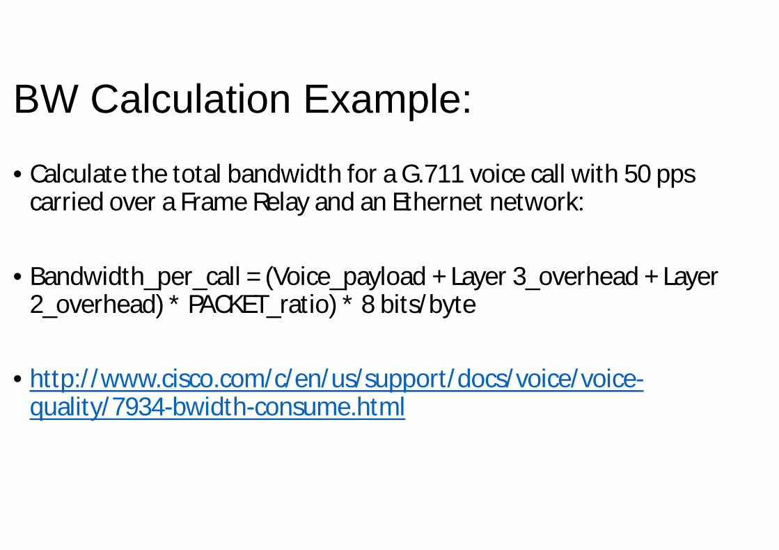
BW Calculation Example:
• Calculate the total bandwidth for a G.711 voice call with 50 ppscarried over a Frame Relay and an Ethernet network:
• Bandwidth_per_call = (Voice_payload + Layer 3_overhead + Layer 2_overhead) * PACKET_ratio) * 8 bits/byte
• http://www.cisco.com/c/en/us/support/docs/voice/voice-quality/7934-bwidth-consume.html

Digital Signal Processors• A DSP is a specialized microprocessor designed specifically for digital signal
processing. DSPs enable Cisco platforms to efficiently process digital voice traffic. DSPs on a router provide stream-to-packet signal processing functionality that includes voice compression, echo cancellation, and tone- and voice-activity detection.
• A media resource is a software-based or hardware-based entity that performs media processing functions on the data streams to which it is connected. A few examples are media-processing functions that include mixing multiple streams to create one output stream (conferencing), passing the stream from one connection to another (media termination point), converting the data stream from one compression type to another (transcoding), echo cancellation, signaling, termination of a voice stream from a TDM circuit (coding/decoding), packetization of a stream, and streaming audio (annunciation).
• The terms DSP and media resource are often used interchangeably in some documentation

DSP Functions• ■ Transcoding: Transcoding is the direct digital-to-digital conversion from one codec to another. Transcoding
compresses and decompresses voice streams to match endpoint-device capabilities. Transcoding is required when an incoming voice stream is digitized and compressed (by means of a codec) to save bandwidth, but the local device does not support that type of compression. Ideally, all IP telephony devices would support the same codecs, but this is not the case. Rather, different devices support different codecs.
• ■ Voice termination: Voice termination applies to a call that has two call legs, one leg on a TDM interface and the second leg on a VoIP connection. The TDM leg must be terminated by hardware that performs coding/decoding and packetization of the stream. DSPs perform this termination function. The DSP also provides echo cancellation, voice activity detection, and jitter management at the same time it performs voice termination.
• ■ Media termination point (MTP): An MTP is an entity that accepts two full-duplex voice streams using the same codec. It bridges the media streams and allows them to be set up and torn down independently. The streaming data received from the input stream on one connection is passed to the output stream on the other connection, and vice versa. In addition, the MTP can be used to transcode a-law to mu-law and vice versa, or it can be used to bridge two connections that utilize different packetization periods. MTPs are also used to provide further processing of a call, such as RFC 2833 support
• ■ Audio conferencing: In a traditional circuit-switched voice network, all voice traffic goes through a central device (such as a PBX system), which provides audio conferencing services as well. Because IP phones transmit voice traffic directly between phones, a network-based conference bridge is required to facilitate multiparty conferences

DSP

DSP• DSP ChipThe DSP chip plays a crucial role in the Cisco Unified Communications system. The DSP chip comes in several form factors, from soldered on to the main board of the Cisco Unified IP phone or gateway, to the modular packet voice DSP module (PVDM). The PVDM can have multiple DSPs on the module. The type of DSP chip, the number of DSP resources, and the type of codec that is used all factor into the calculation of how many simultaneous calls can be processed.• DSP ModulesCurrently, there are two major types of high-density PVDMs: PVDM generation 2 (PVDM2) and PVDM generation 3 (PVDM3). The Cisco 2800 and 3800 Series platforms support only the PVDM2 modules. The Cisco 2900 and 3900 Series platforms support both the PVDM2 and PVDM3 modules. The PVDM3 modules provide higher density (up to four times higher) than the PVDM2s. They also provide improved performance in terms of the number of conference and transcoding sessions supported

DSP Module Comparison

Codex Complexity
• Codec complexity refers to the amount of processing that is required to perform voice compression. Codec complexity affects call density, which is the number of calls that are reconciled on the DSPs. With higher codec complexity, fewer calls can be processed, as illustrated in Table. A higher codec complexity might be required to support a particular codec or combination of codecs. A lower codec complexity supports the greatest number of voice channels, if the lower complexity is compatible with the particular codecs in use

Codex Complexity

Configuring DSP:• The codec complexity can be configured to tell the gateway how many DSP resources to allocate
to a voice channel. These settings are available:■ High complexity: This option supports any high-complexity codec or a combination of high- and lower-complexity codecs.■ Medium complexity: This option supports any medium-complexity codec or a combination of medium- and low-complexity codecs. It offers the greatest number of voice channels, if the lower complexity is compatible with the particular codecs in use. All medium-complexity codecs can also be run in high-complexity mode, but fewer (usually about half) of the channels are available per DSP.■ Flex: In this option, more voice channels can be connected (or configured in the case of DS0 groups and PRI groups) to the module than the DSPs can accommodate. If all voice channels should go active simultaneously, the DSPs become oversubscribed, and calls that are unable to allocate a DSP resource fail to connect. This is the default setting.■ Secure: This option supports the Secure Real-Time Transport Protocol (SRTP) package capability for media encryption and authentication. This setting supports thelowest number of selected low-and medium-complexity codecs (G.711 a-law and mu-law, G.729, and G.729A) per DSP.

Configuring DSP – Voice Card

DSP Farms
• A DSP farm is the collection of DSP resources available for conferencing, transcoding, and MTP services. DSP farms are configured on the voice gateway and managed by Cisco Unified Communications Manager through SCCP

DSP Farms - Profile

Verifying Codex Complexity

• GRACIAS!!!!!


![[VoIP] Cisco CallManager Basics (VoIP)](https://static.documents.pub/doc/80x56/55cf99c3550346d0339f0d92/voip-cisco-callmanager-basics-voip.jpg)


