79
MANAGING URBAN STORMWATER Soils and Construction Volume 2E Mines and quarries
| Date post: | 21-Jan-2017 |
| Category: |
Documents |
| Upload: | vuonghuong |
| View: | 219 times |
| Download: | 1 times |
MANAGING URBAN STORMWATER
Soils and Const r uct ion
Volume 2E Mines and quarries
MANAGING URBAN STORMWATERSoils and Const r uct ion
Volume 2E Mines and quarries
Disclaimer: The Department of Environment and Climate Change NSW has prepared this publication in good faith exercising all due care and attention, but no representation or warranty, express or implied, is made as to the relevance, accuracy, completeness or fi tness for purpose of this publication in respect of any particular user’s circumstances. Users of this publication should satisfy themselves concerning its application to, and where necessary seek expert advice in respect of, their situation.
© Copyright State of NSW and Department of Environment and Climate Change 2008.
This material may be reproduced for non-commercial purposes in whole or in part, provided the meaning is unchanged and the source is acknowledged.
Published by the Department of Environment and Climate Change NSW in association with the Sydney Metropolitan Catchment Management Authority.
Department of Environment and Climate Change NSW59–61 Goulburn StreetPO Box A290Sydney South 1232Phone: (02) 9995 5000 (switchboard)Phone: 131 555 (environment information and publications requests)Phone: 1300 361 967 (national parks information and publications requests)Fax: (02) 9995 5999TTY: (02) 9211 4723Email: [email protected]: www.environment.nsw.gov.au
Sydney Metropolitan Catchment Management AuthorityGround Floor, 10 Valentine Avenue PO Box 3720Parramatta NSW 2124 Tel: 9895 7898 Fax: 9895 7330 Email: [email protected] Website: www.sydney.cma.nsw.gov.au
Cover photo: Quarry, Eastern CreekDECC
ISBN: 978 1 74122 816 8DECC 2008/208June 2008
Printed on environmentally sustainable paper
Contents
iii
Acknowledgments iv
1 Introduction 1
2 Statutory requirements 5
3 Erosion and sediment control strategy 9
4 Mine and quarry design 17
5 Mine and quarry rehabilitation 23
6 Erosion and sediment control techniques 29
Bibliography 38
Appendices 39
Appendix A: Types of mining-related activity 40
Appendix B: Threshold criteria for scheduled activities 43
Appendix C: Erosion and sediment control planning 44
Appendix D: Sample ESCP for small quarry 46
Appendix E: Sample ESCP for large mine 50
Appendix F: Selection of control measures 69

AcknowledgmentsThis publication was funded by the NSW Government through the Stormwater Trust.
Photography credits:
Contents opener Newstan Coal mine, FassifernDECC
Section 1 opener Quarry, Eastern CreekDECC
Section 2 opener Newstan Coal mine, FassifernDECC
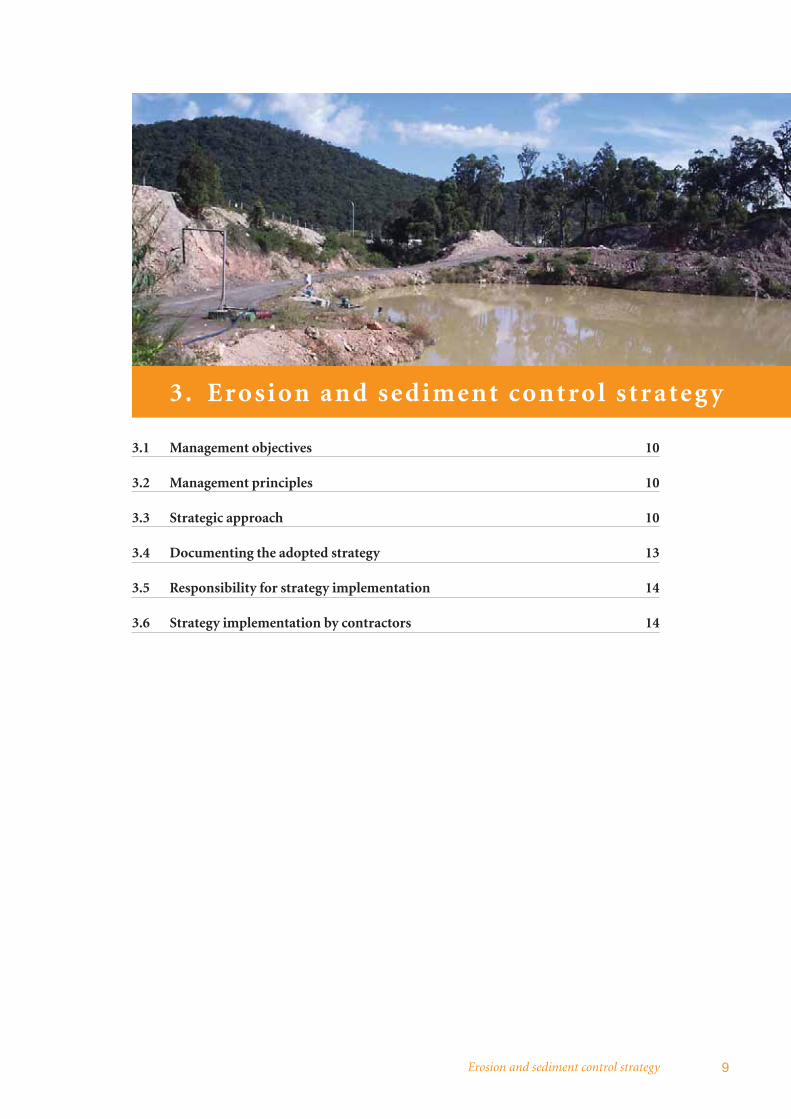
Section 3 opener Quarry, Hunter ValleyDECC
Section 4 opener Stockyard Creek quarry, TorontoDECC
Section 5 opener Quarry, Eastern CreekDECC
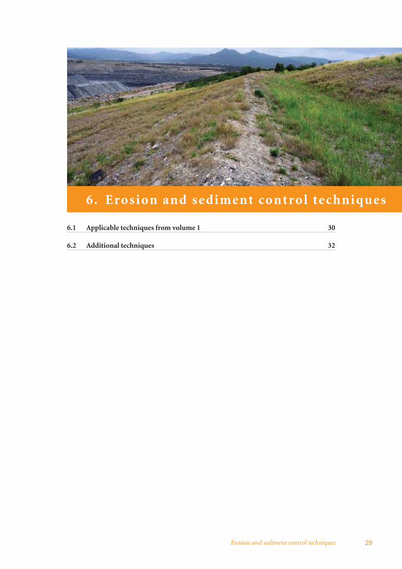
Section 6 opener Coal mine, Hunter ValleyChad Stockham/GSS Environmental
Appendices opener Stockyard Creek quarry, TorontoDECC
iv
Introduction 1
1. Int ro duct ion
1.1 Mines and quarries 2
1.2 Purpose and scope 2
1.3 Types of mining and mining-related activity 3
1.4 Potential impacts on the water environment 3
1.5 Structure of this publication 4
Managing urban stormwater: soils and construction – mines and quarries2
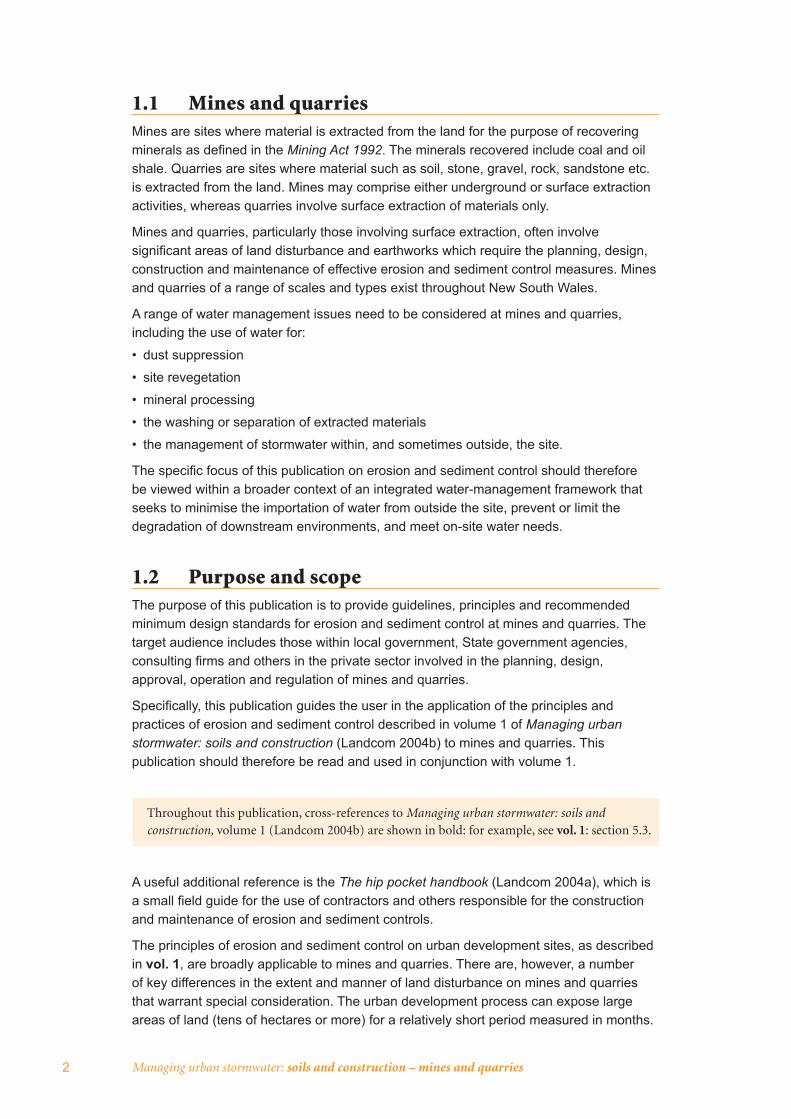
1.1 Mines and quarries Mines are sites where material is extracted from the land for the purpose of recovering minerals as defi ned in the Mining Act 1992. The minerals recovered include coal and oil shale. Quarries are sites where material such as soil, stone, gravel, rock, sandstone etc. is extracted from the land. Mines may comprise either underground or surface extraction activities, whereas quarries involve surface extraction of materials only.
Mines and quarries, particularly those involving surface extraction, often involve signifi cant areas of land disturbance and earthworks which require the planning, design, construction and maintenance of effective erosion and sediment control measures. Mines and quarries of a range of scales and types exist throughout New South Wales.
A range of water management issues need to be considered at mines and quarries, including the use of water for:
• dust suppression
• site revegetation
• mineral processing
• the washing or separation of extracted materials
• the management of stormwater within, and sometimes outside, the site.
The specifi c focus of this publication on erosion and sediment control should therefore be viewed within a broader context of an integrated water-management framework that seeks to minimise the importation of water from outside the site, prevent or limit the degradation of downstream environments, and meet on-site water needs.
1.2 Purpose and scope The purpose of this publication is to provide guidelines, principles and recommended minimum design standards for erosion and sediment control at mines and quarries. The target audience includes those within local government, State government agencies, consulting fi rms and others in the private sector involved in the planning, design, approval, operation and regulation of mines and quarries.
Specifi cally, this publication guides the user in the application of the principles and practices of erosion and sediment control described in volume 1 of Managing urban stormwater: soils and construction (Landcom 2004b) to mines and quarries. This publication should therefore be read and used in conjunction with volume 1.
Throughout this publication, cross-references to Managing urban stormwater: soils and construction, volume 1 (Landcom 2004b) are shown in bold: for example, see vol. 1: section 5.3.
A useful additional reference is the The hip pocket handbook (Landcom 2004a), which is a small fi eld guide for the use of contractors and others responsible for the construction and maintenance of erosion and sediment controls.
The principles of erosion and sediment control on urban development sites, as described in vol. 1, are broadly applicable to mines and quarries. There are, however, a number of key differences in the extent and manner of land disturbance on mines and quarries that warrant special consideration. The urban development process can expose large areas of land (tens of hectares or more) for a relatively short period measured in months.
Introduction 3
On the other hand, the operational lives of mines and quarries are typically measured in decades, and the extent of land disturbance can vary from limited, for underground mining operations, to far-reaching for signifi cant surface (open-cut) mining activities and quarries. The impacts can, however, be reduced through good planning, operation and monitoring of erosion and sediment control measures.
This publication does not address broader water and environmental issues associated with mines and quarries. These activities can have a range of potential environmental impacts beyond erosion and sedimentation, which should be identifi ed and assessed in the project planning and environmental assessment phase.
1.3 Types of mining and mining-related activityMines and quarries are found in a wide variety of climates and landscapes, and include a broad range of layouts and products. Various extraction methods are used, ranging from major open-cut and strip-mine operations, to underground long-wall and hard-rock ore mining, dredging operations, soil and gravel extraction, and hand excavation of gemstones. Given this variety, management techniques to minimise environmental impacts cannot be standardised.
The extent and nature of mining impacts can range from minimal to signifi cant depending on factors associated with each type of mine or quarry. These factors include:
• characteristics of the ore body
• type of technology and methods used in the extraction and on-site processing of minerals
• nature and sensitivity of the local environment
• expectations for post-mining land use.
A brief discussion of common mining types and their associated soil and water management issues is in appendix A.
1.4 Potential impacts on the water environmentThe scale and nature of contemporary mines and quarries mean that they have the potential to signifi cantly impact surface runoff and groundwater quality through contamination with dissolved and suspended material. Water-quality issues in mines and quarries include:
• sediment-laden runoff from overburden emplacements, waste-rock dumps, stockpiles and other disturbed areas
• stormwater contamination from process plants, workshops, vehicle wash-down areas etc.
• acidic mine drainage from the oxidisation of sulfur or sulfuric ores, which can also contain dissolved heavy metals
• elevated salinity levels, as mining can disrupt saline aquifers or allow salt to be leached from freshly shattered overburden.
The most common surface-water contaminant from mining and quarrying is sediment or ‘total suspended solids’ (TSS), produced by soil erosion from lands disturbed by the mining or quarrying activity. This publication focuses on the control of soil erosion and sediment pollution from mines and quarries.

Managing urban stormwater: soils and construction – mines and quarries4
1.5 Structure of this publicationSection 2 provides an overview of the regulatory framework for erosion and sediment control for mines and quarries
Section 3 outlines the approach that can be taken in developing an erosion and sediment control strategy for a mine or quarry
Section 4 summarises considerations in the design of mines and quarries that are relevant to operational erosion and sediment control
Section 5 provides information on mine and quarry rehabilitation relevant to minimising site erosion
Section 6 provides guidance on applicable erosion and sediment control techniques at mines and quarries
The appendices contain guidance on erosion and sediment control plans (ESCPs).
Statutory requirements 5
2. Statutor y requirements
2.1 General 6
2.2 Relevant legislation 6
Managing urban stormwater: soils and construction – mines and quarries6
2.1 OverviewA number of State and local regulatory authorities will need to be consulted to ensure activities associated with mines and quarries are undertaken in accordance with all necessary statutory requirements.
Several pieces of legislation may need to be considered in the planning and design stages of a mine or quarry site, including the Environmental Planning and Assessment Act 1979 (EP&A Act). Mining developments generally need to obtain approval under the Mining Act 1992, while mining and quarry projects are also likely to be subject to the requirements of the Protection of the Environment Operations Act 1997 (POEO Act). The requirements of these three key pieces of legislation are described in the section below.
Other Acts which may infl uence aspects of erosion and sediment control include:
• Water Management Act 2000
• Native Vegetation Act 2003
• Threatened Species Conservation Act 1995
• National Parks and Wildlife Act 1974
• Soil Conservation Act 1938
• Fisheries Management Act 1984
While these Acts are not discussed in any detail in this publication, more detailed description of them is presented in vol. 1: appendix K and at www.environment.nsw.gov.au/legislation.
The information below was current at the time of publication. However, statutory requirements and the roles of government agencies can change over time – proponents should therefore check that this information is current during the planning stage of their project.
2.2 Relevant legislation
2.2.1 Environmental Planning and Assessment Act 1979The EP&A Act specifi es the planning approval and development consent requirements for mines and quarries. The State Environmental Planning Policy (SEPP) Mining,petroleum production and extractive industries 2007 notes the types of mining operations permissible under the EP&A Act with and without development consent. Generally only exploration and rehabilitation activities are permitted without consent, while mining or quarrying developments require consent.
This SEPP requires consent authorities to consider whether or not the consent should be issued subject to conditions to ensure that impacts on signifi cant water resources, including surface water and groundwater, are either avoided or minimised as far as practicable.
Where development consent is required and the development exceeds thresholds set by the EP&A Act, the development is considered a ‘designated development’ and an environmental impact statement (EIS) must be lodged with the application. Where an EIS is not required, a statement of environmental effects (SEE) generally has to be lodged. Most medium-to-large quarries and mines (including all underground coal mines) are designated developments.
Statutory requirements 7
The following documents provide guidance on the contents of an EIS, including the water management issues to be addressed:
• EIS guideline: extractive industries – quarries (Planning NSW 1996b)
• EIS guideline: extractive industries – dredging and other extraction in riparian and coastal areas (Planning NSW 1996a)
• EIS guideline: coal mines and associated infrastructure (DUAP 2000).
2.2.2 Protection of the Environment Operations Act 1997A mine or quarry is a ‘scheduled activity’ under the POEO Act if it exceeds the thresholds set out in schedule 1 of that Act – see appendix B of this publication for the relevant threshold criteria relating to mines and quarries.
An environment protection licence under the POEO Act must be obtained prior to the commencement of any works associated with a scheduled activity. The regulatory body responsible for the consideration and determination of applications for an environment protection licence is the NSW Environment Protection Authority (EPA), part of the Department of Environment and Climate Change NSW (DECC). The impact on the environment of any pollution likely to be caused by the activity will be considered when determining an application for an environment protection licence.
Where an environment protection licence is granted, conditions may include soil and water management requirements to avoid or minimise these potential impacts. Such conditions may include specifi cations for the ‘design storm’ for which all sediment-laden runoff from the site should be retained or adequately treated (typically by a sediment basin) to achieve the required discharge water quality.
Local councils are generally the appropriate regulatory authority for the environmental performance of most activities not scheduled under the POEO Act. Local councils have notice and enforcement powers under the POEO Act for these activities and are also required to consider soil and water issues under the Act. The EPA is the appropriate regulatory authority for unscheduled activities carried out by councils and NSW government agencies – this will be applicable where, for example, a council operates a small quarry.
2.2.3 Mining Act 1992Mining and associated exploration activities must be undertaken in accordance with approvals issued under the Mining Act 1992.
There are fi ve types of approvals issued under the Act all of which can be granted subject to conditions, including conditions for protection of the environment. The conditions often include requirements for addressing soil and water issues. For mining operations, the conditions of approval require mining to be undertaken in accordance with a mining operations plan (MOP) that has been assessed and approved by the Department of Primary Industries (DPI). The MOP documents site activities and progress towards the required environmental and rehabilitation outcomes, including a description of the soil and water management measures to be implemented.
The contents of a MOP are described in DPI (2006) and include water management arrangements for:
• mine operations, including structures for managing polluted water
• mine rehabilitation, including drainage and erosion control to minimise water pollution.

Managing urban stormwater: soils and construction – mines and quarries8
The MOP provides a sound framework for the integration of detailed water management, erosion and sediment control, and progressive site rehabilitation within the mining operation. A water management plan and an erosion and sediment control plan (ESCP) are commonly sub-elements of the MOP documentation.
Erosion and sediment control strategy 9
3. Erosion and sediment cont rol st r ate g y
3.1 Management objectives 10
3.2 Management principles 10
3.3 Strategic approach 10
3.4 Documenting the adopted strategy 13
3.5 Responsibility for strategy implementation 14
3.6 Strategy implementation by contractors 14
Managing urban stormwater: soils and construction – mines and quarries10
3.1 Management objectives The goal for erosion and sediment control from a mine or quarry is to ensure no pollution of surface water or groundwater. Current best-practice erosion and sediment control techniques are, however, unlikely to achieve this goal, due to the limited effectiveness of most of the techniques. An appropriate management objective is therefore to minimise the water-quality impacts from erosion and sedimentation through implementing best-practice management techniques.
Given this limited effectiveness of techniques for retaining eroded sediment, a strong emphasis should be placed on pollution prevention through erosion control, rather than relying on treatment techniques to capture these sediments.
3.2 Management principles The primary principles for erosion and sediment control are fi rstly to minimise erosion and then to capture sediment from disturbed areas. This approach emphasises pollution prevention rather than pollution control.
Vol. 1: section 1.6 identifi es seven general principles of effective soil and water management for land disturbance associated with urban development. This approach focuses on appropriate site planning, and the installation of appropriate erosion control and sediment control measures.
These principles also broadly apply to the planning, design, construction and operation of mines and quarries. They can be paraphrased as follows:
• assess the soil and water implications of a project at the planning stage
• plan for erosion and sediment control during the project’s design and before any earthworks begin, including assessment of site constraints
• minimise the area of soil disturbed and exposed to erosion
• conserve topsoil for later site rehabilitation or regeneration (in a stabilised stockpile)
• control water fl ow from the top of and through the project area by diverting up-slope ‘clean’ water away from disturbed areas and ensuring that concentrated fl ows are below erosive levels and sediment is retained from disturbed areas
• rehabilitate disturbed lands quickly
• maintain erosion and control measures appropriately.
3.3 Strategic approach
3.3.1 OverviewEffective erosion and sediment control for a mine or quarry requires appropriate activities to be carried out over the life of the project including:
• planning and design
• operations
• closure and rehabilitation.
The principles noted in section 3.2 above can be used to guide the development of an erosion and sediment control strategy for a mine or quarry. The specifi c strategy adopted will vary depending on the nature and scope of the development, type and sensitivity of
Erosion and sediment control strategy 11
receiving environments, and other factors such as site rainfall characteristics, soils and topography. It is important that any erosion and sediment control strategy is consistent with, and meets the requirements of, any applicable environment protection licence, development consent or approval conditions.
As with construction sites, the magnitude of erosion problems (and therefore the effort required to control erosion) at mine and quarry sites is proportional to the:
• area of soil exposed to the erosive elements, and
• duration of that exposure.
Mines and quarries are characterised by land disturbance operations continuing for years (if not decades) rather than months. Because of this longer period of operation, the management focus should be on site design and the scheduling of rehabilitation to minimise erosion occurring, rather than the sole reliance on temporary works to control erosion and sedimentation.
This long period of disturbance, and long operation of many erosion and sediment controls, requires a stronger emphasis on some management principles particularly:
• erosion control, as a pollution prevention strategy
• runoff separation by diverting ‘clean’ stormwater runoff around the site or away from operational areas
• management and maintenance of long-term controls.
3.3.2 Planning and design strategiesThe effectiveness of erosion and sediment controls during the operational and rehabilitation stages can be optimised through effective mine and quarry planning and design. Suitable strategies include:
• designing any drainage systems operating for the life of the mine or quarry so that they do not cause erosion. This may involve scour protection of open drains and energy dissipaters located at drain outlets
• diverting runoff around the mine or quarry site where possible, to minimise external runoff fl owing to operational areas
• designing the fi nal mine or quarry geometry to create a landform that allows free drainage of surface runoff while minimising erosion. This includes designing an appropriate drainage system that avoids erosion
• staging open-cut mining or quarrying to minimise the operational area exposed at any one time. This helps to reduce the potential for erosion and the extent and capacity of erosion and sediment control measures required, especially where the operational area has the potential to drain to a waterway
• separately considering sediment-contaminated stormwater from other sources of polluted water such as mine water, or runoff from stockpiles of coal or other mined or quarried product. The streams should be either separated to optimise their treatment prior to discharge or combined as part of an integrated water-management strategy (e.g. the runoff from coal stockpiles is typically saline with relatively high pH levels and may require separate treatment and management)
• considering stormwater reuse as part of the overall water-management strategy for the site to avoid or reduce discharge of polluted water. There are commonly a range of non-potable water uses on a mine or quarry site such as dust suppression and irrigation of revegetation areas. This may be more cost-effective than treatment of polluted runoff and will also reduce consumption from other water sources.

Managing urban stormwater: soils and construction – mines and quarries12
In addition, erosion and sediment control should be considered as part of the overall water-management strategy for the site, to optimise cross-benefi ts such as the reuse of stormwater runoff.
3.3.3 Operational phase strategiesActivities will vary throughout the life of a mine or quarry, and it is accepted that erosion and sediment control measures and activities will evolve over time. Erosion control strategies for mines and quarries should normally comprise the following:
• minimisation of extent and duration of disturbed areas draining to waterways, and prompt revegetation of non-operational disturbed areas (using temporary revegetation if required)
• ensuring both temporary earthworks and permanent land-shaping provide a landform which minimises erosion hazard
• prompt stabilisation of land following land-shaping (both temporary and permanent)
• design of temporary surface-water collection, conveyance and disposal systems in a manner which minimises erosion.
Where possible, stormwater should be diverted around any active or rehabilitated mine or quarry area. This will minimise both the fl ow rate and volume of runoff to be handled by on-site water management facilities and enable them to perform more effectively. Runoff from stable rehabilitated areas should also be diverted away from operational areas.
Areas where runoff may be polluted by contaminants other than sediment should be provided with separate drainage and treatment facilities, with uncontaminated runoff diverted around these areas.
Erosion and sediment control measures should be inspected daily, with maintenance and modifi cation as necessary, together with more intense inspection and maintenance regimes during periods of wet weather and wet-weather clean-up (see vol. 1: chapter 8). Arrangements also need to be made for inspection and maintenance during industry shutdowns for weekends and holidays (e.g. Christmas and Easter), particularly if rainfall is predicted or there is predictable seasonal rainfall.
For large mines and quarries, a priority system for repairs and maintenance following large storms should be developed. This should initially focus on restoring controls in high erosion-risk areas which may impact on sensitive receiving environments, followed by restoration of controls in other areas.
Due to the longer operational life of many erosion and sediment controls relative to urban subdivision construction (outlined in vol. 1), additional maintenance is often required for long-term controls. For example:
• erosion and sediment control measures should be maintained in a functioning condition until individual areas have been revegetated
• structures for diverting and conveying runoff should be inspected after signifi cant storms so that sediment can be removed and damaged works promptly repaired and/or replaced
• infl ow points and outfl ow structures (e.g. riser pipes and spillways) to sediment basins should be inspected after major storms and repaired as necessary.
Mines and quarries may incorporate voids in their operational areas to collect runoff which can be reused and/or evaporated. In these circumstances there is normally no discharge to waterways and erosion and sediment controls may not be needed in the catchment areas to these voids (see sections 4.2.5 and 6.2.1 for further information).
Erosion and sediment control strategy 13
Services such as water mains are often installed as part of a mine or quarry’s establishment and operations. Detailed guidance on erosion and sediment control for service installation is provided in Managing urban stormwater: soils and construction,volume 2A: installation of services (DECC 2008a).
Access tracks of a basic engineering standard are widely used around mines and quarries. Erosion of the tracks is a safety issue as well as a potential water-quality issue. Detailed guidance on erosion and sediment control for access tracks is provided in Managing urban stormwater: soils and construction, volume 2C: unsealed roads(DECC 2008b).
Section 6 contains information on potentially suitable erosion and sediment control techniques for a mine or quarry’s operational phase.
3.3.4 Closure and rehabilitation phase strategiesThe primary aim of the closure and rehabilitation phase of a mine or quarry is to minimise long-term erosion through effective revegetation. Revegetated areas should be carefully managed for a number of years after the initial rehabilitation works, with intensive management over the fi rst few months. This is to promote rapid vegetation growth and development, and address any problems arising with vegetation establishment.
Guidance on rehabilitation is provided in section 5.
3.4 Documenting the adopted strategyIt is important that the adopted strategy for erosion and sediment control is documented, so that consent authorities and operational staff are aware of the adopted approach to minimising water pollution. The strategy should be documented before the start of land disturbance activities where erosion and sediment controls are needed. The strategy could be documented in an:
• environmental management plan
• mine operation plan (not normally required for quarries or small mines)
• water management plan, or
• erosion and sediment control plan.
There is generally no DECC requirement for mine or quarry operators to prepare a specifi c erosion and sediment control plan, although this is common practice. DECC does, however, expect that there is a document that is current at all times during the operational life of the mine or quarry which details all current erosion and sediment control practices being implemented.
It is recommended that operators consider the scale and nature of their operations and any requirements to provide other plans relating to environmental management when deciding how to document their erosion and sediment control strategy. For example, a small quarry may have its strategy included as part of the environmental management plan required as a council development consent condition, whereas the proponents of a large mine may prepare an erosion and sediment control plan as a sub-plan of their water management plan. Appendices C to E provide information on erosion and sediment control plans.
It is important that whatever format is adopted allows for the plan to be revised to account for monitoring results, and to address any implementation problems that arise.
14 Managing urban stormwater: soils and construction – mines and quarries
At the same time it needs to be suffi ciently fl exible to enable changes in practices to be documented to accommodate changes to site operations during the life of the mine or quarry.
Further information on water management plans for mines and quarries see Environment Australia (1999) and Department of Primary Industries (2006).
3.5 Responsibility for strategy implementationThe mine or quarry operator should ensure that staff or contractor responsibilities for implementing the erosion and sediment control strategy are clearly established and documented. It is recommended that a single person have overall responsibility for supervising the implementation of the strategy, delegating responsibilities for aspects of the strategy’s implementation where necessary. The principal should ensure that all operational staff are aware of the need for effective erosion and sediment controls.
The inspection and maintenance responsibilities for erosion and sediment controls should be devolved across all persons working on the landfi ll, as well as any environment offi cers. This avoids the situation where sediment control responsibility is assigned to a single employee or employee category (e.g. environment offi cer), resulting in other workers (including supervisors) taking little or no interest in or responsibility for damaged controls.
3.6 Strategy implementation by contractors Aspects of mine or quarry operations may be carried out by contractors on behalf of a project principal or client. Both the project principal and the contractor have responsibilities for implementing an effective erosions and sediment control strategy.
The POEO Act (parts 3.4 and 8.5) considers licence holders and occupiers of unlicensed premises to be liable for any breach of a licence condition or pollution caused by any associated person. The occupier of premises means the person (or organisation) who has the management or control of the premises. A person associated with the licence holder or occupier of the premises is taken to include an employee, agent, contractor or subcontractor.
Effectively this means that project principals cannot transfer their obligations under the POEO Act to a contractor. The EPA prosecution guidelines (DEC 2004) contain further information on the EPA’s approach to selecting an appropriate defendant for a pollution offence and the EPA’s views on the responsibility of principals and contractors.
These provisions do not, however, prevent proceedings being taken under the Act against the person who actually caused the pollution (e.g. a contractor who, in the opinion of the appropriate regulatory authority, has been clearly negligent).
The licence holder for a licensed mine or quarry, or the occupier of the site for an unlicensed project, (normally the project principal) therefore needs to take appropriate steps to ensure that any contractor or subcontractor does not contravene any licence condition or cause unauthorised water pollution. Potential approaches include:
• inserting details of the contractor’s obligations in the contract, along with appropriate contract provisions enabling the principal to direct the contractor or subcontractor to address any potential licence contravention or polluting activities

Erosion and sediment control strategy 15
• providing guidance to the contractor on the procedures to be followed to prevent any licence contravention or polluting activities
• ongoing monitoring of a contractor’s activities to identify any potential licence contravention or polluting activities, with prompt directions issued to the contractor to address the inappropriate activities and a follow-up review to see that the actions have been addressed.

16
Mine and quarry design 17
4. Mine and quar r y desig n
4.1 Pre-extraction site assessment 18
4.2 Final landform 19
18 Managing urban stormwater: soils and construction – mines and quarries
4.1 Pre-extraction site assessmentA detailed understanding of the site characteristics that affect soil erosion and sediment discharge is important for effective planning of both erosion and sediment control measures and subsequent management of those measures, and for soil and water management in the fi nal landform.
Understanding the soil type is important in relation to:
• soil stability and erosion potential
• soil moisture-holding characteristics and runoff volume
• how the site will be rehabilitated.
Vol. 1: section 3 and appendix A provide descriptions of the soil characteristics, and their constraints and opportunities in relation to erosion and sediment control. Soils should be tested to characterise the soil materials likely to be exposed to soil erosion during mining or quarrying.
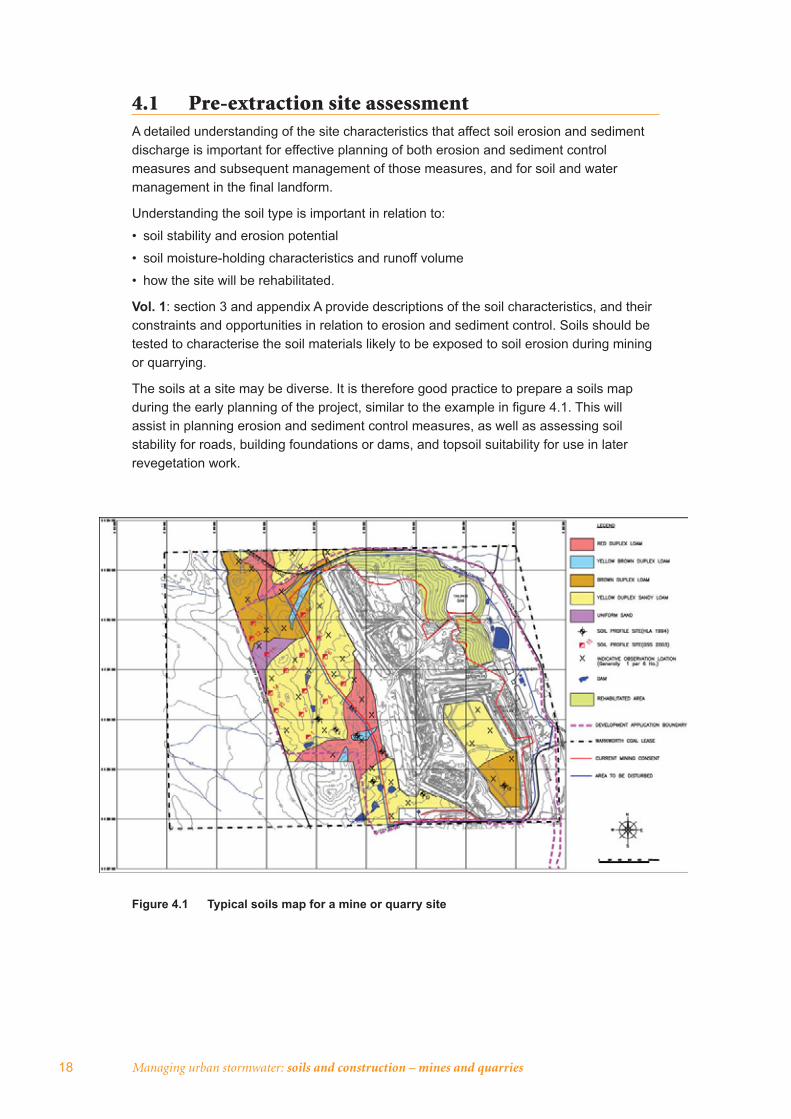
The soils at a site may be diverse. It is therefore good practice to prepare a soils map during the early planning of the project, similar to the example in fi gure 4.1. This will assist in planning erosion and sediment control measures, as well as assessing soil stability for roads, building foundations or dams, and topsoil suitability for use in later revegetation work.
Figure 4.1 Typical soils map for a mine or quarry site
Mine and quarry design 19
4.2 Final landform
4.2.1 Introduction It is important for operational soil and water management to consider at the beginning of the life of a mine or quarry the nature of the intended fi nal landform once operations have ceased. This ensures that control and management measures are an integral part of the site plan and design and provides an opportunity to identify the most cost-effective approaches to protecting the downstream environment from the effects of erosion and sedimentation. Several of the key issues for the fi nal landform are briefl y discussed below.
4.2.2 Final slope designSlope is the topographical factor with the greatest potential effect on soil erosion at a given location. The impacts of slope angle and length on soil loss are outlined in vol. 1:appendix A.
Importantly, the excavation of overburden usually results in:
• an increase in volume (~20–30%) of material to be managed on the site
• the placement of spoil piles above natural surface levels which subsequently causes an increase in surface elevation of the site.
This provides additional potential energy for rainfall and runoff to drive the erosion and deposition process.
The main soil and water management objective of reshaping is to produce slopes with gradients, lengths and shapes that are not prone to an unacceptable rate of erosion and are capable of conveying runoff from the newly created catchments without risk of erosion and sedimentation.
Any increase in runoff volume resulting from the fi nal landform can be managed by increasing the depth of fl ow or by increasing the velocity of fl ow, although the velocity should only be increased to a point that will not cause erosion. This point can easily be recognised in the fi eld where small rills or scour channels become evident.
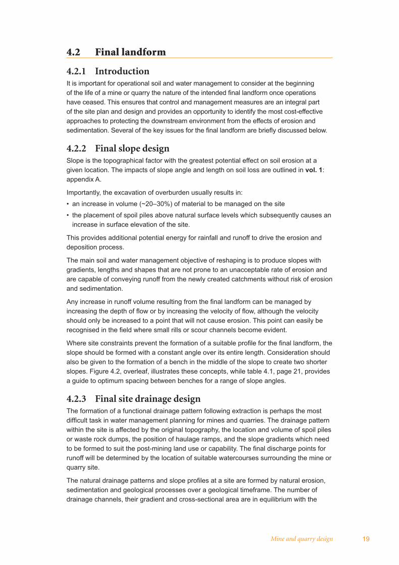
Where site constraints prevent the formation of a suitable profi le for the fi nal landform, the slope should be formed with a constant angle over its entire length. Consideration should also be given to the formation of a bench in the middle of the slope to create two shorter slopes. Figure 4.2, overleaf, illustrates these concepts, while table 4.1, page 21, provides a guide to optimum spacing between benches for a range of slope angles.
4.2.3 Final site drainage designThe formation of a functional drainage pattern following extraction is perhaps the most diffi cult task in water management planning for mines and quarries. The drainage pattern within the site is affected by the original topography, the location and volume of spoil piles or waste rock dumps, the position of haulage ramps, and the slope gradients which need to be formed to suit the post-mining land use or capability. The fi nal discharge points for runoff will be determined by the location of suitable watercourses surrounding the mine or quarry site.
The natural drainage patterns and slope profi les at a site are formed by natural erosion, sedimentation and geological processes over a geological timeframe. The number of drainage channels, their gradient and cross-sectional area are in equilibrium with the
20 Managing urban stormwater: soils and construction – mines and quarries
catchment area, soil type, slope, rainfall characteristics and vegetation. An alteration to any one of these parameters disturbs the equilibrium and can result in accelerated erosion and/or sedimentation of the drainage channels and downstream waterways.
Figure 4.2 Design of typical slope profiles (Source: Hannan 1995)
Preferred profile
20–30% 70–80%
Convex Concave
Average slope angle to suit proposed land use
Profile design when external features limit spreading distance
Back-sloped bench (minimum 4 m wide) constructed on the contour at about mid-point of slope
Average slope angle to suit land use (or land use modified to suit minimum attainable slope)
The best starting point for designing a drainage pattern is to determine the drainage density and stream ordering that existed on the site prior to mining. Drainage density is simply the catchment area (in m2) divided by the total length (metres) of all stream channels which drain the area. The resultant output is the average catchment per unit length of channel. An example of this relationship is:
Pre-mining catchment area = 216,000 m2 (21.6 hectares)
Total length of pre-mining drainage line = 920 metres
Drainage density = 216,000 m2 / 920m = 234 m2/m
For this example, the pre-mining drainage density of 234 m2/m means that every hectare within the catchment is being drained by 43 linear metres of drainage channel (i.e. 10,000 m2 divided by 234 m2/m = 43 metres).
The topography after extraction is unlikely to be identical to that which existed before mining. Overburden swell factors will result in a more elevated terrain with the average gradient, from the highest point on the reshaped surface to the fi nal discharge point on adjacent undisturbed land, steeper after extraction than before. The original drainage
Mine and quarry design 21
pattern, if reinstated, would therefore no longer be in equilibrium with its surroundings. To overcome this, the pre-extraction drainage density should be increased in the fi nal landform. Further guidance for planning modifi ed drainage systems for the post-extraction landform is provided in section 6.2.
Table 4.1 Bench spacing guide
Slope angle Recommended spacing between benches (metres)
< 6° Not necessary
6–8° 110
8–10° 100
10–12° 80
12–14 60
14–18° 40
18–20° 30
> 20°Use specialised erosion control measures
(e.g. hydromulching, straw mulching)
Source: Hannan (1995)
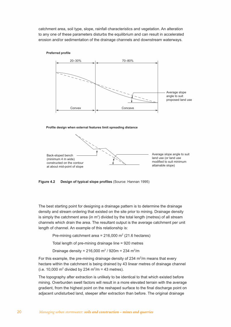
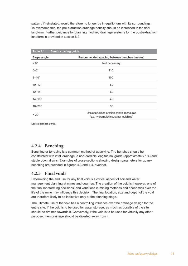
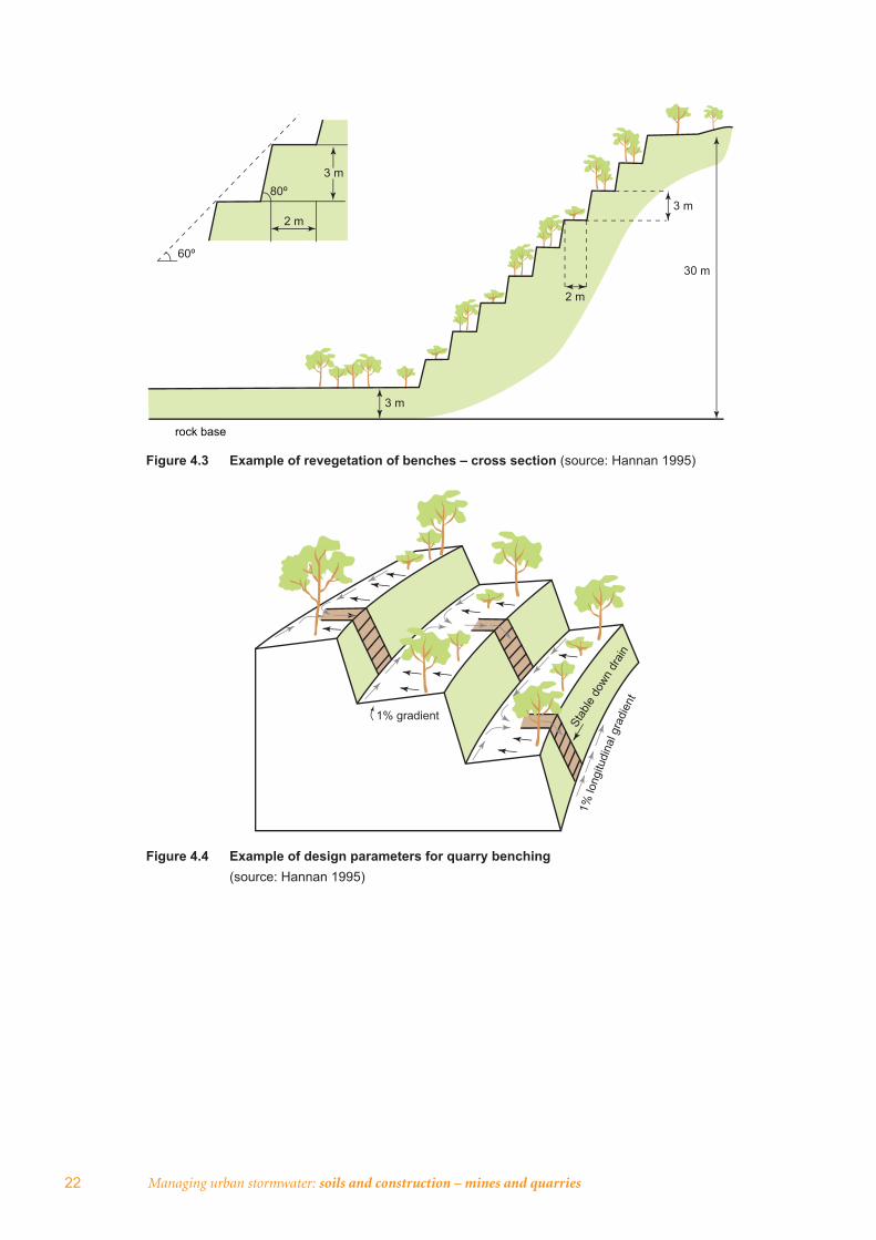
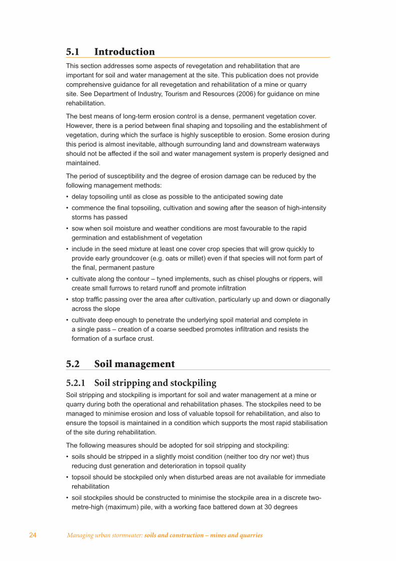
4.2.4 Benching Benching or terracing is a common method of quarrying. The benches should be constructed with infall drainage, a non-erodible longitudinal grade (approximately 1%) and stable down drains. Examples of cross-sections showing design parameters for quarry benching are provided in fi gures 4.3 and 4.4, overleaf.
4.2.5 Final voidsDetermining the end use for any fi nal void is a critical aspect of soil and water management planning at mines and quarries. The creation of the void is, however, one of the fi nal landforming decisions, and variations in mining methods and economics over the life of the mine may infl uence this decision. The fi nal location, size and depth of the void are therefore likely to be indicative only at the planning stage.
The ultimate use of the void has a controlling infl uence over the drainage design for the entire site. If the void is to be used for water storage, as much as possible of the site should be drained towards it. Conversely, if the void is to be used for virtually any other purpose, then drainage should be diverted away from it.
22 Managing urban stormwater: soils and construction – mines and quarries
1% gradient
Stab
le do
wn d
rain
1% lo
ngitu
dina
l gra
dien
t
Figure 4.3 Example of revegetation of benches – cross section (source: Hannan 1995)
Figure 4.4 Example of design parameters for quarry benching (source: Hannan 1995)
60º
80º
2 m
2 m
3 m
3 m
3 m
30 m
rock base
Mine and quarry rehabilitation 23
5. Mine and quarry rehabilitation
5.1 Introduction 24
5.2 Soil management 24
5.3 Revegetation type 25
5.4 Management and maintenance 27
24 Managing urban stormwater: soils and construction – mines and quarries
5.1 IntroductionThis section addresses some aspects of revegetation and rehabilitation that are important for soil and water management at the site. This publication does not provide comprehensive guidance for all revegetation and rehabilitation of a mine or quarry site. See Department of Industry, Tourism and Resources (2006) for guidance on mine rehabilitation.
The best means of long-term erosion control is a dense, permanent vegetation cover. However, there is a period between fi nal shaping and topsoiling and the establishment of vegetation, during which the surface is highly susceptible to erosion. Some erosion during this period is almost inevitable, although surrounding land and downstream waterways should not be affected if the soil and water management system is properly designed and maintained.
The period of susceptibility and the degree of erosion damage can be reduced by the following management methods:
• delay topsoiling until as close as possible to the anticipated sowing date
• commence the fi nal topsoiling, cultivation and sowing after the season of high-intensity storms has passed
• sow when soil moisture and weather conditions are most favourable to the rapid germination and establishment of vegetation
• include in the seed mixture at least one cover crop species that will grow quickly to provide early groundcover (e.g. oats or millet) even if that species will not form part of the fi nal, permanent pasture
• cultivate along the contour – tyned implements, such as chisel ploughs or rippers, will create small furrows to retard runoff and promote infi ltration
• stop traffi c passing over the area after cultivation, particularly up and down or diagonally across the slope
• cultivate deep enough to penetrate the underlying spoil material and complete in a single pass – creation of a coarse seedbed promotes infi ltration and resists the formation of a surface crust.
5.2 Soil management
5.2.1 Soil stripping and stockpilingSoil stripping and stockpiling is important for soil and water management at a mine or quarry during both the operational and rehabilitation phases. The stockpiles need to be managed to minimise erosion and loss of valuable topsoil for rehabilitation, and also to ensure the topsoil is maintained in a condition which supports the most rapid stabilisation of the site during rehabilitation.
The following measures should be adopted for soil stripping and stockpiling:
• soils should be stripped in a slightly moist condition (neither too dry nor wet) thus reducing dust generation and deterioration in topsoil quality
• topsoil should be stockpiled only when disturbed areas are not available for immediate rehabilitation
• soil stockpiles should be constructed to minimise the stockpile area in a discrete two-metre-high (maximum) pile, with a working face battered down at 30 degrees
Mine and quarry rehabilitation 25
• stockpiles should be trimmed, deep ripped to 500 millimetres, immediately sown with permanent pasture species, and fertilised.
It is also important that weeds are managed in pre-stripped areas, to avoid subsequent weed problems during rehabilitation.
Other recommended topsoil and stockpile handling procedures are described in vol. 1: section 4.3.2.
5.2.2 Managing soil conditionThe most common technique used to overcome spoil and waste-rock structural problems is to add a layer of topdressing material. However, pre-stripping of topsoil is not always benefi cial nor an improvement on overburden material. Alternatives include:
• the addition of organic mulches to improve soil structure – this will also aid microclimate, germination and infi ltration, and reduce runoff and evaporation. Biosolids are effective in improving soils, overburden and waste rock
• the application of gypsum to improve surface structure and improve water infi ltration. Artifi cial neutralisation of acidic soils with lime can also assist, but multiple liming applications should not be undertaken to avoid induced nutrient defi ciencies.
5.2.3 Topsoil applicationThe following measures should be considered when applying topsoil during rehabilitation:
• handle topsoil at an optimum moisture content to reduce damage to soil structure – this will provide a higher standard of revegetation and lower maintenance requirements
• re-spread topsoil in the reverse sequence to its removal so that the organic layer, containing any seed or vegetation, is returned to the surface
• spread topsoil at a minimum depth of 100 mm (or 50 mm in specifi c circumstances)
• spread topsoil along the contour of re-graded spoil by dumping at the top of slopes and grading downwards and across the contour – thus aiding runoff control, minimising erosion and increasing moisture retention
• level topsoil to an even surface, and avoid a compacted or over-smooth fi nish
• incorporate topsoil into the overburden or waste rock by contour cultivation with a tyned implement in preparation for sowing – this will leave the soil surface in a roughened condition creating a ‘key’ between the soil and the spoil
• stop any vehicle traffi c entering the area once topsoil is spread.
5.3 Revegetation typeRevegetation of areas which have been disturbed by mining and quarrying and subsequently reshaped is important for erosion control, aesthetics and returning the land to a useful condition. Very few disturbed areas will regenerate successfully without active management such as surface preparation, application of appropriate seed and fertiliser, and monitoring for several years.
Species are chosen for rehabilitation according to one or more of the following criteria:
• tolerance to site conditions such as moisture stress, heat stress, frost, wind blasting, substrate texture, toxicity, salinity, sodicity, alkalinity, acidity and nutrient defi ciencies
• site protection and erosion control of surface material
26 Managing urban stormwater: soils and construction – mines and quarries
• soil characteristics such as organic content, structure and aggregation, soil-water relationships, mobilising of nutrients, nitrogen fi xation and colonisation of soil organisms
• achievement of land-use management objectives and provision of amenity.
Vol. 1: section 7 and appendix G provide further guidance on revegetation.
5.3.1 Pasture establishmentFactors determining the method of establishing pasture include the confi guration, area, texture and stoniness of the reshaped surface, and species to be established. If the landscape approximates normal arable land, conventional equipment may be used. Broadcasting and drilling are common seeding methods (see vol. 1: section 7.2.2).
Where the surface is rough, as is the case with many post-mining and quarrying landforms, broadcasting is the only practical alternative. Aerial seeding may be used over large areas.
Hydroseeding is an option for spreading seed, soil ameliorants and surface protectants on land inaccessible to more conventional methods. However, it is an expensive method and will require a reliable water supply to be successful.
Valuable species may be planted by hand on selected sites in the form of roots or stolons.
Sowing rates for revegetation may need to be higher than for normal pasture establishment. Revegetation programs in the Hunter Valley coal mining industry, for example, often include sowing rates four times higher than normal for pasture, with the emphasis on higher initial cover requirements.
5.3.2 Tree establishmentThere are many benefi ts in having substantial timbered areas. The maintenance requirements of woodland or forest, for example, are less than pasture which requires more fertiliser input and longer-term management. Tree areas are also more resilient to drought and provide more diverse habitat for insects, birds and other fauna. Trees can also interact positively with spoil conditions, hydrology and geotechnical aspects of slopes.
To date, tree establishment on spoil has mainly been for visual and aesthetic purposes, although the ecological benefi ts for wildlife are becoming more widely acknowledged.
The single most signifi cant spoil parameter affecting tree growth is soil-water availability. The amount of water available can be maximised by simple practices such as deep ripping along the contour to provide a rough surface thus allowing more water to infi ltrate and less to run off.
The range of species trialled for both tree seeding and tree planting has been extensive with obvious variability in suitability between spoil types and climatic conditions. A more diverse range of species can usually be established through tree planting than through seeding.
Native tree and shrub species are normally sown at a total rate of four to six kilograms per hectare. Sowing rates for individual species vary depending on spoil or waste-rock type.
Initial tree/shrub densities are often high but decline quickly with age. Many of the shorter-lived Acacia species, for example, reach senescence and tree and shrub mortality increases as progressively larger trees compete with each other for soil moisture, light and other growth requirements. This process can be very benefi cial to the organic and nutrient status of the soil.
Mine and quarry rehabilitation 27
Direct seeding is generally not suitable where weed competition is severe. For this reason it is not routinely used on natural soils in mine buffer areas. In these areas, tree planting (e.g. in conjunction with weed mats / herbicide application) is more successful.
Trees are often planted with four-by-four metre spacing (625 per hectare). However, the optimal spacing will vary depending on the purpose – visual screening, habitat establishment, commercial forestry etc. – of the planting. An important factor that can affect spacing is the proportion of shrubs versus taller trees, and spacing can normally be reduced with increasing shrub content.
5.4 Management and maintenance
5.4.1 Vegetation managementFor a number of years after initial rehabilitation works, revegetated areas should be carefully managed to promote rapid growth and development in order to prevent degeneration of the site. Degeneration may result either in severe erosion and sedimentation, or replacement of the desirable sown species with weeds. On-going management will entail:
• monitoring of regrowth
• fertilising as necessary
• weed control
• re-ripping and re-sowing of bare areas.
It is diffi cult to avoid at least some sheet erosion and minor gully or rill erosion on sloping sites during the fi rst six to eight weeks between sowing and emergence of the new vegetation. The sediment and erosion control measures on the site should be operated and maintained in a proper and effi cient condition until the site is stabilised.
Larger bare areas may require re-ripping or some form of cultivation and complete re-sowing. If the topsoil has been completely removed by erosion, it should be replaced prior to cultivation.
5.4.2 Grazing and fencingGrazing of newly established pastures should not be contemplated for the fi rst two years, unless growth is unusually rapid. By this time, plants are strong enough to resist trampling and their root systems are suffi ciently developed to prevent plants being pulled completely out of the ground by grazing stock.
Initial grazing should consist of short periods (about seven to 10 days) at high stocking rates, at a time when the pasture is growing rapidly. This prevents selective grazing of the more palatable species that would otherwise favour the development of weeds. It also encourages plants to spread laterally, improving basal groundcover, which gives better erosion protection and fi re resistance.
Total groundcover should not be reduced below 70 per cent, as this will increase erosion hazard.

28
Erosion and sediment control techniques 29
6. Erosion and sediment cont rol te chniques
6.1 Applicable techniques from volume 1 30
6.2 Additional techniques 32
30 Managing urban stormwater: soils and construction – mines and quarries
6.1 Applicable techniques from volume 1Most of the erosion and sediment control techniques described in vol. 1 are applicable to erosion and sediment control for mines and quarries. Appendix F provides a summary of these techniques and guidance on their selection.
The main variation to the techniques described in vol. 1 relates to the sizing of diversion drains and sediment basins, to account for the greater longevity of mines and quarries relative to urban subdivision construction.
Due to the longer operational life of sediment control measures at mines and quarries, higher standards of design and construction should be adopted for water conveyance and storage structures, particularly those that will remain after the operational life of the mine.
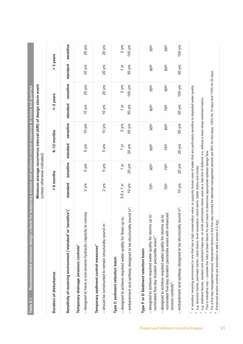
The recommended minimum design criteria for sediment control measures on mines and quarries are presented in table 6.1. Mine or quarry operators may adopt more stringent criteria, particularly if considered warranted by a site-specifi c environmental impact assessment. Table 6.2, overleaf, presents the indicative average annual sediment basin overfl ow (or spill) frequency for the various fi ve-day duration design storms presented in table 6.1.
Table 6.1 notes that the minimum basin design criteria can be reduced when enhanced erosion controls are used. Implementing enhanced erosion controls may be challenging for large mines or quarries. If enhanced controls are implemented, an independent audit of the implementation of enhanced controls should occur at least fortnightly for these sensitive sites. The auditor should be a soil conservationist or an accredited erosion control specialist.
The operation of basins for type F and D soils is described in vol. 1: section 6.3.4. This section notes that the basin should be drained or pumped out within the adopted management period following rainfall (commonly within a fi ve-day period). For the purposes of basin management, this requirement refers to rainfall of suffi cient depth to result in runoff entering the basin. This rainfall depth will vary depending on the site conditions at the time, particularly the extent of any impervious surfaces (e.g. road pavement) and the extent of any earlier rainfall. For sites at the bulk earthworks stage, where there has not been signifi cant preceding rainfall, rainfall depth of at least 5–10 mm may be needed before runoff commences.
This approach avoids the situation where the basin management period is extended for a further fi ve days following negligible rainfall (e.g. 1 mm). This would result in the basin containing runoff for a longer period, reducing its ability to capture runoff from subsequent storms and hence increasing the spill frequency.
Erosion and sediment control techniques 31
Tabl
e 6.
1 R
ecom
men
ded
min
imum
des
ign
crite
ria fo
r tem
pora
ry e
rosi
on a
nd s
edim
ent c
ontr
ol m
easu
res
at m
ines
and
qua
rrie
s
Min
imum
ave
rage
recu
rren
ce in
terv
al (A
RI)
of d
esig
n st
orm
eve
nt
(unl
ess
othe
rwis
e in
dica
ted)
Dur
atio
n of
dis
turb
ance
< 6
mon
ths
6–12
mon
ths
1–3
year
s>
3 ye
ars
Sens
itivi
ty o
f rec
eivi
ng e
nviro
nmen
t (‘s
tand
ard’
or ‘
sens
itive
’)1st
anda
rdse
nsiti
vest
anda
rdse
nsiti
vest
anda
rdse
nsiti
vest
anda
rdse
nsiti
ve
Tem
pora
ry d
rain
age
(ero
sion
) con
trol
s2
– de
sign
ed to
hav
e a
non-
eros
ive
hydr
aulic
cap
acity
to c
onve
y2
yrs
5 yr
s5
yrs
10 y
rs10
yrs
20 y
rs20
yrs
20 y
rs
Tem
pora
ry s
edim
ent c
ontr
ol m
easu
res3
– sh
ould
be
cons
truct
ed to
rem
ain
stru
ctur
ally
sou
nd in
:2
yrs
5 yr
s5
yrs
10 y
rs10
yrs
20 y
rs20
yrs
20 y
rs
Type
C s
edim
ent r
eten
tion
basi
n
– de
sign
ed to
ach
ieve
requ
ired
wat
er q
ualit
y fo
r fl o
ws
up to
:
– em
bank
men
t and
spi
llway
des
igne
d to
be
stru
ctur
ally
sou
nd in
4 :
0.5
x 1
yr1
yr
1 yr
2 yr
s1
yr2
yrs
1 yr
2 yr
s
10 y
rs20
yrs
20 y
rs50
yrs
50 y
rs10
0 yr
s50
yrs
100
yrs
Type
F o
r D S
edim
ent r
eten
tion
basi
n
– de
sign
ed to
ach
ieve
requ
ired
wat
er q
ualit
y fo
r sto
rms
up to
no
min
ated
fi ve
-day
dur
atio
n pe
rcen
tile
even
t:5
– de
sign
ed to
ach
ieve
requ
ired
wat
er q
ualit
y fo
r sto
rms
up to
no
min
ated
fi ve
-day
dur
atio
n pe
rcen
tile
even
t with
enh
ance
d
eros
ion
cont
rols
6 :
– em
bank
men
t and
spi
llway
des
igne
d to
be
stru
ctur
ally
sou
nd in
4 :
75th
80th
80th
85th
80th
85th
90th
95th
75th
75th
75th
80th
75th
80th
90th
95th
10 y
rs20
yrs
20 y
rs50
yrs
50 y
rs10
0 yr
s50
yrs
100
yrs
1A
‘sen
sitiv
e’ re
ceiv
ing
envi
ronm
ent i
s on
e th
at h
as a
hig
h co
nser
vatio
n va
lue,
or s
uppo
rts h
uman
use
s of
wat
er th
at a
re p
artic
ular
ly s
ensi
tive
to d
egra
ded
wat
er q
ualit
y.2
e.g.
div
ersi
on b
anks
, per
imet
er b
anks
, cat
ch d
rain
s, le
vel s
prea
ders
, che
ck d
ams,
bat
ter d
rain
s an
d ch
utes
.3
e.g.
sed
imen
t fen
ces,
sta
cked
rock
sed
imen
t tra
ps e
tc. o
n sm
all c
atch
men
ts w
here
use
d as
a ‘l
ast l
ine
of d
efen
ce’ (
i.e. w
ithou
t a d
own-
slop
e se
dim
ent b
asin
).4
This
is in
dica
tive
only
– c
onsi
der t
he ri
sks
of b
asin
failu
re fo
r eac
h ba
sin
to d
eter
min
e ap
prop
riate
spi
llway
des
ign
fl ow
.5
For a
fi ve
-day
man
agem
ent p
erio
d. A
djus
tmen
t fac
tors
to th
e fi v
e-da
y vo
lum
es fo
r alte
rnat
e m
anag
emen
t per
iods
are
85%
for t
wo-
days
, 125
% fo
r 10
days
and
170
% fo
r 20
days
.6
Enh
ance
d er
osio
n co
ntro
ls a
re d
escr
ibed
on
vol.1
sec
tion
6.3.
4(g)
.
32 Managing urban stormwater: soils and construction – mines and quarries
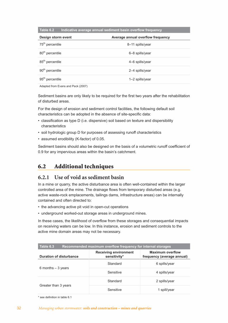
Table 6.2 Indicative average annual sediment basin overfl ow frequency
Design storm event Average annual overfl ow frequency
75th percentile 8–11 spills/year
80th percentile 6–8 spills/year
85th percentile 4–6 spills/year
90th percentile 2–4 spills/year
95th percentile 1–2 spills/year
Adapted from Evans and Peck (2007)
Sediment basins are only likely to be required for the fi rst two years after the rehabilitation of disturbed areas.
For the design of erosion and sediment control facilities, the following default soil characteristics can be adopted in the absence of site-specifi c data:
• classifi cation as type D (i.e. dispersive) soil based on texture and dispersibility characteristics
• soil hydrologic group D for purposes of assessing runoff characteristics
• assumed erodibility (K-factor) of 0.05.
Sediment basins should also be designed on the basis of a volumetric runoff coeffi cient of 0.9 for any impervious areas within the basin’s catchment.
6.2 Additional techniques
6.2.1 Use of void as sediment basinIn a mine or quarry, the active disturbance area is often well-contained within the larger controlled area of the mine. The drainage fl ows from temporary disturbed areas (e.g. active waste-rock emplacements, tailings dams, infrastructure areas) can be internally contained and often directed to:
• the advancing active pit void in open-cut operations
• underground worked-out storage areas in underground mines.
In these cases, the likelihood of overfl ow from these storages and consequential impacts on receiving waters can be low. In this instance, erosion and sediment controls to the active mine domain areas may not be necessary.
Table 6.3 Recommended maximum overfl ow frequency for internal storages
Duration of disturbanceReceiving environment
sensitivity*Maximum overfl ow
frequency (average annual)
6 months – 3 yearsStandard 6 spills/year
Sensitive 4 spills/year
Greater than 3 yearsStandard 2 spills/year
Sensitive 1 spill/year
* see defi nition in table 6.1

Erosion and sediment control techniques 33
Water-balance modelling with a daily time-step over a reasonable period (e.g.10 years with average wet and dry rainfall years) should be carried out to estimate the likely average annual overfl ow frequency from the internal storage. If the overfl ow frequency is less than that noted in table 6.3, sediment basins will not be necessary as the overfl ow frequency will be lower than that achieved by the sediment basin design criteria noted in table 6.1.
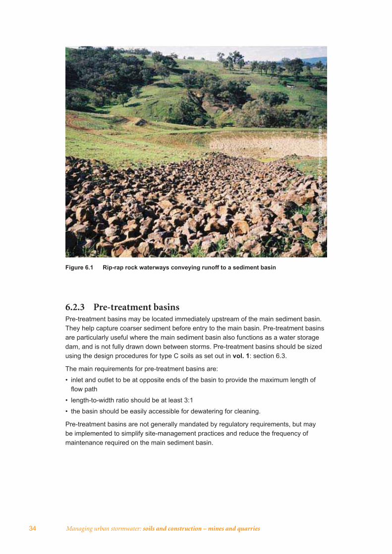
6.2.2 Channel lining using rip rap A preferred method of stabilising the bed of steep channels is using graded durable rip rap (rock) overlying a one-metre-deep base of stabilised and well-compacted material (fi gure 6.1 overleaf). Rip rap should not be single-sized, but should be a well-graded mixture designed to ensure that all gaps between large rocks are fi lled with rock of progressively smaller size so that no signifi cant voids occur in the rip-rap blanket. This arrangement means that underlying material can’t be washed out and creates an interlocking mass of rock to prevent movement of the rip rap down the channel. Grading recommendations are provided in table 6.4.
Steep waterways requiring rip-rap lining are not recommended in rehabilitation landscape design.
Rock for rip rap should be hard, tough and durable with a crushing strength of at least 25 MPa. The rock should be free of defi ned cleavage planes and should not be adversely affected by repeated wetting and drying. Rock should preferably be predominantly angular in shape with not more than 25 per cent of rocks, distributed through the gradation, having a length more than twice the breadth and thickness. No rock should have a length exceeding 2.5 times its breadth or thickness.
Where rock fails to meet this specifi cation it may still be used in some cases at the designer’s discretion, provided allowance is made in the design for its shortcomings. Care should be taken in attempting to source rock from within the landfi ll site as site rock may have insuffi cient durability and strength (e.g. mudstones and shales) and will therefore degrade over a relatively short time.
The use of geotextile fi lter cloth between the rip rap and the parent material can be considered in certain circumstances. Maximum resistance between the rip rap and the cloth is required. This can be achieved by:
• ensuring preparation of the bank to a rough and uneven batter before placing the cloth
• not stretching cloth tightly over the underlying bank
• avoiding cloths with low friction surfaces.
Specialist geotechnical advice should be sought to avoid rock sliding on the fi lter cloth.
Table 6.4 Rip-rap grading recommendations
Equivalent spherical diameter1 Per cent (by weight) of rip rap of smaller size
1.5–2.0 times D502 100%
D50 50%
0.3 D50 10–20%
1 The diameter of a sphere with an equivalent volume to the individual rock.2 D50 is the medium rip-rap diameter of the rock mix (i.e. 50% by weight is smaller than this size).
Source: Department of Land and Water Conservation (1999)
34 Managing urban stormwater: soils and construction – mines and quarries
Figure 6.1 Rip-rap rock waterways conveying runoff to a sediment basin
© G
Sum
mer
haye
s/D
epar
tmen
t of P
rimar
y In
dust
ries
6.2.3 Pre-treatment basinsPre-treatment basins may be located immediately upstream of the main sediment basin. They help capture coarser sediment before entry to the main basin. Pre-treatment basins are particularly useful where the main sediment basin also functions as a water storage dam, and is not fully drawn down between storms. Pre-treatment basins should be sized using the design procedures for type C soils as set out in vol. 1: section 6.3.
The main requirements for pre-treatment basins are:
• inlet and outlet to be at opposite ends of the basin to provide the maximum length of fl ow path
• length-to-width ratio should be at least 3:1
• the basin should be easily accessible for dewatering for cleaning.
Pre-treatment basins are not generally mandated by regulatory requirements, but may be implemented to simplify site-management practices and reduce the frequency of maintenance required on the main sediment basin.
Erosion and sediment control techniques 35
6.2.4 Manual ‘batch’ treatment within the retention pond using a fl occulant
This approach may be used to reduce elevated levels of total suspended solids in captured runoff.
Vol. 1: appendix E identifi es potential fl occulating agents that may be used in the treatment of sediment-laden stormwater. Gypsum is commonly used at urban construction sites due to its low potential for toxicity (e.g. accidental overdosing) in receiving waterways. Gypsum, however, is not a very effective fl occulating agent and high doses are required to ensure that the minimum concentration needed for fl occulation is achieved throughout a sediment retention basin. Because of the chemical and labour costs, this approach has limited value as a long-term treatment strategy for landfi ll sites.
Alternative fl occulants may be used at landfi ll sites, although their use will require appropriate investigation and design to ensure that the treatment system includes suitable safeguards to protect the receiving environment from the potential impact of such chemicals.
6.2.5 Using a purpose-designed treatment system This is another approach for reducing elevated levels of total suspended solids in captured runoff.
Vol. 1: appendix E provides details of a simple automatic system for adding fl occulant to the infl ow into a sediment basin. While such a system could be warranted on smaller sites or sites that have limited opportunity for on-site water reuse, the addition of fl occulant to all water entering a sediment basin is likely to be wasteful of chemicals (and therefore incur additional costs), especially in situations where most of the water is to be reused within the landfi ll site.
Two types of systems may be considered for application at mine and quarry sites:
• a batch treatment system in which a quantity of sediment-laden water is discharged into a separate settlement pond for treatment and subsequent discharge after settlement
• permanent ‘fl ow-through’ treatment systems involving purpose-built or commercial ‘off-the-shelf’ chemical injection and fl occulation facilities, which may include conventional sedimentation and drying beds.
These approaches use conventional water treatment processes involving the addition of a fl occulant, creating conditions for fl oc growth and then removing the fl oc by some process (e.g. tangential fl ow separator or conventional sedimentation in ponds). Although such systems have a signifi cant initial cost, they are likely to be more cost-effective in the long term because of reduced chemical costs, reduced labour and greater reliability of discharge quality. Schemes for some coal mines include on-site real-time monitoring of runoff fl ow with dosing of cationic coagulant to runoff streams up to the design criterion.
The main design issues that arise with such a treatment system are:
• the chemicals to be used for fl occulation (and pH correction if necessary)
• design treatment rate
• any required volume of balancing storage.
Many mines contain and manage large volumes of saline or acidic water. This water can be a useful tool to fl occulate dispersive clays out of water for batch water treatment prior to controlled reuse or off-site release. This applies particularly if the mine has approval to discharge saline water.
36 Managing urban stormwater: soils and construction – mines and quarries
It is desirable to have a minimal size treatment plant that operates continually at a steady rate. However, the episodic nature of runoff means that either a large buffering storage is required to allow such a system to operate or that chemicals are dosed in proportion to the infl uent fl ow rate. In practice, continuous treatment is unrealistic because of the large buffering storage capacity required. A typical practical design is one which is required to operate for 60 to 240 days a year depending on the rainfall. Such a system may require an ‘off-line’ balancing storage to allow it to operate in an optimal manner.
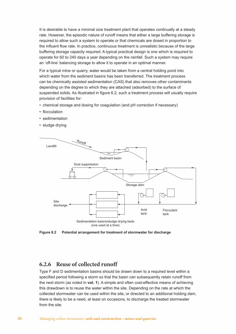
For a typical mine or quarry, water would be taken from a central holding pond into which water from the sediment basins has been transferred. The treatment process can be chemically assisted sedimentation (CAS) that also removes other contaminants depending on the degree to which they are attached (adsorbed) to the surface of suspended solids. As illustrated in fi gure 6.2, such a treatment process will usually require provision of facilities for:
• chemical storage and dosing for coagulation (and pH correction if necessary)
• fl occulation
• sedimentation
• sludge drying.
Figure 6.2 Potential arrangement for treatment of stormwater for discharge
Sediment basin
Landfill
Dust suppression
Storage dam
Site discharge
Acid tank
Flocculant tank
Sedimentation basins/sludge drying beds (one used at a time)
Runoff
6.2.6 Reuse of collected runoffType F and D sedimentation basins should be drawn down to a required level within a specifi ed period following a storm so that the basin can subsequently retain runoff from the next storm (as noted in vol. 1). A simple and often cost-effective means of achieving this drawdown is to reuse the water within the site. Depending on the rate at which the collected stormwater can be used within the site, or directed to an additional holding dam, there is likely to be a need, at least on occasions, to discharge the treated stormwater from the site.
Erosion and sediment control techniques 37
On a typical mine or quarry, there are a number of common uses where the runoff water quality is compatible with uses such as dust suppression, fi refi ghting, process water and irrigation of rehabilitated areas. For irrigation of captured runoff, the application rate will be limited by the:
• hydraulic loading considerations of the irrigation area
• evapo-transpiration needs of the vegetation on the irrigation area
• water-quality needs for the proposed use (e.g. salinity levels should be considered when irrigating rehabilitation vegetation).
Where a sediment basin also functions as a water storage for runoff prior to reuse, the capacity of a basin designed for type D or F soils should normally be the sum of the:
• required settling volume, based on the adopted design storm volume and management period, where infl ows will be treated and discharged
• sediment storage volume
• capacity required for water reuse.
This ensures that suffi cient volume is available in the basin to capture runoff from storms up to the design event without overtopping. Such storages should be operated so that the storage is drawn down to the storage zone level within the adopted management period after the end of a storm, such that the basin can subsequently retain runoff from the next rainfall event.
For basins providing storage for reuse, runoff treatment and discharge will not be required where the runoff reused over the adopted basin management period (e.g. fi ve days) is greater than the settling volume. In this situation, the basin’s settling volume will be emptied within the basin management period through reuse rather than discharge. The basin will need to be designed with a reuse volume greater than or equal to the settling volume.
The requirements of the Dam Safety Act 1978 may apply to large water storage dams.
Managing urban stormwater: harvesting and reuse (DEC 2006) provides guidance on stormwater reuse.
38 Managing urban stormwater: soils and construction – mines and quarries
Bibliography
Australian and New Zealand Environment and Conservation Council (ANZECC) and Agricultural and Resource Management Council of Australia and New Zealand (ARMCANZ) 2000. Australian and New Zealand guidelines for fresh and marine water quality, Canberra.
Department of Environment and Climate Change NSW (DECC) 2008a. Managing urban stormwater: soils and construction, volume 2A: installation of services, Sydney.
Department of Environment and Climate Change NSW (DECC) 2008b. Managing urban stormwater: soils and construction, volume 2C: unsealed roads, Sydney.
Department of Environment and Conservation NSW (DEC) 2004. EPA prosecution guidelines, Sydney.
Department of Environment and Conservation NSW (DEC) 2006. Managing urban stormwater: harvesting and reuse, Sydney.
Department of Industry, Tourism and Resources 2006. Leading practice sustainable development program for the mining industry – mine rehabilitation, Australian Government, Canberra.
Department of Land and Water Conservation NSW 1999. Draft guidelines for establishing stable drainage lines on rehabilitated minesites (unpublished).
Department of Natural Resources NSW (DNR) 2003. Watercourse and riparian zone rehabilitation requirements (version 3), Sydney.
Department of Primary Industries NSW (DPI) 2006. Guidelines to the mining, rehabilitation and environmental management process, version 3.
Department of Urban Affairs and Planning (DUAP) 2000. EIS guideline: coal mines and associated infrastructure.
Environment Australia 1999. Best practice environmental management in mining – water management, Department of the Environment and Heritage, Canberra.
Environment Protection Agency (Commonwealth) 2005. Best practice environmental management in mining: tailings management, Canberra.
Evans and Peck 2007. Sediment basin performance, fi nal report to NSW Roads and Traffi c Authority, Sydney.
Hannan, JC 1995. Mine rehabilitation – a handbook for the coal mining industry,2nd edition, NSW Coal Association, Sydney.
Institution of Engineers Australia 1987. Australian rainfall and runoff, volume 2.
Institution of Engineers Australia 1997. Australian rainfall and runoff, volume 1 (revised).
Landcom 2004a. The hip pocket handbook, Sydney.
Landcom 2004b. Managing urban stormwater: soils and construction, volume 1, 4th edition, Sydney.
Planning NSW 1996a. EIS guideline: extractive industries – dredging and other extraction in riparian and coastal areas.
Planning NSW 1996b. EIS guideline: extractive industries – quarries.
Appendices 39
App endices
Appendix A: Types of mining-related activity 40
Appendix B: Threshold criteria for scheduled activities 43
Appendix C: Erosion and sediment control planning 44
Appendix D: Sample ESCP for small quarry 46
Appendix E: Sample ESCP for large mine 50
Appendix F: Selection of control measures 69
40 Managing urban stormwater: soils and construction – mines and quarries
Appendix A: Types of mining-related activity
A.1 Exploration activityExploration activities often include access to a remote site where drilling is undertaken to assess sub-surface geological conditions and the extent of mineral resources. Water is often used in the drilling process and small water-management sumps and controls are required to prevent the discharge of sediment to receiving waters.
Exploration is usually a staged process involving preliminary drilling followed by numerous detailed investigations once a resource is detected. While the search for more data often involves multiple drilling sites and sometimes hundreds of holes, the area disturbed tends to be small and so erosion and sediment controls are reasonably basic.
Access tracks to exploration sites and borehole transect clearing lines will cause additional disturbance to the landscape.
A.2 Underground minesUnderground mining operations extract minerals from deep ore bodies and coal deposits that are uneconomical or not feasible by means such as surface mining. There are many different methods used in underground mining. The appropriate method will usually be selected after considering whether the coal seam or ore body will be developed through shafts or through inclines, or a combination of both. Other factors involved are the depth of the deposit, time available for the development, the cost and the choice of haulage methods out of the mine.
Underground mining generally has less impact on the land surface relative to surface extraction. Potential impacts include mine subsidence, which may impact on surface water or groundwater fl ows. Underground mines usually include surface facilities, such as a material stockpiles, which require appropriate soil and water management strategies.
The key soil and water aspects for underground mining are primarily associated with subsidence impacts, groundwater management and waste management (tailings, coarse reject, waste rock etc.). Consideration should be given to soil and water management within the pit-top areas.
A.3 Surface extractionSurface mining techniques are used in many coal and metalliferous operations as well as hard and soft rock quarrying. They are often large-scale developments. Surface operations entail the open-face extraction (e.g. by terracing or strip mining) of reasonably shallow resources, compared to underground mining of deep seams or ore bodies. Surface extraction typically involves:
• clearing of areas to be quarried or mined, and stripping of topsoil for reuse in rehabilitation
• drilling and blasting of ‘overburden’ (material overlying the target resource)
• loading of overburden for relocation to a ‘waste dump’
• subsequent recovery and loading of the extracted material into trucks for transport to processing facilities that vary with the type of mineral being extracted.
Waste materials from preparation, milling and processing plants are carefully managed according to their characteristics for fi nal treatment, placement, encapsulation or disposal.
Appendix A: Types of mining-related activity 41
Surface mining, by its nature, causes signifi cant alteration to topography and catchment hydrology. Signifi cant environmental management challenges include:
• surface-water drainage issues (including fl ooding) in the active pit and haul roads areas, shaped and unshaped overburden dumps, and high and low wall areas
• clean and ‘dirty’ water management systems
• diversion of creeks and tributaries
• tailings dams.
Stable post-mining or quarrying landforms are also an important soil and water management issue for surface extraction operations.
A.4 Mineral sand miningMineral sand mining is a specifi c type of open-cut mining that extracts valuable heavy minerals, particularly titanium and zircon, typically from coastal or sedimentary basin sand deposits. Zircon and rutile are the most commonly extracted mineral sand compounds in New South Wales, although ilmenite and monazite are also extracted from coastal sands.
Coastal mineral sand mining often uses a fl oating dredge and concentrator process. Continuous backfi lling of the mined area with bulk sand residues occurs as part of the mining process. The waste sand is re-deposited to form a landscape similar to the pre-mining topography.
Mineral sand mining often occurs over a relatively short timeframe, usually less than 10 years per site. Within this timeframe there are many areas that are re-established in the initial years after mining.
Coastal sand mining is conducted close to littoral and foreshore sand dune environments. Soil and water management issues associated with mineral sand mining include:
• landform stability (e.g. tailings dam stacking methods to avoid land slips, particularly in mining of high dunes)
• foredune protection
• high watertable limitations
• conservation of minimal topsoil reserves and local seed
• appropriate revegetation species selection.
A.5 Waste dumpsSome activities or work areas on mine and quarry sites require special consideration from an erosion and sediment control perspective.
Waste dumps consist of unrecoverable or undesired residual material from a mining process and may include overburden material from open-cut coal mines and waste rock dumps from metalliferous sites.
In many cases, particularly where the material has received minimal processing or is inert, it can be returned to its origin (e.g. the pit). However, it often requires relocation to an appropriate emplacement area and subsequent reshaping into a stable fi nal landform and/or capping. Some materials may require additional chemical and biochemical controls (e.g. for acid mine drainage). Erosion and sediment control on dump surfaces, particularly batters, and vegetation establishment on relatively steep slopes are signifi cant factors affecting the long-term surface stability of waste dumps.
42 Managing urban stormwater: soils and construction – mines and quarries
A.6 Tailings facilitiesMineral processing plants produce both coarse-grained wastes (‘reject’) and fi ne-grained waste fractions referred to as tailings. Tailings can contain signifi cant concentrations of potential pollutants, including minerals that are not amenable to recovery at the time of initial mining. Tailings are often pumped as a slurry and disposed of in specially lined tailings dams, which are bunded and eventually capped and revegetated to prevent the release of environmentally harmful materials. All tailings disposal systems require careful management of the water component. Tailings management is specialised and this publication does not address it in any detail. For information on tailings management see Environment Protection Agency (2005).
A.7 Mine infrastructure areasThe surface infrastructure associated with different types of mining and quarrying varies considerably, but may include ancillary activities such as administration centres, potable water-treatment plants, internal haulage and access roads, workshops and maintenance plants, material handling and preparation plants, product stockpile areas, bulk fuel and chemical storage areas, on-site sewage treatment plants, noise control and visual screen bunds, and electricity substations. These areas also require effective management to separate clean and dirty water, contain contaminated runoff, and manage site drainage and revegetation (other than hardstand areas).

Appendix B: Threshold criteria for scheduled activities 43
Appendix B: Threshold criteria for scheduled activities Threshold criteria from schedule 1 of the Protection of the Environment Operations Act 1997 defi ne activities that require an environment protection licence issued by DECC on behalf of the Environment Protection Authority.
B.1 Extractive industries These include industries that:
• obtain extractive materials by methods including excavating, dredging, blasting, tunnelling or quarrying, or that store, stockpile or process extractive materials
• obtain, process or store for sale or reuse an intended quantity of more than 30,000 cubic metres per year of extractive material.
B.2 Dredging works Dredging works are those in which materials of more than 30,000 cubic metres per year are obtained from the bed, banks or foreshores of any waters.
B.3 Mines Mines that mine, process or handle minerals (being minerals within the meaning of the Mining Act 1992 other than coal) and that have disturbed, are disturbing or will disturb a total surface area of more than four hectares of land associated with a mining lease or mineral claim or subject to a section 8 notice under the Mining Act 1992 by:
• clearing or excavating
• constructing dams, ponds, drains, roads, railways or conveyors, or
• storing or depositing overburden, ore or its products or tailings.
B.4 Coal mines Coal mines are those that mine, process or handle coal and are underground or open-cut mines that:
• have an intended production or processing capacity of more than 500 tonnes per day of coal or carbonaceous material, or
• have disturbed, are disturbing or will disturb a total surface area of more than four hectares of land by:
• clearing or excavating
• constructing dams, ponds, drains, roads, railways or conveyors, or
• storing or depositing overburden, coal or carbonaceous material or tailings.
44 Managing urban stormwater: soils and construction – mines and quarries
Appendix C: Erosion and sediment control planningThe strategy for controlling surface erosion and sediment discharge can be documented in an ESCP as noted in section 3.4.
The nature and level of detail in an ESCP should refl ect the potential signifi cance of erosion and sediment control at the site. Plans may range from a brief, simple map with accompanying notes for a small site, to detailed and comprehensive plans for a complex or large development. Some form of ESCP is likely to be appropriate for all sites regardless of the scale of the development. Appendix D contains a sample ESCP for a small quarry, with appendix E including an ESCP for a large mine.
C.1 Preparation of the planThe planning and implementation of an erosion and sediment control strategy should be an integral part of the initial site development plan to ensure effective erosion and sediment control measures are included in each development sequence.
The following steps should be taken in the preparation of an ESCP for a mine or quarry:
• investigate the site characteristics
• prepare an extraction plan to assist with sequencing of erosion and sediment control measures
• integrate vegetation management with the proposed extraction plan
• determine existing and proposed drainage patterns
• select erosion control practices
• select sediment control practices
• outline the site-revegetation program.
C.2 Recommended content of ESCPAs described in vol. 1: section 3, ESCPs should contain:
• a map
• supporting documentation
• construction details and notes.
As noted previously, the specifi c content and level of detail required in an ESCP will vary according to the nature and type of activity, its environmental context and the existence and scope of other water-related management plans for the site. For a large operation, the above elements should be included in a mine or quarry ESCP. For a small mines or quarries, a subset of these elements is appropriate and the details of the ESCP can be scaled back.
C.3 The mapThis key component of the plan, generally prepared at a scale of 1:500 to 1:4000, should illustrate the following:
• locality of the mine or quarry site
• existing contours of the site, (preferably at 0.5–1.0 m contour interval) including catchment area boundaries
• location of existing vegetation
• location of critical natural areas requiring special planning or management (e.g. threatened species)
Appendix C: Erosion and sediment control planning 45
• stages of mining or extraction
• nature and extent of earthworks, including cut and fi ll
• location of all soil stockpiles
• location of proposed roads
• existing and proposed drainage patterns
• location and types of proposed erosion control measures
• location and type of proposed sediment control measures
• site-rehabilitation proposals, including fi nal contours.
C.4 Supporting documentationThe information on the map should be supported by information on the overall erosion and sediment control strategy for the site. The supporting information should provide a brief description of:
• site characteristics (slopes, topography etc.)
• major soil types present, including description and depth of each layer
• existing vegetation species
• any ‘vulnerable lands’ present
• catchment areas above and within the site including drainage patterns
• integration of vegetation management with the proposed extraction plan
• any areas within the site with serious erosion or sedimentation potential, together with details of special planning or management requirements proposed for their protection
• the construction sequence over the life of the development in the form of a chart or table outlining the sequence of works including erosion and sediment control measures
• the erosion control strategy including the criteria used to select, locate and schedule control measures
• measures to be used to control sediment on site including the criteria used to select, locate and schedule such measures
• the extraction program
• progressive rehabilitation
• the revegetation program including revegetation species
• the maintenance strategy for all control measures including the nomination of responsibility for follow-up maintenance of any permanent control measures.
46 Managing urban stormwater: soils and construction – mines and quarries
Appendix D: Sample ESCP for small quarry
D.1 Schedule of works
Stage one• Access roads
• Site clearance
• Diversion banks
• Topsoil stockpiling
• Overburden stockpiling
• Internal roads
• Erosion control works (permanent and temporary)
• Temporary revegetation (stockpiles)
• Permanent revegetation of works
• Extraction operation – stage one
• Maintenance program
• Rehabilitation of stage one commenced
Stage two• Site clearance (stage two)
• Diversion banks
• Reshape stage one
• Topsoil removed to (stage one)
• Overburden removed to (stage one)
• Revegetate (stage one)
• Construct internal roads
• Erosion and sediment control works (permanent and temporary)
• Maintenance program
• Extraction operation (stage two)
• Rehabilitation stage two commenced
Stage three• Site clearance
• Diversion banks
• Reshape (stage two)
• Topsoil removed (stage two)
• Overburden removed to (stage two)
• Internal roads
• Erosion and sediment control works (permanent and temporary)
• Revegetation (stage two)
• Maintenance program
• Extraction operation (stage three)

Appendix D: Sample ESCP for small quarry 47
• Extraction operation (stage three) complete
• Reshape (stage three)
• Replace overburden from (stage one)
• Replace topsoil from (stage one)
• Revegetate (stage three)
• Rehabilitation stages one, two and three complete
• Maintenance
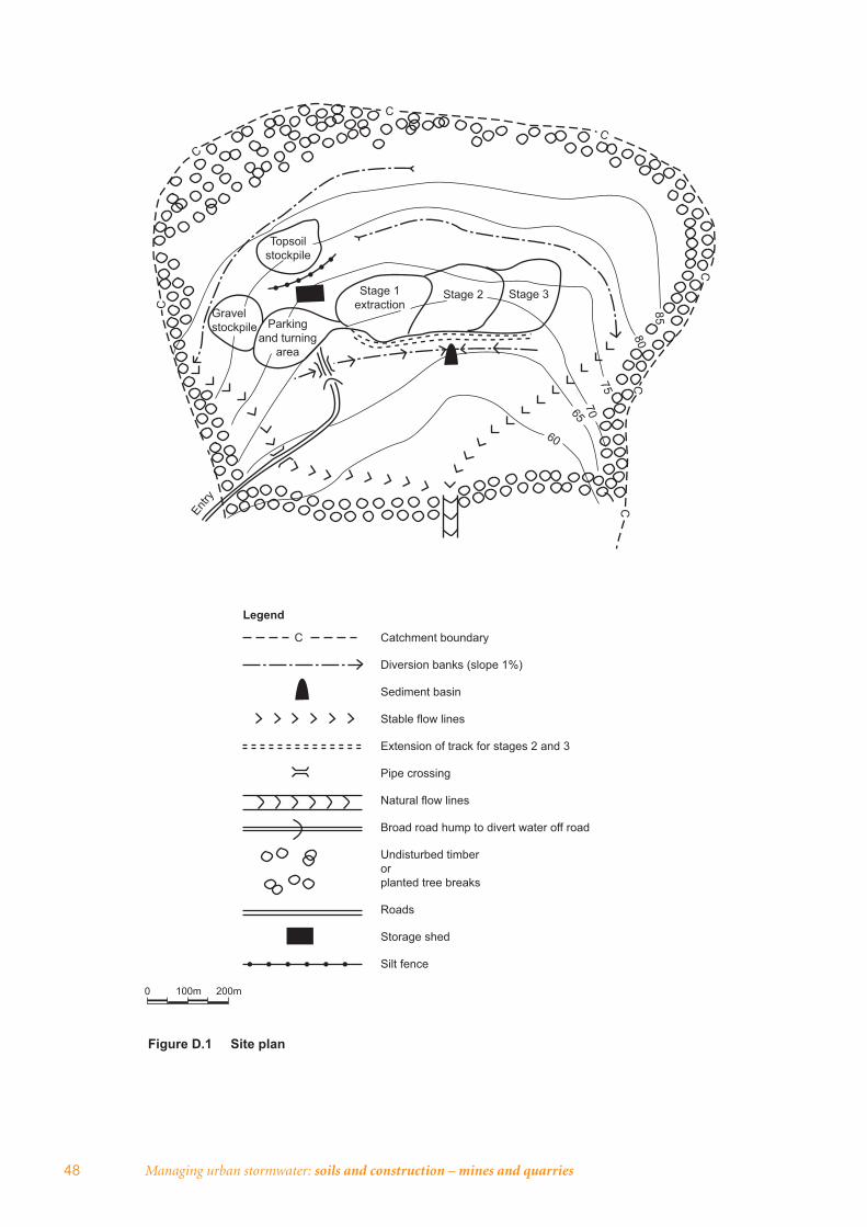
48 Managing urban stormwater: soils and construction – mines and quarries
Entry
Figure D.1 Site plan
Gravel stockpile Parking
and turning area
Stage 1extraction
Stage 2 Stage 3
Topsoilstockpile
C
C
C
CC
C
C
60
6570
75
8085
C Catchment boundary
Diversion banks (slope 1%)
Sediment basin
Stable flow lines
Extension of track for stages 2 and 3
Pipe crossing
Natural flow lines
Broad road hump to divert water off road
Undisturbed timber or planted tree breaks
Roads
Storage shed
Silt fence
0 100m 200m
Legend
Appendix D: Sample ESCP for small quarry 49
D.2 Commentary and construction notes• Construct access road with erosion control measures. Sow all distributed areas,
excluding road surface, with the following seed/fertiliser mixture:
• Couch grass 3 kg/ha (spring/summer)
• Ryegrass 20 kg/ha (autumn/winter)
• Starter R 15 or equivalent 100 kg/ha.
• Install pipe culverts, with headwalls, within the drainage line on the main access road.
• Selectively clear vegetation, with cleared vegetation windrowed on the contour for burning.
• Install diversion banks with 1 m base width, 0.3 m minimum depth and batter gradients to be no steeper than 1:3 (V:H).
• Sediment basin – settling zone volume of 2000 m3 and sediment storage zone volume of 1000 m3
• Open no more than 0.5 ha of quarry at any one time.
• Strip topsoil and overburden from stage, then stockpile and sow within 14 days with the following seed/fertiliser mixture:
• Oats/ryegrass 30 kg/ha (autumn/winter/early spring)
• Japanese millet 25 kg/ha (spring/summer)
• Couch 3 kg/ha (spring/summer)
• Starter R 15 or equivalent 250 kg/ha.
• Clearly delineate internal roads, work areas and all stockpiles and protect by erosion and sediment control works.
• Progressively install both temporary and permanent erosion and sediment control works per the erosion/sediment control schedule of works.
• At the completion of each extraction stage, progressively reshape, re-topsoil then revegetate all disturbed areas.
• Completely rehabilitate each extraction stage before the start of the next stage.
• Regularly inspect all sediment control structures for damage, and remove sediment to overburden site.
• Carry out ongoing maintenance including resowing/fertilising of areas as required.
Standard drawingsThe following standard drawings from vol. 1 (Landcom 2004) are applicable to the recommended erosion and sediment controls:
• Stockpiles SD 4-1
• Earth bank – high fl ows SD 5-6 (for all diversion banks)
• Temporary waterway crossing SD 5-1
• RECP concentrated fl ow SD 5-7 (for constructed fl ow lines downstream of level spreaders)
• Earth basin – wet SD 6-4 (for sediment basin)
• Sediment fence SD 6-8.
[Note: The standard drawings referred to here would be included in a full copy of the ESCP.]
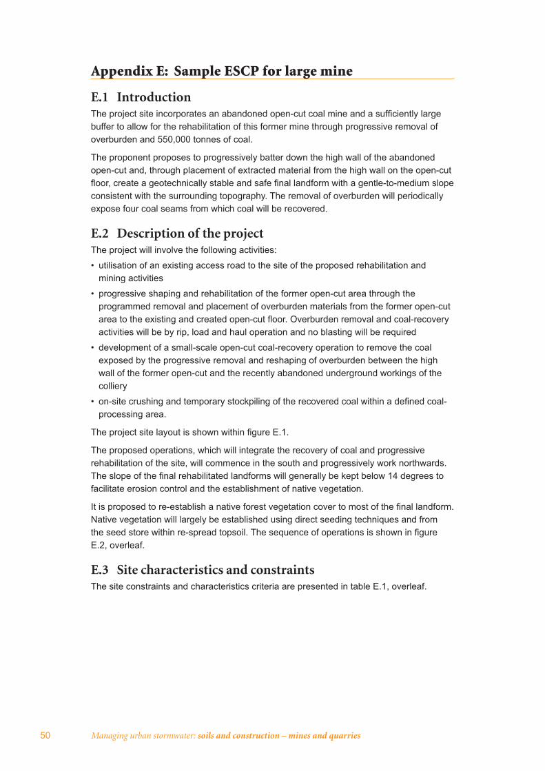
50 Managing urban stormwater: soils and construction – mines and quarries
Appendix E: Sample ESCP for large mine
E.1 IntroductionThe project site incorporates an abandoned open-cut coal mine and a suffi ciently large buffer to allow for the rehabilitation of this former mine through progressive removal of overburden and 550,000 tonnes of coal.
The proponent proposes to progressively batter down the high wall of the abandoned open-cut and, through placement of extracted material from the high wall on the open-cut fl oor, create a geotechnically stable and safe fi nal landform with a gentle-to-medium slope consistent with the surrounding topography. The removal of overburden will periodically expose four coal seams from which coal will be recovered.
E.2 Description of the projectThe project will involve the following activities:
• utilisation of an existing access road to the site of the proposed rehabilitation and mining activities
• progressive shaping and rehabilitation of the former open-cut area through the programmed removal and placement of overburden materials from the former open-cut area to the existing and created open-cut fl oor. Overburden removal and coal-recovery activities will be by rip, load and haul operation and no blasting will be required
• development of a small-scale open-cut coal-recovery operation to remove the coal exposed by the progressive removal and reshaping of overburden between the high wall of the former open-cut and the recently abandoned underground workings of the colliery
• on-site crushing and temporary stockpiling of the recovered coal within a defi ned coal-processing area.
The project site layout is shown within fi gure E.1.
The proposed operations, which will integrate the recovery of coal and progressive rehabilitation of the site, will commence in the south and progressively work northwards. The slope of the fi nal rehabilitated landforms will generally be kept below 14 degrees to facilitate erosion control and the establishment of native vegetation.
It is proposed to re-establish a native forest vegetation cover to most of the fi nal landform. Native vegetation will largely be established using direct seeding techniques and from the seed store within re-spread topsoil. The sequence of operations is shown in fi gure E.2, overleaf.
E.3 Site characteristics and constraintsThe site constraints and characteristics criteria are presented in table E.1, overleaf.
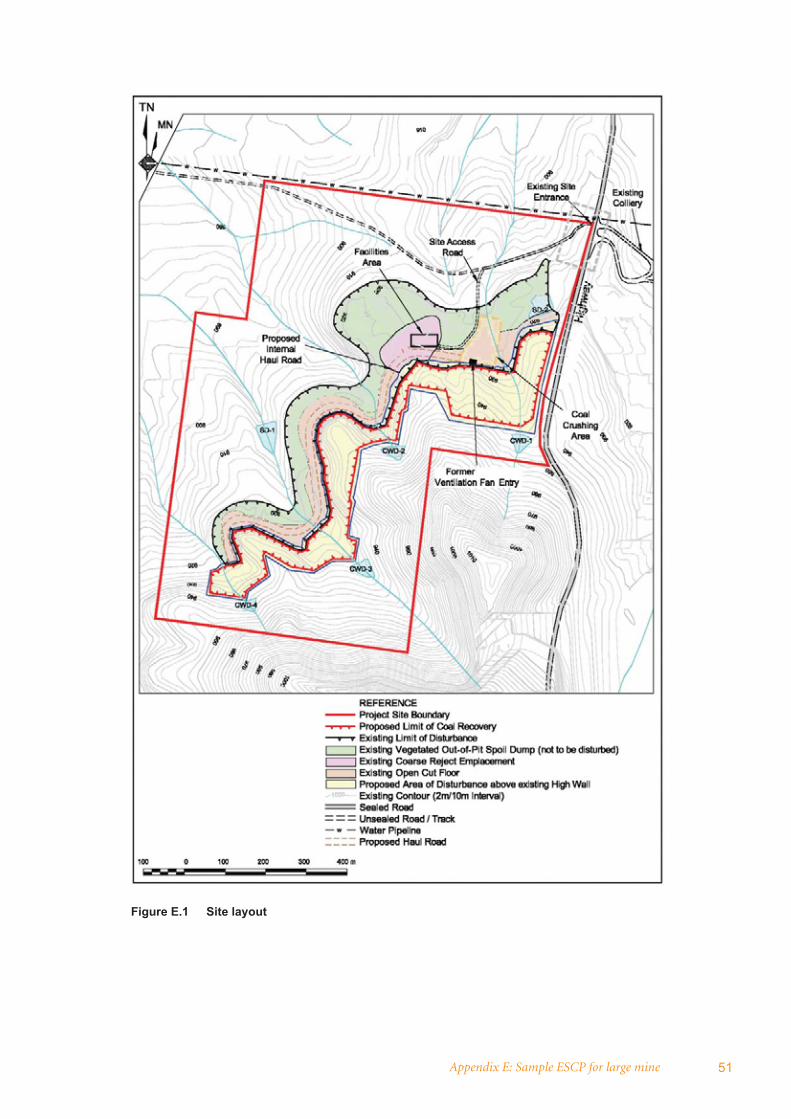
Appendix E: Sample ESCP for large mine 51
Figure E.1 Site layout
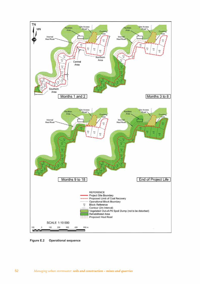
52 Managing urban stormwater: soils and construction – mines and quarries
Figure E.2 Operational sequence
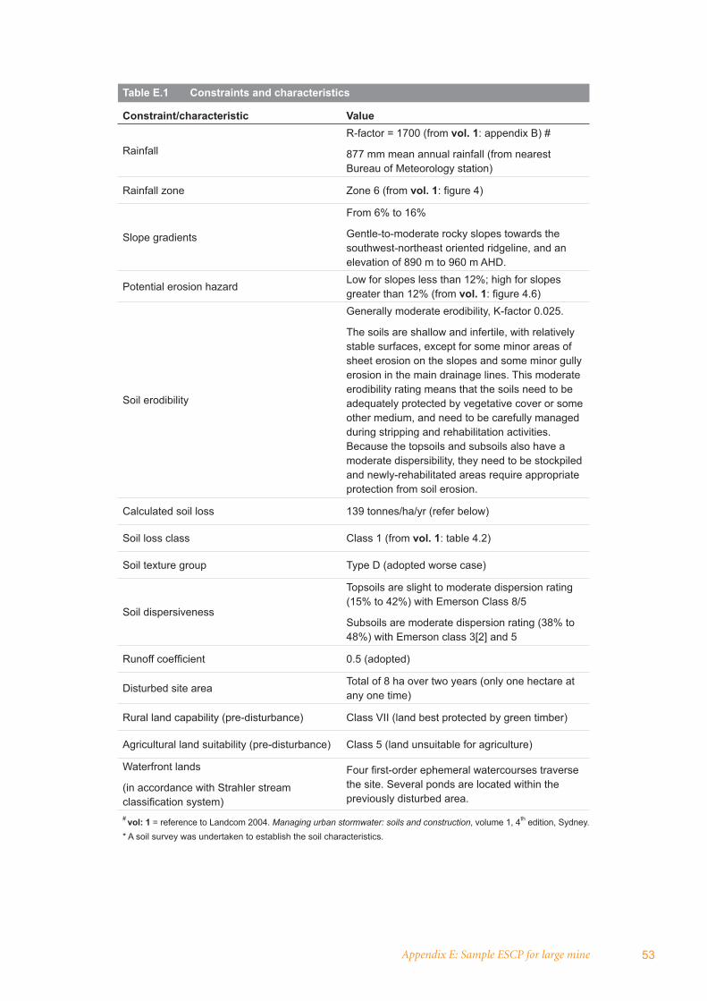
Appendix E: Sample ESCP for large mine 53
Table E.1 Constraints and characteristics
Constraint/characteristic Value
RainfallR-factor = 1700 (from vol. 1: appendix B) #
877 mm mean annual rainfall (from nearest Bureau of Meteorology station)
Rainfall zone Zone 6 (from vol. 1: fi gure 4)
Slope gradients
From 6% to 16%
Gentle-to-moderate rocky slopes towards the southwest-northeast oriented ridgeline, and an elevation of 890 m to 960 m AHD.
Potential erosion hazardLow for slopes less than 12%; high for slopes greater than 12% (from vol. 1: fi gure 4.6)
Soil erodibility
Generally moderate erodibility, K-factor 0.025.
The soils are shallow and infertile, with relatively stable surfaces, except for some minor areas of sheet erosion on the slopes and some minor gully erosion in the main drainage lines. This moderate erodibility rating means that the soils need to be adequately protected by vegetative cover or some other medium, and need to be carefully managed during stripping and rehabilitation activities. Because the topsoils and subsoils also have a moderate dispersibility, they need to be stockpiled and newly-rehabilitated areas require appropriate protection from soil erosion.
Calculated soil loss 139 tonnes/ha/yr (refer below)
Soil loss class Class 1 (from vol. 1: table 4.2)
Soil texture group Type D (adopted worse case)
Soil dispersiveness
Topsoils are slight to moderate dispersion rating (15% to 42%) with Emerson Class 8/5
Subsoils are moderate dispersion rating (38% to 48%) with Emerson class 3[2] and 5
Runoff coeffi cient 0.5 (adopted)
Disturbed site areaTotal of 8 ha over two years (only one hectare at any one time)
Rural land capability (pre-disturbance) Class VII (land best protected by green timber)
Agricultural land suitability (pre-disturbance) Class 5 (land unsuitable for agriculture)
Waterfront lands
(in accordance with Strahler stream classifi cation system)
Four fi rst-order ephemeral watercourses traverse the site. Several ponds are located within the previously disturbed area.
# vol: 1 = reference to Landcom 2004. Managing urban stormwater: soils and construction, volume 1, 4th edition, Sydney.* A soil survey was undertaken to establish the soil characteristics.

54 Managing urban stormwater: soils and construction – mines and quarries
Soil loss calculationSoil loss is calculated using the Revised Universal Soil Loss Equation (RUSLE) as detailed in appendix A of Managing urban stormwater: soils and construction, volume 1, 4th edition (Landcom 2004). This publication is referred to as vol. 1 throughout this ESCP.
The RUSLE values used are:
• R: 1700 (from table 1)
• K: 0.025 (from table 1)
• LS: 7.27 (2.14 to 8.78, assuming slope length of 150 m, and gradient of 6–16%
• P: 0.9 (from vol. 1: table A2 of appendix A)
• C: 0.5 (from vol. 1: fi gure A5 of appendix A)
Therefore, the soil loss (A) for the site follows:
A = R K LS P C
= 1700 x 0.025 x 7.27 x 0.9 x 0.5
= 139 tonnes/ha/yr
Surface hydrologyThe project site is within the upper extent of the Benellie River catchment, which is part of the larger Sarame River catchment. The site drains to two sub-catchments, which are shown as catchment C, and catchment H on fi gure E.3. The majority of the area of disturbance is within catchment H, which drains to Barracks Creek, whilst the area within catchment C drains to Commando Creek.
Within catchment C, there is one stream (hereafter referred to as stream 1) that fl ows though the proposed disturbance area. Stream 1 is an ephemeral (fi rst order) stream and has a small catchment (approximately 12 hectares) above the site. During previous mining activities the natural fl ow path of steam 1 was relocated within the mined area, and it currently fl ows within an artifi cial channel.
Within catchment H, there are three streams (hereafter referred to as streams 2, 3 and 4) that fl ow though the area of proposed rehabilitation and coal recovery activities. All three are ephemeral fi rst-order streams. Stream 2 has a very small catchment (approximately fi ve hectares) above the site. As a result of previous mining activities the natural fl ow path of stream 2 has been heavily modifi ed, with much of the surface fl ow being captured on the open-cut fl oor.
Stream 3 has a small catchment (approximately 24 hectares) above the site. It has been left largely undisturbed by previous mining activities and continues to fl ow along its natural alignment. However, there is signifi cant gully erosion within the stream, both upstream and downstream of the previously mined area.
Steam 4 has a very small catchment (approximately three hectares) above the site. This stream has been largely left undisturbed by previous mining activities and continues to fl ow along its natural alignment.
Previous mining activities resulted in spoil material (known as ‘out-of-pit’ spoil dumps) being placed in large, relatively continuous berms on the down-slope side of the disturbed area thereby containing most of the surface water entering the open-cut fl oor.
The catchment areas of streams 1 and 2 mainly fl ow into the existing open-cut fl oor. While the fl ows within steams 3 and 4 are generally allowed to fl ow though the previously
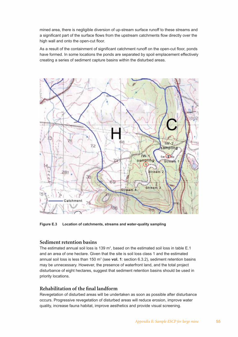
Appendix E: Sample ESCP for large mine 55
mined area, there is negligible diversion of up-stream surface runoff to these streams and a signifi cant part of the surface fl ows from the upstream catchments fl ow directly over the high wall and onto the open-cut fl oor.
As a result of the containment of signifi cant catchment runoff on the open-cut fl oor, ponds have formed. In some locations the ponds are separated by spoil emplacement effectively creating a series of sediment capture basins within the disturbed areas.
Sediment retention basinsThe estimated annual soil loss is 139 m3, based on the estimated soil loss in table E.1 and an area of one hectare. Given that the site is soil loss class 1 and the estimated annual soil loss is less than 150 m3 (see vol. 1: section 6.3.2), sediment retention basins may be unnecessary. However, the presence of waterfront land, and the total project disturbance of eight hectares, suggest that sediment retention basins should be used in priority locations.
Rehabilitation of the fi nal landformRevegetation of disturbed areas will be undertaken as soon as possible after disturbance occurs. Progressive revegetation of disturbed areas will reduce erosion, improve water quality, increase fauna habitat, improve aesthetics and provide visual screening.
Figure E.3 Location of catchments, streams and water-quality sampling
56 Managing urban stormwater: soils and construction – mines and quarries
E.4 Principal objectives of this ESCP The principle objectives of the ESCP are set out below.
• To minimise erosion and sedimentation from all active and rehabilitated areas, thereby minimising sediment ingress into surrounding surface waters.
• To ensure the segregation of ‘dirty’ water from ‘clean’ water, and maximise the retention time of ‘dirty’ water such that any discharge from the project site meets the relevant water-quality limits, including limits contained in relevant guidelines and any limits imposed by specifi c project approvals1. ‘Dirty’ water is defi ned as surface runoff from disturbed catchments (e.g. active areas of disturbance, run-of-mine (ROM), coal stockpiles, soil stockpiles and rehabilitated areas (until stabilised). ‘Clean’ water is defi ned as surface runoff from catchments that are undisturbed or relatively undisturbed by project-related activities and rehabilitated catchments.
• To minimise the volume of water discharged from the project site but, should the discharge of water prove necessary, ensure suffi cient settlement time is provided prior to discharge such that suspended sediment within the water meets the objectives identifi ed in the point above.
• To manage surface fl ows upstream of the project site so that rehabilitation and coal recovery activities are not affected by fl ooding.
• To minimise erosion of the ephemeral watercourses (streams 1 to 4) that traverse the site.
• To ensure sustainable long-term surface water features are established following rehabilitation of the site, including implementation of an effective revegetation and maintenance program.
• To monitor the effectiveness of surface water and sediment controls and to ensure all relevant surface-water quality criteria are met.
The principle design aspect of the project is the prevention of ‘clean’ water in ephemeral drainage channels entering the active disturbance area. This will be achieved through the use of cut-off drains, dams and piped diversions, as well as the containment of ‘dirty’ water in sediment control structures within the active areas of the project to eliminate any uncontrolled runoff. Each ephemeral watercourse will be restored, dams removed, and water re-directed into the natural channel once rehabilitation of the disturbed area is satisfactorily stable.
E.5 Erosion and sediment controls
General instructionsAll fi gures in this ESCP will be used in conjunction with the mining operations plan (MOP) and any other plans or written instructions that may be issued relating to the proposed development.
Contractors will ensure that all soil and water management works are undertaken as set out in this specifi cation and are constructed following the guidelines stated in vol. 1.
All subcontractors will be informed of their responsibilities in reducing the potential for soil erosion and pollution to down-slope areas.
1 pH: 6.5 to 7.5; electrical conductivity: 350 uS/cm; total suspended solids: 50 mg/L (from vol. 1). The values for pH and conductivity adopted for this sample ESCP are from ANZECC & ARMCANZ (2000), chapter 3 – aquatic ecosystems, and vary depending on whether the watercourse is an upland or lowland river.
Appendix E: Sample ESCP for large mine 57
Land disturbanceAll proposed erosion and sediment control measures will be implemented in advance of clearing and stripping operations, including the installation of sediment fencing down-slope of any areas that do not drain toward the ‘dirty’ water treatment areas. Sediment fencing will be installed in accordance with vol. 1: sediment fence SD 6-8.
Prior to clearing, the limits of disturbance will be marked by pegs placed at intervals on each side of the disturbed area. All operations will be planned to ensure that there is no damage to any trees outside the area being cleared.
Land disturbance will be minimised by clearing the smallest practical area of land ahead of rehabilitation and coal recovery activities and leaving this disturbed for the shortest possible time. This will be achieved by:
• restricting areas to be cleared of vegetation to the areas directly up-slope of the abandoned high wall
• programming the works so that only the areas suffi cient for the ensuing three to four months of operations will be cleared. While larger trees will initially be removed by a fi rewood contractor over the entire area to be disturbed, the remaining vegetation will only be cleared stage by stage, therefore limiting the time that areas are exposed and limiting the potential for erosion and sedimentation.
Topsoil managementTopsoil stripping within the disturbed area will, as far as practicable, be undertaken when the soil is in a slightly moist condition thus reducing damage to soil structure. The soil materials will not be stripped in wet conditions. The soils to be moved within the project site are generally highly structured, thus excessive handling of the materials, or handling when the soils are wet will be avoided to protect any structure that may have developed. Stripped soil will be transported to completed sections of the fi nal landform for immediate spreading if operational sequences, equipment scheduling and weather conditions permit. Where this is not the case, topsoil will be transferred to stockpiles within existing areas of disturbance, or at the perimeter of proposed activities to allow for immediate replacement once suitable areas of the fi nal landform are created.
If longer-term stockpiling (i.e. greater than three months) is required, a maximum stockpile height of two metres and a batter slope of 2:1 will be maintained to preserve biological viability and reduce soil deterioration.
Stockpiles will be placed in areas so as to avoid impediment of natural localised drainage lines and minimise the likelihood of water ponding against the stockpile. Stockpiles will be managed in accordance with vol. 1: stockpiles SD 4-1, including temporary erosion and sediment control measures such as earth banks and sediment fences.
Temporary clean water dams and diversion worksUp-slope water fl ows in streams 1, 2, 3 and 4 will be contained in dams and diverted through or around the disturbance area in pipes. The location of the clean water dams (CWDs) is shown on fi gure E.1, and a conceptual layout of the dam and diversionary works is shown in fi gure E.4, overleaf. Clean water fl owing in streams 1 to 4 will be prevented from entering the active disturbance area in the following sequence:
• Prior to ground disturbance commencing in a block through which a stream fl ows, clean water will be prevented from entering the active disturbance area by constructing a temporary dam immediately upstream of the block, and by constructing appropriately
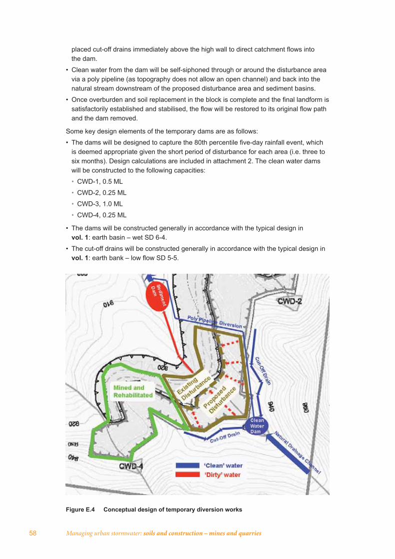
Managing urban stormwater: soils and construction – mines and quarries58
placed cut-off drains immediately above the high wall to direct catchment fl ows into the dam.
• Clean water from the dam will be self-siphoned through or around the disturbance area via a poly pipeline (as topography does not allow an open channel) and back into the natural stream downstream of the proposed disturbance area and sediment basins.
• Once overburden and soil replacement in the block is complete and the fi nal landform is satisfactorily established and stabilised, the fl ow will be restored to its original fl ow path and the dam removed.
Some key design elements of the temporary dams are as follows:
• The dams will be designed to capture the 80th percentile fi ve-day rainfall event, which is deemed appropriate given the short period of disturbance for each area (i.e. three to six months). Design calculations are included in attachment 2. The clean water dams will be constructed to the following capacities:
• CWD-1, 0.5 ML
• CWD-2, 0.25 ML
• CWD-3, 1.0 ML
• CWD-4, 0.25 ML
• The dams will be constructed generally in accordance with the typical design in vol. 1: earth basin – wet SD 6-4.
• The cut-off drains will be constructed generally in accordance with the typical design in vol. 1: earth bank – low fl ow SD 5-5.
Figure E.4 Conceptual design of temporary diversion works

Appendix E: Sample ESCP for large mine 59
A 100-mm (or larger) poly pipe will be used to self-siphon the dams through or around the disturbance area. This clean water will be discharged below the proposed sediment basins (sediment basin 1 or sediment basin 2). Using this method it is estimated that the release of design volumes will range from nine hours (CWD-4) to 94 hours (CWD-3). Water can be released more rapidly by the use of multiple pipes, or larger pipes. Design calculations for release times are included in attachment 2 to this ESCP.
A temporary energy dissipation device constructed of geotextile material, rock and/or sandbags will be used at the outlet of the poly pipe to prevent any scour of the natural stream from pipe discharge.
In-pit water management and sediment removalAll ‘dirty’ water will be contained within the disturbed area of the former and proposed open-cut fl oor and directed to internal erosion controls prior to discharge. The existing out-of-pit spoil dump will operate as a containment bund to ensure that there is no uncontrolled discharge from the active areas of the project.
The fl oor of the extraction area will be graded such that the ‘dirty’ water is directed to existing or constructed ponds within the existing open-cut fl oor. These ponds will act as sediment basins for the settlement of sediment prior to the discharge of water to the out-of-pit sediment basins. In some areas, the existing ponds will be lost as a result of the haul road construction. In these areas new internal controls will be implemented including, but not limited to, sediment fencing and sandbag sediment fi lters within internal drainage lines. Water accumulating in the ponds will be pumped or piped through the haul road to the out-of-pit sediment basins.
A sediment basin will also be constructed within the coal crushing area to capture any runoff from this area. This basin will be designed and constructed in accordance with the typical design in vol. 1: earth basin – wet SD 6-4.
Water from the internal sediment basins (ponds) will also be used for dust suppression purposes, which will assist in maintaining a water-capture capacity within the basins.
Out-of-pit sediment basinsTwo sediment basins will be constructed downstream of the operational areas in the locations shown in fi gure E.1. These will be designed and constructed to capture fl ows from the contributing catchments generally in accordance with the typical design in vol. 1:earth basin – wet SD 6-4.
The design capacity of both basins has been undertaken in accordance with the method recommended in Landcom (2004) for type D (dispersible) soils. The basins have been designed to capture the 80th percentile fi ve-day rainfall event, which is appropriate given the temporary nature of the disturbance (up to three years). Sediment basin 1 will have a capacity of approximately 1.8 ML, and sediment basin 2 a capacity of approximately 1.5 ML. Design calculations are included in attachment 1.
The basins have been located on the streams that will have the largest contributing disturbed catchment area. The remaining streams have signifi cantly smaller catchment areas and other controls will be implemented, including, but not necessarily limited to, sediment fencing and straw bale sediment fi lters. If necessary, ‘dirty’ water collected within the active or disturbed areas of the project will be pumped to the out-of-pit sediment basins.

Managing urban stormwater: soils and construction – mines and quarries60
The basins may need to be fl occulated to achieve settlement of the suspended particles due to the dispersible soils present. Where necessary, fl occulation will be carried out by using gypsum (or equivalent) in accordance with the manual dosing methodology contained in vol. 1: appendix E.
Haul road and site access roadThese roads will be constructed to ensure surface drainage is optimised and stabilised, thereby reducing roadside erosion and sedimentation. Cross-fall drainage structures and mitre drainage will be implemented for the entire length of the roads. Crowning will generally be implemented on any steeper sections of the roads. Outfall drainage will be constructed where the road traverses small fi ll batter areas, and in-fall drainage will occur where the road traverses larger fi ll batter areas. Road runoff will be intercepted at regular intervals to reduce runoff velocity in each mitre drain. Drain spacing will not exceed 50 metres.
Mitre drains will be constructed so that water from the internal haul road is directed to the in-pit sediment control structures or the out-of-pit sediment basins.
Rehabilitation of streamsOnce extraction works are completed, the land surface will be constructed in accordance with the proposed fi nal landform levels and progressively rehabilitated. At this time, any natural streams within the area will be reinstated to the original position of the stream. Once the surface of the stream and surrounding area is rehabilitated to a relatively stable condition, dams and diversion works will be removed and fl ows will be restored to the stream.
Streams will be restored with adequate controls to minimise the erosion within the restored section of creek, and controls to prevent the migration of any erosion upstream or downstream. Rock-lined channels will be constructed to form the channel surface. Key design elements of channel establishment works will include:
• the channel will be designed to convey the 100-ARI storm event, assuming that the catchment is partially vegetated
• the channels will be generally trapezoidal in shape with 3:1 (H:V) bank batters and a base width of two metres. The overall width of each channel will be at least four metres for stream 1; 3.5 metres for stream 2; 4.5 metres for stream 3; and three metres for stream 4.
• natural curves and meanders will be used instead of straight lines to refl ect natural stream characteristics
• the channel will be rock-lined rip rap constructed in accordance with vol. 1 and [this publication], including the placement of adequately sized rocks above a fi lter layer of suitable geotextile
• soil will be packed between rocks to allow sedges and grasses to be established within the channel for long-term channel stabilisation.
• works within the watercourse will be undertaken in accordance with vol. 1: section 5.3.3.
Following earthworks and channel establishment, a riparian corridor will be established with a minimum width of 20 metres, measured horizontally and at right angles to the fl ow from the top of both banks of the streams. As a result of the previous site operations, the existing watercourses are in a highly disturbed condition. Thus the rehabilitation program
Appendix E: Sample ESCP for large mine 61
will achieve long-term enhancement of the ecological value of the riparian corridor through the restoration of natural hydraulic conditions and the revegetation of appropriate vegetation.
Stream rehabilitation will be generally undertaken in accordance with the guideline Watercourse and riparian zone rehabilitation requirements, version 3 (DNR 2003). To comply with the guidelines, the keys aspects of the stream rehabilitation are:
• design and construction of the stream channel to provide for long-term stability
• implementation of effective temporary erosion controls to provide for the short-term stabilisation of the riparian corridor
• restoration of naturally occurring soil to the riparian corridor, i.e. as stripped from the area before disturbance
• restoration of the natural ecotone between riparian and terrestrial areas (20 metres from top of bank)
• establishment of a diverse range of locally occurring plant species
• establishment of a full range of vegetation types, including trees, shrubs and grass covers
• prohibition on introduction of exotic species
• maintenance of the rehabilitated riparian corridor for two years after initial rehabilitation.
Surface preparation for rehabilitation of fi nal landformThorough site preparation will be undertaken to ensure rapid establishment and growth of vegetation. Topsoil will be spread along the contour of regraded overburden to minimise erosion by dumping at the top of slopes and grading downwards and across the contour. Once the topsoil is spread, vehicle traffi c will be prevented from entering the area. If necessary, some areas will remain without topsoil after fi nal regrading, although these areas will then be sown to fulfi l the revegetation objectives.
Gypsum and/or lime may be applied to the fi nal surface using broadcasting machinery immediately prior to sowing. The ameliorants will be incorporated to a nominal depth of 300 mm.
Soil will be re-spread in the reverse sequence to its removal, so that the organic layer, containing any seed or vegetation, is returned to the surface. Topsoil will be spread to a minimum depth of 100 mm on 3:1 or steeper slopes and to a minimum depth of 50 mm on fl atter slopes. Re-spreading on the contour will aid runoff control and increase moisture retention for subsequent plant growth.
Re-spread topsoil will be levelled to achieve an even surface, while avoiding a compacted or an over-smooth fi nish.
After topsoil spreading, all topsoiled areas will be contour-ripped to an indicative depth of 400 to 500 mm to create a ‘key’ between the soil and replaced overburden. To minimise erosion, ripping will be undertaken on the contour. Contour banks will be constructed where ripping in the above manner is insuffi cient to prevent erosion. Rip lines and contour banks will be directed to the closest watercourse.
A sterile cover crop (oats and/or Japanese millet) may be applied to assist with initial soil stabilisation and used in different ratios according to the season, as shown in vol. 1: table 9.4.
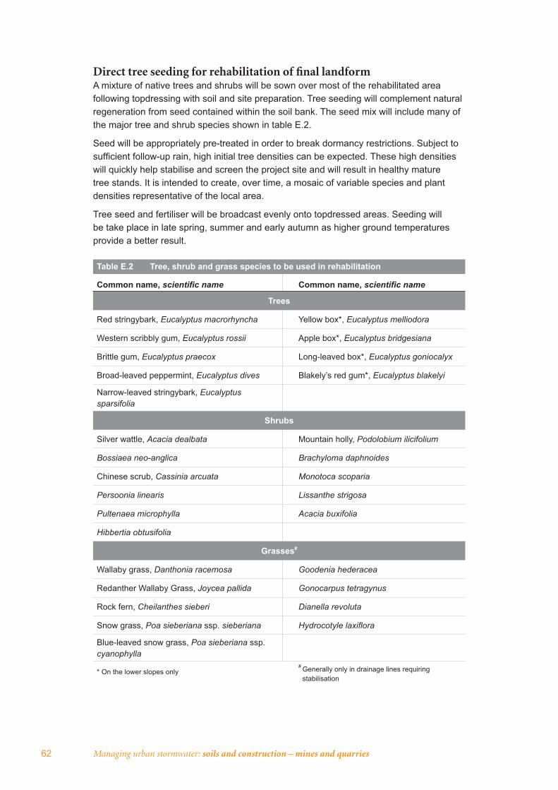
62 Managing urban stormwater: soils and construction – mines and quarries
Direct tree seeding for rehabilitation of fi nal landformA mixture of native trees and shrubs will be sown over most of the rehabilitated area following topdressing with soil and site preparation. Tree seeding will complement natural regeneration from seed contained within the soil bank. The seed mix will include many of the major tree and shrub species shown in table E.2.
Seed will be appropriately pre-treated in order to break dormancy restrictions. Subject to suffi cient follow-up rain, high initial tree densities can be expected. These high densities will quickly help stabilise and screen the project site and will result in healthy mature tree stands. It is intended to create, over time, a mosaic of variable species and plant densities representative of the local area.
Tree seed and fertiliser will be broadcast evenly onto topdressed areas. Seeding will be take place in late spring, summer and early autumn as higher ground temperatures provide a better result.
Table E.2 Tree, shrub and grass species to be used in rehabilitation
Common name, scientifi c name Common name, scientifi c name
Trees
Red stringybark, Eucalyptus macrorhyncha Yellow box*, Eucalyptus melliodora
Western scribbly gum, Eucalyptus rossii Apple box*, Eucalyptus bridgesiana
Brittle gum, Eucalyptus praecox Long-leaved box*, Eucalyptus goniocalyx
Broad-leaved peppermint, Eucalyptus dives Blakely’s red gum*, Eucalyptus blakelyi
Narrow-leaved stringybark, Eucalyptussparsifolia
Shrubs
Silver wattle, Acacia dealbata Mountain holly, Podolobium ilicifolium
Bossiaea neo-anglica Brachyloma daphnoides
Chinese scrub, Cassinia arcuata Monotoca scoparia
Persoonia linearis Lissanthe strigosa
Pultenaea microphylla Acacia buxifolia
Hibbertia obtusifolia
Grasses#
Wallaby grass, Danthonia racemosa Goodenia hederacea
Redanther Wallaby Grass, Joycea pallida Gonocarpus tetragynus
Rock fern, Cheilanthes sieberi Dianella revoluta
Snow grass, Poa sieberiana ssp. sieberiana Hydrocotyle laxifl ora
Blue-leaved snow grass, Poa sieberiana ssp.cyanophylla
* On the lower slopes only# Generally only in drainage lines requiring
stabilisation
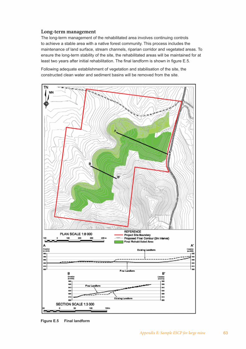
Appendix E: Sample ESCP for large mine 63
Long-term managementThe long-term management of the rehabilitated area involves continuing controls to achieve a stable area with a native forest community. This process includes the maintenance of land surface, stream channels, riparian corridor and vegetated areas. To ensure the long-term stability of the site, the rehabilitated areas will be maintained for at least two years after initial rehabilitation. The fi nal landform is shown in fi gure E.5.
Following adequate establishment of vegetation and stabilisation of the site, the constructed clean water and sediment basins will be removed from the site.
Figure E.5 Final landform
64 Managing urban stormwater: soils and construction – mines and quarries
MaintenanceThe site manager will undertake regular general environmental inspections to ensure that all the water management controls are functioning as designed and required. The site manager will also ensure that any contractors on site are operating within the environmental controls required for their activities. Site drainage and sediment control structures will be inspected regularly after runoff events (greater than 10 mm in 24 hours) to check for scouring of diversion drains and accumulation of materials in sediment traps, such as sediment fences and sandbags, and sediment basins.
Controls Where these are not functioning correctly, the surface will be restored to meet the required standard. Where signifi cant erosion is occurring regularly, additional controls will be constructed in general accordance with those presented in vol. 1.
Haul roads will be visually inspected to ensure that the appropriate mitigation measures are functioning to convey the surface fl ows from the road and work areas without causing erosion on the adjacent land. Where signifi cant erosion is occurring regularly, additional controls, such as mitre drains, scour protection of road drainage, and re-grading of the road surface, will be constructed.
Clean dams Regular visual checks will be made of the dams to ensure that there is no noticeable increased discoloration or undesirable sediment build-up, and that dams are in a stable condition. The pipeline will be inspected to ensure that there are no leaks or blockages to fl ow. Any signs of erosion at the points of discharge will be noted and remedial works undertaken as required. Where signifi cant erosion is observed, additional erosion controls will be constructed such as new rock scour protection at the discharge locations.
Sediment basins Regular visual checks will be made to ensure that there is no noticeable increased discoloration or undesirable sediment build-up in the basins, and that they remain in a stable condition. All sediment fencing and sandbag sediment fi lters will be inspected to ensure that they are functioning adequately.
Restored stream channels These will be inspected to ensure that they are continuing to convey the fl ows in accordance with design. Any signs of erosion along the length of the banks and at the points of discharge will be noted and remedial works undertaken as required. Where signifi cant erosion is observed, additional erosion controls will be constructed. This may include establishment of further vegetation cover, armouring of the channel surface and construction of new-rock scour protection at the entry and discharge locations. Inspection will continue for at least two years after the initial rehabilitation works.
As part of the statutory ‘diligence and care’ responsibilities, the site manager will keep a log book, making entries at least weekly, immediately before forecast rain, and after rainfall. Entries will include:
• the volume and intensity of any rainfall events
• the condition of any soil and water management work
• the condition of vegetation and any need to irrigate
• the need for dust prevention strategies
• any remedial works to be undertaken.
The book will be kept on-site and made available to any authorised person on request. It will be given to the project manager at the conclusion of the works.

Appendix E: Sample ESCP for large mine 65
MonitoringSurface water quality will be monitored quarterly, with samples taken from the existing sites coded IW-1 and IW-2 (see fi gure E.3 and also from the new clean water dams (CWD-1 to CWD-4) and sediment basins 1 and 2 (see fi gure E.4). Water samples will be analysed for key parameters, including:
• pH
• electrical conductivity
• suspended solids.
Opportunistic grab samples may also be taken periodically from streams during signifi cant rainfall events. These samples will be analysed for the same parameters as above.
ReportingFor each sampling event, water quality results will be compared against the assessment criteria and any other relevant criteria that may be defi ned in the development consent. Any exceedence of criteria will trigger an immediate investigation to determine the cause of the exceedence and preparation of a corrective action plan to re-establish appropriate controls as necessary.
The reporting of all monitoring and measurement data will be undertaken in accordance with the requirements of the development consent, including notifi cation of monitoring/investigation results to external organisations if required. All results will be reported in an annual environmental management report (AEMR).
The proponent will also report results to DECC as soon as practicable after any incident with actual or potential signifi cant off-site impacts on people or the biophysical environment.
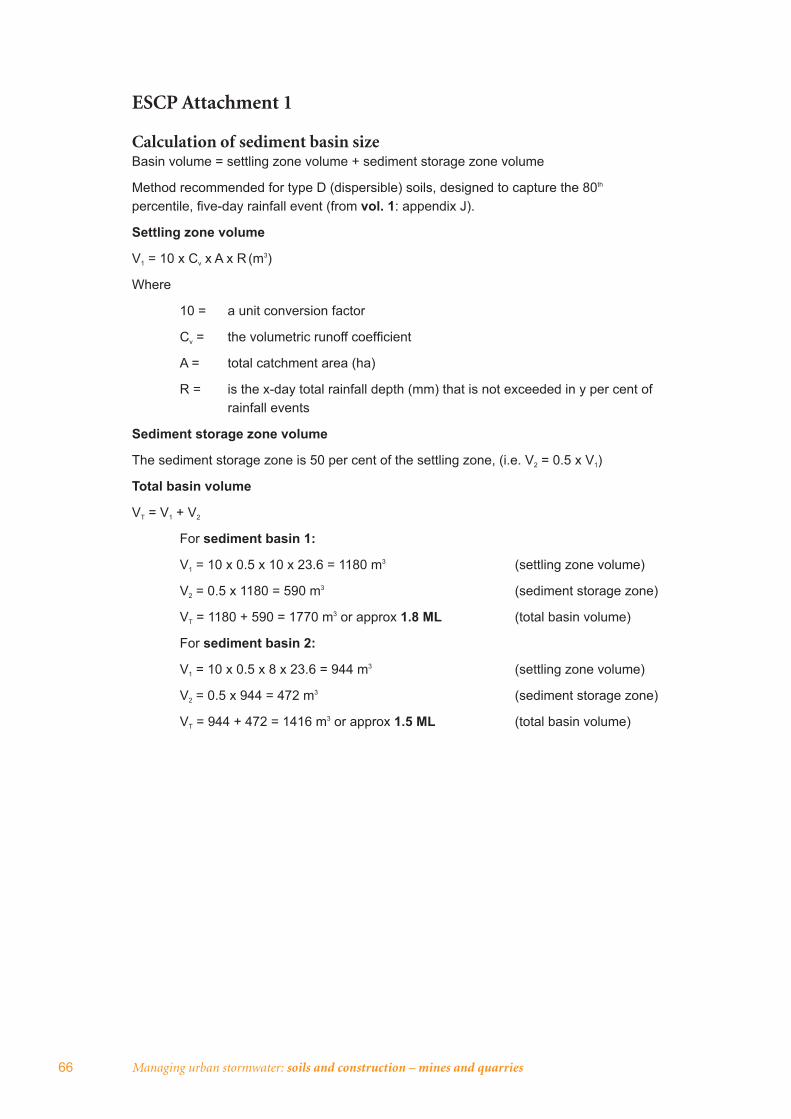
66 Managing urban stormwater: soils and construction – mines and quarries
ESCP Attachment 1
Calculation of sediment basin size Basin volume = settling zone volume + sediment storage zone volume
Method recommended for type D (dispersible) soils, designed to capture the 80th
percentile, fi ve-day rainfall event (from vol. 1: appendix J).
Settling zone volume
V1 = 10 x Cv x A x R (m3)
Where
10 = a unit conversion factor
Cv = the volumetric runoff coeffi cient
A = total catchment area (ha)
R = is the x-day total rainfall depth (mm) that is not exceeded in y per cent of rainfall events
Sediment storage zone volume
The sediment storage zone is 50 per cent of the settling zone, (i.e. V2 = 0.5 x V1)
Total basin volume
VT = V1 + V2
For sediment basin 1:
V1 = 10 x 0.5 x 10 x 23.6 = 1180 m3 (settling zone volume)
V2 = 0.5 x 1180 = 590 m3 (sediment storage zone)
VT = 1180 + 590 = 1770 m3 or approx 1.8 ML (total basin volume)
For sediment basin 2:
V1 = 10 x 0.5 x 8 x 23.6 = 944 m3 (settling zone volume)
V2 = 0.5 x 944 = 472 m3 (sediment storage zone)
VT = 944 + 472 = 1416 m3 or approx 1.5 ML (total basin volume)
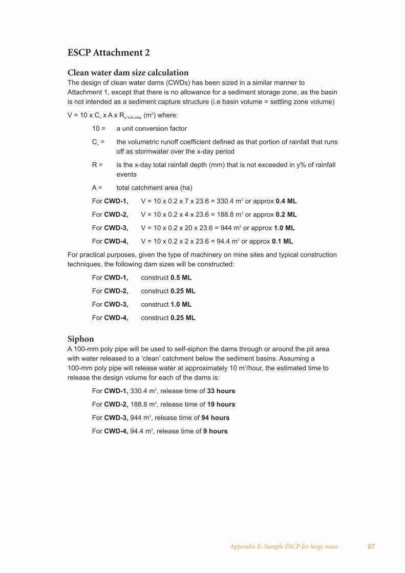
Appendix E: Sample ESCP for large mine 67
ESCP Attachment 2
Clean water dam size calculation The design of clean water dams (CWDs) has been sized in a similar manner to Attachment 1, except that there is no allowance for a sediment storage zone, as the basin is not intended as a sediment capture structure (i.e basin volume = settling zone volume)
V = 10 x Cv x A x Ry-%ile,xday (m3) where:
10 = a unit conversion factor
Cv = the volumetric runoff coeffi cient defi ned as that portion of rainfall that runs off as stormwater over the x-day period
R = is the x-day total rainfall depth (mm) that is not exceeded in y% of rainfall events
A = total catchment area (ha)
For CWD-1, V = 10 x 0.2 x 7 x 23.6 = 330.4 m3 or approx 0.4 ML
For CWD-2, V = 10 x 0.2 x 4 x 23.6 = 188.8 m3 or approx 0.2 ML
For CWD-3, V = 10 x 0.2 x 20 x 23.6 = 944 m3 or approx 1.0 ML
For CWD-4, V = 10 x 0.2 x 2 x 23.6 = 94.4 m3 or approx 0.1 ML
For practical purposes, given the type of machinery on mine sites and typical construction techniques, the following dam sizes will be constructed:
For CWD-1, construct 0.5 ML
For CWD-2, construct 0.25 ML
For CWD-3, construct 1.0 ML
For CWD-4, construct 0.25 ML
SiphonA 100-mm poly pipe will be used to self-siphon the dams through or around the pit area with water released to a ‘clean’ catchment below the sediment basins. Assuming a 100-mm poly pipe will release water at approximately 10 m3/hour, the estimated time to release the design volume for each of the dams is:
For CWD-1, 330.4 m3, release time of 33 hours
For CWD-2, 188.8 m3, release time of 19 hours
For CWD-3, 944 m3, release time of 94 hours
For CWD-4, 94.4 m3, release time of 9 hours

68 Managing urban stormwater: soils and construction – mines and quarries
ESCP Attachment 3
Standard drawingsThe following standard drawings from vol. 1 (Landcom 2004) are applicable to the recommended erosion and sediment controls:
• Stockpiles SD 4-1
• Earth basin – wet SD 6-4
• Earth bank – low fl ow SD 5-5
• Sediment fence SD 6-8.
[Note: The standard drawings referred to here would be included in a full copy of the ESCP.]
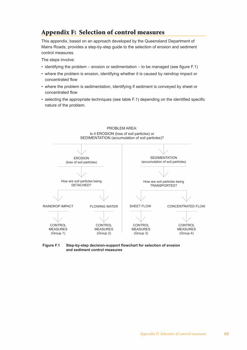
Appendix F: Selection of control measures 69
Appendix F: Selection of control measuresThis appendix, based on an approach developed by the Queensland Department of Mains Roads, provides a step-by-step guide to the selection of erosion and sediment control measures.
The steps involve:
• identifying the problem – erosion or sedimentation – to be managed (see fi gure F.1)
• where the problem is erosion, identifying whether it is caused by raindrop impact or concentrated fl ow
• where the problem is sedimentation, identifying if sediment is conveyed by sheet or concentrated fl ow
• selecting the appropriate techniques (see table F.1) depending on the identifi ed specifi c nature of the problem.
Figure F.1 Step-by-step decision-support flowchart for selection of erosion and sediment control measures
PROBLEM AREA:Is it EROSION (loss of soil particles) or
SEDIMENTATION (accumulation of soil particles)?
EROSION (loss of soil particles)
How are soil particles beingDETACHED?
RAINDROP IMPACT FLOWING WATER
CONTROL MEASURES
(Group 1)
CONTROL MEASURES
(Group 2)
CONTROL MEASURES
(Group 3)
CONTROL MEASURES
(Group 4)
SEDIMENTATION (accumulation of soil particles)
How are soil particles being TRANSPORTED?
SHEET FLOW CONCENTRATED FLOW
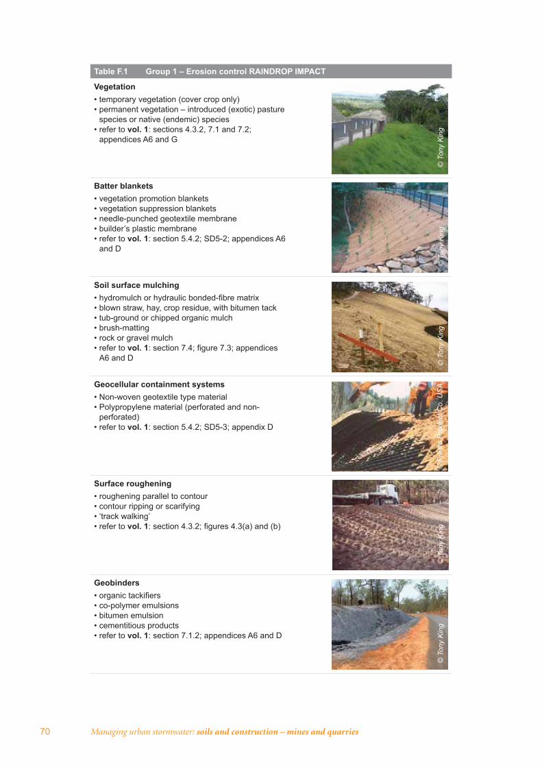
70 Managing urban stormwater: soils and construction – mines and quarries
Table F.1 Group 1 – Erosion control RAINDROP IMPACT
Vegetation • temporary vegetation (cover crop only)• permanent vegetation – introduced (exotic) pasture
species or native (endemic) species• refer to vol. 1: sections 4.3.2, 7.1 and 7.2;
appendices A6 and G
Batter blankets• vegetation promotion blankets• vegetation suppression blankets• needle-punched geotextile membrane• builder’s plastic membrane• refer to vol. 1: section 5.4.2; SD5-2; appendices A6
and D
Soil surface mulching• hydromulch or hydraulic bonded-fi bre matrix• blown straw, hay, crop residue, with bitumen tack• tub-ground or chipped organic mulch• brush-matting• rock or gravel mulch• refer to vol. 1: section 7.4; fi gure 7.3; appendices
A6 and D
Geocellular containment systems• Non-woven geotextile type material• Polypropylene material (perforated and non-
perforated)• refer to vol. 1: section 5.4.2; SD5-3; appendix D
Surface roughening• roughening parallel to contour• contour ripping or scarifying• ‘track walking’• refer to vol. 1: section 4.3.2; fi gures 4.3(a) and (b)
Geobinders• organic tackifi ers• co-polymer emulsions• bitumen emulsion• cementitious products• refer to vol. 1: section 7.1.2; appendices A6 and D
© T
ony
Kin
g©
Ton
y K
ing
© T
ony
Kin
g©
Pre
sto
Pro
duct
Co.
US
A©
Ton
y K
ing
© T
ony
Kin
g
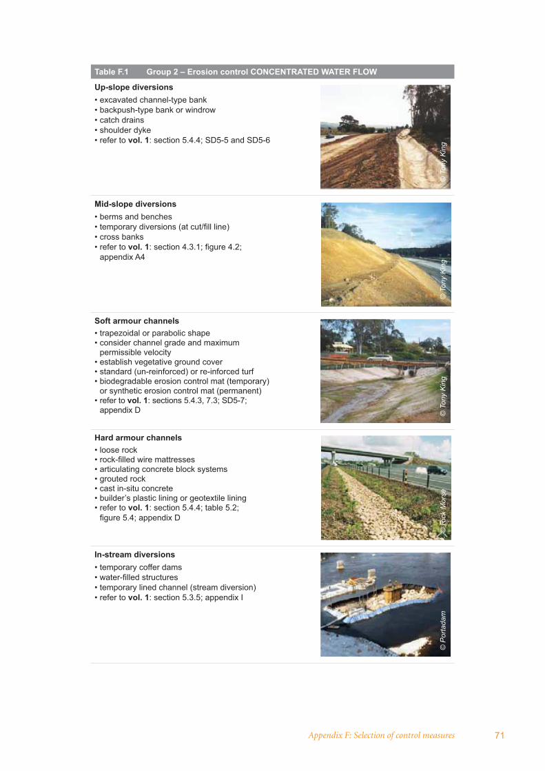
Appendix F: Selection of control measures 71
Table F.1 Group 2 – Erosion control CONCENTRATED WATER FLOW
Up-slope diversions • excavated channel-type bank• backpush-type bank or windrow• catch drains• shoulder dyke• refer to vol. 1: section 5.4.4; SD5-5 and SD5-6
Mid-slope diversions• berms and benches• temporary diversions (at cut/fi ll line)• cross banks• refer to vol. 1: section 4.3.1; fi gure 4.2;
appendix A4
Soft armour channels• trapezoidal or parabolic shape• consider channel grade and maximum
permissible velocity• establish vegetative ground cover• standard (un-reinforced) or re-inforced turf• biodegradable erosion control mat (temporary)
or synthetic erosion control mat (permanent)• refer to vol. 1: sections 5.4.3, 7.3; SD5-7;
appendix D
Hard armour channels• loose rock• rock-fi lled wire mattresses• articulating concrete block systems• grouted rock• cast in-situ concrete• builder’s plastic lining or geotextile lining• refer to vol. 1: section 5.4.4; table 5.2;
fi gure 5.4; appendix D
In-stream diversions• temporary coffer dams• water-fi lled structures • temporary lined channel (stream diversion)• refer to vol. 1: section 5.3.5; appendix I
© T
ony
Kin
g©
Ton
y K
ing
© T
ony
Kin
g©
Ric
k M
orse
©
Por
tada
m
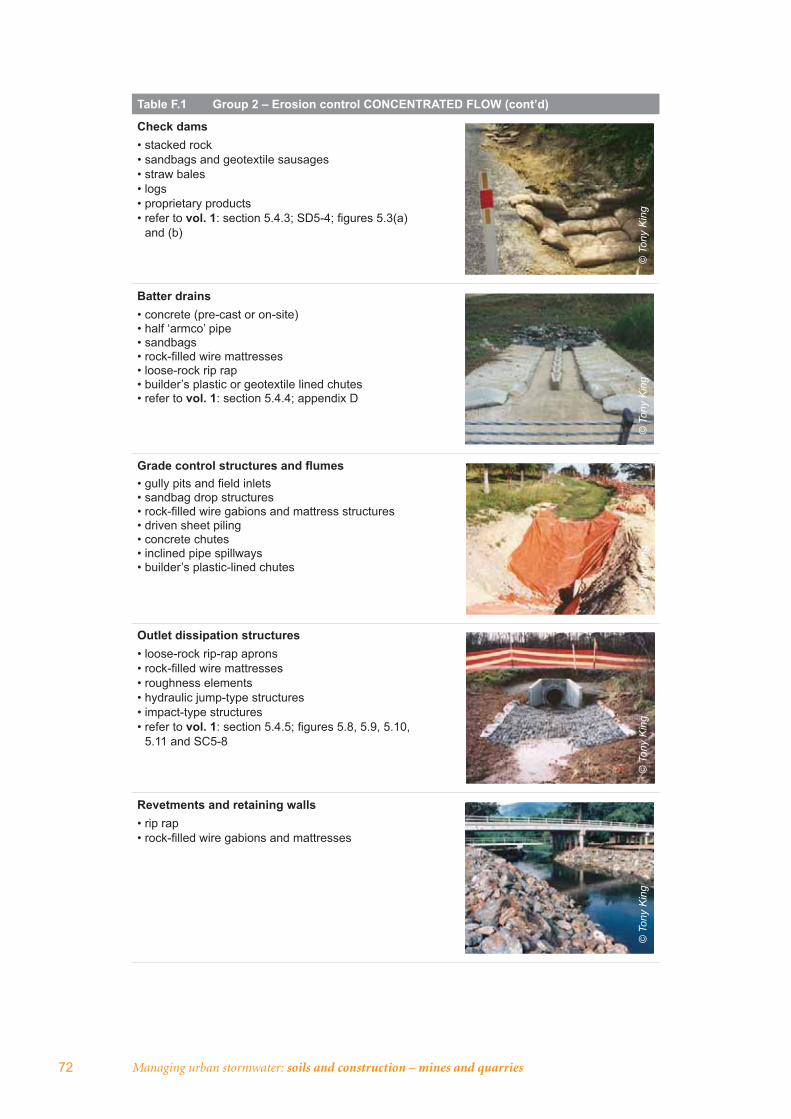
72 Managing urban stormwater: soils and construction – mines and quarries
Table F.1 Group 2 – Erosion control CONCENTRATED FLOW (cont’d)
Check dams• stacked rock• sandbags and geotextile sausages• straw bales• logs• proprietary products• refer to vol. 1: section 5.4.3; SD5-4; fi gures 5.3(a)
and (b)
Batter drains• concrete (pre-cast or on-site)• half ‘armco’ pipe• sandbags• rock-fi lled wire mattresses• loose-rock rip rap• builder’s plastic or geotextile lined chutes• refer to vol. 1: section 5.4.4; appendix D
Grade control structures and fl umes• gully pits and fi eld inlets• sandbag drop structures• rock-fi lled wire gabions and mattress structures• driven sheet piling• concrete chutes• inclined pipe spillways• builder’s plastic-lined chutes
Outlet dissipation structures• loose-rock rip-rap aprons• rock-fi lled wire mattresses• roughness elements• hydraulic jump-type structures• impact-type structures• refer to vol. 1: section 5.4.5; fi gures 5.8, 5.9, 5.10,
5.11 and SC5-8
Revetments and retaining walls• rip rap• rock-fi lled wire gabions and mattresses
© T
ony
Kin
g©
Ton
y K
ing
© T
ony
Kin
g©
Ton
y K
ing
© T
ony
Kin
g
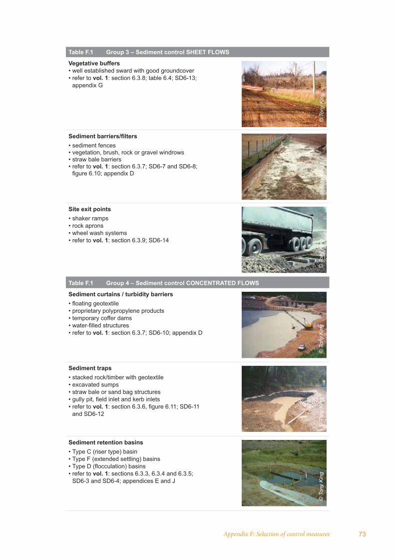
Appendix F: Selection of control measures 73
Table F.1 Group 3 – Sediment control SHEET FLOWS
Vegetative buffers• well established sward with good groundcover• refer to vol. 1: section 6.3.8; table 6.4; SD6-13;
appendix G
Sediment barriers/fi lters• sediment fences• vegetation, brush, rock or gravel windrows• straw bale barriers• refer to vol. 1: section 6.3.7; SD6-7 and SD6-8;
fi gure 6.10; appendix D
Site exit points• shaker ramps• rock aprons• wheel wash systems• refer to vol. 1: section 6.3.9; SD6-14
Table F.1 Group 4 – Sediment control CONCENTRATED FLOWS
Sediment curtains / turbidity barriers• fl oating geotextile• proprietary polypropylene products• temporary coffer dams• water-fi lled structures• refer to vol. 1: section 6.3.7; SD6-10; appendix D
Sediment traps • stacked rock/timber with geotextile• excavated sumps• straw bale or sand bag structures• gully pit, fi eld inlet and kerb inlets • refer to vol. 1: section 6.3.6, fi gure 6.11; SD6-11
and SD6-12
Sediment retention basins• Type C (riser type) basin• Type F (extended settling) basins• Type D (fl occulation) basins• refer to vol. 1: sections 6.3.3, 6.3.4 and 6.3.5;
SD6-3 and SD6-4; appendices E and J
© T
ony
Kin
g©
Ton
y K
ing
© T
ony
Kin
g©
Ton
y K
ing
© T
ony
Kin
g©
Ton
y K
ing

www.environment.nsw.gov.au


