VOLUME II STANDARD SPECIFICATIONS FOR WASTEWATER SYSTEM CONSTRUCTION For: BARROW COUNTY BOARD OF COMMISSIONERS 233 East Broad Street Winder, Georgia 30608 Phone (770) 307-3113 Fax (770) 307-3120 Prepared by: HSF Engineering, Inc. 2910 Brookside Run Snellville, Georgia 30078 Phone (770) 867-3545 Fax (770) 867-3567
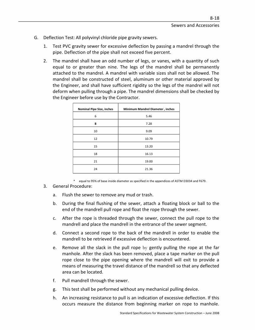
Transcript
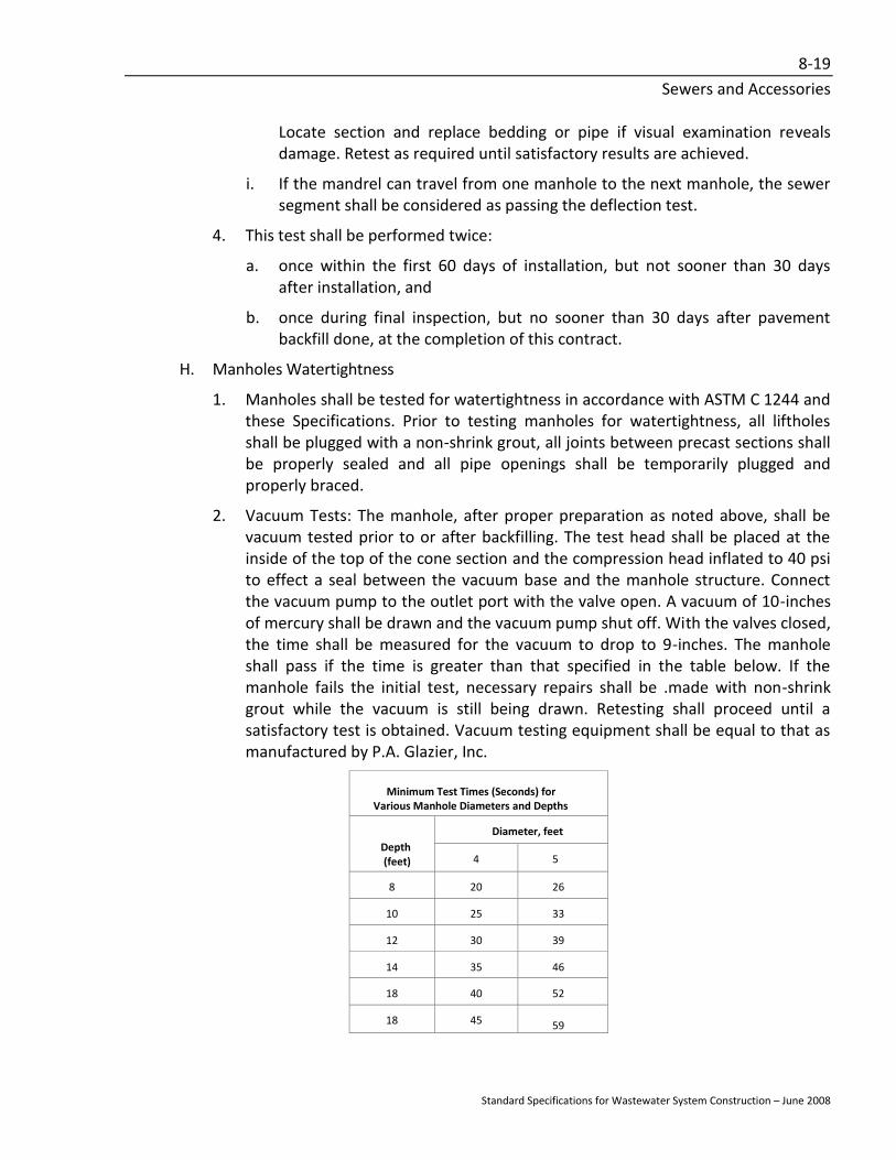
VOLUME II
STANDARD SPECIFICATIONS FOR
WASTEWATER SYSTEM CONSTRUCTION
For:
BARROW COUNTY BOARD OF COMMISSIONERS
233 East Broad Street Winder, Georgia 30608 Phone (770) 307-3113
Fax (770) 307-3120
Prepared by:
HSF Engineering, Inc. 2910 Brookside Run
Snellville, Georgia 30078 Phone (770) 867-3545
Fax (770) 867-3567
Standard Specifications for Wastewater System Construction – June 2008
PREFACE
The Standard Specifications have been prepared to complement and include by reference the Standard Detail Drawings and to provide the qualitative requirements for products, materials and workmanship for construction of additions to and replacements of the wastewater collection and transfer system which is to be operated by, or to be assured by a trust indenture with, the Board of Commissioners, Barrow County, Georgia. These Standard Specifications are only to be used for projects with Drawings which have been approved by the Georgia Environmental Protection Division, as prepared by the County's design consultant, or by a developer's engineer, whose Drawings must first be approved by Barrow County. All references in these Standard Specifications to "Engineer" and "Owner" shall mean the legal and authorized representative of the Board of Commissioners, Barrow County, Georgia. All references to "Project" shall mean the work being constructed under the jurisdiction of these Standard Specifications. All references to "Contractor" shall mean the individual, company or corporation constructing work under the jurisdiction of these Standard Specifications. All references to "Drawings" shall include, by reference, the Standard Detail Drawings accompanying these Standard Specifications. These Standard Specifications are subject to revision for a specific project, with such revisions noted on the Drawings approved by Barrow County.
Standard Specifications for Wastewater System Construction – June 2008
TABLE OF CONTENTS STANDARD SPECIFICATIONS
SECTION 1 SAFETY IN WASTEWATER WORKS ................................................................... 1-1
PART 1 GENERAL ............................................................................................................................1-1
SS-9 Concrete Pier PS-6 Chain Link Fence Elevation
SS-10 Concrete Pier PS-7 Bollard
SS-11 Pipe Anchorage PS-8 Backflow Preventer
STANDARD FORMS: Pipeline Testing Form
Standard Specifications for Wastewater System Construction – June 2008
SECTION 1 SAFETY IN WASTEWATER WORKS
PART 1 GENERAL
1.01 SCOPE
A. The Contractor shall be responsible for conducting all Work in a safe manner and shall take reasonable precautions to ensure the safety and protection of workers, property and the general public.
B. All construction shall be conducted in accordance with the latest applicable requirements for Part 1926 of the Occupational Safety and Health Act, Safety and Health Regulations for Construction, Section-107 of the Contract Work Hours and Safety Standards Act, as well as any other local, state or federal safety codes and regulations.
C. The Contractor shall designate a trained and qualified employee who is to be responsible for ensuring that the Work is performed safely and in conformance with all applicable regulations.
D. The Contractor shall determine the safety hazards involved in prosecuting the Work and the precautions necessary to conduct the Work safely.
E. The Contractor shall bear all risks associated with performing the Work and shall fully indemnify and hold harmless the Owner and Engineer.
1.02 SPECIAL REQUIREMENTS
A. The Contractor's attention is directed to the fact that construction activities involving sanitary sewer systems will occasionally involve work in potentially hazardous environments in which oxygen deficient, toxic or explosive conditions may exist. Additional hazards arise from the presence of pathogens in the wastewater and from the slime and scum layer that coat walking, working and-other surfaces. In dealing with these hazards, the Contractor shall take special precautions to ensure worker safety. Such precautions shall include, but are not limited to, the following, as applicable:
1. Installing temporary forced air ventilation equipment and ducts for fresh air in enclosed areas.
2. Using pneumatic tools and equipment instead of electric-driven equipment in hazardous areas.
3. Avoiding the use of cutting torches, field welding and grinders in hazardous areas.
4. Cleaning and disinfecting working surfaces with hot water, high, pressure washers prior to commencing work.
1-2
Safety in Wastewater Works
Standard Specifications for Wastewater System Construction – June 2008
5. Installing sealed wooden baffles or bulkheads to isolate working areas from hazardous atmospheres.
6. Providing portable oxygen meters, combustible gas detectors and hydrogen sulfide detectors to continuously monitor the atmosphere in enclosed working areas.
7. Providing safety harnesses, safety lines and recovery crews for workers in hazardous areas.
8. Providing self-contained breathing apparatus with spare air cylinders for workers in hazardous areas.
9. Providing dry chemical fire extinguishers and connected fire hoses in areas where a danger of fire or explosion exists.
10. Providing adequate, oxygen-equipped, first aid facilities.
11. Providing suitable wash-up areas and facilities for workers.
12. Installing temporary lighting using explosion-proof fixtures in hazardous environments.
13. Installing approved warning and hazard signs and posting safety procedures.
14. Instructing all workers as to the hazards present, the procedures to be followed and the proper function and use of all safety and emergency equipment furnished.
B. Prior to commencing Work on existing facilities and equipment, the Contractor shall notify the County and shall ensure that the source of electrical energy to all affected equipment is shut off and locked out at the appropriate motor control center. Local switches and pushbutton stations, where provided, shall be locked in the "off" position.
C. Prior to entering or commencing work in a hazardous area, the Contractor shall ensure that all safety and emergency equipment is in place and in satisfactory operating condition.
END OF SECTION
Standard Specifications for Wastewater System Construction – June 2008
SECTION 2 CLEARING AND GRUBBING
PART 1 GENERAL
1.01 SCOPE
A. Clearing and grubbing includes, but is not limited to, removing from the Project site, trees, stumps, roots, brush, structures, abandoned utilities, trash, debris and all other materials found on or near the surface of the ground in the construction area and understood by generally accepted engineering practice not to be suitable for construction of the type contemplated. Precautionary measures that prevent damage to existing features to remain is part of the Work.
B. Clearing and grubbing operations shall be coordinated with temporary and permanent erosion and sedimentation control procedures.
1.02 QUALITY ASSURANCE
A. The Contractor shall comply with applicable codes, ordinances, rules, regulations and laws of local, municipal, state or federal authorities having jurisdiction over the Project. All required permits of a temporary nature shall be obtained for construction operations by the Contractor.
B. Open burning, if allowed, shall first be permitted by the local authority having jurisdiction. The Contractor shall notify the local fire department and abide by fire department restrictions.
1.03 JOB CONDITIONS
Location of the Work: The area to be cleared and grubbed is shown schematically on the Drawings or specified below. It includes all areas designated for construction.
1.04 PROJECT ACCESS
Where private property is used for access to the Project site, the Contractor shall obtain written permission for such access from the affected private property owners. The Contractor shall be solely responsible for all damage caused by access through the private property.
PART 2 PRODUCTS
2.01 EQUIPMENT
The Contractor shall furnish equipment of the type normally used in clearing and grubbing operations including, but not limited to, tractors, trucks and loaders.
2-2
Clearing and Grubbing
Standard Specifications for Wastewater System Construction – June 2008
PART 3 EXECUTION
3.01 SCHEDULING OF CLEARING
A. The Contractor shall clear at each construction site only that length of the right-of-way, permanent or construction easement which would be the equivalent of one month's pipe laying.
B. The Engineer may permit clearing for additional lengths of the pipe line provided that temporary erosion and sedimentation controls are in place and a satisfactory stand of temporary grass is established. Should a satisfactory stand of grass not be possible, no additional clearing shall be permitted beyond that specified above.
C. A satisfactory stand of grass shall have no bare spots larger than one square yard. Bare spots shall be scattered and the bare area shall not comprise more than one percent of any given area.
3.02 CLEARING AND GRUBBING
A. Clear and grub as required on each side of the pipeline before excavating. Remove all trees, growth, debris, stumps and other objectionable matter. Clear the construction easement or road right-of-way only if necessary.
B. Grubbing shall consist of completely removing roots, stumps, trash and other debris from all graded areas so that topsoil is free of roots and debris. Topsoil is to be left sufficiently clean so that further picking and raking will not be required.
C. All stumps, roots, foundations and planking embedded in the ground shall be removed and disposed of. Piling and butts of utility poles shall be removed to a minimum depth of two feet below the limits of excavation for structures, trenches and roadways or two feet below finish grade, whichever is lower.
D. Landscaping features shall include, but are not necessarily limited to, fences, cultivated trees, cultivated shrubbery, property corners, man-made improvements, subdivision and other signs within the right-of-way and easement. The Contractor shall take extreme care in moving landscape features and promptly re-establishing these features.
E. Surface rocks and boulders shall be grubbed from the soil and removed from the site if not suitable as rip rap.
F. Where the tree limbs interfere with utility wires, or where the trees to be felled are in close proximity to utility wires, the tree shall be taken down in sections to eliminate the possibility of damage to the utility.
G. Any work pertaining to utility poles shall comply with the requirements of the appropriate utility.
H. All fences adjoining any excavation or embankment that, in the Contractor's opinion, may be damaged or buried, shall be carefully removed, stored and replaced. Any fencing that, in the Engineer's opinion, is significantly damaged shall be replaced with new fence material.
2-3
Clearing and Grubbing
Standard Specifications for Wastewater System Construction – June 2008
I. The Contractor shall exercise special precautions for the protection and preservation of trees, cultivated shrubs, sod, fences, etc. situated within the limits of the construction area but not directly within excavation and/or fill limits. The Contractor shall be held liable for any damage the Contractor's operations have inflicted on such property.
J. The Contractor shall be responsible for all damages to existing improvements resulting from Contractor's operations.
3.03 DISPOSAL OF DEBRIS
A. The debris resulting from the clearing and grubbing operation shall be hauled to a disposal site secured by the Contractor and shall be disposed of in accordance with all requirements of federal, state, county and municipal regulations. No debris of any kind shall be deposited in any stream or body of water, or in any street or alley. No debris shall be deposited upon any private property except with written consent of the property owner. A copy of written consent shall be provided to the Owner for permanent records. In no case shall any material or debris be left on the Project, shoved onto abutting private properties or buried on the Project.
B. When approved in writing by the Owner and when authorized by the proper authorities, the Contractor may dispose of such debris by burning on the Project site provided all requirements set forth by the governing authorities are met. The authorization to burn shall not relieve the Contractor in any way from damages which may result from Contractor's operations. On easements through private property, the Contractor shall not burn on the site unless written permission is also secured from the property owner, in addition to authorization from the proper authorities.
END OF SECTION
Standard Specifications for Wastewater System Construction – June 2008
SECTION 3 EROSION AND SEDIMENTATION CONTROL
PART 1 GENERAL
1.01 SCOPE
A. All erosion and sedimentation control measures must be designed and conducted using Best Management Practices (BMP) in accordance with the Georgia Erosion and Sedimentation Act of 1975 (GESA), as amended, the Manual for Erosion and Sedimentation Control in Georgia, latest edition, Section 402 of the Federal Clean Water Act and applicable codes, ordinances, rules, regulations and laws of local and municipal authorities having jurisdiction.
B. It is the Owner/Developer’s responsibility to ensure compliance with GESA and conform to any and all NPDES guidelines and requirements.
C. Temporary erosion controls and Best Management Practices, include, but are not limited to, grassing, mulching, watering and reseeding on-site surfaces and spoil and borrow area surfaces, and providing interceptor ditches at ends of berms and at those locations which will ensure that erosion during construction will be either eliminated or maintained within acceptable limits as established by the Georgia Erosion and Sedimentation Act of 1975 (GESA) and all subsequent amendments (O.C.G.A. § 12-7-1 et seq.), Section 402 of the Federal Clean Water Act,
D. Temporary sedimentation controls include, but are not limited to, silt dams, traps, barriers, filter stone and appurtenances at the foot of sloped surfaces which will ensure that sedimentation pollution will be either eliminated or maintained within acceptable limits as established by the Federal Clean Water Act of 1987, as amended.
E. Land disturbance activity shall not commence until all erosion and sedimentation control measures have been installed and the Land Disturbance Permit has been issued.
F. Basic Principles
1. Conduct the earthwork and excavation activities in such a manner to fit the topography, soil type and condition.
2. Minimize the disturbed area and the duration of exposure to erosion elements.
3. Stabilize disturbed areas immediately.
4. Safely convey run-off from the site to an outlet such that erosion will not be increased off site.
5. Retain sediment on site that was generated on site.
6. Minimize encroachment upon watercourses.
7. All erosion and sedimentation control measures shall be designed for a minimum 25 year storm event.
3-2
Erosion and Sedimentation Control
Standard Specifications for Wastewater System Construction – June 2008
8. Construct erosion and sedimentation control devices prior to clearing and excavation activities.
G. Temporary Erosion and Sedimentation Control: In general, temporary erosion and sedimentation control procedures shall be directed toward:
1. Preventing soil erosion at the source.
2. Preventing silt and sediment from entering any waterway if soil erosion cannot be prevented.
3. Preventing silt and sediment from migrating downstream in the event it cannot be prevented from entering the waterway.
H. Permanent Erosion Control: Permanent erosion control measures shall be implemented to prevent sedimentation of the waterways and to prevent erosion of the Project site.
END OF SECTION
Standard Specifications for Wastewater System Construction – June 2008
SECTION 4 TRENCH EXCAVATION AND BACKFILL
PART 1 GENERAL
1.01 SCOPE
A. The work under this Section consists of furnishing all labor, equipment and materials and performing all operations in connection with the trench excavation and backfill required to install the pipelines shown on the Drawings and as specified.
B. Excavation shall include the removal of any trees, stumps, brush, debris or other obstacles which remain after the clearing and grubbing operations, which may obstruct the work, and the excavation and removal of all earth, rock or other materials to the extent necessary to install the pipe and appurtenances in conformance with the lines and grades shown on the Drawings and as specified.
C. Backfill shall include the refilling and compaction of the fill in the trenches and excavations up to the surrounding ground surface or road grade at crossing.
D. The trench is divided into five specific areas:
1. Foundation: The area beneath the bedding, sometimes also referenced to as trench stabilization.
2. Bedding: The area above the trench bottom (or foundation) and below the bottom of the barrel of the pipe.
3. Haunching: The area above the bottom of the barrel of the pipe up to a specified height above the bottom of the barrel of the pipe.
4. Initial Backfill: The area above the haunching material and below a plane 12 inches above the top of the barrel of the pipe or the top of duct bank.
5. Final Backfill: The area above a plane 12 inches above the top of the barrel of the pipe.
E. The choice of method, means, techniques and equipment rests with the Contractor. The Contractor shall select the method and equipment for trench excavation and backfill depending upon the type of material to be excavated and backfilled, the depth of excavation, the amount of space available for operation of equipment, storage of excavated material proximity of man-made improvements to be protected, available easement or right-of-way and prevailing practice in the area.
1.02 QUALITY ASSURANCE
A. Density: All references to "maximum dry density" shall mean the maximum dry density defined by ASTM D 698, except that for cohesionless, free draining soils "maximum dry density" shall mean the maximum index density as determined by ASTM D 4253. Determination of the density of foundation, bedding, haunching, or backfill materials in place shall meet with the requirements of ASTM D 1556, ASTM D 2922 or ASTM D 2937.
4-2
Trench Excavation and Backfill
Standard Specifications for Wastewater System Construction – June 2008
B. Sources and Evaluation Testing: Testing of materials to certify conformance with the Specifications shall be performed by an independent testing laboratory. All imported fill materials shall meet the requirements of on-site fill materials.
1.03 SAFETY
Perform all trench excavation and backfilling activities in accordance with the Occupational Safety and Health Act of 1970 (PL 91-596), as amended. The Contractor shall pay particular attention to the Safety and Health Regulations Part 1926, Subpart P "'Excavation, Trenching & Shoring" as described in OSHA publication 2226. Particular attention is drawn to the requirement that the Contractor must have on site and individual with current competent person training certification.
PART 2 PRODUCTS
2.01 TRENCH FOUNDATION MATERIALS
Crushed stone shall be utilized for trench foundation (trench stabilization) and shall meet the requirements of the Georgia Department of Transportation Specification 800.01, Group I (limestone, marble or dolomite) or Group II (quartzite, granite or gneiss). Stone sizes shall be between No. 57 and No. 4, inclusive.
2.02 BEDDING AND HAUNCHING MATERIALS
A. Unless shown on the Drawings or specified otherwise, bedding and haunhing materials shall be as follows:
1. Gravity Sewers: Crushed stone as specified above.
2. Gravity Sewer Services: Earth materials as specified below, except under pavement.
3. Force Mains: Earth materials as specified below, except under pavement.
B. Under Pavement: Bedding and haunching material under all pavement areas or where the trench is within three feet of the pavement edge shall be crushed stone as specified above.
C. Earth materials utilized for bedding and haunching shall be suitable materials selected from materials excavated from the trench. Suitable materials shall be clean and free of rock larger than 2 inches at its largest dimension, organics, cinders, stumps, limbs, frozen earth or mud, man-made wastes and other unsuitable materials. Should the material excavated from the trench be saturated, the saturated material may be used as earth material, provided it is allowed to dry properly and it is capable of meeting the specified compaction requirements. When necessary, earth bedding and haunching materials shall be moistened to facilitate compaction by tamping. If materials excavated from the trench are not suitable for use as bedding or haunching material, provide select material conforming to the requirements of this Section.
4-3
Trench Excavation and Backfill
Standard Specifications for Wastewater System Construction – June 2008
2.03 INITIAL BACKFILL
A. Unless shown on the Drawings or specified otherwise, initial backfill material shall be crushed stone or earth materials as specified for bedding and haunching materials.
B. Earth materials utilized for initial backfill shall be suitable materials selected from materials excavated from the trench. Suitable materials shall be clean and free of rock larger than 2 inches at its largest dimension, organics, cinders, stumps, limbs, frozen earth or mud, man-made wastes and other unsuitable materials. Should the material excavated from the trench be saturated, the saturated material may be used as earth material, provided it is allowed to dry properly and it is capable of meeting the specified compaction requirements. When necessary, initial backfill materials shall be moistened to facilitate compaction by tamping. If materials excavated from the trench are not suitable for use as initial backfill material, provide select material conforming to the requirements of this Section.
2.04 FINAL BACKFILL
Unless shown on the Drawings or specified otherwise, final backfill material shall be general excavated earth materials, shall not contain more than one/third broken rock, of which no stone or boulder shall weigh more than 50 pounds, cinders, stumps, limbs, man-made wastes and other unsuitable materials. If materials excavated from the trench are not suitable for use as final backfill material, provide select material conforming to the requirements of this Section.
2.05 SELECT BACKFILL
Select backfill shall be materials which meet the requirements as specified for bedding, haunching, initial backfill or final backfill materials, including compaction requirements.
2.06 CONCRETE
Concrete for bedding, haunching, initial backfill or encasement shall have a compressive strength of not less than 3,000 psi, with not less than 5.5 bags of cement per-cubic yard and a slump between 3 and 5 inches. Ready-mixed concrete shall be mixed and transported in accordance with ASTM C 94. Reinforcing steel shall conform to the requirements of ASTM A 615, Grade 60.
2.07 FLOWABLE FILL
Flowable fill, where required for trench backfill, shall meet the requirements of Georgia Department of Transportation Standard Specifications, Section 600 for Excavatable or Non-Excavatable type.
2.08 GRANULAR MATERIAL
Granular material, where required for trench backfill, shall be sand, river sand, crushed stone or aggregate, pond screenings, crusher run, recycled concrete, or other angular material. Granular material shall meet gradation requirements for Size No. 57 or finer.
4-4
Trench Excavation and Backfill
Standard Specifications for Wastewater System Construction – June 2008
PART 3 EXECUTION
3.01 TRENCH EXCAVATION
A. Topsoil and grass shall be stripped a minimum of 6 inches over the trench excavation site and stockpiled separately for replacement over the non-paved, finished grading areas.
B. Trenches shall be excavated to the lines and grades shown on the Drawings with the centerlines of the trenches on the centerlines of the pipes and to the dimensions which provide the proper support and protection of the pipe and other structures and accessories.
C. Trench Width for Pipelines
1. The sides of all trenches shall be as vertical as is practical to a minimum of one foot above the top of the pipe. Unless otherwise indicated on the Drawings, the maximum trench width shall be equal to the sum of the outside diameter of the pipe plus two feet. The minimum trench width shall be that which allows the proper consolidation of the haunching and initial backfill material.
2. Excavate the top portion of the trench to any width within the construction easement or right-of-way which will not cause unnecessary damage to adjoining structures, roadways, pavement, utilities, trees or private property. Where necessary to accomplish this, provide sheeting and shoring.
3. Where rock is encountered in trenches, excavate to remove boulders and stones to provide a minimum of 6 inches clearance between the rock and any part of the pipe or manhole.
4. Wherever the prescribed maximum trench width is exceeded, the Contractor shall use the next higher Class or Type of bedding and haunching as shown on the Drawings for the full trench width as actually cut. The excessive trench width may be due to unstable trench walls, inadequate or improperly placed bracing and sheeting which caused sloughing, accidental over-excavation, intentional over-excavation necessitated by the size of the Contractor's tamping and compaction equipment, intentional over-excavation due to the size of the Contractor's excavation equipment, or other reasons beyond the control of the Engineer or Owner.
D. Depth
1. The trenches shall be excavated to the required depth or elevation which allow for the placement of the pipe and bedding to the dimensions shown on the Drawings or specified.
2. Force Mains
a. Excavate trenches to provide a minimum cover of 36 inches. Within the right-of-way of highways, streets or roadways, also excavate to place the top
4-5
Trench Excavation and Backfill
Standard Specifications for Wastewater System Construction – June 2008
of the pipe a minimum of 36 inches below the nearest pavement edge or drainage ditch.
b. Increase the depth of cover where specifically shown on the Drawings and where necessary to avoid interference with underground utilities and obstructions.
3. Where rock is encountered in trenches for pipelines, excavate to the minimum depth which will provide clearance below the pipe barrel of 8 inches for pipe 21 inches in diameter and smaller and 12 inches for larger pipe, valves and manholes. Remove boulders and stones to provide a minimum of 6-inches clearance between the rock and any part of the pipe, manhole or accessory.
E. Excavated Material
1. Excavated materials shall be placed adjacent to the work to be used for Backfilling as required. Top soil shall be carefully separated and lastly placed in its original location.
2. Excavated material shall be placed sufficiently back from the edge of the excavation to prevent caving of the trench wall, to permit safe access along the trench and not cause any drainage problems. Excavated material shall be placed so as not to damage existing landscape features or man-made improvements.
F. Sewer trench excavation shall not extend more than 400 feet beyond pipe installation.
3.02 SHEETING, BRACING AND SHORING
A. Sheeting, bracing and shoring shall be performed in the following instances:
1. Where sloping of the trench walls does not adequately protect persons within the trench from slides or cave-ins.
2. In caving ground.
3. In wet, saturated, flowing or otherwise unstable materials. The sides of all trenches and excavations shall be adequately sheeted, braced and shored.
4. Where necessary to prevent damage to adjoining buildings, structures, roadways, pavement, utilities, trees or private properties which are required to remain.
5. Where necessary to maintain the top of the trench within the available construction easement or right-of-way.
B. In all cases, excavation protection shall strictly conform to the requirements of the Occupational Safety and Health Act of 1970, as amended. The County shall direct where density tests will be performed along the Project route.
C. Timber: Timber for shoring, sheeting, or bracing shall be sound and free of large or loose knots and in good, serviceable condition. Size and spacing shall be in accordance with OSHA regulations.
4-6
Trench Excavation and Backfill
Standard Specifications for Wastewater System Construction – June 2008
D. Steel Sheeting and Sheet Piling: Steel sheet piling shall be the continuous interlock type. The weight, depth and section modulus of the sheet piling shall be sufficient to restrain the loads of earth pressure and surcharge from existing foundations and live loads. Procedure for installation and bracing shall be so scheduled and coordinated with the removal of the earth that the ground under existing structures shall be protected against lateral movement at all times. The Contractor shall provide closure and sealing between sheet piling and existing facilities.
E. Trench Shield: A trench shield or box may be used to support the trench walls. The use of a trench shield does not necessarily preclude the additional use of bracing and sheeting. When trench shields are used, care must be taken to avoid disturbing the alignment and grade of the pipe or disrupting the haunching of the pipe as the shield is moved. When the bottom of the trench shield extends below the top of the pipe, the trench shield will be raised in 6-inch increments with specified backfilling occurring simultaneously. At no time shall the trench shield be "dragged" with the bottom of the shield extending below the top of the pipe or utility.
F. Remove bracing and sheeting in units when backfill reaches the point necessary to protect the pipe and adjacent property. Leave sheeting in place when in the opinion of the Engineer it cannot be safely removed or is within three feet of an existing structure, utility, or pipeline. Cut off any sheeting left in place at least two feet below the surface.
G. Sheet piling within three feet of an existing structure or pipeline shall remain in place, unless otherwise directed by the Engineer.
3.03 ROCK EXCAVATION
A. Definition of Rock: Any material which cannot be excavated with conventional excavating equipment, and is removed by drilling and blasting, and occupies an original volume of at least one-half cubic yard.
B. Blasting: Provide licensed, experienced workmen to perform blasting. Conduct blasting operations in accordance with all existing ordinances and regulations. Protect all buildings and structures from the effects of the blast. Repair any resulting damage. If the Contractor repeatedly uses excessive blasting charges or blasts in an unsafe or improper manner, the Engineer may direct the Contractor to employ an independent blasting consultant to supervise the preparation for each blast and approve the quantity of each charge.
C. Removal of Rock: Dispose of rock off site that is surplus or not suitable for use as rip rap or backfill.
D. The Contractor shall notify the Engineer prior to any blasting. Additionally, the Contractor shall notify the Engineer and local fire department before any charge is set.
E. The Contractor shall conduct pre-blast and post-blast inspections of structures, including photographs or videos, and maintain a detailed written log.
F. Where blasting is to be performed on Georgia Department of Transportation right-of-
4-7
Trench Excavation and Backfill
Standard Specifications for Wastewater System Construction – June 2008
way, the Contractor shall be responsible for providing the Owner sufficient information to obtain a blasting permit from the Georgia DOT in a timely manner.
3.04 DEWATERING EXCAVATIONS
A. Dewater excavation continuously to maintain a water level two feet below the bottom of the trench.
B. Control drainage in the vicinity of excavation so the ground surface is properly pitched to prevent water running into the excavation.
C. There shall be sufficient pumping equipment, in good working order, available at all times, to remove any water that accumulates in excavations. Where the utility crosses natural drainage channels, the work shall be conducted in such a manner that unnecessary damage or delays in the prosecution of the work will be prevented. Provision shall be made for the satisfactory disposal of surface water to prevent damage to public or private property.
D. In all cases, accumulated water in the trench shall be removed before placing bedding or haunching, laying pipe, placing concrete or backfilling.
E. Where dewatering is performed by pumping the water from a sump, crushed stone shall be used as the medium for conducting the water to the sump. Sump depth shall be at least two feet below the bottom of the trench, Pumping equipment shall be of sufficient quantity and/or capacity to maintain the water level in the sump two feet below the bottom of the trench. Pumps shall be a type such that intermittent flows can be discharged. A standby pump shall be required in the event the operating pump or pumps clog or otherwise stop operation.
F. Dewater by use of a well point system when pumping from sumps does not lower the water level two feet below the trench bottom. Where soil conditions dictate, the Contractor shall construct well points cased in sand wicks. The casing, 6 to 10-inches in diameter, shall be jetted into the ground, followed by the installation of the well point, filling casing with sand and withdrawing the casing.
3.05 TRENCH FOUNDATION AND STABILIZATION
A. The bottom of the trench shall provide a foundation to support the pipe and its specified bedding. The trench bottom shall be graded to support the pipe and bedding uniformly throughout its length and width.
B. If, after dewatering as specified above, the trench bottom is spongy, or if the trench bottom does not provide firm, stable footing and the material at the bottom of the trench will still not adequately support the pipe, the trench will be determined to be unsuitable and the Engineer shall then authorize placement of trench stabilization.
C. Should the undisturbed material encountered at the trench bottom constitute, in the opinion of the Engineer, an unstable foundation for the pipe, the Contractor shall be required to remove such unstable material and fill the trench to the proper subgrade with crushed stone as directed by the Engineer.
4-8
Trench Excavation and Backfill
Standard Specifications for Wastewater System Construction – June 2008
D. Where trench stabilization is provided, the trench stabilization material shall be compacted to at least 90 percent of the maximum dry density, unless shown or specified otherwise.
3.06 BEDDING AND HAUNCHING
A. Prior to placement of bedding material, the trench bottom shall be free of any water, loose rocks, boulders or large dirt clods.
B. Bedding material shall be placed to provide uniform support along the bottom of the pipe and to place and maintain the pipe at the proper elevation. The initial layer of bedding placed to receive the pipe shall be brought to the grade and dimensions indicated on the Drawings. All bedding shall extend the full width of the trench bottom. The pipe shall be placed and brought to grade by tamping the bedding material or by removal of the excess amount of the bedding material under the pipe. Adjustment to grade line shall be made by scraping away or filling with bedding material. Wedging or blocking up of pipe shall not be permitted. Applying pressure to the top of the pipe, such as with a backhoe bucket, to lower the pipe to the proper elevation or grade shall not be permitted. Each pipe section shall have a uniform bearing on the bedding for the length of the pipe, except immediately at the joint.
C. At each joint, excavate bell holes of ample depth and width to permit the joint to be assembled properly and to relieve the pipe bell of any load.
D. After the pipe section is properly placed, add the haunching material to the specified depth. The haunching material shall be shovel sliced, tamped, vigorously chinked or otherwise consolidated to provide uniform support for the pipe barrel and to fill completely the voids under the pipe, including the bell hole. Prior to placement of the haunching material, the bedding shall be clean and free of any water, loose rocks, boulders or dirt clods.
E. Gravity Sewers
1. PVC Pipe: Excavate the bottom of the trench flat at a minimum depth as shown on the Drawings, below the bottom of the pipe barrel. Place and compact bedding material to the proper grade. Haunching material shall then be carefully placed by hand and compacted to provide full support under and up to the top of the pipe.
2. Ductile Iron Pipe: Excavate the bottom of the trench flat at a minimum depth as shown on the Drawings, below the bottom of the pipe barrel. Place and compact bedding material to the proper grade. Haunching material shall then be carefully placed by hand and compacted to provide full support under and up to a height of one-fourth the outside diameter of the pipe above the bottom of the pipe barrel
F. Manholes: Excavate to a minimum of 12 inches below the planned elevation of the base of the manhole. Place and compact crushed stone bedding to the required grade before constructing the manhole.
4-9
Trench Excavation and Backfill
Standard Specifications for Wastewater System Construction – June 2008
G. Ductile Iron Pipe Force Mains
1. Unless otherwise shown on the Drawings or specified, utilize earth materials for bedding and haunching.
2. Unless specified or shown otherwise, bedding shall meet the requirements for Type 2 Pipe Bedding. Unless specified or shown otherwise for restrained joint pipe and fittings, bedding shall meet the requirements for Type 3 Pipe Bedding_
H. Excessive Width and Depth
1. Gravity Sewers: If the trench is excavated to excess width, fill the trench with crushed stone to 6-inches above the top of the pipe.
2. Pressure Mains: If the trench is excavated to excess width, fill the trench with crushed stone to the quarter point on the pipe.
3. If the trench is excavated to excessive depth, provide crushed stone to place the bedding at the proper elevation or grade.
I. Compaction: Bedding and haunching materials under pipe, manholes and accessories shall be compacted to a minimum of 90 percent of the maximum dry density, unless shown or specified otherwise.
3.07 INITIAL BACKFILL
A. Initial backfill shall be placed to anchor the pipe, protect the pipe from damage by subsequent backfill and ensure the uniform distribution of the loads over the top of the pipe.
B. Place initial backfill material carefully around the pipe in uniform layers to a depth of at least 12 inches above the pipe barrel. Layer depths shall be a maximum of 6 inches.
C. Backfill on both sides of the pipe simultaneously to prevent side pressures.
D. Compact each layer thoroughly with suitable hand tools or tamping equipment.
E. Initial backfill shall be compacted to a minimum 90 percent of the maximum dry density, unless shown or specified otherwise.
F. If materials excavated from the trench are not suitable for use as backfill materials, provide select backfill material conforming to the requirements of this Section.
3.08 CONCRETE ENCASEMENT FOR PIPELINES
Where concrete encasement is shown on the Drawings for pipelines, excavate the trench to provide a minimum of 12-inches clearance from the barrel of the pipe. Lay the pipe to line and grade on concrete blocks. In lieu of bedding, haunching and initial backfill, place concrete to the full width of the trench and to a height of not less than 12 inches above the pipe barrel. Do not backfill the trench for a period of at least 24 hours after concrete is placed.
4-10
Trench Excavation and Backfill
Standard Specifications for Wastewater System Construction – June 2008
3.09 FINAL BACKFILL
A. Backfill carefully to restore the ground surface to its original condition.
B. Except under pavement areas, the top 6 inches shall be topsoil obtained as specified in "Trench Excavation" of this Section.
C. Excavated material which is unsuitable for backfilling, and excess material, shall be disposed of in a manner approved by the Engineer and in a manner that will not adversely impact the environment. Surplus soil may be neatly distributed and spread over the site, if approved by the Engineer. If such spreading is allowed, the site shall be left in a clean and sightly condition and shall not affect pre-construction drainage patterns. Surplus rock from the trenching operations shall be removed from the site.
D. If materials excavated from the trench are not suitable for use as backfill materials, provide select backfill material conforming to the requirements of this Section.
E. After initial backfill material has been placed and compacted, backfill with final backfill material. Place backfill material in uniform layers, compacting each layer thoroughly as follows:
1. In 6 inch layers, if using light power tamping equipment, such as a "jumping jack"
2. In 12 inch layers, if using heavy tamping equipment, such as hammer with tamping feet
3. In 24 inch layers, if using a hydra-hammer
F. Settlement: If trench settles, re-fill and grade the surface to conform to the adjacent surfaces.
G. Final backfill shall be compacted to a minimum 90 percent of the maximum dry density, unless specified otherwise.
3.10 ADDITIONAL MATERIAL
Where final grades above the pre-construction grades are required to maintain minimum cover, additional fill material will be as shown on the.. Drawings. Utilize excess material excavated from the trench, if the material is suitable. - If excess excavated materials are not suitable, or if the quantity available is not sufficient, provide additional suitable fill material.
3.11 BACKFILL UNDER ROADS
Compact backfill underlying pavement and sidewalks, and backfill under dirt and gravel roads to a minimum 95 percent of the maximum dry density. The top 12 inches shall be compacted to a minimum of 98 percent of the maximum dry density.
3.12 BACKFILL WITHIN GEORGIA DOT RIGHT-OF-WAY
Backfill within the Georgia DOT right-of-way shall meet the requirements stipulated in the "Utility Accommodation Policy and Standards", published by the Georgia Department of Transportation.
4-11
Trench Excavation and Backfill
Standard Specifications for Wastewater System Construction – June 2008
3.13 BACKFILL ALONG RESTRAINED JOINT PIPE
Backfill along restrained joint pipe shall be compacted to a minimum 90 percent of the maximum dry density.
3.14 FLOWABLE FILL
A. Where flowable fill is required, excavate the trench to provide a minimum of 6-inches clearance on either side of the pipe barrel. Lay the pipe to line and grade onsolid concrete blocks or bricks. In lieu of bedding, haunching and initial backfill, place flowable fill to the full width and depth of the trench.
B. Flowable fill shall be protected from freezing for a period of 36 hours after placement. Minimum temperature of flowable fill at point of delivery shall be 50 degrees F.
C. The Contractor shall provide steel plates over flowable fill in road locations.
3.15 COMPACTED GRANULAR MATERIAL
Where compacted granular material is required as initial and final backfill material, it shall be placed after bedding and haunching material specified elsewhere has been placed. Compacted granular material shall be compacted to a minimum 95 percent of the maximum dry density.
3.16 TESTING AND INSPECTION
A. All costs associated with compaction testing ordered by the County shall be paid for by the Contractor.
B. Frequency: The extent of testing required shall be reasonable, but shall also be dependent upon soil conditions, Contractor's means and methods of operation, and regulatory requirements. As a minimum, compaction tests shall be performed in two foot lifts at a single location between each manhole per each existing or proposed public right-of-way. The County will direct where density tests will be performed along the Project route.
C. The soils testing laboratory is responsible for the following:
1. Compaction tests in accordance with Article 1.02 of this Section.
2. Inspecting and testing stripped site, subgrades and proposed fill materials.
D. The Contractor's duties relative to testing include:
1. Notifying laboratory of conditions requiring testing.
2. Coordinating with laboratory for field testing.
3. Paying costs for testing, including testing performed beyond the scope of that required, and for re-testing where initial tests reveal non-conformance with specified requirements.
4. Providing excavation as necessary for laboratory personnel to conduct tests.
4-12
Trench Excavation and Backfill
Standard Specifications for Wastewater System Construction – June 2008
E. Inspection
1. Earthwork operations, acceptability of excavated materials for bedding or backfill, and placing and compaction of bedding and backfill is subject to inspection by the Engineer.
2. Where required by the Engineer, foundations and shallow spread footing foundations are required to be inspected by a geotechnical engineer, who shall verify suitable bearing and construction.
F. Comply with applicable codes, ordinances, rules, regulations and laws of local, municipal, state or federal authorities having jurisdiction.
END OF SECTION
Standard Specifications for Wastewater System Construction – June 2008
SECTION 5 BORE AND JACK CASINGS
PART 1 GENERAL
1.01 SCOPE
A. The work covered by this Section includes furnishing all labor, materials and equipment required to bore and jack casings and to properly complete pipeline construction as described herein and/or shown on the Drawings.
B. Supply all materials and perform all work in accordance with applicable American Society for Testing and Materials (ASTM), American Water Works Association (AWWA), American National Standards Institute (ANSI) or other recognized standards. Latest revisions of all standards are applicable. If requested by the Engineer, submit evidence that manufacturer has consistently produced products of satisfactory quality and performance over a period of at least two years.
1.02 SUBMITTALS
A. If required by the County or Engineer, submit shop drawings, product data and experience.
B. Material Submittals: If required by the County or Engineer, the Contractor shall provide shop drawings and other pertinent specifications and product data as follows:
1. Shop drawings for casing pipe showing sizes and connection details.
2. Design mixes for concrete and grout.
3. Casing Spacers.
C. Experience Submittals: Boring and jacking casings is deemed to be specialty contractor work. A minimum of five continuous years of experience in bore and jack casing construction is required of the casing installer. Evidence of this experience must be provided for review by the Engineer.
1.03 STORAGE AND PROTECTION
All materials shall be stored and protected in accordance with the manufacturer's recommendations and as approved by the Engineer.
PART 2 PRODUCTS
2.01 MATERIALS AND CONSTRUCTION
A. Casing
1. The casing shall be new and unused pipe. The casing shall be made from steel plate having a minimum yield strength of 35,000 psi. The steel plate shall also meet the chemical requirements of ASTM A 36.
5-2
Bore and Jack Casings
Standard Specifications for Wastewater System Construction – June 2008
2. The thicknesses of casing shown in paragraph B. below are minimum thicknesses. Actual thicknesses shall be determined by the casing installer, based on its evaluation of the required forces to be exerted on the casing when jacking. Any buckling of the casing due to jacking forces shall be repaired.
3. The diameters of casing shown in paragraph B. below and shown on the Drawings are minimum. Larger casings, with the Engineer's approval, may be provided for whatever reasons the Contractor may decide, whether casing size availability, line and grade tolerances, soil conditions, etc.
B. Casing Sizes
UNDER HIGHWAYS
Pipe Diameter, inches
Casing Diameter, inches
Wall Thickness, inches
6 12 0.250
8 16 0.250
10 16 0.250
12 18 0.250
14 22 0.250
16 24 0.250
18 26 0.312
C. Casing Spacers: Casing spacers shall meet one of the following requirements:
1. Casing spacers shall be flanged, bolt-on style with a two-section stainless steel shell lined with a PVC liner, minimum 0.09-inch thick also having a hardness of 85-90 durometer. Runners shall be attached to stainless steel risers which shall be properly welded to the shell. The height of the runners and risers shall be manufactured such that the pipe does not float within the casing. Casing spacers shall be Cascade Waterworks Manufacturing Company or Advanced Products & Systems, Inc.
2. Casing spacers shall be a two-section, flanged, bolt on style constructed of heat fused PVC coated steel, minimum 14 gauge band and 10 gauge risers, with 2-inch wide glass reinforced polyester insulating skids, heavy duty PVC inner liner, minimum 0.09-inch thick having a hardness of 85-90 durometer, and all stainless steel or cadmium plated hardware shall be Pipeline Seal and Insulator, Inc.
D. Grout: Grout may be used for filling the void between the casing pipe and the carrier pipe: Cement shall conform to ASTM C 150, Type I or Type II. Grout shall have a minimum compressive strength of 100 psi attained within 24 hours.
E. Carrier Pipe: Carrier pipes shall meet requirements as specified in Section 8 or Section 9 of these Specifications.
5-3
Bore and Jack Casings
Standard Specifications for Wastewater System Construction – June 2008
F. Surface Settlement Markers: Surface settlement markers within pavement areas shall be nails. Surface settlement markers within non-paved areas shall be wooden hubs.
2.02 EQUIPMENT
A. A cutting head shall be attached to a continuous auger mounted inside the casing pipe.
B. On casing pipe for gravity sewer over 60 feet in length, the installation equipment shall include a steering head and a grade indicator.
C. The steering head shall be controlled manually from the bore pit. The grade indicator shall consist of a water level attached to the casing which would indicate the elevation of the front end of the casing or some other means for grade indication approved by the Engineer.
PART 3 EXECUTION
3.01 GENERAL
A. Interpretation of soil investigation reports and data, investigating the site and determination of the site soil conditions prior to bidding is the sole responsibility of the Contractor. Any subsurface investigation by the Contractor must be approved by the appropriate authority having jurisdiction over the site.
B. Casing construction shall be performed so as not to interfere with, interrupt or endanger roadway surface and activity thereon, and minimize subsidence of the surface, structures, and utilities above and in the vicinity of the casing. Support the ground continuously in a manner that will prevent loss of ground and keep the perimeters and face of the casing, passages and shafts stable. The Contractor shall be responsible for all settlement resulting from casing operations and shall repair and restore damaged property to its original or better condition.
C. Face Protection: The face of the excavation shall be protected from the collapse of the soil into the casing.
D. Casing Design: Design of the bore pit and required bearing to resist jacking forces are the responsibility of the Contractor. The excavation method selected shall be compatible with expected ground conditions. The lengths of the casing shown on the Drawings are the minimum lengths required. The length of the casing may be extended for the convenience of the Contractor, at no additional cost to the County. Due to restrictive right-of-way and construction easements, casing lengths less than the nominal 20 foot length may be necessary.
E. Highway Crossings
1. The Contractor shall be held responsible and accountable for the coordinating and scheduling of all construction work within the highway right-of-way.
2. Work along or across the highway department rights-of-way shall be subject to inspection by such highway department.
5-4
Bore and Jack Casings
Standard Specifications for Wastewater System Construction – June 2008
3. All installations shall be performed to leave free flows in drainage ditches, pipes, culverts or other surface drainage facilities of the highway, street or its connections.
4. No excavated material or equipment shall be placed on the pavement or shoulders of the roadway without the express approval of the highway department.
5. In no instance will the Contractor be permitted to leave equipment (trucks, backhoes, etc.) on the pavement or shoulder overnight. Construction materials to be installed, which are placed on the right-of-way in advance of construction, shall be placed in such a manner as not to interfere with the safe operation of the roadway.
6. Where blasting is to be performed on Georgia Department of Transportation right-of-way, the Contractor shall be responsible for providing the County sufficient information to obtain a blasting permit from the Georgia DOT in a timely manner.
F. Railroad Crossings
1. The Contractor shall secure permission from the Railroad to schedule work so as not to interfere with the operation of the Railroad.
2. Additional insurance is required for each railroad crossing. The Contractor shall furnish the Railroad with such additional insurance as may be needed. Cost of the same shall be borne by the Contractor.
3. All work on the Railroad right-of-way, including necessary support of tracks, safety of operations and other standard and 'incidental operation procedures may be under the supervision of the appropriate authorized representative of the Railroad affected and any decisions of this representative pertaining to construction and/or operations shall be final and construction must be governed by such decisions.
4. If, in the opinion of the Railroad, it becomes necessary to provide flagging protection, watchmen or the performance of any other work in order to keep the tracks safe for traffic, the Contractor shall coordinate such work and shall reimburse the Railroad, in cash, for such services, in accordance with accounting procedures agreed on by the Contractor and affected Railroad before construction is started.
5. No blasting shall be permitted within the Railroad right-of-way
3.02 GROUNDWATER CONTROL
A. The Contractor shall control the groundwater throughout the construction of the casing.
B. Methods of dewatering shall be at the option and responsibility of the Contractor. Maintain close observation to detect settlement or displacement of surface facilities
5-5
Bore and Jack Casings
Standard Specifications for Wastewater System Construction – June 2008
due to dewatering. Should settlement or displacement be detected, notify the Engineer immediately and take such action as necessary to maintain safe conditions and prevent damage.
C. When water is encountered, provide and maintain a dewatering system of sufficient capacity to remove water on a 24 hour basis keeping excavations free of water until the backfill operation is in progress. Dewatering shall be performed in such a manner that removal of soil particles is held to minimum. Dewater into a sediment trap and comply with requirements specified in Section 3 of these Specifications.
3.03 SAFETY
A. Provide all necessary bracing, bulkheads and shields to ensure complete safety to all traffic, persons and property at all times during the work. Perform the work in such a manner as to not permanently damage the roadbed or interfere with normal traffic over it.
B. Observe all applicable requirements of the regulations of the authorities having jurisdiction over this site. Conduct the operations in such a manner that all work will be performed below the level of the roadbed.
C. Perform all activities in accordance with the Occupational Safety and Health Act of 1970 (PL-596), as amended, applicable regulations of the Federal Government, OSHA 29CFR 1926 and applicable criteria of ANSI A10.16-81, "Safety Requirements for Construction of Tunnel Shafts and Caissons".
3.04 SURFACE SETTLEMENT MONITORING
A. Provide surface settlement markers for casings 24-inches in diameter and larger. Place marker as specified and as directed by the Engineer. The Contractor shall place settlement markers outside of pavement area, along the centerline of the casing at 20 foot intervals and offset 10 feet each way from the centerline of the casing. Markers shall also be placed at each shoulder of the roadway, at each edge of pavement, at the centerline of the pavement and at 10 and 25 feet in each direction from the centerline of the casing. Tie settlement markers to bench marks and indices sufficiently removed as not to be affected by the casing operations.
B. Make observations of surface settlement markers, placed as required herein, at regular time intervals acceptable to the Engineer. In the event settlement or heave on any marker exceeds 1-inch, the Contractor shall immediately cease work and using a method approved by the Engineer and the authority having jurisdiction over the project site, take immediate action to restore surface elevations to that existing prior to start of casing operations.
C. Take readings and permanently record surface elevations prior to start of dewatering operations and/or shaft excavation. The following schedule shall be used for obtaining and recording elevation readings: all settlement markers, once a week; all settlement markers within 50 feet of the casing heading, at the beginning of each day; more frequently at the Engineer's direction if settlement is identified. Make all elevation
5-6
Bore and Jack Casings
Standard Specifications for Wastewater System Construction – June 2008
measurements to the nearest 0.01 foot.
D. The Contractor shall cooperate fully with jurisdictional personnel. Any settlement shall be corrected by, and at the expense of, the Contractor.
E. Promptly report any settlement and horizontal movement immediately to the Engineer and take immediate remedial action.
3.05 CASING INSTALLATION
A. Shaft
1. Conduct boring and jacking operations from a shaft excavated atone end of the section to be bored. Where conditions and accessibility are suitable, place the shaft on the downstream end of the bore.
2. The shaft shall be rectangular and excavated to a width and length required for ample working space. If necessary, sheet and shore shaft properly on all sides. Shaft sheeting shall be timber or steel piling of ample strength to safely withstand all structural loadings of whatever nature due to site and soil conditions. Keep preparations dry during all operations. Perform pumping operations as necessary.
3. The bottom of the shaft shall be firm and unyielding to form an adequate foundation upon which to work. In the event the shaft bottom is not stable, excavate to such additional depth as required and place a gravel sub-base or a concrete sub-base if directed by the Engineer due to soil conditions.
B. Jacking Rails and Frame
1. Set jacking rails to proper line and grade within the shaft. Secure rails in place to prevent settlement or movement during operations. The jacking rails shall cradle and hold the casing pipe on true line and grade during the progress of installing the casing.
2. Place backing between the heels of jacking rails and the rear of the shaft. The backing shall be adequate to withstand all jacking forces and loads.
3. The jacking frame shall be of adequate design for the magnitude of the job. Apply thrust to the end of the pipe in such a manner to impart a uniformly balanced load to the pipe barrel without damaging the joint ends of the pipe.
C. Boring and jacking of casing pipes shall be accomplished by the dry auger boring method without jetting, sluicing or wet boring.
D. Auger the hole and jack the casing through the soil simultaneously.
E. Bored installations shall have a bored-hole diameter essentially the same as the outside diameter of the casing pipe to be installed.
F. Execute boring ahead of the casing pipe with extreme care, commensurate with the rate of casing pipe penetration. Boring may proceed slightly in advance of the penetrating pipe and shall be made in such a manner to prevent any voids in the earth
5-7
Bore and Jack Casings
Standard Specifications for Wastewater System Construction – June 2008
around the outside perimeter of the pipe. Make all investigations and determine if the soil conditions are such as to require the use of a shield.
G. As the casing is installed, check the horizontal and vertical alignment frequently. Make corrections prior to continuing operation. For casing pipe installations over 100 feet in length, the auger shall be removed and the alignment and grade checked at minimum intervals of 60 feet.
H. Any casing pipe damaged in jacking operations shall be repaired, if approved by the Engineer, or removed and replaced at Contractor's own expense.
I. Lengths of casing pipe, as long as practical, shall be used except as restricted otherwise. Joints between casing pipe sections shall be butt joints with complete joint penetration, single groove welds, for the entire joint circumference, in accordance with AWS recommended procedures. Prior to welding the joints, the Contractor shall ensure that both ends of the casing sections being welded are square.
J. The Contractor shall prepare a contingency plan which will allow the use of a casing lubricant, such as bentonite, in the event excessive frictional forces jeopardize the successful completion of the casing installation.
K. Once the jacking procedure has begun, it should be continued without stopping until completed, subject to weather and conditions beyond the control of the Contractor.
L. Care shall be taken to ensure that casing pipe installed by boring and jacking method will be at the proper alignment and grade.
M. The Contractor shall maintain and operate pumps and other necessary drainage system equipment to keep work dewatered.at all times.
N. Adequate sheeting, shoring and bracing for embankments, operating pits and other appurtenances shall be placed and maintained to ensure that work proceeds safely and expeditiously. Upon completion of the required work, the sheeting, shoring and bracing shall be left in place, cut off or removed, as designated by the Engineer.
O. Trench excavation, all classes and type of excavation, the removal of rock, muck, debris, the excavation of all working pits and backfill requirements of Section 4 are included under this Section.
P. All surplus material shall be removed from the right-of-way and the excavation finished flush with the surrounding ground.
Q. Grout backfill shall be used for unused holes or abandoned pipes.
R. Any replacement of carrier pipe in an existing casing shall be considered a new installation, subject to the applicable requirements of these Specifications.
3.06 FREE BORING
A. Where the Drawings indicate a pipeline is to be installed by boring without casing, the Contractor shall construct the crossing by the free bore method. The free bore method
5-8
Bore and Jack Casings
Standard Specifications for Wastewater System Construction – June 2008
shall be accomplished by the dry auger boring method without jetting, sluicing, or wet boring.
B. The diameter of the free bore shall not exceed the pipe bell outside diameter or the pipe barrel outside diameter plus 1-inch, whichever is greater.
C. Free boring, where indicated on the Drawings, is to be performed at the Contractor's option. The Contractor may choose to construct the crossing by the conventional bore and jack casing methodology.
D. The Contractor shall be responsible for any settlement of the roadway caused by the free bore construction activities.
3.07 VENTILATION AND AIR QUALITY
Provide, operate and maintain for the duration of casing project a ventilation system to meet safety and OSHA requirements.
3.08 ROCK EXCAVATION
A. In the event that rock is encountered during the installation of the casing pipe which, in the opinion of the Engineer, cannot be removed through the casing, the Engineer may authorize the Contractor to complete the crossing by another method.
B. At the Contractor's option, the Contractor may continue to install the casing and remove the rock through the casing.
3.09 INSTALLATION OF PIPE
A. After construction of the casing is complete, and has been accepted by the Engineer, install the pipeline in accordance with the Drawings and Specifications.
B. Check the alignment and grade of the casing and prepare a plan to set the pipe at proper alignment, grade and elevation, without any sags or high spots.
C. The carrier pipe shall be held in the casing pipe by one of the following methods:
1. The carrier pipe shall be held in the casing pipe by the use of hardwood blocks spaced radially around the pipe and secured together so that they remain firmly in place. The spacing of such blocks longitudinally in the casing pipe shall not be greater than 10 feet.
2. The pipe shall be supported within the casing by use of casing spacers sized to limit radial movement to a maximum of 1-inch. Provide a minimum of one casing spacer per nominal length of pipe. Casing spacers shall be attached to the pipe at maximum 18 to 20 foot intervals:
D. Close the ends of the casing with 4-inch brick walls
5-9
Bore and Jack Casings
Standard Specifications for Wastewater System Construction – June 2008
3.10 SHEETING REMOVAL
Remove sheeting used for shoring from the shaft and off the job site. The removal of sheeting, shoring and bracing shall be done in such a manner as not to endanger or damage either new or existing structures, private or public properties and also to avoid cave-ins or sliding in the banks.
3.11 INTERSTATE RESTORATION
When boring and jacking operations encroach upon the right-of-ways of the federal interstate system, the Contractor shall restore all screening trees with seedlings of like species.
END OF SECTION
Standard Specifications for Wastewater System Construction – June 2008
SECTION 6 REMOVING AND REPLACING PAVEMENT
PART 1 GENERAL
1.01 SCOPE
A. The work to be performed under this Section shall consist of removing and replacing existing pavement, sidewalks and curbs in paved -areas where such have been removed for construction of utilities and appurtenances.
B. Existing pavement, sidewalks and curbs shall be replaced to the current County standards or to match existing, whichever is more stringent.
1.02 SUBMITTALS
If required by the County or Engineer, provide certificates stating that materials supplied comply with Specifications. Certificates shall be signed by the asphalt producer and the Contractor.
1.03 CONDITIONS
A. Weather Limitations
1. Apply bituminous tack coat only when the ambient temperature in the shade has been at least 50 degrees F for 12 hours immediately prior to application.
2. Do not conduct paving operations when surface is wet or contains excess of moisture which would prevent uniform distribution and required penetration.
3. Construct asphaltic courses only when atmospheric temperature in the shade is above 40 degrees F, when the underlying base is dry and when weather is not rainy.
4. Place base course when air, temperature is above 35 degrees F and rising.
B. Grade Control: Establish and maintain the required lines and grades for each course during construction operations.
PART 2 PRODUCTS
2.01 MATERIALS AND CONSTRUCTION
A. Graded Aggregate Base Course: Graded aggregate base course shall be of uniform quality throughout and shall meet the requirements of Section 815.01 of the Georgia Department of Transportation Standard Specifications.
B. Black Base: Black base course shall be of uniform quality throughout and shall conform to the requirements of Section 828 of the Georgia Department of Transportation Standard Specifications.
6-2
Removing and Replacing Pavement
Standard Specifications for Wastewater System Construction – June 2008
C. Bituminous Tack Coat: The bituminous tack coat shall conform to the requirements of Section 400 of the Georgia Department of Transportation Standard Specifications.
D. Surface Course: The surface course for all asphaltic concrete pavement shall conform to the requirements of Section 400, Type "E" of the Georgia Department of Transportation Standard Specifications.
E. Concrete: Provide concrete and reinforcing for concrete pavement or base courses in accordance with the requirements of the Georgia Department of Transportation Standard Specifications, Section 430. Concrete shall be of the strength classifications shown on the Drawings.
F. Special Surfaces: Where driveways or roadways are disturbed or damaged which are constructed of specialty type surfaces, e.g., brick or stone, these driveways and roadways shall be restored utilizing similar, if not original, materials. Where the nature o f these surfaces dictate, a specialty contractor shall be used to restore the surfaces to their previous or better condition. Special surfaces shall be removed and replaced to the limits to which they were disturbed.
2.02 TYPES OF PAVEMENTS
A. General: All existing pavement removed, destroyed o r damaged by construction shall be replaced with the same type and thickness of pavement as that existing prior to construction, unless otherwise directed by the Engineer. Materials, equipment and construction methods used for paving work shall conform to the Georgia Department of Transportation specifications applicable to the particular type required for replacement, repair or new pavements.
B. Aggregate Base: Aggregate base shall be constructed in accordance with the requirements of Section 310 of the Georgia Department of Transportation Standard Specifications. The maximum thickness to be laid in a single course shall be6-inches compacted. If the design thickness of the base is more than 6-inches, it shall be constructed in two or more courses of approximate equal thickness. After the material placed has been shaped to line, grade and cross-section, it shall be rolled until the course has been uniformly compacted to at least 100 percent of the maximum dry density when Group 2 aggregate is used, or to at least 98 percent of maximum dry density when Group 1 aggregate is used.
C. Concrete Pavement: Concrete pavement or base courses shall be replaced with concrete. The surface finish of the replaced concrete pavement shall conform to that of the existing pavement. The surface of the replaced concrete base course shall be left rough. The slab depth shall be equivalent to the existing concrete pavement or base course, but in no case less than 6-inches thick. Transverse and longitudinal joints removed from concrete pavement shall be replaced at the same locations and to the same types and dimensions as those removed. Concrete pavements or concrete base courses shall be reinforced.
6-3
Removing and Replacing Pavement
Standard Specifications for Wastewater System Construction – June 2008
D. Asphaltic Concrete Base, Bituminous Tack Coat and Surface Course: Asphaltic concrete base, tack coat and surface course construction shall conform to Georgia Department of Transportation Standard Specifications, Section 400. The pavement mixture shall not be spread until the designated surface has been previously cleaned and prepared, is intact, firm, properly cured, dry and the tack coat has been applied. Apply and compact the base in maximum layer thickness by asphalt spreader equipment of design and operation approved by the Engineer. After compaction, the black base shall be smooth and true to established profiles and sections. Apply and compact the surface course in a manner approved by the Engineer. Immediately correct any high, low or defective areas by cutting out the course, replacing with fresh hot mix, and immediately compacting to conform and thoroughly bond to the surrounding area.
E. Surface .Treatment Pavement: Bituminous penetration surface treatment pavement shall be replaced with a minimum thickness of 1-inch conforming to Section 424, Georgia Department of Transportation Standard Specifications.
F. Gravel Surfaces: Existing gravel road, drive and parking area replacement shall meet the requirements of graded aggregate base course. This surfacing may be authorized by the Engineer as a temporary surface for paved streets until replacement of hard surfaced pavement is authorized.
G. Temporary Measures: During the time period between pavement removal and complete replacement of permanent pavement, maintain highways, streets and roadways by the use of steel running plates anchored to prevent movement. The backfill above the pipe shall be compacted, as specified in Section 4 of these Specifications, up to the existing pavement surface to provide support for the steel running plates. All pavement shall be replaced within seven calendar days of its removal.
PART 3 EXECUTION
3.01 LOCATIONS FOR PAVEMENT REPLACEMENT
A. Type I Pavement Replacement (see Detail No. G-4) shall be used for pavement replacement for:
1. All point repairs;
2. All trenches, longitudinal or crossing installations, less than 12-inches wide;
3. All trenches for roadway crossings where the trench width at the top of the pipe is less than or equal to three feet, and the trench depth is less than or equal to eight feet.
4. At Contractor's option, in lieu of Type II and Type III Pavement Replacement.
B. Type II Pavement Replacement (see Detail No. G-5) shall be used for pavement replacement for:
1. All trenches for roadway crossings which do not meet the criteria for Type I
6-4
Removing and Replacing Pavement
Standard Specifications for Wastewater System Construction – June 2008
Pavement Replacement;
2. All trench longitudinal installations which do not meet the criteria for Type III Pavement Replacement.
3. At Contractor's option, in lieu of Type III Pavement Replacement.
C. Type III Pavement Replacement (see Detail No. G-6) shall be used only for longitudinal installations and where the trench width at the top of the pipe is greater than four feet_
D. "Graded Aggregate" pavement repair shall be used only where approved by the Engineer.
3.02 REMOVING PAVEMENT
A. General: Remove existing pavement as necessary for installing the pipe line and appurtenances.
B. Marking: Before removing any pavement, mark the pavement neatly paralleling pipe lines and existing street lines. Space the marks the width of the trench.
C. Breaking: Break asphalt pavement along the marks using pavement shearing equipment, jack hammers or other suitable tools. Break concrete pavement along the marks by scoring with a rotary saw and breaking below the score by the use of jack hammers or other suitable tools.
D. Machine Pulling: Do not pull pavement with machines until the pavement is completely broken and separated from pavement to remain.
E. Damage to Adjacent Pavement: Do not disturb or damage the adjacent pavement. If the adjacent pavement is disturbed or damaged, remove and replace the damaged pavement.
F. Sidewalk: Remove and replace any sidewalks disturbed by construction for their full width and to the nearest undisturbed joint.
G. Curbs: Tunnel under or remove and replace any curb disturbed by construction to the nearest undisturbed joint.
3.03 REPLACING PAVEMENT
A. Preparation of Subgrade: Upon completion of backfilling and compaction of the backfill, arrange to have the compaction tested by an independent testing laboratory approved by the Engineer. After compaction testing has been satisfactorily completed, replace all pavements, sidewalks and curbs removed.
1. The existing street pavement or surface shall be removed along the lines of the work for the allowable width specified for the trench or structure. After the installation of the sewerage or water works facilities and after the backfill has been compacted suitably, the additional width of pavement to be removed, as shown on the Drawings, shall be done immediately prior to replacing the pavement.
6-5
Removing and Replacing Pavement
Standard Specifications for Wastewater System Construction – June 2008
2. Trench backfill shall be compacted for the full depth of the trench as specified in Section 4 of these Specifications.
3. Temporary trench backfill along streets and driveways shall include 6-inches of crushed stone or cherty clay as a temporary surfacing of the trenches. This temporary surface shall be maintained carefully at grade and dust-free by the Contractor until the backfill of the trench has thoroughly compacted in the opinion of the Engineer and permission is granted to replace the street pavement.
4. When temporary crushed stone or chert surface is considered by the Engineer to be sufficient surface for gravel pavement, the surface shall be graded smooth and to an elevation that will make the final permanent surfacing level with the adjacent surfacing that was undisturbed.
B. Pavement Replacement
1. Prior to replacing pavement, make a final cut in concrete pavement 12-inches back from the edge of the damaged pavement with a concrete saw. Remove asphalt pavement 12-inches back from the edge of the damaged pavement using pavement shearing equipment, jack hammers or other suitable tools. Pavement cuts shall be parallel or perpendicular to the road centerline as much as practical. On parallel installations the final cut shall be long and straight and consistent.
2. Replace all street and roadway pavement as shown on the Drawings. Replace driveways, sidewalks and curbs with the same material, to nearest existing undisturbed construction joint and to the same dimensions as those existing.
3. If the temporary crushed stone or chert surface is to be replaced, the top 6-inches shall be removed and the crushed stone surfacing for unpaved streets or the base for the bituminous surface shall be placed.
4. Following this preparation, the chert or crushed stone base shall be primed with a suitable bituminous material and surfaced with the proper type of bituminous surface treatment.
5. Where the paved surface is to be replaced with asphaltic concrete pavement, concrete pavement or with a concrete base and a surface course, the temporary chert or crushed stone surface and any necessary backfill -material, additional existing paving and new excavation shall be removed to the depth and width shown on the Drawings. All edges of the existing pavement shall be cut to a straight, vertical edge. Care shall be used to get a smooth joint between the old and new pavement and to produce an even surface on the completed street. Concrete base slabs and crushed stone bases, if required, shall be placed and allowed to cure for three days before bituminous concrete surface courses are applied. Expansion joints, where applicable, shall be replaced in a manner equal to the original joint.
6-6
Removing and Replacing Pavement
Standard Specifications for Wastewater System Construction – June 2008
6. Where driveways or roadways, constructed of specialty type surfaces, e.g., brick or stone are disturbed or damaged, these driveways and roadways shall be restored utilizing similar materials. Where the nature of these surfaces dictate, a specialty contractor shall be used to restore the surfaces to their previous or better condition. Special surfaces shall be removed and replaced to the limits to which they were disturbed.
C. Pavement Resurfacing
1. Certain areas to be resurfaced are specified or noted on the Drawings. Where pavement to be resurfaced has been damaged with potholes, the Contractor shall remove all existing loose pavement material and fill the hole with black base, as specified, to the level of the existing pavement. After all pipe line installations are complete and existing pavement has been removed and replaced along the trench route, apply tack coat and surface course as specified.
2. Resurfacing limits shall be perpendicular to the road centerline. The limits of resurfacing shall, at a minimum, be 10 feet beyond the edge of the pavement replacement on the main road being resurfaced, and to the point of tangency of the pavement on the side streets.
D. Pavement Striping: Pavement striping removed or paved over shall be replaced with the same type, dimension and material as original unless directed otherwise by the Engineer.
3.04 SIDEWALK AND CURB REPLACEMENT
A. Construction
1. All concrete sidewalks and curbs shall be replaced with concrete.
2. Preformed joints shall be 1/2-inch thick, conforming to the latest edition of AASHTO M 59 for sidewalks and AASHTO M 123 for curbs.
3. Forms for sidewalks shall be of wood or metal, shall be straight and free from warp, and shall be of sufficient strength, when in place, to hold the concrete true to line and grade without springing or distorting.
4. Forms for curbs shall be metal and of an approved section. They shall be straight and free from distortions, showing no vertical variation greater than 1/8-inch in 10 feet and no lateral variation greater than 1/4-inch in 10 feet from the true plain surface on the vertical face of the form. Forms shall be of the full depth of the structure and constructed such to permit the inside forms to be securely fastened to the outside forms.
5. Securely hold forms in place true to the lines and grades indicated on the Drawings:
6. Wood forms may be used on sharp turns and for special sections, as approved by the Engineer. Where wooden forms are used, they shall be free from warp and shall be the nominal depth of the structure.
6-7
Removing and Replacing Pavement
Standard Specifications for Wastewater System Construction – June 2008
7. All mortar and dirt shall be removed from forms and all forms shall be thoroughly oiled or wetted before any concrete is deposited.
B. When a section is removed, the existing sidewalk or curb shall be cut to a neat line, perpendicular to both the centerline and the surface of the concrete slab. Existing concrete shall be cut along the nearest existing construction joints; if such joints do not exist, the cut shall be made at minimum distances shown on the Drawings.
C. Existing concrete sidewalks and curbs that have been cut and removed for construction purposes shall be replaced with the same width and surface as the portion removed.
Sidewalks shall have a minimum uniform thickness of 4-inches. The new work shall be
neatly jointed to the existing concrete so that the surface of the new work shall form an even, unbroken plane with the existing surfaces.
D. The subgrade shall be formed by excavating to a depth equal to the thickness of the concrete, plus 2-inches. Subgrade shall be of such width as to permit the proper installation and bracing of the forms. Subgrades. shall be compacted by hand tamping or rolling. Soft, yielding or unstable material shall be removed and backfilled with satisfactory material. Place 2-inches of porous crushed stone under all sidewalks and curbs and compacted thoroughly, then finish to a smooth, unyielding surface at proper line, grade and cross section.
E. Joint for Curbs
1. Joints shall be constructed to match existing and as specified. Construct joints true to line with their faces perpendicular to the surface of the structure and within 1/4-inch of their designated position.
2. Thoroughly spade and compact the concrete at the faces of all joints filling all voids.
3. Install expansion joint materials at the point of curve at all street returns. Install expansion joint material behind the curb at abutment to sidewalks and adjacent structures.
4. Place contraction joints every 10 feet along the length of the curbs and gutters. Form contraction joints using steel templates or division plates which conform to the cross section of the structure. Leave the templates in place until the concrete
has set sufficiently to hold its shape, but remove them while the forms are still in place. Contraction joint templates or plates shall not, extend below the top of the steel reinforcement or they shall be notched to permit the reinforcement to be continuous through the joint. Contraction joints shall be a minimum of 1-1/2-inches deep.
F. Expansion joints shall be required to replace any removed expansion joints or in new construction wherever shown on the Drawings. Expansion joints shall be true and even, shall present a satisfactory appearance, and shall extend to within 1/2-inch of the top of finished concrete surface.
6-8
Removing and Replacing Pavement
Standard Specifications for Wastewater System Construction – June 2008
G. Finishing
1. Strike off the surface with a template and finish the surface with a wood float using heavy pressure, after which, contraction joints shall be made and the surface finished with a wood float or steel trowel.
2. Finish the face of the curbs at the top and bottom with an approved finishing tool of the radius indicated on the Drawings. .
3. Finish edges with an approved finishing tool having a 1/4-inch radius.
4. Provide a final broom finish by lightly combing with a stiff broom after troweling is complete.
5. The finished surface shall not vary more than 1/8-inch in 10 feet from the established grade.
H. Driveway and Sidewalk Ramp Openings
1. Provide driveway openings of the widths and at the locations indicated on the Drawings and as directed by the Engineer.
2. Provide sidewalk ramp openings as indicated on the Drawings, in conformance with the applicable regulations and as directed by the Engineer.
I. Concrete shall be suitably protected from freezing and excessive heat. It shall be kept covered with burlap or other suitable material and kept wet until cured. Provide necessary barricades to protect the work. All damage caused by people, vehicles, animals, rain, the Contractor's operations and the like shall be repaired by the Contractor.
3.05 MAINTENANCE
The Contractor shall maintain the surfaces of roadways built and pavements replaced until the acceptance of the Project. Maintenance shall include replacement, scraping, reshaping, wetting and rerolling as necessary to prevent raveling of the road material, the preservation of reasonably smooth surfaces and the repair of damaged or unsatisfactory surfaces, to the satisfaction of the Engineer. Maintenance shall include sprinkling as may be necessary to abate dust from the gravel surfaces.
3.06 SUPERVISION AND APPROVAL
A. Pavement restoration shall meet the requirements of the regulatory agency responsible for the pavement. Obtain agency approval of pavement restorations before requesting final payment.
B. Obtain the Engineer's approval of restoration of pavement, such as private roads and drives, that are not the responsibility of a regulatory agency.
C. Complete pavement restoration as soon as possible after backfilling.
D. Failure of Pavement: Should any pavement restoration or repairs fail or settle during the life of the Contract, including the bonded period, promptly restore or repair defects.
6-9
Removing and Replacing Pavement
Standard Specifications for Wastewater System Construction – June 2008
3.07 CLEANING
The Contractor shall remove all surplus excavation materials and debris from the street surfaces and rights-of-way and shall restore street, roadway or sidewalk surfacing to its original condition.
END OF SECTION
Standard Specifications for Wastewater System Construction – June 2008
SECTION 7 PUMPING STATION WATER SERVICE
PART 1 GENERAL
1.01 SCOPE
A. The work covered by this Section includes furnishing all materials and equipment, providing all required labor and installing water service to a wastewater pumping station and all appurtenant work according to these Specifications and/or to the Drawings.
B. Water meters are not to be furnished by the Contractor. However, the water meter connection must be compatible with the water meters currently used by the Owner.
1.02 LOCATIONS
Locations shall be as shown on the Drawings.
PART 2 PRODUCTS
2.01 MATERIALS AND CONSTRUCTION
A. Polyvinyl Chloride (PVC) Pipe
1. Pipe
a. All PVC pipe shall have integral belled ends for push-on type jointing and shall conform to ASTM D 2241.
b. Unless shown otherwise on the Drawings, pipe shall have a Standard Dimension Ratio (SDR) of 26 and shall be capable of withstanding a working pressure of 160 psi, unless indicated otherwise on the Drawings.
c. Pipe shall be supplied in minimum lengths of 20 feet.
2. Acceptance will be on the basis of the Engineer's inspection and the manufacturer's written certification that the pipe was manufactured and tested in accordance with the applicable standards, including the National Sanitation Foundation. Additionally, each piece of pipe shall be stamped "NSF Approved".
B. Meter Box
1. Meter boxes shall be plastic. Material shall meet or exceed the following:
a. Tensile Strength: 3,400 psi (ASTM D 638).
b. Flexural Modulus: 191,000 psi (ASTM D 790).
c. Impact Strength, Izod: 0.6-feet 16/inch (ASTM D 256).
d. Deflection Temperatures: 200 degrees F (ASTM D 648).
7-2
Pumping Station Water Service
Standard Specifications for Wastewater System Construction – June 2008
2. Plastic meter boxes shall be equal to Ametek, Plymouth Products Division or Brooks Products, Inc.
3. Meter box shall be fitted with cast iron cover
4. Minimum dimensions shall be 10-3/4 x 16-inches top and 18-1/2 x 13-1/4-inches at bottom and 18-inches deep.
C. Valves: Gate valves shall be bronze, heavy duty, rising stem, wedge type with screwed or union bonnet. Valve ends shall be threaded or solder type as appropriate. Valves shall have a minimum 200 psi working pressure for water (125 psi working pressure for steam). Valves shall be made in the U.S.A. Gate valves shall be equal to Crane No. 428 (threaded) or Crane No. 1334 (solder end).
D. Corporation Cocks and Curb Stops
1. Corporation cocks and curb stops shall be ground key type, shall be made of bronze conforming to ASTM B 61 or B 62, and shall be suitable for the working pressure of the system. Ends shall be suitable for grip type joint. Threaded ends for inlet and outlet of corporation cocks shall conform to AWWA C800; coupling nut for connection to flared copper tubing shall conform to ANSI B16.26.
2. Corporation cocks and curb stops shall be manufactured by Mueller or Ford.
E. Service Clamps
1. Clamp body shall be of epoxy coated ductile iron.
2. The strap shall have a minimum width of 3-1/4-inches and shall be made of epoxy coated stainless steel.
3. Service clamps shall be equal to Ford FC 202
F. Backflow Preventers, Reduced Pressure Zone Type (RPZ) (3/4 to 2-Inch Size)
1. Provide reduced pressure zone backflow preventers where noted on the Drawings. Backflow preventers shall be rated for operation with inlet water pressures up to 175 psig and water temperatures up to 140-1/2 degrees F. Backflow preventers shall be tested and certified in accordance with ASSE 1013 and AWWA C506 and C511
2. Provide with bronze body construction, rubber check valve and relief valve assemblies, and Clecon check seats.
3. Provide isolation valves on the inlet and outlet of each backflow preventer for maintenance. These valves shall be quarter turn, full port, resilient seated, bronze ball valves.
4. Provide bronze ball body valve test cocks.
5. Provide bronze body strainer on the inlet of each backflow preventer.
6. Acceptable Manufacturers: Watts Series 909, Wilkins, Hersey.
7-3
Pumping Station Water Service
Standard Specifications for Wastewater System Construction – June 2008
G. Post Hydrants: Post hydrants shall be non-freeze design, bronze exposed head with aluminum casing guard and bronze casing. Minimum depth of bury shall be two feet. Post hydrants shall be equal to Zurn Z-1385.
PART 3 EXECUTION
3.01 INSTALLATION
A. Connections to Water Mains
1. Connections to ductile iron pipe water mains. shall be by the direct tap method or service clamp, as detailed on the Drawings in full accordance with AWWA requirements.
2. Connections to polyvinyl chloride pipe water mains shall be made using a full body service clamp.
3. Pressure ratings shall be as required for the installation.
B. Water Service Connections
1. Water service connections installed under roadway shall be pulled through a bored hole approximately equal in diameter to the external diameter of the service line. No casing will be required. Minimum cover under roadway shall be four feet. At other locations minimum cover shall be two feet.
2. Installation shall conform to the details for water service connections appearing
schematically on the Drawings. Contractor shall provide any and all appurtenant work required to provide the intended water service connections.
C. Permanent Water Services
1. Each new service line shall be tapped into the main through a corporation stop, utilizing a service clamp, as detailed on the Drawings. A new service line shall be provided to the meter as shown on the Drawings.
2. A corporation cock shall be provided in the water main for each service line.
3. A curb stop shall be provided at each existing or future water meter location.
D. Backflow preventers shall be provided on all water services.
END OF SECTION
Standard Specifications for Wastewater System Construction – June 2008
SECTION 8 SEWERS AND ACCESSORIES
PART 1 GENERAL
1.01 SCOPE
A. This Section describes products to be incorporated into sewers and accessories and requirements for the installation and use of these items. Furnish all products and
perform all labor necessary to fulfill the requirements of these Specifications.
B. General: Supply all products and perform all work in accordance with applicable American Society for Testing and Material (ASTM), American Water Works Association (AWWA), American National Standards Institute (ANSI), or other recognized standards. Latest revisions of all standards are applicable.
1.02 QUALIFICATIONS
If requested by the Engineer, submit evidence that manufacturers have consistently produced products of satisfactory quality and performance for a period of at least two years.
1.03 SUBMITTALS
If required by the County or Engineer, complete shop drawings, product data and engineering data, including shop drawings, shall be submitted to the Engineer.
1.04 TRANSPORTATION AND HANDLING
A. Unloading: Furnish equipment and facilities for unloading, handling, distributing and
storing pipe, fittings, valves and accessories. Make equipment available at all times for
use in unloading. Do not drop or dump materials. Any materials dropped or dumped will be subject to rejection without additional justification.
B. Handling: Handle pipe, fittings, valves and accessories carefully to prevent shock or damage. Handle pipe by rolling on skids, forklift, or front loader. Do not use material damaged in handling.
C. Lined pipe shall be handled and transported to prevent damage to linings.
1.05 STORAGE AND PROTECTION
A. Store all pipe which cannot be distributed along the route. Make arrangements for the use of suitable storage areas.
B. Stored materials shall be kept safe from damage. The interior of all pipe, fittings and other appurtenances shall be kept free from dirt or foreign matter at all times.
C. Pipe shall not be stacked higher than the limits recommended by the manufacturer. The bottom tier shall be kept off the ground on timbers, rails or concrete. Pipe in tiers shall be alternated: bell, plain end; bell, plain end. At least two rows of timbers shall be placed between tiers and chocks, affixed to each other in order to prevent movement.
8-2
Sewers and Accessories
Standard Specifications for Wastewater System Construction – June 2008
The timbers shall be large enough to prevent contact between the pipe in adjacent tiers.
D. Store joint gaskets in a cool location, out of direct sunlight. Gaskets shall not come in contact with petroleum products. Gaskets shall be used on a first-in, first-out basis.
1.06 QUALITY ASSURANCE
A. Product manufacturers shall provide the Engineer with written certification that all products furnished comply with all applicable provisions of these Specifications.
B. If ordered by the Engineer, each pipe manufacturer shall furnish the services of a competent factory representative to supervise and/or inspect the installation of pipe. This service will be furnished for a minimum of five days during initial pipe installation.
PART 2 PRODUCTS
2.01 DUCTILE IRON PIPE (DIP)
A. Ductile iron pipe shall be utilized where shown on the Drawings. All pipe, except specials, shall be furnished in nominal lengths of 18 to 20 feet, with a bituminous outside coating.
B. Ductile iron pipe shall be manufactured in accordance with AWWA C151. All pipe, except specials, shall be furnished in nominal lengths of 18 to 20 feet. Sizes will be as shown on the Drawings. All pipe shall have a minimum pressure rating as indicated in the following table, and corresponding minimum wall thickness, unless otherwise specified or shown on the Drawings:
Pipe Sizes (inches) Pressure Class (psi)
4 - 1 2 350
16 - 24 250
C. Fittings and Accessories
1. Fittings shall be ductile iron and shall conform to AWWA C110/ANSI A21.10 or AWWA C153/ANSI A21.53 with a minimum rated working pressure of 250 psi, and shall be furnished with a bituminous outside coating.
2. Thrust Collars: Thrust collars shall be welded-on ductile iron body type capable of withstanding a thrust due to 250 psi internal pressure on a dead end from either direction on that pipe size. Weld-on collars shall be continuously welded to the pipe by the pipe manufacturer.
3. Solid Sleeves: Solid sleeves shall permit the connection of plain end ductile iron pipe and plain end PVC pipe. Solid sleeves shall meet the requirements of ANSI/AWWA C110 for long pattern and have a minimum pressure rating of 250 psi. Solid sleeves shall have a mechanical or restrained joint as specified in this Section and as shown on the Drawings. Solid sleeves shall be provided with
8-3
Sewers and Accessories
Standard Specifications for Wastewater System Construction – June 2008
gaskets suitable for the type of pipe to be connected. Solid sleeves shall be used only in locations shown on the Drawings or at the direction of the Engineer. Solid sleeves shall be manufactured by ACIPCO, U.S. Pipe or McWane (Clow).
D. Joints for Ductile Iron Pipe and Fittings
1. General
a. Joints for ductile iron pipe and fittings shall be mechanical joint, flanged joint, ball joint, restrained joint, or push-on joint as shown on the Drawings or specified herein.
b. Unless otherwise shown on the Drawings, specified or directed, all ductile iron pipe laid underground shall be joined_ using push-on type joints.
c. In all cases, gaskets shall be made of material that will not be damaged by the fluid being transported nor by the environment in which the pipe is installed.
d. Provide the necessary bolts for connections. All bolts and nuts shall be threaded in accordance with ANSI 131. 1, Coarse Thread Series, Class 2A external and 213 internal fit. All bolts and nuts shall be made in the U.S.A.
2. Mechanical Joints
a. Joints shall conform to AWWA C111/ANSI A21.11.
b. Bolts and nuts shall be Tee Head Bolts and nuts of high strength low-alloy steel in accordance with ASTM A 242 to the dimensions shown in AWWA C111/ANSI A21.11.
c. Gaskets shall be in accordance with AWWA Ci11/ANSI A21.11 and shall be constructed of plain rubber.
d. Mechanical joint glands shall be ductile iron:
3. Push-On Joints: Push-on joints and gaskets shall_ conform to AWWA C111/ANSI A21.11. Details of the joint design shall be in accordance with the manufacturer's standard practice such as ACIPCO "Fastite", McWane (Clow) "Bell-Tite", or U.S. Pipe "Tyton" joints.
4. Flanged Joints
a. Flanged joints shall conform to AWWA C115/ANSI A21.15. Flanges shall be ductile iron and shall be furnished by the pipe manufacturer.
b. Gaskets shall be made of 1/8-inch thick, cloth reinforced rubber. Gaskets may be ring type or full face type.
c. Flanged ductile iron pipe shall have flanges cast solidly or threaded to the pipe barrel. Pipe threads shall be of such length that with flanges screwed home, the end of the pipe shall project beyond the face line of the flange. Flange and pipe shall then be machined to give a flush finish to the pipe and the flange and surface shall be normal to the axis of the pipe. Ductile iron
8-4
Sewers and Accessories
Standard Specifications for Wastewater System Construction – June 2008
flanges shall be of such design that the flange neck completely covers the threaded portion of the pipe to protect same against corrosion. All pipe with threaded type flanges shall be assembled, faced, and drilled at the point of manufacture, unless otherwise approved by the Engineer.
d. Flange filler shall conform to AWWA C 110/ANSI A21.10. Joint bolt length shall be increased by the thickness of the flange filler.
e. Where tap or stud bolts are required, flanges shall be drilled and tapped accordingly.
f. Bolt length and diameter shall conform to ANSI/AWWA C115 for Class 125 flanges shown in ANSI/ASME B16.1.
g. Bolts for exposed service shall be zinc plated, cold pressed, steel machine bolts conforming to ASTM A 307, Grade B. Nuts for exposed service shall be zinc plated, heavy hex conforming to ASTM A 563. Zinc plating shall conform to ASTM B 633, Type II.
h. Bolts for submerged service shall be stainless steel machine bolts conforming to ASTM A 193, Grade B8. Nuts shall be heavy hex, stainless steel conforming to ASTM A 194, Grade 8.
5. Restrained Joints
a. Restrained joints shall be ACIPCO "FLEX-RING" or "FAST-GRIP", or U.S. "TR-FLEX" or "FIELD LOK"
b. Bolts and nuts shall be in accordance with the manufacturer's recommendations.
c. Gaskets shall be in accordance with the manufacturer's recommendations.
E. Cement Linings: Pipe and fittings shall be cement lined in accordance with AWWA C 104/ANSI/AWWA C 104/A21.4. Seal coat is not required.
F. Polyethylene Encasement: Where shown on the Drawings, ductile .iron pipe shall be encased with polyethylene film.
2.02 POLYVINYL CHLORIDE (PVC) GRAVITY SEWER PIPE
A. Applicable requirements of PVC pipe for gravity sewers, by pipe diameter, is indicated in the following table:
Standard Minimum Thickness Type PVC Wall < 6 8 to 15 18 21 24
ASTM D 3034, SDR 35, 12454B Sw Yes Yes No No No
ASTM F 679, T-1, 12454C Sw No No Yes Yes Yes
As specified in ASTM D 1784
SW Solid Wall
B. All pipe shall have a minimum pipe stiffness of 46 psi at five percent deflection as determined by ASTM D 2412.
8-5
Sewers and Accessories
Standard Specifications for Wastewater System Construction – June 2008
C. PVC gravity sewer pipe shall be supplied in lengths not longer than 13 feet.
D. Each length of pipe shall be marked with the manufacturer's name, trade name, nominal size, class, hydrostatic test pressure, manufacturer's standard symbol to signify it was tested, and date of manufacture. Each rubber ring shall be marked with the manufacturer's identification, the size, the year of manufacture, and the classes of pipe with which it can be used.
E. Fittings 15 inches in diameter and less shall be manufactured in accordance with ASTM D 3034. PVC compound shall be 12454B or 12454C as specified in ASTM D1784.
1. For sizes 8-inches and less in diameter, fittings shall be molded in one-piece with no solvent welded joints. Minimum socket depths shall be as specified in ASTM D 3034, Table 2.
2. For sizes 10-inches and larger in diameter, fittings shall be fabricated from pipe conforming to ASTM D 3034 using solvent welding. No field fabrication of fittings will be allowed. All such fabrication shall be performed at the factory and the fittings shall be delivered ready for use.
F. Joints: Joints for pipe and fittings shall be of the integral bell and spigot type with a confined elastomeric gasket having the capability of absorbing expansion and contraction without leakage, when tested in accordance with ASTM D 3212. Gaskets shall meet the requirements of ASTM F 477. The joint system shall be subject to the approval of the Engineer and shall be identical for pipe and fittings.
G. Manhole Connections: The sewer shall be connected to manholes utilizing a standard pipe section.
H. Acceptance: Acceptance will be on the basis of the Engineer's inspection and the manufacturer's written certification that the pipe and fittings were manufactured and tested in accordance with the applicable standards.
2.03 MANHOLES AND PRECAST CONCRETE PRODUCTS
A. Provide manholes and other precast concrete products, including pumping station wetwell and valve vault, in accordance with the following paragraphs.
B. Precast Concrete Sections
1. Precast concrete sections shall meet the requirements of ASTM C 478. The minimum compressive strength of the concrete in precast sections shall be 4,000 psi.The minimum wall thickness shall- be one-twelfth of the inside diameter of the base, riser or the largest cone diameter. Additionally, the wall thickness shall be sufficient for the proper installation of the rubber boots.
2. Transition slabs which convert bases larger than four feet in diameter to four foot diameter risers shall be designed by the manhole manufacturer to carry the live and dead loads exerted on the slab.
3. Seal joints between- precast sections by means of rubber O-ring gaskets or
8-6
Sewers and Accessories
Standard Specifications for Wastewater System Construction – June 2008
flexible butyl rubber sealant. Butyl rubber sealants shall meet the requirements of AASHTO M-198. Sealant shall be pre-formed type with a minimum nominal diameter of 1-inch. Butyl rubber sealant shall be equal to Kent Seal No. 2 or Concrete Sealants CS202.
C. Brick and Mortar: Brick shall be whole and hardburned, conforming to ASTM C 32 Grade MS. Mortar shall be made of one part Portland cement and two parts clean sharp sand. Cement shall be Type 1 and shall conform to ASTM C 150. Sand shall meet ASTM C 144.
D. Iron Castings
1. Cast iron manhole frames and covers shall meet the requirements of ASTM A 48 for Class 30 gray iron and all applicable local standards. All castings shall be tough, close grained, smooth and free from blow holes, blisters, shrinkage, strains, cracks, cold shots and other imperfections. No casting will be accepted which weighs less than 95 percent of the design weight. Shop drawings must indicate the design weight and provide sufficient dimensions to permit checking.
2. Manhole frames and covers shall be as shown on the Standard Detail Drawings.
3. All frames and covers shall have machined horizontal bearing surfaces.
4. All manholes shall have standard frames and covers except where specifically shown otherwise on the Drawings.
5. The words “BARROW COUNTY SEWER” shall be cast in all manhole covers in raised letters minimum 2-inches in height.
E. Rubber Boots: Provide preformed rubber boots and fasteners equal to those manufactured by Kor-N-Seal or Press Seal Gasket Corporation.
F. Steps: Manhole steps of polypropylene molded around a steel rod equal to products of M.A. Industries shall be used. Manhole steps shall meet the requirements of ASTM C 478 for design, materials of construction, dimensions, testing and acceptance.
G. Aluminum Floor Doors
1. Door shall be a single or double leaf type as shown on the Drawings built to withstand 150 pounds per square foot.
2. The frame shall be 1/4-inch extruded aluminum with built-in neoprene cushion and with strap anchors bolted to the exterior. Door leaf shall be 1/4-inch aluminum diamond plate reinforced with aluminum stiffeners as required. Stainless steel hinges shall be bolted to the underside and pivot on torsion bars that counterbalance the door for easy operation. The door shall open to 90 degrees and lock automatically in that position. A vinyl grip handle shall be provided to release the cover for closing. Doors shall be equipped with a snap lock and removable handle. Bituminous coating shall be applied to the exterior of the frame by the manufacturer. All hardware shall be stainless steel.
3. Door shall be Type K, manufactured by The Bilco Company.
8-7
Sewers and Accessories
Standard Specifications for Wastewater System Construction – June 2008
H. Sand-Cement Grout
1. Column baseplates, pipe support baseplates, tanks and miscellaneous small items of equipment shall be grouted in place using a sand-cement grout consisting of one part Portland cement, two parts fine aggregate and a maximum of 4.5 gallons of water per sack (cubic foot) of cement. Portland cement shall be Type III conforming to ASTM C 150. Fine aggregate shall be natural siliceous sand, consisting of hard, clean, sharp, dense, durable and uncoated particles.
2. Fine aggregate shall be free from organic material and injurious amounts of deleterious substances and shall be graded as follows:
Sieve Size No.
Percent (by weight) Passing
4 100
8 95-100
16 60- 100
30 35 - 70
50 15 - 35
100 2 - 15
3. Except as modified herein, fine aggregate shall conform to the requirements of ASTM C 144.
4. Fine aggregate to be used with epoxy binders shall be dried prior to use to remove any free moisture.
I. Non-Shrink Grout: All pumps and other heavy equipment items shall be grouted in place with a nonmetallic, noncorrosive, nongaseous, nonshrink grout requiring no cutback or protective coating. Nonshrink grout shall show zero shrinkage from.the placement volume or initial expansion volume as determined by ASTM C 827, and shall have an initial set time at 70 degrees F of not less than 45 minutes as determined by ASTM C 191. When tested in accordance with ASTM C 109, nonshrink grout shall have a one-day compressive strength of not less than 2,000 psi and a 28-day compressive strength of not less than 9,000 psi at a flow of not less than 100 percent determined in accordance with Corps of Engineers Specification CRD-C-621. The grout shall contain no corrosive irons, calcium chloride, oxidizing catalysts, gas-forming agents, harmful aluminums or corrosive chemicals and shall be resistant to oil, water and sewage. The grout shall be premixed and shall require only the addition of water prior to placement. The grout shall be delivered to the job site in unopened, plastic-lined bags and shall have the manufacturer's mixing instructions printed on the back of each bag. Nonshrink grout shall be EUCO N-S Grout as manufactured by the Euclid Chemical Company, Masterflow 713 Grout as manufactured by Master Builders Company, or Upcon High Flow Grout as manufactured by UPCO Division of Emhart Chemical Company.
8-8
Sewers and Accessories
Standard Specifications for Wastewater System Construction – June 2008
2.04 MISCELLANEOUS ACCESSORIES
A. Flexible Adapter Couplings
1. Couplings for pipe sizes 15-inches in diameter and less shall be elastomeric plastic sleeves designed to connect pipes of dissimilar materials. Adapters shall provide a positive seal against infiltration and exfiltration and remain leakproof and rootproof up to 4.3 psi. The adapter manufacturer shall provide all stainless steel clamps and required accessories.
2. Couplings shall be products of Fernco and shall be installed in accordance with the manufacturer's recommendations.
B. Flexible Adapter Donuts
1. Adapter donuts shall be elastomeric polyvinyl chloride (PVC), compressible seals designed for sealing joints between sewer pipes of different sizes and/or dissimilar materials. Adapters shall provide a positive seal against infiltration and exfiltration and remain leakproof and rootproof up to 4.3 psi.
2. Donuts shall be products of Fernco and shall be installed in accordance with the manufacturer's recommendations.
2.05 DETECTION TAPE
Detection tape shall be composed of a solid aluminum foil encased in a protective plastic
jacket. Tapes shall be color coded in accordance with APWA color codes with the following legends: Sanitary Sewerage Systems, Safety Green, "Caution: Sewer Line Buried Below". Colors may be solid or striped. Tape shall be permanently printed with no surface printing allowed. Tape width shall be minimum 2-inches when buried less than 10-inches below the surface. Tape width shall be minimum 3-inches when buried greater than 10-inches and less than 20-inches. Detection tape shall be equal to Lineguard Type III Detectable or Allen Systems Detectatape.
PART 3 EXECUTION
3.01 EXISTING UTILITIES AND OBSTRUCTIONS
A. The Drawings indicate utilities or obstructions that are known to exist according to the best informatipn available to the Owner. The Contractor shall call the Utilities Protection Center (UPC) (325-5000 or 1-800-282-7411) as required by Georgia law (0.C.G.A. §§ 25-9-1 through 25-9-13) and all utilities, agencies or departments that own and/or operate utilities in the vicinity of the construction work site, at least 72 hours (three business days) prior to construction, to verify the location of the existing utilities.
B. Existing Utility Location: The following steps shall be exercised to avoid interruption of existing utility service.
1. Provide the required notice to the utility, owners and allow them to locate their facilities according to Georgia law. Field utility locations are valid for only 10 days
8-9
Sewers and Accessories
Standard Specifications for Wastewater System Construction – June 2008
after original notice. The Contractor shall ensure, at the time of any excavation, that a valid utility location exists at the point o f excavation.
2. Expose the facility to verify its true location and grade for a distance of at least 200 feet in advance of pipeline construction to verify its true location and grade. Repair, or have repaired, any damage to utilities resulting from locating or exposing their true location.
3. Avoid utility damage and interruption by protecting it with means or methods recommended by the utility owner.
4. Maintain a log identifying when phone calls were made, who was called, area for which utility relocation was requested and work order number issued, if any,
C. Conflict with Existing Utilities
1. Horizontal Conflict: Horizontal conflict shall be defined as when the actual horizontal separation between a utility, main, or service and the proposed water main does not permit safe installation of the sewer by the use of sheeting, shoring, tieing-back, supporting, or temporarily suspending service of the parallel or crossing facility. The Contractor may change the proposed alignment of the sewer to avoid horizontal conflicts if the new alignment remains within the available right-of-way or easement and complies with regulatory agency requirements after a written request to and subsequent approval by the Engineer. If, in the. opinion of the Engineer, the sewer's proposed location cannot be adjusted, thus requiring the relocation of an existing utility, the Owner will direct the Contractor to have the utility relocated.
2. Vertical Conflict: Vertical conflict shall be defined as when the actual vertical separation between a utility, main, or service and the proposed sewer does not permit the crossing without immediate or potential future damage to the utility, main, service, or the sewer. The Contractor may change the proposed grade of the sewer to avoid vertical conflicts if the changed grade provides minimum required capacity, maintains adequate cover and complies with regulatory agencies requirements, after written request to and subsequent approval by the Engineer. If, in the opinion of the Engineer, the sewer's proposed location cannot be adjusted, thus requiring the relocation of an existing utility, the Owner will direct the Contractor to have the utility relocated.
D. Electronic Locator: Have available at all times an electronic pipe locator and a magnetic locator, in good working order, to aid in locating existing pipe lines or other obstructions.
E. Water and Sewer Separation
1. Sewers should maintain a minimum 10 foot edge-to-edge separation from water mains. Where the sewer crosses over or under a water main, an 18-inch vertical separation shall be maintained where possible. Where possible, a full length of sewer pipe shall be centered on the water main. Any deviation shall be requested
8-10
Sewers and Accessories
Standard Specifications for Wastewater System Construction – June 2008
in writing to the Engineer.
2. Where the sewer crosses over a water main, the water main shall be encased in concrete to the first joint in each direction.
3. No water main shall be permitted to pass through or come in contact with any part of a manhole.
3.02 CONSTRUCTION ALONG HIGHWAYS, STREETS AND ROADWAYS
A. Install pipe lines and appurtenances along highways, streets and roadways in accordance with the applicable regulations of, and permits issued by, the Georgia Department of Transportation and Barrow County with reference to construction operations, safety, traffic control, road maintenance and repair.
B. Traffic Control
1. The Contractor shall provide, erect and maintain all necessary barricades; suitable and sufficient lights and other traffic control devices; provide qualified flagmen where necessary to direct traffic; take all necessary precautions for the protection of the work and the safety of the public.
2. Construction traffic control devices and their installation shall be in accordance with the current U.S. DOT'Manual On Uniform Traffic Control Devices for Streets and Highways Section 104.05 and 107.07, and the Georgia Department of Transportation Standard Specification Section 107.09.
3. Placement and removal of construction traffic control devices shall be coordinated with the Georgia Department of Transportation and Barrow County a minimum of 48 hours in advance of the activity.
4. Placement of construction traffic control devices shall be scheduled ahead of associated construction activities. Construction time in street right-of-way shall be conducted to minimize the length of time traffic is disrupted. Construction traffic control devices shall be removed immediately following their useful purpose. Traffic control devices used intermittently, such as "Flagmen- Ahead", shall be removed and replaced when needed.
5. Existing traffic control devices within the construction work zone shall be protected from damage. Traffic control devices requiring temporary relocation shall be located as near as possible to their original vertical and horizontal locations. Original locations shall be measured from reference points and recorded in a log prior to relocation. Temporary locations shall provide the same visibility to affected traffic as the original location. Relocated traffic control devices shall be reinstalled in their original locations as soon as practical following construction.
6. Construction traffic control devices shall be maintained in good repair, and shall be clean and visible to affected traffic for daytime and nighttime operation. Traffic control devices affected by the construction work zone shall be inspected
8-11
Sewers and Accessories
Standard Specifications for Wastewater System Construction – June 2008
daily.
7. Construction warning signs shall be black legend on an orange background. Regulatory signs shall be black legend on a white background. Construction sign panels shall meet the minimum reflective requirements of the Georgia Department of Transportation and Barrow County. Sign panels shall be of durable materials capable of maintaining their color, reflective character and legibility during the period of construction.
8. Channelization devices shall be positioned preceding an obstruction at a taper length as required by the current Manual On Uniform Traffic Control Devices for Streets and Highways, as appropriate for the speed limit at that location. Channelization devices shall be patrolled to insure that they are maintained in the proper position throughout their period of use.
C. Construction Operations
1. Perform all work along highways, streets and roadways to minimize interference with traffic.
2. Stripping: Where the pipe line is laid along road right-of-way, strip and stockpile all sod, topsoil and other material suitable for right-of-way restoration.
3. Trenching, Laying and Backfilling: Do not open the trench any further ahead of pipe laying operations than is necessary. Backfill and remove excess material immediately behind laying operations. Complete excavation and backfill for any portion of the trench in the same day.
4. Shaping: Reshape damaged slopes, side ditches, and ditch lines immediately after completing backfilling operations. Replace topsoil, sod and any other materials removed from shoulders,
D. Excavated Materials: Do not place excavated material along highways, streets and roadways in a manner which obstructs traffic. Sweep all scattered excavated material off the pavement in a timely manner.
E. Drainage Structures: Keep all side ditches, culverts, cross drains, and other drainage structures clear of excavated material Care shall be taken to provide positive drainage to avoid ponding or concentration of runoff.
F. Landscaping Features: Landscaping features shall include, but are not necessarily limited to: fences; property corners; cultivated trees and shrubbery; manmade improvements; subdivision and other signs within the right-of-way and easement. The Contractor shall take extreme care in moving landscape features and promptly re-establishing these features.
8-12
Sewers and Accessories
Standard Specifications for Wastewater System Construction – June 2008
G. Maintaining Highways, Streets, Roadways and Driveways
1. Maintain streets, highways, roadways and driveways in suitable condition for movement of traffic until completion and final acceptance of the work.
2. During the time period between pavement removal and completing permanent pavement replacement, maintain highways, streets and roadways by the use of steel running plates. The edges of running plates shall have asphalt placed around their periphery to minimize vehicular impact. The backfill above the pipe shall be compacted, as specified elsewhere up to the existing pavement surface to provide support for the steel running plates.
3. Furnish a road grader or front-end loader for maintaining highways, streets, and roadways. Make the grader or front-end loader available at all times.
4. Immediately repair all driveways that are cut or damaged. Maintain them in a
suitable condition for use until completion and final acceptance of the work.
3.03 PIPE DISTRIBUTION
A. Pipe shall be distributed and placed in such a manner that will not interfere with traffic.
B. No pipe shall be strung further along the route than 1,000 feet beyond the area in which the Contractor is actually working without written permission from the Owner. The Owner reserves the right to reduce this distance to a maximum distance of 200 feet in residential and commercial areas based on the effects of the distribution to the adjacent property owners.
C. No street or roadway may be closed for unloading of pipe without first obtaining permission from the proper authorities. The Contractor shall furnish and maintain proper warning signs and obstruction lights for the protection of traffic along highways, streets and roadways upon which pipe is distributed.
D. No distributed pipe shall be placed inside drainage ditches.
E. Distributed pipe shall be placed as far as possible from the roadway pavement, but no closer than five feet from the roadway pavement, as measured edge-to-edge.
3.04 LOCATION AND GRADE
A. The Drawings show the alignment and grade of the gravity sewer and the position of manholes and other appurtenances. The slope shown on the gravity sewer profile and/or called for in the Specifications is the slope of the invert of the pipe.
B. After the Contractor locates and marks the manhole centerlines or baselines of the gravity sewer, the Contractor shall perform clearing and grubbing.
C. Where the depth of cover of the gravity sewer is less than four feet, the sewer shall be constructed with ductile iron pipe.
8-13
Sewers and Accessories
Standard Specifications for Wastewater System Construction – June 2008
3.05 LAYING AND JOINTING PIPE AND ACCESSORIES
A. Lay all pipe and fittings to accurately conform to the lines and grades established by the Engineer.
B. Pipe Installation
1. Proper implements, tools and facilities shall..be provided for the safe performance of the Work. All pipe, fittings and valves shall be lowered carefully into the trench by means of slings, ropes or other suitable tools or equipment in such a manner as to prevent damage to sewer materials and protective coatings and linings. Under no circumstances shall sewer materials be dropped or dumped into the trench.
2. All pipe, fittings, valves and other appurtenances shall be examined carefully for damage and other defects immediately before installation. Defective materials shall be marked and held for inspection by the Engineer, who may prescribe corrective repairs or reject the materials.
3. All lumps, blisters and excess coating shall be removed from the socket and plain ends of each pipe, and the outside of the plain end and the inside of the bell shall be wiped clean and dry and free from dirt, sand, grit or any foreign materials before the pipe is laid. No pipe which contains dirt shall be laid.
4. Foreign material shall be prevented from entering the pipe while it is being placed in the trench. No debris, tools, clothing or other materials shall be placed in the pipe at any time,
5. As each length of pipe is placed in the trench, the joint shall be assembled and the pipe brought to correct line and grade. The pipe shall be secured in place with approved backfill material.
6. It is common practice to lay pipe with the bells facing the direction in which work is progressing.
7. Applying pressure to the top of the pipe, such as with a backhoe bucket, to lower the pipe to the proper elevation or grade shall not be permitted.
8. Polyethylene Encasement: Installation shall be in accordance with AWWA C 105 and the manufacturer's instructions. All ends shall be securely closed with tape and all damaged areas shall be completely repaired to the satisfaction of the Engineer.
C. Alignment and Gradient
1. Lay pipe straight in alignment and gradient.
2. Maintain a transit, level and accessories on the job to lay out angles.
3. The Contractor shall check the invert elevation at each manhole and the gravity sewer invert elevation at least three times daily, start, mid-day and end of day.
8-14
Sewers and Accessories
Standard Specifications for Wastewater System Construction – June 2008
Elevations shall be checked more frequently if more than 100 feet of pipe is installed in a day or if the gravity sewer is being constructed at minimum slope.
4. The Contractor shall check the horizontal alignment of the gravity sewer at the same schedule as for invert elevations.
D. Expediting of Work: Excavate, lay the pipe, and backfill as closely together as possible. Do not leave unjointed pipe in the trench overnight. Backfill and compact the trench as soon as possible after laying and jointing is completed. Cover the exposed end of the installed pipe each day at the close of work and at all other times when work is not in progress. If necessary to backfill over the end of an uncompleted pipe or accessory, close the end with a suitable plug, either push-on mechanical joint, restrained joint or as approved by the Engineer.
E. Joint Assembly: Push-on, mechanical, flange and restrained type joints shall be assembled in accordance with the manufacturer's recommendations.
F. Cutting Pipe
1. Cut ductile iron pipe using an abrasive wheel saw.
2. Cut PVC pipe using a suitable saw.
3. Remove all burrs and smooth the end before jointing.
4. The Contractor shall cut the pipe and bevel the end, as necessary, to provide the correct length of pipe necessary for installing the fittings, valves, accessories and closure pieces in the correct location. Only push-on or mechanical joint pipe shall be cut.
G. House Connections: Install wyes or tees in locations designated by the Engineer for future connection of service lines. Plug the branch of the wye or tee. Record the location of fittings installed on the Record Drawings.
H. Provide detection tape for all buried sewers. Detection tape shall be buried 4 to 10-inches deep. Should detection tape need to be installed deeper, the Contractor shall provide 3-inch wide tape. In no case shall detection tape be buried greater than 20-inches from the finish grade surface.
3.06 MANHOLE AND PRECAST CONCRETE PRODUCT CONSTRUCTION
A. Construct manholes as shown on the Standard Detail Drawings.
B. Precast Concrete: Handle sections carefully to prevent cracking or chipping. Provide uniform bedding of the bottom section to prevent uneven loading. Install gaskets and joint sealants in accordance with manufacturer's recommendations to produce a watertight structure.
C. Brick: Bed the bottom and sides of every brick in mortar. Apply a smooth coat of mortar, 3/4-inch thick, on the inside and outside.
D. Inverts: Form channels as shown on the Drawings, rounded, and troweled smooth. Maintain consistent grade through the invert. Use sand-cement grout.
8-15
Sewers and Accessories
Standard Specifications for Wastewater System Construction – June 2008
E. Top Elevations: Build manholes outside of paved areas to 18-inches above finished grade unless otherwise shown on the Drawings or directed by the Engineer. Build manholes in paved areas to existing grades.
F. Inside Drop Connections: Drop connections inside a manhole shall not exceed a height of two pipe diameters plus 12 inches or greater above the outgoing pipe. Construct inside drop connections of the same materials as the upstream sewer and in accordance with the details shown on the Drawings.
G. Outside Drop Connections: Manholes requiring outside drop connections are shown on the Drawings. Outside drop connections are required for any drop exceeding a height of two pipe diameters plus 12 inches or greater above the outgoing pipe. Construct outside drop connections of the same materials as the upstream sewer and in accordance with the details shown on the Drawings.
H. Frames and Covers: Unless frame and cover is at grade, the frame shall be cast into the cone section.
I. Seal all manhole joints and lift holes, both inside and out, with grout. Between precast sections, this is in addition to joint sealant.
J. Invert Elevations: A minimum 0.20 foot drop between the Invert In and the Invert Out is required. The Drawings shall specify the Invert In and the Invert Out for each manhole. Prior to setting the laser or other vertical alignment control system for the sewer upstream of the manhole, the Contractor shall verify the elevation of the sewer installed at the manhole.
K. Manholes shall be constructed such that their walls are plumb.
L. Floor doors shall be integrally cast into the top slab, and shall be cast into the concrete in accordance with the manufacturer's recommendations.
3.07 CONCRETE COLLARS
Construct collars as shown on the Drawings.
3.08 INSPECTION AND TESTING
A. Sewers and appurtenances shall be inspected and tested for:
1. Cleanliness
2. Alignment
3. Watertightness
4. Deflection
8-16
Sewers and Accessories
Standard Specifications for Wastewater System Construction – June 2008
B. Cleanliness: Sewers and manholes shall be inspected for cleanliness by means of direct visual observation or by the use of mirrors, with sunlight or other light source. Sewers and manholes shall be free of all debris and obstructions. Sediment in bottom of sewer shall not exceed 0.25 inch in depth. Flush sewers and manholes where sediment exceeds this limit.
C. Alignment: Sewers shall be inspected for vertical and horizontal alignment by means of direct visual observation or by the use of mirrors, with sunlight or other light source. Sewers shall be straight in alignment, including no sags in the vertical alignment. Correct any misalignments discovered during inspection.
D. Watertightness: All sewers constructed shall be tested for watertightness to the maximum extent feasible. Infiltration and exfiltration tests shall be performed on all new sewers constructed as indicated below, except for those new sewers constructed which have active services tied into it as the pipe is being installed. In such cases the watertightness of the sewers shall be based on a visual inspection. All visible or audible leaks, including those found via television inspection, shall be repaired. The following methods are required to ensure the watertightness of the sewer system:
E. Video Inspection
1. Contractor shall provide, at his expense, a video of each segment of gravity sewer to be conducted by a person qualified in use of wastewater video equipment and technology.
2. The County Sewer Inspector shall be notified a minimum of 24 hours in advance of the scheduled procedure.
3. The video shall record the footage as the camera progresses through the sewer pipe. The location of each lateral shall clearly be shown on the video by both lot number and linear footage from the manhole.
4. The operator of the camera shall stop at each service connection and rotate the camera to view the inside of each service connection for noticeable defects, debris, and cleanliness.
5. An electronic copy of the video must be provided to the County before the sewer system can be accepted by the County.
6. A field report of the video inspection must be submitted to County and shall include the following:
a. A diagram for each gravity sewer segment between manholes on a separate 8 ½ x 11 sheet.
b. The direction of flow for that segment of pipe.
c. The linear footage to each sewer lateral as measured from the same referenced manhole.
8-17
Sewers and Accessories
Standard Specifications for Wastewater System Construction – June 2008
F. Exfiltration Tests - Low-Pressure Air Test:
1. Sewers shall be subjected to a low-pressure air test in accordance with ASTM F 1417 and these Specifications. Prior to air testing, the section of sewer between manholes shall be thoroughly cleaned and wetted. Immediately after cleaning or while the pipe is water soaked, the sewer shall be tested with low-pressure air. At the Contractor's option, sewers may be tested in lengths between manholes or in short sections (25 feet or less) using inflatable balls pulled through the line from manhole to manhole. Air shall be slowly supplied to the plugged sewer section until internal air pressure reaches approximately 4.0 psi. After this pressure is reached and the pressure allowed to stabilize (approximately two to five minutes), the pressure may be reduced to 3.5 psi before starting the test. If a 1.0 psi drop does not occur within the test time, then the line has passed the test. If the pressure drops more than 1.0 psi during the test time, the line is presumed to have failed the test, and the Contractor will be required to locate the failure, make necessary repairs, and retest the line. Minimum test time for various pipe sizes and types is as follows:
Nominal Pipe Size, inches
Time (Min/100 feet) DIP, PVC
6 5.7
8 7.6
10 9.4
12 11.3
15 14.2
18 17.0
21 19.8
24 22.8
2. Required test equipment, including inflatable balls, braces, air hose, air source, timer, rotameter as applicable, cut-off valves, pressure reducing valve, 0-15 psi pressure gauge, 0-5 psi pressure gauge with gradations in 0.1 psi and accuracy of ± two percent, shall be provided by the Contractor. Testing equipment shall be equal to Cherne Air-Loc Testing Systems.
3. The County shall witness and the Contractor shall keep records of all tests made. Copy of such records will be given, to the Engineer or the County. Such records shall show date, line number and stations, operator, and such other pertinent information as required by the Engineer.
4. The Contractor is cautioned to observe proper safety precautions in performance of the air testing. It is imperative that plugs be properly secured and that care be exercised in their removal. Every precaution shall be taken to avoid the possibility of over-pressurizing the sewer line.
8-18
Sewers and Accessories
Standard Specifications for Wastewater System Construction – June 2008
G. Deflection Test: All polyvinyl chloride pipe gravity sewers.
1. Test PVC gravity sewer for excessive deflection by passing a mandrel through the pipe. Deflection of the pipe shall not exceed five percent.
2. The mandrel shall have an odd number of legs, or vanes, with a quantity of such equal to or greater than nine. The legs of the mandrel shall be permanently attached to the mandrel. A mandrel with variable sizes shall not be allowed. The mandrel shall be constructed of steel, aluminum or other material approved by the Engineer, and shall have sufficient rigidity so the legs of the mandrel will not deform when pulling through a pipe. The mandrel dimensions shall be checked by the Engineer before use by the Contractor.
* equal to 95% of base inside diameter as specified in the appendices of ASTM D3034 and F679.
3. General Procedure:
a. Flush the sewer to remove any mud or trash.
b. During the final flushing of the sewer, attach a floating block or ball to the end of the mandrell pull rope and float the rope through the sewer.
c. After the rope is threaded through the sewer, connect the pull rope to the mandrell and place the mandrell in the entrance of the sewer segment.
d. Connect a second rope to the back of the mandrell in order to enable the mandrell to be retrieved if excessive deflection is encountered.
e. Remove all the slack in the pull rope by gently pulling the rope at the far manhole. After the slack has been removed, place a tape marker on the pull rope close to the pipe opening where the mandrell will exit to provide a means of measuring the travel distance of the mandrell so that any deflected area can be located.
f. Pull mandrell through the sewer.
g. This test shall be performed without any mechanical pulling device.
h. An increasing resistance to pull is an indication of excessive deflection. If this occurs measure the distance from beginning marker on rope to manhole.
8-19
Sewers and Accessories
Standard Specifications for Wastewater System Construction – June 2008
Locate section and replace bedding or pipe if visual examination reveals damage. Retest as required until satisfactory results are achieved.
i. If the mandrel can travel from one manhole to the next manhole, the sewer segment shall be considered as passing the deflection test.
4. This test shall be performed twice:
a. once within the first 60 days of installation, but not sooner than 30 days after installation, and
b. once during final inspection, but no sooner than 30 days after pavement backfill done, at the completion of this contract.
H. Manholes Watertightness
1. Manholes shall be tested for watertightness in accordance with ASTM C 1244 and these Specifications. Prior to testing manholes for watertightness, all liftholes shall be plugged with a non-shrink grout, all joints between precast sections shall be properly sealed and all pipe openings shall be temporarily plugged and properly braced.
2. Vacuum Tests: The manhole, after proper preparation as noted above, shall be vacuum tested prior to or after backfilling. The test head shall be placed at the inside of the top of the cone section and the compression head inflated to 40 psi to effect a seal between the vacuum base and the manhole structure. Connect the vacuum pump to the outlet port with the valve open. A vacuum of 10-inches of mercury shall be drawn and the vacuum pump shut off. With the valves closed, the time shall be measured for the vacuum to drop to 9-inches. The manhole shall pass if the time is greater than that specified in the table below. If the manhole fails the initial test, necessary repairs shall be .made with non-shrink grout while the vacuum is still being drawn. Retesting shall proceed until a satisfactory test is obtained. Vacuum testing equipment shall be equal to that as manufactured by P.A. Glazier, Inc.
Minimum Test Times (Seconds) for Various Manhole Diameters and Depths
Depth (feet)
Diameter, feet
4 5
8 20 26
10 25 33
12 30 39
14 35 46
18 40 52
18 45 59 11
8-20
Sewers and Accessories
Standard Specifications for Wastewater System Construction – June 2008
Minimum Test Times (Seconds) for Various Manhole Diameters and Depths
Depth (feet)
Diameter, feet
4 5
20 50 65
22 55 72
24 59 78
26 64 85
28 69 91
30 74 98
3.09 PROTECTION AND RESTORATION OF WORK AREA
A. General: Return all items and all areas disturbed, directly or indirectly by work under these Specifications, to their original condition or better, as quickly as possible after work is started.
1. The Contractor shall plan, coordinate, and prosecute the work such that disruption to personal property and business is held to a practical minimum.
2. Prepare photographic documentation of sensitive areas along the project route/site to document conditions existing prior to project construction.
3. All construction areas abutting lawns and yards of residential or commercial property shall be restored promptly. Backfilling of underground facilities, ditches, and disturbed areas shall be accomplished on a daily basis as work is completed. Finishing, dressing, and grassing shall be accomplished immediately thereafter, as a continuous operation within each area being constructed and with emphasis placed on completing each individual yard or business frontage. Care shall be taken to provide positive drainage to avoid ponding or concentration of runoff.
4. Handwork, including raking and smoothing, shall be required to ensure that the removal of roots, sticks, rocks, and other debris is removed in order to provide a neat and pleasing appearance.
5. The Georgia Department of Transportation's engineer or the County will be authorized to stop all work by the Contractor on its right-of-way when restoration and cleanup are unsatisfactory and to require appropriate remedial measures.
B. Man-Made Improvements: Protect, or remove and replace with the Engineer's approval, all fences, walkways, mail boxes, pipe lines, drain culverts, power and-telephone lines and cables, property pins and other improvements that may be encountered in the work.
8-21
Sewers and Accessories
Standard Specifications for Wastewater System Construction – June 2008
C. Cultivated Growth: Do not disturb cultivated trees or shrubbery unless approved by the Engineer. Any such trees or shrubbery which must be removed shall be heeled in and replanted-under the direction of an experienced nurseryman.
D. Cutting of Trees: Do not cut trees for the performance of the work except as absolutely necessary. Protect trees that remain in the vicinity of the work from damage from equipment. Do not store spoil from excavation against the trunks. Remove excavated material stored over the root system of trees within 30 days to allow proper natural watering of the root system. Repair any damaged tree over 3-inches in diameter, not to be removed, under the direction of an experienced nurseryman. All trees and brush that require removal shall be promptly and completely removed from the work area and disposed of by the Contractor. No stumps, wood piles, or trash piles will be permitted on the work site.
E. Disposal of Rubbish: Dispose of all materials cleared and grubbed during the construction of the project in accordance with the applicable codes and rules of the appropriate county, state and federal regulatory agencies.
F. Swamps and Other Wetlands
1. The Contractor shall not construct permanent roadbeds, berms, drainage structures or any other structures which alter the original topographic features within the easement.
2. All temporary construction or alterations to the original topography will incorporate measures to prevent erosion into the surrounding swamp or wetland. All areas within the easement shall be returned to their original topographic condition as soon as possible after work is completed in the area. All materials of construction and other non-native materials shall be disposed by the Contractor.
3. The Contractor shall provide temporary culverts or other drainage structures, as necessary, to permit the free migration of water between portions of a swamp, wetland or stream which may be temporarily divided by construction.
4. The Contractor shall not spread, discharge or dump any fuel oil, gasoline, pesticide, or any other pollutant to adjacent swamps or wetlands.
G. Bypassing or spilling wastewater onto the ground, into the trench, or into adjacent waters is prohibited.
H. Dust Control: The Contractor shall use all means necessary to control dust on and near the work, and on and near all off-site borrow areas when dust is caused by the
operations during performance of the work or if resulting from the condition in which the subcontractor leaves the site. The Contractor shall thoroughly moisten all surfaces as required to prevent dust being a nuisance to the public, neighbors, and concurrent performance of work on the site.
END OF SECTION
Standard Specifications for Wastewater System Construction – June 2008
SECTION 9 FORCEMAIN
PART 1 GENERAL
1.01 SCOPE
A. This Section describes products to be incorporated into force mains, pressure sewers, pressure sewer services, gravity sewer services and individual pressure systems and
accessories and requirements for the installation and use of these items. Furnish all
products and perform all labor necessary to fulfill the requirements of these Specifications.
B. General: Supply all products and perform all work in accordance with applicable American Society for. Testing and Material (ASTM), American Water Works Association (AWWA), American National Standards Institute (ANSI), or other recognized standards. Latest revisions of all standards are applicable.
1.02 QUALIFICATIONS
If requested by the Engineer, submit evidence that manufacturers have consistently produced products of satisfactory quality and performance for a period of at least two years
1.03 SUBMITTALS
If requested by the County or Engineer, complete shop drawings, product data and engineering data, including shop drawings, shall be submitted to the Engineer.
1.04 TRANSPORTATION AND HANDLING
A. Unloading: Furnish equipment and facilities for unloading, handling, distributing and storing pipe, fittings, valves and accessories. Make equipment available at all times for use in unloading. Do not drop or dump materials. Any materials dropped or dumped will be subject to rejection without additional justification.
B. Handling: Handle pipe, fittings, valves and accessories carefully to prevent shock or damage. Handle pipe by rolling on skids, forklift, or front loader. Do not use material damaged in handling.
C. Lined pipe shall be handled and transported to prevent damage to linings.
1.05 STORAGE AND PROTECTION
A. Store all pipe which cannot be distributed along the route. Make arrangements for the use of suitable storage areas.
B. Stored materials shall be kept safe from damage. The interior of all pipe, fittings and other appurtenances shall be kept free from dirt or foreign matter at all times. Valves shall be drained and stored in a manner that will protect them from damage by freezing.
9-2
Forcemain
Standard Specifications for Wastewater System Construction – June 2008
C. Pipe shall not be stacked higher than the limits recommended by the manufacturer. The bottom tier shall be kept off the ground on timbers, rails or concrete. Pipe in tiers shall be alternated: bell, plain end; bell, plain end. At least two rows of timbers shall be placed between tiers and chocks, affixed to each other in order to prevent movement. The timbers shall be large enough to prevent contact between the pipe in adjacent tiers.
D. Store joint gaskets in a cool location, out of direct sunlight. Gaskets shall not come in contact with petroleum products. Gaskets shall be used on a first-in, first-out basis.
1.06 QUALITY ASSURANCE
A. Product manufacturers shall provide the Engineer with written certification that all products furnished comply with all applicable provisions of these Specifications.
B. If ordered by the Engineer, each pipe manufacturer shall furnish the services of a competent factory representative to supervise and/or inspect the installation of pipe. This service will be furnished for a minimum of five. days during initial pipe installation.
PART 2 PRODUCTS
2.01 DUCTILE IRON PIPE (DIP)
A. Ductile Iron Pipe (DIP)
1. Ductile iron pipe shall be manufactured in accordance with AWWA C 151. All pipe, except specials, shall be furnished in nominal lengths of 18 to 20 feet. Sizes will be as shown on the Drawings. All pipe shall have a minimum pressure rating as indicated in the following table, and corresponding minimum wall thickness, unless otherwise specified or shown on the Drawings:
B. Fittings and Accessories
1. Fittings shall be ductile iron and shall conform to AWWA C110/ANSI A21.10 or AWWA C153/ANSI A21.53 with a minimum rated working pressure of 250 psi.
2. Thrust Collars: Thrust collars shall be welded-on ductile iron body type capable of withstanding a thrust due to 250 psi internal pressure on a dead end from either direction on that pipe size. Weld-on collars shall be continuously welded to the pipe by the pipe manufacturer. Retainer glands may be used for thrust collars where shown on the Drawings and as specified in this Section.
Pipe Sizes (inches) Pressure Class (psi)
4 - 12 350
16 - 24 250
9-3
Forcemain
Standard Specifications for Wastewater System Construction – June 2008
3. Solid Sleeves: Solid sleeves shall permit the connection of plain end ductile iron pipe and plain end PVC pipe. Solid sleeves shall meet the requirements of ANSI/AWWA C110 for long pattern and have a minimum pressure rating of 250 psi. Solid sleeves shall have a mechanical or restrained joint as specified in this Section and as shown on the Drawings. Solid sleeves shall be provided with gaskets suitable for the type of pipe to be connected. Solid sleeves shall be used only in locations shown on the Drawings or at the direction of the Engineer. Solid sleeves shall be manufactured by ACIPCO, U.S. Pipe or McWane (Clow).
C. Joints for Ductile Iron Pipe and Fittings
1. General
a. Joints for ductile iron pipe and fittings shall be mechanical joint, flanged joint, restrained joint, push-on joint or as shown on the Drawings or specified herein.
b. Unless otherwise shown on the Drawings, specified or directed, all ductile iron pipe laid underground shall be joined using push-on type joints. ,All fittings shall be restrained joint.
c. In all cases, gaskets shall be made of material that will not be damaged by the fluid being transported nor by the environment in which the pipe is installed.
d. Provide the necessary bolts for connections. All bolts and nuts shall be threaded in accordance with ANSI B1.1, Coarse Thread Series, Class 2A external and 2B internal fit. All bolts and nuts shall be made in the U.S.A.
2. Push-On Joints: Push-on joints and gaskets shall conform to AWWA Ci11/ANSI A21.11. Details of the joint design shall be in accordance with the manufacturer's standard practice such as ACIPCO "Fastite", McWane (Clow) "Bell-Tite", or U.S. Pipe "Tyton" joints.
3. Restrained Joints
a. Restrained joints shall be ACIPCO "FLEX-RING" or "FAST-GRIP", U.S. "TR-FLEX" or "FIELD LOK", or mechanical joint with retainer glands.
b. Bolts and nuts shall be in accordance with the manufacturer's recommendations.
c. Gaskets shall be in accordance with the manufacturer's recommendations.
4. Retainer Glands: Retainer glands for ductile iron pipe shall be Megalug, Series 1100, as manufactured by EBBA Iron Sales, Inc. or Uni-Flange Series 1400 as manufactured by Ford Meter Box Company, Inc.
D. Cement Linings: Pipe and fittings shall be cement lined in accordance with AWWA C104/ANSI/AWWA C104/A21.4. Seal coat is not required.
9-4
Forcemain
Standard Specifications for Wastewater System Construction – June 2008
E. Polyethylene Encasement: Ductile iron pipe shall be encased with polyethylene film where shown on the Drawings. Polyethylene film shall meet the requirements of AWWA C105.
2.02 HIGH DENSITY POLYETHYLENE (HDPE) PIPE
A. High density polyethylene pipe (HDPE) may be used at the discretion of the County. See Section 10 – HDPE Pipe and Fittings for specifications and requirements for using HDPE pipe.
2.03 MANHOLES AND PRECAST CONCRETE PRODUCTS
A. Precast Concrete Sections
1. Precast concrete sections shall meet the requirements of ASTM C 478. The minimum compressive strength of the concrete in precast sections shall be 4,000 psi.
2. The minimum wall thickness shall be one-twelfth of the inside diameter of the base, riser or the largest cone diameter. Additionally, the wall thickness shall be sufficient for the proper installation of the rubber boots.
3. Transition slabs which convert bases larger than four feet in diameter to four foot diameter risers shall be designed by the manhole manufacturer to carry the live and dead loads exerted on the slab.
4. Seal joints between precast sections by means of rubber 0-ring gaskets or flexible butyl rubber sealant. Butyl rubber sealants shall meet the requirements. of AASHTO M-198. Sealant shall be pre-formed type with a minimum nominal diameter of 1-inch.' Butyl rubber sealant shall be equal to Kent Seal No. 2 or Concrete Sealants CS202.
B. Brick and Mortar: Brick shall be whole and hardburned, conforming to ASTM C 32 Grade MS. Mortar shall be made of one part Portland cement and two parts clean sharp sand. Cement shall be Type 1 and shall conform to ASTM C 150. Sand shall meet ASTM C 144.
C. Iron Castings
1. Cast iron manhole frames _and covers shall meet the requirements of ASTM A 48 for Class 30 gray iron and all applicable local standards. All castings shall be tough, close grained, smooth and free from blow holes, blisters, shrinkage, strains, cracks, cold shots and other imperfections. No casting will be accepted which weighs less than 95 percent of the design weight. Shop drawings must indicate the design weight and provide sufficient dimensions to permit checking. All castings shall be thoroughly cleaned in the shop and given two coats of approved bituminous paint before rusting begins.
2. Manhole frames and covers shall be as shown on the Standard Detail Drawings.
3. All frames and covers shall have machined horizontal bearing surfaces.
4. All manholes shall have standard frames and covers except where specifically
9-5
Forcemain
Standard Specifications for Wastewater System Construction – June 2008
shown otherwise on the Drawings.
D. Rubber Boots: Provide preformed rubber boots and fasteners equal to those manufactured by Kor-N-Seal or Press Seal Gasket Corporation.
E. Steps: Manhole steps of polypropylene molded around a-steel rod equal to products of M.A. Industries shall be used. Manhole steps shall meet the requirements of ASTM C 478 for design, materials of construction, dimensions, and testing and acceptance.
2.04 MISCELLANEOUS ACCESSORIES
A. Anchor Couplings: Lengths and sizes shall be as shown on the Drawings. Anchor couplings shall be equal to Tyler Pipe 5-198.
B. Flange Adapter: The flange adapter shall permit the connection of unthreaded, ungrooved, open-ended ductile iron pipe to ANSI/ASME B16.1, Class 125 flanges. The flange adapter shall meet the test requirements of ANSI/ASME B16.1 for Class 125 flanges. The adapter shall be a ductile iron casting incorporating a flange with extended throat, set screws and gasket. The gasket shall provide a compression seal between the adapter, the pipe and the adjacent flange. Flange adapters shall be used only in locations specifically shown on the Drawings or at the direction of the Engineer, and in accordance with the manufacturer's recommendations. The flange adapter shall be manufactured by McWane, EBAA Iron Sales, Inc. or Ford Meter Box Company, Inc. Additionally, flange adapters shall be provided with 304 stainless steel harness rods of the diameter and quantity shown on the Drawings or directed by the Engineer.
C. Pipe Supports: Pipe supported from underneath and not subject to expansion shall have adjustable pipe saddle supports on properly sized pipe stanchions and ample, properly grouted floor flanges. Saddle supports shall b equal to Grinnell, Figure 264 or Fee and Mason, Figure 291.
2.05 CONCRETE
Concrete shall have a compressive strength of not less than 3000 psi, with not less than 5.5 bags of cement per cubic yard and a slump between 3 and 5-inches. For job mixed concrete, submit the concrete mix design for approval by the Engineer. Ready-mixed concrete shall be mixed and transported in accordance with ASTM C 94. Reinforcing steel shall conform to the requirements of ASTM A 615, Grade 60.
2.06 PLUG VALVES (PV)
A. Valves shall be 90 degree turn, non-lubricated, eccentric type with resilient faced plugs. Design of the valve shall provide that contact between the seat and the plug shall only occur in the final degrees of plug movement. Valves shall be suitable for throttling service and service where valve operation is infrequent.
B. Valves shall provide drip-tight shut-off up to the full pressure ruing with pressure in either direction. Pressure ratings shall be established by hydrostatic test conducted in accordance with ANSI B16.1. Valves shall be rated at a minimum of 150 psi.
9-6
Forcemain
Standard Specifications for Wastewater System Construction – June 2008
C. Valves shall have a port area equal to at least 80 percent of the full pipe area.
D. Bodies shall be cast-iron, conforming to ASTM A 126, Class B (carbon steel for 2-inch valves).
E. Valve ends shall be a mechanical joint type, except where flanged or restrained joint ends are shown on the Drawings. Mechanical joint valves shall have bell ends conforming to applicable requirements of AWWA Cll1/ANSI A21.11. Flanged joints shall meet the requirements of ANSI B16.1, Class 125. Flanged valves with flange-to-MJ adapters shall not be acceptable in lieu of MJ valves.
F. Valve seats shall be a raised, welded-in overlay of not less than 90 percent pure nickel, machined to mate with the resilient faced plug. Overlay shall be minimum of 1/8-inch thick.
G. The plug shall be of semi-steel, conforming to ASTM A 126, Class B. The plug facing shall be a synthetic rubber compound of approximately 70 durometer hardness bonded to the plug. Facing -material shall be abrasion resistant and suitable for service in sewage and sludge applications.
H. Valves shall be furnished with replaceable, sleeve-type bearings in the upper and lower journals. Bearings shall comply with applicable requirements of AWWA C507. Bearing materials shall have a proven record of service of not less than five years.
I. The valve body shall be fitted with a bolted bonnet incorporating a stuffing box and pull-down packing gland. Packing shall be the split chevron type. Design of exposed valves shall allow visible inspection. of the shaft seal, adjustment of the packing, and replacement of the packing, all without disturbing the bonnet or valve operator. The shaft seal shall comply with the requirements of AWWA C504.
J. Actuators
1. Valves for exposed service, 3 through 8-inches in diameter, shall be lever operated. Hand levers shall be steel with a non-metallic grip.
2. Actuators for buried service and valves 10-inches and larger, shall be equipped with manual operated geared actuators. Geared actuators shall be totally enclosed, oil lubricated, worm and gear type. Shaft seals shall be provided to prevent entry of dirt and water into the actuator. All shaft bearings shall be permanently lubricated bronze bushings. Actuators shall clearly indicate valve position and an adjustable stop shall be provided to set closing torque. Construction of actuator housing shall be semi-steel. Gear actuators shall comply with requirements of AWWA C504.
3. Gear actuators for buried valves 10-inches and larger in diameter shall be mounted above ground on an extended bonnet.
4. Motorized actuators shall be provided where shown on the Drawings and as specified in this Section.
5. Valves and operators for submerged or buried service shall have seals on all
9-7
Forcemain
Standard Specifications for Wastewater System Construction – June 2008
shafts and gaskets on valve operator covers to prevent the entry of water. Operator mounting brackets for submerged service shall be totally enclosed and shall have gasket seals.
K. Operators.
1. Valves for non-buried service, six feet or more above the operating floor shall be furnished with a chainwheel operator and chain for operation from floor level. All other valves shall be equipped with a handwheel operator.
2. Valves, '3 through 8-inches, for buried service shall have a nut type operator and shall be equipped with a valve box and stem extension required to bring the operation nut within 6-inches of finished grade. Valve boxes and extension stems shall be as specified in this Section.
L. All exposed bolts, nuts, and washers for buried or submerged valves shall be stainless steel. All exposed nuts, bolts, springs, washers, and miscellaneous hardware shall be zinc coated in accordance with ASTM A 153 unless specified otherwise.
M. Acceptable Manufacturers: All plug valves shall be products of a single manufacturer who must submit evidence of five years satisfactory service in sewage applications of the same design and of the sizes required. Valves shall be manufactured by DeZurik or Keystone.
2.07 AIR VALVES FOR SEWERAGE SERVICE
A. General: Unless specifically approved by the County, combination air valves shall be installed in accordance with these Specifications.
B. Air Release Valves: Valves shall be automatic air release valves designed to allow escape of air under pressure and close water-tight when liquid enters the valve. Valve shall have a 1-inch NPT inlet and a maximum orifice diameter of 3/32-inch. The valve body shall be cast iron, designed to facilitate disassembly for cleaning and maintenance. The float shall be stainless steel; the valve seat and all working parts shall be of corrosion-resistant materials. Valves shall be equipped with the necessary attachments, including valves, quick disconnect couplings and hose, to permit back flushing after installation without dismantling the valve.
C. Air/Vacuum Valves: Valves shall be automatic air and vacuum valves designed to allow escape of air, close water-tight when liquid enters the valve, and allow air to enter in the event of a vacuum. The valve body shall be cast iron, designed to facilitate disassembly for cleaning and maintenance. The float shall be stainless steel; the valve seat and all working parts shall be of corrosion-resistant materials. Valves shall be equipped with the necessary attachments, including valves, quick disconnect couplings and hose, to permit back flushing after installation without dismantling the valve. The valves shall have an orifice diameter of 2-inches and NPT inlet and outlet diameters of 2 x 2-inches.
D. Combination air valve shall consist of an air release valve tapped into the body of an air and vacuum valve.
9-8
Forcemain
Standard Specifications for Wastewater System Construction – June 2008
E. Single Body Valve: In lieu of D. above, a single body, double orifice, sewage combination valve may be used. Materials of construction, orifice size, venting capacity and accessories shall meet the requirements of B. and C. above.
F. Valves shall. be recommended by the manufacturer for wastewater service with normal operating pressures to approximately 60 psig, and frequent surge pressures of approximately 175 psig and shall be equal to APCO Valve Corporation or Val-Matic.
2.08 VALVE BOXES (VB) AND EXTENSION STEMS
A. Valve Boxes
1. Unless shown otherwise on the Drawings, all valves shall be equipped with valve boxes. The valve boxes shall be cast iron two-piece screw type with drop covers. Valve boxes shall have a 5.25-inch inside diameter. Valve box covers shall weigh a minimum of 13 pounds. The valve boxes shall be adjustable to 6-inches up or down from the nominal required cover over the pipe. Valve boxes shall be of sufficient length that bottom flange of the lower belled portion of the box is below the valve operating nut. Ductile or cast iron extensions shall be provided as necessary. Covers- shall have "SEWER" cast into them. Valve boxes shall be manufactured in the United States.
2. Valve boxes shall be manufactured by Tyler or Opelika.
B. Extension Stems: Extension stems shall be provided if depth of bury places the operating nut in excess of 60-inches beneath finished grade, so as to set the top of the operating nut 30-inches below finished grade. Connection to the valve shall be with a wrench nut coupling and a set screw to secure the coupling to the valve's operating nut. The coupling and square wrench nut shall be welded to the extension stem. Extension stems shall be equal to Mueller 26441 or M & H Valve, Style 3 8 0 1 ;
PART 3 EXECUTION
3.01 EXISTING UTILITIES AND OBSTRUCTIONS
A. The Drawings indicate utilities or obstructions that are known to exist according to the best information available to the Owner. The Contractor shall call the Utilities Protection Center (UPC) (325-5000 or 1-800-282-7411) as required by Georgia law (O.C.G.A. §§ 25-9-1 through 25-9-13) and all utilities, agencies or departments that own and/or operate utilities in the vicinity of the construction work site, at least 72 hours (three business days) prior to construction, to verify the location of the existing utilities.
B. Existing Utility Location: The following steps shall be exercised to avoid interruption of existing utility service.
1. Provide the required notice to the utility owners and allow them to locate their facilities according to Georgia law. Field utility locations are va l id for only ten days after original notice. The Contractor shall ensure, at the time of any excavation, that a valid utility location exists at the point of excavation.
9-9
Forcemain
Standard Specifications for Wastewater System Construction – June 2008
2. Expose the facility to verify its true location and grade for a distance of at least 200 feet in advance of pipeline construction to verify its true location and grade. Repair, or have repaired, any damage to utilities resulting from locating or exposing their true location.
3. Avoid utility damage and interruption by protecting it with means or methods recommended by the utility owner.
4. Maintain a log identifying when phone calls were made, who was called, area for which utility relocation was requested and work order number issued, if any.
C. Conflict with Existing Utilities
1. Horizontal Conflict: Horizontal conflict shall be defined as when the actual horizontal separation between a utility, main, or service and the proposed pressure main does not permit safe installation of the pressure main by the use of sheeting, shoring, tying-back, supporting, or temporarily suspending service of the parallel or crossing facility. The Contractor may change the proposed alignment of the pressure main to avoid horizontal conflicts if the new alignment remains within the available right-of-way or easement and complies with regulatory agency requirements after a written request to and subsequent approval by the Engineer`. If, in the opinion of the Engineer, the pressure main's proposed location cannot be adjusted, thus requiring the relocation of an existing utility, the Owner will direct the Contractor to have the utility relocated.
2. Vertical Conflict: Vertical conflict shall be defined as when the actual vertical separation between a utility, main, or service and the proposed pressure main does not permit the crossing without immediate or potential future damage to the utility, main, service, or the pressure main. The Contractor may change the proposed grade of the pressure main to avoid vertical conflicts if the changed grade provides minimum required capacity, maintains adequate cover and complies with regulatory agencies requirements, after written request to and subsequent approval by the Engineer. If, in the opinion of the Engineer, the pressure main's proposed location cannot be adjusted, thus requiring the relocation of an existing utility, the Owner will direct the Contractor to have the utility relocated.
D. Water and Force Main Separation
1. Force mains should maintain a minimum 10 foot edge-to-edge separation from water mains. Where the sewer crosses a water main, an 18-inch vertical separation shall be maintained where possible. Where possible, a full length of force main pipe shall be centered on the water main. Any deviation shall be requested in writing to the Engineer.
2. Where the force main crosses over a water main, the water main shall be encased in concrete to the first joint in each direction.
9-10
Forcemain
Standard Specifications for Wastewater System Construction – June 2008
3. No water main shall be permitted to pass through or come in contact with any part of a manhole.
E. Miscellaneous Obstructions: The Contractor shall coordinate its work with the individual property owners during the installation of the Individual Pumping Systems. Property owners may have invisible fences, underground sprinkler systems, storm drainage, and other miscellaneous obstructions which must be worked around. The Contractor shall take all necessary measures to minimize disruption or damage to such systems. The Contractor shall restore any damage to personal property as soon as possible.
3.02 CONSTRUCTION ALONG HIGHWAYS, STREETS AND ROADWAYS
A. Install pipe lines and appurtenances along highways, streets and roadways in accordance with the applicable regulations of, and permits issued by applicable regulatory agencies with reference to construction operations, safety, traffic control, road maintenance and repair.
B. Traffic Control
1. The Contractor shall provide, erect and maintain all necessary barricades, suitable and sufficient lights and other traffic control devices; provide qualified flagmen where necessary to direct traffic; take all necessary precautions for the protection of the work and the safety of the public.
2. Construction traffic control devices and their installation shall be in accordance with the current U.S. DOT Manual On Uniform Traffic Control Devices for Streets and Highways Section 104.05 and 107.07 and the Georgia Department of Transportation Standard Specification Section 107.09.
3. Placement and removal of construction traffic control devices shall be coordinated with the Georgia Department of Transportation and Barrow County a minimum of 48 hours in advance of the activity.
4. Placement of construction traffic control devices shall be scheduled ahead of associated construction activities. Construction time in street right-of-way shall be conducted to minimize the length of time traffic is disrupted. Construction traffic control devices shall be removed immediately following their useful purpose. Traffic control devices used intermittently, such as "Flagmen Ahead", shall be removed and replaced when needed.
5. Existing traffic control devices within the construction work zone shall be protected from damage. Traffic control devices requiring temporary relocation shall be located as near as possible to their original vertical and horizontal locations. Original locations shall be measured from reference points and recorded in a log prior to relocation. Temporary locations shall provide the same visibility to affected traffic as the original location. Relocated traffic control devices shall be reinstalled in their original locations as soon as practical following construction.
9-11
Forcemain
Standard Specifications for Wastewater System Construction – June 2008
6. Construction traffic control devices shall be maintained in good repair,. and shall be clean and visible to affected traffic for daytime and nighttime operation. Traffic control devices affected by the construction work zone shall be inspected daily.
7. Construction warning signs shall be black legend on an orange background. Regulatory signs shall be black legend on a white background. Construction sign panels shall meet the minimum reflective requirements of the Georgia Department of Transportation and Barrow County. Sign panels shall be of durable materials capable of maintaining their color, reflective character and legibility during the period of construction.
8. Channelization devices shall be positioned preceding an obstruction at a taper length as required by the current Manual On Uniform Traffic Control Devices for Streets and Highways, as appropriate for the speed limit at that location. Channelization devices shall be patrolled to insure that they are maintained in the proper position throughout their period of use.
C. Construction Operations
1. Perform all work along highways, streets and roadways to minimize interference with traffic.
2. Stripping: Where the pipe line is laid along road right-of-way, strip and stockpile all sod, topsoil and other material suitable for right-of-way restoration.
3. Trenching, Laying and Backfilling: Do not open the trench any further ahead of pipe laying operations than is necessary. Backfill and remove excess material immediately behind laying operations. Complete excavation and backfill for any portion of the trench in the same day.
4. Shaping: Reshape damaged slopes, side ditches, and ditch lines immediately after completing backfilling operations. Replace topsoil, sod and any other materials removed from shoulders.
5. Construction operations shall be limited to 400 feet along areas, including clean-up and utility exploration unless otherwise approved by the Engineer.
D. Excavated Materials: Do not place excavated material along highways, streets and roadways in a manner which obstructs traffic. Sweep all scattered excavated material off the pavement in a timely manner.
E. Drainage Structures: Keep all side ditches, culverts, cross drains, and other drainage structures clear of excavated material. Care shall be taken to provide positive drainage to avoid ponding or concentration of runoff.
F. Landscaping Features: Landscaping features shall include, but are not necessarily limited to: fences; property corners; cultivated trees and shrubbery; manmade improvements; subdivision and other signs within the right-of-way and easement. The Contractor shall take extreme care in moving landscape features and promptly re-establishing these features:
9-12
Forcemain
Standard Specifications for Wastewater System Construction – June 2008
G. Maintaining Highways, Streets, Roadways and Driveways
1. The pressure sewer mains shall be punched under all paved. surfaces. After several unsuccessful attempts to punch the pipe, the Engineer may direct the Contractor to trench across the pavement.
2. Maintain streets, highways, roadways and driveways in suitable condition for movement of traffic until completion and final acceptance of the work.
3. During the time period between pavement removal and completing permanent pavement replacement, maintain highways, streets and roadways by the use of steel running plates. The edges of running plates shall have asphalt placed around their periphery to minimize vehicular impact. The backfill above the pipe shall be compacted, as specified elsewhere up to the existing pavement surface to provide support for the steel running plates.
4. Furnish a road grader or front-end loader for maintaining highways, streets, and roadways. Make the grader or front-end loader available at all times.
5. Immediately repair all driveways that are cut or damaged. Maintain them in a suitable condition for use until completion and final acceptance of the work.
3.03 PIPE DISTRIBUTION
A. Pipe shall be distributed and placed in such a manner that will not interfere with traffic.
B. No pipe shall be strung further along the route than 1,000 feet beyond the area in which the Contractor is actually working without written permission from the Owner. The Owner reserves the right to reduce this distance to a maximum distance of 200 feet in residential and commercial areas based on the effects of the distribution to the adjacent property owners.
C. No street or roadway may be closed for unloading of pipe without first obtaining permission from the proper authorities. The Contractor shall furnish and maintain proper warning signs and obstruction lights for the protection of traffic along highways, streets and roadways upon which pipe is distributed.
D. No distributed pipe shall be placed inside drainage ditches.
E. Distributed pipe shall be placed as far as possible from the roadway pavement, but no closer than five feet from the roadway pavement, as measured edge-to-edge,
3.04 LAYING AND JOINTING PIPE AND ACCESSORIES
A. Lay all pipe and fittings to accurately conform to the lines and grades established. by the Engineer.
B. Pipe Installation
1. Proper implements, tools and facilities shall - be provided for the safe performance of the Work. All pipe, fittings and valves shall be lowered carefully into the trench by means of slings, ropes or other suitable tools or equipment in
9-13
Forcemain
Standard Specifications for Wastewater System Construction – June 2008
such a manner as to prevent damage to sewer materials and protective coatings and linings. Under no circumstances shall sewer materials be dropped or dumped into the trench.
2. All pipe, fittings, valves and other appurtenances shall be examined carefully for damage and other defects immediately before installation. Defective materials shall be marked and held for inspection by the Engineer, who may prescribe corrective repairs or reject the materials.
3. All lumps, blisters and excess coating shall be removed from the socket and plain ends of each pipe, and the outside of the plain end and the inside of the bell shall be wiped clean and dry and free from dirt, sand, grit or any foreign materials before the pipe is laid. No pipe which contains dirt shall be laid.
4. Foreign material shall be prevented from entering the pipe while it is being placed in the trench. No debris, tools, clothing or other materials shall be placed in the pipe at any time.
5. As each length of pipe is placed in the trench, the joint shall be assembled and the pipe brought to correct line and grade. The pipe shall be secured in place with approved backfill material.
6. It is common practice to lay pipe with the bells facing the direction in which work is progressing; however, it is not mandatory.
7. Applying pressure to the top of the pipe, such as with a backhoe bucket, to lower the pipe to the proper elevation or grade shall not be permitted.
8. Polyethylene Encasement: Installation shall be in accordance with AWWA C105 and the manufacturer's instructions. All ends shall be securely closed with tape and all damaged areas shall be completely repaired to the satisfaction of the Engineer.
C. Alignment and Gradient
1. Lay pipe straight in alignment and gradient or follow true curves, where shown on the Drawings, as nearly as practicable. Do not deflect any joint more than the maximum deflection recommended by the manufacturer.
2. Maintain a transit, level and accessories on the job to lay out angles and ensure that deflection allowances are not exceeded.
3. Do not install force main such as to generate a high point except where shown on the Drawings. Prior to backfilling trench, the Contractor shall survey elevation of force main top of pipe barrel at minimum 100-foot intervals, at all bends, at all air valves, and where elevations are shown on the Drawings. The location description and elevation of each benchmark used for this survey shall be recorded. Vertical deflections required to avoid existing underground obstructions shall not result in a high point in the force main unless approved by the Engineer.
9-14
Forcemain
Standard Specifications for Wastewater System Construction – June 2008
4. Any section of force main which is determined to have been installed such that a high point is generated at a location other than that shown on the Drawings shall be removed and reinstalled to the correct elevation, unless the variation in elevation was approved in writing by the Engineer.
5. Any pipe which has had its alignment, grade or joints disturbed after installation shall be removed and reinstalled to the correct vertical and horizontal alignment.
D. Expediting of Work: Excavate, lay the pipe, and backfill as closely together as possible. Do not leave unjointed pipe in the trench overnight. Backfill and compact the trench as soon as possible after laying and jointing is completed. Cover the exposed end of the installed pipe each day at the close of work and at all other times when work is not in progress. If necessary to backfill over the end of an uncompleted pipe or accessory, close the end with a suitable plug, either push-on, mechanical joint, restrained joint or as approved by the Engineer.
E. Joint Assembly
1. Push-on, mechanical, flange, restrained type joints and HDPE fused joints, shall be assembled in accordance with the manufacturer's recommendations.
2. Each restrained joint shall be inspected by the Contractor to ensure that it has been "homed 100 percent.
F. Cutting Pipe
1. Cut ductile iron pipe using an abrasive wheel saw.
2. Remove all burrs and smooth the end before jointing.
3. The Contractor shall cut the pipe and bevel the end, as necessary, to provide the correct length of pipe necessary for installing the fittings, valves, accessories and closure pieces in the correct location. Only push-on or mechanical joint pipe shall be cut.
G. Valve and Fitting Installation
1. Prior to installation, valves shall be inspected for direction of opening, number of turns to open, freedom of operation, tightness of pressure-containing bolting and test plugs, cleanliness of valve ports and especially seating surfaces, handling damage and cracks. Defective valves shall be corrected or held for inspection by the Engineer. Valves shall be closed before being installed.
2. Valves, fittings, plugs and caps shall be set and joined to the pipe in the manner specified in this Section for cleaning, laying and joining pipe, except that 12-inch and larger valves shall be provided with special support, such as treated timbers, crushed stone, concrete pads or a sufficiently tamped trench bottom so that the pipe will not be required to support the weight of the valve.
3. A valve box shall be provided on each underground valve. They shall be carefully set, centered exactly over the operating nut and truly plumbed. The valve box shall not transmit shock or stress to the valve. The bottom flange of the lower
9-15
Forcemain
Standard Specifications for Wastewater System Construction – June 2008
belled portion of the box shall be placed below the valve operating nut. This flange shall be set on brick, so arranged that the weight of the valve box and superimposed loads will bear, on the base and not on the valve or pipe. Extension stems shall be installed where depth of bury places the operating nut in excess of 30-inches beneath finished grade so as to set the top of the operating nut 30-inches below finished grade. The valve box cover shall be flush with the surface of the finished area or such other level as directed by the Engineer.
4. In no case shall valves be used to bring misaligned pipe into alignment during installation. Pipe shall be supported in such a manner as to prevent stress on the valve.
H. Air Valve Manholes
1. Construct the vault or manhole as detailed on the Drawings.
2. The frame and cover shall be cast into the top slab or cone.
3. Where vent pipe are shown on the Drawings, vents shall be of one-piece, welded steel construction. Vent pipes shall equal air valve size, but no less than 4-inches. The vent pipe shall be grouted into a precast hole in the vault. The discharge of the vent pipe shall be provided with a 3/16-inch PVC coated mesh screen.
3.05 MANHOLE AND PRECAST CONCRETE PRODUCT CONSTRUCTION
A. Construct manholes as shown on the Drawings.
B. Precast Concrete: Handle sections carefully to prevent cracking or chipping. Provide uniform bedding of the bottom section to prevent uneven loading. Install gaskets and joint sealants in accordance with manufacturer's recommendations to produce a watertight structure.
C. Brick: Bed the bottom and sides of every brick in mortar. Apply a smooth coat of mortar, 3/4-inch thick, on the inside and outside.
D. Top Elevations: Build manholes outside of paved areas to 18-inches above finished grade unless otherwise shown on the Drawings or directed by the Engineer. Build manholes in paved areas to existing grades.
E. Frames and Covers: Unless frame and cover is at grade, the frame shall be cast into the cone section.
F. Manholes shall be constructed such that their walls are plumb.
3.06 THRUST RESTRAINT
A. Provide restraint at all points where hydraulic thrust may develop.
B. Retainer Glands: Provide retainer glands where shown on the Drawings and all associated fittings, valves and related piping. Retainer glands shall be installed in accordance with the manufacturer's recommendations, particularly, the required torque of the set screws. The Contractor shall furnish a torque wrench to verify the
9-16
Forcemain
Standard Specifications for Wastewater System Construction – June 2008
torque on all set screws which do not have inherent torque indicators.
C. Harnessing: Provide harness rods' only where specifically shown on the Drawings or directed by the Engineer. Harness rods shall be manufactured in accordance with ASTM A 36 and shall have an allowable tensile stress of no less than 22,000 psi. Harness rods shall be hot dip galvanized or field coated with bitumastic before backfilling. Where possible, harness rods shall be installed through the mechanical. joint bolt holes. Where it is not possible, provide 90 degree bend eye bolts. Eye bolts shall be of the same diameter as specified in AWWA C111 for that pipe size. The eye shall be welded closed. Where eye bolts are used in conjunction with harness rods, an appropriate size washer shall be utilized with a nut on each end of the harness rod. Eye bolts shall be of the same material and coating as the harness rods.
D. Concrete Blocking
1. Provide concrete blocking for all other bends, tees, valves, and other points where thrust may develop, except where other means of thrust restraint are specifically shown on the Drawings.
2. Form and pour concrete blocking at fittings as shown on the Drawings and as directed by the Engineer. Pour blocking against undisturbed earth. Increase dimensions when required by over excavation.
E. Thrust Collars: Collars shall be constructed as shown on the Drawings. Concrete and reinforcing steel shall meet the requirements specified in Article 2.03 of this Section. The welded-on collar shall be attached to the pipe by the pipe manufacturer.
3.07 CONCRETE COLLARS
Construct collars as shown on the Drawings
3.08 INSPECTION AND TESTING
A. Pressure and Leakage Test
1. All sections of pipeline subject to internal pressure shall be pressure tested in accordance with AWWA C600. A section of line will be considered ready for testing after completion of all thrust restraint and backfilling. Each segment of pipeline between line valves shall be tested individually.
2. Test Preparation
a. Flush pipeline section thoroughly at flow velocities adequate to remove debris from pipe and valve seats. Partially operate valves and hydrants to clean out seats. Provide correctly sized temporary outlets in number adequate to achieve flushing velocities.
b. Provide temporary blocking, bulkheads, flanges and plugs as necessary, to assure all new pipe, valves and appurtenances will be pressure tested.
c. Before applying test pressure, air shall be completely expelled from the
pipeline and all appurtenances. Unless permanent air vents are in place,
9-17
Forcemain
Standard Specifications for Wastewater System Construction – June 2008
insert temporary corporation stops at highpoints to expel air as line is filled with water.
d. Fill pipeline slowly with water. Provide a suitable pump with an accurate water meter to pump the line to the specified pressure. Differential pressure at valves and hydrants shall equal the maximum possible, but shall not exceed manufacturer's pressure rating.
3. Test Pressure: Test the pipeline such that no point has a pressure less than the pump discharge pressure plus 75 psi, and not less than 100 psi, for at least two hours. The test pressure shall not vary by more than 5 psi for the test duration. Should the pressure drop more than 5 psi at any time during the test period, the pressure shall be restored to the specified test pressure. Provide an accurate pressure gage with graduation not less than 5 psi.
4. Leakage: Leakage shall be defined as the quantity of water that must be pumped into the test section equal to the sum of the water, to maintain pressure within 5 psi of the specified test pressure for the test duration. Leakage shall be the total cumulative amount measured on a water meter.' The Owner assumes no responsibility for leakage occurring through existing valves.
5. Test Results: No test section shall be accepted if the leakage exceeds the limits determined under Section 4 of AWWA C600. The leakage test shall be repeated until the test section is accepted. All visible leaks shall be repaired regardless of leakage test results.
6. Completion: After a pipeline section has been accepted, relieve test pressure. Record type, size and location of all outlets on record drawings.
3.09 PROTECTION AND RESTORATION OF WORK AREA
A. General: Return all items and all areas disturbed, directly or indirectly by work under these Specifications, to their original condition or better, as quickly as possible after work is started.
1. The Contractor shall plan, coordinate, and prosecute the work such that disruption to personal property and business is held to a practical minimum.
2. Prepare photographic documentation of sensitive areas along the project route/site to document conditions existing prior to project construction.
3. All construction areas abutting lawns and yards of residential or commercial property shall be restored promptly. Backfilling of underground facilities, ditches, and disturbed areas shall be accomplished on a daily basis as work is completed. Finishing, dressing, and grassing shall be accomplished immediately thereafter, as a continuous operation within each area being constructed and with emphasis placed on completing each individual yard or business frontage. Care shall be taken to provide positive drainage to avoid ponding or concentration of runoff.
4. Handwork, including raking and smoothing, shall be required to ensure that the
9-18
Forcemain
Standard Specifications for Wastewater System Construction – June 2008
removal of roots, sticks, rocks, and other debris is removed in order to provide a neat and pleasing appearance.
5. The Georgia Department of Transportation's engineer or the County will be authorized to stop all work by the Contractor on its right-of-way when restoration and cleanup are unsatisfactory and to require appropriate remedial measures.
B. Man-Made Improvements: Protect, or remove and replace with the Engineer's approval, all fences, walkways, mail boxes, pipe lines, drain culverts, power and telephone lines and cables, property pins and other improvements that may be encountered in the work.
C. Cultivated Growth: Do not disturb cultivated trees or shrubbery unless approved by the Engineer. Any such trees or shrubbery which must be removed shall be heeled in and replanted under the direction of an experienced nurseryman.
D. Cutting of Trees: Do not cut trees for the performance of the work except as absolutely necessary. Protect trees that remain in the vicinity of the work from damage from equipment. Do not store spoil from excavation against the trunks. Remove excavated material stored over the root system of trees within 30 days to allow proper natural watering of the root system. Repair any damaged tree over 3-inches in diameter, not to be removed, under the direction of an experienced nurseryman. All trees and brush that require removal shall be promptly and completely removed from the work area and disposed of by the Contractor. No stumps, wood piles, or trash piles will be permitted on the work site.
E. Swamps and Other Wetlands
1. The Contractor shall not construct permanent roadbeds, berms, drainage structures or any other structures which alter the original topographic features within the easement.
2. All temporary construction or alterations to the original topography will incorporate measures to prevent erosion into the surrounding swamp or wetland. All areas within the easement shall be returned to their original topographic condition as soon as possible after work is completed in the area. All materials of construction and other non-native materials shall be disposed, by the Contractor.
3. The Contractor shall provide temporary culverts or other drainage structures, as necessary, to permit the free migration of water between portions of a swamp, wetland or stream which may be temporarily divided by construction.
4. The Contractor shall not spread, discharge or dump any fuel oil, gasoline, pesticide, or any other pollutant to adjacent swamps or wetlands.
F. Bypassing or spilling wastewater onto the ground, into the trench, or into adjacent waters is prohibited.
G. Dust Control: The Contractor shall use all means necessary to control dust on and near the work, and on and near all off-site borrow areas when dust is caused by the
9-19
Forcemain
Standard Specifications for Wastewater System Construction – June 2008
operations during performance of the work or if resulting from the condition in which the subcontractor leaves the site. The Contractor shall thoroughly moisten all surfaces as required to prevent dust being a nuisance to the public, neighbors, and concurrent performance of work on the site.
END OF SECTION
Standard Specifications for Wastewater System Construction – June 2008
SECTION 10 HDPE PIPE AND FITTINGS
PART 1 GENERAL
1.01 DESCRIPTION
This specification includes but is not limited to high-density polyethylene (PE 3408) (ductile iron pipe size O.D) pressure pipe primarily intended for the transportation of water and sewage either buried or above grade.
1.02 REFERENCES
Reference: Title: AWWA C901 Polyethylene (PE) pressure Pipe & Tubing, ½ inch through 3 inch for water AWWA C906 Polyethylene (PE) pressure Pipe & Fittings, 4 inch through 63 inch for water ASTM D3035 Standard Spec for PE Pipe (DR-PR) Based on Controlled Outside Diameter ASTM D3261 Butt Heat Fusion PE Fittings for PE Pipe & Tubing ASTM D3350 Standard Specification for PE Pipe & Fittings Materials ASTM D1238 Melt Flow Index ASTM D1505 Density of Plastics ASTM D2837 Hydrostatic Design Basis NSF Std.#14 TR-33/2005 Plastic Piping Components & Related Materials Generic Butt Fusion Joining Procedure for Field Joining of PE Pipe
1.03 GENERAL
A. USE
High Density Polyethylene (HDPE) pipes/fittings shall be allowed for use as wastewater and reclaimed water pressure pipe where compatible with the specific conditions of the project. The use of material other than HDPE pipe may be required by the Engineer if it is determined that HDPE pipe is unsuitable for the particular application. All material used in the production of water main piping shall be approved by the National Sanitation Foundation (NSF).
B. DOCUMENTATION
1. Documentation from the resin’s manufacturer showing results of the following tests for resin identification: a. Melt Flow Index ASTM D1238
2. Density ASTM D1505
C. MANUFACTURER
All HDPE pipe and fittings shall be from a single manufacturer, who is fully experienced, reputable and qualified in the manufacture of the HDPE pipe to be furnished. The pipe shall be designed, constructed and installed in accordance with
10-2
HDPE Pipe and Fittings
Standard Specifications for Wastewater System Construction – June 2008
the best practices and methods and shall comply with these Specifications. Qualified manufacturers shall be: PLEXCO Division of Chevron Chemical Company, DRISCOPIPE as manufactured by Phillips Products Co., Inc., SCLAIRPIPE as manufactured by Dupont of Canada or equal as approved by the Utilities Engineer.
D. FINISHED PRODUCT EVALUATION
1. Production staff shall check each length of pipe produced for the items listed below. The results of all measurements shall be recorded on production sheets, which become part of the manufacturer’s permanent records. a. Pipe in process shall be checked visually, inside and out for cosmetic defects
(grooves, pits, hollows, etc.)
b. Pipe outside diameter shall be measured using a suitable periphery tape to ensure conformance with ASTM F714 or ASTM D3035, whichever is applicable.
c. Pipe wall thickness shall be measured at 12 equally spaced locations around the circumference at both ends of the pipe to ensure conformance with ASTM F714 or ASTM D3035, whichever is applicable.
d. Pipe length shall be measured.
e. Pipe marking shall be examined and checked for accuracy.
f. Pipe ends shall be checked to ensure they are cut square and clean.
g. Subject inside surface to a “reverse bend test” to ensure the pipe is free of oxidation (brittleness).
E. STRESS REGRESSION TESTING
The polyethylene pipe manufacturer shall provide certification that stress regression testing has been performed on the specific polyethylene resin being utilized in the manufacture of this product. This stress regression testing shall have been done in accordance with ASTM D2837 and the manufacturer shall provide a product supplying a minimum Hydrostatic Design Basis (HDB) of 1,600 psi as determined in accordance with ASTM D2837.
F. COMPATIBILITY
Contractor is responsible for compatibility between pipe materials, fittings and appurtenances.
G. WARRANTY
The pipe MANUFACTURER shall provide a warranty against manufacturing defects of material and workmanship for a period of ten years after the final acceptance of the project by the OWNER. The MANUFACTURER shall replace at no expense to the OWNER any defective pipe/fitting material including labor within the warranty period.
10-3
HDPE Pipe and Fittings
Standard Specifications for Wastewater System Construction – June 2008
PART 2 PRODUCTS
2.01 MATERIALS FOR PIPE SIZES 4-INCH DIAMETER AND LARGER
A. Materials used for the manufacture of polyethylene pipe and fittings shall be made from a PE 3408 high density polyethylene resin compound meeting cell classification 345434C per ASTM D3350; and meeting Type lll, Class C, Category 5, Grade P34 per ASTM D1238.
B. High Density Polyethylene (HDPE) pipe shall comply with AWWA Specifications C906.
C. If rework compounds are required, only those generated in the Manufacturer’s own plant from resin compounds of the same class and type from the same raw material supplier shall be used.
D. Dimensions and workmanship shall be as specified by ASTM F714. HDPE fittings and transitions shall meet ASTM D3261. HDPE pipe shall have a minimum density of 0.955 grams per cubic centimeter. All HDPE pipe and fittings shall have a Hydrostatic Design Basis (HDB) of 1,600 psi.
E. HDPE pipe and accessories 4-inch diameter and larger, shall be 160 psi at 73.4oF meeting the requirements of Standard Dimension Ration (SDR) 17 as MINIMUM STRENGTH.
F. The pipe Manufacturer must certify compliance with the above requirements.
2.02 MATERIALS FOR PIPE SIZES LESS THAN 4-INCH DIAMETER
A. Materials used for the manufacture of polyethylene pipe and fittings shall be made from a PE 3408 high density polyethylene resin compound meeting cell classification 345434C per ASTM D3350; and meeting Type lll, Class C, Category 5, Grade P34 per ASTM D1238.
B. High Density Polyethylene (HDPE) pipes shall comply with AWWA Specifications C901.
C. If rework compounds are required, only those generated in the Manufacturer’s own plant from resin compounds of the same class and type from the same raw material supplier shall be used.
D. Dimensions and workmanship shall be as specified by ASTM D3035. HDPE fittings and transitions shall meet ASTM D3261. HDPE pipe shall have a minimum density of 0.955 grams per cubic centimeter. All HDPE pipe and fittings shall have a Hydrostatic Design Basis (HDB) of 1,600 psi.
E. HDPE pipe and accessories less than 4-inch in diameter, shall be 160 psi at 73.4oF meeting the requirements of Standard Dimension Ration (SDR) 17 as MINIMUM STRENGTH.
F. The pipe Manufacturer must certify compliance with the above requirements.
10-4
HDPE Pipe and Fittings
Standard Specifications for Wastewater System Construction – June 2008
2.03 FITTINGS
A. All molded fittings and fabricated fittings shall be fully pressure rated to match the pipe SDR pressure rating to which they are made. All fittings shall be molded or fabricated by the manufacturer. No Contractor fabricated fittings shall be used unless approved by the Engineer.
B. The manufacturer of the HDPE pipe shall supply all HDPE fittings and accessories as well as any adapters and/or specials required to perform the work as shown on the Drawings and specified herein.
C. All fittings shall be installed using butt-fused fittings, thermo-fused fittings/couplings, or flanged adapters and must be approved by the Engineer. NO size on size wet taps shall be permitted.
D. All transition from HDPE pipe to ductile iron or PVC shall be made per the approval of the Engineer and per the HDPE pipe manufacturer’s recommendations and specifications. A molded flange connector adapter within a carbon steel back-up ring assembly shall be used for pipe type transitions. Ductile iron back-up rings shall mate with cast iron flanges per ANSI B16.1. A 316 stainless steel back-up ring shall mate with a 316 stainless steel flange per ANSI B16.1.
1. Transition from HDPE to ductile iron fittings and valves shall be approved by the Engineer before installation.
2. No solid sleeves shall be allowed between such material transitions.
3. Fittings and transitions shall be as manufactured by Phillips Driscopipe, Inc., 1000 Series Pressure Pipe, Chevron Chemical Company Plexco/Spiralite pipe, or equal.
4. The pipe supplier must certify compliance with the above requirements.
2.04 PIPE IDENTIFICATION
A. The following shall be continuously indent printed on the pipe or spaced at intervals not exceeding 5-feet:
1. Name and/or trademark of the pipe manufacturer.
2. Nominal pipe size.
3. Dimension ratio.
4. The letters PE followed by the polyethylene grade in accordance with ASTM D1248 followed by the hydrostatic design basis in 160’s of psi, e.g., PE 3408.
5. A production code from which the date and place of manufacture can be determined.
6. Color Identification, either stripped by co-extruding longitudinal identifiable color markings or shall be solid in color and as follows:
a. GREEN – Sanitary Sewer
10-5
HDPE Pipe and Fittings
Standard Specifications for Wastewater System Construction – June 2008
b. Purple – Reclaimed Water
B. Tracing Wire: Tracing Wire shall be installed in the same ditch as the force main or reuse pipe and shall be marked by the use of a continuous multi-strand wire, 10 gauge THHN, green in color for force mains, and purple in color for reuse mains, for the entire length of the pipe. The wire shall be affixed to the top of the pipe by identification tape. In situations where identification tape will not adhere to the pipe, the marking wire shall be wrapped around the pipe. Where splices are required, they shall be in accordance with County Standards. All mains shall have locator boxes installed a minimum of every 1,000 feet.
PART 3 EXECUTION
3.01 JOINTING METHOD
A. The pipe shall be joined with butt, heat fusion joints as outlined in ASTM D2657 and conform to the Generic Butt Fusion Joining Procedure for Field Joining of Polyethylene Pipe, Technical Report TR-33/2005, published by the Plastic Pipe Institute (PPI). All joints shall be made in strict compliance with the manufacturer’s recommendations. If requested by the County, a factory qualified joining technician as designated by pipe manufacturer or experienced, trained technician shall perform heat fusion joints in the presence of the County inspector for quality inspection.
B. Lengths of pipe shall be assembled into suitable installation lengths by the buttfusion process. All pipe so joined shall be made from the same class and type of raw material made by the same raw material supplier. Pipe shall be furnished in standard laying lengths not to exceed 50 feet and no shorter than 20 feet.
C. On days butt fusions are to be made, the first fusion shall be a trial fusion in the presence of a County inspector. The following shall apply:
1. Heating plates shall be inspected for cuts and scrapes. The plate temperature shall be measured at various locations to ensure proper heating/melting per manufacturer’s recommendations and approval by the inspector.
2. The fusion or test section shall be cut out after cooling completely for inspection.
3. The test section shall be 12” or 30 times (minimum) the wall thickness in length and 1” or 1.5 times the wall thickness in width (minimum).
4. The joint shall be visually inspected as to continuity of “beads” from the melted material, and for assurance of “cold joint” prevention (i.e. – joint shall have visible molded material between walls of pipe). Joint spacing between the walls of the two ends shall be a minimum of 1/16” to a maximum 3/16”.
D. The polyethylene flange adapters at pipe material transitions shall be backed up by stainless steel flanges conforming to ANSI B16.1 and shaped as necessary to suit the outside dimensions of the pipe. The flange adapter assemblies shall be connected with corrosion resisting bolts and nuts of Type 316 Stainless Steel as specified in ASTM A726
10-6
HDPE Pipe and Fittings
Standard Specifications for Wastewater System Construction – June 2008
and ASTM A307. All bolts shall be tightened to the manufacturer’s specified torques. Bolts shall be tightened alternatively and evenly. After installation apply a bitumastic coating to bolts and nuts.
3.02 INSTALLATION
A. High Density Polyethylene (HDPE) Pipe shall be installed in accordance with the instruction of the manufacturer, as shown on the Drawings and as specified herein. A factory qualified joining technician as designated by the pipe manufacturer shall perform all heat fusion joints.
B. HDPE shall be installed either by Open Trench Construction or Directional Bore Method as outlined in Section 3.02 – Installation, Item P – Open Trench Installation or Item Q – Directional Bore Installation.
C. Care shall be taken in loading, transporting and unloading to prevent injury to the pipe. Pipe or fitting shall not be dropped. All pipe or fitting shall be examined before installation, and no piece shall be installed which is found to be defective. Any damage to the pipe shall be repaired as directed by the Engineer. If any defective pipe is discovered after it has been installed, it shall be removed and replaced with a sound pipe in a satisfactory manner by the contractor, at his own expense.
D. Under no circumstances shall the pipe or accessories be dropped into the trench or forced through a directional bore upon “pull-back”.
E. Care shall be taken during transportation of the pipe such that it will not be cut, kinked or otherwise damaged.
F. Ropes, fabric or rubber protected slings and straps shall be used when handling pipes. Chains, cables or hooks inserted into the pipe ends shall not be used. Two slings spread apart shall be used for lifting each length of pipe.
G. Pipes shall be stored on level ground, preferably turf or sand, free of sharp objects, which could damage the pipe. Stacking of the polyethylene pipe shall be limited to a height that will not cause excessive deformation of the bottom layers of pipes under anticipated temperature conditions. Where necessary due to ground conditions, the pipe shall be stored on wooden sleepers, spaced suitably and of such width as not to allow deformation of the pipe at the point of contact with the sleeper or between supports.
H. Pipe shall be stored on clean level ground to prevent undue scratching or gouging. The handling of the pipe shall be in such a manner that the pipe is not damaged by dragging it over sharp and cutting objects. The maximum allowable depth of cuts, scratches or gouges on the exterior of the pipe is 5 percent of wall thickness. The interior pipe surface shall be free of cuts, gouges or scratches.
I. Pipe shall be laid to lines and grade shown on the Drawings with bedding and backfill as shown on the Drawings.
10-7
HDPE Pipe and Fittings
Standard Specifications for Wastewater System Construction – June 2008
J. When laying is not in progress, including lunchtime, the open ends of the pipe shall be closed by fabricated plugs, or by other approved means.
K. Sections of pipe with cuts, scratches or gouges exceeding 5 percent of the pipe wall thickness shall be removed completely and the ends of the pipeline rejoined.
L. The pipe shall be joined by the method of thermal butt fusion, as outlined in PART 3 – Execution, Section 3.1 Joining Method. All joints shall be made in strict compliance with the manufacturer’s recommendations.
M. Mechanical connections of the polyethylene pipe to auxiliary equipment such as valves, pumps and tanks shall be through flanged connections which shall consists of the following:
1. A polyethylene flange shall be thermally butt-fused to the stub end of the pipe.
2. A 316 stainless steel back up ring shall mate with a 316 stainless steel flange.
3. 316 stainless steel bolts and nuts shall be used.
N. Flange connections shall be provided with a full-face neoprene gasket.
O. All HDPE pipe must be at the temperature of the surrounding soil at the time of backfilling and compaction.
P. If a defective pipe is discovered after it has been installed, it shall be removed and replaced with a sound pipe in a satisfactory manner at no additional cost to the Owner. All pipe and fittings shall be thoroughly cleaned before installation, shall be kept clean until they are used in the work and when laid, shall conform to the lines and grades required.
Q. Open Trench Installation:
1. Wastewater Standards and Specification, Section 4 – Trench Excavation and Backfill shall apply in its entirety.
2. The centerline of the pipe shall not deviate from a straight line drawn between the centers of the openings at the ends of the pipe by more than 1/16-in per foot of length. If a piece of pipe fails to meet this requirement check for straightness, it shall be rejected and removed from the site. Laying instructions of the manufacturer shall be explicitly followed.
3. Good alignment shall be preserved during installation. Deflection of the pipe shall occur only at those places on design drawings and as approved by the Engineer. Fittings, in addition to those shown on the Drawings, shall be used only if necessary or required by the Engineer.
4. Each length of the pipe shall have the assembly mark aligned with the pipe previously laid and held securely until enough backfill has been placed to hold the pipe in place. Joints shall not be “pulled” or “cramped”.
5. Precautions shall be taken to prevent flotation of the pipe in the trench.
6. When moveable trench bracing such as trench boxes, moveable sheeting, shoring
10-8
HDPE Pipe and Fittings
Standard Specifications for Wastewater System Construction – June 2008
or plates are used to support the sides of the trench, care shall be taken in placing and moving the boxes or supporting bracing to prevent movement of the pipe, or disturbance of the pipe bedding and the backfill. Trench boxes, moveable sheeting, shoring or plates shall not be allowed to extend below top of the pipe. As trench boxes, moveable sheeting, shoring or plates are moved, pipe bedding shall be placed to fill any voids created and the backfill shall be recompacted to provide uniform side support for the pipe.
7. Restrained joints shall be installed where shown on the Drawings or as directed by the Engineer.
R. Directional Bore Installation:
1. Horizontal Directional Drilling (HDD) is permitted and must be performed by a qualified Contractor. Contractor references describing prior experience with similar type projects shall be submitted to the Engineer for approval. All personnel shall be fully trained in their respective duties as part of the directional drilling crew and in safety.
2. Contractor will submit specifications on directional drilling equipment to be used to ensure that the equipment will be adequate to complete the project. The directional drilling equipment shall consist of a directional drilling rig of sufficient capacity to perform the bore and pullback the pipe, a drilling fluid mixing & delivery system of sufficient capacity to successfully complete the crossing, a guidance system to accurately guide boring operations and trained and competent personnel to operate the system. All equipment shall be in good, safe operating condition with sufficient supplies, materials and spare parts on hand to maintain the system in good working order for the duration of this project.
a. DRILLING RIG: The directional drilling machine shall consist of a hydraulically powered system to rotate, push and pull hollow drill pipe into the ground at a variable angle while delivering a pressurized fluid mixture to a guidable drill (bore) head. The machine shall be anchored to the ground to withstand the pulling, pushing and rotating pressure required to complete the crossing. The hydraulic power system shall be self-contained with sufficient pressure and volume to power drilling operations. Hydraulic system shall be free of leaks. Rig shall have a system to monitor and record maximum pull-back pressure during pull-back operations.
b. DRILL HEAD: The drill head shall be steerable by changing its rotation and shall provide the necessary cutting surfaces and drilling fluid jets.
c. MUD MOTORS (if required): Mud motors shall be of adequate power to turn the required drilling tools.
d. DRILL PIPE: Shall be constructed of high quality 4130 seamless tubing, grade D or better, with threaded box and pins. Tool joints should be hardened to 32-36 RC.
10-9
HDPE Pipe and Fittings
Standard Specifications for Wastewater System Construction – June 2008
e. GUIDANCE SYSTEM: The Guidance System shall be of a proven type and shall be setup and operated by personnel trained and experienced with this system. The Operator shall be aware of any magnetic anomalies and shall consider such influences in the operation of the guidance system if using a magnetic system.
3. Specifications on material to be used shall be submitted to Engineer. Material shall include the pipe, fittings and any other item which is to be an installed component of the project.
3.03 CLEANING
At the conclusion of the work, thoroughly clean all of the new pipe lines to remove all dirt, stones, pieces of wood or other material which may have entered during the construction period by forcing a cleaning swab through all mains 6” or greater. Flushing velocities shall be a minimum of 2.5 feet per second. All flushing shall be coordinated with the County Sewer Inspector and the water service provider (depending on the water service area). Debris cleaned from the lines shall be removed from the job site.
3.04 TESTING
A. Pressure testing shall be conducted per Manufacturer’s recommendations and as approved by the Engineer.
B. All HDPE force mains shall be field-tested. Contractor shall supply all labor, equipment, material, gages, pumps, meters and incidentals required for testing. Each force main shall be pressure tested upon completion of the pipe laying and backfilling operations, including placement of any required temporary roadway surfacing.
C. All mains shall be tested at 150 percent of the operating design pressure of the pipe unless otherwise approved by the Engineer.
D. Pressure testing procedure shall be per Manufacturer’s recommendations or as follows:
1. Fill line slowly with water. Maintain flow velocity less than 2 feet per second.
2. Expel air completely from the line during filling and again before applying test pressure. Air shall be expelled by means of air release valves at points of highest elevation.
3. Apply initial test pressure and allow to stand without makeup pressure for two to three hours, to allow for diametric expansion or pipe stretching to stabilize.
4. After this equilibrium period, apply the specified test pressure and turn the pump off. The final test pressure shall be held for one to three hours.
5. Upon completion of the test, the pressure shall be bled off from a location other than the point where the pressure is monitored. The pressure drop shall be witnessed by the resident project representative and Barrow County representative at the point where the pressure is being monitored and shall show on the recorded pressure read-out submitted to the Engineer of Record.
10-10
HDPE Pipe and Fittings
Standard Specifications for Wastewater System Construction – June 2008
E. Allowable amount of makeup water for expansion during the pressure test shall conform to Chart 6, Allowance for Expansion Under Test Pressure, Technical Report TR 31/9-79, published by the Plastic Pipe Institute (PPI). If there are no visual leaks or significant pressure drops during the final test period, the installed pipe passes the test.
F. If any test of pipe laid disclosed leakage significant pressure drop greater than the manufacturer’s recommended loss, the Contractor shall, at his/her own expense, locate and repair the cause of leakage and retest the line. The amount of leakage, which will be permitted, shall be in accordance with AWWA C600 Standards.
G. All visible leaks are to be repaired regardless of the amount of leakage.
H. The Contractor must submit his plan for testing to the Engineer for review at least 10 days before starting the test and shall notify County Inspector a minimum of 48 hours prior to test.
END OF SECTION
Standard Specifications for Wastewater System Construction – June 2008
SECTION 11 SEWER SERVICE CONNECTIONS
PART 1 GENERAL
1.01 SCOPE
The work covered by this Section shall consist of furnishing and installing service
connections in the sewers, of the size and type shown on the Drawings and specified
herein.
PART 2 PRODUCTS
2.01 MATERIALS
A. Service connections shall be made from the side at 45 degrees of the sewer line using minimum 6-inch diameter pipe as shown on the Drawings. Service pipe shall be of the same material and quality as the main sewer line.
B. The service connection shall extend from the sewer line to the edge of the permanent easement or right-of-way and be plugged.
C. If the service connection ends in rock, the Contractor shall excavate the rock an additional 10 feet beyond the plugged end.
D. Connection of service lines or risers to sewer line shall be by means of standard tees or wyes, or as indicated on the Drawings.
PART 3 EXECUTION
3.01 INSTALLATION
Laying of service connection lines shall be in accordance with Section 8 of these Specifications.
END OF SECTION
Standard Specifications for Wastewater System Construction – June 2008
SECTION 12 CHAIN LINK FENCES AND GATES
PART 1 GENERAL
1.01 SCOPE
A. The Contractor shall furnish all labor, materials, equipment and miscellaneous items as necessary for the installation of a complete chain link fence system around the sewage
pumping stations. Fencing shall be installed in the location as shown on the Drawings in
complete conformity with the manufacturer's written recommendations and as specified herein.
B. Security fencing for the Contractor is at Contractor's option and is not included as part of the work specified.
1.02 DELIVERY AND HANDLING
A. Deliver materials with the manufacturer's tags and labels intact.
B. Handle and store materials in such a manner that will avoid damage.
1.03 STORAGE AND PROTECTION
Provide storage and protection in accordance with the manufacturer's requirements.
1.04 QUALITY ASSURANCE
A. Standards of manufacturer shall comply with the standards of the Chain Link Manufacturers Institute and these Specifications.
B. Provide fencing as a complete unit produced by a single manufacturer including the required erection accessories, fittings and fasteners.
PART 2 PRODUCTS
2.01 GENERAL
A. Overall height for new fencing shall be seven feet including three strands of barbed wire on malleable iron post tops. Posts shall be set at no more than 10 foot centers, a full three feet deep in concrete footings, poured the full size of the holes as excavated. Corner posts shall have the necessary strut and tie bracing. Gates shall be provided of the size and at the locations indicated on the Drawings.
B. Where fencing crosses ditches, steep grades, and other unusual conditions, make special provisions to insure that the security, appearance, maintainability and. permanence of the standard fencing are equalled or exceeded.
2.02 MATERIALS AND CONSTRUCTION
A. Fence Mesh: 9 gauge wire, woven to 2-inch squares, galvanized after weaving, six foot
12-2
Chain Link Fences and Gates
Standard Specifications for Wastewater System Construction – June 2008
wide roll. Continuous tension wire shall be provided at the lower edge of the mesh:
B. Line Post: 2-1/2-inch O.D. Galvanized Pipe (3.65 #/ft.).
C. Corner Post: 3-inch O.D. Galvanized Pipe (5.79 #/ft.).
D. Gate Post: 4-inch O.D. Galvanized Pipe (9.11 #/ft.).
E. Top Rail: 1-5/8-inch O.D. Galvanized Pipe (2.27 #/ft.) with extra long pressed steel sleeves.
F. Gates shall be supplied with heavy-duty latches, keepers and heavy duty hardened bronze padlocks with duplicate keys.
G. Gate Frames: 2-inch O.D. Galvanized Pipe Frame (2.72 #/ft.).
H. Barbed wire shall consist of three strands of 12 gauge wire, with 4-point pattern barbs, galvanized after weaving.
I. Concrete shall be furnished in accordance with the requirements shown in Section 4 of these Specifications.
PART 3 EXECUTION
3.01 INSTALLATION
A. Fence installation shall not be started before the final grading is completed, with finish grade elevations established, unless otherwise permitted.
B. Excavation: Drill holes of diameters and spacings shown, for post footings in firm, undisturbed or compacted soil.
1. Excavate holes to the minimum diameters as recommended by fence manufacturer.
2. Excavate hole depths approximately 3-inches lower than the post bottom, with bottom of posts set not less than 36-inches below the surface when in firm, undisturbed soil.
3. If solid rock is encountered near the surface, drill into rock at least 12-inches for line posts and at least 18-inches for end, pull corner, and gate posts. Drill hole at least 1-inch greater diameter than the largest dimension for the post to be placed. If solid rock is below soil overburden, drill to full depth required. Penetration into rock need not exceed the minimum depths specified above.
C. Setting Posts: Remove loose and foreign materials from sides and bottoms of holes and moisten soil prior to placing concrete.
1. Center and align posts in holes 3-inches above bottom of excavation.
2. Place concrete around posts in a continuous pour and vibrate or tamp for consolidation. Check each post for vertical and top alignment and hold in position during placement and finishing operations.
12-3
Chain Link Fences and Gates
Standard Specifications for Wastewater System Construction – June 2008
3. Trowel finish tops of footings and slope of dome to direct water away from posts. Extend footings for gate posts to the underside of bottom hinge. Set keeps, stops, sleeves and other accessories into concrete as required.
4. Grout-in posts set into sleeved holes, concrete constructions or rock excavations with non-shrink Portland cement grout or other acceptable grouting material.
D. Concrete Strength: Allow concrete to attain at least 75 percent of its minimum 28 day compressive strength, but in no case sooner than seven days after placement, before rails, tension wires, barbed wire or fabric is installed. Do not stretch and tension fabric and wires and do not hang gates until the concrete has attained its full design strength.
E. Top Rails: Run rail continuously through post caps or extension arms, bending to radius for curved ntns. Provide expansion couplings as recommended by fencing manufacturer.
F. Brace Assemblies: Install braces so posts are plumb when diagonal rod is under proper tension.
G. Tension Wire: Install tension wires by weaving through the fabric and tying to each post with not less than 6 gauge galvanized wire or by securing the wire to the fabric.
H. Fabric: Pull fabric taut and tie to posts, rails and tension wires. Install fabric on security side of fence and anchor to framework so that fabric remains in tension after pulling force is released.
I. Repair damaged coatings in the shop or during field erection by recoating with manufacturer's recommended repair compound, applied per manufacturer's directions.
J. Stretcher Bars: Thread through or clamp to fabric 4-inches on center and secure to posts with metal bands spaced 15-inches on center.
K. Barbed Wire: Install three parallel wires on each extension arm; on security side of fence, unless otherwise indicated. Pull wire taut and fasten securely to each extension arm.
L. Tie Wires: Use U-shaped wire appropriate for the diameter of pipe. Attach pipe and fabric firmly with tie wire ends twisted at least two full turns. Bend ends of wire to minimize hazard to persons or clothing.
M. Fasteners: Install nuts for tension band and hardware bolts on side of fence opposite fabric side. Peen ends of bolts or score threads to prevent removal of nuts.
3.02 CLEANING
Perform cleaning during installation of the work and upon completion of the work. Remove from site all debris and equipment. Repair all damage resulting from chain link fence system installation.
END OF SECTION
Standard Specifications for Wastewater System Construction – June 2008
SECTION 13 SUBMERSIBLE PUMPS
PART 1 GENERAL
1.01 SCOPE
A. Work described in this Section includes furnishing all labor, materials, equipment, tools and incidentals required for a complete and operable installation of all submersible pumps, motors and controls. All equipment shall be installed, adjusted, tested and placed in operation in accordance with these Specifications and the manufacturer's recommendations.
B. Associated wet well, piping, valves and valve vault shall be as specified in Sections 8 and 9.
1.02 QUALIFICATIONS
The pump manufacturer shall have similar units in operation for a minimum of five years in the United States.
1.03 DESIGN REQUIREMENTS
A. Pumps shall be totally submersible, electric motor driven, non-clog, sewage pumps
B. The pump manufacturer shall review design and layout drawings to insure that installation arrangements are suitable for their equipment. Any potential conflicts or recommended modification shall be noted on the shop drawings or by a pre-submittal request for information if appropriate. Any modifications required to satisfy manufacturer's recommendations shall be at the Contractor's expense.
C. Operating requirements for pumps shall be as shown in Table 1 of this Section.
D. The operating range of the pump shall include minimum head, rated and shut-off conditions. The pumps shall be non-overloading throughout this operating range.
E. Pumps with cooling jackets shall allow for continuous, unsubmerged operation without supplementary cooling. Pumps without cooling jackets shall allow continuous operation with a minimum submergence of one-half the stator housing height. Pumps shall be capable of running continuously at design capacity and head for a period of at least two hours with a water level at the top of the pump volute without overheating or damage to seals or watertight integrity.
F. Pump design shall incorporate an automatic discharge connection, allowing each unit to be removed for inspection or service by simply lifting the pump. Re-connection shall require only lowering of the pump into position.
1.04 FACTORY TESTING
The pump manufacturer shall conduct full scale, full range factory performance tests with respect to capacity, head and horsepower on each of the pump units to be provided on
13-2
Submersible Pumps
Standard Specifications for Wastewater System Construction – June 2008
this Project. Certified test.reports shall be submitted for approval, prior to shipment of the pumps. Tests shall be conducted in accordance with applicable Hydraulic Institute standards for acceptance Level "A"
1.05 SUBMITTALS
A. Submit shop drawings for all equipment furnished. Specific submittal information shall include:
1. Pump manufacturer's name, pump size or model number, weight and a descriptive bulletin of the pump to be furnished.
2. Outline dimension drawings of the pump.
3. Pump characteristic curves showing head capacity and horsepower, including minimum head, rated and shutoff conditions.
4. Motor manufacturer's name, motor horsepower, RPM and frame size, weight and descriptive bulletin of the motor to be furnished. Include motor manufacturer's certified dimension sheet that lists motor features and include typical motor data sheet.
5. Control panel schematics, panel dimensions and layout, and product data sheets.
B. Operation and maintenance manuals shall be furnished for the equipment.
1.06 STORAGE AND PROTECTION
A. Pumps and accessories shall be stored and protected in accordance with the manufacturer's recommendations.
B. Pumps shall be completely drained prior to shipment. Suction and discharge ports shall be provided with plastic plugs. Each pump shall be secured to a wooden skid to facilitate handling and storage.
1.07 QUALITY ASSURANCE
The manufacturer shall provide a written certification to the Engineer that all equipment furnished complies with all applicable requirements of these Specifications.
PART 2 PRODUCTS
2.01 ACCEPTABLE MANUFACTURERS
Pumps shall be as manufactured by Flygt.
2.02 MATERIALS AND CONSTRUCTION
A. Pump Construction
1. All major parts, such as the stator casing, oil casing, volute, sliding bracket and discharge connection shall be of gray iron. All exposed bolts and nuts shall be stainless steel. All mating surfaces of major parts shall be machined and fitted with rubber O-ring seals where watertight sealing is required. All parts shall be
13-3
Submersible Pumps
Standard Specifications for Wastewater System Construction – June 2008
interchangeable and watertight sealing shall not require additional machining of replacement parts, sealing compounds, or the application of specific torques to connectors.
2. No portion of the pump unit shall bear directly on the floor of the wet well. There shall be no more than one 90 degree bend allowed between the volute discharge flange and station piping.
3. A sliding guide bracket shall be an integral part of the pump unit. The volute casing shall have a machined discharge flange which automatically connects directly to, or through an intermediate coupling to a discharge base. The discharge base shall be bolted to the floor of the sump and shall have a flanged connection to the discharge piping. There shall be no need for adjustment, fasteners, clamps, or other devices to connect the pump to the discharge base.
B. Impeller
1. A wear ring system shall be installed to provide efficient sealing between the volute and impeller. The impeller shall be gray cast iron, BN 200 minimum, of non-clogging design, capable of handling solids, fibrous material, heavy sludge and other matter found in normal sewage applications.
2. The impeller shall be constructed with a long throughlet without acute turns. The impeller shall be dynamically balanced. Static and dynamic balancing operations shall not deform or weaken it. The impeller shall be a slip fit or taper fit to the shaft and key driven. Non-corroding fasteners shall be used.
C. Abrasion Resistance: All parts exposed to abrasive wear, case and impeller shall have a minimum of Brinell hardness of 200.
1. Each pump shall be provided with a mechanical, rotating shaft seal system running in an oil reservoir having separate, constantly hydro-dynamically lubricated, lapped seal faces. The lower seal unit between the pumps and oil chamber shall contain one stationary and one positively driven, rotating tungsten-carbide or silicon-carbide ring. The upper seal unit between the oil sump and motor housing shall contain one stationary tungsten-carbide to silicon-carbide ring and one positively driven rotating carbon ring.
2. Each interface shall be held in contact by its own independent spring system, supplemented by external liquid pressures. The seals shall require neither maintenance nor adjustment, but shall be easily inspected and replaceable. No seal damage shall result from operating the pumping unit out of its liquid environment. The seal system shall not rely upon the pumped media for lubrication. The oil reservoir shall have a drain and inspection plug, with positive seal, which shall be easily accessible from outside the pump.
3. A leakage sensing system shall be provided to detect the intrusion of moisture in either the seal chamber or stator housing.
13-4
Submersible Pumps
Standard Specifications for Wastewater System Construction – June 2008
2.03 GUIDE BARS
Guide bars shall be galvanized pipe or structural section attached to the automatic discharge connection at their lower end and to an upper guide bar bracket at their upper end. Intermediate guide bar supports shall be provided as required to insure a rigid installation. Guide bars shall not support any of the weight of the pump.
2.04 MOTOR
A. Pump Motor
1. Pump motors shall be designed in accordance with the standards of NEMA to operate at a standard 40 degree C ambient temperature.' The motor shall be designed for continuous duty capable of sustaining a minimum of 15 evenly spaced starts per hour. Refer to Table 1 for additional pump characteristics.
2. The motor shall be housed in a watertight casing. The pump shaft shall be a one-piece, solid shaft of AISI 400 Series stainless steel or C1034 carbon steel and shall be completely isolated from the pumped liquid.
3. The shaft shall be supported above and below the rotor by anti-friction bearings designed to provide long life and minimize shaft deflection. At least one bearing shall be double row type. Bearings shall have a minimum AFBMA B10 life of 40,000 hours.
4. The design may, if required, incorporate a positive, circulated cooling system to cool the motor. Passages for cooling media, where used, shall be adequately dimensioned to prevent clogging.
5. Thermal sensors shall be provided to monitor stator temperature. One thermal switch shall be imbedded in the end coils of each stator winding. The thermal switch shall be used in conjunction with, and in addition to, external motor protection and shall be wired into the control panel.
6. Provide a sensor to detect moisture in the stator housing of all pumps.
7. Motors shall have a maximum rotating speed of 1,800 RPM.
8. Motors shall be 3-phase, 60 Hz, 230/460 volt electric current.
B. Cable
1. Cable shall be suitable for submersible pump applications and this shall be indicated by a code or legend permanently embossed on the cable. Cable sizing shall conform to NEC specifications for pump motors.
2. The cable entry sealing fitting shall relieve stress on conductors and provide a watertight and submersible seal, without the use of sealing compounds and without the application of specific torques to connectors. The conductors shall connect to a terminal board which shall be provided with a moisture-tight seal between the cable entry junction chamber and the motor.
13-5
Submersible Pumps
Standard Specifications for Wastewater System Construction – June 2008
2.05 CONTROLS
A. Supplier: All controls specified shall be furnished by the pump manufacturer.
B. Pump Control Panel
1. Furnish a complete pump control package for each station as specified below and in Table 1, and as associated with the combustible gas detector.
2. Power Supply: Power supply shall be as shown in Table 1. Each control panel shall have a main disconnect switch. All controls shall operate on 120 volts maximum. Provide a suitably sized control power transformer, 120/240 volt secondary, with primary and secondary overcurrent protection. Provide control power transformer spare capacity and 2 pole, 240 volt breaker sized per Table 1 to supply generator accessories, or minimum 3 kVA spare capacity for installations with no on-site generator. In addition, provide 4-20 amp 1 pole breakers to supply other station auxiliary devices. Equip one auxiliary circuit with front panel On/Off selector (area light).
3. Provide motor protection relay for each phase to protect the motor against phase loss, undervoltage, overvoltage, phase unbalance and phase reversal.
4. Starters: NEMA rated, circuit breaker combination type, with overcurrent protection in each phase. Interrupting capacity is a minimum of 25,000 amperes symmetrical. Starters are reduced voltage type, either autotransformer (set on 80 percent tap) or solid state.
5. Surge Protection: Equip each panel with main panel protection equal to Advanced Protection Technologies TE Thousand Series.
6. Relays: Heavy duty industrial control type, 10 amp 600 volt reversible contacts, equal to Square D Class 8501 Type X.
7. Programmable Logic Controller (PLC): At the manufacturer's option a PLC may be used to accomplish control logic. Provide a minimum of 10 percent spare I/O points, interposing relays as specified above for external status/control signals, and hand held programmer. Acceptable manufacturers are Allen-Bradley, General Electric, Square D, Texas Instruments and Westinghouse.
8. Selectors and Pushbuttons: Heavy duty, oil-tight with octagonal ring.
9. Provide a means to automatically transfer service to the on-site generator or manually transfer service to the generator receptacle, as appropriate.
10. Indicating Lights: Heavy duty, oil-tight, transformer type with lens colors as follows:
13-6
Submersible Pumps
Standard Specifications for Wastewater System Construction – June 2008
Color Function
Red Motor Run
Green Motor Stop
Blue Call to Run
Amber Alarm/Fault
White Control Power On
11. Panel Construction: Route all wiring in Panduit or similar wireways. Protect all wiring across panel hinges. Provide numbered terminal strips for all field wiring terminations. Use barriers to separate 480 volt from 120 and lower voltage sections.
12. Provide accommodations for combustible gas detector specified in this Section.
13. Control panel shall be free-standing suitable for pad mounting.
C. Alarm Horn: Alarm horn shall be weatherproof, flush-mounted on side end of the control panel, and shall be equal to Federal Signal Model 350.
D. Alarm Light: Shall be NEMA 4X red, weatherproof, flush-mounted on top of the control panel, and shall be equal to Model LRX-40 as manufactured by Ingram Products.
E. Enclosures: Control panels shall be housed in NEMA 3R rated enclosure. The enclosure shall provide temperature and climate control suitable for the equipment furnished in the enclosure.
F. Liquid Level Sensors: Level sensing and monitoring shall be accomplished utilizing a MultiTrode probe, specifically designed for wastewater applications. Ten (10) sensors will be spaced along the length of the probe assembly, and each will be individually connected to a correspondingly numbered PVC/PVC .75mm flexible cable. The probe cable shall be run in a separate conduit away from any high voltage cables. The cable will be encoded with number and text along the entirety of the cable and at intervals not greater than 200mm, for identification. The flexible cables shall be capable of supporting the weight of the probe and cable, without the need for additional support. The cable shall be secured to the top of the probe by a synthetic rubber compression fitting. The probe shall be mounted and installed per the manufacturer’s specifications.
G. Downloadable Control/Communicator
1. Provide one downloadable control/communicator in each pumping station control panel. Provide 12 volt, 6 ampere-hour battery back-up. The unit shall be configured to automatically notify Barrow County operating personnel of the following conditions:
a. High Wet Well Level
b. Loss of normal electrical power (from automatic transfer switch, normally open contact close on loss of utility power., as applicable)
13-7
Submersible Pumps
Standard Specifications for Wastewater System Construction – June 2008
c. Low Wet Well Level
2. The Contractor shall arrange with the local telephone company to provide voice-grade dial-up telephone line to the pumping station. The telephone line shall terminate within the control panel in close proximity to the downloadable control/communicator.
2.06 ACCESSORIES
A. Lifting Cable
1. Provide each pump with a minimum of four feet of galvanized steel lifting chain fitted to the top of each pump. Size chain for a minimum of 75 percent greater than the pump weight.
2. Provide nylon road and lifting device equal to Flygt’s “Grip Eye” system. The length of rope shall accommodate wet well depth.
B. Aluminum Floor Doors: Provide as specified in Section 8 of these specifications.
C. Combustible Gas Detector
1. Provide a location on the control panel uni-strut for a future combustible gas detector (CGD) at each pump station.
2. The Contractor shall provide a 2-inch conduit between the wetwell and the future CGD analyzer.
3. Power for the CGD analyzer shall be provided from the mini power zone.
PART 3 EXECUTION
3.01 INSTALLATION
A. Equipment Installation: All equipment shall be installed in accordance with approved shop drawings, the manufacturer's recommendations and these Specifications.
B. Anchorage: Stainless steel anchor bolts, nuts and washers, as well as any templates necessary for setting the anchorage, shall be furnished by the equipment manufacturer. Placement of the anchor bolts shall be done by the Contractor from certified dimension shop drawings supplied by the equipment manufacturer.
C. Leveling and Grouting
1. Level and align pump and motor in accordance with the respective manufacturer's published data.
2. Grout pump and discharge base with non-shrink grout in accordance with the ACI and the equipment manufacturer's and grout manufacturer's published specifications.
D. Floor Doors: Floor doors shall be integrally cast into the top of the manhole. The pump manufacturer shall verify the size and location with the Contractor prior to installation
13-8
Submersible Pumps
Standard Specifications for Wastewater System Construction – June 2008
of each floor door. Floor doors shall be cast into concrete in accordance with the manufacturer's recommendations.
E. The wet well is classified Class I, Division 1, Group D. Therefore, perform all electrical work in accordance with Article 5.01 of the National Electrical Code, including sealing off conduit air tight.
3.02 INSPECTION AND TESTING
Following installation, operating tests will be performed demonstrating to the Engineer that each mechanism and the system as a whole will function in a satisfactory manner. The Contractor shall make, at Contractor's own expense, all necessary changes, modifications and/or adjustments required to ensure satisfactory performance.
3.03 CLEANING
Prior to acceptance of the work of this Section, thoroughly clean all installed materials, equipment and related areas.
TABLE 1
SUBMERSIBLE PUMPS
Pumping Station Name
Rated Capacity, gpm
Rated TDH, feet
Maximum Runout Head, feet
Maximum Capacity at Runout, gpm
Minimum Shutoff Head, feet
Motor Voltage/Phase 230/3 or 460/3
Motor Horsepower
Diameter Solids Handled, inches 3
Type of Control Duplex
Pump and Power Cable/NEC Classif ication C lass I, Division 1, Group D
Control Panel Enclosure Type SS NEMA 3R
Junction Box Type SS NEMA 4X
Control Panel Designation CP-*
Level Controls
Type Ultrasonic
Low Water Level Alarm Yes All Pumps Off Yes Lead Pump On Yes Lag Pump On Yes High Water Level Alarm Yes
13-9
Submersible Pumps
Standard Specifications for Wastewater System Construction – June 2008
Miscellaneous Control Features
E lapsed Time Meter for Each Pump Yes
Alarm Light on Top of Control Panel Y e s Alarm Horn w/Silence Button on Exterior of Control Panel Yes Pump No. 1 Run Light Yes
Pump No. 2 Run Light Yes Pump No. 1 Failure Light Yes Pump No. 2 Failure Light Yes Pump No. 1 High Temperature Fault Light Yes Pump No. 2 High Temperance Fault Light Yes
Pump Sequence Selector Yes Lightning Arrestor with Surge Capacitor Yes 115 Volt Duplex Util ity Outlet Yes
Site Light On/Off Switch Yes Adjustable (5-120 second) Time Delay Relay in Lag Pump Starting Circuit Yes
Pumping Station Name
Alarm Hom and Alarm Light shall be Activated Simultaneously When any of these Faults Occur
Low Wet Well Level
High Wet Well Level
Pump Moisture Faults
Pump Temperature Faults
Pump Failures
To be determined by Developer's design Georgia registered professional engineer and which must meet the approval of Barrow County.
END OF SECTION
Standard Specifications for Wastewater System Construction – June 2008
SECTION 14 EMERGENCY BYPASS PUMP
PART 1 GENERAL
1.01 SCOPE
A. Work described in this Section includes furnishing all labor, materials, equipment, tools and incidentals required for a complete and operable installation of all submersible pumps, motors and controls. All equipment shall be installed, adjusted, tested and placed in operation in accordance with these Specifications and the manufacturer's recommendations.
B. Associated wet well, piping, valves and valve vault shall be as specified in Sections 8 and 9.
1.02 QUALIFICATIONS
The bypass pump system manufacturer shall be Godwin.
PART 2 PRODUCTS
2.01 MATERIALS
A. The suction and discharge piping for the bypass pump shall be ductile iron pipe, the size to be determined by the design characteristics of the pumping system.
B. Bypass Pump Station Features
1. Critically Silenced Enclosure: The entire pump and engine assembly shall be completely enclosed with sound attenuated panels
2. Dry running oil bath mechanical seal
3. Diesel or natural gas powered engine (to be determined by the County based on the availability of natural gas near the pump station location)
4. Prime Guard engine control with floats
5. Solar Battery Charger
6. 110 Volt A75 Block Heater
7. 110 Volt Junction Box
8. Skid mounted with 100-gallon fuel tank and lifting bracket
C. Bypass Pump Telemetry System
1. The Contractor shall provide a Mission Communications Field RTU Model M112 with NEMA 4x enclosure with the following features: a. Include 8 digital inputs
b. 2 analog inputs
14-2
Emergency Bypass Pump
Standard Specifications for Wastewater System Construction – June 2008
c. 1 electronic key reader
d. 3 outputs
2. The Contractor shall provide a Missions Communications Solar Cell Kit Model M800 with stand.
PART 3 EXECUTION
3.01 INSTALLATION
A. The Bypass Pumping System shall be connected to the wetwell and valve vault as follows:
1. The suction line shall be ductile iron pipe that will enter the wetwell at a minimum depth of two feet below grade.
2. The suction line will extend downward inside the wetwell to the “pumps off” elevation for the pump station
3. The suction line shall be installed below grade to the bypass pump, then extend 90 degrees vertically to connect to the suction inlet of the bypass pump.
4. The discharge piping shall be ductile iron pipe.
5. The discharge pipe will connect to the pump outlet and extend 90 degrees vertically downward to a depth of two feet below grade.
6. The discharge piping shall extend a minimum two feet below grade to the valve vault, where it will connect to the header for the duplex pump station.