25
UNIVERSITI PUTRA MALAYSIA PERFORMANCE STUDIES OF MULTIMEDIA TRAFFIC IN CDMA CELLULAR NET\VORK MADHAVAN BALAN NAIR FSKTM 1999 14

UNIVERSITI PUTRA MALAYSIA
PERFORMANCE STUDIES OF MULTIMEDIA TRAFFIC IN CDMA CELLULAR NET\VORK
MADHAVAN BALAN NAIR
FSKTM 1999 14

PERFORMANCE STUDIES OF MULTI�EDIA TRAFFIC IN CDMA CELLULAR NET\VORK
B y
MADHAVAN BALAN NAIR
Thesis Submitted in Fulfilment of the Requirements for the Degree �f Masters of Science in the Faculty of
Computer Science and Information Technology, Universiti Putra Malaysia
February 1999

This thesis is dedicated to, Accha and Amma ..... . ...... . .... .

ACKNOWLEDGEMENTS
I would like to sincerely thank my supervIsors especially Associate
Professor Dr. Ashwani Kumar Ramani for giving his undivided attention in
showering me with wisdom and ideas for my work. Special thanks are due to Dr.
Veeraraghawan Prakash from the Faculty of Engineering for the numerous
discussions and suggestions. He has wilfully shared his knowledge and time in
guiding my work. My immense debt is due to Ms. Shyamala Doraisamy who has
been very patient and supportive with my work. My regards to Dr. Abdul Azim
Abd. Ghani, Dean of the Faculty of Computer Science and Information
Technology, Encik Azizol Hl Abdullah, Head, Department of Networking and
Communication technology and all the staff members of the faculty for their
support.
I'm grateful to Elok Robert Tee for his generosity in letting me share his
office and resources in doing my work. Thank you to all my friends who have
directly or indirectly given me the encouragement to complete this work.
Finally, I would like to thank my parents who provided me with continual
encouragement and support during this study.
February, 1999 Madhavan
111
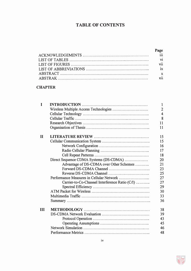
TABLE OF CONTENTS
Page
ACKNOWLEDGEMENTS .................................................... 111 LIST OF TABLES . . . . . . . . . . ,. ...... ...... ...... ...... .............. ............ VI
LIST OF FIGURES . . . . . . . . . . . . . . . . . . . . . . . . . . . . . . . . . . . . . . . . . . . . . . . . . . . . . . . . . . . . . Vll
LIST OF ABBREVIATIONS ............................................... ... IX ABSTRACT ..................................................................... X ABSTRAK . . . . . . . . . . . . . . . . . . . . . . . . . . . . . . . . . . . . . . . . . . . . . . . . . . . . . . . . . . . . . . . . . . . . . . xu
CHAPTER
I INTRODUCTION . . . . . . . . . . . . . . . . . . . . . . . . . . . . . . . . . . . . . . . . . . . . . . . . . . . 1 Wireless Multiple Access Technologies . . . . . . . . . . . . . . . . . . . . . . . . . . . . 2 Cellular Technology . . . . . . . . . . . . . . . . . . . . . . . . . . . . . . . . . . . . . . . . . . . . . . . . . . . . 4 Cellular Traffic . . . . . . . . . . . . . . . . . . . . . . . . . . . . . . . . . . . . . . . . . . . . . . . . . . . . . . . . . . 8 Research Objectives . . . . . . . . . . . . . . . . . . . . . . . . . . . . . . . . . . . . . . . . . . . . . . . . . . . . 1 1 Organisation of Thesis . . . . . . . . . . . . . . . . . . . . . . . . . . . . . . . . . . . . . . . . . . . . . . . . . . 1 1
II �ITERATURE RE"IE� . . . . . . . . . . . . . . . . . . . . . . . . . . . . . . . . . . . . .. . . . . . 1 5 Cellular Communication System . . . . . . . . . . . . . . . . . . . . . . . . . . . . . . . . . . . . . 1 5
Network Configuration . . . . . . . . . . . . . . . . . . . . . . . . . . . . . . . . . . . . . . . 16 Radio Cellular Planning . . . . . . . . . . . . . . . . . . . . . . . . . . . . . . . . . . . . . . 17 Cell Repeat Patterns . . . . . . . . . . . . . . . . . . . . . . . . . . . . . . . . . . . . . . . . . . 1 8
Direct Sequence CDMA Systems (OS-COMA) . . . . . . . . . . . . . . . . . . 20 Advantage of OS-COMA over Other Schemes . . . . . . . . . . . 2 1 Forward DS-CDMA Channel . . . . . . . . . . . . . . . . . . . . . . . . . . . . . . . . 23 Reverse OS-COMA Channel . . . . . . . . . . . . . . . . . . . . . . . . . . . . . . . . 25
Perfonnance Measures in Cellular Network . . . . . . . . . . . . . . . . . . . . . . . . 27 Carrier-to-Co-Channel Interference Ratio (CII) ... ........ 27 Spectral Efficiency . . . . . . . . . . . . . . . . . . . . . . . . . . . . . . . . . . . . . . . . . . . . 29
ATM Packet for Wireless . . . . . . . . . . . . . . . . . . . . . . . . . . . . . . . . . . . . . . . . . . . . . 30 Multimedia Traffic .. . . . . . . . . . . . . . . . . . . . . . . . . . . . . . . . . . . . . . . . . . . . . . . . . . . . 33 Summary . . . . . . . . . . . . . . . . . . . . . . . . . . . . . . . . . . . . . . . . . . . . . . . . . . . . . . . . . . . . . . . . . 36
III METHODO�OGY . . . . . . . . . . . . . . . . . . . . . . . . . . . . . . . . . . . . . . . . . . . . . . . . . . . 38 OS-COMA Network Evaluation . . . . . . . . . . . . . . . . . . . . . . . . . . . . . . . . . . . . . 39
Protocol Operation . . . . . . . . . . . . . . . . . . . . . . . . . . . . . . . . . . . . . . . . . . . . 43 Operating Assumptions . . . . . . . . . . . . . . . . . . . . . . . . . . . . . . . . . , . . . . 45
Network Simulation . . . . . . . . . . . . . . . . . . . . . . . . . . . . . . . . . . . . . . . . . . . . . . , . . . . 46 Perfonnance Metrics . . . . . . . . . . . . . . . . . . . . . . . . . . . . . . . . . . . . . . . . . . . . . . . . . . . 48
iv

Design of Experiments . . . . . . . . . . . . . . . . . . . . . . . . . . . . . . . . ........ . . . ... . . 50 Summary .... . .. . . . . . . .. . . ... . . .................. . . . . . . . . . . . .. ... . ... . .. . 5 1
IV MODEL DEVELOPMENT......................................... 53 Reverse Link DS�CDMA Model . . . . . . . . . . . . . . . . . . . . '" . . . . . . . . . . . . . . . 53
System Description and Operation . . . . . . . . . . . . . . . . . . . . . . . . . . 55 Model Description . . . . . . . . . . . . . . . . . . . . . . . . . . . . . . . . . . . . . . . . . . . . . 56 Packet Arrival . .. . . . . . . . . . . .. . . . . . . . . . . . . . . . . . . , . . . . . . . . . , . . . . . . 57 Selection of Users for Transmission . . . . . . . . . . . . . . . . . . . . . ... 58 Transmission of Packets . . . . .. . . . . . . . . . . . . . . . . . . . . . . . . . . . . . . .. 60
The Simulation Model . . . . . . . . . . . . . . ... . . . . . . . . . . . . . . . . . . . . . . . . . . . . . . . . 6 1 Entities of the Model . .. . . . . . . . . . . . . . . . . . ... . . . . . . . . . . . . . . . . ... 6 1 Transmission Buffers . . . . . . . . . . . . . . . . . . . . . . . . . . . . . . . . . . . . . . . . . 6 1 Events in the Model . . . . . . . . . . . . . . . . . . . . . . . . . . . . . . . . . . . . . . . . . . . 62 Event Scheduler . . . . . . . . . . . . . . . . . . . . . . . . . . . . . . . . . . . . . . . . . . . . . .. . 62 Simulation Algorithm . . . . . . . . . . . . . . . . . . . . . . . . . . . . . . . . . . . . . . . . . 63
Flow Diagram . . . . . . . . . . . . . . . . . . . . . . . . . . . . . . . . . . . . . . . . . . . . . . .. .. . . . . . . . .. 65 The Model Input . . . . . . . . . . . . . . . . . . . . . . . . . . . . . . . . . . . . . . . . . . . . . . . 73 The Model Output . . . . . . . . . . . . . . . . . . . . . . . . . . . . . . . . . . . . . . . . . . . . . 74
Design Limitations . .. .. . . . . . . .. . . . . . . . . . . . . . . . . . . . . . . . . . . . . . . . . . . . . . . . . 75 Summary ... .. . . . . . . . ... . . . . . . . . .. . . . . . . . . . . . . . . . . . . . . .. . . . . . . . . . . . . . . . . . 76
V RESULTS AND DISCUSSIONS . . . . . . . . . . . . . . . . . . .. . . . . . .. . . . . . . .. 78 Input Parameters . . . . . . .. . . . . . . . . . . . . . . . . . . . . . . . . . . . . . . . . . . . . . .. 78 Performance Issues . . . . . . . . . . . . . . . . . . . . . . . . .. . . . . .. . . . . . . . . . . . . 80 Results . . .. . . . . . . ... . . . . . . . . . , . . . . . . . . . . . . . . . . . . . . . . . . . . . . . . . . . . . . 8 3
Summary . . . . . .. . . . . . . . .. . . . . . . . . . . . . . . . . . . . . . . . . . . . . . . . . . . . . . . . . . . . . . . . . 1 00
VI CONCLUSIONS AND FUTURE WORK .... . . . . . . . . . . . ... . . . . . . . 1 03
REFERENCES . . . ... . . . . . . .. . . . . . . . . . . . . . . . . . . . . . . . . . . . . . . . . . . . . .. . . . . . . . . . . . 108
APPENDIX................ ... ................................................. III Appendix 1 The Simulation Model Codes . . . . . . . . . . . . . . . . . . . . . 1 12
VITA . . . . . . . . . . . . . . . . . . . . . . . . . . . . . . . . . . . . . . . . . . . . . . . . . . . . . . . . . . . . . . . . . . . . . . . . . 1 20
v

LIST OF TABLES
Table Page
1.1 Comparisons Of Access Technologies ........ ....... ... 4
2.1 Traffic Capacity and Co-channel Interference . . . . . . . . . 20
2.2 Packet Service and Delay Requirements . . . . . . . ... . . . . . 3 1
vi
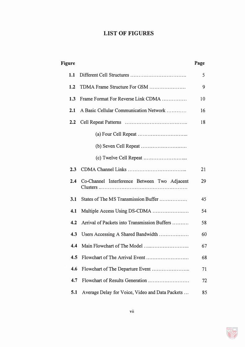
LIST OF FIGURES
Figure Page
1.1 Different Cell Structures.................................. 5
1.2 TDMA Frame Structure For GSM .... ..... . . . . .. . .. .... 9
1.3 Frame Format For Reverse Link CDMA . ...... .. . . . . .. 1 0
2.1 A Basic Cellular Communication Network . . . . , . . . . . . . 16
2.2 Cell Repeat Patterns . . . .. . . .. . . . . .. . .. . .. . . . . . . . . . . . . . . . . , 18
(a) Four Cell Repeat .............................. .
(b) Seven Cell Repeat ........................... .
(c) Twelve Cell Repeat .......................... .
2.3 CDMA Channel Links . .. ... . . . ... .. . . . . . . . . . . . . . . . . . . . . . . 21
2.4 Co-Channel Interference Between Two Adjacent 29 Clusters .. . . . . . . . . . . . . . . . . . . . . . . . . . . . . . . . . . . . . . . . . . . . . . . . . . . . .
3.1 States of The MS Transmission Buffer ................. 45
4.1 Multiple Access Using DS-CDMA ...................... 54
4.2 Arrival of Packets into Transmission Buffers ......... , 58
4.3 Users Accessing A Shared Bandwidth .................. 60
4.4 Main Flowchart of The Model ............................ 67
4.5 Flowchart of The Arrival Event .......................... 68
4.6 Flowchart of The Departure Event .................. ... " 71
4.7 Flowchart of Results Generation ......................... 72
5.1 Average Delay for Voice, Video and Data Packets .. , 85
vii

5.2 Throughput of Different Traffic Types for Different 8S Threshold Values .......................................... .
5.3 Queue Length of Different Traffic Types. .. . . . . . . . . .... 87
5.4 Blocking Rate of Voice, Video and Data Packets..... 87
5.5 Average Video Delay for A Threshold Value of 20 89 for 1 to 4 Video Users .................................... ,
5.6 Average Voice Delay for A Threshold Value of 20 89 for 1 to 4 Video Users .................................... .
5.7 Average Data Delay for A Threshold Value of20 for 91 1 To 4 Video Users ....................................... .
5.8 Traffic Throughput for Threshold Value of 20 for 1 91 to 4 Video Users .......................................... .
5.9 Average Queue Length for All Traffic Types for A 93 Threshold Level of20 For 1 to 4 Video Users ........ .
5.10 Blocking Rate with A Threshold Value of20 for 1 to 93 4 Video Users . . . . . . . . . . . . . . . . . . . . . . . . . . . . . . . . . . . . . . . . . . . . . .
5.11 Average Delay of Voice, Video and Data for 9S Different Data Access Priority .......................... .
5.12 Average Queue Length of Data for Different Data 95 Access Priority with A Threshold Value of 20 ....... .
5.13 Average Packet Delay for Increasing Video Access 97 Priority with A Nominal Threshold Value of20 ..... .
5.14 Average Delay of Asynchronous Video and 97 Synchronous Video ...................................... .
5.15 Throughput of Asynchronous Video and 99 Synchronous Video ...................................... .
5.16 Average Queue Length of Asynchronous Video and 99 Synchronous Video ...................................... .
5.17 The Capacity of Mixed Voice, Video and Data Users 100
Vlll

AMPS
ATM
BER
BS
CDMA
D-AMPS
DS-CDMA
FCFS
FDM
FDMA
FM
GSM
IC
IDWAN
MAC
MHz
MS
MSC
TDMA
NA-TDMA
NMT
PN
PRMA
PSTN
RF
SNR
TACS
LIST OF ABBREVIATIONS
Advance Mobile Phone System
Asynchronous Transfer Mode
Bit Error Rate
Base Station
Code Division Multiple Access
Digital Advance Mobile Phone System
Direct Sequence Code Division Multiple Access
First Come First Serve
Frequency Division Modulation
Frequency Division Multiple Access
Frequency Modulation
Global Service for Mobile
Integrated Circuit
Integrated Digital Wireless Access Network
Media Access Control
Megahertz
Mobile Station
Mobile Switching Center
Time Division Multiple Access
North American Time Division Multiple Access
Nordic Mobile Telephone
Pseudonoise
Packet Reservation Multiple Access
Public Switched Telephone Network
Radio Frequency
Signal to Noise Ratio
Total Access Communication Systems
ix

Abstract of thesis presented to the Senate of the Universiti Putra Malaysia in fulfilment of the requirements for the degree of Master of Science.
PERFORMANCE STUDIES OF MULTIMEDIA TRAFFIC IN CDMA CELLULAR NETWORK
By
MADRA V AN BALAN NAIR
February 1999
Chairman: Associate Professor Ashwani Kumar Ramani, Ph.D.
Faculty: Computer Science and Information Technology
The current generation of wireless cellular network is mostly used for voice
communication. Although data services such as short message services (SMS) are
available, voice communication still takes precedence. However, in the near
future, it is anticipated that wireless communication is expected to handle
multimedia traffic that is currently available on land networks. Multimedia traffic
includes video services such as real time video and audio, voice services and data
services similar to the ones available in the Internet. The cellular network carrying
multimedia traffic is analysed in a single cell where Code Division Multiple
Access (CDMA) protocol is used for users to access the network simultaneously.
The study is analysed for the reverse link communication, i. e. , communication
between the user and the base station. CDMA is used because of its merits in
minimising the effect of interference, increasing cell capacity and high security
features compared to other access technologies. The model inputs include co�
channel interference, signal to noise ratio, bit error rate requirements, number of
x
users, the channel access priority and threshold. Suitable assumptions to enable
simulation are made. The model is simulated to see the impact of complementing
data traffic along with voice and video traffic. The model is also simulated for
synchronous transmission and asynchronous transmission of packets. The results
shows that data traffic can be successfully complemented along with voice and
video traffic without significantly degrading voice and video delay. Data traffic
can tolerate delay but is loss sensitive. Data traffic delay can be used without
suffering any loss, even by reducing the data access priority. The model also
compared the effects of synchronous and asynchronous transmission.
Synchronous transmission indicated an overhead in packet delay compared to
asynchronous transmission. It is concluded from the work that voice, video and
data traffic can be served in a cell simultaneously with asynchronous transmission.
A higher bandwidth can assure a higher number of multimedia users in a
asynchronous CDMA cellular network. The model will serve as a useful design
tool.
xi

Abstrak tesis yang dikemukakan kepada Senat Universiti Putra Malaysia sebagai memenuhi keperluan untuk ijazah Master Sains.
ANALISA RANGKAIAN CELLULAR CDMA MEMBA WA TRAFIK MULTIMEDIA
Oleh
MADRA V AN BALAN NAIR
F ebruari 1 999
Pengerusi: Profesor Madya Ashwani Kumar Ramani, Ph.D.
Fakulti: Sains Komputer dan Teknologi Maklumat
Rangkaian komunikasi selular (bimbit) tanpa wayar masa kini, lazimnya
digunakan untuk komunikasi suara. Walaupun perkhidmatan data seperti
perkhidmatan mesej singkat wujud, komunikasi suara diberi keutamaan. Walau
bagaimanapun, dijangka pada masa akan datang, komunikasi melalui udara
mampu memberi perkhidmatan multimedia yang kini didapati pada rangkaian
daratan. Perkhidmatan multimedia merangkumi video dan audio langsung,
perkhidmatan suara dan juga perkhidmatan yang boleh diperolehi melalui internet.
Analisis rangkaian multimedia yang menampung perkhidmatan multimedia dibuat
dalam suasana sebuah sel di mana protokol "Code Division Multiple Access
(COMA)" digunakan untuk membolehkan pengguna memasuki rankaian tersebut
secara serentak. Analisis ini dilakukan untuk komunikasi antara peggguna dan
stesen tapak rangkaian. CDMA digunakan kerana kelebihannya mengurangkan
kesan gangguan, meningkatkan kebolehan sel dan mempunyai ciri-ciri
keselamatan yang ketat berbanding dengan teknologi laluan yang lain. Input untuk
xii

model ini ialah ganguan antara pengguna, nisbah isyarat kepada bunyi, bilangan
pengguna, keutarnaan laluan dan saiz laluan serentak. Andaian yang sesuai dibuat
untuk membolehkan simulasi dijalankan. Model ini disimulasi untuk memerhati
kesan menyesuaikan perhidmatan data bersarna perkhidmatan suara dan video. Ia
juga disimulasikan untuk penghantaran berkala dan tak berkala. Keputusan
menunjukkan bahawa perkhidmatan data boleh diselitkan bersarna-sama
perkhidmatan video dan suara tanpa mengganggu kelambatan dalarn perkhidmatan
video dan suara. Perkhidmatan data boleh menerima penangguhan tetapi sensitif
terhadap kehilangan. Perkhidmatan data boleh digunakan tanpa menanggung
sebarang kehilangan meskipun keutarnaan data dikurangkan. Model ini juga
membezakan transmisi berkala dan transmisi tidak berkala. Transmisi berkala
menunjukan penarnbahan dalarn kelarnbatan perkhidmatan video berbanding
dengan transmisi tak berkala. Kesimpulannya ialah, perkhidmatan data, video dan
suara dapat diberikan secara serentak dalarn suasana sebuah sel secara tak berkala.
"Bandwidth" yang lebih tinggi membolehkan lebih rarnai pengguna menggunakan
rangkaian selular tak berkala CDMA. Model in boleh digunakan sebagai satu alat
rekabentuk yang berguna.
Xlii

CHAPTER I
INTRODUCTION
The electronic wireless communication can be traced back since the time of
Thomas Edison and Guglielmo Marconi about lOO years back. Early research on
portable communication was carried out over 40 years ago by AT&T bell labs. In
the 1 960's, Motorola continued the task and came out with the first mobile cellular
telephone service in the early 1 980's (William W.E, 1 993). With the advancement
in semiconductor and IC packaging technology, a dramatic reduction in cost and
size of communication equipment have boosted the wireless industry.
The first generation systems were cellular phones with wide area coverage.
The others were residential cordless phones. Analogue FM voice signal was used.
In the second generation, cellular phones with small cell (area) coverage were
implemented. Each cell would communicate to the nearest base station. Cordless
phones with expanded area coverage were introduced. Digital voice signal is used
rather than the conventional analogue FM. In the third generation, a convergence
of cellular, cordless and paging will be introduced which will develop the
Integrated Digital wireless Access Network (IDW AN) (Alphna Doshi, 1 997).

2
This generation of wireless communications will be strongly dominated by
multimedia traffic. One of the most serious challenges is the design of an efficient
and robust medium access control (MAC) protocol that can integrate
heterogeneous traffic types and meet their requirement of quality of service. In the
following section, we explain the currently available access protocols that are used
in wireless communication.
Wireless Multiple Access Technologies
In wireless communication, there are several mUltiple access technologies
such as FDMA, TDMA and CDMA.
Frequency Division Multiple Access (FDMA) is an access technology
where every user needs a different frequency bands to access the network. It only
needs a distinctive radio frequency for each user and the receiver has to only tune
to that particular frequency. Since an analogue radio frequency (RF) is sent, this
technology does not need a digitised speech decoder. This is a narrow-band
technology.
The advantage of this technology is that it is simple and inexpensive as RF
1S used to propagate the signals. Terminal power amplifiers only needs to
accommodate actual transmit power. The limitations of these technology is, it
needs a radio transceiver unit in the base station for each voice channel. The
allowable tolerance on the frequency source is less due to the narrow channel

3
width. Because of this limitation, the bandwidth for this technology is limited and
thus cannot support a large number of users.
Time Division Multiple Access (TDMA) is similar to FDMA except that
each RF frequency is partitioned into time slots. With this technology, a singleRF
channel can carry multiple users where each user is assigned to their own time
slots. The bandwidth per channel is now proportional to the number of time slots.
Because a single RF may carry multiple users with different time slots, a digital
speech coding is required.
Opposed to FDMA, TDMA requires less numbers of RF frequencies for a
given voice circuit capacity. It also gives flexibility in providing capacity to
individual users as slots are allocated to each user. Because time is slotted, an
additional delay in the speech path is seen compared to FDMA. Bandwidth is also
limited in this technology as interference is the main limitation.
Code Division Multiple Access (CDMA) is a spread spectrum technology
where multiple users operate on the same band simultaneously but their signals are
distinguished by being encoded with different high rate spreading sequences. In
spread spectrum technology, signals are spread over a much wider frequency band
than would ordinarily required by their information content.
The original information-bearing signal is combined with a pseudo-random
signal. The end product of this resembles a white noise. This signal will appear to

4
be background noise to conventional receivers. Only a receiver with the correct
pseudo-random spreading code can recover the original user information.
Because of spread spectrum technology, the capacity of users is said to be
unlimited (Shuzo Kato, 1997). The only limitation is not the technology but the
electronic device and cost itself. The need for cell site frequency is eliminated, as
no spectrum would be the same. The speech activity is said to be smoother
compared to TDMA and FDMA architecture (Viterbi, 1995). Because it is still a
new technology in the cellular (wireless) market, the performance is still very
uncertain. Spread spectrum is a complex technology requiring sophisticated base-
band digital processing.
A summary of the comparison between these three access technologies is
shown in Table 1 . 1 .
Table 1.1: Comparisons of Access Technologies
FDMA TDMA CDMA Circuits per RF carrier single Multiple Unlimited Transmission Continuous Burst Either RF Bandwidth Narrow Medium/wide very wide Mobile Complexity Low High High Shared system cost High Low Low
Cellular Technology
The cellular technology has provided a breakthrough in wireless
communication by providing access to a large number of users. This is possible by
5
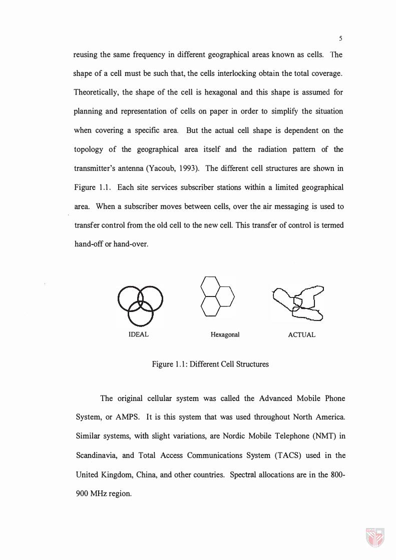
reusing the same frequency in different geographical areas known as cells. The
shape of a cell must be such that, the cells interlocking obtain the total coverage.
Theoretically, the shape of the cell is hexagonal and this shape is assumed for
planning and representation of cells on paper in order to simplify the situation
when covering a specific area. But the actual cell shape is dependent on the
topology of the geographical area itself and the radiation pattern of the
transmitter's antenna (Yacoub, 1 993). The different cell structures are shown in
Figure 1 . 1 . Each site services subscriber stations within a limited geographical
area. When a subscriber moves between cells, over the air messaging is used to
transfer control from the old cell to the new cell. This transfer of control is termed
hand-off or hand-over.
IDEAL Hexagonal ACTUAL
Figure 1 . 1 : Different Cell Structures
The original cellular system was called the Advanced Mobile Phone
System, or AMPS. It is this system that was used throughout North America.
Similar systems, with slight variations, are Nordic Mobile Telephone (NMT) in
Scandinavia, and Total Access Communications System (TACS) used in the
United Kingdom, China, and other countries. Spectral allocations are in the 800-
900 MHz region.
6
Traditionally radio communication systems have separated users either by
frequency channels, time slots, or both. These concepts dated back from the
earliest days of radio. Even spark transmitters used resonant circuits to narrow the
spectrum of their radiation. Scheduled net operation was probably the first
manifestation of time slotting (John Escher, 1997). Modem cellular systems began
with the use of channelised analogue FM. More recently several hybrid FDM
TDM digital systems have been developed extensively, to enhance service quality
and capacity. In all these systems, each user is assigned a particular time
frequency slot. In large systems the assignments to the time-frequency slots cannot
be unique. Slots must be reused in multiple cells in order to cover large service
areas. Satisfactory performance in these systems depends critically on control of
the mutual interference arising from the reuse. The reuse concept is familiar even
in television broadcasting, where channels are not reused in adjacent cities.
CDMA offers an answer to the capacity problem. The key to its high
capacity is the use of noise-like carrier waves, as was first suggested decades ago
by Claude Shannon (Shannon C.E, 1949). Instead of partitioning either spectrum
or time into disjoint "slots" each user is assigned a different instance of the noise
carrier. While those waveforms are not rigorously orthogonal, they are nearly so.
Practical application of this principle has always used digitally generated pseudo
noise, rather than true thermal noise. The basic benefits are preserved, and the
transmitters and receivers are simplified because large portions can be
implemented using high-density digital devices (Lathi B.P, 1998).

7
The major benefit of noise-like carriers is that the system sensitivity to
interference is fundamentally altered. Traditional time or frequency slotted
systems must be designed with a reuse ratio that satisfies the worst-case
interference scenario, but only a small fraction of the users actually experience that
worst-case. Use of noise-like carriers, with all users occupying the same spectrum
makes the effective noise, the sum of all other-user signals. The receiver
correlates its input with the desired noise carrier, enhancing the signal to noise
ratio at the detector. The enhancement overcomes the summed noise enough to
provide an adequate SNR (signal to noise ratio) at the detector. Because the
interference is summed, the system is no longer sensitive to worst-case
interference, but rather to average interference.
CDMA was initially used in American Army and not exposed to the public
because of its high security features. Because this technology uses digital coded
random signal for transmission, it was impossible for intruders to detect
information transmitted in this form. This clearly indicates the advance security
features of CDMA compared to other access schemes.
The demand for mobile communication has increased tremendously over
the years. Although initially, voice communication was the only demand catered
in wireless, now new services such as, video on demand, multimedia traffic is
needed because of the mobility of wireless communication. This brings new
challenges such as increased bandwidth allocation for mobile, servicing more users
in constrained environment and catering for various traffic types.

8
Although there are several types of MAC protocol designed for CDMA
system, they are typically not intended for a cellular structure. For example, the
packet CDMA in (A. Sheikh, 1994) is intended for a mesh network of quasi-static
users. On the other hand, tho�e that are designed to take advantage of the cellular
structure, such as, C-PRMA (G. Bianchi, 1 994), R-ISMA (G. Wu, 1 994) or PRAP
(C.C. Lu, 1 994), do not take advantage of the DS/CDMA scheme. In addition,
protocols of the type DS/CDMA ALOHA (Z. Liu, 1 994) were not designed and
evaluated for the case of heterogeneous traffic. Thus, a suitable scheme has to be
implemented to accommodate these various types of traffics. New challenges and
the future direction of wireless data can be found in (Alphna Doshi, 1 997).
Cellular Traffic
In a cellular network, data is transmitted in the form of frames. The
duration (size) of a frame is dependent on the type of multiple access scheme used.
Global Service for Mobile (GSM) and NA-TDMA uses a TDMA frame format. In
GSM, the size of a frame is 4 .6 1 5 ms. Each frame is further divided into 8 time
slots. Each slot is 1 56 bits (0 .577 ms). The frame structure is shown in Figure 1 .2.
There are also mUltiple frame structures such as multiframe (l20ms), superframe
(6. 12 s) and hyperframe (3.48 h). A larger frame allows maximum throughput on
the system but under noisy condition, a larger frame is prone to higher error rate.
A suitable frame size has to be selected. Frames are usually divided into smaller
blocks before being transmitted. This reduces the error rate due to large frame
size.

(Bits) 3
TDMA frame (4.615ms) �.I
\01 Q2pI4!s\6\7\
t Encrypted bits Training
sequence Encrypted bits
58 26 58
Figure 1.2: TDMA Frame Structure for GSM
9
3
For a reverse link CDMA channel, a variable data rate of 9600,4800, 2400
or 1200 bps are available. All of these frame sizes are 20 ms. The size of
information bits that can be carried by each frame is dependent on the data rate.
The higher the data rate, the more information bits can be carried in a frame. A
data rate of 9600 bps can carry 172 bits while a data rate of 1200 bps can carry 16
bits of information in a frame. The actual burst transmission rate is fixed at 28800
code symbols per second. With a higher transmission rate, more bits can be sent
such as video streams.
The frame structure is shown in Figure 1.3. The contents of each frame are
information bits (size dependent on bit rate), the corresponding forward CDMA
channel (frame quality indicator) and tail bits (8 bits). Two different frame types
were explained above but there are also other frame structures for different access
protocols. TDMA frames are the most commonly used and they are divided into
slots. Each frame has a fixed size. In CDMA however, although frame duration is
constant (20 ms) but the information bits in each frame can vary depending on the

10
available bit rate. Both protocols are able to handle high bit rate traffic such as
video by expending their frame structure accordingly. Frame size in the form of
ATM packets is also discussed in (A.1. Mueller, 1994).
I lnfonnation bits (1) I F I T I � 20ms ---..�
Figure 1.3: Frame Format for Reverse Link CDMA
In a mobile cellular network, traffic can be classified as transmission with
high traffic rates and transmission with lower traffic rates. High rate traffic has a
lower burst rate (such as video) and lower traffic rates has high burst rates (such as
text). But video traffic is more tolerant to delay compared to voice traffic which is
less tolerant. On the other hand, data traffic is highly loss sensitive and loss of
data packet must be avoided. A buffer can mitigate the burstyness of video packet
and a large buffer size can prevent the lost of data packet. A suitable scheme has to
be adapted to these different traffic types, where different traffics have its own
characteristics.
In this work, a cellular DS/CDMA network carrying multimedia traffic
types is evaluated. An important feature of this MAC protocol is its simplicity.
An outline of this protocol can be found in (Roman Pichna, 1995) for the case of
two traffic types. The following section outlines the objectives of this work.
11
Research Objectives
The environment in a single cell with multiple users is studied. The
CDMA protocol that can handle simultaneous users are assumed for this study.
Transmission from the user to the base station is (reverse link) taken for this study.
The primary goal of this research is to:
• Study the behaviour of the network with different traffic types such as data,
voice and video. Although traffic can be categorised in different hybrids, these
three traffic are most common.
• Study the different schemes in handling the multimedia traffic in terms of
packet delay and blocking at the lowest level.
• Study the suitability of the service schemes by investigating the performance
measures, obtained from the simulation.
• Study the effect of complementing data traffic along With voice and video
traffic in the cell.
Organisation of Thesis
Chapter II presents the related literature reviewed in the concerned area. In
this chapter the architecture of a basic cellular network is introduced. The


