What is VHDL? • A hardware description language that can be used to model a digital system. • VHDL = V HSIC H ardware D escription L anguage • V ery H igh S peed I ntegrated C ircuit • Can describe: - behaviour, - structure, and - timing of a logic circuit.
Transcript
What is VHDL?
• A hardware description language that can be usedto model a digital system.
• VHDL = VHSIC Hardware Description Language• Very High Speed Integrated Circuit
• Can describe:− behaviour,− structure, and− timing
of a logic circuit.
Hardware Modelling in VHDL
• VHDL is NOT a programming language like C orJava.
• It is used to model the physical hardware used indigital systems.
• Therefore you must always think about the hardwareyou wish to implement when designing systems usingVHDL.
Abstraction HierarchyIncreasingAbstraction
System Concept
Algorithm
RTL (Register Transfer Level)
Gate
Transistor IncreasingComplexity
Data Objects
• A data object holds a value of a specified type.
• The data objects that can be synthesized directly inhardware are:
1. Signal: Represents a physical wire in a circuit.It holds a list of values which includes its currentvalue and a set of possible future values.
2. Var iable: Used to hold results of computations.It does not necessarily represent a wire in acircuit.
3. Constant: Contains a value that cannot bechanged. It is set before the beginning of asimulation.
Predefined Data Types
• Standard logic type: STD_LOGIC,STD_LOGIC_VECTOR(Can hold 0, 1, Z, and −−.)
• Bit type: BIT, BIT_VECTOR
• Integer type: INTEGER
• Floating−point type: REAL
• Physical type: TIME
• Enumeration type: BOOLEAN, CHARACTER
• To use the STD_LOGIC andSTD_LOGIC_VECTOR types, the std_logic_1164package must be included in the VHDL design file.
• We can define our own data types. This isespecially useful when designing finite−state machines(FSMs).
• An object declaration is used to declare an object, itstype, its class, and optionally to assign it a value.
Object Declaration Examples
• Signal declarations:SIGNAL sresetn : STD_LOGIC;SIGNAL address : STD_LOGIC_VECTOR(7
downto 0);
• Variable declarations:VARIABLE index : INTEGER range 0 to 99 :=
• A concurrent assignment statement is used to assigna value to a signal in an architecture body.
• Used to model combinational circuits.
• The order in which these statements occur does notaffect the meaning of the code.
2x4 Decoder Example
decoder2x4
A
B
EN
Z4
LIBRARY ieee;USE ieee.std_logic_1164.all;
ENTITY decoder2x4 ISPORT (A, B, EN : IN STD_LOGIC;
Z : OUT STD_LOGIC_VECTOR(3 downto 0));END decoder2x4;−−this is a comment
Architecture Body of 2x4 Decoder
ARCHITECTURE dec_df OF decoder2x4 ISSIGNAL ABAR, BBAR : STD_LOGIC;
BEGIN−−Order of concurrent signal assignmentstatements is not important.Z(3) <= not (A and B and EN); Z(0) <= not (ABAR and BBAR and EN);BBAR <= not B;Z(2) <= not (A and BBAR and EN);ABAR <= not A;Z(1) <= not (ABAR and B and EN);
END dec_df;
Sequential Assignment Statements
• Sequential assignment statements assign values tosignals and variables. The order in which thesestatements appear can affect the meaning of the code.
• Can be used to model combinational circuits andsequential circuits.
• Require use of the PROCESS statement.
• Include three variants: IF statements, CASEstatements, and LOOP statements.
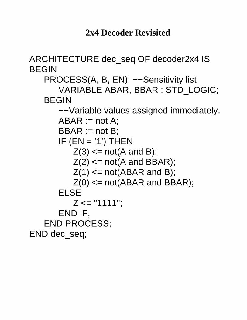
BEGIN−−Variable values assigned immediately.ABAR := not A; BBAR := not B;IF (EN = ’1’) THEN
Z(3) <= not(A and B); Z(2) <= not(A and BBAR);Z(1) <= not(ABAR and B);Z(0) <= not(ABAR and BBAR);
ELSEZ <= "1111";
END IF;END PROCESS;
END dec_seq;
IF and CASE Statements
• IF and CASE statements are used to modelmultiplexers, decoders, encoders, and comparators.
• Can only be used in a PROCESS.
Modelling a 4−1 Multiplexer
Using an IF statement: Using a CASE statement:
PROCESS (Sel, A, B, C, D)BEGIN
IF (Sel = "00") THENY <= A;
ELSIF (Sel = "01")THEN
Y <= B;ELSIF (Sel = "10")
THENY <= C;
ELSEY <= D;
END IF;END PROCESS;
PROCESS (Sel, A, B, C, D)BEGIN
CASE Sel ISWHEN "00" => Y <= A;WHEN "01" => Y <= B;WHEN "10" => Y <= C;WHEN "11" => Y <= D;WHEN OTHERS =>Y
<=A;END CASE;
END PROCESS;
• Can also model multiplexers with WHEN/ELSEclause and WITH/SELECT clause. These can only beused outside of a PROCESS.
FSM Example
IDLE
SEND RECEIVE
DONEFIN = ’1’
READ = ’1’
FIN = ’1’
WRITE = ’1’
LIBRARY ieee;USE ieee.std_logic_1164.all;
ENTITY Controller ISPORT ( Write, Read, Fin : IN STD_LOGIC;
Busy, Snd, Rec, Dn : OUT STD_LOGIC;Clock : IN STD_LOGIC;Reset : IN STD_LOGIC);
END Controller;
FSM Example Continued
IDLE
SEND RECEIVE
DONEFIN = ’1’
READ = ’1’
FIN = ’1’
WRITE = ’1’
ARCHITECTURE My_FSM OF Controller ISTYPE State_Type IS (Idle, Send, Receive,
Done);SIGNAL State : State_Type;
BEGINPROCESS(Reset, Clock)BEGIN
IF Reset=’1’ THENState <= Idle;
ELSIF(Clock’EVENT and Clock=’1’) THENCASE State IS
WHEN Idle =>IF Read=’1’ THEN
State <= Receive;ELSIF Write=’1’ THEN
State <= Send;ELSE
State <= Idle;END IF;
FSM Example Continued
IDLE
SEND RECEIVE
DONEFIN = ’1’
READ = ’1’
FIN = ’1’
WRITE = ’1’
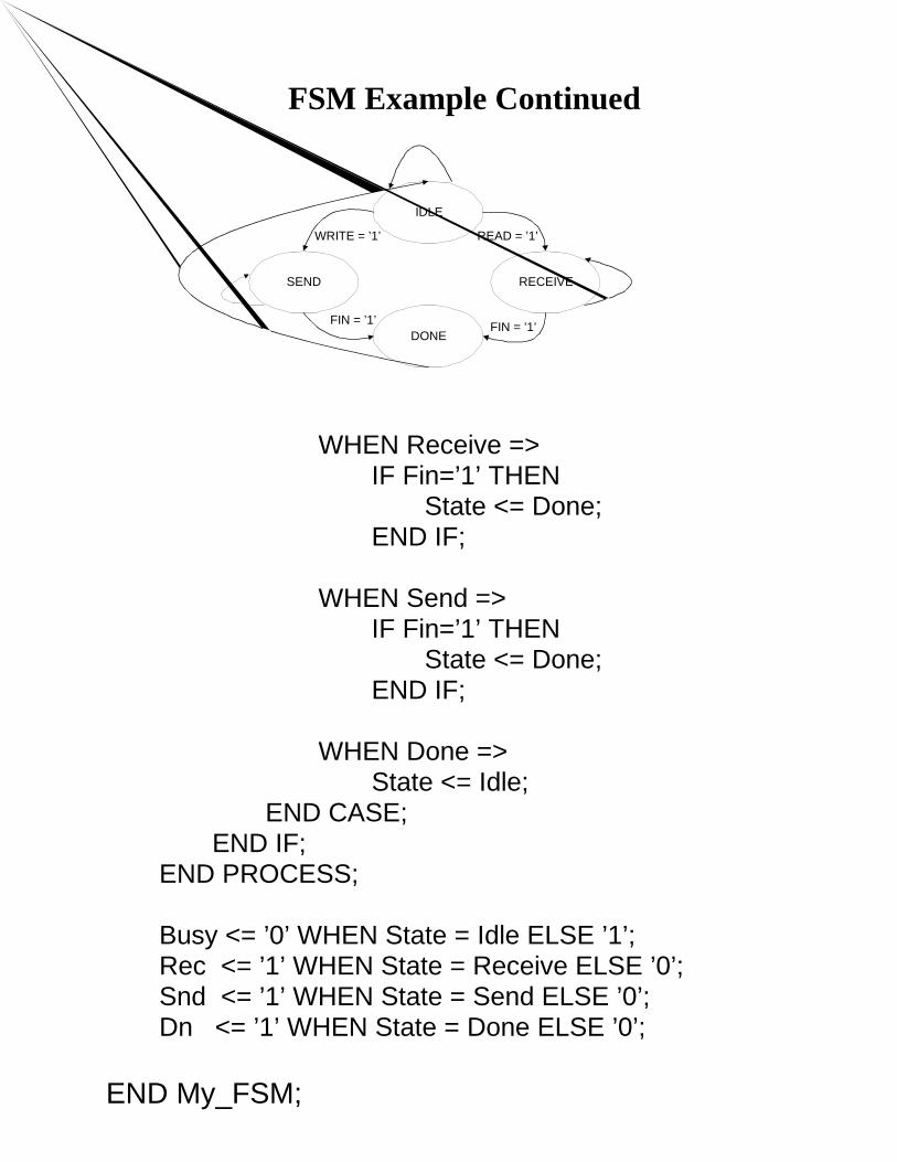
WHEN Receive =>IF Fin=’1’ THEN
State <= Done;END IF;
WHEN Send =>IF Fin=’1’ THEN
State <= Done;END IF;
WHEN Done =>State <= Idle;
END CASE;END IF;
END PROCESS;
Busy <= ’0’ WHEN State = Idle ELSE ’1’;Rec <= ’1’ WHEN State = Receive ELSE ’0’;Snd <= ’1’ WHEN State = Send ELSE ’0’;Dn <= ’1’ WHEN State = Done ELSE ’0’;
END My_FSM;
Behavioural vs. Structural Modelling
• With VHDL, we can describe the behaviour ofsimple circuit building blocks and then use these tobuild up the structure of a more complex circuit.
• Behavioural modelling is useful because it allowsthe designer to build a logic circuit without having toworry about the low−level details.
• Structural modelling is useful because it tells thesynthesis tools exactly how to construct a desiredcircuit.
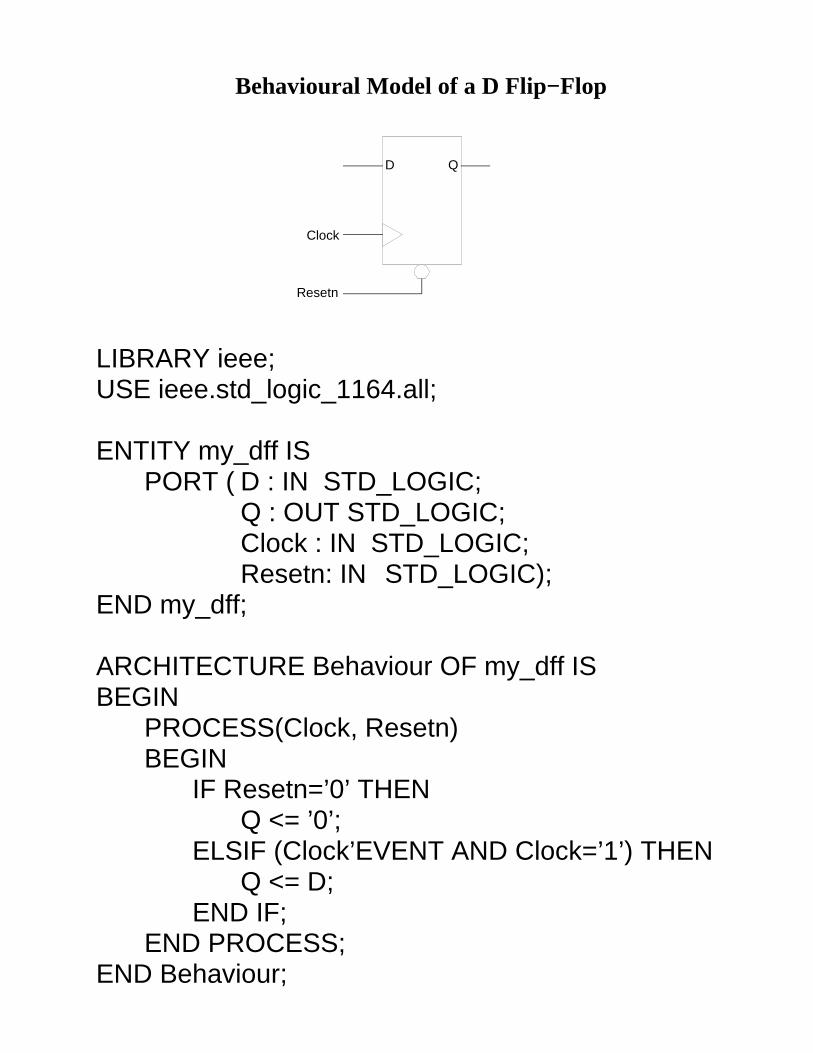
Behavioural Model of a D Flip−Flop
D Q
Clock
Resetn
LIBRARY ieee;USE ieee.std_logic_1164.all;
ENTITY my_dff ISPORT ( D : IN STD_LOGIC;
Q : OUT STD_LOGIC;Clock : IN STD_LOGIC;Resetn: IN STD_LOGIC);
END my_dff;
ARCHITECTURE Behaviour OF my_dff ISBEGIN
PROCESS(Clock, Resetn)BEGIN
IF Resetn=’0’ THENQ <= ’0’;
ELSIF (Clock’EVENT AND Clock=’1’) THENQ <= D;
END IF;END PROCESS;
END Behaviour;
Behavioural Model of a 4−Bit Shift Register
LIBRARY ieee;USE ieee.std_logic_1164.all;
ENTITY shift_reg_behav ISPORT ( Data_IN : IN STD_LOGIC;
Data_OUT : OUT STD_LOGIC;Clock, Resetn : IN STD_LOGIC);
END shift_reg_behav;
ARCHITECTURE Behaviour OF shift_reg_behav ISSIGNAL Shift : STD_LOGIC_VECTOR(3 downto
0);BEGIN
PROCESS(Clock, Resetn)BEGIN
IF Resetn=’0’ THENShift <= "0000";
ELSIF (Clock’EVENT AND Clock=’1’) THENShift(3) <= Data_IN;−−shift data to the rightShift(2 downto 0) <= Shift(3 downto 1);
END IF;END PROCESS;
Data_OUT <= Shift(0);
END Behaviour;
Structural Model of a 4−Bit Shift Register
D Q D Q D Q D QData_IN Data_OUT
Clock
Resetn
DFF_3 DFF_2 DFF_1 DFF_0
Q3_out Q2_out Q1_out
LIBRARY ieee;USE ieee.std_logic_1164.all;
ENTITY shift_reg_struct ISPORT (Data_IN : IN STD_LOGIC;
Data_OUT: OUT STD_LOGIC;CLK, RESN : IN STD_LOGIC);
END shift_reg_struct;
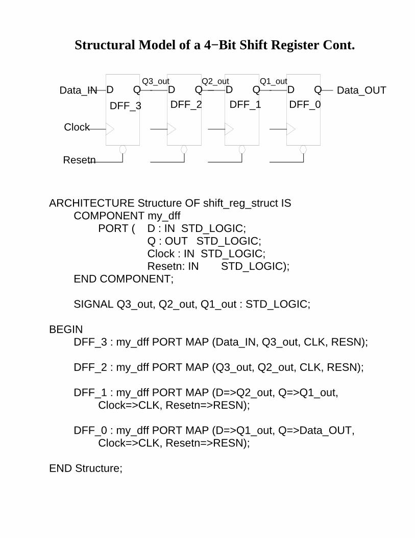
Structural Model of a 4−Bit Shift Register Cont.
D Q D Q D Q D QData_IN Data_OUT
Clock
Resetn
DFF_3 DFF_2 DFF_1 DFF_0
Q3_out Q2_out Q1_out
ARCHITECTURE Structure OF shift_reg_struct ISCOMPONENT my_dff
PORT ( D : IN STD_LOGIC;Q : OUT STD_LOGIC;Clock : IN STD_LOGIC;Resetn: IN STD_LOGIC);
END COMPONENT;
SIGNAL Q3_out, Q2_out, Q1_out : STD_LOGIC;
BEGINDFF_3 : my_dff PORT MAP (Data_IN, Q3_out, CLK, RESN);
DFF_2 : my_dff PORT MAP (Q3_out, Q2_out, CLK, RESN);
DFF_1 : my_dff PORT MAP (D=>Q2_out, Q=>Q1_out, Clock=>CLK, Resetn=>RESN);
DFF_0 : my_dff PORT MAP (D=>Q1_out, Q=>Data_OUT, Clock=>CLK, Resetn=>RESN);
END Structure;
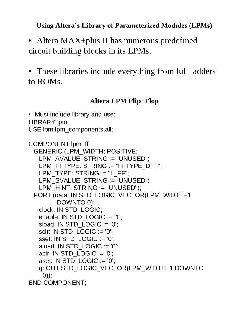
Using Altera’s L ibrary of Parameter ized Modules (LPMs)
• Altera MAX+plus II has numerous predefinedcircuit building blocks in its LPMs.
• These libraries include everything from full−addersto ROMs.
Altera LPM Flip−Flop
• Must include library and use:LIBRARY lpm;USE lpm.lpm_components.all;
DOWNTO 0); clock: IN STD_LOGIC; enable: IN STD_LOGIC := ’1’; sload: IN STD_LOGIC := ’0’; sclr: IN STD_LOGIC := ’0’; sset: IN STD_LOGIC := ’0’; aload: IN STD_LOGIC := ’0’; aclr: IN STD_LOGIC := ’0’; aset: IN STD_LOGIC := ’0’; q: OUT STD_LOGIC_VECTOR(LPM_WIDTH−1 DOWNTO
0));END COMPONENT;
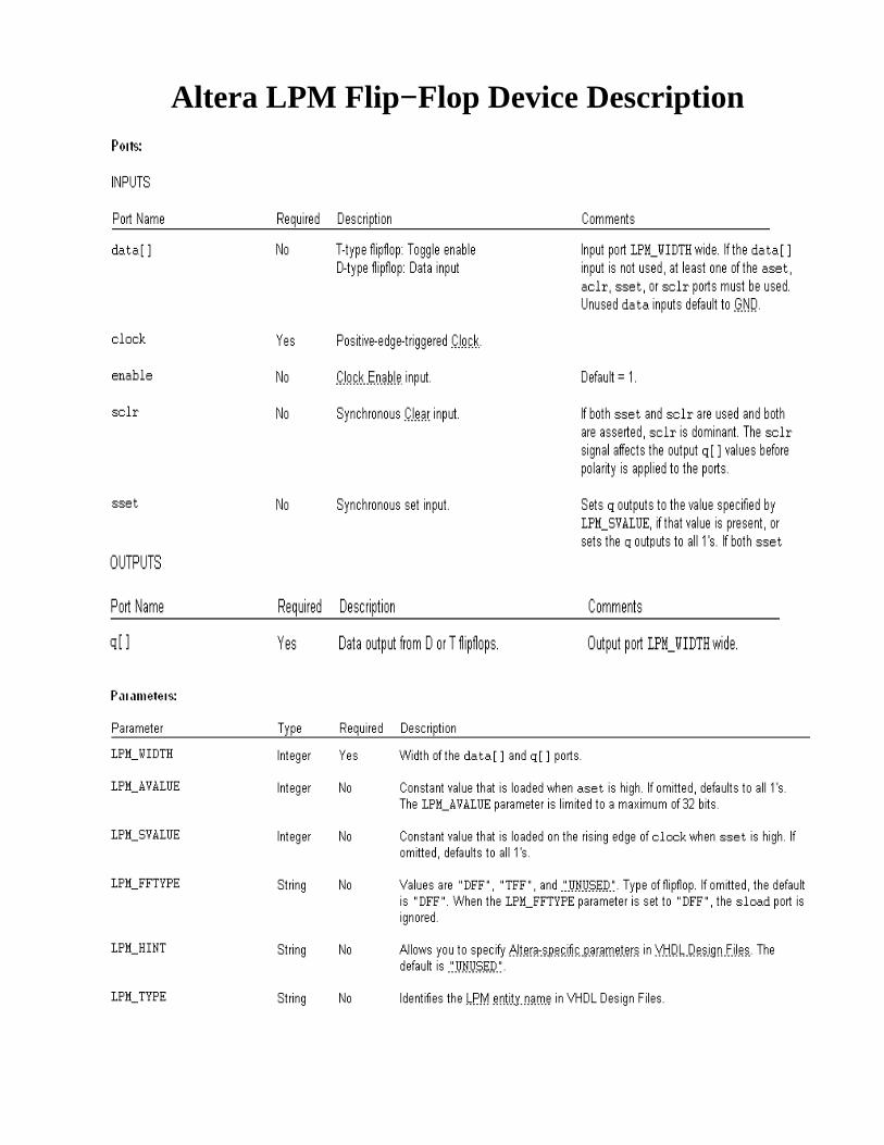
Altera LPM Flip−Flop Device Descr iption
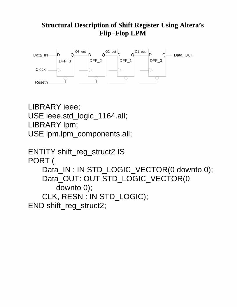
Structural Descr iption of Shift Register Using Altera’sFlip−Flop LPM