24
WALK-BEHIND TROWELS B424 – B430 – BC436 – BC446 – B436 – B446 – MEGA-T B446 OWNER’S MANUAL www.BARTELLGLOBAL.com Doc. # OI-B19001 Orig. Rel. – 08/2016 Curr Rev. - 01
| Date post: | 03-Jul-2018 |
| Category: |
Documents |
| Upload: | nguyenthuy |
| View: | 226 times |
| Download: | 0 times |

WALK-BEHIND TROWELS
B424 – B430 – BC436 – BC446 – B436 – B446 – MEGA-T B446
OWNER’S MANUAL
www.BARTELLGLOBAL.com
Doc. # OI-B19001
Orig. Rel. – 08/2016 Curr Rev. - 01

WALK-BEHIND TROWELS OI – B19001
OWNER’S MANUAL
1
www.BARTELLGLOBAL.com
Bartell Morrison Inc.
375 Annagem Boulevard Mississauga, Ontario, Canada
L5T 3A7 Tel: (647) 953-4100 Fax: (647) 953-4101
Bartell Morrison USA LLC 200 Commerce Drive, Unit A
Freehold, NJ, USA 07728
Tel: (848) 225-8100 Fax: (848) 225-8101
SPE International Ltd Honeyholes Lane
Dunholme, Lincoln, England LN2 3SU
Tel: 01673 860709 Fax: 01673 861119
Innovatech 4701 Allmond Ave
Louisville, Kentucky, USA 40209
Tel: (425) 405-9100 Fax: (425) 405-9101
ORIGINAL LANGUAGE OPERATING MANUAL FOR BARTELL WALK-BEHIND POWER TROWELS
© 2016 Bartell Morrison Inc.
No part of this work may be reproduced or transmitted in any form or by any means, electronic or mechanical, including photocopying and recording, or by any information storage or retrieval
system without the prior written permission of Bartell Morrison Inc. unless such copying is permitted by federal copyright laws.
REV. DATE DESCRIPTION APPROVED BY:
1 18/08/17 Updated Service Intervals, Removed Electric Trowel, Address Change, Oil bath oil change procedure added
AN

WALK-BEHIND TROWELS OI – B19001
OWNER’S MANUAL
2
SAFETY PRECAUTIONS
DANGER EXPLOSION HAZARD
Never operate the machine in an explosive atmosphere, near combustible materials, or
where ventilation does not clear exhaust fumes.
WARNING BURN HAZARD
Never come into contact with the engine or muffler when engine is operating or shortly after it
is turned off. Serious burns may occur.
CAUTION ROTATING HAZARD
Never place hands or feet inside safety guard rings. Serious injury will result from contact with
rotating blades.
CAUTION MOVING PARTS
Before starting the machine, ensure that all guards and safety devices are in place and
functioning properly.
ATTENTION READ OWNER’S MANUAL
Read and understand owner’s manual before using this machine. Failure to follow operating
instructions could result in serious injury or death.

WALK-BEHIND TROWELS OI – B19001
OWNER’S MANUAL
3
Personal Protective Equipment (PPE)
Hearing Protection Wear earplugs or ear muffs to protect hearing
from potentially damaging noise levels
Eye Protection Wear eye protection to protect eyes from blowing
dust, splattering concrete, and other foreign objects
Safety Footwear Wear safety footwear to protect feet from falling
objects, compression and punctures or cuts from surrounding and below
Hand Protection Protect exposed skin surfaces when working with fresh concrete to avoid skin irritation or chemical
burns
WALK-BEHIND TROWELS OI – B19001
OWNER’S MANUAL
4
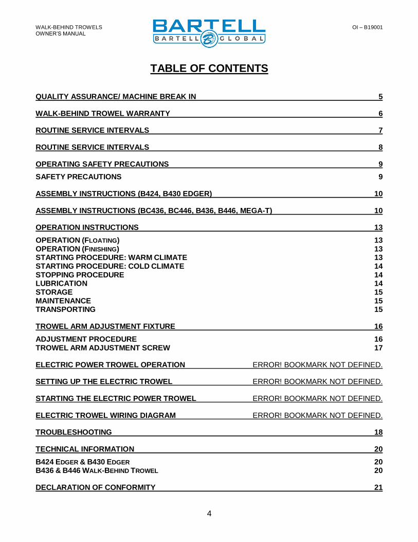
TABLE OF CONTENTS
QUALITY ASSURANCE/ MACHINE BREAK IN 5
WALK-BEHIND TROWEL WARRANTY 6
ROUTINE SERVICE INTERVALS 7
ROUTINE SERVICE INTERVALS 8
OPERATING SAFETY PRECAUTIONS 9
SAFETY PRECAUTIONS 9
ASSEMBLY INSTRUCTIONS (B424, B430 EDGER) 10
ASSEMBLY INSTRUCTIONS (BC436, BC446, B436, B446, MEGA-T) 10
OPERATION INSTRUCTIONS 13
OPERATION (FLOATING) 13 OPERATION (FINISHING) 13 STARTING PROCEDURE: WARM CLIMATE 13 STARTING PROCEDURE: COLD CLIMATE 14 STOPPING PROCEDURE 14 LUBRICATION 14 STORAGE 15 MAINTENANCE 15 TRANSPORTING 15
TROWEL ARM ADJUSTMENT FIXTURE 16
ADJUSTMENT PROCEDURE 16 TROWEL ARM ADJUSTMENT SCREW 17
ELECTRIC POWER TROWEL OPERATION ERROR! BOOKMARK NOT DEFINED.
SETTING UP THE ELECTRIC TROWEL ERROR! BOOKMARK NOT DEFINED.
STARTING THE ELECTRIC POWER TROWEL ERROR! BOOKMARK NOT DEFINED.
ELECTRIC TROWEL WIRING DIAGRAM ERROR! BOOKMARK NOT DEFINED.
TROUBLESHOOTING 18
TECHNICAL INFORMATION 20
B424 EDGER & B430 EDGER 20 B436 & B446 WALK-BEHIND TROWEL 20
DECLARATION OF CONFORMITY 21

WALK-BEHIND TROWELS OI – B19001
OWNER’S MANUAL
5
QUALITY ASSURANCE/ MACHINE BREAK IN
The Bartell Walk-Behind Power Trowel is the product of extensive engineering
development designed to give long life and unmatched performance. The Walk-Behind Power Trowels are Shipped Partially Assembled, and only require filling with fuel and a brief check of lubricant levels in preparation for operation.
You can help ensure that your Power Trowel will perform at top levels by observing a simple routing on first use. Consider that your new Power Trowel is like a new car. Just as you would break in a new car to the road or any new machine to the job, you should start gradually and build up to full use. Learn what your machine can do and how it will respond. Refer to the engine manufacturer’s manual for run-in times. Full throttle and control may be used after this time period, as allowed by material. This will serve to further break in the machine on your specific application, as well as provide you with additional practice using the machine.
We thank you for the confidence you have placed in us by purchasing a Bartell Walk-Behind Trowel and wish you many years of satisfied use.

WALK-BEHIND TROWELS OI – B19001
OWNER’S MANUAL
6
WALK-BEHIND TROWEL WARRANTY
All products sold by Bartell Morrison Inc. and Bartell Morrison (USA) LLC (the “Company”) are warranted against defects in materials and/or workmanship; excluding normal wear on wearing components and components covered by a separate original manufacturer’s warranty, for a period of 12 months (BC436, BC446) or 36 months (B424, B430, B436, B446, B446 Mega-T) from the date of sale to the original end user purchaser provided that certain conditions have been met. Conditions 1. The equipment serial number has been registered with the Company or its approved
dealers, distributors, representatives or agents. 2. The equipment has been operated in an appropriate manner by qualified individuals. 3. The equipment has been properly maintained as per the instructions included in the Owner’s
Manual. 4. All claims for warranty must be filed on proper forms and include the serial number of the
equipment along with proof of purchase. Any evidence of failure to meet these conditions may result in a denial of the warranty claim. Consideration of warranty claims will be at the sole discretion of the Company, or its authorized dealers, distributors, representatives or agents. The Company may, at its discretion, request that the equipment to be considered for warranty be returned at the owner’s expense to an authorized repair facility for inspection. Under this warranty we may, at our discretion, repair or replace a part or the whole of the defective component or equipment. Our Warranty coverage is limited to the cost to repair or replace the defective portion of the equipment and a reasonable (as determined by the Company) amount of labour to conduct the repair or replacement. Under no circumstances shall the Company be liable for any additional or exceptional costs beyond the cost to repair or replace the defective portion of the equipment. The Company shall not be held accountable for; costs associated with travel to inspect or repair defective equipment, costs for transporting defective equipment to or from an authorized repair facility, costs incurred to repair or replace the defective equipment at any facility other than one authorized by the Company or ancillary damage caused by or as a result of the defective equipment. Under no circumstances shall equipment be returned to the Company or its authorized dealers, distributors, representatives or agents without the approval of the Company as evidenced by a Returned Goods Number. To obtain a Returned Goods Number contact the factory or your authorized dealer, distributor, representative or agent. This warranty is for the sole benefit of the original end user purchaser and is not transferable to any other company or person.
WALK-BEHIND TROWELS OI – B19001
OWNER’S MANUAL
7
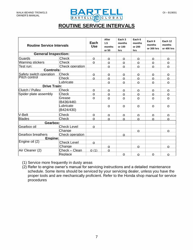
ROUTINE SERVICE INTERVALS
Routine Service Intervals Each Use
After
1.5
months
or 50
hrs
Each 3
months
or 100
hrs
Each 6
months
or 200
hrs
Each 9
months
or 300 hrs
Each 12
months
or 400 hrs
General Inspection: Guards Check o o o o o o Warning stickers Check o o o o o o Test run: Check operation o o o o o
Controls: Safety switch operation Check o o o o o o Pitch control Check o o o o o o
Lubricate o o o o o Drive Train:
Clutch / Pulley operation
Check o o o o o o Spider plate assembly Check o o o o o o
Grease (B436/446)
o o o o o o
Lubricate (B424/430)
o o o o o
V-Belt Check o o o o o o Blades Check o o o o o o
Gearbox: Gearbox oil Check Level o
Change o o Gearbox breathers Check operation o
Engine: Engine oil (2) Check Level o
Change o o o Air Cleaner (2) Check – Clean
(1) o (1) o
Replace o o o o
(1) Service more frequently in dusty areas (2) Refer to engine owner’s manual for servicing instructions and a detailed maintenance
schedule. Some items should be serviced by your servicing dealer, unless you have the proper tools and are mechanically proficient. Refer to the Honda shop manual for service procedures

WALK-BEHIND TROWELS OI – B19001
OWNER’S MANUAL
8
ROUTINE SERVICE INTERVALS Due to the nature and environment of use, Power Trowels could be exposed to severe operating conditions. Some general maintenance guidelines will extend the useful life of your trowel.
• The initial service for your power trowel should be performed after 25 hours of use, at which time your mechanic (or authorized repair shop) should complete all of the recommended checks in the schedule above.
• Regular service according to the schedule above will prolong the life of the Power Trowel and prevent expensive repairs.
• Keeping your Power Trowel clean and free from debris is the single most important regular maintenance operation, over and above the checks in the service schedule above, that can be performed. After each use your Power Trowel should be cleaned to remove any dust and debris from the undercarriage and surrounding components. Use of a power washer will make clean up quick and easy, especially if a non-stick coating was applied prior to use.
• In the Service Schedule above, items that should be checked, replaced or adjusted are indicated by “o” in the appropriate column. Not all Power Trowel models include the same features and options and as such not all service operations may have to be
performed. For ease of recording place a checkmark (√) through the “o” when the item
is complete. If an item is not required or not completed place an “x” through the “o” in the box.
• All Power Trowels have governed engine speed of 3600 rpm. See engine manufacturer’s manual for exact specifications. Care should be used when making any adjustments to the Power Trowel not to change the governed speed.
• Failure to have your Power Trowel regularly serviced and properly maintained in accordance with the manufacturer’s instructions will lead to premature failure and void the warranty.

WALK-BEHIND TROWELS OI – B19001
OWNER’S MANUAL
9
OPERATING SAFETY PRECAUTIONS
SAFETY PRECAUTIONS
• Always keep unauthorized, inexperienced, untrained people away from this machine.
• Rotating and moving parts will cause injury if contacted. Make sure guards are in place. Keep hands and feet away from moving parts.
• Fuel the machine only when the engine is stopped, using all necessary safety precautions.
• The engine must always be stopped before attempting any repair or adjustments. Ignition switch should be off.
• Be careful when working around pipes or ducts protruding from the floor or slab edges. If the trowel blades hit such obstacles, damage to the machine or possible operator injury may result.
• When starting the machine, do not exceed 1/3 throttle position. A higher setting may cause the centrifugal clutch to engage and the handle to rotate.
• Be careful not to come in contact with the muffler when the engine is hot, serious burns may result!
• Over time, the blades will form a sharp edge. Be careful when handling the old blades.
DANGER: Never operate the machine in an explosive atmosphere, near combustible materials or where ventilation does not clear exhaust fumes. Repair fuel leaks immediately. Refer to your engine owner’s manual for more safety instructions.
WALK-BEHIND TROWELS OI – B19001
OWNER’S MANUAL
10
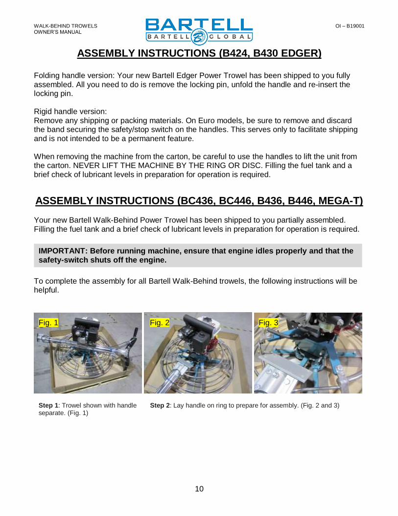
ASSEMBLY INSTRUCTIONS (B424, B430 EDGER)
Folding handle version: Your new Bartell Edger Power Trowel has been shipped to you fully assembled. All you need to do is remove the locking pin, unfold the handle and re-insert the locking pin. Rigid handle version: Remove any shipping or packing materials. On Euro models, be sure to remove and discard the band securing the safety/stop switch on the handles. This serves only to facilitate shipping and is not intended to be a permanent feature. When removing the machine from the carton, be careful to use the handles to lift the unit from the carton. NEVER LIFT THE MACHINE BY THE RING OR DISC. Filling the fuel tank and a brief check of lubricant levels in preparation for operation is required.
ASSEMBLY INSTRUCTIONS (BC436, BC446, B436, B446, MEGA-T)
Your new Bartell Walk-Behind Power Trowel has been shipped to you partially assembled. Filling the fuel tank and a brief check of lubricant levels in preparation for operation is required.
To complete the assembly for all Bartell Walk-Behind trowels, the following instructions will be helpful.
IMPORTANT: Before running machine, ensure that engine idles properly and that the safety-switch shuts off the engine.
Step 1: Trowel shown with handle separate. (Fig. 1)
Step 2: Lay handle on ring to prepare for assembly. (Fig. 2 and 3)
Fig. 1 Fig. 3 Fig. 2

WALK-BEHIND TROWELS OI – B19001
OWNER’S MANUAL
11
Step 3: Install pitch control cable to yoke and install locknut loosely (Fig. 4). If needed, turn pitch control knob counter-clockwise until the stop screw is at the lowest position (Fig. 5).
Step 4: Lift and install handle to position using the supplied four sets of lockwashers and nuts. Do not torque greater than 18ft-lb. At the yoke; tighten the locknut for pitch control cable (Fig. 6). If the cable is too loose or tight, the pitch control range position can be moved by changing the position of the stop screw (Fig. 5). The factory default is the middle position. Turn the pitch control knob completely clockwise and check for maximum pitch possible. This is possible when the clearance between the yoke and underside of the gearbox is enough to pass a business card through.
Step 5: Unwrap throttle control and engine safety shut-off wires to prepare for their assembly. (Fig. 7 and 8)
Step 6: Remove air filter cover and air filter. (Fig. 9)
Step 7: Check for free moving engine throttle control lever and loosen pivot nut if necessary (Fig. 10)
Step 8: Push handle throttle lever all the way forward for idle position (Fig. 11). If necessary, the tension screw can be adjusted for smooth operation while holding throttle position.
Step 9: Install the throttle control wire into the throttle control lever. (Fig. 12)
Fig. 4 Fig. 5 Fig. 6
Fig. 7 Fig. 8 Fig. 9
Fig. 10 Fig. 11 Fig. 12
WALK-BEHIND TROWELS OI – B19001
OWNER’S MANUAL
12
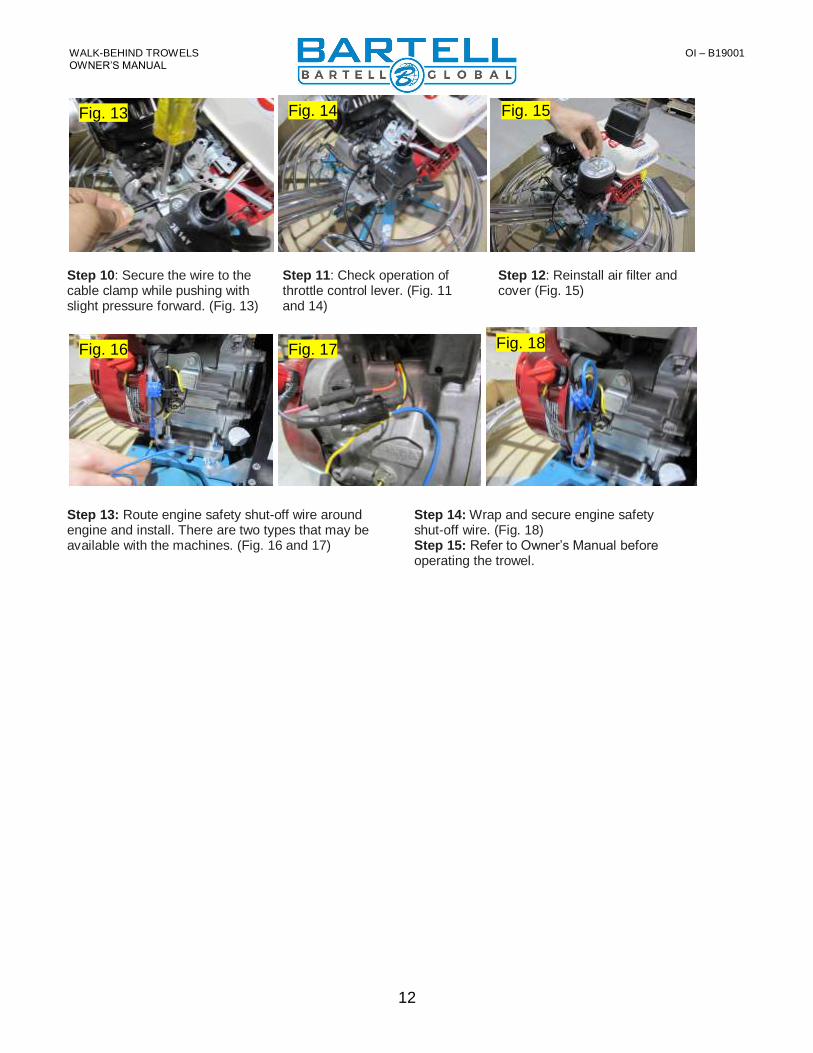
Step 10: Secure the wire to the cable clamp while pushing with slight pressure forward. (Fig. 13)
Step 11: Check operation of throttle control lever. (Fig. 11 and 14)
Step 12: Reinstall air filter and cover (Fig. 15)
Step 13: Route engine safety shut-off wire around engine and install. There are two types that may be available with the machines. (Fig. 16 and 17)
Step 14: Wrap and secure engine safety shut-off wire. (Fig. 18) Step 15: Refer to Owner’s Manual before operating the trowel.
Fig. 13 Fig. 14 Fig. 15
Fig. 16 Fig. 17 Fig. 18
WALK-BEHIND TROWELS OI – B19001
OWNER’S MANUAL
13
OPERATION INSTRUCTIONS
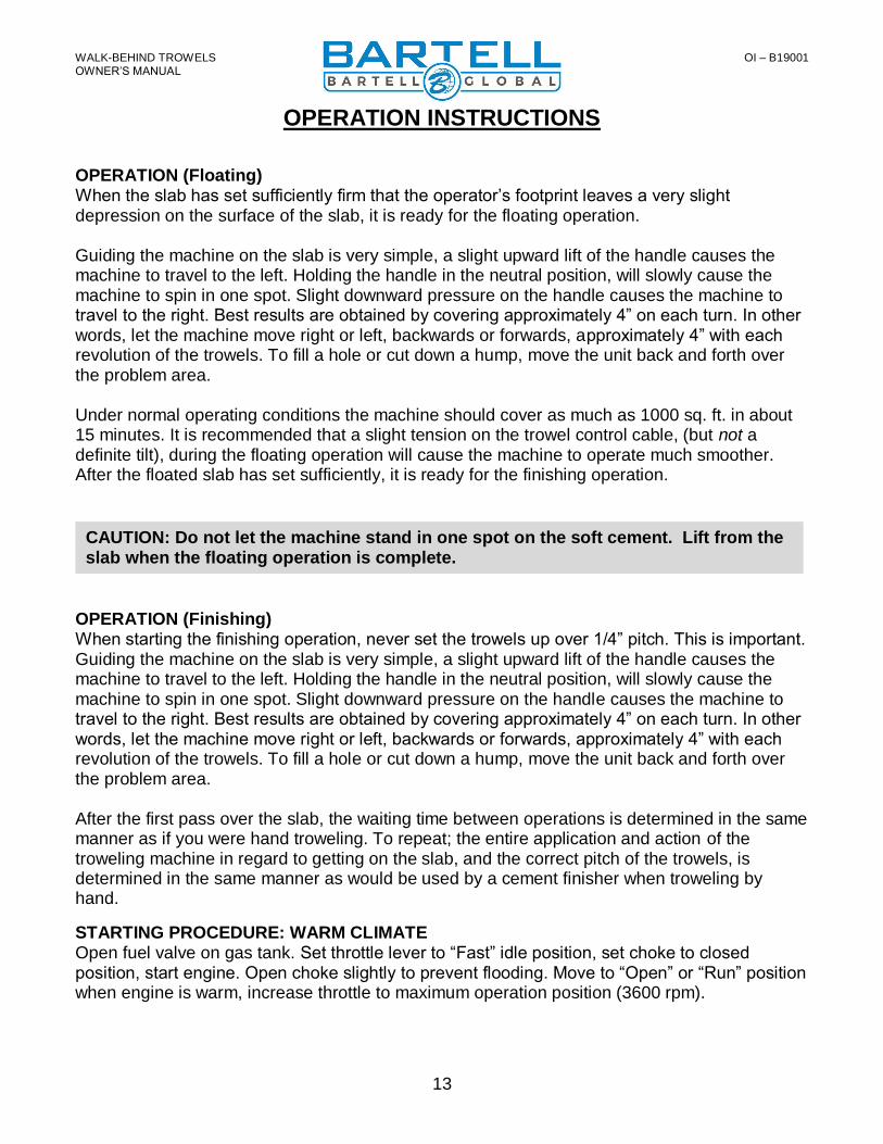
OPERATION (Floating) When the slab has set sufficiently firm that the operator’s footprint leaves a very slight depression on the surface of the slab, it is ready for the floating operation. Guiding the machine on the slab is very simple, a slight upward lift of the handle causes the machine to travel to the left. Holding the handle in the neutral position, will slowly cause the machine to spin in one spot. Slight downward pressure on the handle causes the machine to travel to the right. Best results are obtained by covering approximately 4” on each turn. In other words, let the machine move right or left, backwards or forwards, approximately 4” with each revolution of the trowels. To fill a hole or cut down a hump, move the unit back and forth over the problem area. Under normal operating conditions the machine should cover as much as 1000 sq. ft. in about 15 minutes. It is recommended that a slight tension on the trowel control cable, (but not a definite tilt), during the floating operation will cause the machine to operate much smoother. After the floated slab has set sufficiently, it is ready for the finishing operation.
OPERATION (Finishing) When starting the finishing operation, never set the trowels up over 1/4” pitch. This is important. Guiding the machine on the slab is very simple, a slight upward lift of the handle causes the machine to travel to the left. Holding the handle in the neutral position, will slowly cause the machine to spin in one spot. Slight downward pressure on the handle causes the machine to travel to the right. Best results are obtained by covering approximately 4” on each turn. In other words, let the machine move right or left, backwards or forwards, approximately 4” with each revolution of the trowels. To fill a hole or cut down a hump, move the unit back and forth over the problem area. After the first pass over the slab, the waiting time between operations is determined in the same manner as if you were hand troweling. To repeat; the entire application and action of the troweling machine in regard to getting on the slab, and the correct pitch of the trowels, is determined in the same manner as would be used by a cement finisher when troweling by hand.
STARTING PROCEDURE: WARM CLIMATE Open fuel valve on gas tank. Set throttle lever to “Fast” idle position, set choke to closed position, start engine. Open choke slightly to prevent flooding. Move to “Open” or “Run” position when engine is warm, increase throttle to maximum operation position (3600 rpm).
CAUTION: Do not let the machine stand in one spot on the soft cement. Lift from the slab when the floating operation is complete.

WALK-BEHIND TROWELS OI – B19001
OWNER’S MANUAL
14
STARTING PROCEDURE: COLD CLIMATE Follow same procedure as above but allow longer warm-up period – 3 to 5 minutes. In cold weather, oil is much heavier to move and requires more time to work its way into the moving parts. If maximum power is not attained, allow further warm-up time. Fill fuel tank with clean gasoline, use safety approved gas containers. DO NOT MIX OIL WITH GASOLINE – USE UNLEADED GAS ONLY.
STOPPING PROCEDURE
1. Throttle engine down 2. Turn off stop switch
LUBRICATION 1. ENGINE OIL
The long life and successful operation of any piece of machinery is dependent on frequent and thorough lubrication. Before using the trowel, always check your engine for oil. Use proper engine oil as recommended in the engine manufacturer’s manual. Fill crankcase to levels as recommended.
2. SPIDER PLATE - GREASE There are 4 (four) grease fittings on the spider plate, each must be greased daily. THE SPIDER PLATE MUST BE GREASED EVERY TIME MACHINE IS USED.
3. SPIDER PLATE – OIL BATH (B424/B430 Edger only) The trowel arm on the spider plate does not require lubrication to be added every use. However, the oil in the oil bath spider plate should be checked periodically and topped up or changed if necessary.
4. HOW TO CHANGE OIL IN THE OIL BATH SPIDER PLATE (B424/B430 Edger only) Step 1. First remove the set screw that holds the trowel arm into the spider plate Step 2. Add oil through the set screw hole. Very little oil is needed. Step 3. While rotating the trowel arm throughout its pitch direction, pull the trowel arm about half to three quarters of the way out of the spider plate. This should be done about half dozen times. Doing this releases any pressure that may have built up in the chamber that holds the arm and the oil. The pressure will release through the oil grooves and through the vacant bolt hole. Add oil if necessary. Step 4. Push the trowel arm back into its proper location and re-install the set screw. The trowel arm should move freely. Step 5. Steps 1 to 4 should be repeated for remaining trowel arms.
5. GEARBOX (Except B424/B430 Edger)
Check the oil level sight plug on the gearbox daily to ensure the oil is half way on the site glass. Top up with Agma 8 compounded gear oil only. Gearbox capacity 16 oz. to 19 oz. (473ml. To 562ml.) Example: Esso/Exxon Cylesstic TK680.
6. TO CHANGE GEARBOX OIL (Except B424/B430 Edger) Place a pan beneath the drain plug to catch the oil. Remove the drain plug and the filler
NOTE: THE LUBRICATION SYSTEM SHOULD BE CHECKED AT LEAST ONCE PER MONTH TO ENSURE THAT THE UNIT IS FUNCTIONING PROPERLY.
ENGINE OIL SPECIFICATIONS All seasons: SAE 10W-30
WALK-BEHIND TROWELS OI – B19001
OWNER’S MANUAL
15
plug from the gearbox. After the oil has drained completely, replace the drain plug and tighten. Fill gearbox through the filler plug with 16 oz. to 19 oz. (473ml to 526ml) of Agma 8 compound gear oil. Replace the filler and tighten.
7. GEARBOX (B424/B430 Edger) Check for oil leaks around gearbox. If necessary, remove drain plug from back of gearbox to drain and refill with 10.1 oz. (0.3 L) of Shell Tivela Compound A or similar.
STORAGE The following steps should be taken to prepare your walk-behind trowel for extended storage.
1. Clean the exterior surfaces of the trowel. 2. Close fuel shut off valve. 3. Siphon excess gasoline from tank. 4. Start engine until it stops from lack of fuel. This will use up all the fuel in the carburetor
and prevent formation of deposits due to evaporation of fuel. 5. Store the unit in an upright position in a cool, dry, well ventilated area. 6. Refer to the engine manual for more information.
MAINTENANCE Maintaining your Walk-Behind Power Trowel will insure long life to the machine and its components.
AIR CLEANER - Keep air filter clean at all times. Refer to engine manual. LUBRICATION – Check engine oil regularly. Use proper engine oil as recommended. See previous chart. Fill crankcase to levels as recommended in manufacture’s engine manual. SPARK PLUG – Check and clean spark plugs regularly. A fouled or dirty spark plug causes hard starting and poor engine performance. Set spark plug gap to recommended clearance. Refer to engine manual. BELT TENSION – IMPORTANT! When the engine is switched off, and the machine has stopped, the normal belt play should be loose. This is due to the clutch type. When the machine is running at full throttle, the clutch will close in, which tightens the belt causing the gearbox to engage. When adjusting the belt make sure that the clutch is in alignment with the follower pulley. Secure belt guard. Tighten all engine mount bolts, and tighten lock nuts.
TRANSPORTING – When transporting the trowel, always keep the handle folded (if equipped) and the blades flat on the floor to prevent damage to the pitch control system. Always keep the floating disc (if equipped) underneath the blades to protect them against damage.
EDGER TROWEL CAUTION: Never lift the trowel by the rotating ring; use the hoist hook or handle provided on the trowel. Remove the float disc when lifting machine more than 100cm (40”). The floating disc could fall off.
WALK-BEHIND TROWELS OI – B19001
OWNER’S MANUAL
16
TROWEL ARM ADJUSTMENT FIXTURE
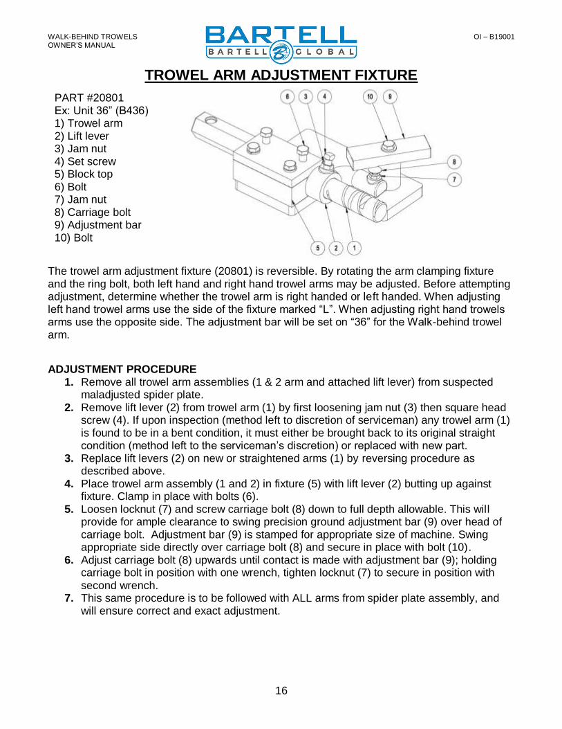
The trowel arm adjustment fixture (20801) is reversible. By rotating the arm clamping fixture and the ring bolt, both left hand and right hand trowel arms may be adjusted. Before attempting adjustment, determine whether the trowel arm is right handed or left handed. When adjusting left hand trowel arms use the side of the fixture marked “L”. When adjusting right hand trowels arms use the opposite side. The adjustment bar will be set on “36” for the Walk-behind trowel arm.
ADJUSTMENT PROCEDURE 1. Remove all trowel arm assemblies (1 & 2 arm and attached lift lever) from suspected
maladjusted spider plate. 2. Remove lift lever (2) from trowel arm (1) by first loosening jam nut (3) then square head
screw (4). If upon inspection (method left to discretion of serviceman) any trowel arm (1) is found to be in a bent condition, it must either be brought back to its original straight condition (method left to the serviceman’s discretion) or replaced with new part.
3. Replace lift levers (2) on new or straightened arms (1) by reversing procedure as described above.
4. Place trowel arm assembly (1 and 2) in fixture (5) with lift lever (2) butting up against fixture. Clamp in place with bolts (6).
5. Loosen locknut (7) and screw carriage bolt (8) down to full depth allowable. This will provide for ample clearance to swing precision ground adjustment bar (9) over head of carriage bolt. Adjustment bar (9) is stamped for appropriate size of machine. Swing appropriate side directly over carriage bolt (8) and secure in place with bolt (10).
6. Adjust carriage bolt (8) upwards until contact is made with adjustment bar (9); holding carriage bolt in position with one wrench, tighten locknut (7) to secure in position with second wrench.
7. This same procedure is to be followed with ALL arms from spider plate assembly, and will ensure correct and exact adjustment.
PART #20801 Ex: Unit 36” (B436) 1) Trowel arm 2) Lift lever 3) Jam nut 4) Set screw 5) Block top 6) Bolt 7) Jam nut 8) Carriage bolt 9) Adjustment bar 10) Bolt

WALK-BEHIND TROWELS OI – B19001
OWNER’S MANUAL
17
TROWEL ARM ADJUSTMENT SCREW The trowel arm adjustment screw is to be used for field adjustment of blade level, in the event of a damaged trowel arm, to enable completion of the job. At the end of the job repairs should be made to eliminate the damage. When assembling trowel blades to trowel arms, the adjustment screw should NEVER protrude below the under-side surface of a trowel arm. If the adjustment screw is not flush with the underside of the trowel arm, then this will cause the power trowel to bounce and vibrate especially at high speed. This will also cause the trowel blades to leave an uneven finish to the concrete due to the blades not being level to one another. Make certain that the adjusting screw is held firmly in place while tightening the bolt which secures the blade to the trowel arm.

WALK-BEHIND TROWELS OI – B19001
OWNER’S MANUAL
18
TROUBLESHOOTING
WON’T START - Throttle fully open - Hand lever wire broken - No gas - Dirty gas - Gas filter plugged - Gas line plugged - Hole in gas line - Gas supply valve turned off - Dead-man safety switch - Safety switch wire or connectors not making good
contact - Other engine problems (Refer to engine manual)
STARTS BUT NO HIGH SPEED
- Engine problems - Throttle cable broken or seized - Throttle lever and connectors loose or out of
adjustment - Clutch shoes worn
STARTS AT HIGH SPEED, WON’T SLOW DOWN
- Same as above ENGINE WON’T STOP
- Safety switch, wire or connectors not making good contact
ENGINE STARTS BUT WON’T TURN TROWELS AT ANY SPEED
- Clutch seized - No weights or broken clutch - Wrong belt - Broken or missing key
o Clutch o Pulley o Worm gear (countershaft) o Main gear o Spider plate
- Gearbox seized TROWELS TURN, ENGINE AT IDLE
- Idle too fast - Belt too tight - Clutch seized - Pulley out of alignment
TROWELS BLADES WEARING UNEVENLY - Spider plate seized - Arms bent - Adjusting screws (carriage bolts) incorrectly set
MACHINE JUMPS ON FLOOR
- Concrete hardened on bottom of spider plate - Trowels unevenly worn - Spider plate seized - Spider plate loose - Trowel arms bent - Adjusting screws (carriage bolts) incorrectly set use
spider plate adjustment jig (pg,13) - Mainshaft bent
PITCH CONTROLS WILL NOT OPERATE BLADES
- Cable broken or out of adjustment - Slot screw missing (under-side of handle) - Spider plate seized - Pressure plate and/or yoke arm broken or badly
worn - Hand crank adjuster malfunctioning
BELT WEARING RAPIDLY
- Belt adjusted improperly - Pulley out of alignment - Wrong belt/defective belt - Clutch sticking - Gearbox seizing
OIL LEAKS
- Top of gearbox o Engine leaks o Relief valve broken o Too much oil in gearbox o Set screw missing in cover
- Between end cap and gearbox (recoil side) o “O” ring damaged o End cap not tight
- At mainshaft or countershaft o Relief valve seized o Shaft and/or seal worn
TROWEL BLADES WILL NOT TURN
- Yoke arm broken - Key sheared
SPIDER PLATE HARD TO GREASE
- Fittings plugged - Cement in grease grooves of arms - Grease fittings too tight

WALK-BEHIND TROWELS OI – B19001
OWNER’S MANUAL
19
SPECIFICATIONS
Model Path Power Source (gas option)
Float Blade Size
Finish Blade Size
Combination Blade Size
Float Pan
Operating Weight
B424 (Edger)
24” (60cm)
Honda GX160 N/A 4.75” x 9” (12cm x 23cm)
N/A 24” (60cm)
Up to 110lbs (50kg)
B430 (Edger)
30” (76cm)
Honda GX160 10” x 30” (25cm x 28cm)
6” x 10.5” (15cm x 26cm)
6” x 10” (15cm x 25cm)
30” (76cm)
Up to 145lbs (66kg)
BC436 36” (91cm)
Honda GX160 Honda GX270
10” x 14” (25cm x 36cm)
6” x 14” (15cm x 36cm)
8” x 14” (20cm x 36cm)
38.5” (98cm)
Up to 195lbs (88kg)
BC446 46” (120cm)
Honda GX270 Honda GX340 Honda GX390
10” x 18” (25cm x 46cm)
6” x 18” (15cm x 46cm)
8” x 18” (20cm x 46cm)
48.5” (123cm)
Up to 255lbs (115kg)
B436 36” (91cm)
Honda GX160 Honda GX270
10” x 14” (25cm x 36cm)
6” x 14” (15cm x 36cm)
8” x 14” (20cm x 36cm)
38.5” (98cm)
Up to 195lbs (88kg)
B446 46” (120cm)
Honda GX270 Honda GX340 Honda GX390
10” x 18” (25cm x 46cm)
6” x 18” (15cm x 46cm)
8” x 18” (20cm x 46cm)
48.5” (123cm)
Up to 255lbs (115kg)
Mega-T B446
46” (120cm)
Honda GX340 Honda GX390
10” x 18” (25cm x 46cm)
6” x 18” (15cm x 46cm)
8” x 18” (20cm x 46cm)
48.5” (123cm)
Up to 285lbs (129kg)
WALK-BEHIND TROWELS OI – B19001
OWNER’S MANUAL
20
Centrifugal Yes
TECHNICAL INFORMATION
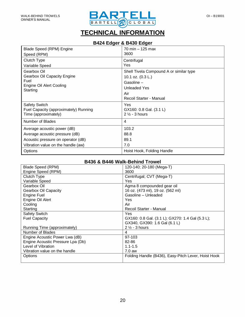
B424 Edger & B430 Edger
Blade Speed (RPM) Engine
Speed (RPM)
70 min – 125 max
3600
Clutch Type
Variable Speed
Gearbox Oil
Gearbox Oil Capacity Engine Fuel Engine Oil Alert Cooling Starting
Shell Tivela Compound A or similar type
10.1 oz. (0.3 L.)
Gasoline –
Unleaded Yes
Air
Recoil Starter - Manual
Safety Switch
Fuel Capacity (approximately) Running Time (approximately)
Yes
GX160: 0.8 Gal. (3.1 L) 2 ½ - 3 hours
Number of Blades 4
Average acoustic power (dB) 103.2
Average acoustic pressure (dB) 88.8
Acoustic pressure on operator (dB) 89.1
Vibration value on the handle (aw) 7.0
Options Hoist Hook, Folding Handle
B436 & B446 Walk-Behind Trowel Blade Speed (RPM) Engine Speed (RPM)
120-140; 20-180 (Mega-T) 3600
Clutch Type Variable Speed
Centrifugal; CVT (Mega-T) Yes
Gearbox Oil Gearbox Oil Capacity Engine Fuel Engine Oil Alert Cooling Starting
Agma 8 compounded gear oil 16 oz. (473 ml), 19 oz. (562 ml) Gasoline – Unleaded Yes Air Recoil Starter - Manual
Safety Switch Fuel Capacity Running Time (approximately)
Yes GX160: 0.8 Gal. (3.1 L); GX270: 1.4 Gal (5.3 L); GX340, GX390: 1.6 Gal (6.1 L) 2 ½ - 3 hours
Number of Blades 4
Engine Acoustic Power Lwa (dB) Engine Acoustic Pressure Lpa (Db) Level of Vibration Vibration value on the handle
97-103 82-86 1.1-1.5 7.0 aw
Options
Folding Handle (B436), Easy-Pitch Lever, Hoist Hook
WALK-BEHIND TROWELS OI – B19001
OWNER’S MANUAL
21
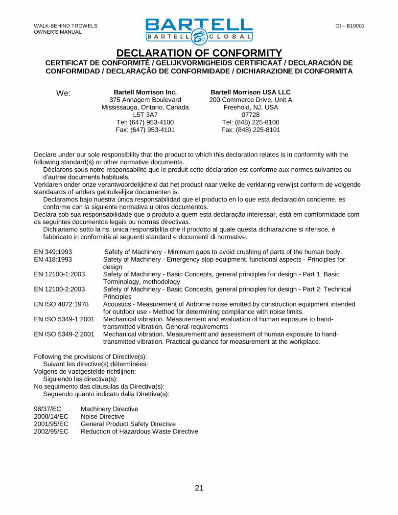
DECLARATION OF CONFORMITY CERTIFICAT DE CONFORMITÉ / GELIJKVORMIGHEIDS CERTIFICAAT / DECLARACIÓN DE CONFORMIDAD / DECLARAÇÃO DE CONFORMIDADE / DICHIARAZIONE DI CONFORMITA
Declare under our sole responsibility that the product to which this declaration relates is in conformity with the following standard(s) or other normative documents.
Déclarons sous notre responsabilité que le produit cette déclaration est conforme aux normes suivantes ou d’autres documents habituels.
Verklaren onder onze verantwoordelijkheid dat het product naar welke de verklaring verwijst conform de volgende standaards of anders gebruikelijke documenten is.
Declaramos bajo nuestra única responsabilidad que el producto en lo que esta declaración concierne, es conforme con la siguiente normativa u otros documentos.
Declara sob sua responsabilidade que o produto a quem esta declaração interessar, está em comformidade com os seguintes documentos legais ou normas directivas.
Dichiariamo sotto la ns. unica responsibilita che il prodotto al quale questa dichiarazione si riferisce, è fabbricato in conformità ai seguenti standard e documenti di normative.
EN 349:1993 Safety of Machinery - Minimum gaps to avoid crushing of parts of the human body. EN 418:1993 Safety of Machinery - Emergency stop equipment, functional aspects - Principles for
design EN 12100-1:2003 Safety of Machinery - Basic Concepts, general principles for design - Part 1: Basic
Terminology, methodology EN 12100-2:2003 Safety of Machinery - Basic Concepts, general principles for design - Part 2: Technical
Principles EN ISO 4872:1978 Acoustics - Measurement of Airborne noise emitted by construction equipment intended
for outdoor use - Method for determining compliance with noise limits. EN ISO 5349-1:2001 Mechanical vibration. Measurement and evaluation of human exposure to hand-
transmitted vibration. General requirements EN ISO 5349-2:2001 Mechanical vibration. Measurement and assessment of human exposure to hand-
transmitted vibration. Practical guidance for measurement at the workplace. Following the provisions of Directive(s):
Suivant les directive(s) déterminées: Volgens de vastgestelde richtlijnen:
Siguiendo las directiva(s): No sequimento das clausulas da Directiva(s):
Seguendo quanto indicato dalla Direttiva(s): 98/37/EC Machinery Directive 2000/14/EC Noise Directive 2001/95/EC General Product Safety Directive 2002/95/EC Reduction of Hazardous Waste Directive
Bartell Morrison Inc. 375 Annagem Boulevard
Mississauga, Ontario, Canada L5T 3A7
Tel: (647) 953-4100 Fax: (647) 953-4101
Bartell Morrison USA LLC 200 Commerce Drive, Unit A
Freehold, NJ, USA 07728
Tel: (848) 225-8100 Fax: (848) 225-8101
We:

WALK-BEHIND TROWELS OI – B19001
OWNER’S MANUAL
22
This Page Intentionally Left Blank

www.BARTELLGLOBAL.com
Bartell Morrison Inc.
375 Annagem Boulevard Mississauga, Ontario, Canada
L5T 3A7 Tel: 1-647-953-4100 Fax: 1-647-953-4101
Bartell Morrison (USA) LLC
200 Commerce Drive, Unit A Freehold, New Jersey, USA
07728 Tel: 1-848-225-8100 Fax: 1-848-225-8101
Innovatech
4701 Allmond Ave Louisville, Kentucky, USA
40209 Tel: 1-425-405-9100 Fax: 1-425-405-9101
SPE International Honeyholes Lane
Dunholme, Lincoln, UK LN2 3SU
Tel: +44 (0)1673 860709 Fax: +44 (0)1673 861119


