VOLUME – I TECHNICAL OPERATION AND MAINTENANCE REQUIREMENTS FOR RURAL PIPED SYSTEM PART - A INTRODUCTION PART- B WATER SOURCES FOR WATER SUPPLY PART – C ELECTRO-MECHANICAL EQUIPMENT PART – D TRANSMISSION AND DISTRIBUTION SYSTEM PART – E SPARE PARTS SUPPLY AND MANAGEMENT PART – F EQUIPMENT AND TOOLS MANAGEMENT MANUAL PART – G LEAKAGE DETECTION AND CONTROL PART – H FIXED ASSET INVENTORY PART – I WATER QUALITY MONITORING AND SURVELLIANCE
Transcript
VOLUME – I TECHNICAL OPERATION AND MAINTENANCE REQUIREMENTS FOR RURAL PIPED SYSTEM
PART - A INTRODUCTION
PART- B WATER SOURCES FOR WATER SUPPLY
PART – C ELECTRO-MECHANICAL EQUIPMENT
PART – D TRANSMISSION AND DISTRIBUTION SYSTEM
PART – E SPARE PARTS SUPPLY AND MANAGEMENT
PART – F EQUIPMENT AND TOOLS MANAGEMENT MANUAL
PART – G LEAKAGE DETECTION AND CONTROL
PART – H FIXED ASSET INVENTORY
PART – I WATER QUALITY MONITORING AND SURVELLIANCE
Ministry of Water, Irrigation and Electricity
Technical Operation and Maintenance Requirements Manual for Rural Piped
System
DEMEWOZ CONSULTANCY
Vol-I, Part-B: Page -i
Technical Operation and Maintenance Requirements Manual for Rural Piped System: VOLUME-I, PART – B: WATER SOURCES FOR WATER SUPPLY
Table of Contents
List of Tables ii List of Figures ii List of Annexes iii
2. WATER SOURCES FOR WATER SUPPLY 1
2.1 General 1
2.2 Objective of O&M for Water Sources 1
2.3 Water Sources 2
2.3.1 Groundwater 2 2.3.2 Surface Water 2 2.3.3 Rainwater 2
2.4 Sources of Water Supply Facilities 2
2.5 Operation and Maintenance Requirements 3
2.5.1 Wells and Boreholes 3 2.5.1.1 Component of Borehole 3 2.5.1.2 Causes of Failure of Wells 4 2.5.1.3 Well Operation 4 2.5.1.4 Water level and Drawdown 5 2.5.1.5 Borehole Sounding 6 2.5.1.6 Well Yield 6 2.5.1.7 Specific Capacity 7 2.5.1.8 Well Maintenance 7 2.5.1.9 O&M Schedule for Deep Borehole 8 2.5.1.10 O&M Resources for Motorized Borehole 9 2.5.1.11 Rehabilitation of Boreholes 9 2.5.1.12 Incrustation 11 2.5.1.13 Rehabilitation of Incrusted Boreholes 13 2.5.1.14 Inadequate Development 19 2.5.1.15 Prevention of Incrustation and Corrosion 21 2.5.1.16 Prevention of Corrosion 22 2.5.1.17 Artificial Recharge of Groundwater 23 2.5.1.18 Conservation of Groundwater 23
2.5.2 Infiltration Well and their Maintenance 24 2.5.3 Infiltration Gallery 24
2.5.3.1 Sanitary Inspection of Infiltration Gallery 25 2.5.3.2 Maintenance of Infiltration Gallery 25
2.5.4 Spring Collection Chamber 26 2.5.4.1 General 26 2.5.4.2 Components of Spring Chamber 26 2.5.4.3 Operation and Maintenance Requirements 27
2.5.5 River and Lake Intakes 30 2.5.5.1 General 30 2.5.5.2 Intake Components 30 2.5.5.3 Intake Specific O & M tasks 31 2.5.5.4 Troubleshooting for River Intake 31
Ministry of Water, Irrigation and Electricity
Technical Operation and Maintenance Requirements Manual for Rural Piped
System
DEMEWOZ CONSULTANCY
Vol-I, Part-B: Page -ii
2.5.5.5 Problems in Operation 32 2.5.5.6 Operation and Maintenance 32 2.5.5.7 Record Keeping 33 2.5.5.8 Safety 33
2.5.6 Impounding Reservoirs 33 2.5.6.1 Catchment Area Maintenance 34 2.5.6.2 Trouble shooting for Impounding Reservoir 35 2.5.6.3 Types of Dams 36 2.5.6.4 Inspection of Dams 36
2.7.1 General 40 2.7.2 Water source problems 41 2.7.3 Environmental factors affecting drinking water sources 41
2.7.3.1 Contamination by pesticides and fertilizers 41 2.7.3.2 Over-extraction of Groundwater 42 2.7.3.3 Land use changes in large source catchment area 42
2.7.4 Measures for minimizing water source problems 42 2.7.4.1 Risk assessment 42
Annexes 46
List of Tables
Table 2-1: Components of Borehole 3 Table 2-2: Solubility of Sulphamic Acid in Water 16 Table 2-3: Submergence Requirements of the Airline 20 Table 2-4: Summary of O&M Requirement for Spring Protection 28 Table 2-5: Troubleshooting for Spring Intake 29 Table 2-7: Troubleshooting for River Intake with Weir or Sump 31 Table 2-8: Components of Impounding Reservoir 34 Table 2-9: Trouble Shooting for Impounding Reservoir 35 Table 2-10: Preventive Maintenance Checklist for Water Sources Facilities 39 Table 2-11: Defining Water Source Problems 41 Table 2-12: Faecal Contamination Grading 44
List of Figures
Figure 2-1: Airline Installed in Borehole for measuring water level 6 Figure 2-2: Impression Block 11 Figure 2-3: Set up of Acid Treatment 14 Figure 2-4: Cathodic Protecting Arrangement for Boreholes 23 Figure 2-5: Schematic Section of Spring Development with Spring Box 26 Figure 2-6: Schematic Plan of Spring Development with Spring Box 26 Figure 2-7: Typical Spring Intake 29 Figure 2-8: Typical River Intake with Weir Wall and Sump 32 Figure 2-9: Typical Embankment Dam 34
List of Boxes
Ministry of Water, Irrigation and Electricity
Technical Operation and Maintenance Requirements Manual for Rural Piped
System
DEMEWOZ CONSULTANCY
Vol-I, Part-B: Page -iii
Box 1: O&M Objectives at Water Sources 1 Box 2: Daily O&M Activities for Boreholes 8 Box 3: Lists of Spring Box, Reservoir and Public Water point Inspection 27 Box 4: O&M tasks for Catchment area 35
List of Annexes
Annex A: Monthly Check sheet for spring Type-1 46 Annex B: Monthly Check sheet for spring Type-2 47 Annex C: Daily Water Production Record 48 Annex D: Daily Water Distribution Record 49
Ministry of Water, Irrigation and Electricity
Technical Operation and Maintenance Requirements Manual for Rural Piped
System
DEMEWOZ CONSULTANCY
Vol-I, Part-B: Page -1
2. WATER SOURCES FOR WATER SUPPLY
2.1 General
This Chapter covers the basic concepts and procedures for proper operation and maintenance of water sources and the equipment used at these sources to prepare the water for distribution.
It covers the operation, maintenance and rehabilitation required for wells, infiltration gallery, rive intakes, impounding reservoir of the sources for water supply.
A properly designed and constructed well can give many years of trouble-free service.
Good O&M seeks to avert well failures, which are usually indicated by reduced (if not, complete loss of) pump discharge or deterioration in the quality of the water.
Good O&M actually begins even before a well is put into operation. Before actually operating a well, it must be determined /obtained the following information which will guide its well operating and O&M procedures:
Safe pumping level
Pump curves
Well design
Location of discharge line shut-off valve and pressure gauge.
2.2 Objective of O&M for Water Sources
The objectives of operation and maintenance of sources of water supply schemes are:
Box 1: O&M Objectives at Water Sources
1) The water sources should be able to supply water which is safe to drink after treatment,
2) To ensure the water sources be perennial and have sustainable yield,
3) To keep the water quality satisfied the demand and not be allowed to deteriorate,
4) To minimize or no disruption in water supply systems due to depletion of water sources,
5) To have least possible expenditure on the repair and maintenance of the water sources,
6) To have proper record of the water sources, so that their time to time performance could be known,
7) A methodical long-range program of source inspection and monitoring should be introduced to identify problems so that a regular program of preventive maintenance can guarantee reliability and continuity,
8) GIS supported maps should be prepared for all type of water sources.
Ministry of Water, Irrigation and Electricity
Technical Operation and Maintenance Requirements Manual for Rural Piped
System
DEMEWOZ CONSULTANCY
Vol-I, Part-B: Page -2
2.3 Water Sources
Mainly the sources of water supply are divided into three major classifications, such as: groundwater, surface water and rain water.
2.3.1 Groundwater
The ground water supplies include dug, bored, driven and drilled wells, springs and infiltration galleries.
Ground waters are usually free of turbidity, colour and odours, and bacteria, but it may be hard or corrosive and in some cases may contain iron, manganese and hydrogen sulphide. Treatment, if necessary at all, will usually consistently of chlorination as a proactive measure.
The aquifer comprise the supply reservoir its ability to yield water in the amount desired can be determined from test well. The number, size, depth and spacing of wells will depend on the maximum day demand.
2.3.2 Surface Water
Surface water supplies may be further divided into river, lake, pond, canal and reservoir supplies. Dams are constructed to create artificial storage. Canals or open channels can be constructed to convey surface water to the project sites. The water is also conveyed through pipes by gravity or pumping.
In general, the surface sources are characterized by soft water, turbidity, suspended solids, some colour and microbial contamination.
To be acceptable for drinking purpose water should be free of all of these items, except hardness, which however, should be reduced when too high.
The type of treatment employed depends on the kind and extent of impurities to be removed. The size of the treatment depends on the capacity requirements to meet the maximum day demand.
2.3.3 Rainwater
Rain falls upon the surface of the earth may be considered as the original source of all the water supplied. Water, as source of drinking water, occurs as surface water and ground water. Three aspects should be considered in appraising water resources e.g., the quantity, the quality, and the reliability of available water. The operation and maintenance requirement for the rainwater harvesting is addressed in Volume-III of the manual as pastoral areas water supply technologies, and can be referred when needed.
2.4 Sources of Water Supply Facilities
The sources of water supply facilities included:
Dam and impounding reservoirs,
Lake and River intakes,
Wells and Boreholes,
Springs
Ministry of Water, Irrigation and Electricity
Technical Operation and Maintenance Requirements Manual for Rural Piped
System
DEMEWOZ CONSULTANCY
Vol-I, Part-B: Page -3
The operation and maintenance procedures and there preventive maintenance program and schedule is given in the following sections.
2.5 Operation and Maintenance Requirements
2.5.1 Wells and Boreholes
Boreholes are usually drilled wells, which are required in the harder earth formations or where the aquifer is deep. These wells are fitted with electrically or mechanically driven pumps (submersible or line shaft turbine pumps).
Drilled wells have tight metallic or plastic casing and require little structural maintenance.
Wells drilled in aquifers of sand or small gravel require that a well screen with fine opening be used in the water source section to prevent the entry of sand or others solid particles. As a further aid, to keep out fine particles, a gravel package artificial wall is provided around the well casing and screen.
Boreholes may change their yield as a result of clogging of the wells or screens or over pumping of the aquifer. Wells should discharge within the specific pumping rates, which were established during the pumping test of the well.
2.5.1.1 Component of Borehole
Table 2.1.presents different identified components of borehole and discussed its purposes
Table 2-1: Components of Borehole
No. Item Purpose
1 Borehole
Protected hole which penetrates to the aquifer and which is filled by water from the aquifer.
2 Wellhead
Prevents surface water from seeping down the edge of the casing and entering the aquifer or borehole
3 Borehole casing
Casing prevents the hole from collapsing
4 Screens
Perforated parts of the casing to allow water from the aquifer to enter the borehole
5 Seal
Prevents seepage water from moving from higher aquifers or near surface to lower aquifers
6 Submersible electrical pump
Raise water from aquifer to tank. The pump is located in the hole and is protected by the borehole casing
7 Rising Main
Water is raised from the pump to the tank through the rising main
8 Dipper tube
Dipper tube allows the water level in the borehole to be measured
9 Meter
Measures volume of water extracted by the borehole from the aquifer
Ministry of Water, Irrigation and Electricity
Technical Operation and Maintenance Requirements Manual for Rural Piped
System
DEMEWOZ CONSULTANCY
Vol-I, Part-B: Page -4
No. Item Purpose
10 Pump House
Structure which usually contains the control panel. If the pump in use is an electrical submersible, then the pump house is also likely to contain the generator or the circuit board for the mains electricity power.
11 Generator (Genset)
Provides electricity to run the pump. Generator may also be a standby for when mains power is not available. Generator is driven by a motor/engine which may be diesel powered
12 Control panel
The control panel is a set of electrical circuits whose purpose is to control the power to the pump
13 Fuel Store
A well ventilated and secure store for fuel
14 Tank
Borehole water is typically raised to ground or elevated tank from which water is distributed to the consumer points
2.5.1.2 Causes of Failure of Wells
Well may be failed due to inadequate design, faulty construction and operation, lack of timely maintenance. The main causes for source failure are categorized as under:
i) Incorrect design: for instance use of incorrect size of screen and gravel pack, wrong pin pointing of well site resulting in interference,
ii) Poor construction e.g. the borehole may not be vertical; the joints may be leaky, wrong placement of well screen, non-uniform slots of screen, improper construction of cement slurry seal to prevent inflow from Saline aquifer,
iii) Corrosion of screens due to chemical action of water resulting in rupture of screens,
iv) Faulty operation e.g. over pumping, may causes the rupture of strainer casing pipes due to piping action of water, poor maintenance,
v) Adverse aquifer conditions resulting in lowering of the water table and deterioration of water quality,
vi) Mechanical failure e.g. falling of foreign objects including the pumping assembly and its components,
vii) Incrustations due to chemical action of water,
viii) Inadequate development of wells,
ix) Placement of pump sets just opposite the strainer casing pipes, causing entry of silt by rupturing slots of pipes.
2.5.1.3 Well Operation
After production wells are in operation, a regular program of observation should be carried out:
Water levels should be measured periodically in all wells, whether pumping or idle,
Ministry of Water, Irrigation and Electricity
Technical Operation and Maintenance Requirements Manual for Rural Piped
System
DEMEWOZ CONSULTANCY
Vol-I, Part-B: Page -5
Water samples should be collected for chemical analysis,
Detailed record of well performance should be maintained,
A running tabulation of pumping should be recorded.
Problems arising from excessive pumping, contamination, salt-water intrusion, decline of water levels and unusual changes in temperature can be solved only when adequate data are available concerning the performance of the well.
2.5.1.4 Water level and Drawdown
Water level and draw down measurements are necessary for accurate determination of the capacity of a well and for operation within safe limits of capacity. Comparison of these measurements over a period of time reveals changes in well characteristics and shows when maintenance is necessary.
Pumping water level and Drawdown can be measured with the help of an electrical depth gauge of an Air line gauge.
In case of measurement by an electrical depth gauge, an electrode is suspended in the borehole by a metallic cloth tape. The conductor terminal clip is fixed with the metallic casing of the borehole. The electric circuit is completed when the electrode touches the water surface which is indicated by the galvanometer. The corresponding depth is read on the tape.
Air line gauge method is most commonly used for measurement of Static Water Level (SWL), Pumping Water Level and draw down. Air pipe can be lowered in borehole through a slot or a hole provided in the flange in case of flanged assembly and in the annular space in case of socket assembly. In this method air is pumped into the line until the maximum possible pressure is reached.
Normally, the air line is full of water up to the level of water in the well (static or pumping water level). When air is forced into the line, it creates pressure which forces water out of the lower end until it is completely expelled and the line is full of air. If more air is pumped in, air, instead of water, is expelled and it is not possible to increase the pressure further.
The head of water, C or E (as shown in the Figure 2.1), above the end of the line maintains this pressure, and the gauge shows the pressure or head above the end of the line. If the gauge is graduated in meters of water, it registers directly the amount of submergence of the end of the line. This reading subtracted from the length A of the line, gives the water level B or D (static or pumping water level).
Ministry of Water, Irrigation and Electricity
Technical Operation and Maintenance Requirements Manual for Rural Piped
System
DEMEWOZ CONSULTANCY
Vol-I, Part-B: Page -6
Figure 2-1: Airline Installed in Borehole for measuring water level
2.5.1.5 Borehole Sounding
For identification of lithological details electrical logging can be used for uncased bores while Gamma logging can be used for both, cased and uncased bores. Borehole camera can be used for identification of the condition of borehole, casing and strainer pipes.
2.5.1.6 Well Yield
The most accurate and most often used method of determining well yield is by actual pumping test. A newly developed or an existing well whose yield is to be determined is pumped continuously for a given length of time and the yield characteristics are determined.
a) Maximum Yield
This is the maximum well yield in litters per minute that can be pumped from the well over a six-hour period; during which, pumping rate is maintained so that the pumping level remains stationary, but any increase in pumping rate would cause the well to run dry.
b) Desired Yield
This is the rate at which the well is expected to produce. The desired yield is considered to be attained if the pumping level remains unchanged during six hours of pumping at that rate.
Ministry of Water, Irrigation and Electricity
Technical Operation and Maintenance Requirements Manual for Rural Piped
System
DEMEWOZ CONSULTANCY
Vol-I, Part-B: Page -7
c) Safe Yield
This is the rate of pumping that produces a drawdown of 50 percent of the drawdown obtained when the well was built and pumped at a maximum yield. Operating a well within its safe yield will prolong its productive life.
Example: A 110 meters well has a static water level of 20 meters. The pumping level for a maximum yield is 90 meters. Hence the drawdown for the maximum yield becomes 90-20=70 meters. Fifty percent of this is 35 meters. Thus, the safe yield the number of litters per minute pumped from well that will produce a drawdown of 35 meters.
2.5.1.7 Specific Capacity
This is the number of litres per minute pumped per meter of drawdown. The specific capacity is not the same for each meter of drawdown, but is approximately, so when the drawdown is not too great. Knowing the specific capacity of the well enables the operator to estimate the drawdown that will be produced at different pump settings.
According to available data the specific capacity of wells should be measured at regular intervals either monthly or bi-monthly and it should be compared with the original specific capacity. As soon as 10 to 15% decrease in specific capacity is observed steps should be taken to determine the cause and accordingly corrective measures should be taken. Rehabilitation procedures should be initiated before the specific capacity has declined by 25%. A check list given below can be used to evaluate the performance of a well:
If a well delivers 6000 litres per minute at 15 meters of drawdown, the specific capacity = 600/15 = 40 litres per minute per meter.
1. Static water level in the production well,
2. Pumping rate after a specific period of continuous pumping,
3. Specific capacity after a specified period of continuous pumping,
4. Sand content in a water sample after a specified period of continuous pumping,
5. Total depth of the well,
6. Efficiency of the well,
7. Normal pumping rate and hours per day of operation,
8. General trend in water levels in wells in the area,
9. Draw down created in the production well because of pumping of nearby wells.
A significant change in any of the first seven conditions listed above indicates that a well or pumping rate is in need of attention.
2.5.1.8 Well Maintenance
a) Wells should be pumped carefully and within specific pumping rates
Ministry of Water, Irrigation and Electricity
Technical Operation and Maintenance Requirements Manual for Rural Piped
System
DEMEWOZ CONSULTANCY
Vol-I, Part-B: Page -8
Excessive pumping rates may cause sand and silt to pack in and around the well screen, thus clogging the screen, or fill the voids in the gravel-packed wells, consequences in reduction of yield.
When a well pump is started or stopped, a certain amount of agitation occurs in the aquifer which causes clogging or cave-ins that will reduce the yield. Need for changing methods of pump operation can be determined from inspection on Well performance and quantity of water produced.
b) Measure water level and drawdown related to the pumped discharges. These have to be carried out correctly. Records must be kept so that operational and maintenance decision can be made. The various levels are measured by using a steel tape, electrode or an air and pressure gauge.
c) Clean Well screen when operating data on yield or drawdown show that Well cleaning is necessary. All recommended method should comply with the screen manufacturer’s instructions. Screen cleaning should always to be carried out by experienced professional personnel. The cleaning methods employed are: 1) backwash or surging, 2) Dry ice or with hydrochloric acid.
d) When yields have been reduced over a period of time, it may be possible to recover all or part of the original yield by surging. This consists of forcing water from the well, back through the well screen or gravel-pack into the aquifer. The screen and area around the well are this washed and many of the fine particles responsible for clogging are removed. Trained operating personnel can accomplish this by starting and stopping the pump at short intervals.
This procedure should be repeated until the discharge is clear.
e) Backwash with larger volumes of water may give better results. This has to be carried out by professional personnel. A combination of backwashing with water and back blowing with compressed air by pulling out the installed pump may give good results. This has to be carried out by professional experienced with this technique.
f) Cleaning with dry ice is simple and safe. However, it may not give desired results. To use this method, drop dry ice into the well casing and seal off the top of the well. The gas expansion creates a violent surging which produces back pressure, back washing the screen.
2.5.1.9 O&M Schedule for Deep Borehole
The following boxes illustrate the O&M activities required at various periods.
Box 2: Daily O&M Activities for Boreholes
Daily O&M activities:
Clean the pump house. Check available Voltage in every phase. Check reading on ammeter is normal – stop pump if electric motor is drawing too
much current and report problems, open isolation valve. Check power factor. Confirm water is being delivered.
Ministry of Water, Irrigation and Electricity
Technical Operation and Maintenance Requirements Manual for Rural Piped
System
DEMEWOZ CONSULTANCY
Vol-I, Part-B: Page -9
2.5.1.10 O&M Resources for Motorized Borehole
Pump operator is required for pump operation and billing and collection. Skilled labor is required for pump and motor servicing and maintenance. Materials and equipment include pipes for the rising main, tools for maintenance and repair, oil for the motor, spare parts for the motor and electrical control panel. Finances would typically be from the household paying water charges, Woreda Water Office, Zone Water Office and regional Water Bureau, depending on the situations.
2.5.1.11 Rehabilitation of Boreholes
The correction of the situations mentioned under section 2.5.1.2 at (i) to (iii) above is a very difficult and costly affair. Therefore, a decision whether to rehabilitate an old well or construct a new should be based on the cost benefit analysis. Following remedial measures can be taken for correcting situation mentioned under section 2.5.1.2 at (iv) to (viii).
Faulty Operation
Boreholes should run in such a way that the pumping water level should always remain above the level of well screen. Over pumping will expose the well screen, which may result in incrustation and corrosion. Over pumping results in excessive drawdown, which may causes differential hydrostatic pressures, leading to rupture of well screen.
Weekly activities at the tank:
Testing water quality using a Field Test Kit (for small schemes only)
Annual activities may include but not limited to:
Remove the pump and rising main from the well and inspect.
Check pipe threads and re-cut corroded or damaged threads.
Replace badly corroded pipes.
Inspect electric cables and check insulation between cables.
Check as per Recommendations of manufacturer’s operational manual.
Daily O&M activities…
Check for leaks in the rising main.
Continue to check voltmeter and ammeter readings during the day.
Maintain pumping log book and history sheets of tools, plants & equipment’s.
Observe the abnormal sound of pumping machinery by listening the
Changes in noise level.
Ministry of Water, Irrigation and Electricity
Technical Operation and Maintenance Requirements Manual for Rural Piped
System
DEMEWOZ CONSULTANCY
Vol-I, Part-B: Page -10
Negligence in timely repair and maintenance may result in poor performance of the tube well.
Therefore, before any permanent damage is done to borehole, it should be ensured that the borehole is operated at its designed capacity and timely repair and maintenance are done.
Adverse Aquifer Conditions
In adverse aquifer conditions where water table has depleted but the quality has not deteriorated, wells can generally be pumped with considerable reduced discharge.
Mechanical Failure
The falling of pumping set assembly and its components into the borehole can be minimized by providing steel wire holdings throughout around the assembly length including pumping set or by providing and clamping a steel strip around the pumping assembly.
However, in spite of proper care sometimes foreign objects and pumping set assembly components may fall in the well. In corrosive water the column pipe joints and pump parts may get progressively weakened due to corrosion, get disconnected and fall into the well.
These foreign & falling objects may damage the well screen resulting into failure of the well. However where well screen is not damaged, then by proper fishing the fallen objects can be taken out of the well making it functional again. Following are the steps taken for fishing out the fallen objects in the bore holes:
(a) Impression Block
An impression block is used to obtain an impression of the top of the object before attempting any fishing operation. Impression blocks are of many forms and design. Figure 2.2 illustrates an impression block made from a block of soft wood turned on a lathe. The diameter of the block is 2 cm less than that of drilled hole. The upper portion is shaped in the form of a pin and driven to fit tightly into the box collar of a drill pipe. To ensure further safety, the wooden block is tied with wire or pinned securely to the collar. Alternatively, the block could be fixed to a bailer. A number of nails are driven to the lower end of the block with about 1 cm of it projecting out. A sheet metal cylinder of about 5 to 7 cm is temporarily nailed around the block to hold molten wax, which is poured into it. Warm paraffin wax, soap or other plastic material poured into the cylinder is left to cool and solidify. The metal cylinder is then removed.
The nail heads hold the plastic material to the block. To locate the position of a lost object, the impression block is carefully lowered into the hole until the object is reached. After a proper stamp is ensured, the tool is raised to the ground surface, where the impression made in the plastic material is examined for identifying the position of the lost object and designing or selecting the right fishing tool.
Ministry of Water, Irrigation and Electricity
Technical Operation and Maintenance Requirements Manual for Rural Piped
System
DEMEWOZ CONSULTANCY
Vol-I, Part-B: Page -11
Figure 2-2: Impression Block
(b) Fishing Tools to Recover Fallen Objects
‘The term ‘fish’, as used in tube well technology, describes a well drilling tool, pump component or other foreign body accidentally fallen or struck in boreholes. The type of fishing tools required for a specific job will depend on the object to be lifted and the position in which it is lying in the well. It may often be necessary to design a fishing tool to suit a particular job. However, series of fishing tools suitable for different jobs are available in the market, which could be adapted or modified to suit a particular requirement.
2.5.1.12 Incrustation
Diagnosing Incrustation Problems
Chemical incrustation is indicated by a gradual reduction in yield of the well. However, it can also happen with a gradual lowering of the water table due to over-pumping or inadequate ground water recharge. This fact can be verified by studying the behaviour of the groundwater level over the service period of the borehole. Incrustation in the form of slime produced by iron bacteria decreases well yield due to clogging of the well screen and casing.
Incrustation also clogs the fractures & fissures of rocky zone of well which is prevalent in boreholes. This trouble can be identified from the performance curves of the well. In this case the reduction in well yield is somewhat more rapid. Water quality analyses are used to identify the type of incrustation.
Types of Incrustations
The various types of incrustation in order of the frequency of occurrence are:
Precipitation of carbonates, sulphates and silicates of calcium and magnesium,
Ministry of Water, Irrigation and Electricity
Technical Operation and Maintenance Requirements Manual for Rural Piped
System
DEMEWOZ CONSULTANCY
Vol-I, Part-B: Page -12
Precipitation of hydroxides, oxides and other compounds of iron and manganese,
Slime produced by iron bacteria and other slime producing organisms,
Deposition of soil materials (Mechanical Incrustation).
(a) Calcium and Magnesium
Calcium carbonate is one of the most extensively found minerals. Its solubility depends upon the quantity of free carbon dioxide in the water which in turn depends upon the pH, the temperature and the pressure. On pumping, a low pressure zone is created around the well and some of the dissolved carbon dioxide is released from solution. Some calcium bicarbonate is then reconverted into calcium carbonate which is deposited as cement like material on the screen and in the sand and gravel around it. This incrustation builds up a shell around the screen which may be several centimetres thick. Partial incrustation may extend back as much as a metre into the water-bearing formation. In addition to the sand grains around the well which are cemented together, other substances like aluminium silicates, iron compounds and organic material may also be entrapped in the carbonate scales. Many a time the calcium carbonate may only be a small fraction of the deposit but is usually the basic binder. This type of deposit accounts for about 90 per cent of the cases of incrustation.
(b) Iron and Manganese Salts
Bicarbonates of iron and manganese are more soluble in water than their hydroxides. In incrusting regions the groundwater is generally charged to its full capacity with these salts.
It is believed that an increase of its velocity in the vicinity of the well is enough to upset the balance and precipitate out the insoluble iron and manganese hydroxides. These are jelly like and fluffy. Oxidation can then occur due to the dissolved oxygen in the water and these are transformed into hydrated oxides. Hydrated ferrous oxide is a black sludge while ferric oxide is reddish brown like common crust. Ferrous bicarbonates are moderately soluble in water, the solubility increasing if the water is acidic. Ferric salts are, however, insoluble in alkaline or weakly acidic water. Thus, a reduction of acidity can also cause precipitation of the iron salts. Ferrous bicarbonates also get oxidised when they come in contact with oxygen to form insoluble ferric hydroxide.
4 Fe (HCO3)2 + O2 + 2 H2 O = 4 Fe (OH)3 + 8 CO2
Oxidation is more marked in water table boreholes, which are run intermittently, because air can get into the zone of daily depletion of water table and oxidise the salts there. In such cases sand particles of the aquifer can get progressively coated with iron oxide, thus reducing the void spaces and encroaching upon the storage capacity of the formation.
Clogging by manganese occurs much less frequently. Soluble manganese bicarbonates react with oxygen to form insoluble manganese hydroxide which precipitates as a sooty or dark brown deposit.
In general, waters containing more than 400 ppm bicarbonates, 100 ppm sulphates, or 400 ppm silicates can be considered incrusting. Water containing 2 ppm iron or 1 ppm manganese can be considered incrusting. Water can also pick up iron from the well casing itself.
Ministry of Water, Irrigation and Electricity
Technical Operation and Maintenance Requirements Manual for Rural Piped
System
DEMEWOZ CONSULTANCY
Vol-I, Part-B: Page -13
(c) Bacteria
Iron bacteria such as crenothrix grow attached to the screen or voids of the aquifer, and feed on carbon compounds like bicarbonates and carbon dioxide in addition to the iron in solution.
Release of carbon dioxide, deficiency of oxygen, and darkness favour their growth. During their life cycle they change the dissolved iron into the insoluble ferric state. This is deposited in the void of the aquifer surrounding the screen or in a jelly like sheath which surrounds the bacteria. This slime can clog the screen slots and the pores of the aquifer. They may grow in water pipes as well and clog the same. Similar bacteria can also cause oxidation manganese compounds to insoluble form.
Sometimes sulphate reducing bacteria are also found in ground water which reduces the sulphates in the water to hydrogen sulphide. Hydrogen sulphide so formed attacks the iron pipes to form insoluble iron sulphide, which deposits as a scale.
(d) Silt and Clay Deposits (Mechanical Incrustation)
Silt and clay material can sometimes move on to the screen and clog the same. This may also clog the fractures & fissures of rocky zone of a well which is prevalent in bore wells. Such clogging may be because of improper development or inadequate design and construction.
2.5.1.13 Rehabilitation of Incrusted Boreholes
It is very necessary that the type of incrustation is determined before deciding upon the treatment to be given. This can be done by analyzing the water pumped by a well and examining samples of aquifer from around the well screen. Samples of incrustation taken from other wells in the same formation give very good information.
The most important factor in treatment by chemicals is an effective contact between the chemical and the deposit on the well screen as well as in the aquifer adjacent to it. The chemical solution tends to penetrate only those parts of the aquifer where it gets the least resistance, i.e. which are comparatively free from clogging. Hence it is very necessary to agitate the solution vigorously and to surge it so as to force it into areas which offer resistance. A treatment may have to be repeated a couple of times and the second or subsequent treatment will open up the more heavily clogged up areas.
Incrusted wells can be cleaned by acids, chlorine, dispersing agents, etc. Hydrochloric and sulphuric acid are effective in removing carbonates and partially effective in removing iron and manganese oxides. Glassy phosphates are able to disperse iron and manganese oxides, silts and clays. Chlorine is effective in removing bacterial growth and slime.
Different methods of rehabilitating incrusted wells are given below:
Hydrochloric Acid treatment
(a) Inhibitor
Carbonate-type incrustation (mineral scale) is removed by hydrochloric acid treatment. Concentrated hydrochloric acid of commercial grade (28% strength) is usually used in well treatment. It should contain a suitable inhibitor which helps in the quick dissolution of calcium and magnesium carbonates. It also slows down the acid attack on mild-steel well casings. Hence, the possibility of any damage to the pipe during treatment is minimised. If
Ministry of Water, Irrigation and Electricity
Technical Operation and Maintenance Requirements Manual for Rural Piped
System
DEMEWOZ CONSULTANCY
Vol-I, Part-B: Page -14
inhibited acid cannot be obtained, a home-made inhibitor can be used. A solution of about 0.7 kgs of gelatine in warm water, added to 100 litres of acid is usually adequate.
Figure 2-3: Set up of Acid Treatment
(b) Treatment procedure
1. The arrangement of equipment required for hydrochloric acid treatment is shown in Fig. 2.3. It consists of a 2 to 2.5 cm diameter plastic pipe which is long enough to reach the bottom of the well. The pipe, supported by suitable clamps, is lowered into the well. The upper end of the pipe is provided with a funnel inlet and overflow arrangement with a T-joint. The overflow takes care of any sudden blow out.
2. A solution of hydrochloric acid is prepared as indicated above. The acid solution required for one treatment should be 1.5 to 2 times the volume of water in the screened portion of the well. Sufficient acid is poured into the well to fill the bottom 1.5m depth of the screen. The acid-feeding pipe is then raised to about 1.5m and more acid poured. Even though acid is heavier than water and will displace it, the two will mix readily when stirred and the acid becomes easily diluted.
3. The effectiveness of acid treatment depends upon the contact between the chemical and the deposits on the well screen as well as in the adjacent aquifer. Chemical penetration will follow the path of least resistance. Hence, it is difficult to treat a clogged aquifer. It is, therefore, essential to agitate the acid solution vigorously and to surge it with a view to forcing the solution into the aquifer formations offering resistance. As soon as the acid solution is poured, it should be agitated in the well for one to two hours, with the help of a surge plunger. The solution should then be bailed out. Bailing is continued until almost clear water is obtained.
4. In the second stage of treatment, the process is repeated using the same quantity of acid. Surging is continued for a longer period before bailing out the water. Generally,
Ministry of Water, Irrigation and Electricity
Technical Operation and Maintenance Requirements Manual for Rural Piped
System
DEMEWOZ CONSULTANCY
Vol-I, Part-B: Page -15
two treatments should be sufficient to achieve the desired results. During acid treatment, neighboring wells within a 60m radius should not be operated.
(c) Adaptability
Hydrochloric acid treatment is best suited when incrustation is due to calcium and magnesium carbonates. The treatment may not be successful in removing iron and manganese crusts. It attacks the steel well casing to some extent. However, damage can be minimized by using suitable inhibitors. Hydrochloric acid treatment is not suitable for agricultural strainers which consist of brass wire-mesh wrapped over a perforated galvanized iron pipe. In such a screen, treatment will result in rapid electrolytic corrosion of the screen.
(d) Safety measures
Hydrochloric acid is harmful to skin and can result in serious injury to eyes, if handled carelessly. Similarly, formation of gases, when the acid is poured into the well, can cause suffocation which could be fatal. Therefore, necessary care should be taken while treating the well. Good ventilation should be provided in the area around the pump house. All persons handling the acid should use rubber gloves and protective masks. A box of baking soda is kept handy, to neutralize the effect of acid if it falls on the body.
Sulphamic Acid Treatment
1. Hydrochloric acid and sulphamic acid are used when calcium carbonate is the principal incrusting material. Although it is more expensive than hydrochloric acid but it has number. Of advantages i.e. it is less aggressive, it is relatively safe to handle and it does not attack M.S. well casings like hydrochloric acid. Hence, sulphamic acid is commonly used for treatment in case of wells having mild steel screens or casings with deposits of calcium and magnesium salts. Sulphamic acid (NH2SO3H), is commercially available in granular and pelletized forms. It is available under different trade names having a corrosion inhibitor and a wetting agent. A color indicator is also introduced in the pellet which would change the color of the solution from violet to orange yellow, once the incrustation is completely dissolved. Sulphamic acid is soluble in water and the weak solution does not give any hazardous fumes nor irritates the skin.
2. Sulphamic acid in granular form is poured into the well through a plastic or iron pipe. The material so poured is agitated to dissolve it in water. Sometimes it is poured into the well in a 20 per cent solution with water. In this case, first the solution is prepared by dissolving one bag of acid (powder or pellets) at a time in a 200 litre capacity drum.
Arrangement is made for pouring the solution to the bottom end of the tube well. This is done by a 25 mm or suitable diameter PVC siphon tube, keeping one end of it in a funnel at the top of another 25 mm pipe already lowered into the bottom of the tube well through the space between the pump and well casing. The end of the siphon is to be kept in the tank containing the sulphamic acid solution. The solution is then poured into the tube well through the pipe. The rate of feeding of the solution is controlled by a valve provided at the end of the delivery pipe so that the solution enters the tube well gradually in order to avoid faster chemical reaction at the initial stage.
The feeding rate is regulated in such a way that the entire solution is added over a period of 2 to 3 hours. The solution is allowed to remain in the tube well for about 24 hours.
Ministry of Water, Irrigation and Electricity
Technical Operation and Maintenance Requirements Manual for Rural Piped
System
DEMEWOZ CONSULTANCY
Vol-I, Part-B: Page -16
3. When the acid is available in pelletized form, the pellets could be dropped directly into the well in small quantities. Additional granular material is added to the well, as the reaction proceeds so as to keep the required strength of the solution. With surging, the reaction can be completed in 16 to 24 hours. After this period of 16-24 hours, about 4 to 6 hours of adding the chemical, the well is developed by compressed air or pump.
This will loosen the incrusted chemical on the tube well screen and the surrounding aquifer. The tube well water is then pumped out. Pumping is continued intermittently for about 10 hours, till clean water is obtained.
4. The quantity of the sulphamic acid required depends on the quantity of water in the well. The usually recommended quantity of sulphamic acid (by weight) to be added in a tube well is about 7 to 10 per cent of the weight of water in the well. Thus, in a 20 cm diameter borehole with a water column of 100m, the volume of water being 3.14 m3, the total quantity of sulphamic acid required for a treatment is about 250kg.
It is often desirable to add a corrosion inhibitor and a wetting agent (low detergent soap) to improve the performance of the acid. The quantities of both these additives are about 10 per cent each of the weight of sulphamic acid. The corrosion inhibitor prevents corrosive action of the acid on the metal of the well pipe. The wetting agent improves the dispersing and cleaning action of the acid. Fluronic F-68 or Pluronic L-62 is commonly used as wetting agents. When the two additives are used with the acid, it is necessary to mix them in a bucket containing clean water, so as to form heavy but pourable slurry, and add this slurry to the well through a tube.
5. The solubility of sulphamic acid decreases with decrease in temperature as shown in
Table 2-2: Solubility of Sulphamic Acid in Water
Temperature (0C) 5 10 15 25
Dry Acid solubility in 100 liters of water (kg)
17 18 20 23
Acid Concentration of saturated solution (%)
14 15 17 19
6. Safety precautions
Sulphamic acid in granular and pelletised forms, though less aggressive than hydrochloric acid, should be handled with caution. However, when used as a concentrated solution, it should be very carefully handled. Water-proof gloves and goggles should be worn by those handling it. Hydrogen sulphide and carbon dioxide gases are produced in considerable volumes during the reaction. The former is produced when iron sulphate is present. Both these gases are heavier than air. Hence, no person should be allowed to stand in a depression or a pit near the well during treatment.
7. Necessary conditions for acid treatment
The following are the major requirements for acid treatment of water wells:
a) The metal of the well screen must be such that it is not damaged by the acid.
b) The well screen must be constructed of a single metal in order to avoid electrolytic corrosion, as in the case of a bi-metallic alloy.
Ministry of Water, Irrigation and Electricity
Technical Operation and Maintenance Requirements Manual for Rural Piped
System
DEMEWOZ CONSULTANCY
Vol-I, Part-B: Page -17
c) A fair knowledge of the kind of incrusting material is essential to determine the proper procedure in well treatment. Samples of incrustations taken from other wells in the same formation are useful indicators of the causes of incrustation. Water quality analysis is also useful to obtain information on the kind of incrusting material.
d) Adequate ventilation of well treatment site is necessary.
e) Wells located in the neighborhood (within 30m) of the well must be shut down during the process of treatment.
f) In all acid treatments, the acid should be handled with care. Good ventilation should be provided when operating in a confined area, like a pump house. Adequate provision should be made for disposing the waste water which is pumped out during its treatment. The waste water must be kept away from domestic wells, ponds or other water bodies used for human or cattle consumption. The waste, when diluted, will not adversely affect plants. Pumping the waste during acid treatment is a process of brisk surging, followed by slow pumping until the water becomes clear and free of odor and foam.
Glassy Phosphate Treatment
Glassy phosphate or polyphosphates are used for well treatment when iron oxide, manganese oxide, silt and clay are the materials causing incrustation. Sodium hexameta phosphate (NaPO3)6 is one of the most commonly used polyphosphates. They do not dissolve the incrusting material and fuming or boiling does not take place. Phosphates have cleaning and dispersing properties which, when coupled with vigorous agitation, break the incrusting material. Thus, the incrustation gets dispersed and is easily pumped out. Calcium hypochlorite is also added to it in small quantities. It helps in chlorinating the well and killing the iron bacteria or similar organisms which may be present in well water.
a) Treatment procedure:
Glassy phosphate solution is prepared in a tank or drum. The amount of glassy phosphate to be added depends on the quantity of water in the well. Generally, 15 to 30kg of glassy phosphate is used for every 1000 litres of water in the well. It should be dissolved in water by suspending it in a tank in a cloth net or gunny bag, and should not be simply dumped.
A mixture of about 1.2 kg of calcium hypochlorite per 1000 liters of water is desirable. It helps kill iron bacteria and other organisms. The solution so prepared is poured into the well. This is followed by vigorous surging, which will help the chemical loosen and disperse the deposits inside the pipe as well as outside. The dispersed material passes out through the screen openings. Surging can be done using a surge plunger, compressed air, or by horizontal jetting.
If the pump installed in the well is not removed, the same can be used for surging. Surging by pumping is not very effective but can be used for convenience. Surging with a pump is done by starting and stopping it as often as possible. Operation is continued for a period of about four hours. The pump is then left idle for about two hours. The process is repeated twice or thrice. When the chemical has been in the well for about 24 hours, surging is again repeated several times. The waste is then pumped out and the well flushed thoroughly. Even while the well is being flushed out, surging is done a few times at intervals, and pumping continued until fairly clean water is obtained. The entire procedure may be repeated two or three times, using a fresh charge of polyphosphates and calcium hypochloride. The chemical is quite safe to use and does not require any special safety precautions.
Ministry of Water, Irrigation and Electricity
Technical Operation and Maintenance Requirements Manual for Rural Piped
System
DEMEWOZ CONSULTANCY
Vol-I, Part-B: Page -18
b) Removal of Hydrogen Sulfide (H2S) Bio Fouling:
Sulphate reducing bacteria in ground water reduce the sulphates in the water to hydrogen sulphide, which produces foul smell known as bio fouling. This bio fouling can be removed by the method mentioned above. This can also be removed by super chlorination of water.
Chlorine Treatment
In case of wells incrusted with bacterial growth and slime deposits, chlorine treatment has been found most effective. Though acid may kill the bacteria, it is unable to remove the slime. Chlorine kills the bacteria as well as oxidizes the organic slime, thus loosening it.
Calcium hypochlorite Ca (OCI)2 is often used for chlorine treatment. It is available in powder form, containing about 70 per cent free chlorine. The quantity required is generally 20 to 25kg for deep wells. Sodium hypochlorite Na OCI can also be used. Sometimes chlorine gas in water solution is also used but special equipment is required for its application.
a) Treatment procedure
The desired amount of the chemical is put in the well directly, or in a water solution, to give the proper concentration of chlorine. When chlorine solution is used, it can be introduced into the well slowly through a plastic pipe of small diameter, over a period of about 12 hours in case of large wells. About 14 to 18 kgs of chlorine will be required for this purpose. Small wells require less chlorine and the period of application can be decreased accordingly.
Chlorine is corrosive in the presence of water. It should, therefore, be handled carefully so that it does not harm the pump, well casing and screen. It is not necessary to remove the pump, but it should be ensured that the plastic pipe carrying concentrated chlorine solution is not discharging the liquid directly on any part of the pump, well casing or screen. As soon as the chlorine solution is introduced, a sufficient quantity of water (50 to 100 times the volume of water standing in the well) is added to the well from an outside source, with a view to forcing the chlorine solution into the water-bearing formation. The well is then surged, using any of the standard techniques of surging. In case the pump has not been removed, the same can be used for surging, though not very effectively. Successful chlorine treatment of a well may require three or four successive operations.
Combined Hydrochloric Acid and Chlorine Treatment
Hydrochloric acid treatment followed by chlorine treatment is highly effective. The acid readily dissolves the carbonates while the chlorine helps to remove the slime deposited by iron bacteria. The two treatments are alternated, the acid treatment being performed first. The cycle may be repeated two or more times.
Dry Ice Treatment
The use of dry ice to open up incrusted screens is still in the experimental stage. Dry ice is carbon dioxide gas which is solidified by application of a large pressure. When it is put into a well, it is quickly converted into gas is not allowed to escape and is forced through the screen.
In this process the material choking the screen is loosened. There may also be some reconversion of salts into soluble bicarbonates due to the action of dry ice. Dry ice can also be used after acid treatment for agitating and creating back pressures for surging. It
Ministry of Water, Irrigation and Electricity
Technical Operation and Maintenance Requirements Manual for Rural Piped
System
DEMEWOZ CONSULTANCY
Vol-I, Part-B: Page -19
may cause severe burns if it comes in contact with the body. Hence heavy gloves or tongs should be used while handling it.
2.5.1.14 Inadequate Development
General
Sometimes due to carelessness at the time of construction proper development of the borehole is not done which results in constant inflow of the sand particles causing choking of the filtering media and strainers. Such boreholes need redevelopment. The redevelopment of borehole will have following effects:
1) Redevelopment of well involves removal of finer material from around the well screen, thereby enlarging the passages in the water-bearing formation to facilitate entry of water.
2) Redevelopment removes clogging of the water-bearing formation.
3) It increases the porosity and permeability of the water-bearing formation in the vicinity of the well.
4) It stabilizes the formations around the well screen so that the well will yield sand-free water.
5) Redevelopment increases the effective radius of the well and, consequently, its yield.
Method of Redevelopment
Following are the methods of well redevelopment:
1) Over-pumping with pump.
2) Surging with surge block and bailing.
3) Surging and pumping with air compressor.
4) Back-washing.
5) High-velocity jetting.
6) Dynamiting and acid treatment.
For rehabilitation purpose any suitable method of redevelopment can be used as mentioned above. The largely used method is surging and pumping with compressed air. In this method surging with compressed air is a combination of surging and pumping. In the process a large volume of air is released suddenly into the well casing pipe, which produces a strong surge.
Pumping is done with an ordinary air lift pump. To achieve successful redevelopment of the well the submergence ratio (along with two airlines in water divided by its total length) is important. For obtaining the best results the ideal submergence ratio should be about 60%.
The efficiency of development reduces rapidly if the desired submergence ratio is not maintained.
The equipment required for surging and pumping operation consist of an air compressor and a tank of required size, drop pipe and an airline with a suitable arrangements for raising and lowering each independently, flexible high pressure air hose for the supply of
Ministry of Water, Irrigation and Electricity
Technical Operation and Maintenance Requirements Manual for Rural Piped
System
DEMEWOZ CONSULTANCY
Vol-I, Part-B: Page -20
compressed air to the air pipe, pressure gauge, relief valve, a quick opening wall in the outlet of the tank, tee joint and pipe jointing material.
Normally, air compressors of 500 cum. per hour at 7kg/cm2 to 800 cum. per hour at 17kgs/ cm2 are used for development/redevelopment work of the borehole. Whenever under capacity air compressor is used for the development of the well, in such condition proper development is not possible and such wells become sick after a short period of use. These boreholes can only be rehabilitated by adopting the procedure of development of well which is known as redevelopment of the well.
Submergence Requirement of the Airline and Selection of Air Compressor
Submergence Requirements of the Airline
For achieving successful development/redevelopment of a well, submergence requirement of the airline is given below in table 2.3.
Table 2-3: Submergence Requirements of the Airline
Lift (m) Maximum Submergence (%)
Optimum Submergence (%)
Minimum Submergence (%)
6 70 66 55
10 70 66 55
15 70 66 50
20 70 64 50
25 70 63 50
30 70 60 45
40 65 60 45
50 65 60 45
60 60 50 40
70 55 50 40
Selection of Air Compressor
The two most important factors in the selection of an air compressor for well development/ redevelopment are the requirement of pressure and capacity. The required air pressure is determined, based on the length of air pipe below the static water level. Before air can be discharged from the lower end of the air pipe, the compressed air must push all the water out of the pipe. To do this, the air pressure must be greater than the water pressure before starting to pump water. The required pressure of compressor will be slightly more than submergence of the airline in the water.
A useful rule of thumb to estimate the compressor capacity is to provide about 0.28 m3/l of free air for each litre per minute of water at the anticipated pumping rate.
Ministry of Water, Irrigation and Electricity
Technical Operation and Maintenance Requirements Manual for Rural Piped
System
DEMEWOZ CONSULTANCY
Vol-I, Part-B: Page -21
Redevelopment Procedures
For redevelopment of the tube well following steps are to be followed:
Lower the drop pipe and air line in the well up to the desired submergence. The bottom of the drop pipe should be kept about 60cm above the bottom of the screen and the air line is kept about 30cm higher than the bottom end of the drop pipe.
Turn on the air from the compressor and the well pumped by the conventional air lift principle until the discharge water is free from sand.
Air entry into the well is then cut off by closing the valve between the tank and the compressor and in the meantime, the air line is lowered so that it is about 30cm below the bottom of the drop pipe. The airline is thus at the same position as in the backwashing method.
The air valve is quickly opened to allow the compressed air from the tank into the well.
This tends to surge water outwards through the well screen openings.
The air pipe is raised again and the cycle repeated until the water discharged from the well is relatively free of sand. The above operation of back-washing and pumping completes one operation of surging.
The entire assembly is then raised to a height of about one meter and the operations repeated until the well section along the entire length of the screen has been developed.
Finally, the air pipe is lowered again to the bottom of the well and the equipment operated as a pump to flush out any sand that might have accumulated inside the screen.
Normally, with this method of redevelopment all the wells drilled in alluvial formation with inadequate development can be successfully redeveloped. This method has also been tried for sick wells drilled in rocky formations and encouraging results have been noticed. The use of disbursing agents like Polyphosphates have also been found useful in rehabilitating the wells with redevelopment method drilled in alluvial formation with inadequate development.
2.5.1.15 Prevention of Incrustation and Corrosion
At the time of construction of wells and even afterwards some steps can be taken for the prevention of incrustation and corrosion. These steps are given below:
Prevention of Incrustation
In case of wells where the water is charged with undesirable chemicals, incrustation cannot be prevented entirely, but it can be delayed, and kept in check by keeping the draw-down as small as possible. In this way a considerable release of carbon dioxide does not take place and precipitation of carbonates in well screens is kept in check. In order to reduce the head loss to a minimum, the well should be developed properly so that aquifer losses are reduced to the minimum. A screen having a large open area and fully penetrating the aquifer should be installed. This results in lower entrance velocities as well due to which precipitation of iron salts and carbonates is retarded. The pumping rate should be reduced and the pumping period increased. The required quantity of water may be obtained from several wells rather than pumping a few large wells at excessive flow rates. Lastly, the screen should be cleaned periodically, say once a year, even if the
Ministry of Water, Irrigation and Electricity
Technical Operation and Maintenance Requirements Manual for Rural Piped
System
DEMEWOZ CONSULTANCY
Vol-I, Part-B: Page -22
discharge has not fallen off. This last point is very important because if partial choking takes place, it is very difficult to eradicate the same completely.
2.5.1.16 Prevention of Corrosion
Application of Corrosion Resistant Paints and Coatings
Corrosion can be controlled to a large extent by applying anti corrosive paints on the steel pipes at the time of construction of the tube well. Non corrosive casing pipe and strainers (such as PVC pipes and strainers) can also be used at the time of construction of tube well to avoid corrosion. Some commonly used paints/coatings to control corrosion are of aluminium, asphalt, red lead and coal tar. Now days, a number of epoxy paints for this purpose are also available in the market.
Cathodic protection of mild steel tube wells in corrosive ground water:
The following are two methods for applying cathodic protection against corrosion of mild steel pipes:
(a) Sacrificial anode
(b) Impressed current
(a) Sacrificial anode: For wells sacrificial anode cathodic protection is used which is detailed below:
In case of the sacrificial anode system of cathodic protection, a metal of higher negative potential than that of the material of the pipe to be protected is used as the anode.
The metal pipe acts as the Cathode and the intervening water as electrolyte (Fig. 2.4), thus establishing the flow of electrons from the anode to this cathode. During electrolysis, the anode gets dissolved slowly and the metal ions in the solution are deposited at the Cathode. Thus, the main pipe (well pipe) is protected from corrosion by sacrificing the metal of the anode. Sacrificial anodes are easy to install and no power costs are involved. They are effective in prolonging the service life of mild steel tube wells in corrosive water. However, the anodes have to be replaced periodically at the end of their useful life.
The anodes may be made of magnesium, zinc, aluminum, tin or their alloys. They are commercially available* in diameters ranging from 1.5 to 8 cm and lengths of 1 to 3 m.
Research findings have established the adaptability of Aluminum-zinc-tin alloy in the cathodic protection of tube wells (a commonly used alloy has Al 90%, Zn 7% and Sn 3%).
Alloys cast in steel core pipes of 1 cm diameter are also available. The anode rods are threaded at their ends for jointing with each other through sockets or couplings.
(b) Impressed Current: In the Impressed current method electric current is passed from current source through anodes buried in the soil some distance from a mild steel pipeline.
This method is extensively used in protecting mild steel pipelines in water supply projects but its applicability in wells has not yet been established.
Ministry of Water, Irrigation and Electricity
Technical Operation and Maintenance Requirements Manual for Rural Piped
System
DEMEWOZ CONSULTANCY
Vol-I, Part-B: Page -23
Figure 2-4: Cathodic Protecting Arrangement for Boreholes
2.5.1.17 Artificial Recharge of Groundwater
Artificial recharge of ground water can be achieved by the following:
i) Stream flow harvesting comprising of
Anicuts
Gully plugging
Loose stone check dams (LSCD)
Dams
ii) Surface flow harvesting
Tank
Ponds
iii) Direct recharge
Recharge of wells
Through injected wells
Through roof top rain water harvesting structures.
2.5.1.18 Conservation of Groundwater
Following are the steps for conservation of ground water:
Ministry of Water, Irrigation and Electricity
Technical Operation and Maintenance Requirements Manual for Rural Piped
System
DEMEWOZ CONSULTANCY
Vol-I, Part-B: Page -24
1. Improvement of home plumbing systems.
2. Reuse of recycled water.
3. By creating public awareness by Information, Education and Communication (IEC) activities.
4. By introducing sustainable water tariff.
5. By rain water harvesting.
2.5.2 Infiltration Well and their Maintenance
Infiltration well is located in river beds where sufficient sand depth is available. These wells are sunk up to the depth where hard strata are met with. The porous concrete portion will facilitates infiltration of water in to the well. The diameter generally varies from 3 to5m. The regular inspection of infiltration well needs to be conducted.
If illegal sand mining is done around or near the well’, there is the possibility of the structure getting tilted to one side. To obviate this problem’, it is essential to protect the infiltration well from sand mining. Sometimes the wells may get tilted due to sand erosion during flood times and to overcome this problem packing of sand bags around the wells should be done.
It should be ensured that flood water does not enter into the well through the manhole cover during flood times and hence the manhole cover must be made water tight. Water quality test and specific yield of the well should be conducted during pre-rainfall and post rainfall period to assess the quality of water and the yields.
2.5.3 Infiltration Gallery
An infiltration gallery is a horizontal drain made from open jointed or perforated/slotted pipes, or a block drain, which is laid below the water table and collects ground water. The pipe should be driven into the well with proper slope to ensure continuous flow and the well points (horizontal drain) should be well under water table in dry season. Infiltration galleries need soils which are permeable to allow sufficient sub-surface water to be collected. The gallery should be surrounded with a gravel pack to improve flow towards it and to filter any large particles that might block the perforation. Horizontal boring at different depth and
Ministry of Water, Irrigation and Electricity
Technical Operation and Maintenance Requirements Manual for Rural Piped
System
DEMEWOZ CONSULTANCY
Vol-I, Part-B: Page -25
direction, in open wells is one of the types of infiltration galleries. Water collected is taken to a collection well or sump, and then either withdrawn directly or pumped to a storage tank.
Infiltration gallery is often used in conjunction with other water supply scheme as a means of increasing the quantity of water intake in areas of poor water yield in this instance one or more galleries are built which drain into the central point, such as a hand dug well or spring box.
These are called collector wells, it is important to protect it from contamination by locating it uphill and the minimum safe distance from any source of contamination.
2.5.3.1 Sanitary Inspection of Infiltration Gallery
Sanitary inspection of Infiltration Gallery is required to be conducted in once a year by Woreda Water Offices, particular attention should be paid to the catchment area of the gallery, especially with shallow galleries. The water collected in Infiltration galleries has often not had as much filtration as well or spring water thus may be more vulnerable to contamination. Water quality testing should be done twice a year, once in the wet season and once in the dry season. The water at various points in the gallery, at the collector well or sump and the distribution system should also be tested.
2.5.3.2 Maintenance of Infiltration Gallery
The following O&M aspect shall be followed:-
Never exceed the design pumping rate- not more than 60% of the yield. Higher pumping rate could cause fine sediment to enter the filter and reduce the opening size of slots and the sand may enter screen and block the part of intake opening causing more sand pumping.
1. Do not let the gallery unused for longer time since it may tend to lower the hydraulic conductivity of filter pack.
2. The maintenance of galleries involves back washing and chemical treatment. The back washing time required can be 5-10 minutes. For back washing, compressed air can also be used.
Ministry of Water, Irrigation and Electricity
Technical Operation and Maintenance Requirements Manual for Rural Piped
System
DEMEWOZ CONSULTANCY
Vol-I, Part-B: Page -26
2.5.4 Spring Collection Chamber
2.5.4.1 General
Spring structures are easy to operate and maintain. One of the main advantages of springs as water sources is that they are inexpensive to develop. The structures needed to protect them require little attention after installation. No structure, however, is completely maintenance free. Even the most simply designed spring structure needs periodic maintenance to ensure that it provides good-quality water in sufficient quantities. This manual note describes the periodic maintenance needed for spring boxes and seep collection systems so that they operate effectively for many years.
2.5.4.2 Components of Spring Chamber
Figure 2.5 and 2.6 are illustrated the various components of spring box for understanding when carrying out operation and maintenance activities.
Figure 2-5: Schematic Section of Spring Development with Spring Box
Figure 2-6: Schematic Plan of Spring Development with Spring Box
Wing walls
Ventilation
Manhole Drainage pipe
Drainage ditch
Outlet pipes
Dry masonry wall
Surface water diversion ditch
Overflow pipe
Outlet pipe
Manhole Ventilation
Minimum static water
level
Drainage pipe
Drainage ditch
Compacted clayey soil
Dry masonry wall
Pervious formation
Impervious
stratum
Gravel pack
Ministry of Water, Irrigation and Electricity
Technical Operation and Maintenance Requirements Manual for Rural Piped
System
DEMEWOZ CONSULTANCY
Vol-I, Part-B: Page -27
2.5.4.3 Operation and Maintenance Requirements
Springs are the ideal sources of groundwater which is usually pure at the source and can be piped to a storage and distribution points. It is essential that spring sources be protected against pollution at the source by a concrete, brick or masonry collecting chamber, water will be conveyed form the collecting chamber through a pipe in which may be fitted a controlling valve. There will also probable be an arrangement for disposing of surplus flows.
To use a spring as a source of water supply:
The spring should be protected from surface water pollution by constructing a deep diverting ditch,
The spring and collecting basin should have a water tight top, preferably concrete,
Access and inspection manholes, when provided, should be tightly fitted and kept locked,
Drainage ditches intended to keep surface water away from the spring should always be clear,
When there is a distinctive wet and dry season the ditches should be cleared of any rubbish or vegetation before the first rains are due. Any overflow channel should also be cleared eliminate to the possibility of water backing-up.
The collecting chamber should be inspected at least once a month to check whether cleaning is necessary. Depending upon the origin of the spring and the collecting chamber constriction it will be necessary to empty and clean out the chamber at regular intervals. The walls should then be scrubbed down with a solution of bleaching powder giving chlorine strength of at least 50 ppm,
A vegetation should be kept clear of the spring,
Stock should be kept at a distance by means of a fence or wall. The fence and the wall shall be kept in good repair,
Periodic bacteriological examination should be conducted and the water disinfected,
Water should be withdrawn only through a pipe by natural flow or by pumping; dipping or bailing should be prevented.
1. Inspect the Spring Box, Reservoir, Tap Stand and Site Every month you should do a general inspection of the whole system. This includes:
Box 3: Lists of Spring Box, Reservoir and Public Water point Inspection
A. The Spring Box
Check the general condition. Are there cracks in the concrete or signs of leaks?
Is there wet ground around the spring box? This may indicate a leak.
Is water flowing out of the overflow pipe? If so this may indicate a blocked outlet pipe.
Is there stagnant water around the spring box? If so proper drainage must be provided,
Is the spring box having algae? If so clean and disinfect the spring box
Is the spring box properly protected from external pollutants? If so properly protect the spring box.
Open the manhole cover and look inside. Does it look clean and in good condition? Is there anything in there such as leaves, sticks or other vegetation?
Ministry of Water, Irrigation and Electricity
Technical Operation and Maintenance Requirements Manual for Rural Piped
System
DEMEWOZ CONSULTANCY
Vol-I, Part-B: Page -28
Table 2-4: Summary of O&M Requirement for Spring Protection
B. The Reservoir Check the general condition. Are there cracks in the concrete or signs of
leaks?
Is there wet or boggy ground around the reservoir? This may indicate a leak.
First thing in the morning before people have started collecting water, and with all the taps off, is there water flowing out of the overflow? Check how full the reservoir is. How does it compare with when the spring was first constructed? If there is less water, there may be a blockage or leak in the spring box or connecting pipe.
How is the drainage from the overflow pipe?
Open the manhole cover and look inside. Does it look clean and in good condition? Is there anything in there such as leaves, sticks or other vegetation?
D. The Site
Check the condition of the fence. Walk all around the fence and make sure that it is in good condition and there are no holes or places where animals can get in.
Check the surface water diversion ditch. Is it clear? Is there any water sitting in it?
What is the general condition of the site? Does it need to be cleaned of excess vegetation or other materials?
Walk along the pipelines connecting the spring box to the reservoir and the reservoir to the tap stand (and any other pipelines if they exist – for example to clothes washing area or an animal watering trough). Are there any wet patches? These may indicate leaking pipes or pipe joints. Check any gate valves to make sure they are in good condition and are not leaking.
Ministry of Water, Irrigation and Electricity
Technical Operation and Maintenance Requirements Manual for Rural Piped
System
DEMEWOZ CONSULTANCY
Vol-I, Part-B: Page -29
Activity How Often Who by Materials & Spare Parts
Tools & Equipment
Check water quality
Annually or after repair
Zone &/or Woreda
Laboratory supplies
Laboratory
Wash and disinfect spring
Annually or after repair
Water Supply Service Office/Caretaker
Chlorine Bucket, wrench, brush
Repair faucets When the need arises
Water Supply Service Office/Caretaker
Spare faucet and thread.
Wrench
Repair cracks When the need arises
Water Supply Service Office/Caretaker
Cement, sand gravel
Bucket, trowel, hoe, spade, wheel barrow
2. Troubleshooting for Spring Intake
The causes and the solution for unexpected problem at spring intakes is presented in Table 2.5.
Table 2-5: Troubleshooting for Spring Intake
No. Problem Probable Cause Possible Solution
1 Leaking gate valve
Worn out valve
Replace stuffing box packing in gate valve or replace entire valve
Remove and clear valve (replace if necessary) Check/open nearest air Valve Replace strainer Clean strainer
4 Dirty water Silt in chamber Clean out chamber
Figure 2-7: Typical Spring Intake
Ministry of Water, Irrigation and Electricity
Technical Operation and Maintenance Requirements Manual for Rural Piped
System
DEMEWOZ CONSULTANCY
Vol-I, Part-B: Page -30
2.5.5 River and Lake Intakes
2.5.5.1 General
An intake structure is required to withdraw water from a river, infiltration gallery, lake or reservoir. In the latter, it is often built as an integral part of the dam. Typical intakes are tower intakes, submerged intakes and shore intakes. Their primary functions are to supply the highest quality water from the source and to protect piping and pumps from damage or clogging as a result of wave action, flooding or floating and submerged debris.
Intake towers are common for lakes and reservoirs with fluctuating water levels, or variations of water quality with depth. Ports at several depths permit selection of the most desirable water quality any season of the year.
A submerged intake consists of a rock filled crib or concrete block supporting and protecting the end of the withdrawal pipe. Because of low cost, under water units are widely used for small river and lake intakes. Although they have the advantage of being protected from damage by submergence, if repair is needed they are not readily accessible.
Shore intakes are also suitable for both lake and river intakes. Shore intakes located adjacent to a river must be sited with consideration for water current that might threaten the safety of the structure and potential flooding. Also, water quality consideration and distances from the pumping station and treatment plant are important.
2.5.5.2 Intake Components
The table 2.6 described the components of the river intake.
Table 2-6: Components of Intake
No. Component Function
1 Catchment Area Surface area where water flows towards the source
2 Source Where water is taken from, e.g. river or stream
3 Intake The structure to abstract the water from the source
4 Intake chamber Collects water from the source
5 Valve chamber Protects the control valve
6 Weir (river intake) Wall that regulates the level of the river
7 Infiltration gallery
Perforated pipe and filter material that enables water to enter pipe and be channeled to the sump
8 Sump Collection chamber from which water is drawn
9 Screen/ strainer Sieves objects entering the pipeline
10 Washout
Pipe and valve that is opened to allow cleaning of the chamber
11 Perimeter Fence
Boundary to stop livestock & children from entering source area
12 Compensation pipe
Pipe at the bottom of the intake weir to allow for downstream flow regardless of level of water above weir
Ministry of Water, Irrigation and Electricity
Technical Operation and Maintenance Requirements Manual for Rural Piped
System
DEMEWOZ CONSULTANCY
Vol-I, Part-B: Page -31
2.5.5.3 Intake Specific O & M tasks
The following maintenance works should be carried-out:
Intake opening and screens should be kept free of vegetation and other materials, which could restrict the flow.
Check walls or supports for any damage, undercutting, bypassing and repair;
Silt should be cleaned out to avoid sediments being drawn off with water
Any gate or sluice should be examined every month to ensure that they are in working order.
After flood flows the banks and bed of the river adjacent to the intakes should be examined for signs of erosion. Any scouring or erosion should be repaired immediately.
Check intake pipes regularly; inspect and clean screens.
Measure water level and turbidity daily,
Open washout on weir wall and remove accumulated silt;
Open washouts to clear out silt from chambers;
Clear screen of any material and replace if damaged;
Disinfect spring box if someone has entered;
Read master meter.
2.5.5.4 Troubleshooting for River Intake
Table 2.7 present the problems, potential causes and solutions for the river intake with weir wall or sump.
Table 2-7: Troubleshooting for River Intake with Weir or Sump
No. Problem Probable Cause Possible Solution
1 No/ little water flowing into intake chamber or sump
Screens on inlet chamber clogged
Clean screens
2 Erosion around side of weir wall
Insufficient height of wing and cut off walls to prevent flow around the weir
Construct or raise wing and cut off walls to prevent flow around weir
3 Undercutting of weir wall on downstream toe or undercutting of sump
Excessively turbulent flow over weir wall and insufficient width of downstream apron
Provide protected apron (Concrete, grouted rip rap, etc) at toe of weir wall or around base of sump.
4 Dirty water
Excessive sediments upstream of weir wall Silt in intake chamber or sump
Clean out sediments from area immediately upstream of weir Clean out chamber Protect catchment from severe erosion.
Ministry of Water, Irrigation and Electricity
Technical Operation and Maintenance Requirements Manual for Rural Piped
System
DEMEWOZ CONSULTANCY
Vol-I, Part-B: Page -32
Figure 2-8: Typical River Intake with Weir Wall and Sump
2.5.5.5 Problems in Operation
Some of the problems that may arise during the operation of Intakes are given below. Necessary steps should be taken to set right the same.
(i) Fluctuations in water level,
(ii) Water withdrawal at various depths,
(iii) Hydraulic surges, ice, floods, floating debris, boats and barges,
(iv) Withdrawal of water of the best available quality to avoid pollution, and to provide structural stability,
(v) Operation of racks and screens to prevent entry of objects that might damage pumps and treatment facilities,
(vi) Minimizing damage to aquatic life,
(vii) Preservation of space for
a) Equipment cleaning,
b) Removal and repair of machinery,
c) Storing, movement and feeding of chemicals.
2.5.5.6 Operation and Maintenance
(i) Operating criteria, equipment manufacturer’s operating instructions and standard operating procedures should be bound into a manual and used for reference by operators. If written references are not available for a particular facility, they should be prepared with the assistance of knowledgeable operators, engineers and manufacturers.
Ministry of Water, Irrigation and Electricity
Technical Operation and Maintenance Requirements Manual for Rural Piped
System
DEMEWOZ CONSULTANCY
Vol-I, Part-B: Page -33
(ii) Screens should be regularly inspected, maintained and cleaned.
(iii) Mechanical or hydraulic jet cleaning devices should be used to clean the screens.
(iv) Intake structures and related facilities should be inspected, operated and tested periodically at regular intervals.
(v) Proper service and lubrication of intake facilities is important.
(vi) Operation of Gates and Valves.
Some of the causes of faulty operation are as under:
Settlement or shifting of supporting structures which could cause binding of gates and valves,
Worn, corroded, loose or broken parts,
Lack of use,
Lack of lubrication,
Vibration,
Improper operating procedures,
Design errors or deficiencies,
Failure of power source or circuit failure, and
Vandalism.
2.5.5.7 Record Keeping
The records to be maintained shall include the following aspects:
(i) A history of operations and maintenance performed on Intake facilities.
(ii) When and under what conditions, failure or malfunctions occur.
2.5.5.8 Safety
When working around Intake Structures proper safety procedure involving use of electrical and mechanical equipment and water safety should be observed. Proper safety procedures should be documented and included in the manual containing the operating procedure.
2.5.6 Impounding Reservoirs
A dam impounding water is another type of source where operational staff can also undertake the activities, which is strictly maintenance type of work. The dam may be constructed of earth, rock fill, masonry or concrete.
Storage or impounding reservoirs intended to supply water for domestic purposes need to be carefully protected from pollution both during and after construction.
All matter likely to affect the quality of the water should be cleared form the reservoir site, particularly vegetation that on decay might cause unpleasant tastes and odours in the water.
Ministry of Water, Irrigation and Electricity
Technical Operation and Maintenance Requirements Manual for Rural Piped
System
DEMEWOZ CONSULTANCY
Vol-I, Part-B: Page -34
All habitation should be removed from the catchments area and the land should remain uncultivated, both to prevent the washing of soil in to the reservoir and to avoid the risk of pollution from manures.
The catchments area should be kept free from cattle and should be guarded also against trespassers who might cause any pollution.
Table 2-8: Components of Impounding Reservoir
No. Items Purposes
1 Catchment Area Area above the source where rain falls and the runoff comes from
2 Source Where water is taken from, e.g. river or stream
3 Inlet channel
A channel that conveys water from the source and puts it into the dam
4 Pan Embankment Wall of excavated material
5 Dam Embankment Wall that is built and compacted to hold the water
6 Storage area The volume that is filled with water
7 Spillway sill Wall in the spillway to control top water level
8 Spillway channel
Channel to safely discharge excess water to water course or away from the dam/pan
9 Outlet/draw-off Pipe-work to take water out of the dam
10 Perimeter fence
Constructed to prevent livestock, wild animals and children from entering the dam/pan area and contaminating the water
2.5.6.1 Catchment Area Maintenance
Where does the silt come from? Which part of the catchment contributes the most silt and why? Are soil erosion features (e.g. gullies), exposed roots of bushes and trees, etc) visible?
Inspect the catchment area for signs of harmful activities (charcoal burning, over-grazing etc). The catchment area could be improved through proper watershed management such as terracing, check dam, gabion, a forestation, etc activities over the catchment area. Such issues well discussed in Water Supply Safety Plan of the point source manual.
Figure 2-9: Typical Embankment Dam
Ministry of Water, Irrigation and Electricity
Technical Operation and Maintenance Requirements Manual for Rural Piped
System
DEMEWOZ CONSULTANCY
Vol-I, Part-B: Page -35
The following tasks are relevant to the operations and maintenance of the system components. These may include:
Box 4: O&M tasks for Catchment area
2.5.6.2 Trouble shooting for Impounding Reservoir
The following are potential unexpected problems and what might be the cause and solutions for impounding reservoir.
Table 2-9: Trouble Shooting for Impounding Reservoir
No. Problem Probable cause Possible solution
1 Leakage along toe of dam wall
Poor design and construction
Monitor leakage
2 Water does not last long after end of rains
Reservoir area has accumulated a significant amount of silt, Erosion of catchment area, Excessive seepage due to pervious soil in reservoir area
Remove silt from reservoir area Reduce erosion in catchment area. Apply and mix in clay, preferably bentonite clay to impoundment area
3 No water from outlet
Outlet pipe blocked
Clear blockage at mouth of draw off pipe. ; Protect pipe by placing ballast surround to mouth of draw off pipe; Note a blocked pipe through a dam can be very difficult to unblock. Do NOT remove the pipe
Patrol perimeter fence and repair,
Clear bush from and repair inlet channel (an eroded inlet channel can become the main watercourse),
Inspect and desilt silt trap(s) and inlet channels
Desilt pan before top water level reaches embankment (Note: inlet channel needs to be blocked during desilting)
Clear bush from spillway
Check spillway sill for damage and repair as necessary
Check spillway channel for signs of erosion and take steps to prevent erosion by improving grass cover, stone pitching, spreading flow in the channel by building horizontal sill(s)
Check dam embankment for cracks and erosion and repair
Check dam embankment for tree or bush growth and remove, improve grass cover on embankment
Check downstream side and toe of dam wall for leaks.
Open and close all outlet valves once a month
Monitor leakage from dam
Check for rodents nesting in embankment and remove
Read meter to monitor abstraction from dam
Read staff gauge to establish water level
Ministry of Water, Irrigation and Electricity
Technical Operation and Maintenance Requirements Manual for Rural Piped
System
DEMEWOZ CONSULTANCY
Vol-I, Part-B: Page -36
No. Problem Probable cause Possible solution
4 Polluted water
Livestock in dam/pan Contamination from catchment area
Fence pan/dam Control access; discourage open defecation in the catchment
5 Excessive weed growth
High nutrient concentration in water
Address source of nutrients, possibly by controlling access to dam/pan or catchment area by livestock
Technical Assistance – technical assistance should be sought if the dam or pan shows signs of excessive leakage/seepage, erosion of inlet channel (pans) and erosion of spillways and where dam embankment integrity is in doubt.
2.5.6.3 Types of Dams
Dams may be classified into two main categories
(i) Rigid Dams
These include dams of concrete, masonry, steel or timber.
(ii) Non Rigid Dams
These include a) Rock fill dams b) Earthen dams c) Composite sections having a combination of rock fill and any type of earth fill construction.
2.5.6.4 Inspection of Dams
For proper Operation and Maintenance of a dam and adopting remedial measures, regular inspection of the dam, appurtenant structures, reservoir area, and downstream channel in the vicinity of the dam should be conducted in a systematic manner.
Adequacy and quality of maintenance and operating procedures and operation of control facilities should be properly examined and all possible remedial measures should be taken to set right the deficiencies so detected.
Particular attention should be given to detecting evidences of leakage, erosion, seepage, excessive wetness or slushiness in the area downstream of dam, presence of sand boils, change in water table conditions downstream, slope instability, undue settlement, displacement, tilting, cracking, deterioration and improper functioning of the drains and relief wells, evidence of excessive pore pressure conditions, encroachment on the free board allowance.
Following guidelines outline some of the factors to be duly considered to ensure implementation of the operation and maintenance procedures.
(a) Embankment Structures
1. Settlement
The embankments and downstream toe areas should be examined for any evidence of localized or overall settlement, depressions or sinkholes.
Ministry of Water, Irrigation and Electricity
Technical Operation and Maintenance Requirements Manual for Rural Piped
System
DEMEWOZ CONSULTANCY
Vol-I, Part-B: Page -37
2. Slope Stability
Embankment slopes should be examined for irregularities in alignment and variances from smooth uniform slopes, unusual changes from original crest alignment and elevation, evidence of movement at or beyond the toe, and surface cracks which indicate movement.
3. Seepage
The downstream face of abutments, embankment slopes and toes, embankment structure contacts, and the downstream valley areas should be examined for evidence of existing or past seepage. The presence of animal burrows and tree growth on slopes which may cause detrimental seepage should be examined.
4. Drainage Systems
The slope protection should be examined to determine whether the systems could freely pass discharge and that the discharge water is not carrying embankment material.
5. Slope Protection
The adequacy of slope protection against wave, currents and surface runoff that may occur at the site should be evaluated. The condition of vegetation cover should be evaluated.
(b) Spillway Structures
Examination should be made of the structures and important features of all service and auxiliary spillways, which serve as principal or emergency spillways.
1. Control gates and operating machinery.
2. Unlined saddle spillways.
3. Approach and Outlet channels.
4. Stilling basin (Energy dissipaters).
(c) Outlet Works
The outlet works examination should include all structures and features designed to release reservoir water below the spillway crest through or around the Dam.
1. Intake Structure:
Entrances to intake structure should be examined for conditions such as silt or debris accumulation, which may reduce the discharge capabilities of the outlet works.
2. Operation and emergency control gates.
3. Conduits, sluices, water passages etc.
4. Stilling Basin (Energy dissipaters).
5. Approach and outlet channels.
6. Drawdown facilities.
Facilities provided for drawdown of the reservoir to avert impending failure of the dam or to facilitate repair in the event of stability or foundation problems should be examined.
Ministry of Water, Irrigation and Electricity
Technical Operation and Maintenance Requirements Manual for Rural Piped
System
DEMEWOZ CONSULTANCY
Vol-I, Part-B: Page -38
(d) Concrete Structure in General
The examination of concrete structures shall include the following:
1. Concrete surfaces.
2. Structural cracking.
3. Movement - horizontal and vertical alignment.
4. Junctions.
5. Drains-Foundation, Joint, Face.
6. Water Passages.
7. Seepage or leakages.
8. Monolith joints-construction joints.
9. Foundations.
10. Abutments.
(e) Reservoir
The following features of the reservoir should be examined to determine to what extent the water impounded by the dam would constitute a danger to the safety of the dam or a hazard to human life or property.
1. Shore Line
The landforms around the reservoir should be examined for indications of major landslide areas which may reduce reservoir capacity or create waves that might overtop the dam.
2. Sedimentation
The reservoir and drainage area should be examined for excessive sedimentation or recent developments in the drainage basin, which could cause a sudden increase in sediment load thereby reducing the reservoir capacity.
3. Backwater flooding
The reservoir area should be examined for features subject to potential backwater flooding resulting in loss of human life and property.
4. Watershed Runoff Potential
The drainage basin should be examined for extensive alterations to the surface of the drainage basin such as changed agricultural practices, timber clearing, railroad or highway construction or real estate developments that might extensively affect the runoff characteristics. Upstream projects that might have impact on the safety of the dam should be identified.
(f) Downstream Channel
The channel immediately downstream of the dam should be examined for conditions, which might impose any constraints on the operation of the dam.
Ministry of Water, Irrigation and Electricity
Technical Operation and Maintenance Requirements Manual for Rural Piped
System
DEMEWOZ CONSULTANCY
Vol-I, Part-B: Page -39
(g) Special Observations
1. Every attempt should be made to anticipate and have engineer-observers present on site at items of large spillway and outlet discharge.
2. Warning, safety and performance instrumentations:
Piezometers, flow recorders, accelerometers, seismoscopes, joint meters, and gauge points, strain meters, stress meters, inclinometers, direct and inverted plumb lines, surface reference monument, stage recorders, extensometers.
2.6 Scheduled Maintenance Schedule
2.6.1 Preventive Maintenance and Schedule
The maintenance program is made up of a collection of individual maintenance actions. Each major unit in a water supply facility has a specific maintenance program designed for that particular unit. This program will range from routine daily inspections and tasks, to others done weekly, monthly, quarterly, semi-annually and annually. The columns at the right of each page of the PM checklist, show the frequency of the maintenance items, i.e. D = Daily, W =Weekly, M = Monthly, Q = Quarterly, SA = Semi-annually, and A = Annually.
2.6.2 Preventive Maintenance Checklist
The following PM checklists are based on the information obtained from the existing manufacturer's operation and maintenance manuals. It provides instructions for inspecting, cleaning, lubricating and adjusting equipment used in different water supply systems.
Table 2-10: Preventive Maintenance Checklist for Water Sources Facilities
No. PM Checklists D W M Q S A
1 Boreholes
1.1 Record time and rate of pumping
1.2 Measure water levels and draw down and keep record
1.3 Take water samples for chemical analysis
1.4 Make sure that concrete apron around the well is water tight. Make the necessary minor repairs.
1.5 Clean well, screen and gravel packing, when required (by qualified personnel only)
1.6 Keep a running tabulation of pumping
1.7 Test yield of borehole
2 Springs
2.1 Inspect sanitation conditions
2.2 Check concrete structure for cracks
Ministry of Water, Irrigation and Electricity
Technical Operation and Maintenance Requirements Manual for Rural Piped
System
DEMEWOZ CONSULTANCY
Vol-I, Part-B: Page -40
No. PM Checklists D W M Q S A
2.3 Check the manhole cover is well secured and tight
2.4 Check concrete structure and steel parts repair if required
2.5 Clean sediment and disinfect spring box
2.6 Check that spring is suitably protected from surface water pollution
2.7 Take water samples for analysis
3 Lake and River Intakes
3.1 Check the Water Quantity and Quality Regularly
3.2 Check the depth of the Lake and estimate the amount of silt flowing in
3.3 Examine intake opening and screen, cleam vegetation and remove silt, leaves and debris
4 Dams and Impounding Reservoirs
4.1 Inspect spill way clean as necessary
4.2 Inspect concrete and masonry dam for leakage and make repairs
4.3 Inspect slopes and repair and erosion
4.4 Inspect water shed and clean as necessary
4.5 Inspect for algae and aquatic weeds and take measures as necessary
4.6 Inspect sediment flowing into the water storage and take necessary measures
4.7 Take water samples and send for analysis
4.8 Inspect fences, and repair
2.7 Water Sources Protection
2.7.1 General
Water source protection aims to ensure the reliability of the sources, but may also contribute to improvement. Improvement means increasing the quality of the water, increasing the yield, or diminishing the fluctuations in both. This may render the source adequate for different uses and reduce the cost of the water supply system. The following steps have to be followed in undertaking effective water source protection works:
Identify the potential water source problems;
Ministry of Water, Irrigation and Electricity
Technical Operation and Maintenance Requirements Manual for Rural Piped
System
DEMEWOZ CONSULTANCY
Vol-I, Part-B: Page -41
Understand factors causing and/or aggravating water source problems; and
Take appropriate measures to minimize the occurrence of water source problems and remedy the already happened water source problems.
The detailed water supply safety plan presented that demonstrated how the water sources are protected from the remote catchment areas to where the water source is located. Please refer that manual at Point Water Sources Operation and Maintenance Manual volume.
The following sections will treat these points in their order of listing and a typical water source protection project is outlined.
2.7.2 Water source problems
A water source problem occurs when a source is inadequate or unreliable. An adequate source ensures supply of drinking water in sufficient quantity and quality. A reliable source (by definition) meets present and future demand according to the design criteria, in terms of both quality and quantity. Water quality is sufficient when it meets agreed standards when reaching the consumer. Water quantity of a source is sufficient when the safe yield of the source meets the daily demand throughout the design period of the water supply system. Table 2-11 gives classification of possible water source problems.
Table 2-11: Defining Water Source Problems
Perceived source problem
Possible diagnosis
Source inadequate
Source unreliable
Source yield as anticipated, but not sufficient to satisfy all users due to unforeseen circumstances
x
Source yield not sufficient to meet present demand
x
Water demand increases more than anticipated, and exceeds source yield
x
Yield meets present demand, but not the design demand as anticipated
x
Water quality below agreed standard x
Water quality deteriorates x
Water quality not acceptable to users x
2.7.3 Environmental factors affecting drinking water sources
The main environmental factors affecting the water quality of larger sources are pollution by industrial waste products, pesticide and fertilizer contamination, and domestic sewage pollution, while the yield of water sources appears to be affected predominantly by extraction beyond sustainable yields and by unsustainable land use changes taking place on a wider scale.
2.7.3.1 Contamination by pesticides and fertilizers
There are two types of pollution from pesticides and fertilizers: point pollution and non-point pollution. Point pollution refers to the concentrated input of chemicals into the water sources from a distinct place such as a storage area, from the direct discharge of pollutants into the water, or from spraying on the water sources itself. Non-point pollution
Ministry of Water, Irrigation and Electricity
Technical Operation and Maintenance Requirements Manual for Rural Piped
System
DEMEWOZ CONSULTANCY
Vol-I, Part-B: Page -42
occurs due to gradual influx of low-concentrations of chemicals into the water source, for instance from irrigated farmland. Through time, the washing of chemicals into surface water and leaching of chemicals into groundwater result in gradually increasing concentrations of contaminants to toxic levels.
2.7.3.2 Over-extraction of Groundwater
The causes are several folds:
Lack of yield potential and recharge data from which sustainable extraction levels can be determined and used in planning;
Uncontrolled and unsustainable use coupled with lack of regulations;
Ineffective and inadequate enforcement of legislation to maintain sustainable extraction;
Comparative operational advantage of groundwater over surface water;
Lack of adequate alternative surface water resources partly due to pollution of these sources; and
Absence of an effective large-scale artificial recharge program.
Where saltwater reserve is located adjacent to a groundwater source, unsustainable extraction of groundwater can lead to quality problems in the form of saltwater intrusion.
Another major problem associated with groundwater depletion is when large urban areas pump water from highly porous aquifers below, subsidence occurs as soil pores collapse.
2.7.3.3 Land use changes in large source catchment area
Deforestation and erosion is increasing at a rapid rate. As forests are cleared, water rushes unimpeded down slopes, carrying with it valuable soil and causing flooding in the lower areas. Wells increasingly dry up during the dry season because less water was retained in the soil to percolate into water tables. Urbanization creates a largely impermeable surface and provides fast drainage channels down which storm water can flow, changing natural flood pattern. Consequently, less water infiltrates into the ground thereby affecting the yield of aquifers.
2.7.4 Measures for minimizing water source problems
Measures that need to be taken to minimize the occurrence of drinking water source problems and to resolve them, at least partially, when they occurred can be considered in two steps: risk assessment and technical solutions. The first step, as the name says it, is concerned with the identification of possible causes of the drinking water source problems and taking preventive measures that will minimize the chances for the occurrence of water source problems. The technical solutions, while contributing to the effort of minimizing the occurrence of water source problems, attempt to remedy the already happened water source problems.
2.7.4.1 Risk assessment
It is recognized that water quality can be ensured more effectively when avoiding the risk for contamination by human waste, agricultural chemicals, livestock faeces, and industrial discharge. Assessing the risk of drinking water source problems requires knowledge of
Ministry of Water, Irrigation and Electricity
Technical Operation and Maintenance Requirements Manual for Rural Piped
System
DEMEWOZ CONSULTANCY
Vol-I, Part-B: Page -43
the possible causes of such problems under local conditions at the source and in the catchment area.
Risk assessment is preferably carried out in the planning stage of a water supply system development in which the objectives are to select sites with the lowest risk factor and to plan for preventive actions. The main focus areas of risk assessment are briefly discussed hereunder:
a) Source and site selection
Sustainable use of sources requires site and source selection allowing subsequent protection of the source and its catchment area. Generally, the following procedure should be followed in selecting surface water sources:
Take water as near to the watershed as possible;
Choose sources with catchments as sparsely inhabited as possible;
Choose supplies that consistently yield low-turbidity water;
Frequently inspect catchment areas for pollution sources; and
Avoid activities that may pollute upstream locations.
For the selection of groundwater sources, procedures should be more systematic, both in terms of locating high-yielding sites and in terms of avoiding sites with high potential for contamination by seepage from surface. Monitoring groundwater conditions is also of crucial value in determining the contamination risk.
b) Catchment Protection
This is basically a systematic appraisal of catchment areas of the sources and identification of pollution sources. This knowledge forms the basis for the delimitation of protection zones in which human activities must be regulated. Protection zones are conceptually important for the design, prioritization, and distribution of water resources protection measures. The zones can be delimited with respect to the level and nature of risk, resulting in more coherent and incisive protection strategies. Protection zones are commonly delimited as follows:
the inner zone, defined as the area in which there is a direct risk of contamination;
the outer zone, defined as the area in which the water may be at risk from indirect contamination; and
The catchment area, the whole area from which water flows to the intake.
The effectiveness of protection zones relies on the local people’s commitment to protection measures established.
c) Sanitary Surveying
Sanitary survey is a form of risk assessment, which examines the technical quality of a water supply point, the manner of use by consumers, the surrounding environmental hygiene conditions and the potential causes of contamination. Their purpose is to minimize the level of risk on on-site contamination by identifying remedial measures that can quickly and easily be taken. Coupled with bacteriological analysis, sanitary surveys provide a methodology on which successive improvements can be made to water supply conditions.
Ministry of Water, Irrigation and Electricity
Technical Operation and Maintenance Requirements Manual for Rural Piped
System
DEMEWOZ CONSULTANCY
Vol-I, Part-B: Page -44
For a meaningful assessment of the sanitary status of water sources and the level of risks for waterborne disease transmission, the faecal contamination grading given in Table 2.11 (rather than a simple classification of 0=safe, >0=unsafe) should be used:
Table 2-12: Faecal Contamination Grading
Grade of Risk E-coli-Faecal coliforms/100 ml Risk Factor
A 0 (WHO Guideline) No risk
B 1 - 10 Low risk
C 11 - 100 Intermediate to high risk
D 101 - 1000 Gross pollution; high risk
E > 1000 Gross pollution, very high risk
d) Technical Solutions
Possible solutions to source problems include improved sanitation, physical protection, soil and water conservation, wastewater treatment and recycling, artificial recharge, and avoiding groundwater mining. A single technical approach is often not enough to remedy or protect water sources, as gross pollution of water supply sources usually has more than one cause. Therefore, effective drinking water source protection may need to adopt a multiple intervention strategy. In this sub-section, the technical solutions mentioned above are briefly described.
(i) Improvement in sanitation
Use of latrines and other sanitary systems reduce faecal pollution risk by excluding contamination of the topsoil or ground surface so that excreta is not washed into surface water. The design of the latrine must ensure that there is no link between the excreta and the groundwater, which involves consideration of silting, soil type and depth, and the location of groundwater level and its seasonal fluctuation.
(ii) Physical protection of wells
This involves the construction of a proper wellhead to avoid the seeping of polluted surface water down the side of well casing and into the groundwater. The well site should also be fenced and guarded properly in order to avoid clothes washing, bathing, and open defecation in the vicinity of the well and to protect the wellhead from being damaged.
(iii) Soil and water conservation
Soil and water conservation activities can decrease turbidity of surface water sources by preventing sediment transport, increasing groundwater discharge and decreasing surface flow peaks by increasing infiltration. Methods include terracing, contour ploughing, infiltration buffers, and various forms of runoff farming.
Waste water treatment and recycling
Both industrial effluent and domestic sewage have to be treated to minimize pollution risk. For domestic sewage, different on-site and off-site technical options are available.
Wastewater recycling, if carried out correctly, can be a form of water source protection as well as conservation. Contamination risk of water sources is decreased through proper
Ministry of Water, Irrigation and Electricity
Technical Operation and Maintenance Requirements Manual for Rural Piped
System
DEMEWOZ CONSULTANCY
Vol-I, Part-B: Page -45
recycling and increases the efficient use of the water source. Wastewater is treated by less expensive methods because only partial treatment is needed for recycling use such as for irrigation or for a range of industrial processes where water quality standards are not critical.
(iv) Artificial Groundwater Recharge
Artificial recharging of aquifers can be used to decrease the groundwater table recession and the effect of saltwater intrusion. A range of techniques are available, their application being governed by cost, geological and topographic conditions, and the size of the aquifer to be recharged. At a small and medium scale, recharge is predominantly from infiltration ditches, ponds and basins, through retention of river underflow using sub-surface dams, and through retention of river floodwater.
(v) Avoiding groundwater mining
The first step in avoiding groundwater mining is to quantify the limiting hydrologic yield of an aquifer. This is frequently taken as the long-term average recharge of the aquifer.
Having found the potential yield of an aquifer, the maximum abstraction rate must be limited to this value unless measures that enhance the yield of the aquifer such as artificial recharging are implemented. If the current abstraction rate is less than the yield of the aquifer, it means the source has a potential for future expansion or it can be used for some other purpose. On the other hand, if groundwater mining has already taken place, the abstraction rate has to be revised immediately to the potential yield of the aquifer.
The Federal Government of Ethiopia has issued a Water Resources Management Proclamation (Proclamation No….) in ….. This proclamation requires major water users to get water use permit from the Ministry of Water Irrigation and Energy or the Regional Water Bureaus. This Proclamation is yet to be implemented. However, once implemented, the water supply service office of each town has to secure water right permit from the water resources development of the region.
Ministry of Water, Irrigation and Electricity
Technical Operation and Maintenance Requirements Manual for Rural Piped System
DEMEWOZ CONSULTANCY
Part-B: Page -46
Annexes
Annex A: Monthly Check sheet for spring Type-1
Site Name: Technician/Plumber Name
Date Facility Work Condition Crack Yes/No
Leak/Broken Yes/No
Wet Ground Yes/No
Clean in/outside Yes/No
Drainage Ok
Yes/No
Overflow Ok
Yes/No
Pipe Ok
Yes/No
Valve Ok
Yes/No
Remark
Check In case of “Non-Functioning
When Stop
When Repair
Spring Box
Functioning/ Non---functioning
Tap Functioning/ Non---functioning
Spring Box
Functioning/ Non---functioning
Tap Functioning/ Non---functioning
Spring Box
Functioning/ Non---functioning
Tap Functioning/ Non---functioning
Spring Box
Functioning/ Non---functioning
Tap Functioning/ Non---functioning
Ministry of Water, Irrigation and Electricity
Technical Operation and Maintenance Requirements Manual for Rural Piped System
DEMEWOZ CONSULTANCY
Part-B: Page -47
Annex B: Monthly Check sheet for spring Type-2
Site Name: Technician/Plumber Name
Date Facility Work Condition Crack Yes/No
Leak/Broken Yes/No
Wet Ground Yes/No
Clean in/outside Yes/No
Drainage Ok
Yes/No
Overflow Ok
Yes/No
Pipe Ok
Yes/No
Valve Ok
Yes/No
Remark
Check In case of “Non-Functioning
When Stop
When Repair
Spring Box Functioning/Non---
Tapstand-No.1
Functioning/Non---
Tapstand-No.2
Functioning/Non---
Spring Box Functioning/Non---
Tapstand-No.1
Functioning/Non---
Tapstand-No.2
Functioning/Non---
Spring Box Functioning/Non---
Tapstand-No.1
Functioning/Non---
Tapstand-No.2
Functioning/Non---
Ministry of Water, Irrigation and Electricity
Technical Operation and Maintenance Requirements Manual for Rural Piped
System
DEMEWOZ CONSULTANCY
Part-B: Page -48
Annex C: Daily Water Production Record
Month: ______________ Name of Operator: _________________________ Year: _______________
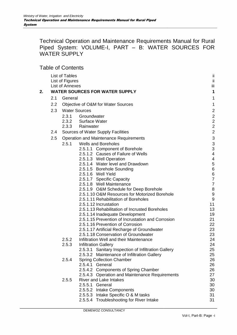


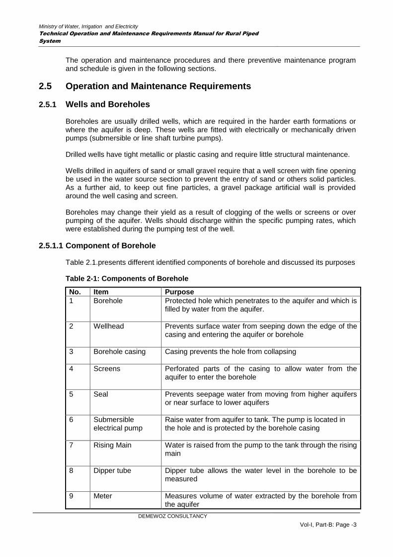
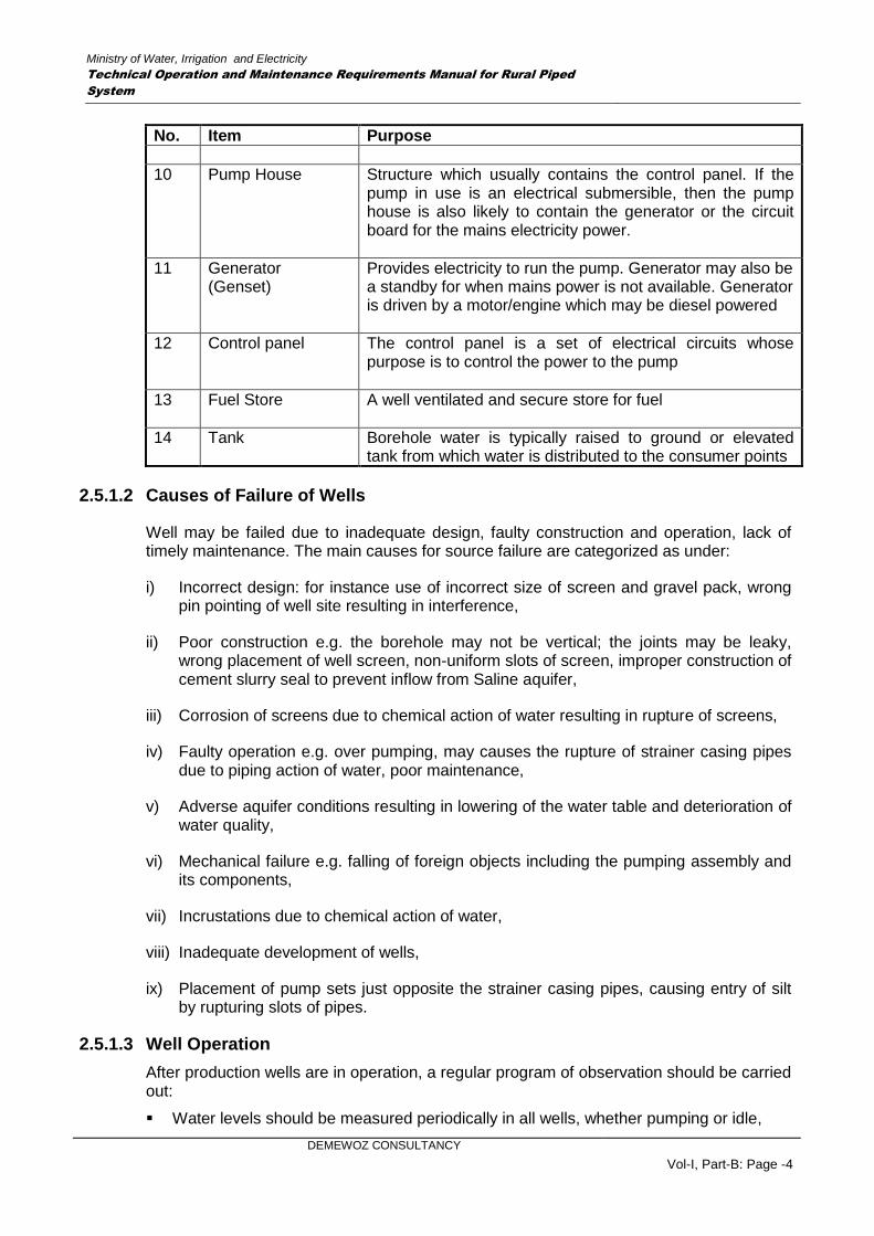
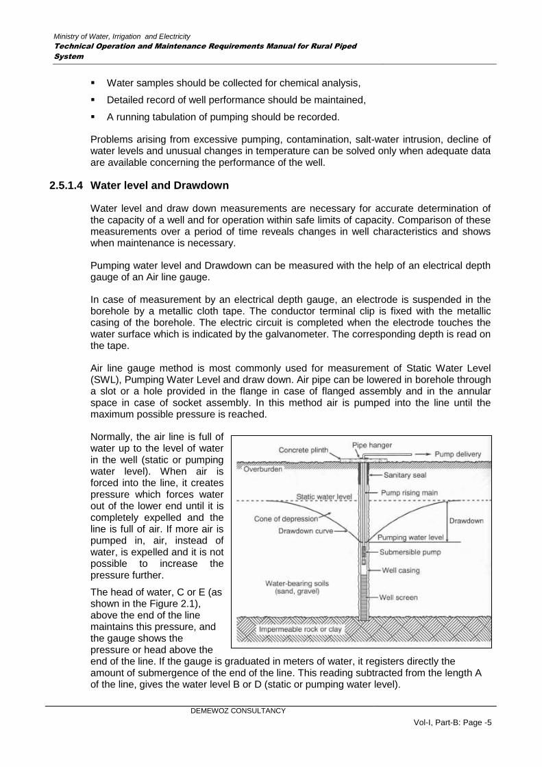
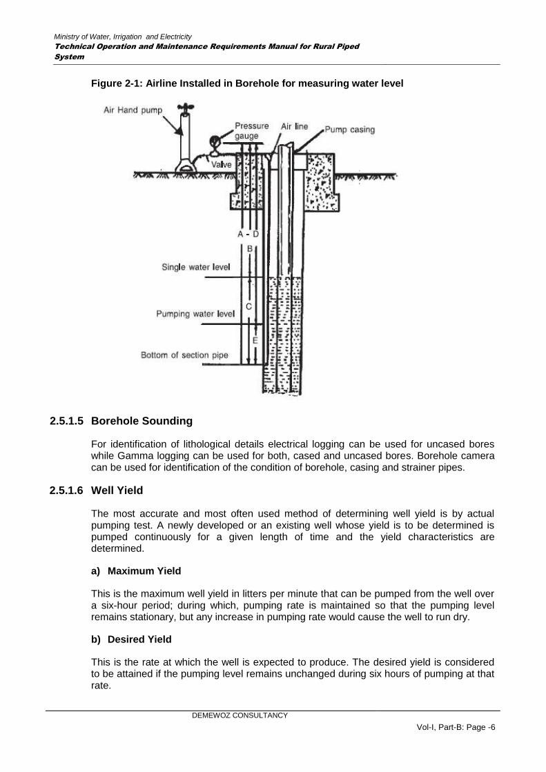


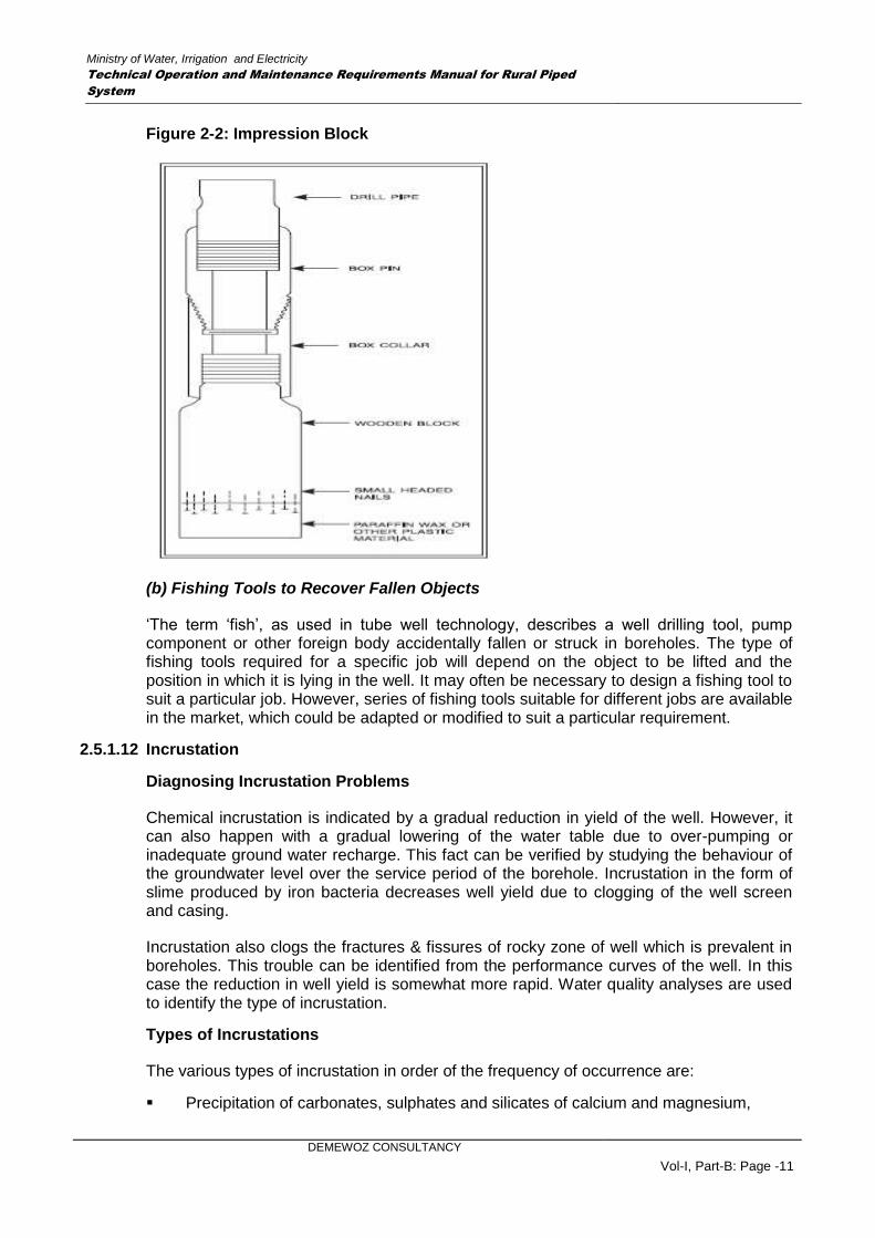


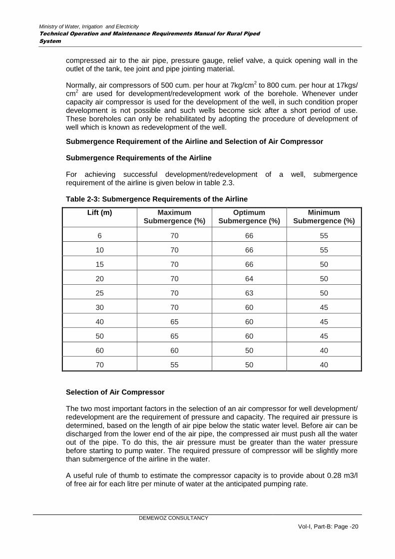
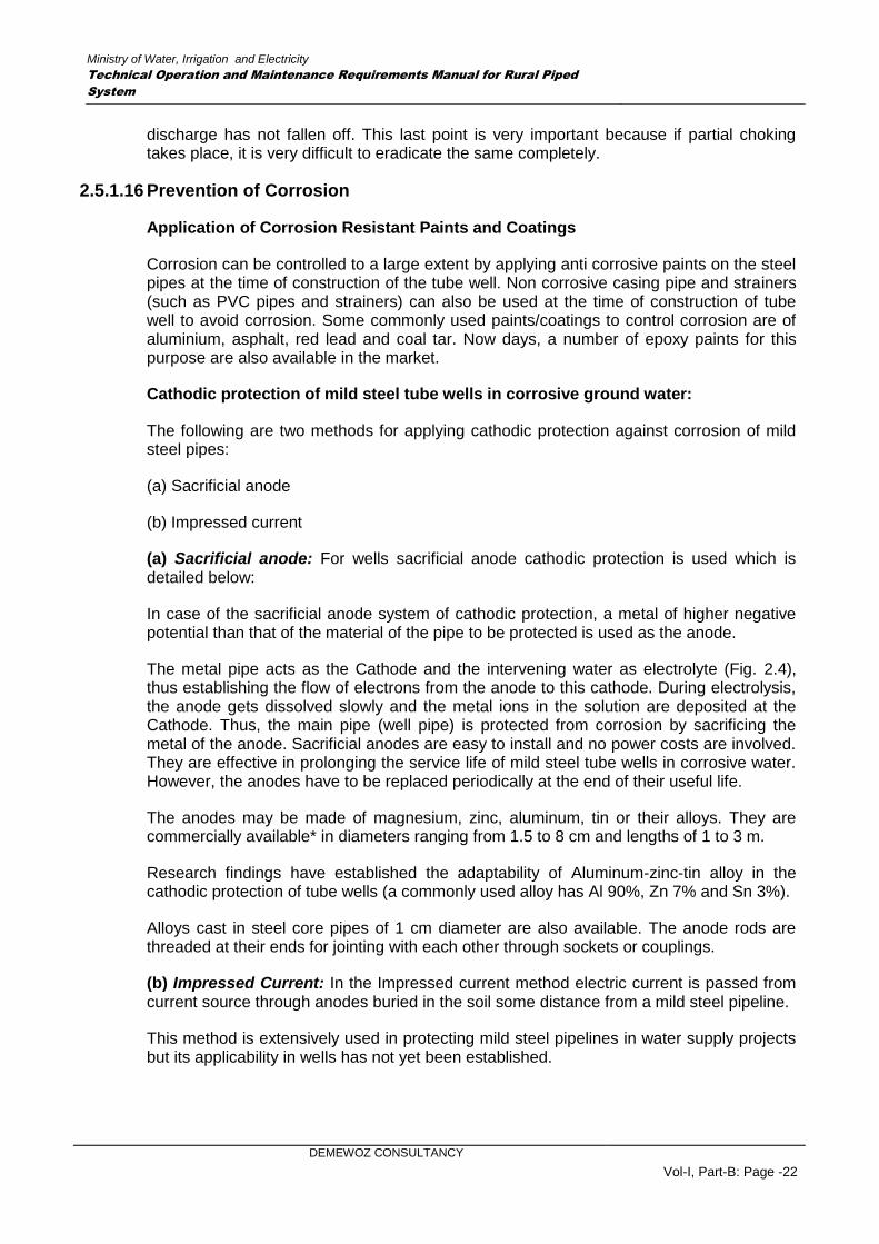
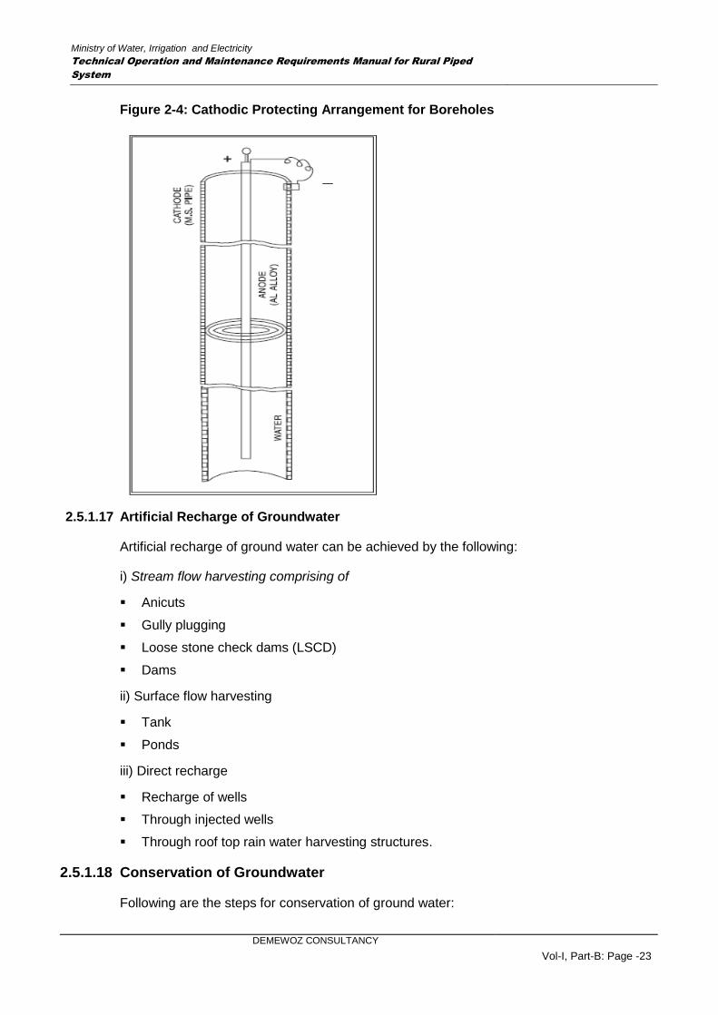
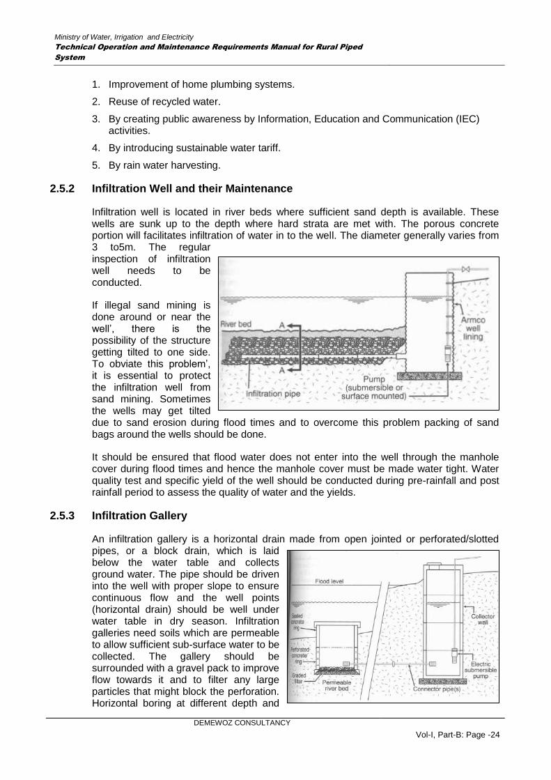

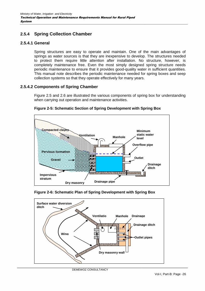


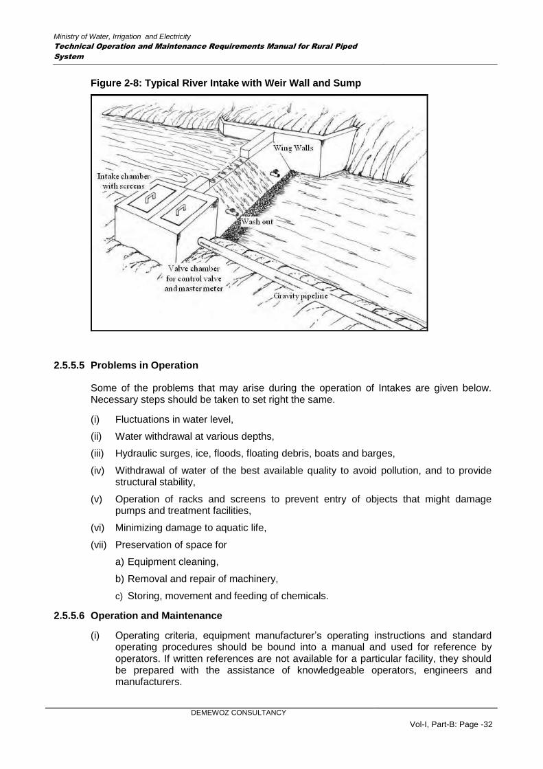

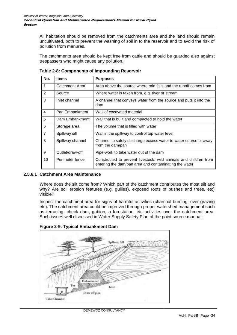
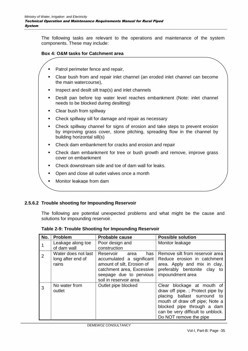
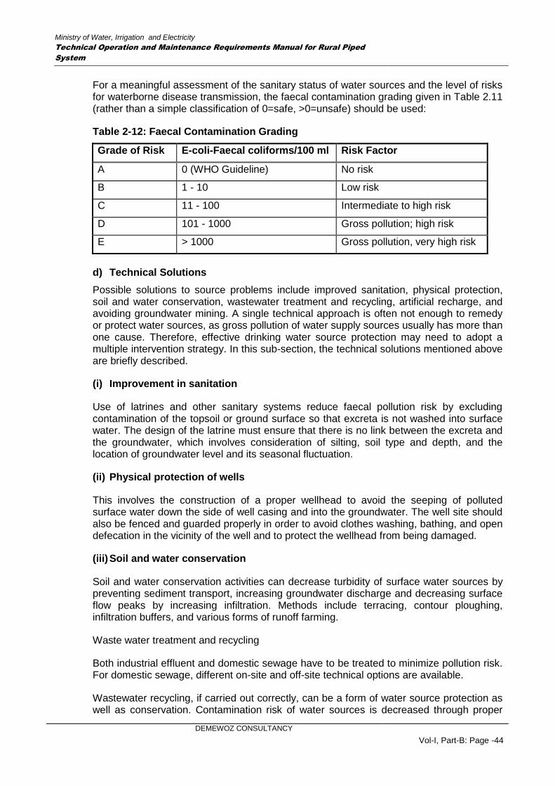
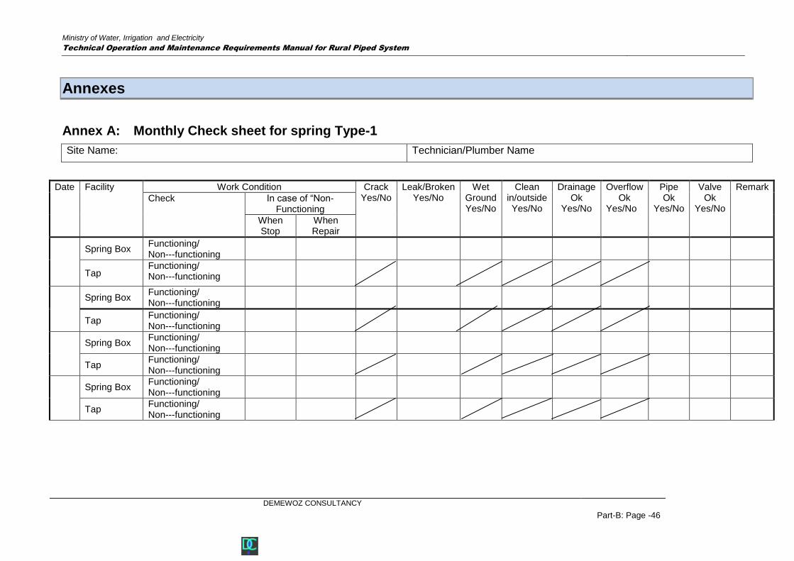
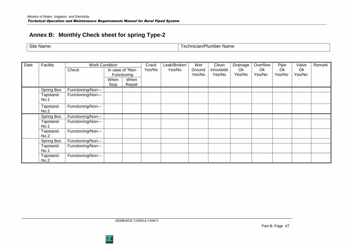
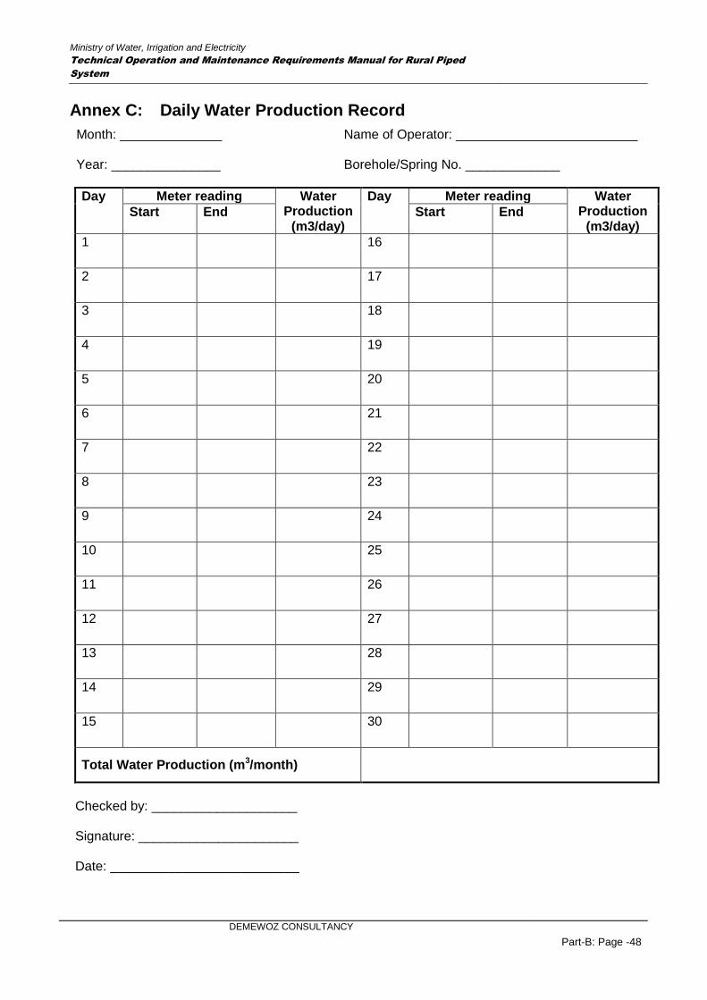
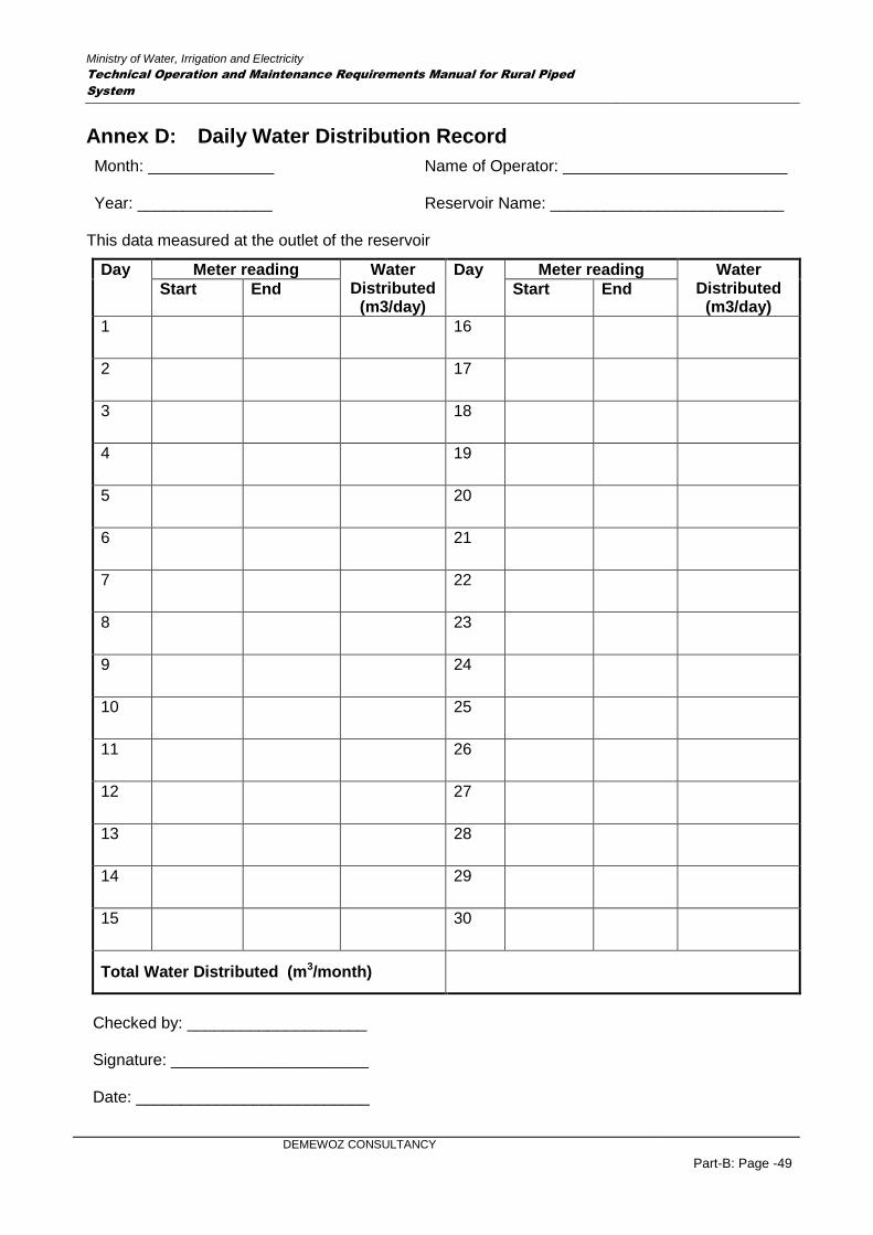


![The Sources of Water Supply, Sanitation Facilities and ......and stream waters are the main sources of drinking water in remote areas [3]. The drinking water source should meet the](https://static.documents.pub/doc/80x56/5ed2077760e784718e57287b/the-sources-of-water-supply-sanitation-facilities-and-and-stream-waters.jpg)


