2015 National Standard Plumbing Code - Illustrated 217 Water Supply and Distribution 10.1 QUALITY OF WATER SUPPLY a. Only potable water shall be supplied to plumbing fixtures used for drinking, bathing, culinary use or the processing of food, medical or pharmaceutical products. b. Reclaimed non-potable water shall be permitted in other than single dwelling units for flushing water closets and urinals, landscape irrigation, and other reuse applications in accordance with the requirements of the Authority Having Jurisdiction. c. Graywater in single dwelling units shall be limited to subsurface landscape irrigation in accordance with the requirements of the Authority Having Jurisdiction. d. Graywater in other than single dwelling units that is filtered and disinfected shall be permitted to be used for flushing water closets and urinals in accordance with the requirements of the Authority Having Jurisdiction. e. Harvested rainwater in other than single dwelling units that is filtered shall be permitted to be used for flushing water closets and urinals and subsurface landscape irrigation in accordance with the requirements of the Authority Having Jurisdiction. f. Reclaimed non-potable water, gray water, and harvested rain water, including the collection piping, distribution piping, storage and pumping equipment, shall be part of the plumbing system as covered by this Code regardless of their location on the property. 10.2 RESERVED 10.3 WATER REQUIRED Plumbing fixtures shall be provided with a supply of water in the amounts and at the pressures specified in this Chapter. 10.4 PROTECTION OF POTABLE WATER SUPPLY 10.4.1 General A potable water supply shall be designed, installed and maintained to prevent contamination from non- potable liquids, solids or gases by cross connections. 10.4.2 Interconnections Interconnections between two or more public water supplies shall be permitted only with the approval of the Authority Having Jurisdiction. 10.4.3 Cross Connection Control Potable water supplies shall be protected in accordance with the cross connection control program of the Authority Having Jurisdiction and the provisions of this Code. Cross connection control shall be provided at individual outlets, and where required, by containment of the premises. Each potential cross connection within the premises shall be protected. Where containment is required, the potable water supply shall be protected by a backflow prevention device installed immediately downstream of the meter or between the service shutoff valve and the first outlet or branch connection. See Figures 10.4.3-A and 10.4.3-B Chapter 10 Read Only Copy Not For Distribution
Transcript
2015 National Standard Plumbing Code - Illustrated 217
Water Supply and Distribution10.1 QUALITY OF WATER SUPPLY
a. Only potable water shall be supplied to plumbing fixtures used for drinking, bathing, culinary use or the processing of food, medical or pharmaceutical products.
b. Reclaimed non-potable water shall be permitted in other than single dwelling units for flushing water closets and urinals, landscape irrigation, and other reuse applications in accordance with the requirements of the Authority Having Jurisdiction.
c. Graywater in single dwelling units shall be limited to subsurface landscape irrigation in accordance with the requirements of the Authority Having Jurisdiction.
d. Graywater in other than single dwelling units that is filtered and disinfected shall be permitted to be used for flushing water closets and urinals in accordance with the requirements of the Authority Having Jurisdiction.
e. Harvested rainwater in other than single dwelling units that is filtered shall be permitted to be used for flushing water closets and urinals and subsurface landscape irrigation in accordance with the requirements of the Authority Having Jurisdiction.
f. Reclaimed non-potable water, gray water, and harvested rain water, including the collection piping, distribution piping, storage and pumping equipment, shall be part of the plumbing system as covered by this Code regardless of their location on the property.
10.2 RESERVED
10.3 WATER REQUIREDPlumbing fixtures shall be provided with a supply of water in the amounts and at the pressures specified in this Chapter.
10.4 PROTECTION OF POTABLE WATER SUPPLY
10.4.1 General
A potable water supply shall be designed, installed and maintained to prevent contamination from non- potable liquids, solids or gases by cross connections.
10.4.2 Interconnections
Interconnections between two or more public water supplies shall be permitted only with the approval of the Authority Having Jurisdiction.
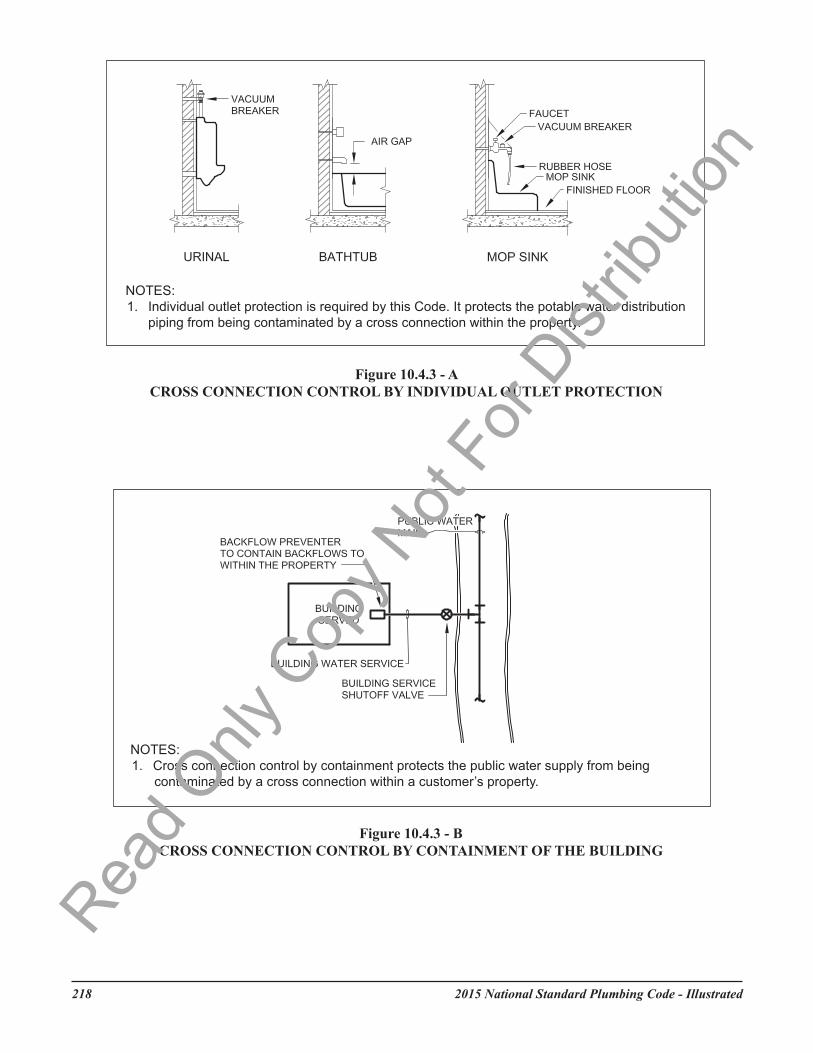
10.4.3 Cross Connection Control
Potable water supplies shall be protected in accordance with the cross connection control program of the Authority Having Jurisdiction and the provisions of this Code. Cross connection control shall be provided at individual outlets, and where required, by containment of the premises. Each potential cross connection within the premises shall be protected. Where containment is required, the potable water supply shall be protected by a backflow prevention device installed immediately downstream of the meter or between the service shutoff valve and the first outlet or branch connection.See Figures 10.4.3-A and 10.4.3-B
Chapter 10Rea
d Only
Cop
y Not
For D
istrib
ution
2015 National Standard Plumbing Code - Illustrated218
Figure 10.4.3 - B CROSS CONNECTION CONTROL BY CONTAINMENT OF THE BUILDING
218 2012 National Standard Plumbing Code - Illustrated
Read O
nly C
opy N
ot Fo
r Dist
ributi
on
2015 National Standard Plumbing Code - Illustrated 219
10.4.4 Private Supplies
a. Private potable water supplies (i.e., wells, cisterns, lakes, streams) shall require the same backflow prevention that is required for a public potable water supply.
b. Cross connection between a private potable water supply and a public potable water supply shall not be made unless specifically approved by the Authority Having Jurisdiction.
Comment: Interconnections between private water supplies and public water supplies are generally prohibited because private supplies are usually not monitored continuously for water quality.
10.4.5 Toxic Materials
a. Piping conveying potable water shall be constructed of non-toxic material.b. The interior surface of a potable water tank shall not be lined, painted, or repaired with any material
that will affect the taste, odor, color or potability of the water supply when the tank is placed in or returned to service.
Comment: The toxicity rating of a piping material can be found in the material standard listed in Table 3.1.3. The piping materials listed in Table 3.4 are non-toxic and are suitable for conveying potable water.
10.4.6 Reserved
10.4.7 Reserved
10.4.8 Used Materials
Materials that have been used for any purpose other than conveying potable water shall not be used for conveying potable water.
10.4.9 Water As a Heat-Transfer Fluid
Potable water may be used as a heat-transfer fluid provided that the potable water system is protected against cross connection.
10.5 BACKFLOW PREVENTION
10.5.1 Air Gaps
a. The water supply outlets for plumbing fixtures and other discharges shall be protected from back siphonage by a fixed air gap or a required backflow preventer.
b. Air gaps shall comply with ASME A112.1.2 or Table 10.5.2. Air gap fittings shall comply with ASME A112.1.3.
10.5.2 Requirements for Air Gaps
a. How Measured: Air gaps shall be measured vertically from the lowest opening of the water supply outlet to either (1) the flood level rim of the fixture or receptor served, or (2) the maximum elevation of the source of contamination.
b. Minimum size (distance): The minimum required air gap shall be in accordance with Table 10.5.2 based on the opening of the water supply outlet and the affect of any nearby vertical surfaces (walls).
Read O
nly C
opy N
ot Fo
r Dist
ributi
on
2015 National Standard Plumbing Code - Illustrated220
Table 10.5.2MINIMUM AIR GAPS FOR FIXTURES, APPLIANCES, AND WATER SUPPLY OUTLETS
Water Supply Outlet SizeMinimum Air Gap
Not Affected by Near Walls
Affected by One Near Wall
Affected by Two Near Walls
Outlets not greater than 1/2-inch diameter, including lavatory faucets
1 inch 1-1/2 inches 2 inches
Outlets not greater than 3/4-inch diameter, including sink faucets
1-1/2 inches 2-1/4 inches 3 inches
Outlets not greater than 1-inch diameter, including bathtub spouts
2 inches 3 inches 4 inches
Outlets greater than 1-inch diameter 2 times diameter 3 times diameter 4 times diameter
NOTES FOR TABLE 10.5.2:1. The listed outlet diameters in Table 10.5.2 are 1/2-inch, 3/4-inch, 1-inch, and greater than 1-inch. They should be used to
determine the affect of near walls (vertical surfaces) in Notes 2, 3, and 4 and the minimum required air gap. 2. The minimum air gaps for water supply outlets are not affected by near walls if a single wall is more than 3 times the
listed outlet diameter clearance from an edge of the outlet. If there are two walls, the clearances from both must be more than 4 times the listed outlet diameter for the air gap to be not affected.
3. If a water supply outlet has one near wall and the clearance is less than 3 times the listed outlet diameter from an edge of the outlet, the air gap must be sized as affected by one near wall.
4. If a water supply outlet has two near walls that both have clearances that are less than 4 times the listed outlet diameter from an edge of the outlet, the air gap must be sized as affected by two near walls.
Read O
nly C
opy N
ot Fo
r Dist
ributi
on
2015 National Standard Plumbing Code - Illustrated 221
10.5.3 Backflow Prevention Assemblies and Devices
The following requirements shall apply:A. Back Siphonage Only, Non-Continuous Water Pressure, Non-Health Hazards
B. Back Siphonage Only, Non-Continuous Water Pressure, Health and Non-Health Hazards 1. Air gaps in plumbing systems - ASME A112.1.2 2. Air gap fittings for use in plumbing fixtures, appliances, and appurtenances - ASME A112.1.3 3. Atmospheric type vacuum breaker - ASSE 1001
C. Back Siphonage Only, Continuous Water Pressure, Health or Non-Health Hazards 1. Pressure vacuum breaker assembly - ASSE 1020 2. Spill resistant vacuum breaker - ASSE 1056 (SVB)
D. Back Siphonage and Back Pressure, Continuous Water Pressure, Non-Health Hazards 1. Backflow preventer with intermediate atmospheric vent - ASSE 1012 2. Double check backflow prevention assembly - ASSE 1015 (DC) 3. Double check fire protection backflow prevention assembly - ASSE 1015 (DCF) 4. Dual check backflow preventer - ASSE 1024 5. Double check detector fire protection backflow prevention assembly - ASSE 1048 (DCDA) 6. Double check detector fire protection backflow prevention assembly - ASSE 1048 Type II (DCDA-II)
E. Back Siphonage and Back Pressure, Continuous Water Pressure, Health and Non-Health Hazards 1. Reduced pressure principle backflow preventer - ASSE 1013 (RP) 2. Reduced pressure principle fire protection backflow preventer - ASSE 1013 (RPF) 3. Reduced pressure detector fire protection backflow prevention assembly - ASSE 1047 (RPDA) 4. Reduced pressure detector fire protection backflow prevention assembly - ASSE 1047 Type II
(RPDA-II) F. Restrictions
1. Backflow preventers shall be applied within the ratings of their standard and their manufacturer’s instructions.
2. Backflow preventers with atmospheric vents shall not be located where discharge from their vent will cause water damage.
3. The following devices must not be subjected to more than 10 feet of water back pressure from elevated hoses:
a. ASSE 1011 hose connection vacuum breakers b. ASSE 1019 wall hydrants with backflow prevention and freeze resistance c. ASSE 1052 hose connection backflow preventers d. ASSE 1053 dual check backflow preventer wall hydrant - freeze resistant e. ASSE 1057 freeze resistant sanitary yard hydrants with backflow prevention 4. ASSE 1035 laboratory faucet backflow preventers must not be subjected to more than 6 inches of
water back pressure from elevated discharge hoses.
Read O
nly C
opy N
ot Fo
r Dist
ributi
on
2015 National Standard Plumbing Code - Illustrated222
10.5.4 Approval of Devices
Backflow prevention devices shall be listed or certified by a recognized certification body as complying with the appropriate standards in Table 3.1.3 - Part IX.
10.5.5 Installation of Backflow Preventers
a. All Types: All backflow preventers shall be accessible for testing (if testable), maintenance, repair, and replacement. Clearances shall be as recommended by the manufacturer. Backflow preventers having atmospheric vents shall not be installed in pits, vaults, or similar potentially submerged locations. Vacuum breakers and other devices with vents shall not be located within fume hoods. Where outdoor enclosures are provided for backflow prevention assemblies, they shall comply with ASSE 1060.
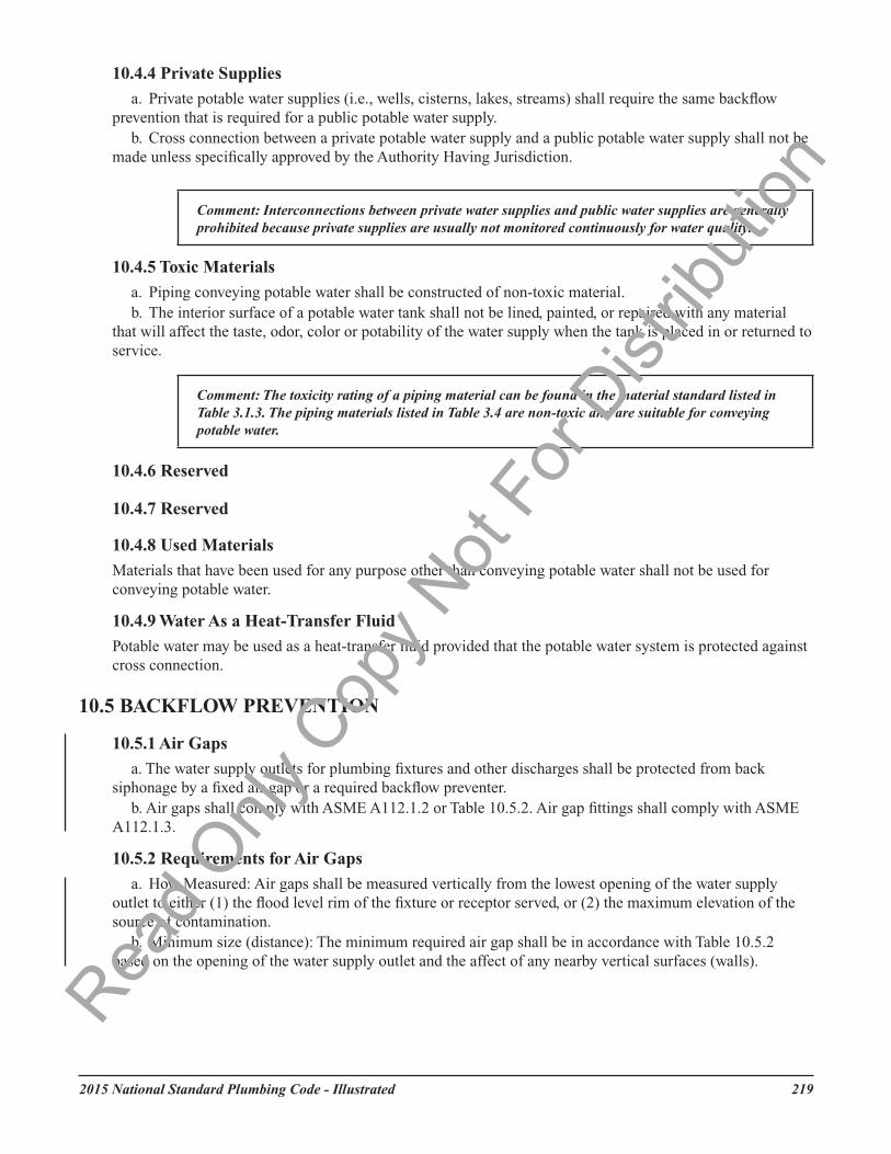
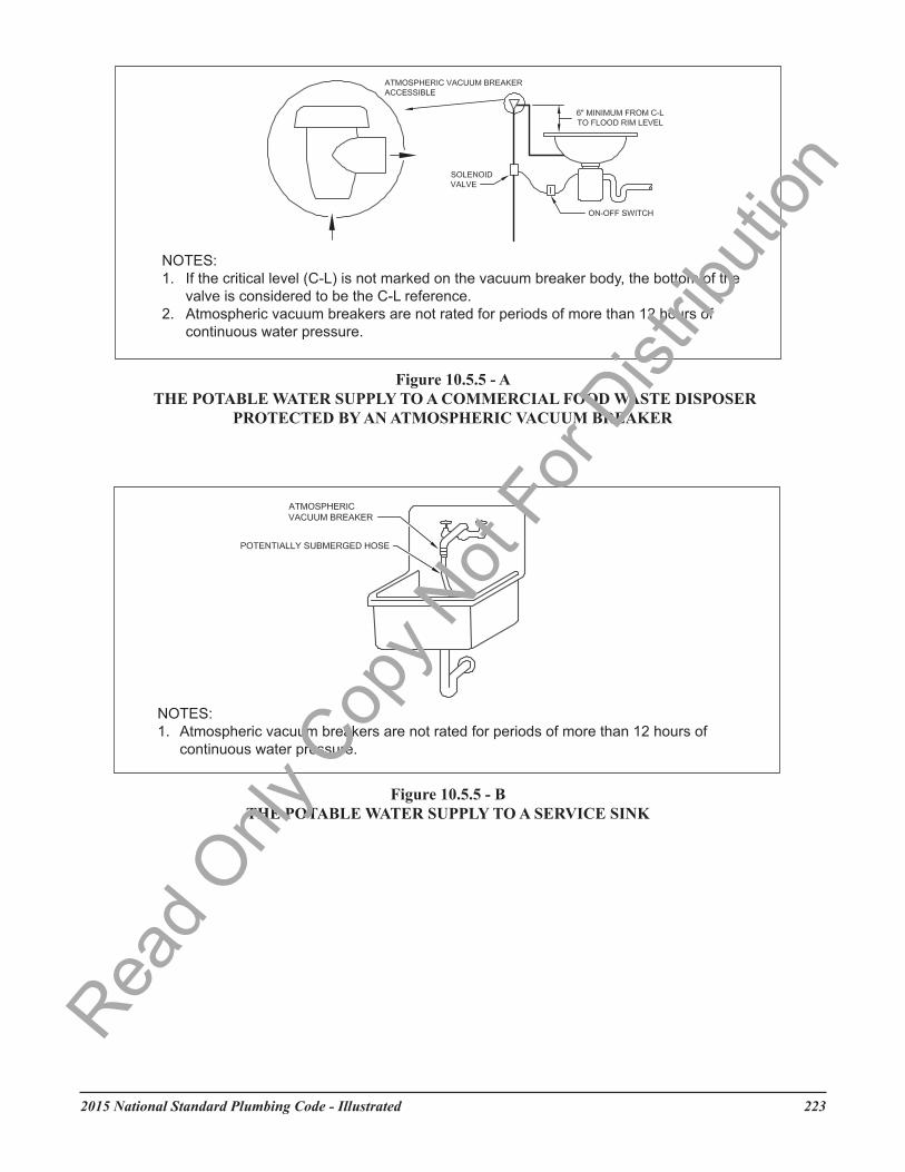
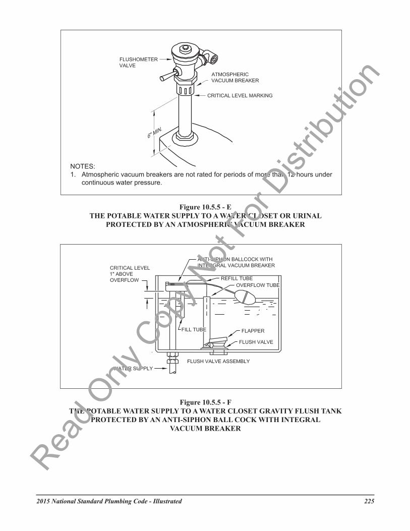
b. Atmospheric Vacuum Breakers: Pipe-applied atmospheric vacuum breakers shall be installed with the critical level not less than six inches above the flood level rim or highest point of discharge of the fixture being served. Approved deck-mounted and pipe-applied vacuum breakers and vacuum breakers within equipment, machinery and fixtures where the critical level is a specified distance above the source of contamination shall be installed in accordance with manufacturer’s instructions with the critical level not less than one inch above the flood level rim. Such devices shall be installed on the discharge side of the last control valve to the fixture and no shut-off valve or faucet shall be installed downstream of the vacuum breaker. Vacuum breakers on urinals shall be installed with the critical level not less than six inches above the highest part of the urinal. See Figures 10.5.5-A through 10.5.5-F.
c. Pressure Type Vacuum Breakers: Pressure type vacuum breakers shall be installed with the critical level at a height of at least 12 inches above the flood level rim for ASSE 1020 devices and with the critical level at least six inches above the flood level rim or highest point of discharge of the fixture being served for ASSE 1056 devices. Deck-mounted and pipe-applied pressure type (ASSE 1056) vacuum breakers within equipment, machinery and fixtures where the critical level is a specified distance above the source of contamination shall be installed in accordance with manufacturer’s instructions with the critical level not less than one inch above the flood level rim. See Figure 10.5.5-G.
d. Double Check Valves and Reduced Pressure Principle Valves: Such devices shall be installed at not less than 12 inches above the floor or permanent platform with the maximum of 60 inches above floor or permanent platform. See Figures 10.5.5-H and -I.
e. Spill-resistant Vacuum Breakers: Approved deck-mounted and pipe-applied spill-resistant vacuum breakers within equipment, machinery and fixtures where the critical level is a specified distance above the source of contamination shall be installed in accordance with manufacturer’s instructions with the critical level not less than one inch above the flood level rim.
Read O
nly C
opy N
ot Fo
r Dist
ributi
on
2015 National Standard Plumbing Code - Illustrated 223
NOTES:1. If the critical level (C-L) is not marked on the vacuum breaker body, the bottom of the
valve is considered to be the C-L reference.2. Atmospheric vacuum breakers are not rated for periods of more than 12 hours of
continuous water pressure.
Figure 10.5.5 - A THE POTABLE WATER SUPPLY TO A COMMERCIAL FOOD WASTE DISPOSER
PROTECTED BY AN ATMOSPHERIC VACUUM BREAKER
NOTES:1. Atmospheric vacuum breakers are not rated for periods of more than 12 hours of
continuous water pressure.
Figure 10.5.5 - B THE POTABLE WATER SUPPLY TO A SERVICE SINK
Read O
nly C
opy N
ot Fo
r Dist
ributi
on
2015 National Standard Plumbing Code - Illustrated224
Figure 10.5.5 - ETHE POTABLE WATER SUPPLY TO A WATER CLOSET OR URINAL
PROTECTED BY AN ATMOSPHERIC VACUUM BREAKER
Figure 10.5.5 - F THE POTABLE WATER SUPPLY TO A WATER CLOSET GRAVITY FLUSH TANK
PROTECTED BY AN ANTI-SIPHON BALL COCK WITH INTEGRAL VACUUM BREAKER
224 2012 National Standard Plumbing Code - Illustrated
Read O
nly C
opy N
ot Fo
r Dist
ributi
on
2015 National Standard Plumbing Code - Illustrated226
Read O
nly C
opy N
ot Fo
r Dist
ributi
on
2015 National Standard Plumbing Code - Illustrated 227
Read O
nly C
opy N
ot Fo
r Dist
ributi
on
2015 National Standard Plumbing Code - Illustrated228
10.5.6 Testing and Maintenance of Backflow Prevention Assemblies
a. Assemblies that are designed to be field tested shall be tested prior to final inspection of the initial installation and once each year thereafter.
b. Assemblies installed in a building potable water supply distribution system for protection against backflow shall be maintained in good working condition and be repaired when necessary.
c. Testable assemblies are those backflow prevention assemblies having test cocks or test procedures and include, but are not limited, to the following:
1. Reduced pressure principle backflow preventers (ASSE 1013) 2. Reduced pressure fire protection principle backflow preventers (ASSE 1013) 3. Double check backflow prevention assemblies (ASSE 1015) 4. Double check fire protection backflow prevention assemblies (ASSE 1015) 5. Pressure vacuum breaker assemblies (ASSE 1020) 6. Reduced pressure detector fire protection backflow prevention assemblies (ASSE 1047) 7. Double check detector fire protection backflow prevention assemblies (ASSE 1048) 8. Spill resistant vacuum breakers (ASSE 1056) d. Where tests indicate that the assembly is not functioning properly, it shall be serviced or repaired in
accordance with the manufacturer’s instructions and be retested.e. Testing and repair of assemblies shall be performed by certified individuals approved by an agency
acceptable to the Authority Having Jurisdiction. f. Certification for testing and repair shall be in accordance with the appropriate sections of ASSE 5000
Cross-Connection Control Professional Qualification Standard. Testing shall be in accordance with ASSE 5110 Backflow Prevention Assembly Testers. Repair shall be in accordance with ASSE 5130 Backflow Prevention Assembly Repairers.
g. Copies of test reports for the initial installation shall be sent to the Authority Having Jurisdiction and the water supplier. Copies of annual test reports shall be sent to the water supplier.
h. Where a continuous water supply is critical and cannot be interrupted for the periodic testing of a backflow prevention assembly, multiple backflow prevention assemblies or other means of maintaining a continuous supply shall be provided that does not create a potential cross connection.
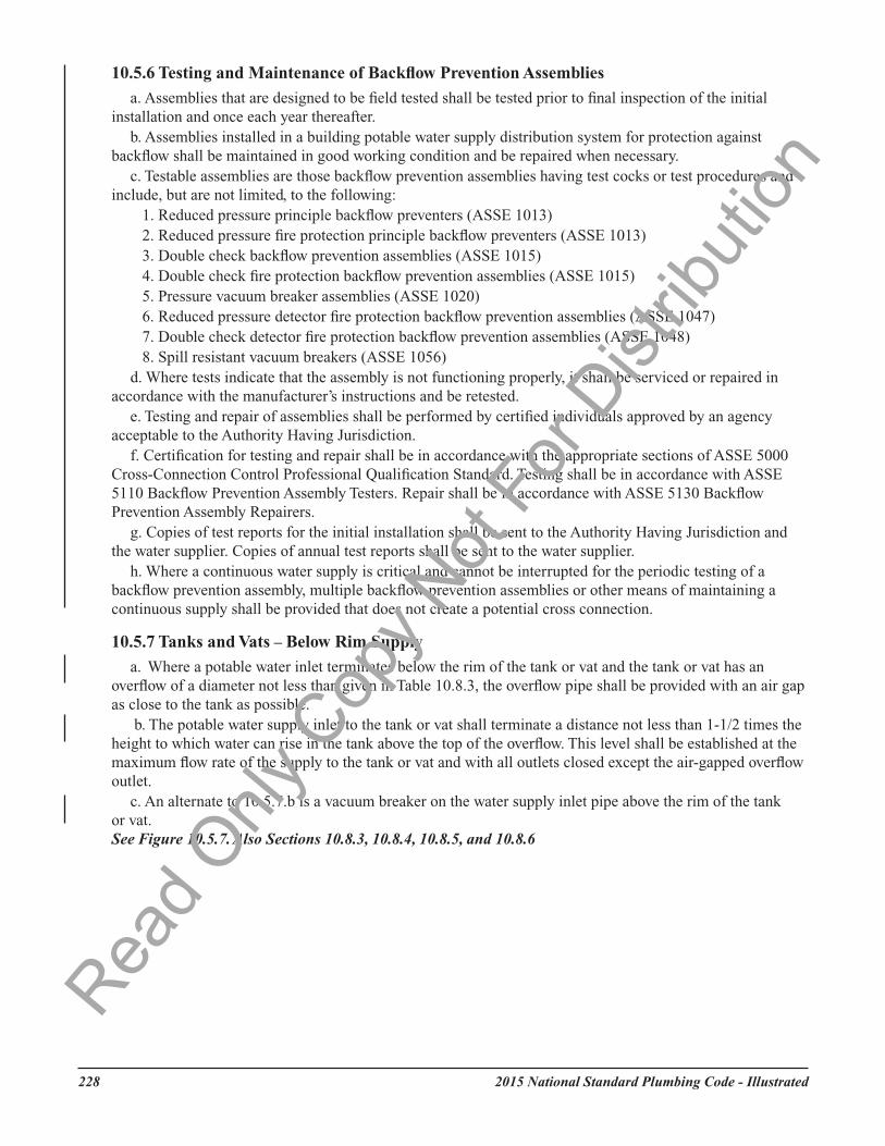
10.5.7 Tanks and Vats – Below Rim Supply
a. Where a potable water inlet terminates below the rim of the tank or vat and the tank or vat has an overflow of a diameter not less than given in Table 10.8.3, the overflow pipe shall be provided with an air gap as close to the tank as possible.
b. The potable water supply inlet to the tank or vat shall terminate a distance not less than 1-1/2 times the height to which water can rise in the tank above the top of the overflow. This level shall be established at the maximum flow rate of the supply to the tank or vat and with all outlets closed except the air-gapped overflow outlet.
c. An alternate to 10.5.7.b is a vacuum breaker on the water supply inlet pipe above the rim of the tank or vat. See Figure 10.5.7. Also Sections 10.8.3, 10.8.4, 10.8.5, and 10.8.6
Read O
nly C
opy N
ot Fo
r Dist
ributi
on
2015 National Standard Plumbing Code - Illustrated 229
10.5.8 Protection from Equipment in Food Establishments
a. Food preparation and service equipment in food establishments that is connected to potable water piping or drained to waste piping shall be protected from backflow to the potable water system and from contamination of equipment, food, and utensils.
b. Fixtures that require an air gap in their water supply above the flood level rim of the fixture include, but are not limited to, sink faucets, dipper wells, pot fillers, and spray arms in dish areas.
c. Equipment that requires an air gapped waste line includes, but is not limited to, walk-in coolers, food prep sinks, dipper wells, ice machines, ice bins, steam tables, bains-marie, Chinese ranges (woks), combination steamer/ovens, rethermalizers, steamers, kettles, non-evaporating reach-in coolers, soda gun holsters, and water treatment systems.
Read O
nly C
opy N
ot Fo
r Dist
ributi
on
2015 National Standard Plumbing Code - Illustrated230
d. Equipment that requires a pressure vacuum breaker or spill resistant vacuum breaker in its water supply includes, but is not limited to, Chinese ranges (woks), rethermalizers, hoses with a pressure nozzle, and pasta cookers.
e. Equipment that requires an atmospheric vacuum breaker in its water supply includes, but is not limited to, garbage disposals, automatic dishwashers, dish machine automatic detergent feeders, detergent feeders for 3-compartment sinks, wall-mounted chemical feeders, garbage can washers, mop sinks, steam tables with submerged inlets, and dish troughs with submerged inlets.
f. Equipment that requires a vented double check valve or equivalent in its water supply includes, but is not limited to, untreated boilers such as expresso machines, the oven in combination steamer/ovens, carbonated beverage machines, beverage carbonators, non-carbonated beverage machines, coffee machines, iced tea machines, hot chocolate machines, cappuccino machines, instant hot water dispensers, slushy machines, and any other beverage equipment.
g. The water supply to a post-mix carbonated beverage dispenser shall be protected against backflow with an integral backflow preventer conforming to ASSE 1022 or an air gap.
1. Post-mix carbonated beverage dispensers and carbonated beverage systems with an integral dual check backflow preventer without an atmospheric vent (ASSE 1032) or without an integral backflow preventer conforming to ASSE 1022 or without an integral air gap shall have the water supply connection to the dispenser protected by a double check valve with atmospheric vent port conforming to ASSE 1022.
2. When an ASSE 1022 device must be installed in the water supply piping external to the carbonated beverage dispenser, the piping from the device to the beverage dispenser shall be acid-resistant and not copper.
3. ASSE 1012 backflow preventers with intermediate atmospheric vents are not constructed for use with carbonated beverages and shall not be used for backflow prevention from post-mix carbonated beverage dispensers. h. All backflow prevention assemblies and devices shall be installed in accordance with their
manufacturer’s instructions for the particular application.
10.5.9 Protection from Fire Systems
a. Potable water supplies to water-based fire protection systems, including but not limited to standpipes and automatic sprinkler systems, shall be protected from back pressure and back siphonage by one of the following testable assemblies:
1. double check fire protection backflow prevention assembly – ASSE 1015 (DCF)2. double check detector fire protection backflow prevention assembly – ASSE 1048 (DCDA or
DCDA-II)3. reduced pressure fire protection principle backflow prevention assembly – ASSE 1013 (RPF)4. reduced pressure detector fire protection backflow prevention assembly – ASSE 1047 (RPDA or
RPDA-II). EXCEPTIONS:
(1) ASSE 1024 dual check backflow preventers shall be permitted in stand-alone residential fire sprinkler systems that comply with NFPA 13D or NFPA 13R, do not supply plumbing fixtures, and do not include a fire department connection.
(2) Backflow preventers shall not be required in NFPA 13D multipurpose or network residential fire sprinkler systems that supply both plumbing fixtures and residential fire sprinklers. The piping in such systems shall be approved for potable water. Such systems shall not have a fire department connection.
(3) ASSE 1024 dual check backflow preventers shall be permitted in limited area fire sprinkler systems that comply with NFPA 13 and do not have a fire department connection.
(4) Where fire protection systems include a fire department connection, ASSE 1013 reduced pressure fire protection principle backflow preventers (RPF) or ASSE 1047 reduced pressure detector fire protection backflow prevention assemblies (RPDA or RPDA-II) shall be required.Rea
d Only
Cop
y Not
For D
istrib
ution
2015 National Standard Plumbing Code - Illustrated 231
(5) Where fire protection systems are filled with solutions that are considered to be health hazards as defined in Section 1.2, ASSE 1013 reduced pressure fire protection principle backflow preventers (RPF) or ASSE 1047 reduced pressure detector fire protection backflow prevention assemblies (RPDA or RPDA-II) shall be required.
b. Whenever a backflow prevention assembly is installed in a potable water supply to a fire protection system, the hydraulic design of the fire protection system shall account for the pressure drop through the backflow prevention assembly.
c. If a backflow prevention assembly is retrofitted for an existing fire protection system, the hydraulics of the fire protection system shall be checked to verify that there will be sufficient water pressure available for satisfactory operation of the fire protection system with the backflow prevention assembly in place.
10.5.10 Protection from Lawn Sprinklers and Irrigation Systems
a. Potable water supplies to systems having no pumps or connections for pumping equipment, and no chemical injection or provisions for chemical injection, shall be protected from backflow by one of the following:
b. Where lawn sprinkler and irrigation systems have pumps, connections for pumping equipment, auxiliary air tanks or are otherwise capable of creating back pressure, the potable water supply shall be protected by the following type of device if the backflow prevention device is located upstream from the source of back pressure.
1. Reduced pressure principle backflow preventer – ASSE 1013 (RP) c. Where systems have a backflow preventer installed downstream from a potable water supply pump or a
potable water supply pump connection, the preventer shall be one of the following:1. Atmospheric type vacuum breaker – ASSE 1001 (for non-continuous pressure) 2. Pressure vacuum breaker assembly (PVB) – ASSE 1020 3. Spill resistant vacuum breaker (SVB) – ASSE 1056 4. Reduced pressure principle backflow preventer – ASSE 1013 (RP)
d. Where systems include a chemical injector or any provisions for chemical injection, the potable water supply shall be protected by the following:
a. Heat exchangers used for heat transfer, heat recovery, or solar heating shall protect the potable water system from being contaminated by the heat transfer medium, in accordance with either subparagraph b or c below.
b. Single-wall heat exchangers shall be permitted if they satisfy all of the following requirements:1. The heat transfer medium is either potable water or contains only substances that are recognized as
safe by the U.S. Food and Drug Administration.2. The pressure of the heat transfer medium is maintained less than the normal minimum operating
pressure of the potable water system.EXCEPTION: Steam complying with subparagraph b.1.
3. The equipment is permanently labeled to indicate that only additives recognized as safe by the FDA shall be used in the heat transfer medium.c. Double-wall heat exchangers shall separate the potable water from the heat transfer medium by
providing a space between the two walls that is vented to the atmosphere.Read O
nly C
opy N
ot Fo
r Dist
ributi
on
2015 National Standard Plumbing Code - Illustrated232
10.5.12 Protection from Hose Connections
A pressure-type or atmospheric-type vacuum breaker or permanently attached hose connection vacuum breaker shall protect hose bibbs, sill-cocks, wall hydrants and other outlets having a hose connection. The backflow preventer shall not be subjected to continuous pressure and shall be limited to low-head back pressure of not more than 10 feet of water from an elevated hose.EXCEPTIONS:
(1) Water heater and boiler drain valves that are provided with hose connection threads and that are intended only for tank or vessel draining shall not be required to be equipped with a backflow preventer.
(2) This section shall not apply to water supply valves intended for connection to clothes washing machines where backflow prevention is otherwise provided or is integral with the machine.
10.5.13 Protection from Special Equipment
The water supply for any equipment or device that creates a cross-connection with the potable water supply shall be protected against backflow as required in Section 10.5. Such equipment and devices includes, but is not limited to, chemical dispensers, portable cleaning equipment, sewer and drain cleaning equipment, and dental pump equipment.
a. Chemical Dispensing SystemsChemical dispensing systems with connections to the potable water distribution system shall protect
the water distribution systems from backflow in accordance with ASSE 1055, which requires an air gap, atmospheric vacuum breaker, pressure vacuum breaker, spill resistant vacuum breaker, or reduced pressure principle assembly.
EXCEPTION: Atmospheric vacuum breakers shall not be used where there are shutoff valves or other shutoff devices downstream or where they are subject to continuous pressure for more than 12 hours in a 24 hour period.
b. Portable Cleaning EquipmentWhere the water distribution system connects to portable cleaning equipment, the water supply system
shall be protected against backflow in accordance with Section 10.5, which allows for an atmospheric vacuum breaker, pressure vacuum breaker, double check valve, or a reduced pressure principle assembly.
EXCEPTION: Atmospheric vacuum breakers shall not be used where there are shutoff valves or other shutoff devices downstream or where they are subject to continuous pressure for more than 12 hours at a time.
c. Dental Pump EquipmentWhere the water distribution system connects to dental pumping equipment, the water supply system shall
be protected against backflow in accordance with Section 10.5, which allows for an atmospheric vacuum breaker, pressure vacuum breaker, double check valve, or a reduced pressure principle assembly.
EXCEPTION: Atmospheric vacuum breakers shall not be used where there are shutoff valves or other shutoff devices downstream or where they are subject to continuous pressure for more than 12 hours at a time.
d. Water Powered Back-up Sump Pumps 1. The potable water supply to water powered back-up sump pumps shall be protected against
backflow by an ASSE 1013 (RP) reduced pressure principle backflow preventer. Vacuum breakers shall not be permitted.
2. Pump control valves, ejectors, and discharge piping shall be installed in accordance with the manufacturer’s instructions. e. Laboratory Sink Faucets Faucets on laboratory sinks shall be protected against backflow from back siphonage and back pressure
by the attachment of an ASSE 1035 laboratory faucet backflow preventer. The backflow preventer shall not be subjected to constant supply pressure and there shall be no shutoff devices downstream. The backflow preventer shall be limited to back pressure of not more than 6 inches of water elevation beyond its outlet.Rea
d Only
Cop
y Not
For D
istrib
ution
2015 National Standard Plumbing Code - Illustrated 233
10.6 WATER SERVICE
10.6.1 Separation of Water Service Piping from Drainage Piping and Non-Potable Water Piping. Underground water service piping shall be separated by not less than one foot horizontally from building drain piping, building sewer piping, and non-potable water piping, including reclaimed water, gray water, and harvested rainwater. See Figure 10.6.1-A and 10.6.1-B
Figure 10.6.1 - ATHE MINIMUM DISTANCE BETWEEN AN UNDERGROUND WATER SERVICE
2012 National Standard Plumbing Code - Illustrated 231
10.6 WATER SERVICE
10.6.1 Separation of Water Service Piping from Drain Piping and Non-Potable Water Piping.Underground water service piping shall be separated by not less than one foot horizontally from building drain piping, building sewer piping, and non-potable water piping, including reclaimed water, gray water, and harvested rainwater. See Figure 10.6.1-A and 10.6.1-B
Read O
nly C
opy N
ot Fo
r Dist
ributi
on
2015 National Standard Plumbing Code - Illustrated234
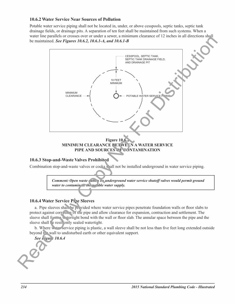
10.6.2 Water Service Near Sources of Pollution
Potable water service piping shall not be located in, under, or above cesspools, septic tanks, septic tank drainage fields, or drainage pits. A separation of ten feet shall be maintained from such systems. When a water line parallels or crosses over or under a sewer, a minimum clearance of 12 inches in all directions shall be maintained. See Figures 10.6.2, 10.6.1-A, and 10.6.1-B
10.6.3 Stop-and-Waste Valves Prohibited
Combination stop-and-waste valves or cocks shall not be installed underground in water service piping.
Comment: Open waste outlets on underground water service shutoff valves would permit ground water to contaminate the potable water supply.
10.6.4 Water Service Pipe Sleeves
a. Pipe sleeves shall be provided where water service pipes penetrate foundation walls or floor slabs to protect against corrosion of the pipe and allow clearance for expansion, contraction and settlement. The sleeve shall form a watertight bond with the wall or floor slab. The annular space between the pipe and the sleeve shall be resiliently sealed watertight.
b. Where water service piping is plastic, a wall sleeve shall be not less than five feet long extended outside beyond the wall to undisturbed earth or other equivalent support.
See Figure 10.6.4
10.6.2 Water Service Near Sources of Pollution Potable water service piping shall not be located in, under, or above cesspools, septic tanks, septic tank drainage fields, or drainage pits. A separation of ten feet shall be maintained from such systems. When a water line parallels or crosses over or under a sewer, a minimum clearance of 12 inches in all directions shall be maintained. See Figures 10.6.2, 10.6.1-A, and 10.6.1-B
10.6.3 Stop-and-Waste Valves Prohibited Combination stop-and-waste valves or cocks shall not be installed underground in water service piping.
Comment: Open waste outlets on underground water service shutoff valves would permit ground water to contaminate the potable water supply.
10.6.4 Water Service Pipe Sleeves a. Pipe sleeves shall be provided where water service pipes penetrate foundation walls or floor slabs to
protect against corrosion of the pipe and allow clearance for expansion, contraction and settlement. The sleeve shall form a watertight bond with the wall or floor slab. The annular space between the pipe and the sleeve shall be resiliently sealed watertight.
b. Where water service piping is plastic, a wall sleeve shall be not less than five feet long extended outside beyond the wall to undisturbed earth or other equivalent support.See Figure 10.6.4
Figure 10.6.2 MINIMUM CLEARANCE BETWEEN A WATER SERVICE
PIPE AND SOURCES OF CONTAMINATION
232 2012 National Standard Plumbing Code - Illustrated
Read O
nly C
opy N
ot Fo
r Dist
ributi
on
2015 National Standard Plumbing Code - Illustrated 235
Figure 10.6.4 WATER SERVICE PIPE SLEEVES FOR METALLIC AND PLASTIC PIPING
2012 National Standard Plumbing Code - Illustrated 233
Read O
nly C
opy N
ot Fo
r Dist
ributi
on
2015 National Standard Plumbing Code - Illustrated236
10.6.5 Water Service Sizing
The water service pipe shall be of sufficient size to furnish water to the building in the quantities and at the pressures required elsewhere in this Code. The pipe size shall not be less than 3/4 inch nominal.
10.7 WATER PUMPING AND STORAGE EQUIPMENT
10.7.1 Pumps and Other Appliances
Water pumps, filters, softeners, tanks and other appliances and devices used to handle or treat potable water shall be protected against contamination as per Section 10.5.
10.7.2 Prohibited Location of Potable Supply Tanks
Potable water gravity tanks or manholes of potable water pressure tanks shall not be located directly under any sanitary drain piping.
10.8 WATER PRESSURE BOOSTER SYSTEMS
10.8.1 Water Pressure Booster Systems Required
a. When the water pressure in the public water main or individual water supply system is insufficient to supply the potable peak demand flow to plumbing fixtures and other water needs freely and continuously with the minimum pressure and quantities specified in Section 10.14.3, or elsewhere in this Code, and in accordance with good practice, the rate of supply shall be supplemented by one of the following methods:
1. An elevated water tank.2. A hydro-pneumatic pressure booster system.3. A water pressure booster pump.
10.8.2 Reserved
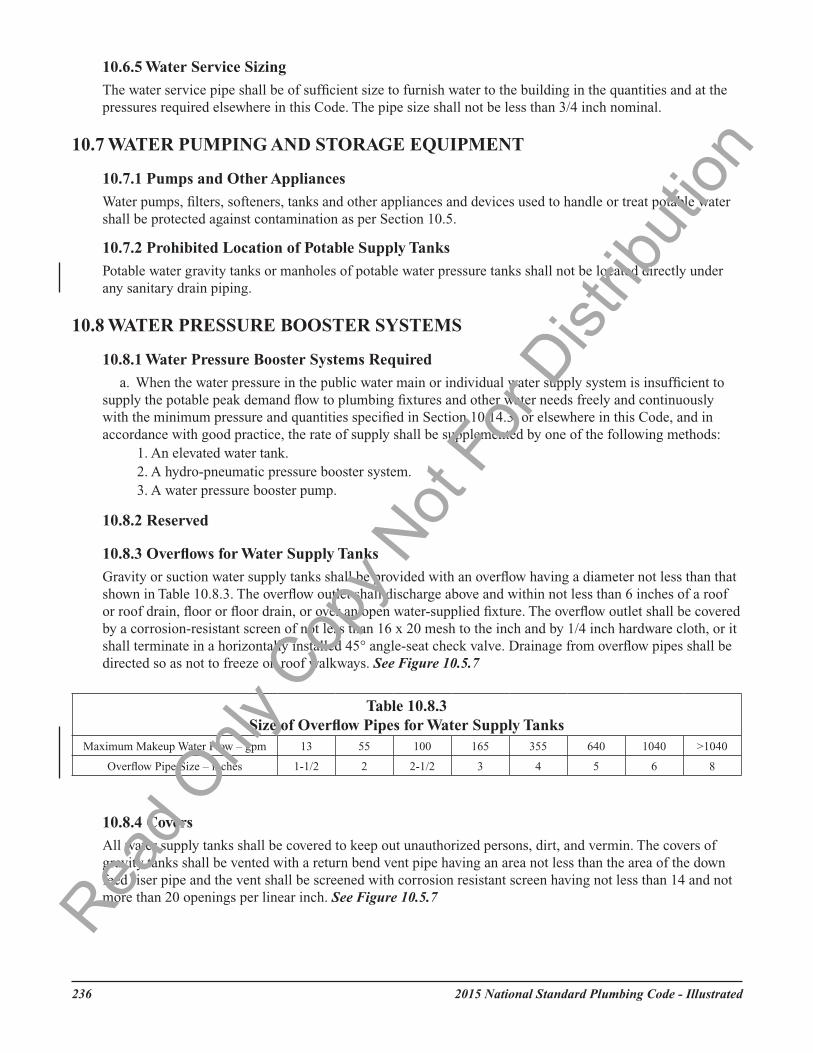
10.8.3 Overflows for Water Supply Tanks
Gravity or suction water supply tanks shall be provided with an overflow having a diameter not less than that shown in Table 10.8.3. The overflow outlet shall discharge above and within not less than 6 inches of a roof or roof drain, floor or floor drain, or over an open water-supplied fixture. The overflow outlet shall be covered by a corrosion-resistant screen of not less than 16 x 20 mesh to the inch and by 1/4 inch hardware cloth, or it shall terminate in a horizontally installed 45° angle-seat check valve. Drainage from overflow pipes shall be directed so as not to freeze on roof walkways. See Figure 10.5.7
10.8.4 Covers
All water supply tanks shall be covered to keep out unauthorized persons, dirt, and vermin. The covers of gravity tanks shall be vented with a return bend vent pipe having an area not less than the area of the down feed riser pipe and the vent shall be screened with corrosion resistant screen having not less than 14 and not more than 20 openings per linear inch. See Figure 10.5.7
Table 10.8.3Size of Overflow Pipes for Water Supply Tanks
Maximum Makeup Water Flow – gpm 13 55 100 165 355 640 1040 >1040
2015 National Standard Plumbing Code - Illustrated 237
10.8.5 Potable Water Inlet Control and Location
Potable water inlets to gravity water tanks shall be controlled by a level control valve or other automatic supply valve so installed as to control the water level in the tank and prevent the tank from overflowing. The inlet shall be terminated so as to provide an air gap above the overflow level of the tank in accordance with Table 10.5.2. See Figure 10.5.7
10.8.6 Tank Drain Pipes
Each tank shall be provided at its lowest point with a valved pipe to permit emptying the tank.See Figure 10.5.7
10.8.7 Low Pressure Cut-Off Required on Booster Pumps
Booster pumps shall be protected by a low pressure cut-off switch to shut-off the pump(s) if the suction pressure drops to an unsafe value.
10.8.8 Pressure Tanks—Vacuum Relief
Domestic water pressure tanks shall be provided with vacuum relief if required by Section 10.16 .7 or the tank manufacturer.
10.8.9 Pressure Tanks—Pressure Relief
All water pressure tanks shall be provided with approved pressure relief valves set at a pressure not in excess of the tank working pressure.
10.9 FLUSHING AND DISINFECTING POTABLE WATER SYSTEMS
10.9.1 Flushing
The water service piping and distribution piping to all fixtures and outlets shall be flushed until the water runs clear and free of debris or particles. Faucet aerators or screens shall be removed during flushing operations.
10.9.2 Disinfecting
a. Water service piping and hot and cold water distribution piping in new or renovated potable water systems shall be disinfected after flushing and prior to use. EXCEPTION: Single dwelling units with public water supply.
b. The procedure used shall be as follows or an approved equivalent:1. All water outlets shall be posted to warn against use during disinfecting operations.2. Disinfecting shall be performed by persons experienced in such work.3. The water supply to the piping system or parts thereof being disinfected shall be valved-off from
the normal water source to prevent the introduction of disinfecting agents into a public water supply or portions of a system that are not being disinfected.
4. The piping shall be disinfected with a water-chlorine solution. During the injection of the disinfecting agent into the piping, each outlet shall be fully opened several times until a concentration of not less than 50 parts per million chlorine is present at every outlet. The solution shall be allowed to stand in the piping for at least 24 hours.
5. An acceptable alternate to the 50 ppm/24-hour procedure described in Section 10.9.2.b.4 shall be to maintain a level of not less than 200 parts per million chlorine for not less than three hours. If this alternate procedure is used, the heavily concentrated chlorine shall not be allowed to stand in the piping system for more than 6 hours. Also, special procedures shall be used to dispose of the heavily concentrated chlorine in an environmentally acceptable and approved manner.
6. At the end of the required retention time, the residual level of chlorine at every outlet shall be not less than five parts per million. If the residual is less than five parts per million, the disinfecting procedure shall be repeated until the required minimum chlorine residual is obtained at every outlet.
Read O
nly C
opy N
ot Fo
r Dist
ributi
on
2015 National Standard Plumbing Code - Illustrated238
7. After the required residual chlorine level is obtained at every outlet, the system shall be flushed to remove the disinfecting agent. Flushing shall continue until the chlorine level at every outlet is reduced to that of the incoming water supply.
8. Any faucet aerators or screens that were removed under Section 10.9.1 shall be replaced.9. A certification of performance and laboratory test report showing the absence of coliform organisms
shall be submitted to the Authority Having Jurisdiction upon satisfactory completion of the disinfecting operations.
10.9.3 Additions to Existing Systems
Where new piping is required to be flushed and disinfected, if a new addition or additions to an existing domestic water piping system can be completely isolated from the existing system for the purpose of flushing and disinfecting, only the new piping shall be required to be flushed and disinfected.
10.10 WATER SUPPLY SYSTEM MATERIALSSee Sections 3.4.2 and 3.4.3.
10.11 ALLOWANCE FOR CHARACTER OF SOIL AND WATERWhen selecting the material and size for water service supply pipe, tube, or fittings, due consideration shall be given to the action of the water on the interior of the pipe and of the soil, fill or other material on the exterior of the piping.
Comment: The chemical composition of the service water should be considered when selecting the water service pipe material. Refer to Appendix Section B.2.3. The aggressive nature of the soil or fill material around the water service pipe should be evaluated when considering if additional corrosion protection is need for the exterior surfaces of the pipe.
10.12 WATER SUPPLY CONTROL VALVES
10.12.1 Curb Valve
On the water service from the street main to the building, an approved gate valve or ground key stopcock or ball valve shall be installed near the curb line between the property line and the curb. This valve or stopcock shall be provided with an approved curb valve box. See Figure 1.2.82
10.12.2 Building Valve
a. The building water service shall be provided with a readily accessible gate valve or other full-way shutoff valve located inside the building near the point where the water service enters. See Figure 1.2.82
b. Provisions shall be made to drain the piping immediately downstream from the building valve for service or maintenance. Drains shall be capped or plugged to prevent them from being inadvertently discharged. Bleed valves shall be permitted to satisfy this requirement.
c. If a building has two or more water services that are interconnected within the building, full-size check valves shall be installed near the outlets of the building valves to prevent backflow from one water service to another. Pressure test connections shall be provided on both sides of the check valves.
EXCEPTION: Check valves shall not be required if the water services include backflow prevention for containment of the premises.
10.12.3 Water Supply Tank Valve
A shutoff valve shall be provided at the outlet of any tank serving as a water supply source, either by gravity or pressure. See Figure 10.5.7Rea
d Only
Cop
y Not
For D
istrib
ution
2015 National Standard Plumbing Code - Illustrated 239
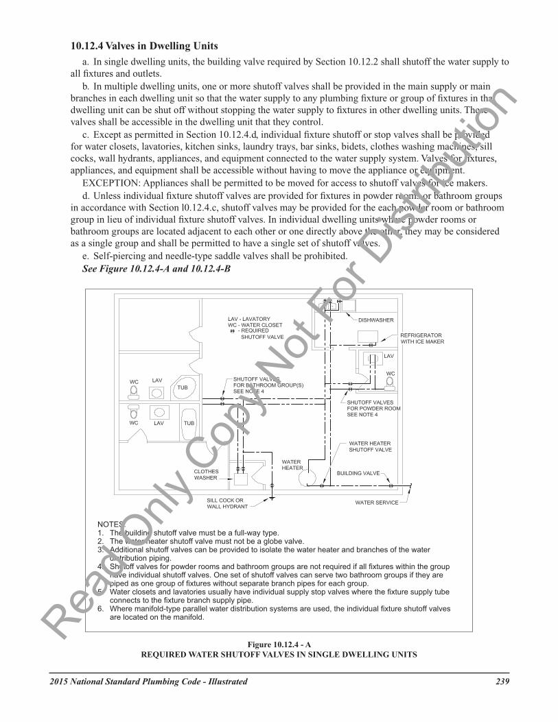
10.12.4 Valves in Dwelling Units
a. In single dwelling units, the building valve required by Section 10.12.2 shall shutoff the water supply to all fixtures and outlets.
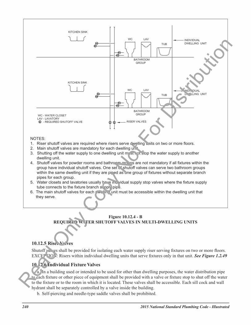
b. In multiple dwelling units, one or more shutoff valves shall be provided in the main supply or main branches in each dwelling unit so that the water supply to any plumbing fixture or group of fixtures in that dwelling unit can be shut off without stopping the water supply to fixtures in other dwelling units. These valves shall be accessible in the dwelling unit that they control.
c. Except as permitted in Section 10.12.4.d, individual fixture shutoff or stop valves shall be provided for water closets, lavatories, kitchen sinks, laundry trays, bar sinks, bidets, clothes washing machines, sill cocks, wall hydrants, appliances, and equipment connected to the water supply system. Valves for fixtures, appliances, and equipment shall be accessible without having to move the appliance or equipment.
EXCEPTION: Appliances shall be permitted to be moved for access to shutoff valves for ice makers.d. Unless individual fixture shutoff valves are provided for fixtures in powder rooms or bathroom groups
in accordance with Section l0.12.4.c, shutoff valves may be provided for the each powder room or bathroom group in lieu of individual fixture shutoff valves. In individual dwelling units where powder rooms or bathroom groups are located adjacent to each other or one directly above the other, they may be considered as a single group and shall be permitted to have a single set of shutoff valves.
e. Self-piercing and needle-type saddle valves shall be prohibited.See Figure 10.12.4-A and 10.12.4-B
Read O
nly C
opy N
ot Fo
r Dist
ributi
on
2015 National Standard Plumbing Code - Illustrated240
10.12.5 Riser Valves
Shutoff valves shall be provided for isolating each water supply riser serving fixtures on two or more floors. EXCEPTION: Risers within individual dwelling units that serve fixtures only in that unit. See Figure 1.2.49
10.12.6 Individual Fixture Valves
a. In a building used or intended to be used for other than dwelling purposes, the water distribution pipe to each fixture or other piece of equipment shall be provided with a valve or fixture stop to shut off the water to the fixture or to the room in which it is located. These valves shall be accessible. Each sill cock and wall hydrant shall be separately controlled by a valve inside the building.
b. Self-piercing and needle-type saddle valves shall be prohibited.
Read O
nly C
opy N
ot Fo
r Dist
ributi
on
2015 National Standard Plumbing Code - Illustrated 241
Comment: In buildings or portions thereof that are used for other than dwelling purposes, each fixture or equipment connection must have an individual shutoff means. Shutoff means in such systems cannot shutoff a group of fixtures that do not have individual shutoff means. The guest rooms in hotels and motels are considered to be dwelling units.
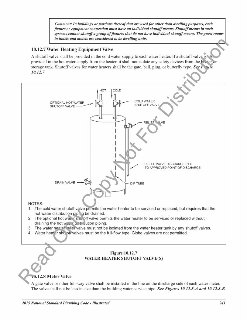
10.12.7 Water Heating Equipment Valve A shutoff valve shall be provided in the cold water supply to each water heater. If a shutoff valve is also provided in the hot water supply from the heater, it shall not isolate any safety devices from the heater or storage tank. Shutoff valves for water heaters shall be the gate, ball, plug, or butterfly type. See Figure 10.12.7
10.12.8 Meter Valve A gate valve or other full-way valve shall be installed in the line on the discharge side of each water meter. The valve shall not be less in size than the building water service pipe. See Figures 10.12.8-A and 10.12.8-B
240 2012 National Standard Plumbing Code - Illustrated
Comment: In buildings or portions thereof that are used for other than dwelling purposes, each fixture or equipment connection must have an individual shutoff means. Shutoff means in such systems cannot shutoff a group of fixtures that do not have individual shutoff means. The guest rooms in hotels and motels are considered to be dwelling units.
10.12.7 Water Heating Equipment Valve
A shutoff valve shall be provided in the cold water supply to each water heater. If a shutoff valve is also provided in the hot water supply from the heater, it shall not isolate any safety devices from the heater or storage tank. Shutoff valves for water heaters shall be the gate, ball, plug, or butterfly type. See Figure 10.12.7
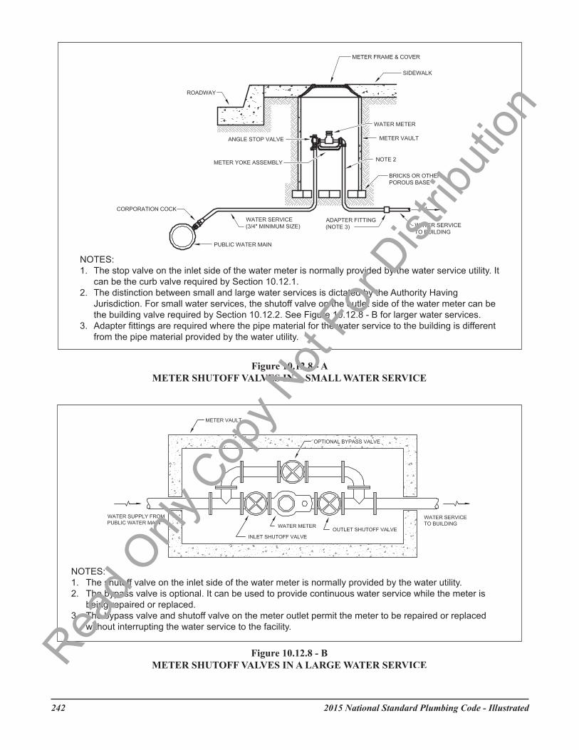
10.12.8 Meter Valve
A gate valve or other full-way valve shall be installed in the line on the discharge side of each water meter. The valve shall not be less in size than the building water service pipe. See Figures 10.12.8-A and 10.12.8-B
Read O
nly C
opy N
ot Fo
r Dist
ributi
on
2015 National Standard Plumbing Code - Illustrated242
Read O
nly C
opy N
ot Fo
r Dist
ributi
on
2015 National Standard Plumbing Code - Illustrated 243
10.12.9 Valve Accessibility
Water supply shutoff valves shall be placed so as to be accessible for use, service and maintenance.
Comment: Access to water supply shutoff valves can require the use of tools to remove access panels or doors.
10.13 FLEXIBLE WATER CONNECTORSFlexible water connectors exposed to continuous pressure shall conform to ASME A112.18.6/CSA B125.6. Access shall be provided to all flexible water connectors.
10.14 MINIMUM REQUIREMENTS FOR WATER DISTRIBUTION SYSTEMS
10.14.1 Maximum Velocity (See Appendix B.6)
Water distribution piping within buildings shall be sized for a maximum velocity of 8 feet per second at the design flow rate unless the pipe manufacturer’s sizing recommendations call for the maximum velocity to be less than 8 feet per second. The maximum velocity of hot water in copper tubing shall be 5 feet per second.
10.14.2 Size of Individual Fixture Supply Branches
a. Individual fixture supply branch pipe sizes shall be based on the minimum available flowing water pressure at the point of connection to the water distribution system, any elevation difference between that connection and the fixture, and the allowable pressure loss in the fixture supply branch. The minimum fixture supply branch pipe sizes shall be as indicated in Table 10.14.2A. For design purposes, the required pressure at each fixture inlet shall be 15 psig minimum with flow for all fixtures, except 20 psig flowing for flushometer valves on siphon jet water closets and 25 psig flowing for flushometer valves on blowout water closets and blowout urinals. Flushometer tank (pressure assisted) water closets require a minimum of 25 psig static pressure. The following water flow rates shall be used for the purpose of sizing individual fixture supply branch pipes:
5.0 gpm for hose bibbs and wall hydrants; 4.0 gpm for bath faucets and clothes washers; 0.75 gpm for drinking fountains and water coolers; 2.2 gpm for sink faucets; 2.5 gpm for showers; 2.2 gpm for lavatory faucets; 3.0 gpm for water closets other than the flushometer valve type; 12.0 gpm for flushometer valve urinals; 30.0 gpm for flushometer valve water closets
b. Fixture supply branches shall extend from the distribution system to within 30 inches of the point of connection to the fixture or device served and be within the same area and physical space as the point of connection to the fixture or device. Fixture supply tubes and flexible water connectors shall be not less than the size recommended by the manufacturer of the fixture, faucet, appliance or device served.
Read O
nly C
opy N
ot Fo
r Dist
ributi
on
2015 National Standard Plumbing Code - Illustrated244
Read O
nly C
opy N
ot Fo
r Dist
ributi
on
2015 National Standard Plumbing Code - Illustrated 245
Table 10.14.2A (continued) WATER SUPPLY FIXTURE UNITS (WSFU) AND
1/2” 2.5 2.5 2.5 Hose Bibb (each additional) 1/2” 1.0 1.0 1.0 Kitchen Sink, Domestic 1/2” 1.5 1.0 1.5 Laundry Sink 1/2” 2.0 1.0 2.0 Lavatory 3/8” 1.0 0.5 1.0 1.0 Service Sink or Mop Basin 1/2” 3.0 Shower 1/2” 2.0 2.0 2.0 Shower, continuous use 1/2” 5.0 Urinal, 1.0 GPF 3/4” 4.0 5.0 Urinal, greater than 1.0 GPF 3/4” 5.0 6.0 Wash Fountain (per rated user) 0.5 Wash Sink (1 or 2 faucets, per faucet) 1.0Wash Sink (additional faucets, per faucet) 0.5Water Closet, 1.6 GPF Gravity Tank 1/2” 2.5 2.5 2.5 4.0 Water Closet, 1.6 GPF Flushometer Tank 1/2” 2.5 2.5 2.5 3.5 Water Closet, 1.6 GPF Flushometer Valve 1” 5.0 5.0 5.0 8.0 Water Closet, 3.5 GPF Gravity Tank 1/2” 3.0 3.0 5.5 7.0 Water Closet, 3.5 GPF Flushometer Valve 1” 7.0 7.0 8.0 10.0 Whirlpool Bath or Combination Bath/Shower 1/2” 4.0 4.0
NOTES FOR TABLE 10.14.2A:1. A Bathroom Group, for the purposes of this Table, consists of not more than one water closet, up to two lavatories, and either one bathtub, one
bath/shower combination, or one shower stall. Other fixtures within the bathing facility shall be counted separately to determine the total water supply fixture unit load.
2. A Half-Bath or Powder Room, for the purposes of this Table, consists of one water closet and one lavatory.3. For unlisted fixtures, refer to a listed fixture having a similar flow and frequency of use.4. The listed fixture unit values for Bathroom Groups and Individual Fixtures represent their load on the cold water service. The separate cold water
and hot water fixture unit values for fixtures having both cold and hot water connections shall each be taken as 3/4 of the listed total value for the individual fixture.
5. When WSFU values are added to determine the demand on the water distribution system or portions thereof, round the sum to the nearest whole number before referring to Table 10.14.2B for the corresponding gallons per minute (gpm) flow. WSFU values of 0.5 or more should be rounded up to the next higher whole number (9.5 = 10 WSFU). Values of 0.4 or less should be rounded down to the next lower whole number (9.4 = 9 WSFU).
6. The listed minimum supply branch pipe sizes for individual fixtures are the nominal (I.D.) pipe size in inches.7. “Other Than Dwelling Units” applies to business, commercial, industrial, and assembly occupancies other than those defined under “Heavy-Use
Assembly.” Included are the public and common areas in hotels, motels, and multi-dwelling buildings.8. “Heavy-Use Assembly” applies to toilet facilities in occupancies that place heavy, but intermittent, time-based demands on the water supply
system, such as schools, auditoriums, stadiums, race courses, transportation terminals, theaters, and similar occupancies where queuing is likely to occur during periods of peak use.
9. For fixtures or supply connections likely to impose continuous flow demands, determine their required flow in gallons per minute (gpm) and add it separately to the demand (in gpm) for the distribution system or portion thereof.
Read O
nly C
opy N
ot Fo
r Dist
ributi
on
2015 National Standard Plumbing Code - Illustrated246
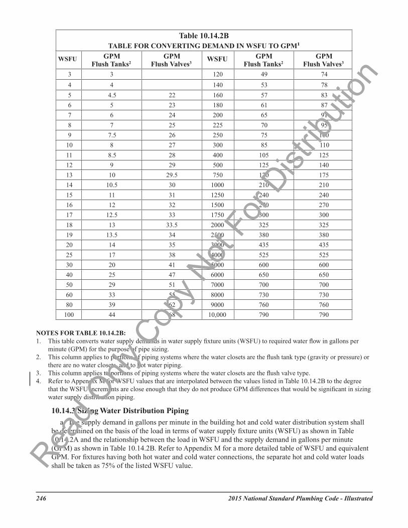
NOTES FOR TABLE 10.14.2B: 1. This table converts water supply demands in water supply fixture units (WSFU) to required water flow in gallons per minute (GPM)
for the purpose of pipe sizing. 2. This column applies to portions of piping systems where the water closets are the flush tank type (gravity or pressure) or there are no
water closets, and to hot water piping. 3. This column applies to portions of piping systems where the water closets are the flush valve type.
10.14.3 Sizing Water Distribution Piping a. The supply demand in gallons per minute in the building hot and cold water distribution system shall
be determined on the basis of the load in terms of water supply fixture units (WSFU) as shown in Table 10.14.2A and the relationship between the load in WSFU and the supply demand in gallons per minute (GPM) as shown in Table 10.14.2B. Refer to Appendix M for a more detailed table of WSFU and equivalent GPM. For fixtures having both hot water and cold water connections, the separate hot and cold water loads shall be taken as 75% of the listed WSFU value.
Table 10.14.2B TABLE FOR CONVERTING DEMAND IN WSFU TO GPM¹
2012 National Standard Plumbing Code - Illustrated 245
NOTES FOR TABLE 10.14.2B:1. This table converts water supply demands in water supply fixture units (WSFU) to required water flow in gallons per
minute (GPM) for the purpose of pipe sizing.2. This column applies to portions of piping systems where the water closets are the flush tank type (gravity or pressure) or
there are no water closets, and to hot water piping.3. This column applies to portions of piping systems where the water closets are the flush valve type.4. Refer to Appendix M for WSFU values that are interpolated between the values listed in Table 10.14.2B to the degree
that the WSFU increments are close enough that they do not produce GPM differences that would be significant in sizing water supply distribution piping.
10.14.3 Sizing Water Distribution Piping
a. The supply demand in gallons per minute in the building hot and cold water distribution system shall be determined on the basis of the load in terms of water supply fixture units (WSFU) as shown in Table 10.14.2A and the relationship between the load in WSFU and the supply demand in gallons per minute (GPM) as shown in Table 10.14.2B. Refer to Appendix M for a more detailed table of WSFU and equivalent GPM. For fixtures having both hot water and cold water connections, the separate hot and cold water loads shall be taken as 75% of the listed WSFU value.Rea
d Only
Cop
y Not
For D
istrib
ution
2015 National Standard Plumbing Code - Illustrated 247
b. Main risers and branches of the water distribution system shall be sized based on the minimum available water pressure at the source, any elevation differences between the source and the fixtures, pressure losses in the distribution system, and the pressure (with flow) required at each connection to the fixture supply branches. See Section 10.14.2.
10.14.4 Inadequate Water Pressure
Whenever water pressure from the street main or other sources of supply is insufficient to provide flow pressures at fixture outlets as required under Section 10.14.2, a booster pump and pressure tank or other approved means shall be installed on the building water supply system.
10.14.5 Variable Street Pressures
Where street water main pressures fluctuate, the building water distribution system shall be designed for the minimum pressure available.
10.14.6 Excessive Pressures
a. Pressure reducing valves complying with ASSE 1003 shall be provided if required to limit the water supply pressure at any fixture appliance, appurtenance, or outlet to not more than 80 psi under no-flow conditions.
b. The requirement of Section 10.14.6.a above shall not prohibit supply pressures higher than 80 psi from water pressure booster systems under Section 10.14.4 or in high pressure distribution systems, provided that the pressure at the fixtures served is subsequently reduced to 80 psi maximum. Where operating water pressures exceed 80 psi, the working pressure rating of materials and equipment shall be suitable for the maximum pressure that may be encountered, including temporary increases or surges.
c. Where pressure reducing valves are installed and the downstream piping is not rated for the maximum upstream pressure, a pressure relief valve shall be installed downstream from the pressure reducing valve. The relief valve shall be set not higher than the working pressure rating of the downstream piping and sized for not less than the flow capacity of the pressure reducing valve. Relief valves shall discharge in accordance with Section 10.16.6.
d. When a pressure reducing valve is installed, a gauge port or pressure gauge with pressure range of 0-150 psi shall be installed within 24 inches downstream from the reducing valve.
EXCEPTION: In dwelling units, gauge ports or pressure gauges shall not be required if there is a hose bibb or hose-end drain valve to which a pressure test gauge can be connected.See Figures 10.14.6-A and 10.14.6-B
Read O
nly C
opy N
ot Fo
r Dist
ributi
on
2015 National Standard Plumbing Code - Illustrated248
SHUTOFF VALVE
SUPPLY PRESSURE GREATER THAN 80 psi
SUPPLY PRESSURE TO FIXTURES REDUCED TO 80 psi MAX
PRESSURE RELIEF VALVE (if required)
PRESSURE REDUCING VALVE
TO APPROVED POINT OF DISCHARGE
Read O
nly C
opy N
ot Fo
r Dist
ributi
on
2015 National Standard Plumbing Code - Illustrated 249
10.14.7 Water Hammer
a. Approved water hammer arresters, complying with ASSE 1010 or PDI WH 201 shall be installed on water distribution piping in which quick closing valves are installed.
EXCEPTION: Single lever faucets, domestic clothes washers, and domestic dishwashers.b. Water hammer arresters shall be placed as close as possible to the quick acting valve, at the end of long
piping runs, or near batteries of fixtures.c. Arresters shall be accessible for replacement.
See Figure 10.14.7Read O
nly C
opy N
ot Fo
r Dist
ributi
on
2015 National Standard Plumbing Code - Illustrated250
10.15 HOT WATER
10.15.1 Hot Water Supply System
In residences and buildings intended for human occupancy, hot water shall be supplied to all plumbing fixtures, appliances, and equipment that require hot water for their use. EXCEPTION: In buildings other than dwelling units, tempered water supply systems shall be permitted to supply fixtures that deliver only tempered water.
10.15.2 Temperature Maintenance Where Required
a. Where the developed length of the hot water supply piping exceeds 100 feet from the hot water source to the farthest hot water outlet, the system shall maintain the temperature of the hot water to within 25 feet developed length from every hot water outlet served.
b. Where required by Section 10.15.2.a, the hot water temperature within the piping shall be maintained by heat tracing or recirculation of the hot water. The temperature of the hot water in the piping shall be maintained by automatic controls with manual auto-off.
c. The requirements of this section for temperature maintenance also apply to tempered water supply piping. See Figure 10.15.2
Figure 10.14.7WATER HAMMER ARRESTORS
Read O
nly C
opy N
ot Fo
r Dist
ributi
on
2015 National Standard Plumbing Code - Illustrated 251
Figure 10.15.2 HOT WATER TEMPERATURE MAINTAINENCE BY RECIRCULATION
10.15.3 Minimum Requirements for Hot Water Storage Tanks a. Hot water storage tanks shall be adequate in size, when combined with the BTUH input of the water
heating equipment, to provide the rise in temperature necessary. b. Water heaters and storage tanks shall be sized to provide sufficient hot water to provide both daily
requirements and hourly peak loads of the occupants of the building. c. Storage tanks shall be protected against excessive temperatures and pressure conditions as specified in
this Code. (See Sections 3.3.8 and 3.3.10)
10.15.4 Drainage of Hot Water Storage Tanks Hot water storage tanks shall be equipped with a valve capable of draining the tank completely. See Figure 10.12.7
10.15.5 Pressure Marking of Hot Water Storage Tanks Hot water storage tanks shall be permanently marked in an accessible place with the maximum allowable working pressure, in accordance with the applicable standard as listed in Table 3.1.3.
250 2012 National Standard Plumbing Code - Illustrated
10.15.3 Minimum Requirements for Hot Water Storage Tanks
a. Hot water storage tanks shall be adequate in size, when combined with the BTUH input of the water heating equipment, to provide the rise in temperature necessary.
b. Water heaters and storage tanks shall be sized to provide sufficient hot water to provide both daily requirements and hourly peak loads of the occupants of the building.
c. Storage tanks shall be protected against excessive temperatures and pressure conditions as specified in this Code. (See Sections 3.3.8 and 3.3.10)
10.15.4 Drainage of Hot Water Storage Tanks
Hot water storage tanks shall be equipped with a valve capable of draining the tank completely.See Figure 10.12.7
10.15.5 Pressure Marking of Hot Water Storage Tanks
Hot water storage tanks shall be permanently marked in an accessible place with the maximum allowable working pressure, in accordance with the applicable standard as listed in Table 3.1.3.Rea
d Only
Cop
y Not
For D
istrib
ution
2015 National Standard Plumbing Code - Illustrated252
10.15.6 Mixed Water Temperature Control
a. Hot Water Supply Sources: The temperature control devices for water heaters and other hot water supply sources shall not be permitted to be used to meet this Section’s requirements for mixed water temperature control.
b. Hot Water Distribution Temperature Control: Where temperature-actuated mixing valves are installed to control the hot water supply temperature in the water distribution system, they shall comply with ASSE 1017. Such devices shall be installed at the hot water source and alone shall not supersede the other requirements of Section 10.15.6 for mixed water temperature control.
c. Application of Water Temperature Control and Limiting Devices: The inlet hot and cold water temperatures for temperature control and limiting devices shall be within their operating ranges and have sufficient differential above and below their discharge set point.
d. Where Check Valves Are Required: Where a water temperature control control or temperature limiting device supplies one or more outlets that can be shutoff downstream from the device, the device shall include integral check valves or check valves shall be provided in the hot and cold water supplies to the device or at its inlets to prevent cross flow through the device when there is no flow through the outlet or outlets that it supplies.
e. Showers and Bath/Shower Combinations: The water discharged from shower heads, wall or ceiling mounted hand held showers, body sprays, and tub spouts shall be controlled to a temperature no higher than 120ºF by a Type P, Type T, or Type P/T automatic compensating valve complying with ASME A112.1016/ASSE 1016/CSA B125.16.
f. Multiple Showers: Where multiple (gang) showers are supplied by a one pipe tempered water supply system, the water temperature shall be controlled to a temperature no higher than 105ºF by an automatic temperature control mixing valve complying with ASSE 1069.
g. Multiple Lavatories: Where multiple lavatories are supplied by a one-pipe tempered water supply system, the water temperature shall be controlled to a temperature no higher than 110ºF by a water temperature limiting device complying with ASSE 1070 or CSA B125.3.
h. Bathtubs and Whirlpool Baths: The hot water supply to the faucets for bathtubs and whirlpool baths without showers and with or without deck-mounted hand sprays, shall be controlled to a temperature no higher than 120°F by a water temperature limiting device complying with ASSE 1070 or CSA B125.3. EXCEPTION: A water temperature limiting device shall not be required if the fixture is supplied by an ASSE 1016 automatic compensating valve.
i. Bidets: The hot water supply to the faucet on bidet plumbing fixtures shall be controlled to a temperature no higher than 110°F by a water temperature limiting device complying with ASSE 1070 or CSA B125.3. Where bidets are incorporated into toilet seats or consist of a heated water tank and nozzle, their controls shall limit the discharge temperature to no more than 110°F.
j. Hand Washing Facilities: The hot water supply to the following hand washing fixtures shall be controlled to a temperature no higher than 110ºF by a water temperature limiting device complying with ASSE 1070 or CSA B125.3:
1. in public toilet rooms 2. in hotel and motel guest rooms 3. in hospital patient rooms 4. in medical and clinical treatment rooms 5. wash fountains 6. wash sinks k. Commercial Hair/Shampoo Sink Sprays: The hot water supply to the faucets and controls for
commercial hair/shampoo sink sprays and pedicure basins shall be limited to a temperature no higher than 110°F by a temperature limiting device complying with ASSE 1070 or CSA B125.3.
l. Animal Washing Fixtures: The hot water supply to the faucet or control device for an animal washing fixture shall be controlled to a temperature no higher than 110°F by a temperature limiting device complying with ASSE 1070 or CSA B125.3.
Read O
nly C
opy N
ot Fo
r Dist
ributi
on
2015 National Standard Plumbing Code - Illustrated 253
m. Temperature Actuated Flow Reduction (TAFR) Devices: Where temperature actuated flow reduction (TAFR) devices are installed to limit the maximum mixed water temperature to 120°F for individual fixture fittings, such devices shall comply with ASSE 1062. These devices shall not supersede the other requirements of Section 10.15.6.
n. In-Line Pressure Balancing Valves: Where in-line pressure balancing valves are installed to compensate for water pressure fluctuations to stabilize the temperature discharges from their individual faucet or fixture fitting, such devices shall comply with ASSE 1066. These devices shall be installed in an accessible location and alone shall not supersede the other requirements of Section 10.15.6.
o. Devices installed for mixed water temperature control, temperature limiting, flow reduction, or pressure balance shall be field-adjusted in accordance with the manufacturer’s instructions.
10.15.7 Thermal Expansion Control
a. Where a water pressure regulator (with or without an internal thermal expansion bypass), a backflow preventer, or a check valve is installed such that a closed system is created to the water supply source for the hot water heating equipment, a device for controlling thermal expansion shall be provided. EXCEPTIONS: (1) Instantaneous water heaters. (2) Well systems with water pressure tanks.
b. Thermal expansion tanks shall be the adjustable pre-charged type for potable water, steel construction with a flexible bladder or bellows, rated for not less than 125 psig and 200ºF, and sized to limit the increased water system pressure to no higher than 100 psig. Tanks shall be sized and installed in accordance with the manufacturer’s instructions.
c. Thermal expansion control devices shall be connected to the water supply piping between the hot water heating equipment and its shutoff valve.
10.15.8 Plastic Piping
a. Plastic piping used for hot water distribution shall conform to the requirements of Section 3.4.3 and Table 3.4.3. Piping shall be water pressure rated for not less than 100 psi at 180ºF and 160 psi at 73º.
NOTE: The working pressure rating for certain approved plastic piping materials varies depending on material composition, pipe size, wall thickness and method of joining. See Table 3.4.3.
b. Plastic pipe or tube shall not be used downstream from instantaneous water heaters, immersion water heaters or other heaters not having approved temperature safety devices.
c. Piping within six inches of flue or vent connectors shall be approved metallic pipe or tube.d. The normal operating pressure in water distribution piping systems utilizing approved plastic pipe or
tube for hot water distribution shall be not more than 80 psi. Where necessary, one or more pressure reducing valves shall be provided to regulate the hot and cold water supply pressure to not more than 80 psi.
e. The pressure in the hot water distribution piping shall be limited by a pressure relief valve set no higher than 150 psi. When the water heater is protected by a pressure relief valve or combination pressure temperature relief valve having a pressure setting higher than 150 psi, a separate pressure relief valve shall be provided to protect the piping. The relief valve for the piping shall comply with Section 10.16.2 except that it shall be set no higher than 150 psi. Thermal expansion shall be controlled as required under Section 10.15.7.
10.15.9 Drip Pans
10.15.9.1 Where Required
Where tank-type water heaters or hot water storage tanks are installed in locations where leakage will cause structural damage to the building, the tank or water heater shall be installed in a drip pan in accordance with Section 10.15.9.2 and 10.15.9.3.
10.15.9.2 Construction
a. Drip pans shall be watertight and constructed of corrosion-resistant materials. Galvanized steel pans shall be 24 gauge (0.0276-inch) minimum thickness. Aluminum pans shall be 20 gauge (0.0320-inch) minimum thickness. Non-metallic pans shall be 0.0625-inch minimum thickness. Pans shall be not less than 1-1/2'' deep but shall not be deeper than the bottom of the water heater tank or hot
Read O
nly C
opy N
ot Fo
r Dist
ributi
on
2015 National Standard Plumbing Code - Illustrated254
water storage tank. They shall be of sufficient size to hold the heater or tank without interfering with drain valves, burners, controls, and any required access.
b. High impact plastic pans shall be permitted under gas-fired water heaters where the heater is listed for zero clearance for combustible floors and the application is recommended by the pan manufacturer.
10.15.9.3 Drainage
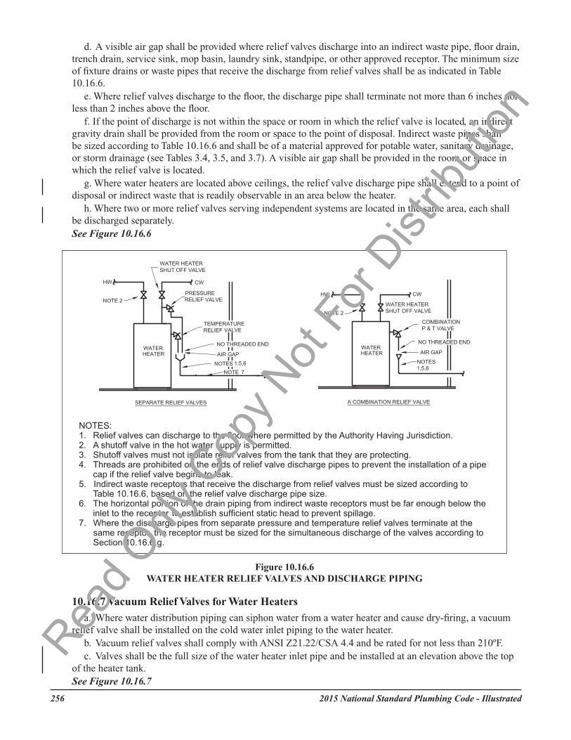
a. Drip pans shall have drain outlets not less than 3/4" size, with drain pipes extending to an approved point of discharge, a suitably located indirect waste receptor, or to within 2 to 6 inches above the adjacent floor.
b. Discharge from a relief valve into a water heater drip pan shall be permitted if the drain size for the drip pan is not less than the relief valve discharge pipe size and the discharge pipe extends to within 2 to 6 inches above the bottom of the pan.
c. For drip pans installed under water heaters that are located above ceilings, the drain pipe from the drip pan shall extend to a point of disposal or indirect waste that is readily observable in an area below the heater.
10.15.10 Water Heaters Used for Space Heating
a. Water heaters used for space heating shall be listed for such use.b. Piping and components connected to a water heater for space heating application shall be suitable for
use with potable water.c. Where required, a water temperature control valve shall be installed in every combination water/space
heating system application to limit domestic hot water temperature to 140°F. The temperature control device shall be an ASSE 1017 listed device.
10.15.11 Water Heaters
a. Water heaters shall be applied, sized, and installed in accordance with the manufacturer’s recommendations and instructions.
b. Gas-fired storage tank water heaters with input ratings of 75,000 Btuh or less shall comply with ANSI Z21.10.1/CSA 4.1.
c. Gas-fired storage tank water heaters with input ratings above 75,000 Btuh shall comply with ANSI Z21.10.3/CSA 4.3.
d. Gas-fired tankless water heaters shall comply with ANSI Z21.10.3/CSA 4.3. e. Oil-fired storage tank water heaters shall comply with UL 732. f. Household electric storage tank water heaters up to 120 gallons and 12 KW capacity shall comply with
UL 174. g. Commercial electric storage tank water heaters over 120 gallons and 12 KW capacity shall comply with
UL 1453. h. Tankless electric water heaters shall comply with UL 499.
Comment: Tankless water heaters include whole-home, multi-fixture, and point-of-use heaters.
10.16 SAFETY DEVICES FOR PRESSURE VESSELS
10.16.1 Tank Protection
a. Pressure vessels used for heating water or storing water at pressures above atmospheric shall be protected by approved safety devices in accordance with one of the following methods:
1. A separate pressure relief valve and a separate temperature relief valve; or2. A combination pressure and temperature relief valve; or3. Either “1” or “2” above and an energy cut-off device.
Read O
nly C
opy N
ot Fo
r Dist
ributi
on
2015 National Standard Plumbing Code - Illustrated 255
4. Tank construction conforming to a standard that does not require a temperature or pressure safety or relief valve.
Comment: If a pressure relief valve, temperature relief valve, or combination pressure/ temperature relief valve is installed for a water heater storage tank, there must not be any shutoff valves between the relief valve(s) and the tank that they protect. Also, there must not be any shutoff valves in any relief valve discharge piping.
10.16.2 Pressure Relief Valves
a. Pressure relief valves shall comply with the applicable standards listed in Table 3.1.3.b. The valves shall have a relief setting of not more than the pressure rating of the tank, or 150 psig
maximum, and shall be installed either directly in a tank tapping or in the hot or cold water piping close to the tank. Pressure relief valves installed in hot water piping shall be rated not less than 180 degrees F.
c. There shall be no shutoff valve between the pressure relief valve and the tank.d. The pressure relief valve shall be set to open at not less than 25 psig above the street main pressure or
not less than 25 psig above the setting of any building water pressure regulating valve.See Figure 10.16.6
10.16.3 Temperature Relief Valves
a. Temperature relief valves shall have an adequate relief rating, expressed in BTU/HR, for the equipment served.b. The CSA temperature steam rating shall be used when a water heater has a heat input rating of 200,000
BTU/HR or less, a water temperature of 210ºF or less, a nominal water-containing capacity of 120 gallons or less, is not ASME rated, and does not exhibit an ASME “HLW” symbol or a National Board “NB” number.
c. The ASME pressure steam rating shall be used if a water heater is ASME rated and exhibits an ASME “HLW” symbol or a National Board “NB” number.
d. The valves shall be installed so that the temperature sensing element is in the hottest water within the top 6 inches of the tank.
e. The valves shall be set to open when the stored water temperature reaches a maximum of 210ºF. (See Section 3.3.10.)
f. The valves shall conform to an approved standard and shall be sized so that when the valve opens, the water temperature cannot exceed 210ºF with the water heating equipment operating at maximum input. See Figure 10.16.6
Combination pressure-temperature relief valves shall comply with all the requirements of the separate pressure and temperature relief valves. See Sections 10.16.2 and 10.16.3
10.16.5 Reserved
10.16.6 Relief Valve Piping
a. There shall be no shut-off valve, check valve, or other restricting device between a relief valve and the pressure vessel or piping system being protected.
b. Piping from the outlet of a relief valve to the point of disposal shall be of a material suitable for potable water (see Section 3.4). Discharge pipes from temperature relief valves and combination pressure- temperature relief valves shall be listed in Table 3.4 for hot water distribution, and shall be suitable for conveying water at 210°F to an open discharge. The pressure rating of the pipe at 210 deg F is not required to equal or exceed the pressure setting of the relief valve.
c. The discharge pipe shall be no smaller than the outlet size of its relief valve and shall extend to a point of disposal without valves, traps, or rises that would prevent the discharge piping from draining by gravity. The discharge end of the pipe shall not be threaded.Rea
d Only
Cop
y Not
For D
istrib
ution
2015 National Standard Plumbing Code - Illustrated256
d. A visible air gap shall be provided where relief valves discharge into an indirect waste pipe, floor drain, trench drain, service sink, mop basin, laundry sink, standpipe, or other approved receptor. The minimum size of fixture drains or waste pipes that receive the discharge from relief valves shall be as indicated in Table 10.16.6.
e. Where relief valves discharge to the floor, the discharge pipe shall terminate not more than 6 inches nor less than 2 inches above the floor.
f. If the point of discharge is not within the space or room in which the relief valve is located, an indirect gravity drain shall be provided from the room or space to the point of disposal. Indirect waste pipes shall be sized according to Table 10.16.6 and shall be of a material approved for potable water, sanitary drainage, or storm drainage (see Tables 3.4, 3.5, and 3.7). A visible air gap shall be provided in the room or space in which the relief valve is located.
g. Where water heaters are located above ceilings, the relief valve discharge pipe shall extend to a point of disposal or indirect waste that is readily observable in an area below the heater.
h. Where two or more relief valves serving independent systems are located in the same area, each shall be discharged separately. See Figure 10.16.6
10.16.7 Vacuum Relief Valves for Water Heaters
a. Where water distribution piping can siphon water from a water heater and cause dry-firing, a vacuum relief valve shall be installed on the cold water inlet piping to the water heater.
b. Vacuum relief valves shall comply with ANSI Z21.22/CSA 4.4 and be rated for not less than 210ºF.c. Valves shall be the full size of the water heater inlet pipe and be installed at an elevation above the top
of the heater tank.See Figure 10.16.7
Read O
nly C
opy N
ot Fo
r Dist
ributi
on
2015 National Standard Plumbing Code - Illustrated 257
10.16.6 Relief Valve Discharge Piping a. Piping from the outlet of a relief valve to the point of disposal shall be of a material suitable for potable
water (see Section 3.4). Discharge pipes from temperature relief valves and combination pressure- temperature relief valves shall be listed in Table 3.4 for hot water distribution, and shall be suitable for conveying water at 210°F to an open discharge. The pressure rating of the pipe at 210 deg F is not required to equal or exceed the pressure setting of the relief valve.
b. There shall be no shut-off valve, check valve or other restricting device between a relief valve and the pressure vessel or piping system being protected.
c. The discharge end of the pipe shall be no smaller than the outlet size of its relief valve and shall extend to a point of disposal without valves, traps or rises that would prevent the discharge piping from draining by gravity. The discharge end of the pipe shall not be threaded.
d. An air gap shall be provided where relief valves discharge into an indirect waste pipe, floor drain, trench drain, service sink, mop basin, laundry sink, standpipe or other approved receptor. The minimum size of fixture drains or waste pipes that receive the discharge from relief valves shall be as indicated in Table 10.16.6.
e. Where relief valves discharge to the floor, the discharge pipe shall terminate not more than 6 inches nor less than 2 inches above the floor.
f. If the point of disposal is not within the space or room in which the relief valve is located, an indirect gravity drain shall be provided from the room or space to the point of disposal. Indirect waste pipes shall be sized according to Table 10.16.6 and shall be of a material approved for potable water, sanitary drainage or storm drainage (see Tables 3.4, 3.5, and 3.7). A visible air gap shall be provided in the room or space in which the relief valve is located.
EXCEPTION: Where water heaters are located above ceilings, the relief valve discharge pipe shall extend to a point of disposal or indirect waste that is readily observable in an area below the heater.
g. Where two or more relief valves serving independent systems are located in the same area, each shall be discharged separately. Where such relief valves for independent systems are discharged into a common gravity drain or indirect waste pipe, the drain or waste pipe shall be sized according to the largest discharge pipe served. See Figure 10.16.6
*EXCEPTION: A laundry sink with 1-1/2” waste pipe.
10.16.7 Vacuum Relief Valves for Water Heaters a. Where water distribution piping can siphon water from a water heater and cause dry-firing, a vacuum
relief valve shall be installed on the cold water inlet piping to the water heater. b. Vacuum relief valves shall comply with ANSI Z21.22 and be rated for not less than 210°F. c. Valves shall be the full size of the water heater inlet pipe and be installed at an elevation above the top
of the heater tank. See Figure 10.16.7
Table 10.16.6 SIZE OF DRAINS OR WASTE PIPES RECEIVING RELIEF VALVE DISCHARGE
Discharge Pipe Size Minimum Drain or Indirect Waste Size
3/4” 2”* 1” 3”
1-1/2” 4” 2” 4”
2-1/2” 6”
2012 National Standard Plumbing Code - Illustrated 255
10.16.8 Replacement of Relief Valves a. Relief valves shall be maintained in proper working order and shall be replaced when necessary.b. Whenever a water heater is replaced, its temperature relief valve and pressure relief valve, or
combination temperature-pressure relief valve shall also be replaced and shall not be reused.
10.17 MANIFOLD-TYPE PARALLEL WATER DISTRIBUTION SYSTEMS
10.17.1 General a. Parallel water distribution systems shall provide individual hot and cold water supply lines from a
manifold to each fixture served. b. Manifolds shall be specifically designed and manufactured for parallel water distribution.c. Manufacturer’s of such systems shall provide complete sizing and installations instructions, including
any limitations or restrictions on use. d. Piping materials shall be as recommended by the system manufacturer and be listed in Table 3.4 for hot
and cold water distribution.
10.17.2 Sizing See Appendix B for sizing manifolds and distribution lines. Distribution line sizes shall be as recommended by the system manufacturer to provide the fixture flow rates listed in Section 10.14.2a. The minimum line size shall be 3/8” nominal.
Figure 10.16.7 VACUUM RELIEF VALVES ON OVERHEAD WATER HEATER TANKS
256 2012 National Standard Plumbing Code - Illustrated
2"-6"2"-6"
10.16.8 Replacement of Relief Valves
a. Relief valves shall be maintained in proper working order and shall be replaced when necessary.b. Whenever a water heater is replaced, its temperature relief valve and pressure relief valve, or
combination temperature-pressure relief valve shall also be replaced and shall not be reused.
Read O
nly C
opy N
ot Fo
r Dist
ributi
on
2015 National Standard Plumbing Code - Illustrated258
10.17 MANIFOLD-TYPE PARALLEL WATER DISTRIBUTION SYSTEMS
10.17.1 General
a. Parallel water distribution systems shall provide individual hot and cold water supply lines from a manifold to each fixture served.
b. Manifolds shall be specifically designed and manufactured for parallel water distribution.c. Manufacturer’s of such systems shall provide complete sizing and installations instructions, including
any limitations or restrictions on use.d. Piping materials shall be as recommended by the system manufacturer and be listed in Table 3.4 for hot
and cold water distribution.
10.17.2 Sizing
See Appendix B.12 for sizing manifolds and distribution lines. Distribution line sizes shall be as recommended by the system manufacturer to provide the fixture flow rates listed in Section 10.14.2.a. The minimum line size shall be 3/8" nominal.
10.17.3 Valving
a. Each manifold outlet that is equipped with a shutoff valve shall identify the fixture being supplied. Additional shut-off or stop valves at the fixtures shall be provided as required by Section 10.12.4.2.a.
EXCEPTION: Additional shut-off or stop valves at the fixtures shall not be required if a manifold with shutoff valves is located within the same room as the fixtures, or in an adjacent closet.
b. Manifolds having shutoff valves shall be readily accessible.
10.17.4 Support
a. Tube bundles for manifold systems shall be supported in accordance with Chapter 8 of this Code.b. Supports at changes in direction shall be in accordance with the system manufacturer’s
recommendations.
10.17.5 Combined Distribution Systems
Manifold-type parallel water distribution systems shall be permitted to be combined with conventional main/branch piping systems that serve one or more fixture(s) through common main and branch piping.
10.18 DRINKING WATER TREATMENT UNITS
10.18.1 Compliance with Standards
Drinking water treatment units shall comply with the appropriate standards listed below. a. NSF 42 Drinking Water Treatment Units - Aesthetic Effects b. NSF 44 Water Softeners (cation exchange) c. NSF 53 Drinking Water Treatment Units - Health Effects d. NSF 55 Ultraviolet Microbiological Water Treatment Systems e. NSF 58 Reverse Osmosis Drinking Water Systems f. CSA B483.1 Drinking Water Treatment Systems
Read O
nly C
opy N
ot Fo
r Dist
ributi
on
2015 National Standard Plumbing Code - Illustrated 259
10.17.3 Valving a. Each manifold outlet that is equipped with a shutoff valve shall identify the fixture being supplied.
Additional shut-off or stop valves at the fixtures shall be provided as required by Section 10.12.4. EXCEPTION: Additional shut-off or stop valves at the fixtures shall not be required if a manifold with
shutoff valves is located within the same room as the fixtures, or in an adjacent closet. b. Manifolds having shutoff valves shall be readily accessible.
10.17.4 Support a. Tube bundles for manifold systems shall be supported in accordance with Chapter 8 of this Code. b. Supports at changes in direction shall be in accordance with the system manufacturer’s
recommendations.
10.17.5 Combined Distribution Systems Manifold-type parallel water distribution systems shall be permitted to be combined with conventional main/branch piping systems that serve one or more fixture(s) through common main and branch piping.
10.18 DRINKING WATER TREATMENT UNITS
10.18.1 Compliance with Standards Drinking water treatment units shall comply with the standards listed in Table 3.1.3.
10.18.2 Air Gap Discharge Discharge from all drinking water treatment units shall be installed with an air gap. EXCEPTION: Reject water connections from reverse osmosis drinking water treatment units shall be through an air gap or alternate air gap device in accordance with the requirements of NSF 58.
10.18.3 Connection Tubing The tubing to and from the drinking water treatment unit shall be of a size and material as recommended by the manufacturer. The tubing shall comply with NSF 14, NSF 58 or NSF 61.
10.19 SIZING OF RESIDENTIAL WATER SOFTENERS
Residential-use water softeners shall be sized per Table 10.19.
NOTES FOR TABLE 10.19¹ Installation with a kitchen sink and dishwasher, laundry tray and automatic clothes washer. ² An additional water closet and lavatory shall be permitted without an increase in sizing. ³ Over four Bathroom Groups, the softener shall be engineered for the specific installation.
Table 10.19 SIZING OF RESIDENTIAL WATER SOFTENERS
Required Size of Softener Connection (in.) Number of Bathroom Groups Served1
3/4 Up to 22
1 Up to 43
2012 National Standard Plumbing Code - Illustrated 257
10.19 SIZING OF RESIDENTIAL WATER SOFTENERSResidential-use water softeners shall be sized per Table 10.19.
NOTES FOR TABLE 10.19:1. The number of bathroom groups served may include a kitchen sink, dishwasher, laundry sink, and automatic clothes washer.2. An additional water closet and lavatory shall be permitted without an increase in sizing.3. Over four Bathroom Groups, the softener shall be engineered for the specific installation.
10.20 NFPA 13D MULTIPURPOSE RESIDENTIAL FIRE SPRINKLER SYSTEMS
10.20.1 Where Permitted
NFPA 13D multipurpose residential fire sprinkler systems shall be permitted where approved by the Authority Having Jurisdiction for plumbing under this Code and by the Authority Having Jurisdiction for fire protection systems.
10.20.2 General
a. The plumbing requirements for NFPA 13D multipurpose residential fire sprinkler piping systems, which provide both domestic cold water distribution and fire sprinkler protection for one- and two-family dwellings from a combination piping system, shall comply with the applicable requirements of this Code.
b. The fire protection requirements for NFPA 13D multipurpose residential fire sprinkler systems shall comply with the requirements of NFPA 13D and the Authority Having Jurisdiction for fire protection systems.
c. NFPA 13D multipurpose piping systems include network systems where each fire sprinkler is supplied from at least three separate paths.
d. NFPA 13D piping systems shall not be multipurpose if they require the use of antifreeze.e. NFPA 13D multipurpose piping systems shall not include domestic hot water distribution to plumbing
fixtures. Piping for domestic hot water distribution shall comply with Section 3.4.3.f. The design of the plumbing portions of NFPA 13D multipurpose piping systems shall comply with the
requirements of this Code. g. The design of the fire sprinkler portions of NFPA 13D multipurpose piping systems shall comply with
the requirements of NFPA 13D. h. The installation of the plumbing portions of NFPA 13D multipurpose piping systems, which consist
of the water supply to the multipurpose system and the branch piping that supplies cold water to plumbing fixtures and end-use devices, shall be performed under the plumbing permit issued by the Authority Having Jurisdiction for plumbing.
i. The installation of the fire sprinkler portions of NFPA 13D multipurpose piping systems, which consist of the fire sprinklers and their supply piping, shall be performed under the fire sprinkler permit issued by the Authority Having Jurisdiction for fire sprinkler systems.
Read O
nly C
opy N
ot Fo
r Dist
ributi
on
2015 National Standard Plumbing Code - Illustrated260
10.20.3 Water Supply
a. The water supply to an NFPA 13D multipurpose piping system shall:1. not include a fire department connection.2. not include an alternate supply of non-potable water.3. not require a backflow prevention device.
b. A single shutoff valve shall be provided to shutoff the water supply to the multipurpose piping system and the cold water supply to the domestic hot water source for the plumbing fixtures served with cold water by the multipurpose piping system. Separate shutoff valves shall be provided for plumbing fixtures beyond the multipurpose piping as required by Section 10.12.4.
10.20.4 Materials for Combined System Piping
a. Piping materials shall be in accordance with this Section and be listed, as defined in NFPA 13D, for both residential fire sprinkler service and potable water distribution.
b. Copper piping shall be ASTM B88 copper water tube, Type L or K. Fittings shall be the solder joint type, ASME B16.22 wrought or ASME B16.18 cast. Solder shall comply with ASTM B32. Flux shall comply with ASTM B813. Solder and flux shall contain no more than 0.2% lead. Soldered joints shall comply with ASTM B828.
c. Plastic piping shall be CPVC or PEX in accordance with Table 3.4.3. Plastic piping shall be rated for 160 psig at 73 deg F, 130 psig at 120 deg F, and 100 psig at 180 deg F.
10.20.5 Pipe Sizing
a. Piping shall be sized to satisfy the fire sprinkler requirements of NFPA 13D and the domestic water distribution requirements of this Code.
b. The pipe sizing for fire sprinkler performance shall include 4 GPM of domestic water flow. The 4 GPM of domestic water flow shall be to any single clothes washer connection or exterior hose bibb that is in the path of the design sprinkler water flow.
c. After the pipe sizing is established for fire sprinkler performance, the sizing of the piping shall be increased if necessary for domestic water distribution with no demand for fire sprinkler flow.
d. The minimum pipe size for combination piping shall be 3/4" except where NFPA 13D permits 1/2" pipe size in network systems. The minimum pipe size for individual plumbing outlets shall be in accordance with Section 10.14.2.
10.20.6 System Flushing
a. Multipurpose piping shall be flushed in accordance with Section 10.9.1 through each plumbing outlet that it serves.
b. Multipurpose piping shall not be disinfected.
10.20.7 Warning: Signs
In accordance with NFPA 13D, a warning sign for the multipurpose piping system shall be installed at the main building water shutoff valve and at any other valves that will shutoff the water supply to the fire sprinkler system.
Read O
nly C
opy N
ot Fo
r Dist
ributi
on
2015 National Standard Plumbing Code - Illustrated 261
10.21 NON-POTABLE WATER PIPINGa. Where non-potable water distribution systems are installed for irrigation, flushing water closets or urinals, or
other non-potable water use in typical potable water applications, the following shall apply:1. The use of non-potable water shall be approved by the Authority Having Jurisdiction.2. The piping shall comply with Section 3.4 for potable water.3. Non-potable water piping shall be visibly identified to differentiate it from potable water piping.4. Non-potable water pipe may be purple colored.5. Potable water pipe shall not be purple colored.
b. Non-potable water piping shall be identified by distinctive labels marked NON-POTABLE WATER that comply with ASME A13.1 and have a safety purple background color and white letter color. One or more labels shall be visible from all points of observation. Piping that passes through walls shall be labeled on both sides of the wall. Where piping is concealed within ceilings. walls, or other construction, at least one label shall be visible from any possible point of access, including penetration of the concealment. The labeling on piping that will be concealed shall be inspected prior to being concealed.
c. Each outlet from a non-potable water piping system that could be mistakenly used for drinking, culinary uses, or domestic purposes shall be posted: DANGER (red background) - UNSAFE WATER - DO NOT DRINK.
Read O
nly C
opy N
ot Fo
r Dist
ributi
on
2015 National Standard Plumbing Code - Illustrated262
Blank Page
12 2012 National Standard Plumbing Code - Illustrated