BHARAT HEAVY ELECTRICALS LIMITED TRANSMISSION BUSINESS ENGINEERING MANAGEMENT NEW DELHI DOCUMENT No. TB-363-510-012 Rev 00 Prepared Checked Approved COPYRIGHT & CONFIDENTIAL THE INFORMATION CONTAINED IN THIS DOCUMENT IS THE PROPERTY OF BHARAT HEAVY ELECTRICALS LIMITED THIS MUST NOT BE USED DIRECTLY OR INDIRECTLY IN ANY MANNER DETRIMENTAL TO THE INTEREST OF THE COMPANY CUSTOMER Doc. No. NAME BA VK RS TYPE OF DOC. TECHNICAL SPECIFICATION SIGN TITLE DATE 27.09.13 27.09.13 27.09.13 WAVE TRAP GROUP TBEM W.O. No 83003 CUSTOMER TAMIL NADU TRANSMISSION CORPORATION LIMITED PROJECT 400/110 KV Substation at Thappagundu & 400/230-110 KV Substation at Anikadavu List of Contents No. of Pages Cover Sheet 01 Section 1 Scope, Specific technical requirements & Quantities 05 Section 2 General Equipment Specification 08 Section 3 General Technical Requirement (14+1+1) Appendix – A (NO DEVIATION Certificate) Appendix - B (Bidder’s Undertaking for Type Tests to be furnished with offer) Section 4 Check List 04 Rev. Date Altered Checked Approved REVISION DETAILS Distribution CUSTOMER TBMM O/C -
Transcript
BHARAT HEAVY ELECTRICALS LIMITED TRANSMISSION BUSINESS ENGINEERING MANAGEMENT
NEW DELHI DOCUMENT No. TB-363-510-012 Rev 00 Prepared Checked Approved
CO
PYR
IGH
T &
CO
NFI
DEN
TIA
L TH
E IN
FOR
MA
TIO
N C
ON
TAIN
ED IN
TH
IS D
OC
UM
ENT
IS T
HE
PRO
PER
TY O
F BH
AR
AT
HEA
VY
ELE
CTR
ICA
LS L
IMIT
ED
THIS
MU
ST N
OT
BE U
SED
DIR
ECTL
Y O
R IN
DIR
ECTL
Y I
N A
NY
MA
NN
ER D
ETR
IMEN
TAL
TO T
HE
INTE
RES
T O
F TH
E C
OM
PAN
Y
CUSTOMER Doc. No. NAME BA VK RS TYPE OF DOC. TECHNICAL SPECIFICATION SIGN TITLE DATE 27.09.13 27.09.13 27.09.13
WAVE TRAP GROUP TBEM W.O. No 83003 CUSTOMER TAMIL NADU TRANSMISSION CORPORATION LIMITED PROJECT 400/110 KV Substation at Thappagundu
& 400/230-110 KV Substation at Anikadavu
List of Contents No. of Pages Cover Sheet 01 Section 1 Scope, Specific technical requirements & Quantities 05 Section 2 General Equipment Specification 08 Section 3 General Technical Requirement (14+1+1)
Appendix – A (NO DEVIATION Certificate) Appendix - B (Bidder’s Undertaking for Type Tests to be
furnished with offer) Section 4 Check List 04
Rev. Date Altered Checked Approved REVISION DETAILS Distribution CUSTOMER TBMM O/C -
Tamil Nadu Transmission Corporation Limited Bharat Heavy Electricals Limited 400/110 KV S/STN at Thappagundu & 400/230‐110 KV S/STN at Anikadavu TB‐363‐510‐012 Technical specification for WAVE TRAP Rev No. 00
Page 1 of 5
SECTION – 1
SCOPE, SPECIFIC TECHNICAL REQUIREMENT AND QUANTITIES
1. SCOPE
This technical specification covers the requirements of design, manufacture, testing at works, packing and dispatch of WAVE TRAP. This section covers the scope and quantities of 230kV, 0.5 mH, 2000A and 110kV, 0.5 mH, 2000A Wave Traps. The offered equipment shall also comply with the General Technical Requirements for the project as detailed under section-3 of this specification. For environmental conditions, refer Section-3 carefully The specification comprise of following sections:
Section-1: Scope, specific technical requirements & Bill of Quantities. Section-2: Equipment specifications Section-3: General technical requirements for all equipments under the project. Section-4: Check List In case of any conflict between various sections, order of precedence shall be in the same order as listed above. The equipment is required for the following projects: Name of the Customer : M/s Tamil Nadu Transmission Corporation Limited Name of the Project : 400/110kV S/S at Thappagundu
400/230-110 KV Substation at Anikadavu
2. SPECIFIC TECHNICAL REQUIREMENTS
S. No.
Technical Parameters Unit Value for Value for
230 kV 110 kV
1. Max operating voltage of the system
kV rms. 245 132
2. Rated Inductance of Main Coil mH 0.5 0.5
3. Rated Continuous Current A 2000 2000
Tamil Nadu Transmission Corporation Limited Bharat Heavy Electricals Limited 400/110 KV S/STN at Thappagundu & 400/230‐110 KV S/STN at Anikadavu TB‐363‐510‐012 Technical specification for WAVE TRAP Rev No. 00
Page 2 of 5
4. Rated short time current for
3-second
kA 40
40
5. Nominal discharge current of protective device
kA 10 10
6 Type of tuning Broad Band Broad Band
7 Rated Blocking bandwidth Typically in the range of 90- 150
kHz and
150 - 500 kHz
Typically in the range of 90- 150
kHz and
150 - 500 kHz
8 Max Radio Interference Voltage level
μV 500 (for 163 kV rms.
500 (for 97 kV rms.)
9 Rated power frequency Hz 50 50
10 Resistive component of impedance within Carrier frequency blocking range
ohms Not less than 1000 ohms for
carrier frequency range of 200kHz
to 500 kHz
And 300 ohms for carrier frequency range of 150kHz
to 300 kHz
Not less than 1000 ohms for
carrier frequency range of 200kHz
to 500 kHz
And 300 ohms for carrier frequency range of 150kHz
to 300 kHz
11 Min Corona extinction voltage level
kV rms 156
105
12. Type of Mounting Arrangement Pedestal Pedestal
Tamil Nadu Transmission Corporation Limited Bharat Heavy Electricals Limited 400/110 KV S/STN at Thappagundu & 400/230‐110 KV S/STN at Anikadavu TB‐363‐510‐012 Technical specification for WAVE TRAP Rev No. 00
Page 3 of 5
3. APPLICABLE STANDARDS The Line Traps shall comply with applicable parts of the following standards, except as otherwise specified herein:
IEC : 60099(Part –1and 4) Surge arrester
IEC: 60353 Line Trap.
IS 8792 Line Traps.
IS 8793 Method of Tests for Line Trap.
IEC : 60 High Voltage Test Techniques.
IS 3070 (Part I) Specification for Surge Arresters for AC System.
IS 5561 Specification of electric power Connectors.
The equipment shall also meet with following International publication on the subject:
CIGRE 319- 1962 CIGRE 35-01-1974 IEEE (USA) Vol.83 No.7 PAS
The equipment shall conform to the latest applicable standards and their amendments.
For detailed equipment specification, refer to Section -2 of the document.
4. BILL OF QUANTITIES (Station –wise breakup) A. 400/110 kV THAPAGUNDU S/STN
S. No. DETAILS Unit
Quantity
1. 110 KV, 0.5 mH, 2000A Wave Trap
(all necessary hardware and terminal connector inclusive with two tuning pots of
90 -150kHz and 150-500 kHz)
Nos. 8
Tamil Nadu Transmission Corporation Limited Bharat Heavy Electricals Limited 400/110 KV S/STN at Thappagundu & 400/230‐110 KV S/STN at Anikadavu TB‐363‐510‐012 Technical specification for WAVE TRAP Rev No. 00
Page 4 of 5
B. 400/230/110 kV ANIKADAVU S/STN
S. No. DETAILS Unit
Quantity
1. 230 KV, 0.5 mH, 2000A Wave Trap
(all necessary hardware and terminal connector inclusive with two tuning pots of
90 -150kHz and 150-500 kHz)
Nos. 12
2. 110 KV, 0.5 mH, 2000A Wave Trap
(all necessary hardware and terminal connector inclusive with two tuning pots of
90 -150kHz and 150-500 kHz)
Nos. 4
Note: Line Traps are required with following accessories
(a) Hardware (Nuts, Bolts and Washers) – 1 set with Each Line Trap
for mounting Line Trap
(b) Terminals Connectors – 1 set with Each Line Trap
5. TYPE TESTING All the tests as per relevant IS/IEC shall be carried out.
The Type Test for offered equipments/materials used for this project should have been conducted in any approved Government/Govt. recognized laboratories conforming to latest IS/IEC. The above type test certificates should accompany the drawings of the materials equipments, duly signed under seal by the Institution, who have issued the type test certificate.
The above type test should have been conducted not earlier than five (5) years as on the date of technical bid opening, which is 05/4/2013 for Anikadavu & 10/4/2013 for Thappagundu substations.
The original type test certificates shall be furnished for verification.
Non furnishing of type test certificates by the tenderers, will be liable for rejection.
Tamil Nadu Transmission Corporation Limited Bharat Heavy Electricals Limited 400/110 KV S/STN at Thappagundu & 400/230‐110 KV S/STN at Anikadavu TB‐363‐510‐012 Technical specification for WAVE TRAP Rev No. 00
Page 5 of 5
6. TECHNICAL QUALIFYING REQUIREMENT
The qualified manufacturer should have manufactured, Type tested and supplied at least 50% of the required quantity of the electrical equipment (420KV, 245kV & 132 kV) of each project to Electricity Boards/Power Utilities in India in any one year during the last five years. The same should have been in satisfactory operation for a minimum period of two years as on date of technical bid opening, which is 05/4/13 for Anikadavu & 10/4/13 for Thappagundu substations. Further the qualified manufacturer should also have type tested the 420 KV, 245KV & 132kV equipments in a period of not less than 5 years as on date of technical bid opening, which is 05/4/13 for Anikadavu & 10/4/13 for Thappagundu substations, from Government / Government recognized laboratories confirming to latest IS/IEC only.
7. QUALITY PLAN
Bidder to follow valid TANTRANSCO approved Quality Plan as per TANTRANSCO procedure. In case the bidder doesn’t have approved QP, it will be the bidder’s responsibility to get its QP approved directly from the ultimate customer.
Tamil Nadu Transmission Corporation Limited Bharat Heavy Electricals Limited 400/110 KV S/STN at Thappagundu & 400/230‐110 KV S/STN at Anikadavu TB‐363‐510‐012 Technical specification for WAVE TRAP Rev No. 00
SECTION – 2
EQUIPMENT SPECIFICATION
1.0 SCOPE:
1.1 The specification provides for design, manufacture, inspection and testing before dispatch of Wave traps and Coupling devices along with accessories specified herein for establishing Power Line Carrier Communication links.
1.2 The Power Line Carrier Communication Outdoor equipments along with
accessories shall conform in all respects to high standards of engineering design, workmanship with latest state of art and latest revisions of relevant standards at the time of offer and the purchaser shall have the power to reject any work or material, which in his judgment is not in full accordance therewith. The materials used for manufacture of equipment shall be of best class and capable of satisfactory operation in tropics with humid atmospheric condition without distortion or deterioration.
2.0 STANDARDS: 2.1 Unless otherwise specified elsewhere in this specification, the power line carrier
communication outdoor equipments along with accessories shall conform to the latest revisions and amendments thereof, of the following standards/Technical particulars.
2.2 I. OUTDOOR EQUIPMENT: -----------------------------------------------------------------------------------------------------
Sl. No.. TITLE STANDARDS ------------------------------------------------------------------------------------------------------ 1. Line Trap or Wave Trap IS 8792 - 1978 IS 8793 - 1978 IS 8797 - 1978 IS 8798 - 1978 2 Coupling Device IS 8997, 8998/1978 ------------------------------------------------------------------------------------------------------ 2.2 Equipment meeting the requirements of other authoritative International standards
which ensure equal or better performance than the standards mentioned above, shall also be considered. When the equipment, offered by the supplier conforms to other standards, salient points of difference between standards adopted and the standards specified in this specification shall be clearly brought out in the offer. Two copies of such standards with authentic translation in English shall be furnished along with the offer.
Tamil Nadu Transmission Corporation Limited Bharat Heavy Electricals Limited 400/110 KV S/STN at Thappagundu & 400/230‐110 KV S/STN at Anikadavu TB‐363‐510‐012 Technical specification for WAVE TRAP Rev No. 00 3.0 CLASSIFICATION OF REQUIREMENTS:
For establishing communication phase to phase coupling is adopted for 230 KV feeders and phase to ground coupling is adopted for 110 KV lines.
4.0 GENERAL TECHNICAL REQUIREMENTS: The various technical as well as construction details of various equipment as well as accessories are furnished below for each equipment.
4.1 LINE OR WAVE TRAPS: 4.1.1 The line traps to be offered against this specification shall effectively block the high
frequency currents and allow the 50 Hz currents to pass without losses. The line traps are intended for series insertion into a high voltage transmission line to prevent undue loss of carrier signal for all power system conditions. The impedance shall be negligible at the power frequency so as not to disturb the power transmission. Line traps shall consist of a main coil designed to carry continuously the rated power frequency current at the maximum ambient temperature. The material used for main coil may be aluminum. It shall be supplemented with a protective device and tuning unit and shall be securely fixed inside the main coil and shunt-connected across it. The purpose of the protective device is to protect transient over voltages which may otherwise occur across it. Additional protective device associated with the tuning device may be provided to protect the individual components.
4.1.2 It shall be of robust construction with metallic parts made out of nonmagnetic material to reduce heating due to induced currents under heavy load and short circuit conditions. Suitable bird barriers shall be provided both at the top and bottom to prevent entry of birds. Necessary drain holes shall be provided in these barriers to drain off rain water that may collect. The bird barrier provided both at the top and bottom shall be in four parts sufficiently thick and securely fixed with non-magnetic screws or bolts. It should be easily removable in segments from the trap without disturbing the clamps, conductor, tuning parts etc. Sharp corners shall be avoided on the outer surface of the trap to prevent corona.
4.1.3 Line trap shall be provided with a protective device which shall be designed and arranged so that neither significant alteration in its protective function nor physical damage shall result from either temperature rise or the magnetic field of the main coil for continuous rated current or rated short time current. The protective device shall be shunt-connected to the main coil and the tuning device.
4.1.4 The resistive component of the blocking impedance should not be less than 1000 Ω on the carrier frequencies in the range of 200 KHz to 500 KHz and 300 Ω in the range of 150 to 300 KHz.
Tamil Nadu Transmission Corporation Limited Bharat Heavy Electricals Limited 400/110 KV S/STN at Thappagundu & 400/230‐110 KV S/STN at Anikadavu TB‐363‐510‐012 Technical specification for WAVE TRAP Rev No. 00 4.1.5 The line traps shall be suitable for mounting on pedestal of nonmagnetic material
and shall have adequate mechanical strength. It shall be designed for a tensile strength of not less than twice the weight of the line trap including weight of clamps, tuning device and protective device plus 250 Kgs.
4.1.6 The wave traps shall be provided with clamps suitable for ACSR for connecting
terminals of line traps to high tension line and station equipment. Two clamps should be offered with each line trap. Each clamp should be fixed with the line trap with minimum four symmetrically placed bolts and the conductor to be fixed with the clamp with not have less than six bolts. One T' clamp may be provided for each wave trap to connect the line to wave trap. All the bolts and nuts shall be of stainless steel type. Each ‘T’clamp should be fixed with three numbers bolts and nuts on each side. The check nut and lock washers should be provided for all the bolts and shall be of stainless steel type.
4.1.7 Separate prices for (1) Wave Trap, (2) Pedestal, (3) Insulator stack and (4) steel structure to mount the above three items should be quoted. All the 630 A wave traps should be mounted on one column of solid core insulator whereas, 1250A wave traps and above should be mounted on three columns of solid core insulators to withstand the weight of the wave trap without any vibration under heavy wind or gale. The height of the galvanised steel structure should not be less than 3 m from the ground level. The steel structure should be of square type so that it will not be unstable during particular directional winds.
4.1.8 Line Traps shall conform to the following technical particulars: --------------------------------------------------------------------------------------------- Nominal Rated 50 Hz Rated short Nominal discharge System continuous time current current of Voltage current protective device
KV AMPS KA KA --------------------------------------------------------------------------------------------- 230 2000 40 / 3 sec 10
110 2000 40 / 3 sec 10
Tamil Nadu Transmission Corporation Limited Bharat Heavy Electricals Limited 400/110 KV S/STN at Thappagundu & 400/230‐110 KV S/STN at Anikadavu TB‐363‐510‐012 Technical specification for WAVE TRAP Rev No. 00
The bidder shall offer 0.5 mH line traps and shall specify various band widths for minimum resistive component of impedance. All the type tests and routine test should be conducted as per IS 8792-1978 and IS 8793-1978. The wave traps quoted under this specification should satisfy IS 8797-1978 and IS 8798-1978. Any other details which are not specifically mentioned in this specification should conform to this. Each Line Trap should be supplied along with corresponding pedestal, Solid Core Insulators, Galvanised steel structure, clamps,GI bolts and nuts, foundation bolts and nuts for mounting the same. The following information shall be given on the name plate:
a. Rating Plate of Main Coil: 1. Manufacturer's Name or trade mark.
2. Type. 3. Manufacturer's serial number. 4. Rated inductance in mH. 5. Rated continuous current in Amps. 6. Rated Power Frequency in Hertz. 7. Rated short time current in kilo amperes and duration in seconds. 8. Total weight in kilograms.
b. Rating Plate of Tuning Device: 1. Manufacturer's Name or trade mark. 2. Type. 3. Manufacturer's serial number. 4. Rated blocking impedance in ohms. 5. Frequency band (bands) or center frequency (frequencies) and their Rated
values in kilo hertz. 6. Rated impulse protective level of the tuning device in KV.
c. Rating clause of protective device: As per IS 3070 Part-I - 1974.
5.0 COUPLING DEVICE:
5.1.1 Coupling devices for power line carrier circuits are devices interposed between the coupling capacitors/CVTs and the PLC transmitter -receiver and shall be designed to:
a. Assure an efficient transmission of signals from the communication line to the high voltage line and vice versa.
b. Prevent the occurrence of dangerous potential on the carrier frequency connection due to the service voltage, or transient over voltages which may occur on the power line.
Tamil Nadu Transmission Corporation Limited Bharat Heavy Electricals Limited 400/110 KV S/STN at Thappagundu & 400/230‐110 KV S/STN at Anikadavu TB‐363‐510‐012 Technical specification for WAVE TRAP Rev No. 00 5.1.2 The coupling device will have the following sub-units.
1. Line Matching Unit. 2. Balancing Transformer. 3. Protective Device, consisting of
a. Drainage Coil. b. Lightning Arrester. c. Earth Switch.
5.1.3 (I) COUPLING FILTER TRANSFORMER (Line Matching Unit): Coupling filter in conjunction with the capacitance of the coupling capacitor shall constitute a band pass filter. It shall match the characteristic impedance of the high tension line with impedance of the connecting line for PLCC transmitter/receiver. There should be galvanic separation between the primary and secondary winding.
(II) DRAINAGE OF CHARGING CURRENT: The input and output circuits of the coupling units shall introduce a galvanic insulation into a coupling unit and should be able to withstand a test voltage of 5 KV r.m.s. between windings for 1 minute. The coupling device shall be so designed as to be able to withstand an impulse voltage (1.2/50 µs) of 10 KV peak.
a.
b.
c.
d. e.
f.
g.
The coupling unit shall operating characteristics. Primary impedance
Secondary impedance
Max. composite loss
Rated power Return Loss
Distortion
Band width required
confirm to the following carrier frequency
: 200 to 400 Ω for phase to earth coupling; 400 to 700 Ω for phase to phase coupling;
: 75Ω unbalanced for secondary circuit. : Should be less than 2 dB. Preferred value less
than 1 dB. : not less than 500 watts. : The line side and equipment side Return Loss
shall preferably be not less than 12 dB (IS 8997 - 1978 4.3.2.)
: The level of individual distortion and
inter-modulation products arising within the coupling device shall be at least 80 dB below the level corresponding to the peak envelope power (ISI 8997 -1978 - 4.3.6).
: 50 - 500 KHz.
Tamil Nadu Transmission Corporation Limited Bharat Heavy Electricals Limited 400/110 KV S/STN at Thappagundu & 400/230‐110 KV S/STN at Anikadavu TB‐363‐510‐012 Technical specification for WAVE TRAP Rev No. 00 5.1.4 The bidders may note that composite loss is the power loss occurring in the carrier
signal after passing through coupling unit complete with coupling capacitor. Coupling unit is supposed to be loaded with its primary and secondary impedances while capacitor is assumed to have no loss.
5.1.5 The input impedance of the line matching unit should be constant and equal to the characteristic impedance i.e., 75Ω for the entire band of the unit.
5.1.6 Two Nos. phase to earth (Line Matching Unit) coupling units are used for phase to phase coupling and an interposing matching transformer known as Balancing transformer is used to couple carrier set and line matching units, and the required no. of co-axial connectors shall be provided in the interposing transformer and coupling units. The balancing transformer shall correctly match the impedance on the carrier transmitter/receiver and the two line matching units.
5.1.7 The coupling unit and balancing transformer should be housed in a rust and weather proof steel casing of thickness 14 gauge suitable for outdoor installation. This should be suitable for mounting on the steel structure which supports the coupling capacitor. The coupling device shall be designed and built to ensure that a fault on the power line shall not in general cause a permanent interruption in the functioning of the coupling device.
5.1.8 PROTECTIVE DEVICES: 5.1.8.1 The protective devices offered shall consist of the following and
conform to IS 8997-1978 and IS 8998-1978 or of latest issue. a) A drainage coil to offer a low impedance drainage path to ground for the 50
Hz current passing through the coupling capacitor. b) A lightning arrester for by-passing voltage surges coming from the power
line at the terminals of the coupling device. This should be of non-linear type.
c) Direct and efficient earthing should be possible, when necessary, of the primary terminals of the coupling devices. This function is performed by an earth switch. The rated current of the earthing switch shall not be less than 200 A and the earth switch shall be separately mounted type.
5.1.8.2 The method of operating the earthing switch shall take due regard of the requirements for safety in accordance with the IE rules.
Tamil Nadu Transmission Corporation Limited Bharat Heavy Electricals Limited 400/110 KV S/STN at Thappagundu & 400/230‐110 KV S/STN at Anikadavu TB‐363‐510‐012 Technical specification for WAVE TRAP Rev No. 00 5.1.8.3 In case earthing switch is closed, an indication of ON and OFF positions of
the earthing switch shall be clearly visible.
5.1.9 All the type test and routine test for coupling devices (including protective device) are to be carried out as per IS 8998-1978. The coupling devices including protection devices should strictly conform to the ISS 8997-1978 for any provision that is not specifically mentioned.
5.1.10 The coupling device shall be provided with a rating plate of weather proof material fitted so that it is readily visible. The inscriptions in bold letters shall be indelibly marked. The rating plate shall give the following data:
a. Manufacturer's Name. b. Type. c. Manufacturer's serial number. d. Nominal peak envelope power. e. Capacitance of coupling capacitor to which the carrier
frequency requirements of the coupling device are referred.
f. Nominal Line side and Equipment side impedances. g. Available band width or carrier frequency working range.
6.0 GUARANTEED PARTICULARS: The technical data sheets for all the equipment are furnished with the specification for the equipment.
7.0 TESTS:
7.1 TYPE TEST:
(1) All the equipment offered shall be fully type tested as per the relevant
standards. The bids offering equipment not type tested as per the latest standards shall be rejected. These tests must not have been conducted earlier than five years from the date of bid opening. In case the equipment of the type and design offered, has already been type tested, the supplier shall furnish three sets of the type test reports along with the offer.
(2) The purchaser reserves the right to demand repetition of some or all the type tests in the presence of his representatives. For this purpose the supplier may quote unit rates for carrying out each type test and these charges will be considered for bid evaluation. For any change in the design/type already type tested and the design/type offered against this specification, the purchaser reserves the right to demand repetition of tests without any extra cost.
Tamil Nadu Transmission Corporation Limited Bharat Heavy Electricals Limited 400/110 KV S/STN at Thappagundu & 400/230‐110 KV S/STN at Anikadavu TB‐363‐510‐012 Technical specification for WAVE TRAP Rev No. 00 8.0 DOCUMENTATION:
8.1 All drawings shall conform to relevant International Standards Organization (ISO) specification. All drawings shall be in ink and suitable for microfilming. All dimensions and data shall be in S.I. units.
8.2 LIST OF DRAWINGS AND DOCUMENTS:
The bidder shall furnish four sets of the following drawings along with his offer: a. General outline and assembly drawings of the equipment. b. Graphs showing the performance of equipment in regard to
magnetization characteristics. c. Sectional views showing:
1. General construction feature. 2. Materials/Gaskets/Sealing used.
d. Schematic drawing. e. Type test reports. f. Test reports, literature, pamphlets of the bought out item and raw
materials.
8.3 Six sets of the type report/standard test reports duly approved by the purchaser shall be submitted by the supplies for distribution, before commencement of supply. Adequate copies of acceptance and routine test certificates, duly approved by the purchaser shall accompany the dispatched consignment.
8.4 The manufacturing of the equipment shall be strictly in accordance with the approved drawings and no deviation shall be permitted without the written approval of the purchaser. All manufacturing and fabrication work in connection with the equipment prior to the approval of the drawing shall be at the supplier's risk.
Tamil Nadu Transmission Corporation Limited Bharat Heavy Electricals Limited 400/110 KV Substation at Thappagundu & 400/230‐110 KV Substation at Anikadavu,
Page 1 of 14
SECTION – 3
GENERAL TECHNICAL REQUIREMENTS 3.0 Foreword
The provision under this section is intended to supplement general requirements for the materials, equipment and services covered under other sections.
3.1 PROJECT INFORMATION AND SYSTEM PARAMETERS a) Customer : M/s Tamil Nadu Transmission Corporation Limited
b) Project Title : 400/110 KV Substation at Thappagundu & 400/230/110 KV Substation at Anikadavu
c) Transport facilities : Road/Rail d) Site location : THAPPAGUNDU IN THENI DISTRICT, MADURAI REGION & ANIKADAVU IN TIRUPPUR DISTRICT, COIMBATORE REGION
The following system parameters shall prevail:
Nominal system voltage
400 kV 230kV 110 kV
Highest system voltage 420 kV 245kV 132 kV Frequency 50 Hz 50 Hz 50 Hz Minimum creepage 25mm/kV 25mm/kV 25mm/kV System Earthing Effectively
Earthed Effectively Earthed
Effectively Earthed
SITE CONDITIONS 3.1.1 Ambient Temperature
a) Ambient air temp. (max.) : 50 deg C B) Max Temp. for design : : 50 deg C b) Ambient air temp. (min.) : 20 deg C c) Max, Daily average ambient air temp. : 45 deg C d) Max. yearly average ambient air temp. : 32 deg C
3.1.2 Max. humidity : 100% Max. 3.1.3 Average thunder storm days per annum : 50 3.1.4 Average rainy days per annum : 90 3.1.5 Average Annual rainfall : 1000 mm
Tamil Nadu Transmission Corporation Limited Bharat Heavy Electricals Limited 400/110 KV Substation at Thappagundu & 400/230‐110 KV Substation at Anikadavu,
Page 2 of 14
3.1.6 No. of months during which tropical monsoon condition prevail: 5 3.1.7 Max, wind Pressure : 150kg/sqmm 3.1.8 Max wind speed : 39m/s 3.1.8 Altitude above MSL : 1000 m However for design purpose, ambient temperature should be considered as 50º C and relative humidity as 100%. AUXILIARY POWER SUPPLY 3 phase AC Supply 415V, 3 phase 4 wire 50 Hz, neutral grounded AC supply
-15% to +10%1 phase AC supply 240V, single phase, 50 Hz neutral grounded AC supplyDC supply 220, 2 wire DC supply + 10% to –15%
48V, 2 wire DC supply
3.2 GENERAL REQUIREMENT 3.2.0 ALL THE EQUIPMENTS /MATERIALS TO BE SUPPLIED SHOULD BE IN ACCORDANCE WITH RELEVANT LATEST / AMMENDED ISS /IEC, WHETHER IT HAS BEEN SPECIFICALLY MENTIONED IN THE SPECIFICATION OR NOT”.
3.2.1 The supplier shall also furnish drawings for the following:
All EQUIPMENTS and type of clamps, fitting hardware, insulators, bus bar. These designs/ drawing shall be got approved by the BHEL/TANTRANSCO before commencing the manufacture / construction / erection and are to be as per latest IS. 3.2.1 GENERAL:
3.2.1.1 The bidders shall be fully responsible for providing all equipment, materials system and services specified or otherwise which are required to complete the construction and successful commissioning of the substation in all respects.
3.2.1.2 Any other items not specifically mentioned in the specification but which are required for
erection of materials/equipments under the scope of work, testing and commissioning are deemed to be included in the scope of the specification unless specifically excluded.
3.2.1.3 All items shall be supplied as per schedule and as specified in the relevant Indian standard of latest revision. The Technical specification of the main materials/equipments is furnished. The Technical specification contained herein for the materials are for the guidance of the tenderer.
Tamil Nadu Transmission Corporation Limited Bharat Heavy Electricals Limited 400/110 KV Substation at Thappagundu & 400/230‐110 KV Substation at Anikadavu,
Page 3 of 14
3.2.1.4 The Tenderers are requested to procure the equipments/materials/component only from
reputed /qualified manufacturer as per Technical requirement stipulated in Section ‐ I of Technical specifications. Approval of make of item shall be taken up by vendor from TANTRANSCO himself.
3.3 SPECIFIC REQUIREMENT
3.3.1 The Supplier shall furnish make/manufacturer, catalogues, engineering data, and technical
information, design documents, drawings etc., fully in conformity with the technical specification and get approval from competent authority before commencement of any work.
3.3.2 All steel materials, other than materials for earthing should be of galvanized if not
specified.
3.4 SPECIFIC TECHNICAL REQUIREMENTS: / Drawing submission The successful bidder shall submit all drawings and documents as per clause no. 3.29 along with the list of drawings within 7 days after placement of order to BHEL.
3.5 STANDARD:
The goods supplied under this contract shall conform to the standards mentioned in the Technical Specifications and when no applicable standard is mentioned, to the standard specified by the Institution of Central / State Government or internationally recognized Institutions shall be applicable and such standards shall be the latest issued by the concerned institution.
3.6 TEST CERTIFICATE: Copies of all test certificates relating to material to be procured by the Supplier for the works shall be forwarded to BHEL.
3.7 Inspection clause :
3.7.1 The BHEL/TANTRANSCO or his representative shall have the right to inspect and/or test
the goods /works to confirm their conformity to the supplier. BHEL/TANTRANSCO shall notify the supplier in writing of the identity of any representatives authorized for these purposes. The inspections and tests may be conducted on the premises of the supplier or his Sub vendor at the point of delivery and /or at the goods’ final destination. Where tests are conducted in the premises of Supplier, all reasonable facility and assistance including access to drawings and production data shall be furnished at no charge to the BHEL.
Tamil Nadu Transmission Corporation Limited Bharat Heavy Electricals Limited 400/110 KV Substation at Thappagundu & 400/230‐110 KV Substation at Anikadavu,
Page 4 of 14
Should any inspected or tested goods fail to conform to specifications, the BHEL/TANTRANSCO may reject them and the supplier shall either replace the rejected goods or make all alterations necessary to meet specification requirements free of cost to the BHEL/TANTRANSCO within one week of intimation. The BHEL/TANTRANSCO’s right to inspect, test and where necessary reject the goods after the goods; arrival at the site, shall in no way be limited or waived by reason of the goods having been previously inspected. Tested and passed by the BHEL/TANTRANSCO or his representative prior to the goods dispatch.
3.7.2 Not less than 15 (Fifteen) days advance intimation shall be given about the quantity of materials that will be ready for inspection by the officers of TANTRANSCO/ BHEL/Third agency authorized by the Corporation. The materials should not be dispatched without instruction from the Corporation.
3.8 GUARANTEE:
3.8.1 The supplier shall guarantee that the goods under the Contract are new, unused of the most recent or current models and incorporated all recent improvements in design and materials unless provided otherwise in the Contract. The supplier shall further guarantee that the goods supplied under this Contract shall have no defects arising from design, materials or workmanship, installation and erection, if that may develop under normal use of the supplied goods. The supplier shall also guarantee the performance of the works executed by him including the performance of all the materials/goods supplied by him.
3.8.2 BHEL shall promptly notify supplier in writing of any claims arising under guarantee in
respect of goods. Upon receipt of such notice, the supplier shall, with all reasonable speed, repair or replace the defective works or parts thereof, free of cost at site. All the expenses towards transportation of defective parts to supplier’s works and of repaired/replaced parts to site shall be borne by the Supplier.
3.8.3 If the Supplier, having been notified, fails to remedy the defects within 14 days, the BHEL will proceed to take such remedial action as may be necessary, at the supplier’s risk and expenses. All expenses in this regard will be recovered from Supplier.
3.9 PRE COMMISSIONING TESTING :( if applicable) On completion of erection of equipments and before charging each item of equipments shall be thoroughly cleaned and inspected jointly by the TANTRANSCO and the BHEL for correctness and completeness of installation and acceptability for charging leading to initial pre commissioning test. The pre commissioning testing to be carried all equipments in the presence of Board Engineers. Necessary tools, testing kits are to be arranged by the Supplier.
Tamil Nadu Transmission Corporation Limited Bharat Heavy Electricals Limited 400/110 KV Substation at Thappagundu & 400/230‐110 KV Substation at Anikadavu,
Page 5 of 14
3.10 PACKING:
3.10.1 The supplier shall provide such packing of the goods as is required to prevent their
damage or deterioration during transit to their final destination as indicated in the Contract. The packing shall be sufficient to withstand, without limitation, rough handling during transit to their final destination as indicated in the Contract and exposure to extreme temperatures, salt and precipitation etc., during transport and open storage. Packing case size and weights shall be taken into consideration wherever appropriate, the remoteness of the ‘goods’ final destination and absence of heavy mechanized handling facilities, at all points in transit.
3.10.2 The packing, marking and documentation within and outside the package shall comply
strictly with such special requirements as shall be expressly provided for in the Contract or in any subsequent instructions issued by BHEL.
3.11 COLOUR SCHEME AND CODES FOR PIPE SERVICE/PANELS The supplier shall propose a color scheme for those equipment/Items for which the colour scheme has not been specified in the specification for the approval of BHEL/TANTRANSCO. The decision of BHEL/TANTRANSCO shall be final. The scheme shall include:
Finishing colour of Indoor equipment
Finishing colour of Outdoor equipment.
Finish colour of all cubicles. Finishing colour of various auxiliary system equipment including piping
Finishing colour of various building items. All the steel works shall be thoroughly cleaned of rust , scale , oil , grease, dirt and scarf by pickling , emulsion cleaning , etc. The sheet steel shall be phosphated /oven dried and then painted with two coats of zinc rich primer paints . After application of the primer, two coats of finished synthetic enamel paint shall be applied. The colour of the finished coats inside shall be glossy white and exterior of the treated sheet steel shall be shade 631 of IS 5 /RAL 7032 for all switchboard /MCC/distribution board , control panels etc. Sufficient quantities of touch paint shall be furnished for application at site. All the indoor cubicles shall be the same as exterior surface and for other miscellaneous items, colour scheme will be approved by the BHEL/TANTRANSCO.
3.12 SURFACE FINISH
All interiors and exteriors of tanks, control cubicles and other metal parts shall be thoroughly cleaned to remove all rust, scales, corrosion, greases or other adhering foreign matter. All steel surfaces in contact with insulating oil as far as accessible, shall be painted with not less than two coats of heat resistant, oil insoluble, insulating paints.
Tamil Nadu Transmission Corporation Limited Bharat Heavy Electricals Limited 400/110 KV Substation at Thappagundu & 400/230‐110 KV Substation at Anikadavu,
Page 6 of 14
All metal surfaces exposed to atmosphere shall be given two primer coats of zinc chromate and two coats of epoxy paint with epoxy base thinner. All metal parts not accessible for painting shall be made of corrosion resisting material. All machine finished or bright surfaces shall be coated with a suitable preventive compound and suitably wrapped or otherwise protected. All paints shall be carefully selected to withstand tropical heat and extremes of weather within the limit specified. The paint shall not scale off or wrinkle or be removed by abrasion due to normal handling.
3.13 PROTECTION
All coated surfaces shall be protected against abrasion, impact, discoloration and any other damages. All exposed threaded portions shall be suitably protected with either a metallic or a non‐metallic protecting device. All ends of all valves, pipings and conduit equipment connections shall be properly sealed with suitable devices to protect them from damage.
All equipment accessories and wiring shall have fungus protection, involving special treatment of insulation and metal against fungus, insects and corrosion. The parts which are likely to get rusted, due to exposure to weather should also be properly treated and protected in a suitable manner. Screens of corrosion resistant material shall be furnished on all ventilating louvers to prevent entry of insects.
3.14 FUNGI‐STATIC VARNISH
Besides the space heaters, special moisture and fungus resistant varnish shall be applied on the parts, which may be subjected or predisposed to the formation of fungi due to the presence or deposit of nutrient substances. The varnish shall not be applied to any surface of part where the treatment will interface with the operation or performance of the equipment. Such surfaces or parts shall be protected against the application to the varnish.
3.15 GALVANIZING
All nuts and pins shall be adequately locked. Nuts, bolts and pins used inside the transformer and tap‐changer compartment where gaskets are not used shall be provided with spring washers or locknuts. Where galvanizing is specified, it shall be applied by the hot dipped process or by electro‐galvanizing process and for all parts, other than steel wires, shall consist of a thickness of zinc coating equivalent to not less than 610 gm of zinc per square metre of surface.The zinc coating shall be smooth, of uniform thickness and free from defects.
3.16 DEGREE OF PROTECTION
The supplier shall propose following Degree of protection for those equipment/Items for which the degree of protection has not been specified in the specification for the approval of BHEL/TANTRANSCO. The decision of BHEL/TANTRANSCO shall be final. The enclosures of the Control Cabinets, Junction boxes and Marshalling boxes panels etc to be installed shall be provided with degree of protection as detailed here under: a) Installed outdoor: IP‐55
Tamil Nadu Transmission Corporation Limited Bharat Heavy Electricals Limited 400/110 KV Substation at Thappagundu & 400/230‐110 KV Substation at Anikadavu,
Page 7 of 14
b) Installed indoor in air conditioned area: IP‐42 c ) Installed in covered area IP:52 d) For LT switchgear (AC & DC distribution Boards): IP‐54 The degree of protection shall be in accordance with IS:13947, ( Part‐1)/IEC‐947(Part‐1). Type test report/or degree of protection test on each type of the box shall be submitted for approval.
3.17 RATING PLATES, NAME PLATES AND LABELS
Type or serial number together with details of the loading conditions under which the item of the substation in question has designed to operate and such diagram plates as may be required by the BHEL/TANTRANSCO. The rating plate for each equipment shall be according to IEC requirements.
Alternately two separate plates one with Hindi and other with English inscriptions may be provided.
During approvals drawings of Rating/name plates/lables shall also be submitted.
3.18 EARTHING
Circuit breakers, LA, Isolator, CVT, CT, BPI shall be provided with two grounding pads suitable for connection to galvanized steel flat. Control panels, Relay panel, outdoor marshalling boxes, Junction boxes, Lighting panels and distribution board shall be provided with two grounding pads, for connection to galvanized steel flat. The two pads shall be provided, one each at the middle of the two opposite sides of the bottom frame of the equipment. Earthing of hinged door shall be done by using a separate earth wire.
3.19 TERMINAL BLOCKS AND WIRING
Control and instrument leads from the switchboards or from other equipment will be brought to terminal boxes or control cabinets in conduits. All Inter‐phase and external connections to equipment or to control cubicles will be made through terminal blocks.
Terminal blocks shall be 1100 V grade and have continuous rating to carry the maximum expected current on the terminals. Those shall be of moulded piece complete with insulated barriers stud type terminals, washers, nuts and lock nuts. Screw clamp, overall insulated, insertion type, rail mounted terminals can be used in place of stud type terminals. But preferably the terminal blocks shall be non‐disconnecting stud type equivalent to Elmex type CATM4, Phoenix cage clamp type of Wedge or equivalent. The Insulating material of terminal block shall be nylon 6.6 which shall be free of halogens, fluorocarbons etc.
Terminal block for current transformer and voltage transformer secondary leads shall be provided with test links and isolating facilities. The current transformer secondary leads shall also be provided with short circuiting and earthing facilities.
Tamil Nadu Transmission Corporation Limited Bharat Heavy Electricals Limited 400/110 KV Substation at Thappagundu & 400/230‐110 KV Substation at Anikadavu,
Page 8 of 14
The terminal shall be that maximum contact area is achieved when a cable is terminated. The terminal shall have a locking characteristic to prevent cable from escaping from the terminal clamp unless it is done intentionally. The conducting part in contact with cable shall preferably be tinned or silver plated however Nickel plated copper or zinc plated steel shall also be acceptable. The terminal blocks shall be of extensible design. The terminal blocks shall have locking arrangement to prevent its escape from the mounting rails.
The terminal blocks shall be fully enclosed with removable covers of transparent, non deteriorating type plastic material. Insulating barriers shall be provided between the terminal blocks. These barriers shall not hinder the operator from carrying out the wiring without removing the barriers.
Unless otherwise specified terminal blocks shall be suitable for connecting the following conductors on each side.
All circuits except CT circuits : Minimum of 2 nos. of 2.5 sq.mm,copper flexible.
All CT circuits : Minimum of 4 nos. of 2.5 sq.mm, copper flexible..
The arrangements shall be in such a manner so that it is possible to safely connect or disconnect terminals on live circuits and replace fuse links when the cabinet is live. At least 20 % spare terminals shall be provided on each panel/cubicle/box and these spare terminals shall be uniformly distributed on all terminals rows.
There shall be a minimum clearance of 250mm between the first bottom row of terminal block and the associated cable gland plate. Also the clearance between two rows of terminal blocks shall be a minimum of 150 mm. The Supplier shall furnish all wire, conduits and terminals for the necessary inter‐phase electrical connection (where applicable) as well as between phases and common terminal boxes or control cabinets.
All input and output terminals of each control cubicle shall be tested for surge withstand capability in accordance with the relevant IEC Publications, in both longitudinal and transverse modes. The supplier shall also provide all necessary filtering, surge protection, interface relays and any other measures necessary to achieve an impulse withstand level at the cable interfaces of the equipment.
TB sizes for incoming power supply shall be informed/confirmed during drwawing approval stage.
TBs should be suitable for cable sizes all cable sizes.
3.20 CONTROL CABINETS, JUNCTION BOXES, TERMINALS BOXES AND MARSHALLING BOXES FOR OUTDOOR EQUIPMENTS
All types of boxes, cabinets etc. shall generally conform to and be tested in accordance with IS‐5039, IS‐8623 or IEC‐439, as applicable and the clause given below.
Tamil Nadu Transmission Corporation Limited Bharat Heavy Electricals Limited 400/110 KV Substation at Thappagundu & 400/230‐110 KV Substation at Anikadavu,
Page 9 of 14
Control cabinet, Junction boxes, Marshalling boxes & Terminal boxes shall be made of sheet steel. Sheet steel used shall be at least 3.0 mm thick cold rolled or 3 mm hot rolled. The box shall be properly braced to prevent wobbling. There shall be sufficient reinforcement to provide level surfaces, resistance to vibrations and rigidity during transportation and installation. Cabinet/boxes shall be free standing floor mounting type, wall mounting type or pedestal mounting type as per requirements.
Cabinet /boxes shall be provided with double hinged doors with padlocking arrangements. The distance between two hinges shall be adequate to ensure uniform sealing pressure against atmosphere. The quality of gaskets shall be such that it does not get damaged/cracked during the operation of the equipment.
All door, removable covers and plates shall be gasketed all around with suitably profiled Neoprene gaskets. The gasket shall be tested in accordance with approved quality plan. The quality of gasket shall be such that it does not get damaged /cracked during the years of the equipment or its major overhaul whichever is earlier. All gasketed surfaces shall be smooth, straight and reinforced if necessary to minimize distortion and to make a tight seal. Ventilating Louvers, if provided, shall have screen and filters. The screen shall be fine wire mesh made of brass.
All boxes/cabinets shall be designed for the entry of cables from bottom by means of weather proof and dust‐proof connections. Boxes and cabinets shall be designed with generous clearances to avoid interference between the wiring entering from below and any terminal blocks or accessories mounted within the box or cabinet. Suitable cable gland plate projecting atleast 150 mm above from the base of the Marshalling Kiosk/box shall be provided for this purpose along with the proper blanking plates. Necessary number of cable glands shall be supplied and fitted on this gland. The gland shall project atleast 25mm above gland plate to prevent entry of moisture in cable crutch. Gland plate shall have provision for some future glands to be provided later, if required
3.21 SPACE HEATERS
The heater shall be suitable for continuous operation at 240 V AC supply voltage and shall be provided with on – off switch and fuse shall be provided for heater.
One or more adequately rated, thermostatically connected heaters shall be supplied to prevent condensation in any compartment.
3.22 DELIVERY OF GOODS AND DOCUMENTS RELATED THERETO:
Delivery of goods shall be made by the supplier in accordance with the terms specified by the BHEL in its schedule of requirements.
3.23 INCIDENTAL SERVICES: The Supplier is required to provide any or all the services broadly outlined in the Technical specification. Any other minor incidental service related to the scope of work like providing necessary assistance whether specifically mentioned or not must be carried out by the
Tamil Nadu Transmission Corporation Limited Bharat Heavy Electricals Limited 400/110 KV Substation at Thappagundu & 400/230‐110 KV Substation at Anikadavu,
Page 10 of 14
Supplier at his own cost. All tools, Tackles Plant etc., required for completion of above works shall be brought by the Supplier.
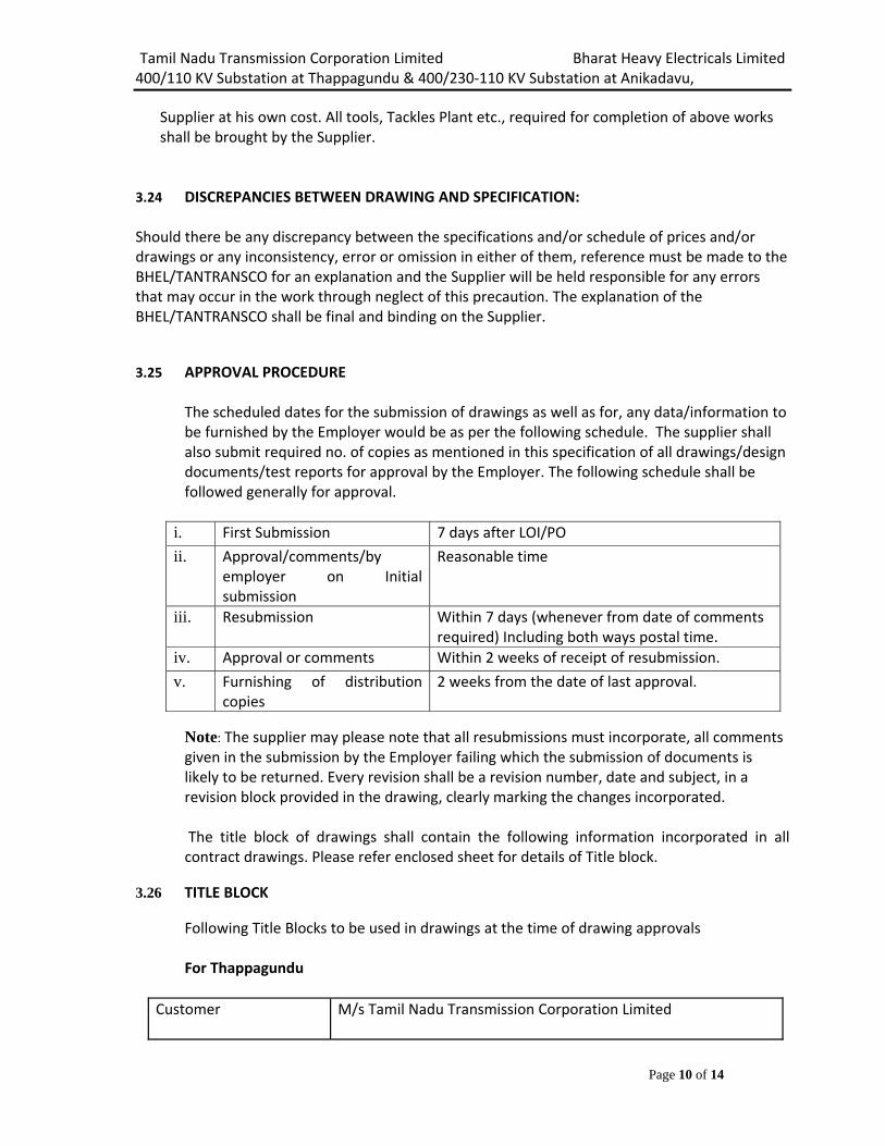
3.24 DISCREPANCIES BETWEEN DRAWING AND SPECIFICATION:
Should there be any discrepancy between the specifications and/or schedule of prices and/or drawings or any inconsistency, error or omission in either of them, reference must be made to the BHEL/TANTRANSCO for an explanation and the Supplier will be held responsible for any errors that may occur in the work through neglect of this precaution. The explanation of the BHEL/TANTRANSCO shall be final and binding on the Supplier. 3.25 APPROVAL PROCEDURE
The scheduled dates for the submission of drawings as well as for, any data/information to be furnished by the Employer would be as per the following schedule. The supplier shall also submit required no. of copies as mentioned in this specification of all drawings/design documents/test reports for approval by the Employer. The following schedule shall be followed generally for approval.
i. First Submission 7 days after LOI/PO
ii. Approval/comments/by employer on Initial submission
Reasonable time
iii. Resubmission Within 7 days (whenever from date of comments required) Including both ways postal time.
iv. Approval or comments Within 2 weeks of receipt of resubmission.
v. Furnishing of distribution copies
2 weeks from the date of last approval.
Note: The supplier may please note that all resubmissions must incorporate, all comments given in the submission by the Employer failing which the submission of documents is likely to be returned. Every revision shall be a revision number, date and subject, in a revision block provided in the drawing, clearly marking the changes incorporated.
The title block of drawings shall contain the following information incorporated in all contract drawings. Please refer enclosed sheet for details of Title block.
3.26 TITLE BLOCK Following Title Blocks to be used in drawings at the time of drawing approvals For Thappagundu
Customer M/s Tamil Nadu Transmission Corporation Limited
Tamil Nadu Transmission Corporation Limited Bharat Heavy Electricals Limited 400/110 KV Substation at Thappagundu & 400/230‐110 KV Substation at Anikadavu,
Page 11 of 14
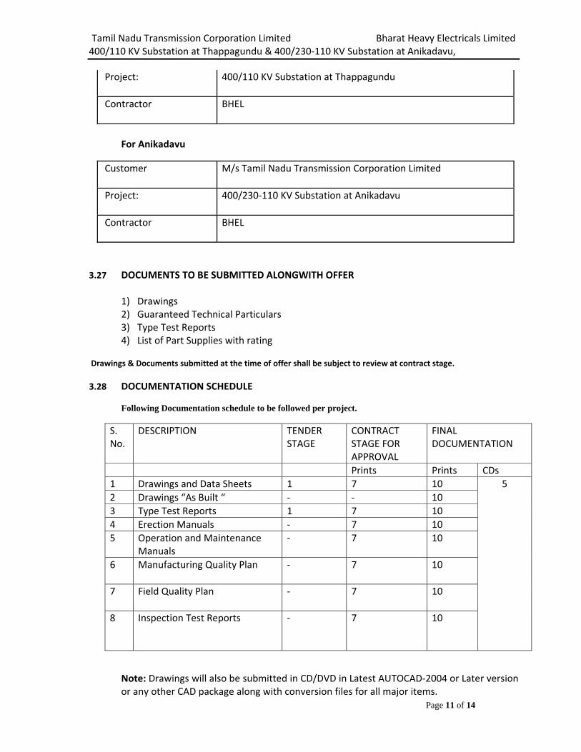
Project: 400/110 KV Substation at Thappagundu
Contractor BHEL
For Anikadavu
Customer M/s Tamil Nadu Transmission Corporation Limited
Project: 400/230‐110 KV Substation at Anikadavu
Contractor BHEL
3.27 DOCUMENTS TO BE SUBMITTED ALONGWITH OFFER
1) Drawings 2) Guaranteed Technical Particulars 3) Type Test Reports 4) List of Part Supplies with rating
Drawings & Documents submitted at the time of offer shall be subject to review at contract stage. 3.28 DOCUMENTATION SCHEDULE
Following Documentation schedule to be followed per project.
S. No.
DESCRIPTION TENDER STAGE
CONTRACT STAGE FOR APPROVAL
FINAL DOCUMENTATION
Prints Prints CDs 1 Drawings and Data Sheets 1 7 10 5
2 Drawings “As Built “ ‐ ‐ 10 3 Type Test Reports 1 7 10 4 Erection Manuals ‐ 7 10 5 Operation and Maintenance
Manuals ‐ 7 10
6 Manufacturing Quality Plan ‐ 7 10
7 Field Quality Plan ‐ 7 10
8 Inspection Test Reports ‐ 7 10
Note: Drawings will also be submitted in CD/DVD in Latest AUTOCAD‐2004 or Later version or any other CAD package along with conversion files for all major items.
Tamil Nadu Transmission Corporation Limited Bharat Heavy Electricals Limited 400/110 KV Substation at Thappagundu & 400/230‐110 KV Substation at Anikadavu,
Page 12 of 14
Final Documentation shall be submitted in bound volumes with details of Customer & Project etc. written on top.
Tamil Nadu Transmission Corporation Limited Bharat Heavy Electricals Limited 400/110 KV Substation at Thappagundu & 400/230‐110 KV Substation at Anikadavu,
Page 13 of 14
APPENDIX-A
SCHEDULE OF TECHNICAL DEVIATION
The following are the deviations/variations/exceptions from the specification:
In case, this schedule is not submitted, it will be presumed that the equipment /material to be supplied under this contract is deemed to be in compliance with the specification.
If there is NIL deviation, even then the format to be filled as NIL DEVIATION
Note: Continuation sheets of like size and format may be used as per the Bidder’s Requirement and shall be annexed to this schedule.
Place Signature of the authorized representative of
Date Bidder’s name …………………………………………….
Designation …………………………………………….
Company seal …………………………………………….
Tamil Nadu Transmission Corporation Limited Bharat Heavy Electricals Limited 400/110 KV Substation at Thappagundu & 400/230‐110 KV Substation at Anikadavu,
Page 14 of 14
APPENDIX-B
BIDDER’S UNDERTAKING FOR TYPE TEST REPORTS
Bidder shall take type test report, MQP, and drawing approval from TANTRANSCO without any commercial / delivery implication to BHEL. In case type test reports are not acceptable to customer due to any technical reason, the same shall be conducted free of cost.
Place Signature of the authorized representative of
Company seal -------------------------------------
Tamil Nadu Transmission Corporation Limited Bharat Heavy Electricals Limited 400/110 KV S/STN at Thappagundu & 400/230-110 KV S/STN at Anikadavu TB-363-510-012 Technical specification for WAVE TRAP Rev No. 00
1
SECTION-4
CHECK LIST FOR INFORMATION TO BE FURNISHED WITH OFFER
(RETURN THIS CHECKLIST AS PART OF THE OFFER DULY SIGNED) The offer may not be considered if the following information and this Checklist are not enclosed with the Offer.
BHEL ENQUIRY NO: BIDDER: OFFER REFERENCE: A) S. No. Parameters Data Yes /
NoRemarks
1. Applicable Standard IEC: 60353 with amendment, IS:8792,IS 8793, IEC: 60099 (Part I&IV), IS : 3072 (Part -I) and IS : 5561
2. Type 3.1 Rated Inductance
(Indentor to tick) 0.5 mH 1.0 mH
3.2 Rated Frequency 50 Hz
3.3 System Voltage (Indentor to tick)
765kV 400kV 230 kV 110 kV
3.4 Rated current (Indentor to tick)
3150 Amp. 2000 Amp.
1600 Amp.
1250 Amp. 800 Amp. 630 Amp.
3.5 Rated Short Circuit Current (Indentor to tick)
40 kA for 3 sec.
31.5 kA for 1 sec.
25 kA for 1Sec
3.6 Tuning device type (Indentor to tick)
Factory fixed Field adjustable
3.7 Type of tuning Broad Band
3.8 Tuning range (Indentor to tick from from frequency planning of PLCC)
50 to 90 kHz (for 1mH)
90 to 500 kHz (for 1mH)
90 to 150 kHz (for 0.5 mH)
150 to 500 kHz (for 0.5 mH)
3.9 Minimum blocking Impedance or resistance
Not less than 450 ohm (for 765 kV)
Not less than 450 ohm (for 400 kV)
Not less than 570 ohm (for 230 kV)
Not less than 570 ohm (for 132 kV)
3.10 Visual Corona Extinction voltage (Indentor to tick)
Not less than 508 kV (rms)
Not less than 320kV (rms) (for 400kV)
Not less than 156 kV (rms) (for
Not less than 105 kV (rms) (for
Tamil Nadu Transmission Corporation Limited Bharat Heavy Electricals Limited 400/110 KV S/STN at Thappagundu & 400/230-110 KV S/STN at Anikadavu TB-363-510-012 Technical specification for WAVE TRAP Rev No. 00
2
(for 765kV)
220 kV) 132 kV)
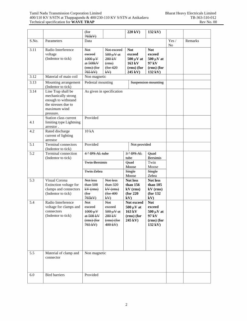
S.No. Parameters Data Yes / No
Remarks
3.11 Radio Interference voltage (Indentor to tick)
Not exceed 1000 μV at 508kV (rms) (for 765 kV)
Not exceed 500 μV at 280 kV (rms) (for 420 kV)
Not exceed 500 μV at 163 kV (rms) (for 245 kV)
Not exceed 500 μV at 97 kV (rms) (for 132 kV)
3.12 Material of main coil Non magnetic 3.13 Mounting arrangement
(Indentor to tick) Pedestal mounting Suspension mounting
3.14 Line Trap shall be mechanically strong enough to withstand the stresses due to maximum wind pressure.
As given in specification
4.1
Station class current limiting type Lightning arrestor .
Provided
4.2 Rated discharge current of lighting arrestor
10 kA
5.1 Terminal connectors (Indentor to tick)
Provided Not provided
5.2 Terminal connection (Indentor to tick)
4 " IPS Al. tube 3 " IPS Al. tube
Quad Bersimis
Twin Bersimis Quad Moose
Twin Moose
Twin Zebra Single Moose
Single Zebra
5.3 Visual Corona Extinction voltage for clamps and connectors (Indentor to tick)
Not less than 508 kV (rms) (for 765kV)
Not less than 320 kV (rms) (for 400 kV)
Not less than 156 kV (rms) (for 220 kV)
Not less than 105 kV (rms) (for 132 kV)
5.4 Radio Interference voltage for clamps and connectors (Indentor to tick)
Not exceed 1000 μV at 508 kV (rms) (for 765 kV)
Not exceed 500 μV at 280 kV (rms) (for 400 kV)
Not exceed 500 μV at 163 kV (rms) (for 245 kV)
Not exceed 500 μV at 97 kV (rms) (for 132 kV)
5.5 Material of clamp and connector
Non magnetic
6.0 Bird barriers Provided
Tamil Nadu Transmission Corporation Limited Bharat Heavy Electricals Limited 400/110 KV S/STN at Thappagundu & 400/230-110 KV S/STN at Anikadavu TB-363-510-012 Technical specification for WAVE TRAP Rev No. 00
3
B) TYPE TESTS i)Whether type test reports conducted earlier on identical or similar material are available(test reports are of the test conducted not earlier than 5 (five) years prior to the date of bid opening). (YES / NO) ii) If type test reports are not acceptable to BHEL/Customer then above tests shall be conducted by the bidder free of cost. (YES) Date: Signature of the authorized representative of Bidder