44
WaveLink PDH Digital Microwave Radio Communication System User Manual VER 1.0
WaveLink PDH
Digital Microwave Radio Communication
System
User Manual
VER 1.0

1
Table of Contents
Section 1 Product Introduction........................................................................ 4
1.1 General Description ................................................................................ 4
1.2 System Equipments ................................................................................ 4
1.3 System Features...................................................................................... 4
1.4 IDU Description ....................................................................................... 5
Section 2 Technical Specifications ................................................................. 7
2.1 Front Panel of IDU ................................................................................... 9
2.2 Frequency arrangement of an IF Cable ............................................... 11
Section 3 Supervision Controls ..................................................................... 12
3.1 Operation Procedure ............................................................................. 12
3.2 HyperTerminal settings ......................................................................... 12
3.3 Operating HyperTerminal...................................................................... 13
3.3.1 Parameter Setting. ....................................................................................13
3.3.2 HyperTerminal Tree Structure .................................................................14
3.3.3 Manual Operation ......................................................................................14
3.4 Manual commanding ............................................................................. 15
3.4.1 Item: Login system ....................................................................................15
3.4.2 Item: Main Menu ........................................................................................15
3.4.3 Item: Status ................................................................................................16
3.4.4 Item: System Test .....................................................................................18
3.4.5 Item: System Configuration ......................................................................21
3.4.6 Item: Remote Control ................................................................................23
3.4.7 Item: System Information .........................................................................24
3.4.8 Item: System Reset ...................................................................................24
3.4.9 Item: Exit ....................................................................................................24
3.4.10 Item: Chinese Edition..............................................................................24
3.5 Front Panel Display ............................................................................... 25
3.6 Keyboard on front panel ....................................................................... 25
Section 4 Field Installation ............................................................................. 30
4.1 IDU Installation ...................................................................................... 30
4.2 Electrifying Test ..................................................................................... 30
4.3 BER Test................................................................................................. 30
4.3.1 One Way BER Test: (Fading-less) ..........................................................30
4.3.2 Loopback Test: (Fading-less) ..................................................................31
Section 5 Maintenance and Troubleshooting ............................................... 32
5.1 Maintenance Check ............................................................................... 32
5.2 Troubleshooting .................................................................................... 32
5.3 Maintenance Notes ................................................................................ 32
Section 6 Packaging and Storage ................................................................. 34
6.1 Equipment ID ......................................................................................... 34

2
6.2 Packaging requirements ....................................................................... 34
6.3 Shipment and Storage Handlings ........................................................ 34
Appendix:Revision History .......................................................................... 35
Appendix:RF channel configuration for 5.8G ............................................ 36
Appendix:RF channel configuration for 13G ............................................. 37
Appendix:RF channel configuration for 15G ............................................. 40
Table of Figures
FIGURE 1 WAVELINK PDH SYSTEM EQUIPMENTS .......................................................... 4
FIGURE 2 IDU EQUIPMENT OUTLINE ............................................................................... 6
FIGURE 3 IDU FRONT PANEL OUTLINE ........................................................................... 9
FIGURE 4 FREQUENCY ARRANGEMENT OF AN IF CABLE ................................................ 11
FIGURE 5 RACK MOUNTING IDU .................................................................................... 30
FIGURE 6 ONE WAY BER TEST ..................................................................................... 31
FIGURE 7 LOOPBACK BER TEST.................................................................................... 31
FIGURE 8 TROUBLESHOOTING FLOW CHART ................................................................ 33

3
Welcome to read this User Guide
Thanks for using WaveLink PDH Digital Microwave Communication System. In
order for the reader to get familiar with equipment and gain more information on
operating guides, we highly recommend the reader to go through the outlined
sections of this guide step by step.
This guide would introduce the Indoor Unit (IDU), and the Outdoor Unit (ODU) and
the radio communication system.

4
Section 1 Product Introduction
1.1 General Description
WaveLink PDH digital microwave radio communication system is designed by
YTMW Technologies Ltd. The system is a high-performance, low-cost, secure and
reliable transmission products. The system includes Indoor unit (IDU), Outdoor
unit (ODU, the RF unit), antenna and all basic accessories. WaveLink PDH system
supply point-to-point radio connection in the telecommunications network, which is
widely used in enterprise access, interconnect base stations, emergency
communications, community access and relay connecting link.
The WaveLink PDH (IDU) is designed for different RF Unit working in different RF
frequency band, 7/8/13/15/18/23 GHz. And the IDU used the same IF interface to
connect to all these ODUs through coaxial cable.
1.2 System Equipments
Figure 1 WaveLink PDH System Equipments
1.3 System Features
Advanced technologies, Modular Design, high reliability and performance
Square-root Nyquist Roll-off Shaping, RS coding, QPSK modulation
Low power consumption
Rugged, compact, light weight IDU chassis, and all front wiring out
High system gain.
5
Easy and Quick Installation, only one coaxial cable to connect IDU and ODU,
automatic equalization (up to 300 m)
Various mounting methods for IDU, ODU and Antenna
Frequency Agility and Easy Tuning
Transmit Power Control, 1dB step, ATPC
System Flexibility, 2/4/8/16 E1 configurable capacity of IDU
System Flexibility, (1+0) unprotected or (1+1) Hot-Standby, using the same
IDU
IDU is used commonly for 7/8/13/15/18/23 GHz
Maintenance Facilities, Remote and local channel loop back (without external
equipment)
Local and remote supervision function on IDU
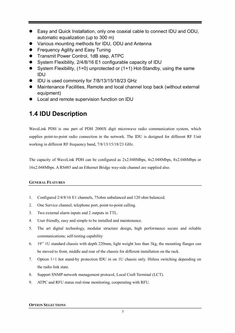
1.4 IDU Description
WaveLink PDH is one part of PDH 2000X digit microwave radio communication system, which
supplies point-to-point radio connection in the network. The IDU is designed for different RF Unit
working in different RF frequency band, 7/8/13/15/18/23 GHz.
The capacity of WaveLink PDH can be configured as 2x2.048Mbps, 4x2.048Mbps, 8x2.048Mbps or
16x2.048Mbps. A RS485 and an Ethernet Bridge way-side channel are supplied also.
GENERAL FEATURES
1. Configured 2/4/8/16 E1 channels, 75ohm unbalanced and 120 ohm balanced.
2. One Service channel, telephone port, point-to-point calling.
3. Two external alarm inputs and 2 outputs in TTL.
4. User friendly, easy and simple to be installed and maintenance.
5. The art digital technology, modular structure design, high performance secure and reliable
communications; self-testing capability
6. 19’’ 1U standard chassis with depth 220mm, light weight less than 3kg, the mounting flanges can
be moved to front, middle and rear of the chassis for different installation on the rack.
7. Option 1+1 hot stand-by protection IDU in on 1U chassis only. Hitless switching depending on
the radio link state.
8. Support SNMP network management protocol, Local Craft Terminal (LCT).
9. ATPC and RFU status real-time monitoring, cooperating with RFU.
OPTION SELECTIONS

6
ID Options Selections Description Order Info.
1 Capacity ○ 16xE1, configurable 2/4/8/16 E1
○ 8xE1, configurable 2/4/8 E1
○ 4xE1, configurable 2/4 E1
2 Configuration ○ 1+0 Configuration
○ 1+1 Hot Stand-by Protection
3 Supply Power ○ +/- (20 to 72) VDC
○ +/- (36 to 72) VDC
4 Ethernet
(Way-side)
○ None
○ 10BaseT
5 IF Interface ○ Transmit 310MHz / Receive 70MHz
EQUIPMENT OUTLINE (1+0)
Figure 2 IDU Equipment Outline

7
Section 2 Technical Specifications
WaveLink PDH IDU SPECIFICATIONS
GENERAL
LED Indicators 5 LEDs (3 state LEDs for Power, IDU, ODU;
Remote Alarm LED; Link state LED)
Line Interface Standards Compliance Compliant to ITU-T Rec. G.703, G.823
Line Code HDB3
Impedance 75 ohm unbalanced or 12 ohm balanced
IF Interface Transmit 310MHz, -7 to -2 dBm
Receive 70MHz, -30 to 0 dBm
IF Cable Connector N-Type
Protection Connector Optional 8 pin RJ45
Auxiliary Data Aux Data Channels 2
Interface 1 RS485 and Ethernet Bridge
Line Rate 1 9600bps for RS485, full-duplex, asynchronous
Interface 2 Ethernet Bridge, LAN port, RJ45
Line Rate 2 10BaseT, Over 200kbps, and
Configurable, 1 to 7 E1 data used for the port
Alarm I/O External Alarm Inputs 2 channels, TTL
External Alarm Outputs 2 channels, TTL, Drive Current >10mA
Connector 9 pin D-SUB
NMS LAN Interface Type 10BaseT Ethernet
Connector 8 pin RJ45
Maintenance Interface Standard RS232C, asynchronous
Baud rate 19200bps
Connector 9 pin D-SUB
Electrical Input Supply Power +/- (38 to 72) VDC, or +/- (20 to 72) VDC Optional
Connector ME050-50802, Taiwan DECA, 2 pins with flange
Power Consumption <15W
Protection Circuit 2A Fast-Blow Fuse
Mechanical Chassis Standard 19’’ 1U Chassis
Outline Dimension 482mm(W) x 246mm(D) x44mm (H)
Net Weight <3.5kg

8
CAPACITY OPTION 16E1
Capacity, configurable 16xE1, 8xE1, 4xE1, 2xE1
Traffic Connectors 2xDB44/Female
Accessory E1 Connection Wires 2 DB-to-BNC Connection Wires
CAPACITY OPTION 8E1
Capacity, configurable 8xE1, 4xE1, 2xE1
Traffic Connectors 2xDB44/Female
Accessory E1 Connection Wires 1 DB-to-BNC Connection Wires
PROTECTION OPTION
Protection Type 1+1 Hot Stand-by Protection
Switching < 5ms, hitless switching
WaveLink PDH ODU SPECIFICATIONS
SYSTEM
Radio Frequency
Band
Frequency
Range, GHz
T-R Spacing supported,
MHz
Maximum Tuning Range
(dependent upon T-R
spacing),MHz
7 GHz 7.125 to 7.9 154/161/245 56
8 GHz 7.725 to 8.5 119/126 140
13 GHz 12.75 to 13.25 266 84
15 GHz 14.4 to 15.35 315/420/490/644/728 245
18 GHz 17.7 to 19.7 1010/1092.5 380
23 GHz 21.2 to 23.632 1008/1200/1232 370
ANTENNA INTERFACE
Radio Frequency
Band
Waveguide Type Flange Type Mating Flange Type
7 GHz R84(WR112) UDR84 PDR84 OR CDR84
8 GHz R84(WR112) UDR84 PDR84 OR CDR84
13 GHz R120(WR75) UBR120 PBR120 OR CDR120
15 GHz R140(WR62) UBR140 PBR140 OR CBR140

9
18 GHz R220(WR42) UBR220 PBR220
23 GHz R220(WR42) UBR220 PBR220
WaveLink PDH SYSTEM PARAMETERS
Environment Operating Temperature -10℃~+50℃
Storage Temperature -40℃~+60℃
Humidity < 90%(non-condensing)
System Performance Receive C/N @BER10-6 ≥12dB
ATPC Range Configurable over full available ODU power range
Protection Switch Mode By Manual, or Automatically
Switch Conditions Refer to Receive C/N or Bit Error Rate Threshold
Switch Bit Error Non-hitless Switching
EMC Compliant with ITU-R F.746-3,YD1138-2001
System Configuration 1+0 non-protected or 1+1 Hot Stand-by protected
Modulation Modulation Type QPSK
FEC Concatenated Code: Reed-Solomon
Network Management SNMP Protocol supported
Maintenance and Monitor Service Telephone Telephone Port, Local-to-Remote Call
Local Maintenance LCT, LCD and keypad, Command line terminal
2.1 Front Panel of IDU
Figure 3 IDU Front Panel Outline
No. Features Descriptions
1 Ground
Connector Equipment grounding connector
2 ODU / IF IF interface, N-Type connector to be connected IDU to ODU

10
with IF coaxial-cable.
3
E1 TRIB 1-8
&
E1 TRIB 9-16
Traffic E1 interfaces:
E1 TRIB 1-8: DB44 connector for E1 ports from 1 to 8.
75ohm unbalanced.
E1 TRIB 9-16: DB44 connector for E1 ports from 6 to 16.
75ohm unbalanced.
For 2xE1 capacity: 1 to 2 ports are used and the other is
disabled.
For 4xE1 capacity: 1 to 4 ports are used and the other is
disabled.
For 8xE1 capacity: 1 to 8 ports are used and the other is
disabled.
For 16xE1 capacity: all ports are used.
The E1 signal cable would connect to these connectors.
4 ALARM I/O External alarms port, 2 inputs and 2 outputs.
5 COMPUTER
(RS232)
Supervision Interface, connect to the personal computer using
RS232 connecting wire.
6 ETHERNET ETHERNET: Ethernet bridge port for way-side data, RJ45.
7 NMS Network management Ethernet port, RJ45
8 PROTECTION Protection port. RS485 electric voltage
9 DATA (RS485) DATA (RS485): Asynchronous data port, RJ45, RS485
electric voltage
10 LED Lights
5 LEDs have two states: brighten and darken. PWR:Green light to indicate power on
IDU:Red light to indicate IDU error, no light means normal
ODU:Red light to indicate ODU error, no light means normal
AIS:Red light to indicate remote station error, no light means
normal
LNK:Green light to indicate system traffic link is connected
well, no light means the link is interrupted and failed to
connect to remote station.
11 ESC Button to go backward or exit
12 UP Button to go upward or plus 1 to number in setting
13 DOWN Button to go downward or minus 1 to number in setting
14 ENTER Button to issue command or go into the sub menu.
15 LCD LCD Screen
16 FUSE Fuse for the supply power input.
17 EOW Port connected to a regular phone set
18 Power Socket Connected to supply power.

11
The ground end of supply power MUST be
connected to the “GND” end of the socket.
19 PWR Power switch
2.2 Frequency arrangement of an IF Cable
Figure 4 Frequency arrangement of an IF Cable

12
Section 3 Supervision Controls
3.1 Operation Procedure
WaveLink PDH can be operated in three forms
1) LCD panel;
2) HyperTerminal;
3) NMS port.
IDU without front LCD display should be system controlled by HyperTerminal
Controls can be monitored via the LCD panel or the HyperTerminal
3.2 HyperTerminal settings
User can use HyperTerminal on Windows to manage the equipment through
supervision interfaces. The main content of control management includes: Login
management, Data link testing, system alert, power and environmental status,
equipment status, alert management, equipment maintenance and parameter
settings.
Parameters of supervision interface:
Supervision interface adopts RS-232 to interface: Full duplex, Baud rate=19200
b/s; Stop bits=1.5 or 2; Data bits=8; Parity=None; Flow control=None.
Main functions
Login authorization management
To stop illegal accessing the management system, the password management
was used in the system. User can change the password. Special attention: User
should log-off the system after operating to avoid illegal user from accessing.
(Default: No Password, press ENTER key to login).
Voltage status
Users can monitor the internal operating voltage. The equipment will show relative
alert when the voltage of some group out of Spec.
Data-link test and Status warning
Users can test and review the Branch Link and Multiplex Link of each E1, it
includes Mux-link loopback test, interrupt check and AIS warning; Mux-link BER
test、automatic link switch and system delay re-start.
Equipment status and Alarm management
Users can check the equipment status and alarm while operating, and define the

13
notify way and alarm level.
Equipment Maintenance and parameter setting
Users can save the parameters to prevent parameter losing after power off. Users
can set the parameter quite easily, such as to open/close the branch link; back up
selection of multiplex link; set/change password and equipment name; save/reload
equipment parameters
Equipment Maintenance includes: hardware module troubleshooting and link
testing. Do Troubleshooting to find out the root causes of hardware mal-functions
quickly.
Remote control
Users can control the remote equipment through the local equipment.
3.3 Operating HyperTerminal
3.3.1 Parameter Setting.
HyperTerminal operating steps:
Step 1:
Run “Start\All programs\Accessories\Communications\HyperTerminal” in Windows
OS.
Step 2:
Select one port and set the parameter for communication:
Baud rate=19200 b/s; Stop bits=1; Data bits=8; Parity=None; Flow control=None.

14
3.3.2 HyperTerminal Tree Structure
━【Login System】
━【Main Menu】
━【Status】
┃ ━【Link Status】
┃ ━【Power Status】
┃ ━【RF Unit Status】
━【Test】
┃ ━【Link Loop Test】
┃ ━【Link Status】
┃ ━【Cancel All Loopback】
┃ ━【Local Loop Test】
┃ ━【Remote Loop Test】
┃ ━【Hardware Test】
┃ ━【RF PA Mute】
━【Configuration】
┃ ━【RF Unit】
┃ ━【General Settings】
┃ ━【E1 Function】
┃ ━【E1/Ethernet Ports】
┃ ━【Auto Alarm Function】
┃ ━【Auto LCM Screen Protect】
┃ ━【Change Equipment ID Address】
┃ ━【Ethernet Port】
┃ ━【Change Password】
┃ ━【Change Station Name】
┃ ━【Load Factory Settings】
┃ ━【Load Last Settings】
┃ ━【Save Current Settings】
━【Remote Access】
┃ ━【Back to Main Menu
┃ ━【Access Remote Equipment】
┃ ━【Software Reset Timer】
┃ ━【Call Remote Equipment】
━【Info】
━【Reset】
━【Exit】
━【Chinese 中文】
3.3.3 Manual Operation
User can use HyperTerminal system to command supervision software. The

15
common method is to input alphabetical letters or integers such as 1, 2, and 3
etc…, then press then enter key to dispatch orders. User can also use <ESC> key
to go back to previous page or cancel present inputs. “0” command go back to
previous order.
3.4 Manual commanding
3.4.1 Item: Login system
Login the HyperTerminal system, the page will show:
It’s necessary to follow the login procedure to enter the HyperTerminal system.
Users need passwords to log into the supervision system. System allows 3 times,
log-in. If invalid, users need to re-start the system.
3.4.2 Item: Main Menu
The display window of Main Menu shows:
+---------+ WaveLink PDH Digital Microwave Communication System +---------+
<Login System>
Welcome To Visit Our
WaveLink PDH Digital Microwave Communication System
Press <0> Key To Login System

16
Main Menu comprises ENTRANCE/EXIT/RESTART functions to interface with all
system management. It’s necessary to login for restart supervising tasks.
Description of Commands:
1. Status // System status and warning management
2. Test // Proceed link and hardware functional testing
3. Configuration // Set up system parameters
4. Remote access // Control and de-control far end equipment
5. Info // System messages
6. Reset // Software to restart the system
7. Exit // Exit the text menu
8. 中文(Chinese) // Enter Chinese version.
3.4.3 Item: Status
System Status screen is shown below:
+---------+ WaveLink PDH Digital Microwave Communication System +---------+
<Main Menu>
@ 1. Status
2. Test
3. Configuration
4. Remote Access
5. Info
6. Reset
7. Exit
8. 中文(Chinese)

17
The status showing in current screen is NOT a real-time message; you
should refresh the message by pressing the “Space” key
1 Link Status // Check the Link Status
2 Power Status // Check the Power Status
Choose Link Status, the screen will show:
Choose Power Status, the screen will show:
+---------+ WaveLink PDH Digital Microwave Communication System +---------+
<Link Status>
*. E1#1 Port Status: LOS
*. E1#2 Port Status: LOS
*. E1#3 Port Status: LOS
*. E1#4 Port Status: LOS
*. Service RF Link: Master
*. Mux Link Status: SYN
*. Modem Status:
. Demodulator: s84 a80 eFFF0 n23
. Tx IF LO: Locked
. Rx IF LO: Locked
+---------+ WaveLink PDH Digital Microwave Communication System +---------+
<System Status>
@ 1. Link Status
2. Power Status
3. RF Unit Status
>>Enter Command: 1

18
This function is to display the voltage for each group.
3.4.4 Item: System Test
System Test pages shows:
1. Link Loop Test // Local and remote loop back over the data links.
2. Hardware Test // States of some hardware unit
3. RFPA Mute // on or off the FR PA
+---------+ WaveLink PDH Digital Microwave Communication System +---------+
<System Test>
@ 1. Link Loop Test
2. Hardware Test
3. RF PA Mute: OFF(RF Power Output Normally)
>>Enter Command: 1
+---------+ WaveLink PDH Digital Microwave Communication System +---------+
<Power Status>
@ 1. Power (+5V ±5%): 5.11V
2. Power (+12V ±5%): 13.83V
>>Enter Command: 1

19
Link test screen shows:
The function is to test multiplex links and sub-links, local and remote included.
For normal operation, make sure to close all loop functions after all
tests were done. All loops should be closed when restart or re-load
the system.
1. Link Status: //Enter 【Link Status Loop Test】menu
2. Cancel All Loop
3. Local Loop test //Enter 【Local Loop test】menu
4. Remote Loop test //Enter 【Remote Loop test】menu
Local loop screen shows:
+---------+ WaveLink PDH Digital Microwave Communication System +---------+
<Link Test>
@ 1. Link Status
2. Cancel All Loopback
3. Local Loop Test
4. Remote Loop Test
>>Enter Command: 1

20
Remote loop screen is shown below:
“Looped” means the pointed link is in looping stage. “Blank space” means the link
is in normal condition. Use “enter” key to switch checking the looping status.
Hardware Test screen is shown below:
+---------+ WaveLink PDH Digital Microwave Communication System +---------+
<Remote Loop>
@ 1. E1#1 Remote Loop: Looped
2. E1#2 Remote Loop:
3. E1#3 Remote Loop:
4. E1#4 Remote Loop:
>>Enter Command: 1
+---------+ WaveLink PDH Digital Microwave Communication System +---------+
<Local Loop>
1. E1#1 Local Loop: Looped
2. E1#2 Local Loop:
3. E1#3 Local Loop:
4. E1#4 Local Loop:
@ A. Mux Link Local Loop: Looped
>>Enter Command: A

21
This function is to check EEPROM, IC1/IC2/IC3, LIU Circuits, ADC Circuits, Tel
Circuits and Modem automatically. After command entered, the system will check
the hardware module. The test result will be indicated in “Normal” or “Error”
conditions.
3.4.5 Item: System Configuration
The System Configuration page looks like:
After the parameter is changed, it won’t save the setting automatically, need to
perform the command “Save Current Settings” before parameters saving.
+---------+ WaveLink PDH Digital Microwave Communication System +---------+
<System Configuration>
@ 1. RF Unit
2. General Settings
3. Ethernet Port
4. Change Password: <NONE>
5. Change Station Name: Unnamed
6. Load Factory Settings
7. Load Last Settings
8. Save Current Settings
Hardware Test:
EEPROM............Normal
IC1/IC2...........Normal
LIU Circuits 1)...Normal
LIU Circuits 2)...Normal
ADC Circuits......Normal
Tel Circuits......Normal
Modem.............Normal
IC6...............Normal
Test Done, Any Key to Continue...

22
“Password Change”: Select “4” and press “Enter”, “Please type password”
will be showed. The digit number of password is 1 to 8.
Station Name: To identify machine ID, Maximum digits of Chinese character is 8.
The page for General Settings looks like:
E1 Function page is shown below as:
You can change setting to “Enabled” or “Disabled” by pressing “Enter”
+---------+ WaveLink PDH Digital Microwave Communication System +---------+
<E1 Function>
1. E1 Port#1 Function: Enabled
@ 2. E1 Port#2 Function: Disabled
3. E1 Port#3 Function: Enabled
4. E1 Port#4 Function: Enabled
>>Enter Command: 2
+---------+ WaveLink PDH Digital Microwave Communication System +---------+
<General Settings>
@ 1. Baseband Function
2. Change IP
3. Auto Alarm Function: On
4. Auto LCM Screen Protect: On
5. Change Equipment ID Address: 000
6. External Alarm Output 1:Undefined (Output: LOW)
7. External Alarm Output 2:Undefined (Output: LOW)
>>Enter Command: 1

23
1. E1 Port Number: How many E1 channel is(are) for Ethernet
2. Ethernet Port: Disabled/Enable
The setting for Ethernet Port:
This function is to set which E1 channel is (are) for Ethernet
3.4.6 Item: Remote Control
Remote Control page is shown below:
+---------+ WaveLink PDH Digital Microwave Communication System +---------+
<Ethernet Port>
Z. Ethernet Mode: 3
>> Select E1 Channels For Ethernet Port:
@ 1. Channel E1#1: E1 Service Data
2. Channel E1#2: E1 Service Data
3. Channel E1#3: E1 Service Data
4. Channel E1#4: E1 Service Data
>>Enter Command: 1
+---------+ WaveLink PDH Digital Microwave Communication System +---------+
<Remote Access>
Operating On: Local Equipment! Station Name:
@ 1. Back To Main Menu
2. Access Remote Equipment
3. Software Reset Timer: Stopped
4. Call Remote Equipment
>>Enter Command: 1

24
The system can control the remote equipment by performing the local control. If
the communication link is normal, users can access remote interface by getting
into the “Remote Access” menu. Users can also get out of the remote access
interface by hitting “Cancel” command. If the communication link is interrupted
and system shows no response, users need to activate the HyperTerminal menu.
3.4.7 Item: System Information
3.4.8 Item: System Reset
After the reset command is performed, the system parameter will be reloaded and
system will be re-started.
If system runs in normal condition please do not perform this
command.
3.4.9 Item: Exit
This command is for quitting the HyperTerminal program.
3.4.10 Item: Chinese Edition
The page of Chinese Edit looks like:
Use the English menu format to design the Chinese menu.

25
3.5 Front Panel Display
Definitions to the Keyboard on front panel
“Esc” (return or exit): Returning to up level menu or exit to stand-by interface ”▲” (Up or plus 1):
Move up menu in operation status or add one in setting status;
”▼” (Down or minus 1):
Move down in operation status or minus one in setting status;
”Enter” (confirm):
(1)Enter main menu from standby interface;
(2)Choose sub-menu to enter ;
(3)Save the setting;
3.6 Keyboard on front panel
LCD displays messages and commands intuitively and user friendly to operate.
Main menu is shown on right Displaying the brand name and
logo. Press < > to enter the Main Menu.
The Main Menu is shown on right
1. Status// System and alarm states
2. Test //Link and Hardware tests
3. Configuration // system settings
4. Remote Access// Far-end control
5. Information // General displaying
6. Chinese 中文// Access the Chinese interface
The Status menu is shown on right
1. Link and E1 ports // Check E1 link status
2. Modem// Check Modem
3. RF Unit Info // Check RF Unit Info
【Main Menu】
1. Status
2. Test
3. Configuration
4. Remote Access
5. Information
6. Chinese 中文
PDH
WaveLink
【System Status】
1. Link and E1 ports
2. Modem
3. RF Unit Info
4. Powers

26
4. Powers // Check Power
Link status display
1. interrupt:No signal
2. losing:Serious error code rate
3. all ”1”: all ”1” received within a frame cycle
4. normal:Link is going in normal。
Modem display
1. “s”: Status 2. “a”: AGC 3. “e”: Error code 4. “n” Signal to noise ratio 5. The number behind “s”, “a” ,“e”, “n”
is Hexadecimal.
RF Unit display
1. StationType: 2. Tx Power:
Power display
1. Display voltage readings
System Test display
【Powers】
+5V DC: 5.06V
+12V DC: 12.53V
【Link Status】
* E1#1: Normal/interrupt
* E1#2: Normal/ interrupt
* E1#3: Normal/ interrupt
* E1#4: Normal/ interrupt
* Mux Link: OK
【SystemTest】
1 Link Loop 2 Baseband L_ Loop 3 Baseband R_ Loop
4 Cancel Test 5 Hardware Test
6 RF PA Mute:
7 Reset System!!!!
【RF Info】
1 Channel: xx
2 StationType: Low/High
3. Tx Power (dBm): xx
【Modem Status】
1. Modem Status
s9B a0A e0003 n19
2. Tx IF LO: Locked/Error
3. Rx IF LO: Locked/Error

27
Hardware Test…
Circuits are OK!
Setup OK:
: No RF Power Output! //RF
Output Normally
Cancel ?.... 4s
1. Link Loop //Enter【Link Loops】menu
2. Baseband L_Loop //Baseband Local Loop
3. Baseband R_Loop //Baseband Remote Loop
4. Cancel Test
5. Hardware Test //Equipment hardware test
6. RF PA Mute // “On” or “off” the RF PA
7. Reset System. //Reset the system Link Loop display
1. “On” - Link is in loop mode
2. Blank space - Link is in normal mode Baseband L_ Loop display
1. “On” - Link is in loop mode 2. Blank space - Link is in normal mode 3. L Cancel E1 Loops // Cancel local loop settings
Baseband R_ Loop display
1. “On” - link is in loop mode 2. Blank space - Link is in normal mode 3. R Cancel E1 Loops //Cancel remote loop settings
Hardware Test display
The name of problem hardware would be given. If the hardware is found for something fault; otherwise, showing normal means circuits are working well. RF PA Mute page is shown on right 1. “On” means No RF Power Output 2. Blank space means RF Output Normally
【Link Loop】
1 Local loop: On/ * Hardware Loop
【E1 L_Loops】
L E1#01 L_Loop: On/
L E1#02 L_Loop: On/ L E1#03 L_Loop: On/ L E1#04 L_Loop: On/ … L Cancel E1 Loops
【E1 R_Loops】
R E1#01 R_Loop: On/
R E1#02 R_Loop: On/ R E1#03 R_Loop: On/ R E1#04 R_Loop: On/ … R Cancel E1 Loops

28
Reset System page is shown on right
The system will be reset within 4 seconds, and press the key “Enter” to cancel the command.
Configuration page is shown on right 1. RF Unit; 2. General Setting // 3. Ethernet // 4. E1 Ports// 5. Load factory // Load default setting; 6. Load Last // Load the setting of last time; 7. Save Setting // Save the settings.
General display
1. “On” means E1 is on open status
2. “Off” means E1 is on close status
Ethernet display
1. Ethernet : None
(“None” is displayed if no Ethernet Module)
2. Press the key ”Enter” to change setting
to E1 Data or Ethernet Data
RF unit display
1. Channel: Change the channel number
2. Tx Power: Change Tx Power
3. Apply New RF: Apply a new RF.
【General】
1 Auto Alarm: On/Off
2 Screen Protect: On/Off
3 Menu Loop: On/Off
【RF Unit】
1 Channel: xx
2 Tx Power(dBm): xx
3 Apply New RF
4 Rx Unit Info
5 Freq. Cfg
【Configurations】
1 RF Unit
2 General Settings
3 Ethernet
4 E1 Ports
5 Load Factory
6 Load Last
7 Save Settings
【Ethernet】
E1#1: E1 Data/Ethernet Data
E1#1: E1 Data/Ethernet Data
E1#1: E1 Data/Ethernet Data
E1#1: E1 Data/Ethernet Data
...

29
E1 Ports display
Enabled: Function is avaiable Closed: Function is closed Press the ”Enter” key to change the setting to “Enable ” Or to “Closed” status.
Load Factory display
Press “Enter” key to load default settings
Load Last display
Press “Enter” key to load the settings of Last time
Save Settings display
After setting finished, press “Enter” key to save The monitor screen will show “Completed”
Remote display
1. press “Enter” to get in 2. “Reset Timer” to count down 3. Call Remote // key “Enter” to get in
System Info display
1. Show company related information 2. Show equipment related information
【System Info】
Model: WaveLink
…
Please waiting
Done!
【Remote】
* CurrentEquipment:Local
1 Access Remote
2 Reset Timer:
Counting Down : 10 /Stopped
3 Call Remote
【BB Function】
1 E1#01 Fun: Enabled/Closed
2 E1#02 Fun: Enabled/Closed
3 E1#03 Fun: Enabled/Closed
4 E1#04 Fun: Enabled/Closed
…
Done!
Please Wait…
Done!

30
Section 4 Field Installation
4.1 IDU Installation
The indoor unit (IDU) shall be installed on a standard rack inside the link stations.
The power and grounding wires should be well connected to meet their individual
design specs. Make sure the power to be supplied is safely rated for the IDU.
Figure 5 Rack mounting IDU
4.2 Electrifying Test
After adjusting the antennas, the link devices in corresponding stations can be
energized for running. If system runs in normal conditions, there will be no warning
indicators flashing.
4.3 BER Test
4.3.1 One Way BER Test: (Fading-less)
A station to transmit and B station to receive – No BER error occurs.
B station to transmit and A station to receive – No BER error occurs.

31
N*E
1In
terf
ace
IF M
OD
EM
Mu
ltip
lex
er /
D
emu
ltip
ler
tran
scei
ver
N*E
1In
terf
ace
Mu
ltip
lex
er /
D
emu
ltip
ler
IF M
OD
EM
tran
scei
ver
Figure 6 One Way BER Test
4.3.2 Loopback Test: (Fading-less)
Loop start from station A and conduct BER test at loop end of station B. No BER
error occurs. Or route the other way around (loop from station B to station A).
Figure 7 Loopback BER Test

32
Section 5 Maintenance and Troubleshooting
5.1 Maintenance Check
Check on Power;
Check cable connections;
Check battery power (should be within –48v ±20%);
Check light indicators;
Check weather conditions (temperature, humidity, etc.)
Conduct Maintenance check at least once a month.
5.2 Troubleshooting
If something wrong with the equipment, please do not dismantle it without getting authorization from supplier. Always check thoroughly by following the recommended steps: Use monitoring software or user guide to check (Failure analysis flow chart)
Same way to check the other link
Check failure symptoms at both links
Find out root causes at both links
If user wants to fix the failure, please consult experienced technical staff for getting
step by step problem-solving suggestions.
5.3 Maintenance Notes
Maintenance process should be done by or under the guidance of authorized
Professional engineers.
Re-start the equipment (after power-off) and wait for 30 seconds, the
equipment should operate back to normal.
During maintenance session, parameters could be changed or revised. Be
sure to change back to initial status after the completion of maintenance
session.
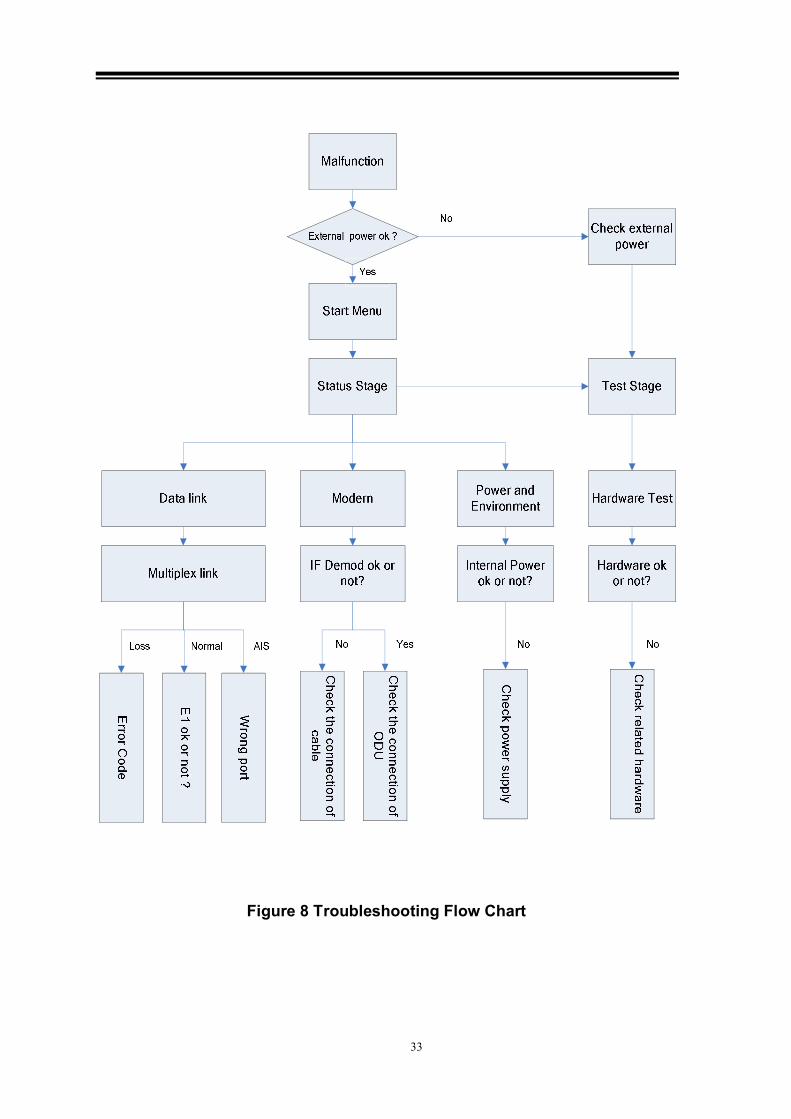
33
Figure 8 Troubleshooting Flow Chart

34
Section 6 Packaging and Storage
6.1 Equipment ID
Product Name, Model No., Serial No. must be clearly marked in a designated area
on the Product.
6.2 Packaging requirements
Packaging Check list
User Guide
Inspection Certificate
6.3 Shipment and Storage Handlings
Follow packaging specs to choose the packaging material and packaging
procedure to pack the finish product accordingly.
User Guide, Inspection Certificate and Packing List should be included in box.
Product would be delivered via airway, land and sea expressways by avoiding any
hazardous situations such as: rain, flood, storm, snow or any possible natural
impacts.
Require good ventilation system in the storage room. Keep storage temperature in
a range of -10~+40 and control humidi℃ ty to be lowered than 85% and keep the
products away from any hazardous chemical compounds or toxic gas.

35
Appendix:Revision History
Revision Changes Date
VER 1.0 Original 2008-06-20
Rev1 WaveLink PDH System User Manual
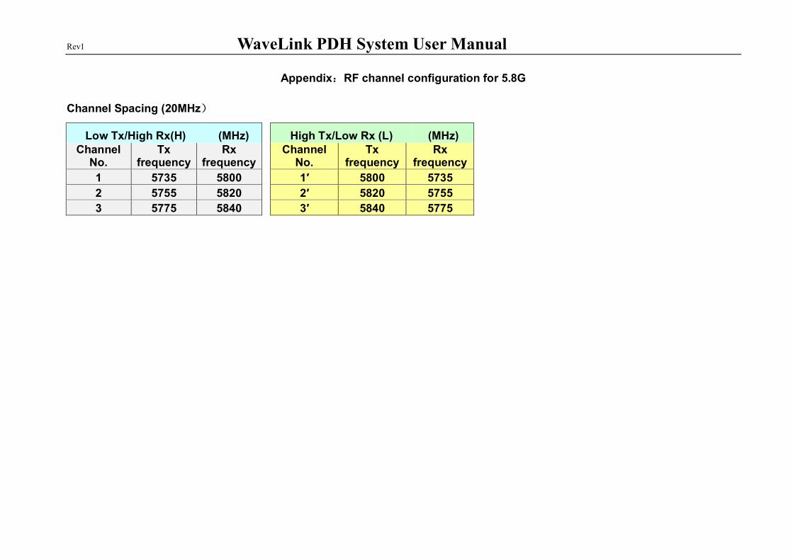
Appendix:RF channel configuration for 5.8G
Channel Spacing (20MHz)
Low Tx/High Rx(H) (MHz) High Tx/Low Rx (L) (MHz) Channel
No. Tx
frequency Rx
frequency Channel
No. Tx
frequency Rx
frequency
1 5735 5800 1′ 5800 5735
2 5755 5820 2′ 5820 5755
3 5775 5840 3′ 5840 5775

Rev1 WaveLink PDH System User Manual
Appendix:RF channel configuration for 13G
13GHZ
Frequency Range 12750 to 13250MHZ
Number of channels 32 pairs
Separation of channels 7 MHZ
T-R Spacing 266 MHZ
Capacity 34.368;51.840;139.264;155.52 Mbits/s
Channel Centeer Low High Channel Centeer Low High
1 12754.50 12751.00 12758.50 1' 13020.50 13017.00 13024.00
2 12761.50 12758.00 12765.50 2' 13027.50 13024.00 13031.00
3 12768.50 12765.00 12772.50 3' 13034.50 13031.00 13038.00
4 12775.50 12772.00 12779.50 4' 13041.50 13038.00 13045.00
5 12782.50 12779.00 12786.50 5' 13048.50 13045.00 13052.00
6 12789.50 12786.00 12793.50 6' 13055.50 13052.00 13059.00
7 12796.50 12793.00 12800.50 7' 13062.50 13059.00 13066.00
8 12803.50 12800.00 12807.50 8' 13069.50 13066.00 13073.00
9 12810.50 12807.00 12814.50 9' 13076.50 13073.00 13080.00
10 12817.50 12814.00 12821.50 10' 13083.50 13080.00 13087.00
11 12824.50 12821.00 12828.50 11' 13090.50 13087.00 13094.00
12 12831.50 12828.00 12835.50 12' 13097.50 13094.00 13101.00
13 12838.50 12835.00 12842.50 13' 13104.50 13101.00 13108.00
14 12845.50 12842.00 12849.50 14' 13111.50 13108.00 13115.00
15 12852.50 12849.00 12856.50 15' 13118.50 13115.00 13122.00
16 12859.50 12856.00 12863.50 16' 13125.50 13122.00 13129.00

Rev1 WaveLink PDH System User Manual
17 12866.50 12863.00 12870.50 17' 13132.50 13129.00 13136.00
18 12873.50 12870.00 12877.50 18' 13139.50 13136.00 13143.00
19 12880.50 12877.00 12884.50 19' 13146.50 13143.00 13150.00
20 12887.50 12884.00 12891.50 20' 13153.50 13150.00 13157.00
21 12894.50 12891.00 12898.50 21' 13160.50 13157.00 13164.00
22 12901.50 12898.00 12905.50 22' 13167.50 13164.00 13171.00
23 12908.50 12905.00 12912.50 23' 13174.50 13171.00 13178.00
24 12915.50 12912.00 12919.50 24' 13181.50 13178.00 13185.00
25 12922.50 12919.00 12926.50 25' 13188.50 13185.00 13192.00
26 12929.50 12926.00 12933.50 26' 13195.50 13192.00 13199.00
27 12936.50 12933.00 12940.50 27' 13202.50 13199.00 13206.00
28 12943.50 12940.00 12947.50 28' 13209.50 13206.00 13213.00
29 12950.50 12947.00 12954.50 29' 13216.50 13213.00 13220.00
30 12957.50 12954.00 12961.50 30' 13223.50 13220.00 13227.00
31 12964.50 12961.00 12968.50 31' 13230.50 13227.00 13234.00
32 12971.50 12968.00 12975.50 32' 13237.50 13234.00 13241.00
13GHZ
Frequency Range 12750 to 13250MHZ
Number of channels 8 pairs
Separation of channels 28 MHZ
T-R Spacing 266 MHZ
Capacity 34.368;51.840;139.264;155.52 Mbits/s
Channel Centeer Low High Channel Centeer Low High
1 12765.00 12751.00 12779.00 1' 13031.00 13017.00 13045.00
2 12793.00 12779.00 12807.00 2' 13059.00 13045.00 13073.00
3 12821.00 12807.00 12835.00 3' 13087.00 13073.00 13101.00
4 12849.00 12835.00 12863.00 4' 13115.00 13101.00 13129.00

Rev1 WaveLink PDH System User Manual
5 12877.00 12863.00 12891.00 5' 13143.00 13129.00 13157.00
6 12905.00 12891.00 12919.00 6' 13171.00 13157.00 13185.00
7 12933.00 12919.00 12947.00 7' 13199.00 13185.00 13213.00
8 12961.00 12947.00 12975.00 8' 13227.00 13213.00 13241.00

Rev1 WaveLink PDH System User Manual
Appendix:RF channel configuration for 15G
15GHZ
Frequency Range 14500 to 15350MHZ
Number of channels 60 pairs
Separation of channels 7 MHZ
T-R Spacing 420 MHZ
Capacity 2.048;2x2.048;8.448 Mbits/s
Channel Centeer Low High Channel Centeer Low High
1 14504.50 14501.00 14508.00 1' 14924.50 14921.00 14928.00
2 14511.50 14508.00 14515.00 2' 14931.50 14928.00 14935.00
3 14518.50 14515.00 14522.00 3' 14938.50 14935.00 14942.00
4 14525.50 14522.00 14529.00 4' 14945.50 14942.00 14949.00
5 14532.50 14529.00 14536.00 5' 14952.50 14949.00 14956.00
6 14539.50 14536.00 14543.00 6' 14959.50 14956.00 14963.00
7 14546.50 14543.00 14550.00 7' 14966.50 14963.00 14970.00
8 14553.50 14550.00 14557.00 8' 14973.50 14970.00 14977.00
9 14560.50 14557.00 14564.00 9' 14980.50 14977.00 14984.00
10 14567.50 14564.00 14571.00 10' 14987.50 14984.00 14991.00
11 14574.50 14571.00 14578.00 11' 14994.50 14991.00 14998.00
12 14581.50 14578.00 14585.00 12' 15001.50 14998.00 15005.00
13 14588.50 14585.00 14592.00 13' 15008.50 15005.00 15012.00
14 14595.50 14592.00 14599.00 14' 15015.50 15012.00 15019.00
15 14602.50 14599.00 14606.00 15' 15022.50 15019.00 15026.00

Rev1 WaveLink PDH System User Manual
16 14609.50 14606.00 14613.00 16' 15029.50 15026.00 15033.00
17 14616.50 14613.00 14620.00 17' 15036.50 15033.00 15040.00
18 14623.50 14620.00 14627.00 18' 15043.50 15040.00 15047.00
19 14630.50 14627.00 14634.00 19' 15050.50 15047.00 15054.00
20 14637.50 14634.00 14641.00 20' 15057.50 15054.00 15061.00
21 14644.50 14641.00 14648.00 21' 15064.50 15061.00 15068.00
22 14651.50 14648.00 14655.00 22' 15071.50 15068.00 15075.00
23 14658.50 14655.00 14662.00 23' 15078.50 15075.00 15082.00
24 14665.50 14662.00 14669.00 24' 15085.50 15082.00 15089.00
25 14672.50 14669.00 14676.00 25' 15092.50 15089.00 15096.00
26 14679.50 14676.00 14683.00 26' 15099.50 15096.00 15103.00
27 14686.50 14683.00 14690.00 27' 15106.50 15103.00 15110.00
28 14693.50 14690.00 14697.00 28' 15113.50 15110.00 15117.00
29 14700.50 14697.00 14704.00 29' 15120.50 15117.00 15124.00
30 14707.50 14704.00 14711.00 30' 15127.50 15124.00 15131.00
31 14714.50 14711.00 14718.00 31' 15134.50 15131.00 15138.00
32 14721.50 14718.00 14725.00 32' 15141.50 15138.00 15145.00
33 14728.50 14725.00 14732.00 33' 15148.50 15145.00 15152.00
34 14735.50 14732.00 14739.00 34' 15155.50 15152.00 15159.00
35 14742.50 14739.00 14746.00 35' 15162.50 15159.00 15166.00
36 14749.50 14746.00 14753.00 36' 15169.50 15166.00 15173.00
37 14756.50 14753.00 14760.00 37' 15176.50 15173.00 15180.00
38 14763.50 14760.00 14767.00 38' 15183.50 15180.00 15187.00
39 14770.50 14767.00 14774.00 39' 15190.50 15187.00 15194.00
40 14777.50 14774.00 14781.00 40' 15197.50 15194.00 15201.00
41 14784.50 14781.00 14788.00 41' 15204.50 15201.00 15208.00
42 14791.50 14788.00 14795.00 42' 15211.50 15208.00 15215.00
43 14798.50 14795.00 14802.00 43' 15218.50 15215.00 15222.00

Rev1 WaveLink PDH System User Manual
44 14805.50 14802.00 14809.00 44' 15225.50 15222.00 15229.00
45 14812.50 14809.00 14816.00 45' 15232.50 15229.00 15236.00
46 14819.50 14816.00 14823.00 46' 15239.50 15236.00 15243.00
47 14826.50 14823.00 14830.00 47' 15246.50 15243.00 15250.00
48 14833.50 14830.00 14837.00 48' 15253.50 15250.00 15257.00
49 14840.50 14837.00 14844.00 49' 15260.50 15257.00 15264.00
50 14847.50 14844.00 14851.00 50' 15267.50 15264.00 15271.00
51 14854.50 14851.00 14858.00 51' 15274.50 15271.00 15278.00
52 14861.50 14858.00 14865.00 52' 15281.50 15278.00 15285.00
53 14868.50 14865.00 14872.00 53' 15288.50 15285.00 15292.00
54 14875.50 14872.00 14879.00 54' 15295.50 15292.00 15299.00
55 14882.50 14879.00 14886.00 55' 15302.50 15299.00 15306.00
56 14889.50 14886.00 14893.00 56' 15309.50 15306.00 15313.00
57 14896.50 14893.00 14900.00 57' 15316.50 15313.00 15320.00
58 14903.50 14900.00 14907.00 58' 15323.50 15320.00 15327.00
59 14910.50 14907.00 14914.00 59' 15330.50 15327.00 15334.00
60 14917.50 14914.00 14921.00 60' 15337.50 15334.00 15341.00
15GHZ
Frequency Range 14500 to 15350MHZ
Number of channels 15 pairs
Separation of channels 28 MHZ
T-R Spacing 420 MHZ
Capacity 2.048;2x2.048;8.448 Mbits/s
Channel Centeer Low High Channel Centeer Low High
1 14515.00 14501.00 14530.00 1' 14935.00 14921.00 14949.00
2 14543.00 14529.00 14558.00 2' 14963.00 14949.00 14977.00

Rev1 WaveLink PDH System User Manual
3 14571.00 14557.00 14586.00 3' 14991.00 14977.00 15005.00
4 14599.00 14585.00 14614.00 4' 15019.00 15005.00 15033.00
5 14627.00 14613.00 14642.00 5' 15047.00 15033.00 15061.00
6 14655.00 14641.00 14670.00 6' 15075.00 15061.00 15089.00
7 14683.00 14669.00 14698.00 7' 15103.00 15089.00 15117.00
8 14711.00 14697.00 14726.00 8' 15131.00 15117.00 15145.00
9 14739.00 14725.00 14754.00 9' 15159.00 15145.00 15173.00
10 14767.00 14753.00 14782.00 10' 15187.00 15173.00 15201.00
11 14795.00 14781.00 14810.00 11' 15215.00 15201.00 15229.00
12 14823.00 14809.00 14838.00 12' 15243.00 15229.00 15257.00
13 14851.00 14837.00 14866.00 13' 15271.00 15257.00 15285.00
14 14879.00 14865.00 14894.00 14' 15299.00 15285.00 15313.00
15 14907.00 14893.00 14922.00 15' 15327.00 15313.00 15341.00
--- End ---


![MD-270 WL-355 [Full Manual]Rev1.1](https://static.documents.pub/doc/80x56/577ce4dc1a28abf1038f44ed/md-270-wl-355-full-manualrev11.jpg)


