37
EARTHWORKS AUS-SPEC-2\WA-213 March 2001 CITY OF SWAN WESTERN AUSTRALIA SPECIFICATION 213 EARTHWORKS

EARTHWORKS
AUS-SPEC-2\WA-213 March 2001 CITY OF SWAN
WESTERN AUSTRALIA
SPECIFICATION
213
EARTHWORKS


EARTHWORKS
AUS-SPEC-2\WA-213 March 2001 CITY OF SWAN
Amendment Record for this Specification Part
This Specification is Council’s edition of the AUS-SPEC generic specification part and includes Council’sprimary amendments.
Details are provided below outlining the clauses amended from the Council edition of this AUS-SPECSpecification Part. The clause numbering and context of each clause are preserved. New clauses are addedtowards the rear of the specification part as special requirements clauses. Project specific additional script isshown in the specification as italic font.
The amendment code indicated below is ‘A’ for additional script ‘M’ for modification to script and ‘O’ foromission of script. An additional code ‘P’ is included when the amendment is project specific.
AmendmentSequence No.
Key Topic addressed inamendment
ClauseNo.
AmendmentCode
AuthorInitials
AmendmentDate
1 Setting Out of Earthworks 213.05 A SR 08/03/01


EARTHWORKS
AUS-SPEC-2\WA-213 March 2001 213 - 1 CITY OF SWAN
SPECIFICATION 213 - EARTHWORKS
CLAUSE CONTENTS PAGE
GENERAL .............................................................................................................................1
213.01 SCOPE..............................................................................................................................................1
213.02 REFERENCE DOCUMENTS............................................................................................................1
213.03 NATURAL SURFACE AND EARTHWORKS MATERIALS..............................................................2
213.04 PROTECTION OF EARTHWORKS..................................................................................................3
213.05 SETTING OUT OF EARTHWORKS.................................................................................................3
213.06 STOCKPILE SITES...........................................................................................................................3
REMOVAL OF TOPSOIL......................................................................................................4
213.07 SCOPE..............................................................................................................................................4
213.08 SURVEY AFTER REMOVAL OF TOPSOIL .....................................................................................4
213.09 TOPSOIL STOCKPILES...................................................................................................................5
CUTTINGS ............................................................................................................................5
213.10 SCOPE..............................................................................................................................................5
213.11 EXCAVATION ...................................................................................................................................5
213.12 BATTER TOLERANCES ..................................................................................................................6
213.13 BENCHING IN CUTTINGS...............................................................................................................6
213.14 TREATMENT OF FLOORS OF CUTTINGS.....................................................................................7
213.15 TRANSITION FROM CUT TO FILL..................................................................................................7
BLASTING ............................................................................................................................8
213.16 GENERAL .........................................................................................................................................8
213.17 PRESPLITTING ................................................................................................................................9
213.18 BLASTING RECORDS .....................................................................................................................9
213.19 CONTROL OF AIR BLAST OVER-PRESSURE.............................................................................10
213.20 CONTROL OF GROUND VIBRATION...........................................................................................10
EARTHWORKS
213 - 2 AUS-SPEC-2\WA-213 March 2001CITY OF SWAN
UNSUITABLE MATERIAL ..................................................................................................11
213.21 GENERAL .......................................................................................................................................11
EMBANKMENT CONSTRUCTION.....................................................................................12
213.22 SCOPE............................................................................................................................................12
213.23 EMBANKMENT MATERIAL............................................................................................................12
213.24 FOUNDATIONS FOR EMBANKMENTS ........................................................................................12
213.25 HILLSIDE EMBANKMENTS ...........................................................................................................13
213.26 PLACING FILL FOR EMBANKMENT CONSTRUCTION...............................................................13
213.27 EMBANKMENT BATTERS .............................................................................................................14
213.28 ROCK FACING OF EMBANKMENTS ............................................................................................15
213.29 TRIMMING TOPS OF EMBANKMENTS ........................................................................................15
213.30 SELECTED MATERIAL ZONE.......................................................................................................16
213.31 FILL ADJACENT TO STRUCTURES .............................................................................................17
213.32 TREATMENT AT WEEPHOLES.....................................................................................................17
213.33 SELECTED BACKFILL ...................................................................................................................17
213.34 SPOIL..............................................................................................................................................18
213.35 BORROW........................................................................................................................................19
COMPACTION AND QUALITY CONTROL ........................................................................20
213.36 COMPACTION AND MOISTURE REQUIREMENTS.....................................................................20
213.37 PROCEDURES FOR DETERMINING TEST LOCATIONS ...........................................................21
213.38 DEFLECTION MONITORING OR PROOF ROLLING ...................................................................22
213.39 WIDENING OF FORMATION.........................................................................................................22
213.40 MEDIAN AREAS.............................................................................................................................22
SPECIAL REQUIREMENTS ...............................................................................................23
213.41 RESERVED ....................................................................................................................................23
213.42 RESERVED ....................................................................................................................................23
213.43 RESERVED ....................................................................................................................................23
213.44 RESERVED ....................................................................................................................................23

EARTHWORKS
AUS-SPEC-2\WA-213 March 2001 213 - 3 CITY OF SWAN
LIMITS AND TOLERANCES ..............................................................................................24
213.45 SUMMARY OF LIMITS AND TOLERANCES.................................................................................24
MEASUREMENT AND PAYMENT .....................................................................................25
213.46 PAY ITEMS .....................................................................................................................................25
ANNEXURES
213A EARTHWORKS - SUPPLEMENTARY INFORMATION

EARTHWORKS
AUS-SPEC-2\WA-213 March 2001 213 - 1 CITY OF SWAN
SPECIFICATION 213 : EARTHWORKS
GENERAL
213.01 SCOPE
1. The work to be executed under this Specification consists of:-
(a) removal of topsoil
(b) all activities and quality requirements associated with site regrading, theexcavation of cuttings, the haulage of material and the construction ofembankments to the extent defined in the Drawings and Specification.
(c) removal and replacement of any unsuitable material,
(d) any spoil or borrow activities associated with earthworks, and
(e) any additional processing of selected material for the selected materialzone.
2. Requirements for quality control and testing, including maximum lot sizes andminimum test frequencies, are cited in the Specification Part for Quality ControlRequirements.
Quality
213.02 REFERENCE DOCUMENTS
1. Documents referenced in this Specification are listed in full below whilst beingcited in the text in the abbreviated form or code indicated.
DocumentsStandardsTest Methods
(a) Council Specifications
201 - Control of Traffic211 - Control of Erosion and Sedimentation212 - Clearing and Grubbing221 - Pipe Drainage223 - Drainage Structures241 - Stabilisation273 - Landscaping
(b) Australian Standards
AS 1289.6.1.1 - Determination of the California Bearing Ration of a soil - Standard laboratory method for a remoulded specimen.
AS 1289.3.3.1 - Calculation of the plasticity index of a soil.AS 1289.5.1.1 - Determination of the dry density/moisture content relation of
a soil using standard compactive effort.AS 1289.5.4.1 - Compaction control test - Dry density ratio, moisture
variation and moisture ratio.AS 1289.5.7.1 - Compaction Control Test (Rapid Method).AS 2187 - Explosives Storage, Transport and Use (SAA Explosives
Code).Part 1 Storage.Part 2 Use of Explosives.

EARTHWORKS
213 - 2 AUS-SPEC-2\WA-213 March 2001CITY OF SWAN
(c) Other
AUSTROADS - Explosives in Roadworks, Users Guide 1982.Department of Environmental Protection
- Environmental Protection (Noise) Regulations 1997.National Road Transport Commission/Federal Office of Road Safety, Joint
Publication - Australian Code for the Transport of Explosivesby Road and Rail.
213.03 NATURAL SURFACE AND EARTHWORKS MATERIALS
(a) Natural Surface
1. The Contractor shall submit details of the Contractor's proposed survey systemto the Superintendent for approval, within 14 days of possession of site being grantedand in any case prior to commencement of clearing and grubbing or earthworks.
Contractor'sSurvey System
2. Computer generated road design data files in the format of the approvedsoftware containing the ground model may be supplied to the Contractor, as advisedprior to commencement of the Contract. If desired, the Contractor, may verify theaccuracy of the model by field surveys. If the Contractor considers any areas of themodel not to be representative, or submitted plans to be inaccurate, the Contractor shallgive not less than seven (7) days notice, prior to commencement of Works, to theSuperintendent to allow checking. If the subsequent check survey reveals the groundmodel and plans to be correct, then the Contractor shall bear the cost of the checksurvey.
VerifyAccuracy ofGround Model
(b) Earthworks Materials
1. The Contractor shall be responsible for any assumptions made by the Contractorin relation to the nature and types of the materials encountered in excavations and thebulking and compaction characteristics of materials incorporated in embankments.
MaterialCharacteristics
2. Computer generated road design data files, in the format of the approvedsoftware, containing the ground model may be supplied to the Contractor as advisedprior to commencement of the Contract. If desired, the Contractor may verify theaccuracy of the model by field surveys. If the Contractor considers any areas of themodel not to be representative, or submitted plans to be inaccurate, the Contractor shallgive not less than seven (7) days notice, prior to commencement of Works, to theSuperintendent to allow checking. If the subsequent check survey reveals the groundmodel to be correct, then the Contractor shall bear the cost of the check survey.
3. Where material from excavations is acceptable for use in embankments, but theContractor elects to:-
(a) Spoil it, or
EmbankmentMaterialDeficiency
(b) Use it for the Contractor's own purposes, or
(c) Use it as a source of pavement materials, or
(d) Construct embankments with dimensions in excess of those specified.
and a deficiency of material for embankment construction is thereby created, theContractor shall make good that deficiency from sources of material meeting the qualityrequirements specified in Clause 213.23. The cost of making good such deficiency ofmaterial shall be borne by the Contractor.
Contractor'sCost
EARTHWORKS
AUS-SPEC-2\WA-213 March 2001 213 - 3 CITY OF SWAN
213.04 PROTECTION OF EARTHWORKS
1. The Contractor's responsibility for care of the Works shall include the protectionof earthworks.
Contractor'sResponsibility
2. The Contractor shall install effective erosion and sedimentation control measuresin accordance with the Specification for CONTROL OF EROSION ANDSEDIMENTATION, prior to commencing earthworks, and shall maintain these controlmeasures for the duration of the contract.
Erosion andSedimentationControl
3. Adequate drainage of all working areas shall be maintained throughout theperiod of construction to ensure run-off of water without ponding, except where pondingforms part of an approved erosion and sedimentation control system. In salt affectedareas, the Contractor shall take adequate precautions to minimise ingress of surfacewater into the groundwater table
Drainage ofWorkingAreas, SalinityPrevention
4. When rain is likely or when work is not proposed to continue in a working area onthe following day, precautions shall be taken to minimise ingress of any excess water intoearthworks material. Ripped material remaining in cuttings and material placed onembankments shall be sealed off by adequate compaction to provide a smooth tightsurface.
Wet WeatherPrecautions
5. Should insitu or stockpiled material become over wet as a result of theContractor not providing adequate protection of earthworks, the Contractor shall beresponsible for replacing and/or drying out the material and for any consequent delays tothe operations.
Wet Material
213.05 SETTING OUT OF EARTHWORKS
Requirements for setting out of earthworks shall be at the discretion of theSuperintendent in accordance with the following requirements: -
1. Before earthworks operations commence and after survey controls are in place,batter profiles shall be established by the Contractor and the necessary pegs driven at25m intervals or at each cross section shown on the Drawings, whichever is the lesser. The chainage/station, offset from control line and slope distance to finished surface level,shall be clearly marked on each peg.
Batter Profiles
2. The batter profiles shall be repositioned by the Contractor at each change in theslope of the batter and at intervals of not more than 5m of vertical height.
ProfileLocation
3. All pegs and batter profiles shall be maintained in their correct positions. Theyshall be removed by the Contractor on completion of the contract or separable part.
Retention andRemoval ofPegs
4. The foregoing shall be the minimum requirement. Additional pegs and profilesmay be required to suit the Contractor. These shall not be painted with the same coloursused for the specified setting out pegs and stakes.
AdditionalPegs
5. The position and extent of all transitions from cuttings to embankments andfoundations for shallow embankments shall be marked with clearly labelled stakes inaccordance with Clauses 213.15 and 213.24.
TransitionsCuttings/Embankments
213.06 STOCKPILE SITES
1. The Contractor shall obtain the written consent of the Superintendent to the useof any stockpile site which is not shown on the Drawings. Proposals in this regard shallbe submitted at least three working days before stockpiling is due to commence and shall
AdditionalStockpile Sites

EARTHWORKS
213 - 4 AUS-SPEC-2\WA-213 March 2001CITY OF SWAN
specify the maximum dimensions of the proposed stockpile.
2. Any clearing and grubbing required for these sites shall be carried out inaccordance with the Specification for CLEARING AND GRUBBING. Temporary erosionand sedimentation control measures shall be taken in accordance with the Specificationfor CONTROL OF EROSION AND SEDIMENTATION.
Clearing andGrubbing
3. Restoration of stockpile sites following completion of the work shall be carried outin accordance with the Specification for LANDSCAPING.
Restoration
REMOVAL OF TOPSOIL
213.07 SCOPE
1. Topsoil is surface soil which is reasonably free from subsoil, refuse, clay lumpsand stones.
Definition
2. Removal of topsoil from any section of the Works shall only commence aftererosion and sedimentation controls have been implemented and when clearing, grubbingand disposal of materials have been completed on that section of the Works inaccordance with the Specifications for CONTROL OF EROSION AND SEDIMENTATIONand CLEARING AND GRUBBING.
Prerequisites
3. Topsoil throughout the length of the work shall be removed and stockpiledseparately clear of the work with care taken to avoid contamination by other materials. The work shall include the following:-
Extent of Work
(a) Cuttings
Removal of the topsoil to a depth quoted in Annexure 213A or asdirected by the Superintendent.
(b) Embankments
Removal of topsoil over the base of embankments up to the depth belowthe natural surface quoted in Annexure 213A, or as directed by theSuperintendent. For those embankments or sections of embankmentwhere the height of embankment from natural surface to underside ofpavement is less than two metres, topsoil which is deeper than the depthquoted in Annexure 213A shall be removed to its full depth as directedby the Superintendent.
(c) Other Locations
Removal of topsoil as directed by the Superintendent.
213.08 SURVEY AFTER REMOVAL OF TOPSOIL
1. Where payment is on a 'Schedule of Rates' basis, and unless alternativearrangements have been made by the Superintendent, after removing the topsoil, theContractor shall determine the surface levels in each cutting and embankment atsufficient locations to determine the volume of excavation for general earthworks and thevolume of compacted fill.
EstablishSurface Level
2. A schedule of these surface levels shall be submitted to the Superintendent forapproval at least three working days before commencement of any work which will alterthe ground surface as surveyed. This action constitutes a HOLD POINT. TheSuperintendent’s approval to the submitted schedule of surface levels is required prior tothe release of the hold point.
HP

EARTHWORKS
AUS-SPEC-2\WA-213 March 2001 213 - 5 CITY OF SWAN
213.09 TOPSOIL STOCKPILES
1. Where payment is on a 'Schedule of Rates' basis, at least three working daysbefore stockpiling of topsoil at any site, the Contractor shall submit, for the approval ofthe Superintendent, a site survey which will be sufficient to subsequently measure thevolume placed in stockpile.
Site Survey
2. The maximum height of stockpiles shall not exceed 2.5m and the maximumbatter slope shall not exceed 2h:1v.
Height andBatter
3. Topsoil stockpiles shall not contain any timber or other rubbish and shall betrimmed to a regular shape.
StockpilesTrimmed
4. To minimise erosion, stockpile batters shall be track rolled or stabilised by othermeans acceptable to the Superintendent.
ErosionControl
5. Where seeding of stockpiles to encourage vegetation cover is specified, suchwork shall be carried out in accordance with the Specification for LANDSCAPING.
SeedingStockpile
CUTTINGS
213.10 SCOPE
1. Construction of cuttings shall include all operations associated with theexcavation of material within the limits of the batters including benching, treatment ofcutting floors and transition from cut to fill.
Extent of Work
213.11 EXCAVATION
1. Materials encountered in cuttings shall be loosened and broken down asrequired so that they are acceptable for incorporation in the Works. In this regard, theContractor's attention is drawn to Clauses 213.21, 213.22 and 213.23.
2. Cuttings shall have batter slopes as shown on the Drawings or as redeterminedby the Superintendent on the basis of site inspection and investigation during theexcavation.
Batter Slopes
3. The tops of cuttings shall be neatly rounded to the dimensions shown on theDrawings.
4. In all cuttings, undulations in the general plane of the batter shall not bepermitted except that batters may require progressive flattening at the ends of cuttingsdue to the presence of less stable material.
Batters to beEven
5. Cut faces shall be cleaned of loose or unstable material progressively as theexcavation proceeds.
UnstableMaterial
6. Where, after the removal of topsoil as specified in Clause 213.07, material ofvariable quality or moisture content is encountered, the Contractor shall adjust hisexcavation methods to ensure blending of the materials, to obtain material meeting therequirements of Clause 213.23.
BlendingMaterial
7. Where the Superintendent redetermines the batter slope of any section of acutting after it has been completed in accordance with this Clause, the Superintendentshall order a Variation to the Contract for the resetting out, removal of additional materialand retrimming of the batter. This Variation shall include all additional costs incurred bythe Contractor who shall not have any further claim upon the Principal as a result of the
Variation forBatter Slopes

EARTHWORKS
213 - 6 AUS-SPEC-2\WA-213 March 2001CITY OF SWAN
redetermination of the batter slope.
213.12 BATTER TOLERANCES
1. The tolerances for the excavation of batters are given in Table 213.1. BatterTolerances
Location Tolerance (mm)
Slope 1:1 or flatter `Steeper than 1:1
Toe of batter andlevel of table drain
+ 0- 150
+ 0- 200
2m above table drainand higher
+ 300- 300
+ 300- 600
Between level of table drainand 2m above table drain
pro rata basis pro rata basis
Table 213.1 - Excavation Tolerances for Batters
NOTE: Plus (+) is towards the roadway and minus (-) is away from the roadway. Tolerances are measured at right angles to the design slope line.
2. If the Contractor excavates the batter beyond the batter slope line and thetolerance applicable thereto, the Superintendent may authorise a minor change in thegeneral slope of the batter to suit the convenience of the Contractor, but such a changeshall not be regarded as a redetermination of the batter slope under Clause 213.11. Thecost of any increase in excavation quantities resulting from such change in batter slopeshall be borne by the Contractor. Alternatively the Contractor shall submit details of thematerial and/or methods proposed to restore the specified slope and stability of the batterfor the Superintendent's approval.
Excavationbeyond BatterLine
Contractor'sCost
3. For batters steeper than 1:1, if any section of the batter up to a height of 3mabove the table drain level has been over excavated beyond the tolerance limit specified,the Superintendent may direct that the batter be restored to the average batter slopeusing randomly mortared stone. The stone shall be similar to the sound rock in thecutting and the mortar shall be coloured to match the colour of the rock.
Restoration ofBatter Slope
4. The cost of restoring batters shall be borne by the Contractor. Contractor'sCost
213.13 BENCHING IN CUTTINGS
1. Cut batters shall be benched as shown on the Drawings to provide drainage anderosion control. Notwithstanding the tolerances permitted under Clause 213.12, benchwidths shall not be less than shown on the Drawings.
BenchConstruction
2. Benches shall be maintained and cleaned of loose stones and boulders regularlythroughout the Contract period. The cost of such maintenance and cleaning of benchesshall be borne by the Contractor.
BenchMaintenanceContractor'sCost

EARTHWORKS
AUS-SPEC-2\WA-213 March 2001 213 - 7 CITY OF SWAN
213.14 TREATMENT OF FLOORS OF CUTTINGS
1. The floors of cuttings shall be excavated, parallel to the designed grade line, to adesigned floor level which shall be at the underside of the selected material zone orwhere there is no selected material zone, to the underside of the pavement subbase. The floors shall then be trimmed to a level of not more than 50mm above or below thedesigned floor level. Where the Superintendent considers that any underlying material isunsuitable for pavement support, the Superintendent may direct that it be removed inaccordance with Clause 213.21.
ExcavationLevel
2. The Contractor shall rip or loosen all material in the floor to a minimum depth of200mm below the designed floor level for the width of the selected material zone (orsubbase layer, where no selected material zone). The maximum dimension of anyparticles in the ripped or loosened zone shall not exceed 150mm.
Floor MaterialRipped
3. Prior to ripping or loosening the cutting floor the Contractor shall determine theCBR of the material in the floor by AS 1289.6.1.1. Sufficient tests shall be taken torepresent all the various materials which may exist in the cutting floor. If material in thefloors of cuttings has a CBR value less than the value quoted in Annexure 213A, theSuperintendent will direct the action to be taken.
CBR Testing
4. Ripped or loosened material shall be made available for inspection by theSuperintendent before recompaction commences. This action constitutes a HOLDPOINT. The Superintendent’s approval of the ripped or loosened material is requiredprior to the release of the hold point
Inspection bySuperintendent
HP
5. Ripped or loosened material shall be recompacted in accordance with Clause213.36. No account shall be taken of the volume involved in loosening when measuringthe volume of excavations.
6. After recompaction, the floors of cuttings shall be re-trimmed parallel with thefinished wearing surface. The tolerances for the trimmed levels are given inAnnexure 213A.
LevelTolerances
7. Prior to placing any subsequent layers over the completed cutting floor, theContractor shall present the completed surface to the Superintendent for inspection. TheContractor shall verify as part of the quality system that the completed surface hasachieved full conformance with all respects of this Specification. This action shallconstitute a HOLD POINT. The Superintendent's approval of the completed cutting flooris required prior to the release of the hold point.
HP
213.15 TRANSITION FROM CUT TO FILL
1. After the removal of topsoil and before the excavation of any cutting commencesthe Contractor shall survey and mark the position of the intersection line between cuttingand embankment occurring at the underside of the selected material zone or pavementsubbase.
IntersectionLine
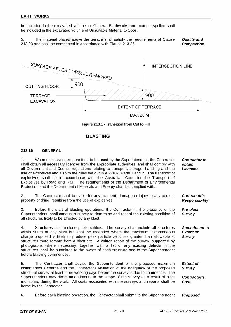
2. Following excavation to the cutting floor, a terrace shall be excavated for thewidth of the selected material zone (or subbase layer, where no selected material zone)to a depth of 900mm below and parallel to the cutting floor, as shown in Figure 213.1,unless otherwise approved by the Superintendent.
TerraceConstruction
3. The terrace shall extend into the cut to the point where the cutting floor is 900mmbelow the original stripped surface, or a distance of 20 metres, whichever is the lesser.
Extent ofTerrace
4. The material excavated shall be either incorporated in the embankments orspoiled as directed by the Superintendent. Material incorporated in embankments shall
ExcavatedQuantity
EARTHWORKS
213 - 8 AUS-SPEC-2\WA-213 March 2001CITY OF SWAN
be included in the excavated volume for General Earthworks and material spoiled shallbe included in the excavated volume of Unsuitable Material to Spoil.
5. The material placed above the terrace shall satisfy the requirements of Clause213.23 and shall be compacted in accordance with Clause 213.36.
Quality andCompaction
Figure 213.1 - Transition from Cut to Fill
BLASTING
213.16 GENERAL
1. When explosives are permitted to be used by the Superintendent, the Contractorshall obtain all necessary licences from the appropriate authorities, and shall comply withall Government and Council regulations relating to transport, storage, handling and theuse of explosives and also to the rules set out in AS2187, Parts 1 and 2. The transport ofexplosives shall be in accordance with the Australian Code for the Transport ofExplosives by Road and Rail. The requirements of the Department of EnvironmentalProtection and the Department of Minerals and Energy shall be complied with.
Contractor toobtainLicences
2. The Contractor shall be liable for any accident, damage or injury to any person,property or thing, resulting from the use of explosives.
Contractor'sResponsibility
3. Before the start of blasting operations, the Contractor, in the presence of theSuperintendent, shall conduct a survey to determine and record the existing condition ofall structures likely to be affected by any blast.
Pre-blastSurvey
4. Structures shall include public utilities. The survey shall include all structureswithin 500m of any blast but shall be extended where the maximum instantaneouscharge proposed is likely to produce peak particle velocities greater than allowable atstructures more remote from a blast site. A written report of the survey, supported byphotographs where necessary, together with a list of any existing defects in thestructures, shall be submitted to the owner of each structure and to the Superintendentbefore blasting commences.
Amendment toExtent ofSurvey
5. The Contractor shall advise the Superintendent of the proposed maximuminstantaneous charge and the Contractor's validation of the adequacy of the proposedstructural survey at least three working days before the survey is due to commence. TheSuperintendent may direct amendments to the scope of the survey as a result of blastmonitoring during the work. All costs associated with the surveys and reports shall beborne by the Contractor.
Extent ofSurvey
Contractor'sCost
6. Before each blasting operation, the Contractor shall submit to the Superintendent Proposed

EARTHWORKS
AUS-SPEC-2\WA-213 March 2001 213 - 9 CITY OF SWAN
written details of the proposed blasting procedure including the quantity and type ofexplosive to be detonated, the blasting pattern to be used and measures proposed tolimit noise and to ensure that vibration from blasting does not adversely affect nearbystructures. This action constitutes a HOLD POINT. The Superintendent’s sighting of thenecessary licences and approval to the submitted details of blasting operations isrequired prior to the release of the hold point. Release of the hold point does not in anyway reduce the Contractor’s responsibility set out in paragraph 2 of this Clause.
BlastingProcedure
HP
7. Ground vibration caused by blasting shall not exceed the values of peak particlevelocity listed in Table 213.2:
GroundVibration
Point of Potential Damage(within 1km of blasting site)
Peak Particle Velocity
Completed and cured bridge structures orsub-structures(eg completed abutment)
25 mm/sec
Bridgeworks and structural retaining wallsunder construction
20 mm/sec
Residential premises, schools, hospitalsand other buildings
5 mm/sec(with 10% not to exceed 10 mm/sec)
Buildings or monuments of historicalsignificance
2 mm/sec
Table 213.2 - Limiting Peak Particle Velocity
8. The Contractor shall advise all residents within a radius of 1km, by letter dropbefore blasting operations commence, of the likely times, frequency and duration ofblasting and precautions being taken to ensure that damage to property will not result.
Advice toResidents
9. Unless otherwise approved, blasting operations shall be confined to the periodsMondays to Fridays (excluding public holidays), 9am to 3pm.
Time Limits
10. When blasting operations are being carried out, precautions shall be takenrelating to the safety of persons and animals and the road shall be closed to traffic andthe appropriate signs erected in accordance with the Specification for CONTROL OFTRAFFIC. A standard warning procedure such as that given in the AUSTROADSExplosives in Roadworks, Users Guide 1982, shall be established and observed at alltimes.
SafetyPrecautions
213.17 PRESPLITTING
1. Where presplitting is carried out the spacing of presplit drill holes shall notexceed 750mm centre to centre.
Presplitting
213.18 BLASTING RECORDS
1. The Contractor shall maintain accurate records of each blast showing the detailslisted below:-
Records to bekept
Date and time of blast
EARTHWORKS
213 - 10 AUS-SPEC-2\WA-213 March 2001CITY OF SWAN
Location, number and diameter of holes loaded
Depth of each hole loaded
Inclination of holes
Maximum and minimum burden
Types of explosives used
Charge distribution in each hole
Maximum instantaneous charge
Delay periods and sequence
Total amount of charges in the blast
Length and type of stemming in each hole
2. The records shall be prepared as holes are loaded and signed by thePowderman. A copy shall be provided to the Superintendent on the day of the blast.
RecordPreparation
213.19 CONTROL OF AIR BLAST OVER-PRESSURE
1. This Clause shall apply only where a noise sensitive location exists within 1km ofthe blasting site.
Incidence
2. The Contractor shall ensure all works are undertaken in accordance with theEnvironmental Protection Act 1986 and the Environmental Protection (Noise) Regulations1997.
Noise ControlRegulations
3. The noise emanating from blasting operations shall not exceed an over-pressurelevel of 115 decibels (linear peak) at any noise sensitive location (such as residentialpremises, schools or hospitals). Up to 10 per cent of the total number of blasts mayexceed this value provided a level of 120 decibels is not exceeded at any time.
NoiseLimitations
4. The Contractor shall arrange for the monitoring of air blast over-pressure toensure compliance with the specified limits. All monitoring shall be carried out bypersonnel possessing current NATA registration for such monitoring. All test results shallbe reported on NATA endorsed test certificates which shall include a clear statement asto compliance or non-compliance with the requirements of this Specification. In general,a monitoring location will be near the perimeter of the noise sensitive location at the pointclosest to the maximum charge. The Contractor shall submit a copy of the monitoringrecord to the Superintendent.
Monitoring ofAir Blast Over-pressure
5. In the event that the measured air blast over-pressure exceeds the specifiedlimits, the Contractor shall suspend further blasting work and shall submit to theSuperintendent proposals detailing any additional steps and precautions the Contractorshall take to ensure that for any future blast, the limiting over-pressure shall not beexceeded. The Contractor shall not resume any blasting until such proposals have beensubmitted.
Excessive AirBlast Over-Pressure
213.20 CONTROL OF GROUND VIBRATION
1. The Contractor shall arrange for the monitoring of ground vibrations to ensurecompliance with the peak particle velocity limits shown in Table 213.2. All monitoringshall be carried out by personnel possessing current NATA registration for suchmonitoring. All test results shall be reported on NATA endorsed test certificates which
MonitoringVibrations

EARTHWORKS
AUS-SPEC-2\WA-213 March 2001 213 - 11 CITY OF SWAN
shall include a clear statement as to compliance or non-compliance with therequirements of this Part of the Specification. In general a monitoring location shall benear the perimeter of the structure or building at the point closest to the maximumcharge. The Contractor shall submit a copy of the monitoring record to theSuperintendent.
2. To minimise the risk of peak particle velocity limits being exceeded, theContractor shall develop a blasting site relationship between peak particle velocity,distance and blasting charge.
Blasting SiteRelationship
3. For the first blast, monitors shall be set up at not less than five points at varyingdistances away from the blasting site. The Maximum Instantaneous Charge for the firstblast shall not exceed that calculated from the following formula:
MIC 0.5
D
PPV1140
0 625
2
.
where MIC = Maximum Instantaneous Charge in kilograms
D = Distance in metres from charge to the point of potential damage
PPV = limiting peak particle velocity from Table 213.2
MaximumInstantaneousCharge
4. A log-log (base 10) graph of measured peak particle velocity (vertical axis)versus Scaled Distance (horizontal axis) shall be plotted, where
Scaled Distance = DMIC
The mean regression line shall be obtained by the least squares method.
5. For subsequent blasts, the MIC and other aspects of blast design may beadjusted provided that further ground vibration monitoring is undertaken and the meanregression line redetermined to demonstrate that peak particle velocity limits are notexceeded. The Contractor shall make the regression line plots available to theSuperintendent, if so requested.
Adjustment ofBlast Design
UNSUITABLE MATERIAL
213.21 GENERAL
1. Unsuitable material is that occurring below the designed floor level of cuttingsand below the nominated depth for stripping topsoil beneath embankments, which theSuperintendent deems to be unsuitable for embankment or pavement support in itspresent position.
Definition
2. Such material shall be excavated to the extent directed by the Superintendent. Material removed as unsuitable, as directed by the Superintendent, shall be spoiled inaccordance with Clause 213.34.
Extent ofExcavation
3. After removal of the unsuitable material, the floor of the excavation shall be re-presented to the Superintendent for inspection, prior to backfilling with replacementmaterial, to determine whether a sufficient depth of unsuitable material has beenremoved. This action constitutes a HOLD POINT. The Superintendent’s approval to the
FloorInspection

EARTHWORKS
213 - 12 AUS-SPEC-2\WA-213 March 2001CITY OF SWAN
floor of the excavation is required prior to the release of the hold point.HP
4. Prior to placing replacement material the excavated surface shall be compactedin accordance with Clause 213.36.
5. The unsuitable material which has been removed shall be replaced with materialfrom cuttings, or with material borrowed in accordance with Clause 213.35, of the qualityspecified in Clause 213.23. Replacement material is deemed to form part ofembankment construction. It shall be placed in accordance with Clause 213.26 andcompacted in accordance with Clause 213.36.
ReplacementMaterial
6. All costs associated with reworking or replacing any material which theSuperintendent deems to have become unsuitable because of inappropriate constructionactivities shall be borne by the Contractor.
Contractor'sCosts
EMBANKMENT CONSTRUCTION
213.22 SCOPE
1. Embankment construction includes all operations associated with the preparationof the foundation areas on which fill material is to be placed, the placing and compactingof approved material within areas from which unsuitable material has been removed inaccordance with Clause 213.21, the placing and compacting of fill material and ofmaterials of specified quality in nominated zones throughout the Works and all otheractivities required to produce embankments as specified to the alignment, grading anddimensions shown on the Drawings. It also includes any pretreatment such as breakingdown or blending material or drying out material containing excess moisture.
Extent of Work
213.23 EMBANKMENT MATERIAL
1. Material for embankment construction shall be obtained from the cuttings withinthe Works in accordance with Clause 213.11, supplemented by borrow in accordancewith Clause 213.35 and from other sources as approved by the Superintendent ifnecessary. The material shall be free of tree stumps and roots, clay, topsoil, steel,organic material and other contaminants and shall be capable of being compacted inaccordance with Clause 213.36.
Location andQuality
2. The work shall be programmed so that material of the quality specified in Clause213.26 and 213.30 for the upper zones of the formation is available when required.
Selection ofMaterial
213.24 FOUNDATIONS FOR EMBANKMENTS
1. Following removal of topsoil in accordance with Clause 213.07, the embankmentfoundation area shall be made available for inspection by the Superintendent. Thisaction constitutes a HOLD POINT. The Superintendent’s approval to the embankmentfoundation is required prior to the release of the hold point.
Inspection
HP
2. Where the Superintendent considers that any underlying material is unsuitable,the Superintendent may direct that it be removed and replaced in accordance withClause 213.21.
UnsuitableMaterial
(a) Foundations for Shallow Embankments
1. Shallow embankments are those embankments of a depth less than 1.5 metresfrom the top of pavement to natural surface. After removal of topsoil the Contractor shallsurvey and work out the extent of the area of shallow embankments.
ShallowEmbankments
EARTHWORKS
AUS-SPEC-2\WA-213 March 2001 213 - 13 CITY OF SWAN
2. Material in the foundations for shallow embankments which does not meet therequirements specified in Annexure 213A, shall be deemed unsuitable in accordancewith Clause 213.21 and shall be replaced by material of the specified quality.
UnsuitableMaterial
3. Foundations for shallow embankments shall be prepared for embankmentconstruction after removing topsoil and unsuitable material, by loosening the materialexposed to a depth of 200mm, adjusting the moisture content of the loosened materialand compacting as specified in Clause 213.36. The Contractor shall use equipment andtechniques to minimise surface heaving or other foundation damage.
Preparation ofFoundations
(b) Other Embankments
1. For all other embankments the foundation shall be prepared by grading andlevelling the general area, adjusting the moisture content where necessary andcompacting the top 200mm as specified in Clause 213.36.
Preparation
2. Where a bridging layer has been specified as a foundation treatment in theContract documents, it shall be supplied and placed as part of General Earthworks. Thebridging layer shall consist of free-draining granular material with or without geotextileinterlayer as specified on the Drawings. The granular material shall be end-dumped andspread in a single layer and in sufficient depth to allow the passage of earthmovingequipment with minimal surface heaving. The compaction requirements of Clause213.36 shall not apply to the bridging layer. Where it is necessary to import suitablematerial from off site and no suitable borrow source is available as provided in Clause213.35, the supply and placing of the bridging layer shall be treated as a Variation to theContract.
Bridging Layer
3. A bridging layer may also be employed, subject to the approval of theSuperintendent, where ground water or seepage is encountered in the foundation area orwhere the Contractor demonstrates that it is impracticable to achieve the degree ofcompaction specified for the foundation in Clause 213.36. A bridging layer shall not beacceptable if its proximity to the pavement is likely to affect the pavement design.
Seepage fromFoundations
4. As an alternative to a bridging layer, the Superintendent may approve of aworking platform created by the chemical stabilisation of in situ material in accordancewith the Specification for STABILISATION.
WorkingPlatform
213.25 HILLSIDE EMBANKMENTS
1. Where embankments are to be constructed on or against any natural slopes orthe batters of existing embankments, the existing slope or batter, if it is steeper than 4horizontal to 1 vertical in any direction shall be cut in the form of horizontal terraces overthe whole area to be covered by new filling. The existing slope or batter shall be steppedin successive terraces, each at least 1 metre in width, the terraces to be cutprogressively as the embankment is placed. Wherever possible terraces shall coincidewith natural discontinuities. Subsoil drainage may be required in some instances. Material thus excavated shall be compacted as part of the new embankment material.
HorizontalTerraces
2. No account shall be taken of the material removed in terracing when determiningthe General Earthworks excavated volume.
ExcavatedVolume
213.26 PLACING FILL FOR EMBANKMENT CONSTRUCTION
1. The methods of excavation, transport, depositing and spreading of the fillmaterial shall be selected so as to ensure that the placed material is uniformly mixed.
Uniformity ofMaterial

EARTHWORKS
213 - 14 AUS-SPEC-2\WA-213 March 2001CITY OF SWAN
2. The embankment shall be constructed so as to derive its stability from theadequate compaction of the fine material embedding the large rock pieces rather thanmechanical interlock of the rock pieces. The fine material shall be compacted to meetthe requirements of Clause 213.36.
EmbankmentStability
3. Fill material for embankment construction shall be placed in layers parallel to thegrade line and compacted in accordance with Clause 213.36. The layers shall be ofuniform compacted thickness not exceeding 200mm, except that where more than 25 percent by volume of the filling consists of rock with any dimension larger than 150mm, theSuperintendent may approve an increase in the compacted layer thickness to 300mm,provided that the relative compaction specified in Clause 213.36 is attained.
LayerThickness
4. The maximum dimension, measured in any direction, of rock pieces in the fillmaterial for embankment construction shall not exceed two-thirds of the approvedcompacted layer thickness. Any larger rock pieces shall be reduced in size forincorporation in the embankment layers.
Maximum SizeRock Pieces
5. Rock material shall be broken down and evenly distributed through the fillmaterial, and sufficient fine material shall be placed around the larger material as it isdeposited to fill the voids and produce a dense, compact embankment. Where theSuperintendent considers insufficient fine material is present to fill the voids, additionalfine material shall be obtained from other places in the work or by a change in themethod of winning fill material.
Grading of FillMaterial
6. Stony patches with insufficient fine material to fill the voids shall be reworked withadditional fine material being blended in to achieve a dense, compact layer. The cost ofany reworking shall be borne by the Contractor.
ReworkingStony PatchesContractor'sCost
7. In placing embankment layers, the Contractor shall use equipment andtechniques to avoid surface heaving or other damage to the foundations and underlyingembankment layers.
EquipmentSelection forPlacement
8. After compaction, embankment material in the zone(s) below the selectedmaterial zone (or subbase layer, where no selected material zone) shall have a CBRvalue not less than that quoted in Annexure 213A for the depth(s) specified in Annexure213A.
CBR Value
9. For the purpose of this Clause, the CBR value of the material shall bedetermined by Test Method AS 1289.6.1.1
Test Method
10. The Contractor shall be responsible for determining suitable sources of materialand for any processing to satisfy these quality requirements.
Contractor'sResponsibility
213.27 EMBANKMENT BATTERS
1. The batter slopes shown on the Drawings represent the estimated requirementsfor the expected types of materials, and may be subject to redetermination by theSuperintendent according to the Superintendent's assessment of the materialsencountered.
Batter Slopes
2. When completed, the average planes of the batters of embankments shallconform to those shown on the Drawings or as determined by the Superintendent.
SlopeTolerances
(a) For a vertical distance to 1m below the shoulder, no point on thecompleted batter shall vary from the specified slope line by more than 150mm whenmeasured at right angles to the slope line.
(b) At distances greater than 1m vertically below the shoulder, no point onthe completed batter shall vary from the specified slope line by more

EARTHWORKS
AUS-SPEC-2\WA-213 March 2001 213 - 15 CITY OF SWAN
than 300mm when measured at right angles to the slope.
However, in no case shall the edge of the formation at the underside of the pavement benearer to the roadway than shown on the Drawings.
3. Undulations in the general plane of the batter shall not be permitted. SlopeUndulations
4. Where the Superintendent redetermines the slope of any section of anembankment batter which has been completed in accordance with this Clause theSuperintendent shall order a Variation to the contract for the resetting out and removal oraddition of fill material and retrimming of the batter.
Slope Redeter-mination
213.28 ROCK FACING OF EMBANKMENTS
1. Where shown on the Drawings, embankment batters (including embankments atbridge abutments) shall be provided with a facing of clean, hard, durable rock.
Extent
2. The rock facing shall be built up in layers ahead of each layer of filling. Rockmay be placed by hand or plant but shall be placed in such a manner that its leastdimension is vertical and that mechanical interlock between the larger stones occurs. Any rock deposited in the rock facing which has an excess of fine material surrounding itshall be removed together with the excess fine material and replaced.
MechanicalInterlock
3. The Contractor shall adjust its working methods and programme the work so asto obtain hard and durable rock of the specified dimensions as it is required. The spacebetween larger batter rocks shall be filled with progressively smaller rocks to form a'graded filter' which prevents the leaching out of fines from the fill material but which doesnot overfill the voids between larger rocks, or cause the larger rocks to lose contact withone another. Fine material shall not cover the outside of the rocks on the face of thebatter.
Graded Filter
4. Where shown on the Drawings, or approved by the Superintendent, anappropriate geotextile may be used to prevent the leaching out of fines from the fillmaterial.
Geotextile
5. The Contractor shall exercise extreme caution whilst placing the rock facing. Where embankment material is placed above other roads in use the outer rock layershall be placed in such a manner as to prevent spillage down the batter and onto theroadway. The Contractor shall ensure that, under no circumstances, could any rock bedislodged and roll onto any adjacent roadway or track in use.
Caution inPlacement
213.29 TRIMMING TOPS OF EMBANKMENTS
1. The tops of embankments shall be trimmed parallel to the designed grade line atlevels equal to the finished surface level less the thicknesses of pavement courses andthe selected material zone if applicable.
Levels
2. The tops of embankments at these levels shall be compacted to meet therequirements of Clause 213.36 and trimmed so that they do not vary more than 10mmabove or 40mm below the levels as calculated above.
Tolerances
3. Prior to placing any subsequent pavement layers over the completed top ofembankment filling, the Contractor shall present the completed surface to theSuperintendent for inspection. The Contractor shall verify as part of the quality systemthat the completed surface has achieved full conformance with all respects of thisSpecification. This action constitutes a HOLD POINT. The Superintendent's approval ofthe completed top of the embankment is required prior to the release of the hold point.
HP

EARTHWORKS
213 - 16 AUS-SPEC-2\WA-213 March 2001CITY OF SWAN
213.30 SELECTED MATERIAL ZONE
1. A selected material zone may be indicated on the Drawings as a zone below thesubbase layer and the following quality requirements:
Dimension andQuality
(a) It shall be free from stone larger than 100mm maximum dimension
(b) The fraction passing 19.0mm AS sieve shall have a CBR value of notless than that quoted in Annexure 213A.
2. When chemical stabilisation is specified these requirements shall apply to theselected material immediately prior to incorporating the stabilising agent.
3. The selected material shall be obtained from cuttings excavated under theContract or from borrow areas as specified in Clause 213.35. If necessary, theContractor shall use working methods to yield material for the selected material zone bybreaking down oversize rock or by other means, including processing through a crusher,to ensure that the resulting material conforms to the requirements of this Clause.
WinningMaterial
4. The Contractor shall ensure that any material encountered of the qualityspecified for the selected material zone shall be either placed directly in the selectedmaterial zone or stockpiled at locations approved by the Superintendent for future use bythe Contractor in the selected material zone until at least sufficient material is reserved tocomplete the selected material zone over the whole work. Should the Contractor fail toconserve material of the specified quality, the Superintendent may direct that material ofequivalent quality be provided. The cost of providing such extra material shall be borneby the Contractor.
Selection ofMaterialContractor'sCost
5. The Contractor shall have no right to monetary compensation or a claim fordamages in respect of any loss the Contractor may claim to have suffered by reason ofthe Contractor's failure to reserve sufficient selected material or by reason of stockpilingmaterial for the selected material zone.
Cost ofHandling
6. The selected material zone shall be placed and compacted in layers with thecompacted thickness of each layer not exceeding 150mm. Compaction shall be asspecified in Clause 213.36.
LayerThickness
7. After placement the selected material shall be homogeneous and free frompatches containing segregated stone or excess fines. There shall be no areas containingmaterial which does not comply with the specified requirements of this Clause.
HomogeneousLayers
8. The top of the selected material zone shall be compacted and trimmed parallelwith the designed grade line at a level equal to the finished surface level minus thethickness of pavement layers adopted. The tolerances for the trimmed levels are given inAnnexure 213A.
Compact andTrim
9. Prior to placing any subsequent pavement layers over the completed selectmaterial zone surface, the Contractor shall present the completed surface to theSuperintendent for inspection. The Contractor shall verify as part of the quality systemthat the completed surface has achieved full conformance with all respects of thisSpecification. This action constitutes a HOLD POINT. The Superintendent’s approval tothe compacted and trimmed top of selected material zone is required prior to the releaseof the hold point.
HP

EARTHWORKS
AUS-SPEC-2\WA-213 March 2001 213 - 17 CITY OF SWAN
213.31 FILL ADJACENT TO STRUCTURES
1. Supply and placement of fill adjacent to structures shall be deemed to be part ofGeneral Earthworks.
Payment
2. For the purpose of this Clause, structures shall include bridges, precast andcast-in-place box culverts and retaining walls. Fill adjacent to other culverts anddrainage structures shall be provided in accordance with the Specifications for PIPEDRAINAGE and DRAINAGE STRUCTURES as appropriate.
StructureTypes
3. No filling shall be placed against structures, retaining walls, headwalls orwingwalls within 21 days after placing of the concrete, unless the walls are effectivelysupported by struts to the satisfaction of the Superintendent, or when the Contractor candemonstrate that 85 per cent of the design strength of the concrete has been achieved.
Time ofPlacement
213.32 TREATMENT AT WEEPHOLES
1. Drainage adjacent to weepholes shall be provided by either a layer of brokenstone or river gravel consisting of clean, hard, durable particles graded from 50mm to10mm such that:
Grading
(a) The maximum particle dimension shall not exceed 50mm
(b) No more than 5 per cent by mass shall pass the 9.5mm A.S. sieve.
2. The broken stone or river gravel shall be continuous in the line of the weepholes,extend at least 300mm horizontally into the fill and extend at least 450mm verticallyabove the level of the weepholes.
Extent
3. Alternatively the Contractor may provide a synthetic membrane of equivalentdrainage characteristics at no extra cost to the Principal. It shall be stored and installed inaccordance with Manufacturer's instructions. The use of a synthetic membrane shall besubject to the Superintendent's approval.
SyntheticMembrane
213.33 SELECTED BACKFILL
1. Selected backfill shall be placed adjacent to structures in accordance with Table213.3. The selected backfill shall consist of a granular material having a maximumdimension not exceeding 50mm and a Plasticity Index, determined by AS 1289.3.3.1,neither less than 2 nor more than 12.
Quality

EARTHWORKS
213 - 18 AUS-SPEC-2\WA-213 March 2001CITY OF SWAN
Structure Type Selected Backfill
Width Height
Bridge Abutments 2m H
Cast-in-place Box Culverts H/3 H + 300mm
Corrugated Steel Pipes and Arches 0.5m H + 500mm
Retaining Walls H/3 H
(Where H = height of structure)
Table 213.3 - Selected Backfill, Width and Height
2. The selected backfill shall be placed in layers, with a maximum compactedthickness of 150mm. Layers shall be placed simultaneously on both sides of box culvertsand other drainage structures to avoid differential loading. Compaction shall start at thewall and proceed away from it, and shall meet the requirements of Clause 213.36.
Placement inLayers
3. The existing embankment slope behind the structure shall be cut in the form ofsuccessive horizontal terraces, each terrace being at least 1m in width, and the selectedbackfill shall be placed in accordance with Clause 213.26.
HorizontalTerraces
4. No selected backfilling shall be placed against structures, retaining walls,headwalls or wingwalls within 21 days after placing of the concrete, unless the walls areeffectively supported by struts to the satisfaction of the Superintendent, or when theContractor can demonstrate that 85 per cent of the design strength of the concrete hasbeen achieved.
Time ofPlacement
5. Where a bridge deck is being concreted adjacent to an abutment, no filling shallbe placed against the abutment within twenty-one days after placing concrete in thebridge deck, unless approved by the Superintendent.
Adjacent toConcrete Deck
6. In the case of spill-through abutments, rocks shall not be dumped against thecolumns or retaining walls but shall be built up evenly by individual placement around oragainst such structures.
Spill throughAbutments
7. In the case of framed structures, embankments at both ends of the structureshall be brought up simultaneously, the difference between the levels of theembankments at the respective abutments, shall not exceed 500mm.
FramedStructures
213.34 SPOIL
1. Spoil is surplus material from excavations under the Contract which is notrequired to complete the Works as specified or material from excavations under theContract whose quality the Superintendent deems to be unacceptable for incorporation inthe Works. The Contractor shall bear all costs associated with the acquisition of planningapproval by Council’s Town Planning Manager should this be determined as necessaryby the Superintendent.
Definition
Contractor’sCost
2. Where there is surplus material the Superintendent may direct that flatter batterslopes be provided on embankments which have not been commenced, and/or directthat the excess material be used in the uniform widening of embankments, the surface ofwhich shall be shaped so as to provide a tidy appearance and effective drainage. Thesurplus material shall be spread and compacted as specified in Clauses 213.26 and213.36 for material in embankments.
Use inEmbankments

EARTHWORKS
AUS-SPEC-2\WA-213 March 2001 213 - 19 CITY OF SWAN
3. Alternatively, spoil shall be disposed of in the manner and at locations approvedby the Superintendent. Surplus material so deposited shall be compacted as specified inClause 213.36 for material in embankments or to such lesser extent as may be approvedby the Superintendent. Disposal of spoil up to five kilometres from the point ofexcavation shall be deemed to be included in General Earthworks. Where haulageexceeds five kilometres, payment shall be made at the rate nominated in Annexure 213Afor haulage of spoil.
Disposal ofSpoil
213.35 BORROW
1. Unless provided by the Contract, borrow will only be authorised by theSuperintendent if, in constructing cuttings and embankments to the batter slopesspecified or directed by the Superintendent or in providing materials of the qualityspecified, and not by reason of excess widening of embankments or wastage by theContractor of material of the quality specified in Clauses 213.23, 213.28, 213.29 or213.31, there is an overall deficiency in either the quantity or the quality of materialrequired to complete the Works.
Borrow to beAuthorized
2. Where borrow material is required to complete the Works as specified, thelocation of borrow sites shall be as approved by the Superintendent, and the quality ofmaterial shall be acceptable to the Superintendent in accordance with Clauses 213.23,213.28 or 213.31 as appropriate. The Contractor shall bear all costs associated with theacquisition of Planning approval by Council’s Town Planning Manager should this bedetermined as necessary by the Superintendent. The edges of borrow sites shall be nocloser than 3m from any fence line, road reserve boundary or edge of excavation orembankment. Adequate clearance shall be provided for the construction of catch drains. Borrow sites shall have drainage outlets acceptable to the Superintendent, cut batterslopes not steeper than 4h to 1v, and shall be left by the Contractor in a tidy and safecondition.
Borrow SiteCharacteristics
Contractor’sCost
3. For borrow within the defined working area for the Works as specified, sitepreparation shall be in accordance with the Specification for CLEARING ANDGRUBBING and Clause 213.07. Restoration of borrow sites shall be carried out inaccordance with the Specification for LANDSCAPING.
Site Prepa-ration andRestoration
4. If borrow material is obtained by uniformly widening a cutting, the requirementsof Clauses 213.11, 213.12 and 213.14 as to the redetermination of batter slopes, thetrimming of batters and the compaction of floors of cuttings respectively shall apply to theborrow area.
Widening ofCutting
5. Borrow from within the specified working area shall be deemed to be part ofGeneral Earthworks except that additional payment for haulage will be made at the ratenominated in Annexure 213A for haulage of borrow where the authorised borrow sitesare more than five kilometres from the point of delivery.
Payment
6. If the Superintendent accepts that borrow must to be obtained from locationsoutside the specified working area for the Works, such work shall be treated as aVariation to the Contract. The Contractor shall be responsible for obtaining any permitsrequired for entry on land and for the payment of any royalty for such borrow material. The Contractor shall also comply with any requirements of the Environmental ProtectionAct, Town Planning and Development Act, the Local Council, land owners, theDepartment of Conservation and Land Management, as appropriate.
ContractorResponsibility

EARTHWORKS
213 - 20 AUS-SPEC-2\WA-213 March 2001CITY OF SWAN
COMPACTION AND QUALITY CONTROL
213.36 COMPACTION AND MOISTURE REQUIREMENTS
1. In areas listed below, all layers shall be uniformly compacted to not less than therelative compaction specified before the next layer is commenced. Each layer of materialshall be trimmed prior to and during compaction to avoid bridging over low areas. Asmooth surface shall be presented at the top of each layer.
Trimming andCompaction
2. The following areas shall be compacted to provide a relative compaction,determined by AS 1289.5.7.1 or AS 1289.5.4.1 for modified compactive effort, of not lessthan 92 per cent.
92%CompactionRequirements
- Each layer of material replacing unsuitable material as detailed in Clause213.21.
- Each layer of material placed in embankments, up to 1.5 metres from thetop of the pavement.
- Fill placed adjacent to structures up to 1.5 metres from the top ofpavement.
- Material in unsealed verges and within medians up to the level at whichtopsoil is placed.
- Spoil (excluding unsuitable material)
- All other areas except those where higher relative compaction isspecified.
3. Unsuitable material shall be stockpiled as directed by the Superintendent andcompacted by track rolling.
UnsuitableMaterial
4. The following areas shall be compacted to provide a relative compaction of notless than 97 per cent as determined by AS 1289.5.7.1 or AS 1289.5.4.1 for modifiedcompactive effort:
97%CompactionRequirements
- Foundations for shallow embankments.
- The whole area on the floor of cuttings.
- Each layer of the embankment within 1.5 metres from the top ofpavement.
- Each layer of the selected material zone as specified in Clause 213.30.
- Any areas of material of specified quality which may be shown on theDrawings or specified elsewhere behind kerbs and/or gutters or adjacentto rigid pavements.
- The fill material placed adjacent to structures as specified in Clauses213.31 and 213.33 in each layer within 1.5 metres from the top of thepavement.

EARTHWORKS
AUS-SPEC-2\WA-213 March 2001 213 - 21 CITY OF SWAN
5. Where the vertical alignment design is such that a substantial portion of the roadis required to be built at or close to natural surface, the prepared subgrade shall beconsidered to be in shallow cutting. Shallow cutting is defined as cutting to a depthbelow natural surface of less than 0.5 metres. The floor of shallow cutting shall betreated as specified in Clauses 213.14 and 213.15 and shall be compacted to provide arelative compaction determined by AS 1289.5.7.1 or AS 1289.5.4.1, for modifiedcompactive effort, of not less than 97 per cent for a depth of 200mm.
ShallowCuttingDefinition
6. When shallow cutting conditions occur and with written approval of theSuperintendent the requirements specified for transition from cut to fill (Clause 213.15)may be modified such that the depth of terrace excavation at the transition from cut to fillis reduced from 900mm to 250mm.
Cut-FillTransition
7. Sections of the works where the ripping or loosening of the cutting floor is notrequired and/or where provision of “proof-rolling” to the Superintendent’s satisfaction isrequired are indicated in Annexure 213A. Proof rolling shall be in accordance withClause 213.38.
Proof Rolling
8. At the time of compaction the moisture content of the material shall be adjustedso as to permit the specified compaction to be attained at a moisture content which,unless otherwise approved by the Superintendent, is within the range set out in Annexure213A of the optimum moisture content as determined by AS 1289.5.1.1 or AS 1289.5.7.1. Material which becomes wetted up after placement shall not be compacted until it hasdried out so that the moisture content is within this range. The drying process may beassisted by aeration, or where approved by the Superintendent, by the use of hydrated orquick lime at the Contractor's cost. Alternatively the Contractor may transport the wetmaterial to a stockpile site for drying out and later use as fill material. The cost oftransport to stockpile for drying out and later use shall be borne by the Contractor. Ifthere is insufficient moisture in the material for it to be compacted as specified, watershall be added. The added water shall be applied uniformly and thoroughly mixed withthe material until a homogeneous mixture is obtained. The costs of such wetting ordrying the material to be compacted shall be borne by the Contractor.
MoistureContent
Contractor'sCost forDrying andWetting
9. Compaction shall be undertaken to obtain the specified relative compaction forthe full depth of each layer in embankments and for the full width of the formation overthe entire length of the work. Compaction shall be completed promptly to minimise thepossibility of rain damage.
PromptCompaction
10. Any material placed by the Contractor that has attained the specified relativecompaction but subsequently becomes wetted up so that the moisture content is greaterthan the apparent optimum, determined by AS 1289.5.7.1, shall be dried out anduniformly recompacted to the required relative compaction in accordance with thisClause before the next layer of material is placed. Alternatively, the Contractor mayremove the layer of wetted material to a stockpile site for drying and later re-use. Thecost of the removal to stockpile, drying out and reincorporation of the wet material shallbe borne by the Contractor.
MoistureContent aboveOptimumContractor'sCost
213.37 PROCEDURES FOR DETERMINING TEST LOCATIONS
1. Sampling locations for testing shall be determined as described in theSpecification Part for Quality Requirements.
Test Locations
2. The specified compaction and moisture tests shall be taken at the determinedlocations. Prior to testing the Contractor shall work the lot to ensure uniform moisturecontent and compaction of all material within the lot.
Contractor toPrepare Area
3. The test/s then taken shall be considered to represent the total volume ofmaterial placed within the lot.
Test Repre-sentation

EARTHWORKS
213 - 22 AUS-SPEC-2\WA-213 March 2001CITY OF SWAN
4. Where the Superintendent considers that the material which is present has notachieved uniformity required by this Clause or Clause 213.26, the Superintendent maytake or direct further testing. The Superintendent shall nominate the area represented bythe additional testing.
FurtherTesting
5. If such testing confirms that material not conforming to the Specification ispresent, the cost of such tests shall be borne by the Contractor. The Contractor shallcarry out remedial work as necessary to achieve conformance to the requirements ofClause 213.36.
Contractor'sCost
213.38 DEFLECTION MONITORING OR PROOF ROLLING
1. Following completion of the formation to the underside of the selected materialzone in accordance with Clause 213.24 and 213.26, and completion of the selectedmaterial zone in accordance with Clause 213.30, the Contractor shall make the workavailable in lots, for the Superintendent to carry out deflection monitoring or proof rollingThis action constitutes a HOLD POINT. The Superintendent’s approval to the completedformation following deflection monitoring or proof rolling is required prior to the release ofthe hold point.
FormationComplete
HP
2. A lot for deflection testing shall consist of a continuous length of formation of atleast 300m, or lesser length as approved by the Superintendent, and a singlecarriageway width which is generally homogeneous with respect to material andappearance. The Contractor shall identify the boundaries of each lot with stakes clearlylabelled to the satisfaction of the Superintendent. The cost of preparing the surface fordeflection monitoring or proof rolling is deemed to be included in the rate for GeneralEarthworks.
Lot Size
213.39 WIDENING OF FORMATION
1. Road shoulders and formation shall be widened to accommodate footpaths,guardfence (guardrail), streetlight plinths, emergency telephone bays and vehiclestanding areas as shown on the Drawings.
Provision forServices
213.40 MEDIAN AREAS
1. The batter slopes for median areas shall conform to those shown on theDrawings and undulations in the general plane of the batter slope shall not be permitted.
Batter Slope
2. For a horizontal distance of 2m from the edge of the shoulder, no point on thecompleted batter shall vary from the specified slope line by more than 50mm whenmeasured at right angles to the slope line within 24 hours after compaction. At distancesgreater than 2m horizontally from the edge of the shoulder, no point on the completedbatter shall vary from the specified slope line by more than 100mm when measured atright angles to the slope line within 24 hours after compaction.
BatterTolerances
3. The medians shall be graded so as not to pond water. Free Draining

EARTHWORKS
AUS-SPEC-2\WA-213 March 2001 213 - 23 CITY OF SWAN
SPECIAL REQUIREMENTS
213.41 RESERVED
213.42 RESERVED
213.43 RESERVED
213.44 RESERVED
EARTHWORKS
213 - 24 AUS-SPEC-2\WA-213 March 2001CITY OF SWAN
LIMITS AND TOLERANCES
213.45 SUMMARY OF LIMITS AND TOLERANCES
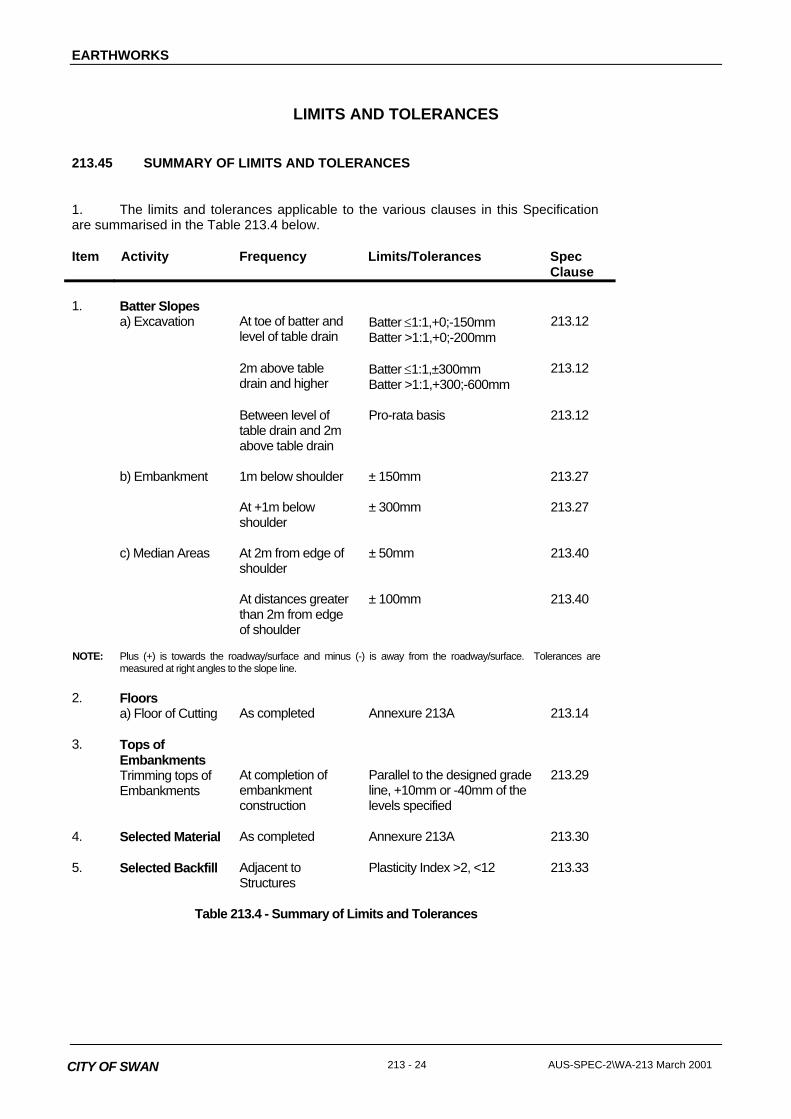
1. The limits and tolerances applicable to the various clauses in this Specificationare summarised in the Table 213.4 below.
Item Activity Frequency Limits/Tolerances SpecClause
1. Batter Slopesa) Excavation At toe of batter and
level of table drainBatter ≤1:1,+0;-150mmBatter >1:1,+0;-200mm
213.12
2m above tabledrain and higher
Batter ≤1:1,±300mmBatter >1:1,+300;-600mm
213.12
Between level oftable drain and 2mabove table drain
Pro-rata basis 213.12
b) Embankment 1m below shoulder ± 150mm 213.27
At +1m belowshoulder
± 300mm 213.27
c) Median Areas At 2m from edge ofshoulder
± 50mm 213.40
At distances greaterthan 2m from edgeof shoulder
± 100mm 213.40
NOTE: Plus (+) is towards the roadway/surface and minus (-) is away from the roadway/surface. Tolerances aremeasured at right angles to the slope line.
2. Floorsa) Floor of Cutting As completed Annexure 213A 213.14
3. Tops ofEmbankmentsTrimming tops ofEmbankments
At completion ofembankmentconstruction
Parallel to the designed gradeline, +10mm or -40mm of thelevels specified
213.29
4. Selected Material As completed Annexure 213A 213.30
5. Selected Backfill Adjacent toStructures
Plasticity Index >2, <12 213.33
Table 213.4 - Summary of Limits and Tolerances
EARTHWORKS
AUS-SPEC-2\WA-213 March 2001 213 - 25 CITY OF SWAN
MEASUREMENT AND PAYMENT
213.46 PAY ITEMS
1. Payment shall be made for all the activities associated with completing the work detailed in thisSpecification on a schedule of rates basis in accordance with Pay Items (a) to (f) inclusive.
2. A lump sum price for any of these items shall not be accepted.
3. If any item, for which a quantity of work is listed in the Schedule of Rates, has not been priced by theContractor it shall be understood that due allowance has been made in the prices of other items for the cost ofthe activity which has not been priced.
4. Control measures for erosion and sedimentation are measured and paid in accordance with theSpecification for CONTROL OF EROSION AND SEDIMENTATION.
5. Clearing and grubbing of stockpile sites and borrow areas is measured and paid in accordance withthe Specification for CLEARING AND GRUBBING.
6. Seeding and restoration of stockpile sites and borrow areas is measured and paid in accordance withthe Specification for LANDSCAPING.
7. Traffic control for blasting operations is measured and paid in accordance with the Specification forCONTROL OF TRAFFIC.
8. Fill adjacent to culverts, other than box culverts, and drainage structures is measured and paid inaccordance with the STORMWATER Specifications for PIPE DRAINAGE and DRAINAGE STRUCTURES asappropriate.
9. Selected backfilling to box culverts is measured and paid in accordance with the STORMWATERSpecification for PRECAST BOX CULVERTS.
10. Working platforms created by chemical stabilisation are measured and paid in accordance with theSpecification for STABILISATION.
Pay Item 213(a) REMOVAL AND STOCKPILING OF TOPSOIL
1. The unit of measurement shall be cubic metre as bank volume.
2. The volume shall be the sum of:-
(i) The volume removed from cuttings calculated by multiplying the area of cutting to be stripped ascalculated from the plans of natural surface or accepted Ground Model by the depth of topsoildirected to be removed by the Superintendent, plus;
(ii) The volume removed from under embankments calculated by multiplying the area to be stripped ascalculated from the plans of natural surface or accepted Ground Model by the depth of topsoilstripping as nominated in Annexure 213A, plus;
(iii) The additional volume of topsoil removed from shallow embankments below the depth nominated inAnnexure 213A and calculated on the basis of plan area multiplied by the directed depth ofexcavation, or as directed.
3. The schedule rate under this Pay Item includes all activities associated with stripping topsoil, cartingand placing into stockpile, then stabilising and trimming the stockpiles.

EARTHWORKS
213 - 26 AUS-SPEC-2\WA-213 March 2001CITY OF SWAN
Pay Item 213(b) GENERAL EARTHWORKS
1. The unit of measurement shall be the cubic metre measured as bank volume of excavation.
2. The schedule rate for this Pay Item shall be an average rate to cover all types of materialencountered during excavation and placed in embankments or spoil stockpiles, including both earth and rock.
3. Payment for General Earthworks shall include all activities associated with the excavation of materialand the construction of embankments, stockpiling of spoil, the haulage of material and any pretreatment suchas breaking down or blending material or drying out material containing excess moisture, except that:
- removal of unsuitable material to spoil shall be paid under Pay Item 213(c)
- extra costs in processing selected material shall be paid under Pay Item 213(d)
- overhaul of spoil or borrow shall be paid under Pay Items 213(e) and 213(f) respectively.
4. The base of the excavation shall be the designed floor level in accordance with Clause 213.14 and noaccount shall be taken of level tolerances.
5. The volume of earthworks in cuttings shall be determined by the surface to surface triangulationmethod, calculating the volume between the plans of natural surface or accepted Ground Model, the designedbatter lines and the base of the excavation; from which shall be deducted the volume of topsoil as calculatedunder Pay Item 213(a). No account shall be taken of the allowable batter tolerances or stepping of batters fortopsoiling.
6. Where unsuitable material from the foundations of shallow cuttings or material from cut to filltransitions is excavated and placed into embankments the volume shall be calculated from joint surveyscarried out immediately prior to, and after subsequent removal of the unsuitable material, or by other methodswhich may be approved by the Superintendent.
Pay Item 213(c) UNSUITABLE MATERIAL TO SPOIL
1. The unit of measurement shall be the cubic metre measured as bank volume of excavation.
2. This pay item refers only to unsuitable material as defined in Clause 213.21 which is removed to spoilstockpile.
3. If the material is such that the bank volume of excavation cannot be measured, the Superintendentshall determine the conversion factors to be applied to the loose volumes measured in haulage units or to themeasured stockpile volumes.
4. The schedule rate(s) under this Pay Item shall include all operations involved in the excavation,haulage, drying out, compaction or other activity required under Clause 213.21 for its disposal as spoil inaccordance with Clause 213.34.
5. When this Pay Item provides for ranges of provisional quantities, the rates shall be appliedsuccessively, but not cumulatively, as the volume of unsuitable material increases from one provisionalquantity range to the next higher range.
6. Each rate shall be applied as the sole payment due for all unsuitable material removed within eachquantity range, irrespective of the nature or quantity of the material removed.
Pay Item 213(d) SELECTED MATERIAL
1. The unit of measurement shall be the cubic metre measured as embankment volume in place in theselected material zone. The volume shall be determined by multiplying the theoretical plan area of the top ofthe selected material zone with its nominated thickness.
EARTHWORKS
AUS-SPEC-2\WA-213 March 2001 213 - 27 CITY OF SWAN
2. This pay item covers any extra costs involved in stockpiling, processing, placing, compaction andtrimming of material, including surface preparation for deflection monitoring in the selected material zone overand above those costs allowed for under Pay Item 213(b).
3. The width and depth shall be taken as shown on the Drawings or as directed by the Superintendent. No account shall be taken of level tolerances.
Pay Item 213(e) HAULAGE OF SPOIL
1. Where an approved location for spoil disposal is more than five kilometres by road from the point ofexcavation of material being spoiled, payment shall be made for haulage at the rate nominated inAnnexure 213A per bank cubic metre for each kilometre or part thereof in excess of five kilometres.
Pay Item 213(f) HAULAGE OF BORROW
1. Where an authorised borrow site that was not nominated in the Contract, is more than five kilometresby road from the point of delivery of borrow material to the Works, payment shall be made for haulage at therate nominated in Annexure 213A per bank cubic metre for each kilometre or part thereof in excess of fivekilometres.

EARTHWORKS
213 - 28 AUS-SPEC-2\WA-213 March 2001CITY OF SWAN
ANNEXURE 213A
EARTHWORKS - SUPPLEMENTARY INFORMATIONCLAUSE DESCRIPTION VALUE
213.07
The depth below natural surface up to which the removal and measurement oftop soil shall apply: _______mm
a) Cutting areas _______mm
b) Embankment areas _______mm
213.14
Minimum CBR value in cutting floors used for design of pavement 11%
213.14
Construction tolerances, of the designated grade and crossfall, for floors of + 10mm
cuttings after recompaction - 10mm
213.24
Requirements of material in foundations for shallow embankments:
Moisture Content - within the range of ______% to ______% of optimum to bedecided on site.
213.26 and213.30
Upper Zones of Formation
Selected Material Zone
Material within each zone shall have a CBR value of not less than the following,under the nominated test conditions:
Location MinimumCBR Value
Depth Nominated SoakingPeriod (Days)
a) Selected Material Zone
b) Material below Selected Material Zoneto 1.5 metre from top of pavement.
N/A
213.30
Construction tolerances of the designed grade and + 10mm
cross fall for Selected Material Zone + 10mm
213.34
Haulage of spoil under Pay Item 213(e) shall be payable at the rate of $___.___per bank cubic metre per kilometre in excess of 5 kilometres.
213.35
Haulage of borrow under Pay Item 213(f) shall be payable at the rate of $___.___per bank cubic metre per kilometre in excess of 5 kilometres.
213.36
Moisture Content of material placed in embankments: (test on site)
a) Material in upper zones of formation:- within the range of ____% to ____% of optimum
b) All other embankment material:- within the range of ____% to ____% of optimum
Shallow cuttings:
c) Sections of work nominated to be in shallow cutting:

EARTHWORKS
AUS-SPEC-2\WA-213 March 2001 213 - 29 CITY OF SWAN
d) Ripping or loosening [ is / is not ] required in shallow cutting.
e) Proof rolling of subgrade [ is / is not ] required.


